SWR engineering SR082002AT Microwave Flow Sensor User Manual BA SF english 0302
SWR engineering GmbH Microwave Flow Sensor BA SF english 0302
Contents
- 1. Revised manaul part 1
- 2. Manual part 2
Manual part 2
Electrical connection
Page 11
5. Electrical connection
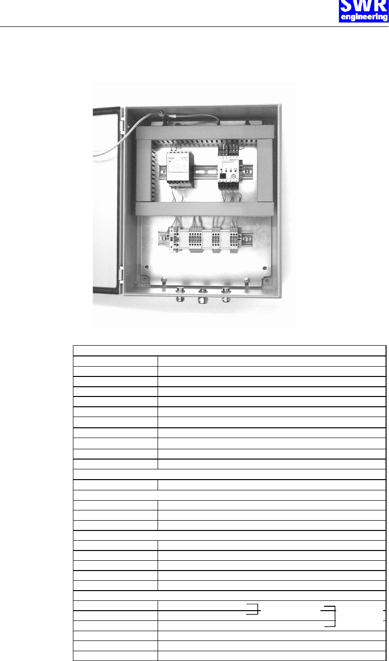
5.1 Connection of the separated version
Fig. 9: Electrical connection of the separated version
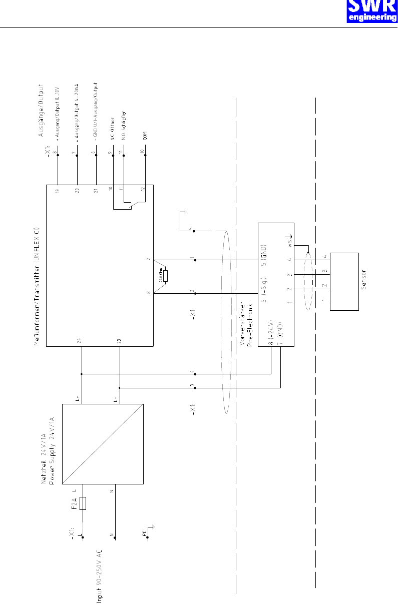
pre-amplifier
terminal no. connection
1 input sensor: flex no. 1
2 input sensor: flex no. 2
3 input sensor: flex no. 3
4 input sensor: flex no. 4
w input sensor: flex white
5 (–) GND
6 (+) signal
7 (–) GND
8 input (+)24 V DC
Evaluation unit
terminal no. connection
connection of supply voltage
L input supply voltage 230 V AC
N input supply voltage 230 V AC
protective earth ground
sensor connection
1 (sensor) (-) GND (from terminal 5 pre-amplifier)
2 (sensor) (+) signal (from terminal 6 pre-amplifier)
3 (sensor) (-) GND (from terminal 7 pre-amplifier)
4 (sensor) output (+)24 V DC (to terminal 8 pre-amplifier)
5 (sensor) ground (optional connection for shielded cable)
Outputs
6 (-) GND output
7 (+) output 4...20mA
8 (+) output 0...10 V
9 potential-free relay N.C.
10 potential-free relay COM
11 potential-free relay N.O.
current output voltage
output
Electrical connection
Page 12
5.2 Flow diagram of the separated version
Electrical connection
Page 13
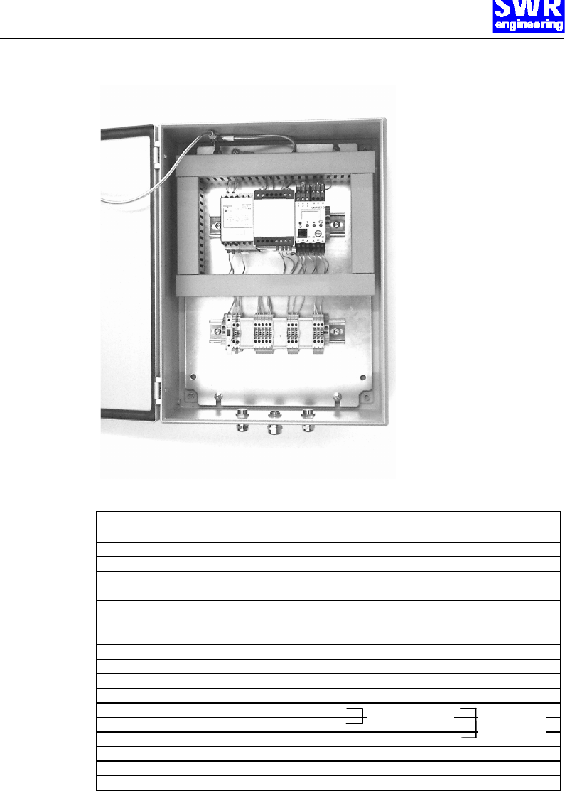
5.3 Connection compact version
Fig. 10: Electrical connection of compact version
evaluation unit
Terminal no. connection
connection of the supply voltage
L input supply voltage 230 V AC
N input supply voltage 230 V AC
protective earth ground
sensor connection
1 (sensor) input sensor: flex no. 1
2 (sensor) input sensor: flex no. 2
3 (sensor) input sensor: flex no. 3
4 (sensor) input sensor: flex no. 4
5 (sensor) input sensor: flex white (shield)
outputs
6 (–) GND
7 (+) output 4...20mA
8 (+) output 0...10 V
9 potential-free relay N.C.
10 potential-free relay COM
11 potential-free relay N.O.
current output voltage
output
Electrical connection
Page 14
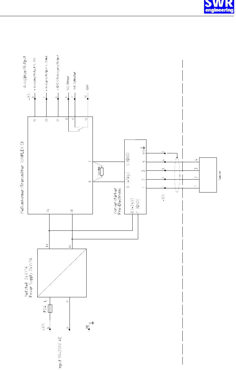
5.4 Flow diagram of the compact version
Commissioning
Page 15
6. Commissioning
6.1 Adjustment of pre-amplifier
For start-up the measurement system it is necessary to adjust the pre-amplifier to the local conditions.
After switching on the power supply there is at least a warm-up time of 15 minutes required before any
adjustments starts.
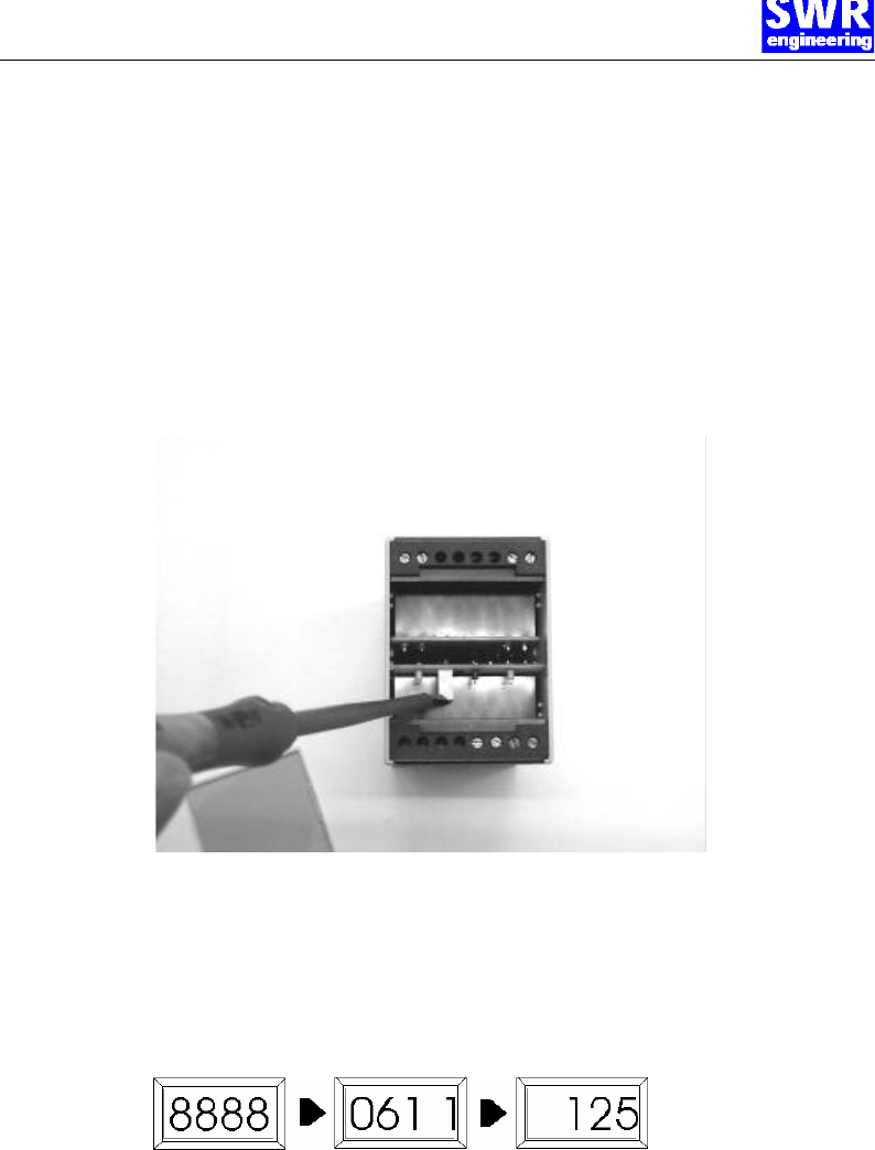
Set the flow rate in the duct to the maximum rate. Open the cover plate of the pre-amplifier and look for
the variable resistor P1. Now change the value which is displayed at the evaluation unit into a range
between 3-4 by turning left or right at the variable resistor. Alternative you can measure the voltage
range 3-4 Volt/DC direct at the terminal no. 5 + 6 at the pre-amplifier. In case that an adjustment is
impossible please check once more again;
• The correct cabling between sensor and pre-amplifier and by the separated version the cable
connection to the evaluation unit.
• The correct adjustment of the wall thickness at the sensor.
6.2 Adjustment of evaluation unit
Then the following displays appear one after the other in the four-digit display of the evaluation unit (for
display and operational controls see section 7):
The first display shows the self-test, the second display shows the configuration menu, and the third
display already shows the measured value.
Furthermore the green LED of the power supply is on as well as the green LED of the evaluation unit if
the adjusted limiting value is not exceeded. If the limiting value is exceeded, the green and the red LEDs
are on.
It is necessary for the first commissioning to carry out a calibration of the measuring system. It is
sufficient to carry out a two-point-calibration (zero flow or lower reference value and maximum flow or
higher reference value).
Commissioning
Page 16
To do so, go on as follows:
Zero point calibration
The product flow in the duct is stopped for the zero point calibration. Take care that no flow can take
place (all valves closed etc.).
Adjustment on the evaluation unit:
Press the arrow key 6 for 5 seconds. The display now changes between CL and a value. Adjust the
value with the help of the arrow keys 65 to 0 (or lower reference value).
After 10 seconds the value is stored, the output signal was set to the value.
Maximum value calibration
A maximum or known flow rate (reference value) is adjusted in the tube for the maximum value
calibration.
Adjustment on the evaluation unit:
Press the arrow key 5 for 5 seconds. Now the display changes between CH and a value. Adjust the
value with the help of the arrow keys 65 to e.g. 100 or the reference value.
After 10 seconds the value is stored, the output signal was set to the value.
Reset to basic calibration parameters
To delete both calibration parameters press key 6 during approx. 15 seconds.
The following default values have been set by the manufacturer:
Configuration menu Con1: 0541 corresponds to:
measurement value alarm = N.C. contact
input voltage = -3...13 V
type of sensor = voltage
input circuit monitoring = upscale
Configuration menu Con2: 1101 corresponds to:
output current = 4...20mA
characterisation = with scaling
computing function = no
mains frequency suppression = 50 Hz
The section 7. Operation explains how the parameters output signal, limiting value and filter constant
can be adjusted.
With the adjustments described above, the measuring system is now ready for operation.
Operation
Page 17
7. Operation
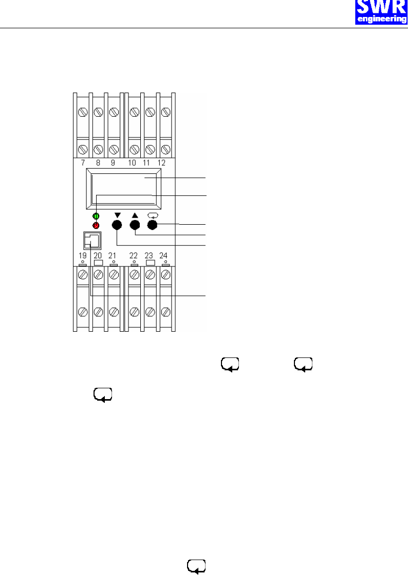
7.1 Operating elements
4.5-digit LC display
LED: red: indicator input circuit monitoring
green: indicator for supply voltage
Key: switch-over and confirmation
Key: increase value
Key: decrease value
4-pole connection for interface adapter
(optional)
Fig. 11: Operating elements of the evaluation unit
7.2 Adjusting the
output signal
Change to the configuration level by pressing for 5 sec. and once again for 5 sec.
Con1 is displayed.
Press another time and change to Con2.
Now adjust the value of Con2 by using the arrow keys 65 . The longer you press, the faster the
value changes. (The value of Con1 must not be changed).
The numbers in Con2 have the following meaning:
1st digit: mains frequency suppression:
0 = 50 Hz;
1 = 60 Hz
2nd digit: characterisation:
2 = with customised linearization
3rd digit: computing function:
0 = no computing function (e.g. extract roots etc.)
4th digit: output signal
0 = 0...20 mA;
1 = 4...20 mA,
2 = 0...10 V
The input is stored by pressing the key.
Note!
The two output signals (current and voltage) are available simultaneously.
This setting is used for selecting the output type, which shall be calibrated.
By selecting 0...20 mA, the voltage signal has a value of 0...10 V.
By selecting 4...20 mA, the voltage signal has a value of 2...10 V.
Operation
Page 18
7.3 Adjusting the parameters for the measurement value
alarm
Change to the parameter menu by pressing the key for 5 sec.
The values of the individual parameters are now adjusted with the help of the arrow keys 65. By
pressing the key, the next parameter is selected.
1. Parameter lower limiting value L_LI: selection range -999...9999 (physical unit of the display, pre-
selected range 0-100). Select a value within your selection range for the display. This function is
switched off by pressing the 6 key until "----" is displayed.
Change to the 2nd parameter by pressing .
2. Parameter higher limiting value L_HI: selection range 0...9999 (physical unit of the display). Select
a value within your selection range for the display. This function is switched off by pressing the 6
key until "----" is displayed.
Change to the 3rd parameter by pressing .
3. Parameter alarm hysteresis HYSI: selection range 0...9999. The alarm hysteresis determines the
delay with which alarm is given.
Change to the 4th parameter by pressing .
4. Parameter alarm time window dELI: selection range 0...9999 sec. The alarm time window sets an
alarm delay. If a limiting value is exceeded for a period shorter than the adjusted alarm time
window, it will be ignored.
Note!
The parameters for the limiting values can only be adjusted if the measurement value alarm was
configured in the configuration menu Con1. The parameter level is left after a time out of 30 sec., and
the adjusted values are stored.
7.4 Filter adjustments
Filter time constant
Change to the parameter menu by pressing for 5 sec.
Change to the display t _F filter time constant by pressing several times.
Adjust the filter time constant to the time, at which the signal variation is acceptable. Signal variations
which exceed the adjusted band width are output directly.
Filter band width
Change from the filter time constant r _F to the filter band width b _F by pressing the key.
The filter band width calculates a mean value if the signal value varies around a value. If the signal
variations are at e.g. 1.5%, the value for b _F is to be set at 1.5.
The parameter level is left after a time out of 30 sec., and the adjusted values are stored.

Maintenance / Warranty
Page 19
8. Maintenance
Warning!
Danger of shock with opened housing!
Switch off the supply voltage for all maintenance or repair works on the measuring system. The tube
must not be in operation during a sensor exchange.
Repair and maintenance work must be carried out by trained or expert personnel only.
The system is maintenance-free.
9. Warranty
Warranty is granted for two years starting from delivery date under the condition that
the operational instructions have been followed, no interventions on the appliances
have been made and the components of the system show no mechanical damage or
wear resistance.
In case of a defect during the warranty period, defective components are repaired or
are replaced free of charge. Replaced parts turn into the property of SWR. If desired
by the customer that the parts should be repaired or replaced in its factory, then the
customer has to take over the costs for the SWR-service staff.
SWR is not responsible for damage, which did not develop at the delivery article;
especially SWR is not responsible for escaped profit or other financial damages of the
customer.
Trouble shooting
Page 20
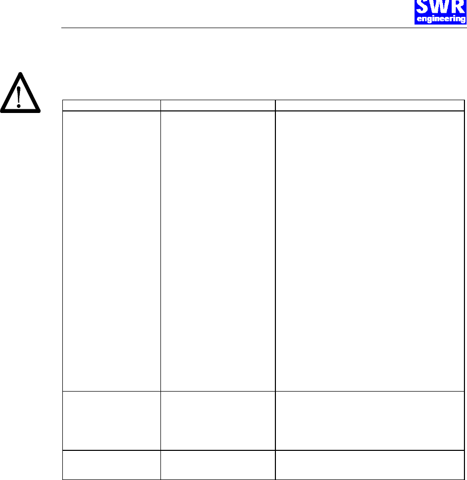
10. Trouble shooting
Warning!
The electrical installation must only be checked by expert personnel.
Problem Cause Measure
Measuring system does not
work. Power supply interrupted.
Break of a cable.
Fuse defective.
Device defective.
Check the power supply.
Check the connecting cables for a possible break
of a cable.
Exchange the fuse in the field housing (see fig. 9 +
10), 2A, fast.
compact version: Measure the following voltage values
on the terminals in the field housing.
Terminals 1 + 4: 24 V; if not measured, power supply
defective, exchange power supply.
Terminals 1 + 3: 8 V; if 24 V between 1 + 4 measured
but 8 V between 1 + 3 not measured, pre-amplifier
defective, exchange pre-amplifier.
Terminals 1 + 2: 2.5 V; 24 V and 8 V measured but 2.5 V
between 1 + 2 not measured, sensor defective,
exchange sensor.
separated version: Measure the following voltage
values on the terminals directly on the pre-amplifier in
the field housing.
Terminals 1 + 4: 24 V; if not measured, power supply
defective, exchange power supply.
Terminals 1 + 3: 8 V; if 24 V between 1 + 4 measured
but 8 V between 1 + 3 not measured, pre-amplifier
defective, exchange pre-amplifier.
Terminals 1 + 2: 2.5 V; 24 V and 8 V measured but 2.5 V
between 1 + 2 not measured, sensor defective,
exchange sensor.
Measuring system outputs
wrong values
Calibration not correct.
Calibration shifted by abrasion on
front end of sensor.
Delete input signal correction, press key 6 for
15 sec, and make a new calibration according to section
6.
Delete input signal correction, press key 6 for
15 sec, and make a new calibration according to section
6.
Relay flickering Hysteresis too small. Increase hysteresis, check effects caused by external
devices.
BA-0003-e-03/02 Page 21
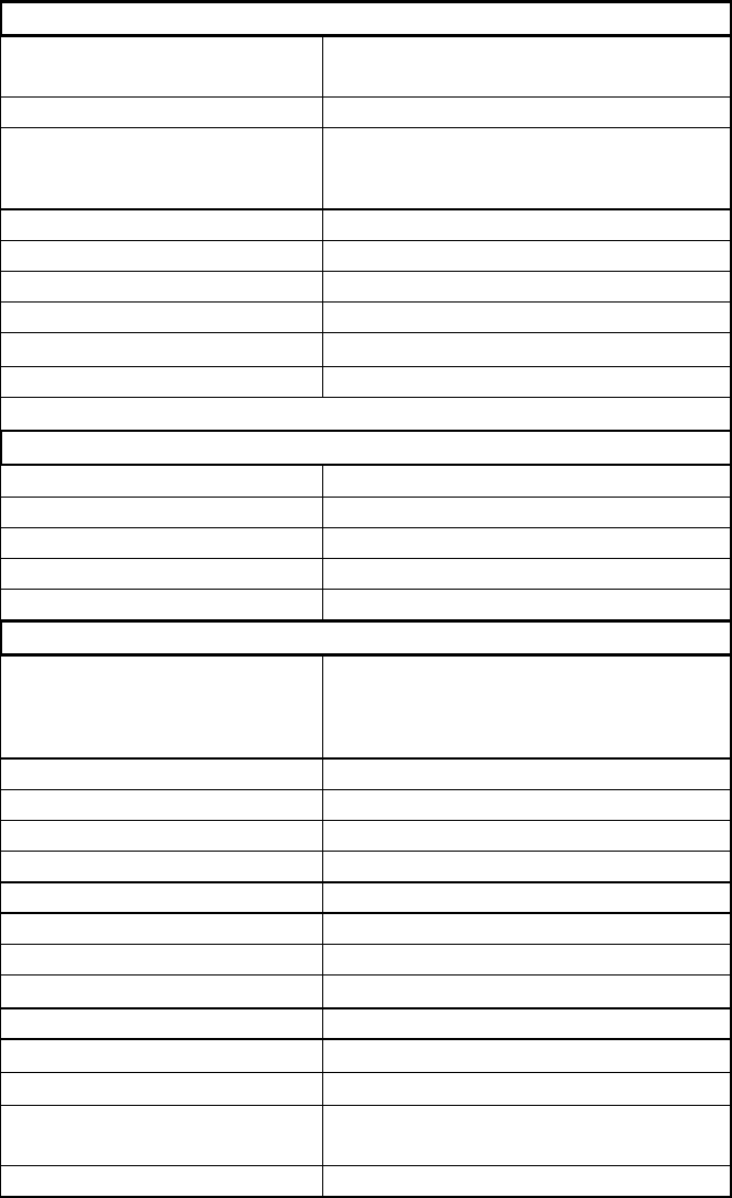
11. Technical Data
Sensor/Sensor accommodation
Housing Steel St52, galvanised
(stainless steel 1.4541 option)
Protection category IP65, DustEX 10 (option)
Operating temperature front end of sensor: -20....+ 80 °C [ -4...176 °F]
optional: -20...+200 °C [ -4...392 °F]
sensor electronic: 0....+ 60 °C [32...140 °F]
max. working pressure 1 bar, optional 10 bar
Working frequency K-Band 24.125 GHz, ±100 MHz
Transmitting power Max. 4 mW
Weight Approx. 1.3 kg
Dimension ∅ 60, Ø 20, L 290mm
Accuracy +/- 2..5% in calibrated range
Pre-Amplifier
Protection category IP65
Operating temperature –20...+60 °C [ -4...+140 °F]
Enclosure dimensions 200 x 200 x 120 mm (W x H x D)
Weight approx. 3.6 kg
Evaluation-Unit
Supply voltage 90...260 V AC, 47...440 Hz (with enclosed
power supply, regular)
or
24 V DC, -5/+15% (option)
Power consumption 24 W, 24 VA
Current consumption Max. 1 A @ 24 V
Protection category IP65 to EN 60 529/10.91
Operating temperature –10...+45 °C [14...113 °F]
Enclosure dimensions 300 x 400 x 155 mm (W x H x D)
Weight approx. 8.5 kg
Additional data:
Cable glands 3 x M16 (4.5 – 10 mm Ø)
Screw terminals 0.2 – 2.5 mm² [AWG 24-14]
Current output signal 4...20 mA (0...20mA), Load < 700 Ω
Voltage output signal 2…10 V (0…10V), Load > 2 kΩ
measurement value alarm relay
output Relay with switching contact
Max. 250V AC, 1A
Data storage EEPROM