SYM Technology V308919 Bi-Directional Amplifier User Manual Revised Vision30
SYM Technology, Inc. Bi-Directional Amplifier Revised Vision30
Users Manual

Usermanualforsoftwaredefinablerepeater
Network Vision
PassionfortheMission

UsermanualforSoftwareDefinableRepeater
ProprietaryandStrictlyConfidential1
User Manual for Vision30
<SoftwareDefinableRepeater>
Copyright©2012SYMTechnologyIncorporated.Allrightsreserved.
ThisproductisintendedonlyforinstallationinaRESTRICTEDACCESSLOCATIONandisdesigned
tooperatewithintheNormalOperating(typicaloperating)rangesorconditionsspecifiedinthis
document.Operationofthisequipmentbeyondthespecifiedrangesinthisdocumentmaycause:
1.Spuriousemissionsthatviolateregulatoryrequirements.
2.Theequipmenttobeautomaticallyremovedfromservicewhenmaximumthresholdsare
exceeded.
3.Theequipmenttonotperforminaccordancewithitsspecifications.
Itistheoperator'sresponsibilitytoensurethisequipmentisproperlyinstalledandoperated
withinSYMTechnologyoperatingspecificationstoobtainproperperformancefromthe
equipmentandtocomplywithregulatoryrequirements.
ForPERMANENTLYCONNECTEDEQUIPMENT,areadilyaccessibledisconnectdeviceshallbe
incorporatedinthebuildinginstallationwiring.
Document No.:
Date:
August 17, 2012 Version: 2.3
UserManual forVision30
Copyrightⓒ2012SYMTechnology,Inc.Allrightsreserved.
2
Warnings,Cautions,andNotes
Warnings,Cautions,andNotesarefoundthroughoutthismanualwhereapplicable.Theassociated
iconsareusedtoquicklyidentifyapotentialconditionthatcouldresultintheconsequencesdescribed
belowifprecautionsarenottaken.Notesclarifyandprovideadditionalinformationtoassisttheuser.
WARNING:Thiswarningsymbolmeansdanger.Youareinasituationthatcouldcause
bodilyinjury.Beforeyouworkonanyequipment,beawareofthehazardsinvolved
withelectricalandRFcircuitryandbefamiliarwithstandardpracticesforpreventing
accidents.
Toreducetheriskoffireorelectricshock,donotexposethisappliancetorainor
moisture.Workingwiththerepeaterwhileinoperation,mayexposethetechnicianto
RFelectromagneticfieldsthatexceedFCCrulesforhumanexposure.
CAUTION:Thiscautionsymbolmeansusertobecareful.Inthissituation,theusermight
dosomethingthatcouldresultinequipmentdamageorlossofdata.
Usetheattachedspecifiedpower‐suplycord.Ifanyanotherunapprovedcordisused,it
maycauseinterferencetotheequipment.Topreventelectricshock,donotuseother
plugwithanextensioncord.
NOTE:Thisnotesymbolmeansusertotakenote.Notescontainhelpfulsuggestionsor
referencestomaterialnotcoveredinthedocument.Proceduresarenotcontainedin
notes.
Informationinthisdocumentissubjecttochangewithoutnotice.
Pleasesendcommentsto:
E‐Mail:support@symtechnology.com
Phone:(626)356‐0817
Fax:(626)356‐9087
Address:SYMTechnology,Inc.
234E.ColoradoBlvd.,Suite410
Pasadena,CA91101,USA
http://www.symtechnology.com
UsermanualforSoftwareDefinableRepeater
ProprietaryandStrictlyConfidential3
RevisionHistory
DateVersionApprovalDescription
FEB.3,20121.0DocumentRelease
FEB.22,20121.1WebGUIchange
APR.1,20122.0EnclosureandServiceCardhardwarechange
July18,20122.1UsermanualtitlechangedintoVision30
July24,20122.2Safetyinstructionadded
Aug17,20122.3Photosarereplaced

Document No.:
Date:
August 17, 2012 Version: 2.3
UserManual forVision30
Copyrightⓒ2012SYMTechnology,Inc.Allrightsreserved.
4
TableofContents
Warnings,Cautions,andNotes......................................................................................................2
RevisionHistory..............................................................................................................................3
1.Introduction.............................................................................................................................8
1.1ProductDescription......................................................................................................................8
1.2ContentsofBox.............................................................................................................................9
1.3GlanceattheVision....................................................................................................................11
1.4SystemConfigurationandTechnical...........................................................................................11
2.Installation.............................................................................................................................18
2.1UnpakingandInspection............................................................................................................18
2.2InstallationConsiderations.........................................................................................................18
2.3WallMountingProcedure...........................................................................................................21
2.4RackMountingProcedure...........................................................................................................22
2.5ElectricalInstallation...................................................................................................................25
2.5.1Grounding............................................................................................................................25
2.5.2ConnectionoftheAntennaCables......................................................................................26
2.5.3ACPowerConnection..........................................................................................................27
2.5.4EthernetConnection............................................................................................................27
3.Operation...............................................................................................................................29
3.1SystemIndicators........................................................................................................................29
3.1.1SystemStatusIndicators......................................................................................................29
3.1.2ControllerStatusIndicators.................................................................................................30
3.2Initialstart‐upandpowersettingprocedures............................................................................31
3.2.1800/900MHzPowerSettingProcedures.............................................................................31
3.2.21900MHzPowerSettingProcedures..................................................................................32
3.3Web‐basedGUIoperation..........................................................................................................33
3.3.1NetworkConnection............................................................................................................34
3.3.1.1LocalNetworkConnection ........................................................................................... 34
3.3.1.2SprintPrivateNetwork ................................................................................................. 35

UsermanualforSoftwareDefinableRepeater
ProprietaryandStrictlyConfidential5
3.3.2WebbasedGUILogin...........................................................................................................35
3.3.3MenuList.............................................................................................................................36
3.3.4Status...................................................................................................................................37
3.3.4.1Gauge ............................................................................................................................ 37
3.3.4.2Band&GainControl ..................................................................................................... 38
3.3.5Health..................................................................................................................................38
3.3.5.1AlarmStatusMonitoringforServiceCard .................................................................... 39
3.3.5.2SettingAlarmThreshold ............................................................................................... 39
3.3.5.3EventLog ...................................................................................................................... 40
3.3.5.4SNMPTestAlarm .......................................................................................................... 40
3.3.5.5Input&OutputGraph .................................................................................................. 40
3.3.6Setup....................................................................................................................................41
3.3.6.1Network ........................................................................................................................ 41
3.3.6.2Install&Update ............................................................................................................ 43
3.3.7Account................................................................................................................................46
3.3.7.1UserList ........................................................................................................................ 46
3.3.7.2NewAccount ................................................................................................................ 48
3.3.8MemoPad............................................................................................................................48
3.3.9OtherMiscellaneousFeatures.............................................................................................49
4.Maintenance..........................................................................................................................50
4.1Troubleshooting..........................................................................................................................50
4.2ReplacementofComponents.....................................................................................................52
4.2.1FieldReplaceableUnits(FRU)..............................................................................................53
4.2.2800/900MHzServiceCard...................................................................................................53
4.2.31900MHzServiceCard........................................................................................................54
4.2.4Rectifier................................................................................................................................55
4.2.5Controller.............................................................................................................................56
4.3ReturnforServiceProcedures....................................................................................................57
5.Specifications.........................................................................................................................59
5.1800/900MHzServiceBand.........................................................................................................59
5.21900MHzServiceBand..............................................................................................................60

Document No.:
Date:
August 17, 2012 Version: 2.3
UserManual forVision30
Copyrightⓒ2012SYMTechnology,Inc.Allrightsreserved.
6
ListofFigures
[Figure1‐1]PartsListforVision................................................................................................................10
[Figure1‐2]GlanceattheVision...............................................................................................................11
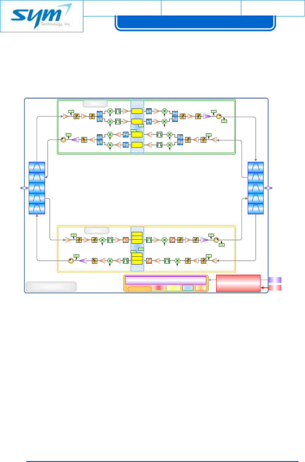
[Figure1‐3]BlockDiagramforVision........................................................................................................12
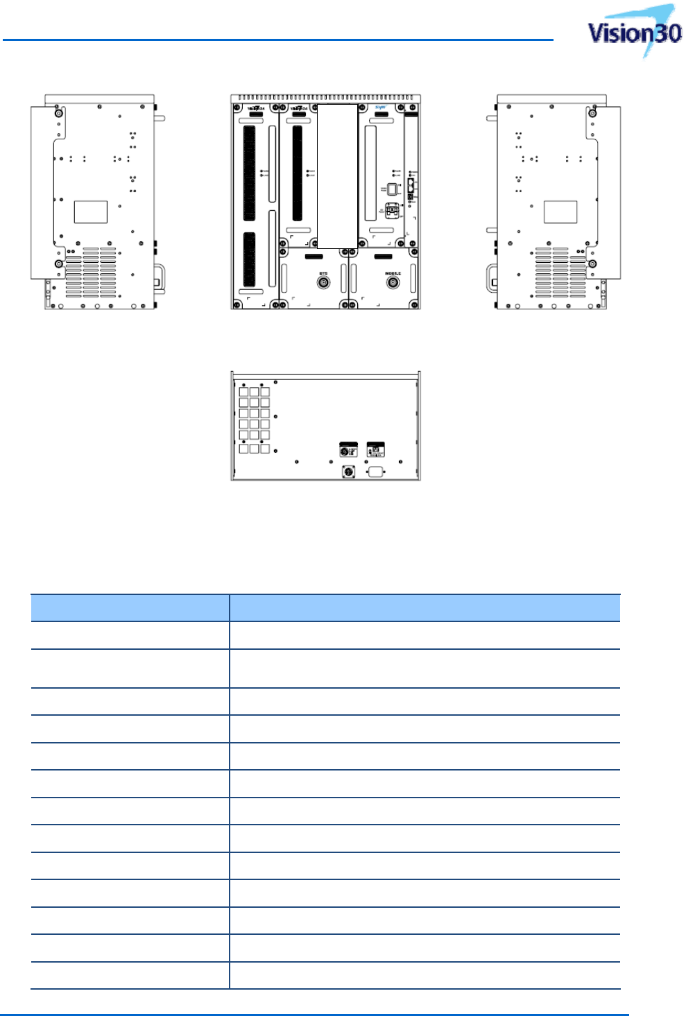
[Figure1‐4]MechanicaldimensionforVisionplatform...........................................................................13
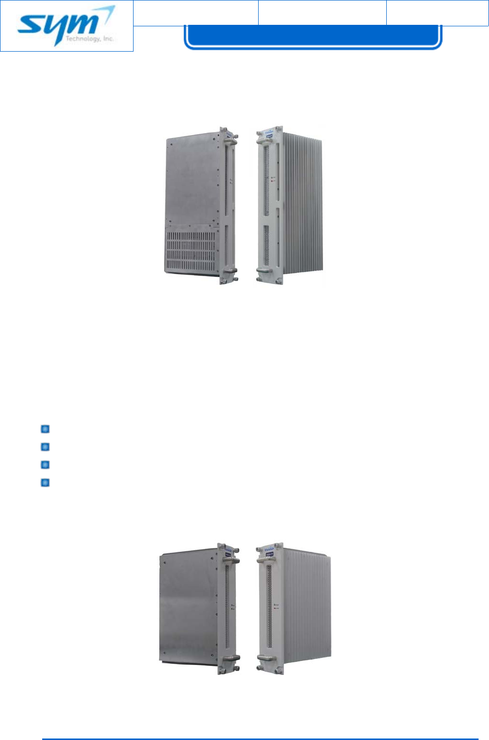
[Figure1‐5]800/900MHzServiceCardview............................................................................................14
[Figure1‐6]1900MHzServiceCardview.................................................................................................14
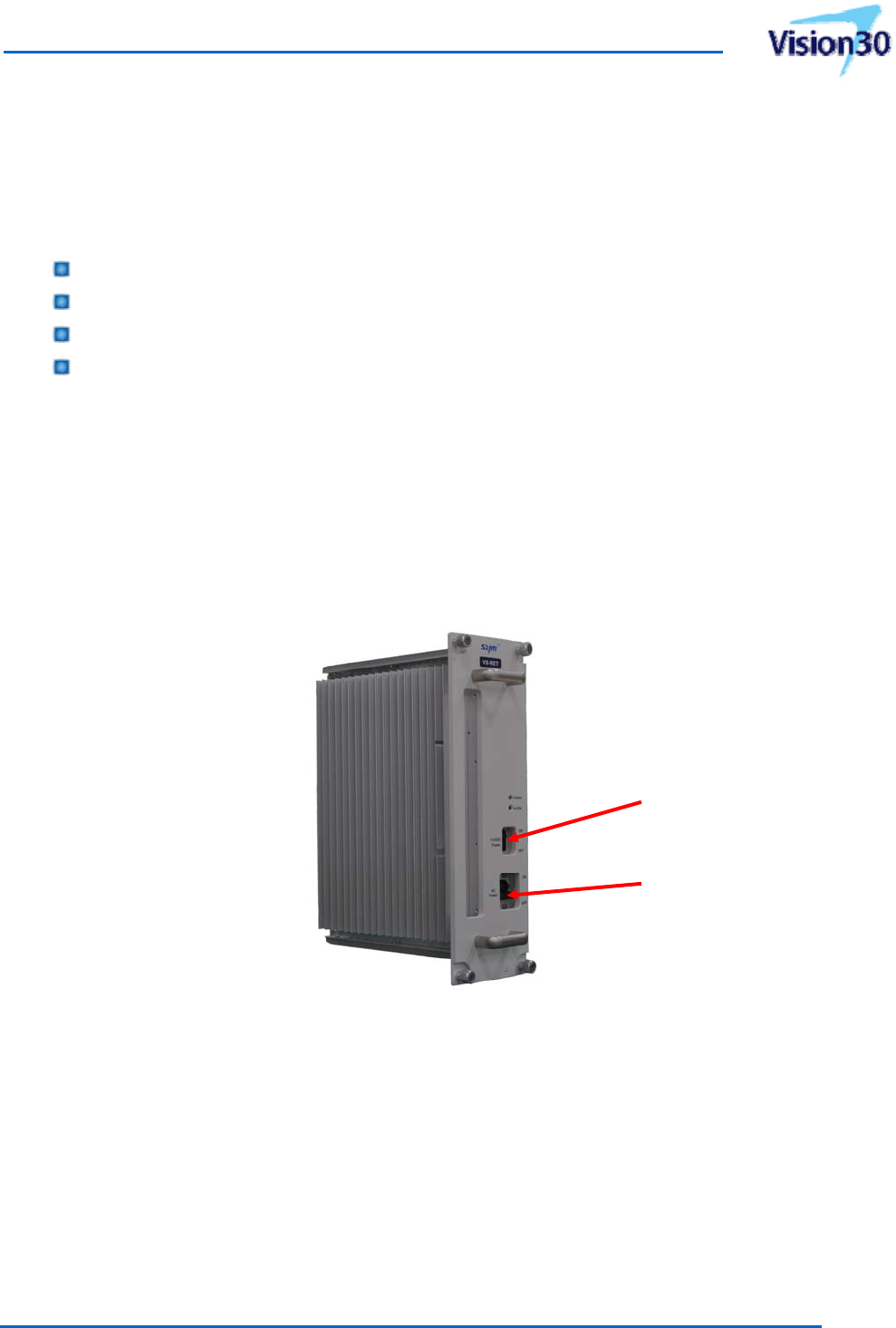
[Figure1‐7]Rectifierview.........................................................................................................................15
[Figure1‐8]Controllerview.......................................................................................................................16
[Figure1‐9]Filter&Combinerviews..........................................................................................................16
[Figure1‐10]MainFramefrontandrearviews........................................................................................17
[Figure2‐1]WallMountBracketDimension.............................................................................................20
[Figure2‐2]RackMountDimensionDrawings..........................................................................................20
[Figure2‐3]Wallmountinginstallation.....................................................................................................22
[Figure2‐4]Rackmountinginstallation....................................................................................................23
[Figure2‐5]Groundingcableconnection..................................................................................................25
[Figure2‐6]AntennaportontheVision...................................................................................................26
[Figure2‐7]ACpowerinputsocketontheVision....................................................................................27
[Figure2‐8]EthernetportontheVision...................................................................................................28
[Figure2‐9]WANportconnectiontoanUWMS‐01.................................................................................28
[Figure3‐1]FrontPanel..........................................................................................................................29
[Figure3‐2]ControllerFrontPanelControlsandIndicators.....................................................................30
[Figure3‐3]LocalAreaConnectionProperties..........................................................................................34
[Figure3‐4]InternetProtocolProperties..................................................................................................35
[Figure3‐5]WebGUILogin.......................................................................................................................35
[Figure3‐6]WebGUIMainMenu.............................................................................................................36
[Figure3‐7]ServiceBandStatus................................................................................................................37
[Figure3‐8]StatusPage.............................................................................................................................38
[Figure3‐9]HealthPage............................................................................................................................39
[Figure3‐10]EventLogPop‐up.................................................................................................................40
[Figure3‐11]NetworkPage.......................................................................................................................41

UsermanualforSoftwareDefinableRepeater
ProprietaryandStrictlyConfidential7
[Figure3‐12]Install&Upgradepage.........................................................................................................43
[Figure3‐13]InstallationWizardviaStep1..............................................................................................44
[Figure3‐14]InstallationWizardviaStep2..............................................................................................44
[Figure3‐15]InstallationWizardProcessviaStep3.................................................................................45
[Figure3‐16]FirmwareUpdate.................................................................................................................45
[Figure3‐17]FactorySet...........................................................................................................................46
[Figure3‐18]UserListPage.......................................................................................................................47
[Figure3‐19]NewAccountPage...............................................................................................................48
[Figure3‐20]MemoPage..........................................................................................................................49
[Figure4‐1]800/900MHzServiceCardReplacement...............................................................................54
[Figure4‐2]1900MHzServiceCardReplacement....................................................................................55
[Figure4‐3]RectifierReplacement............................................................................................................56
[Figure4‐4]ControllerReplacement.........................................................................................................57
ListofTables
[Table1‐1]PartsListforVision30(VS30‐F‐KIT)...........................................................................................9
[Table1‐2]MechanicalandEnvironmentalCharacteristics......................................................................13
[Table2‐1]Toolsneededforinstallation(notsupplied)............................................................................19
[Table3‐1]SystemStatusIndicators..........................................................................................................29
[Table3‐2]ControllerStatusIndicators.....................................................................................................30
[Table3‐3]DLGainsettingofDownlinkinputpowerincaseofV30‐89(30dBmmodel).........................32
[Table3‐4]DLGainsettingofDownlinkinputpowerincaseofV30‐19(30dBmmodel).........................33
[Table3‐5]WebGUIAccessID/Password..................................................................................................36
[Table3‐6]WebGUIMainMenu...............................................................................................................36
[Table3‐7]AlarmStatusforHealthPage...................................................................................................39
[Table3‐8]EventLogDescription..............................................................................................................40
[Table3‐9]UserGroupAccessAuthority...................................................................................................47
[Table4‐1]LEDIndicatorsTroubleshootingguide.....................................................................................50
[Table4‐2]SystemAlarmontheWebGUITroubleshootingguide...........................................................51
[Table4‐3]FieldReplaceableUnits...........................................................................................................53
[Table5‐1]800/900MHzServiceBandSpecifications...............................................................................59
[Table5‐2]1900MHzServiceBandSpecifications....................................................................................60

Document No.:
Date:
August 17, 2012 Version: 2.3
UserManual forVision30
Copyrightⓒ2012SYMTechnology,Inc.Allrightsreserved.
8
1. Introduction
Thismanualcontainsinformationandproceduresforinstallation,operation,andmaintenanceofthe
Visionindoorsystem.
Thesystemisfuture‐proof,readyforevolutiontoadvancedmodulationschemeslikeEV‐DO
(evolution‐dataoptimized)andLTE(LongTermEvolution).ServiceCardsareavailableinsingle‐ormulti‐
bandconfigurationforavarietyoffrequencycombinations(3frequencybandssimultaneously),power
classes,andsystemdesigns.
1.1 ProductDescription
TheVisionplatformisaplug‐and‐playrepeatersolutionthatutilizesthemediumpowerand
performanceforaonesectormulti‐carriersolution.TheVisionprovidesadjustabledownlink
power/gain,adjustableuplinkpower/gain,downlinkanduplinksignalconditioning,optionalremote
systemstatusmonitoringandremotesystemconfigurabilityviaexternalwirelessmodem.
TheVisionisanin‐buildingRFrepeatersystemandcoversSMR800MHz/900MHzandCDMA/LTE
1900MHzbandssimultanelosuly.TheVisioncanprovidesignalcoverageandhighquality,fastdata
transmission.
TheVisionhastwoservicecardswhichare800/900MHzcardand1900MHzcard.Thesecardsarebi‐
directionalamplifierunitsforeachband.AndtheVisionhasrectifierandcontrollercardaswell.All
servicecardsaremountedthroughbackboardwhichislocatedinthemainframeenclosure.AllRF
cablesarepre‐installedbetweenbackboardandfilter&combinerunits.Filter&combinerunitsprovide
commonantennacableconnectionforallsignals.
800/900MHzservicecardand1900MHzservicecardincludedigitalfiltertoselectmultiplesub‐
bands(orblocks)easily.WhenprovidingLTEserviceinsteadofiDEN/CDMA,VisoncanprovideLTE
servicewithoutanyhardwarechangeasitonlyrequiresnewbandwithselectionforLTEsignal.The
Visionplatformisdesignedtoaccommodateavarietyandamixtureofdifferentandupcoming
technologies.
TheControllerofVisionsystemhasthelocalmanagementabilitytocontrolandmonitorthestatusof
therepeaterandalsoprovidesremotemonitoringandcontrollingcapabilityviaexternalwireless
modem.

UsermanualforSoftwareDefinableRepeater
ProprietaryandStrictlyConfidential9
HerearethekeyfeaturesoftheVision.
Triple‐BandConfigurationwithSelectableMultipleSub‐bands(800/900/1900MHz)
ModularDesignwithHotSwappableCards(accommodatingupto2cards)
DigitalFilteringusingHighPerformanceDSP
Multi‐standardplatformistechnologyagnostic(iDEN/CDMA/LTE)
InstallationWizard:AutomaticInstallationandOptimization
Filter&CombinerUnitsforCommonDonorandSeviceAntennas
WirelessSetupviaWi‐Fi
DownlinkInput&OutputPowerTrendDisplay(48hours)
UserFriendlyWeb‐basedGUI
ConvectionCooling(NoFAN)
SlimBodyStructure
1.2 ContentsofBox
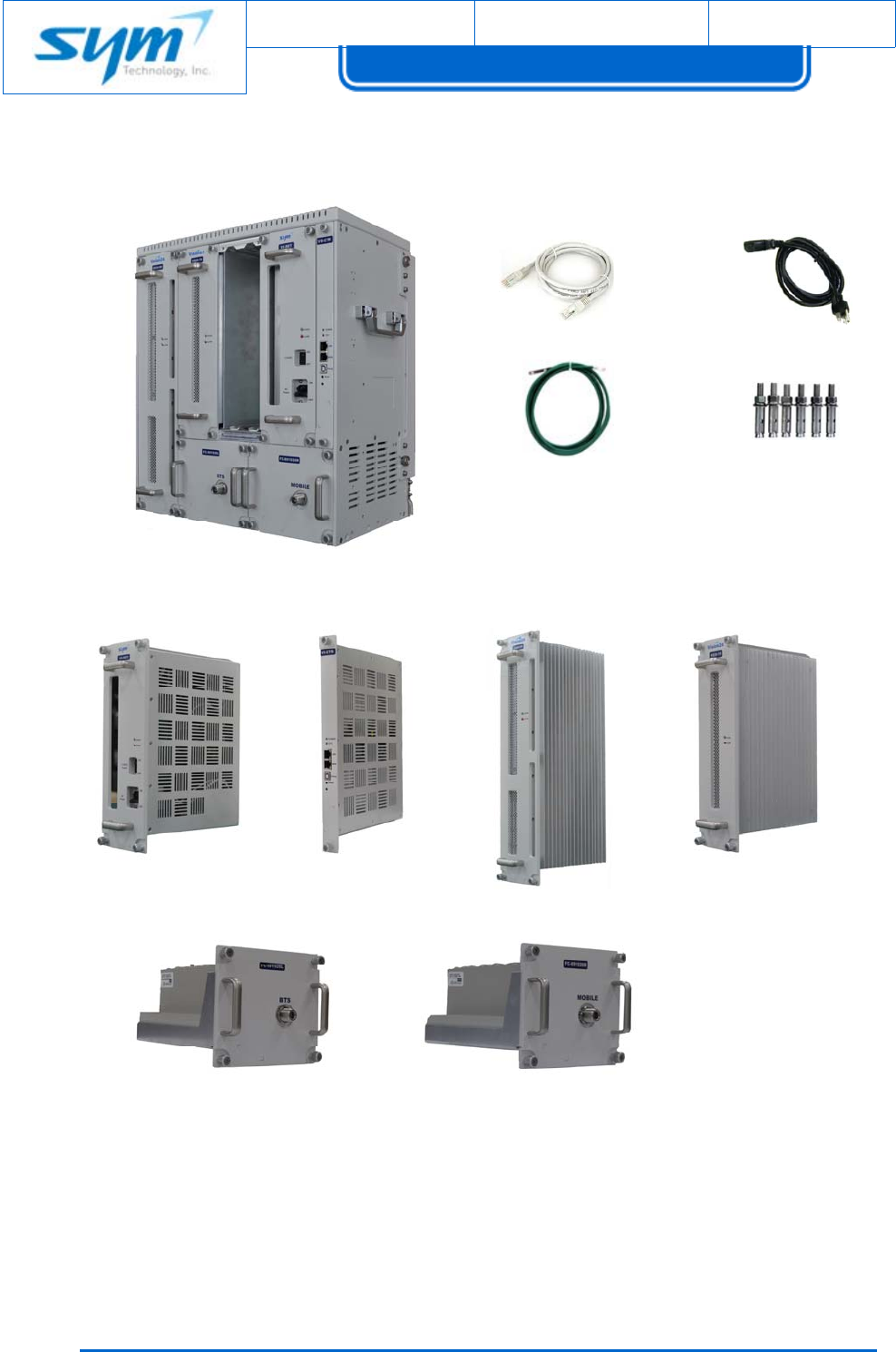
[Table1‐1]PartsListforVision30(VS30‐F‐KIT)
NoItemPartNumberQty
1VisionMainFramewithFilter,RF
CablesandwallmountbracketVS‐MF1
2EthernetCable6.6ft(2m)VS‐EC011
3PowerCord5.9ft(1.8m)VS‐PC011
4GroundCable6.6ft(2m)VS‐GC011
5WallMountingScrewsVS‐MB016
6RectifierVS‐RET1
7ControllerVS‐CTR1
830dBm,800/900MHzServiceCardV30‐891
930dBm,1900MHzServiceCardV30‐191
10Filter&CombinerforDonorAntenaFC‐891926L1
11Filter&CombinerforServiceAntenaFC‐891926R1
Document No.:
Date:
August 17, 2012 Version: 2.3
UserManual forVision30
Copyrightⓒ2012SYMTechnology,Inc.Allrightsreserved.
10
[Figure1‐1]PartsListforVision
(1)(2)(3)
(4)
(6)(7) (8)(9)
(5)
(10)(11)
UsermanualforSoftwareDefinableRepeater
ProprietaryandStrictlyConfidential11
1.3 GlanceattheVision
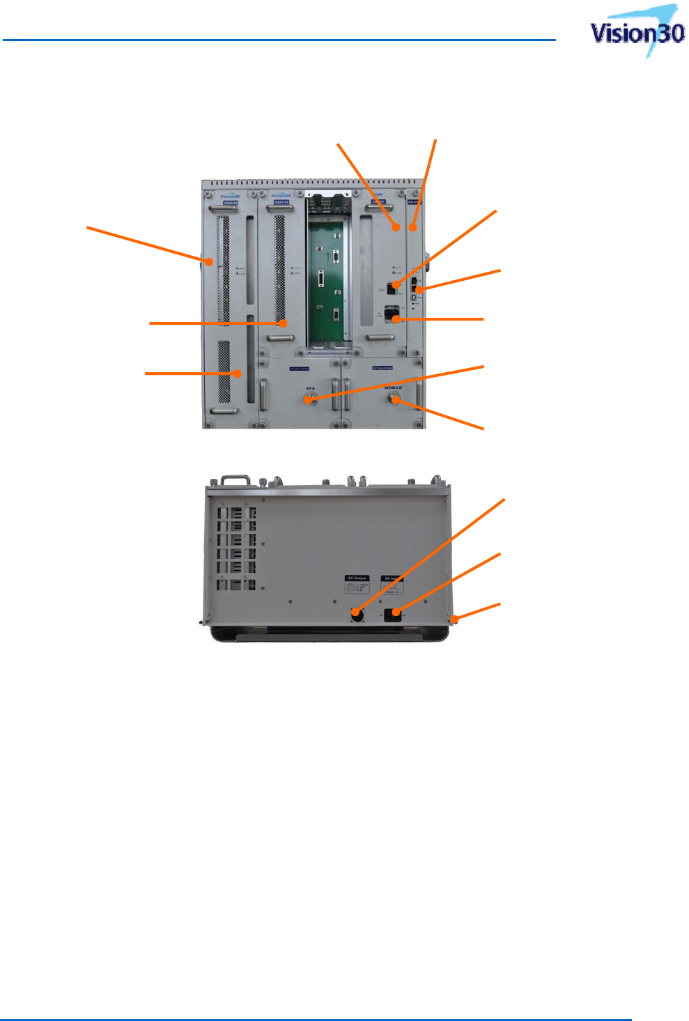
[Figure1‐2]GlanceattheVision
1.4 SystemConfigurationandTechnical
ThephysicalsizeandenclosureofVisionplatformhasbeenoptimizedforeaseofinstallation.The
systemissuppliedwithaheatsinktodissipateheatfromthesystem.Thesystemisdesignedto
withstanditsweightwhenperformingwallmountinginstallationandalsoprovidesrackmountbrackets
toaccommodateinstallationonstandard19”rack.TheVisionenclosureincludesonerectifier(120VAC
/60Hz),onesystemcontroller,andfilter&combinerunits.TheIP20indoorratedenclosurehasasturdy
aluminumframeasshownin[Figure1‐2].
TheVisionplatformisdesignedwithseparateservicecardswheretheusercanservicealltwocards
800/900MHzServiceCard
1900MHzServiceCard
RectifierController
Donor(BTS)
AntennaPort
Service(MOBILE)
AntennaPort
Handle
+12VDCPower
On/Offswitch
ACPower
On/Offswitch
+12VDCOutputPort
ACInputPort
EarthGroundLug
EthernetPorts
forLAN/WAN
Document No.:
Date:
August 17, 2012 Version: 2.3
UserManual forVision30
Copyrightⓒ2012SYMTechnology,Inc.Allrightsreserved.
12
tosimultaneously(iDENandCDMA/LTEnetwork)ormayjustserviceoneparticularnetwork.Each
servicecardhasonemodularizeddownlinkanduplinkconverterwithpoweramplifiertominimizethe
physicalsizeandincreaseefficiency.
DET
LNA
FIR1
SAW
Server
Port
HPA DET
DET
LNA
FIR1
Digital
LNA
FIR1
HPA
DET
DET
Digital
800/900
SAW
SAW LNA
HPA
DET
SAW
Quad-band
VisionTM Series
Donor
Port
DL
UL
DL
UL
DL
UL
DL
UL
DHCP, Web server, SNMP
Ethernet USB LEDs
CONTROLLER
DL Input
UL Output
FIR2
FIR2
DET
SAW
SAW
HPA
DET
DET
DET
AC IN
Craft
Rectifier
(POWER SUPPLY UNIT)
DET
DET
DET
DET
LO2 LO2
LO1 LO1
Fix LO1 Fix LO1
Fix LO2 Fix LO2
Fix LO3 Fix LO3
Fix LO4 Fix LO4
FIR2
FIR3
FIR1
FIR2
FIR3
1900
MPX MPX
UL Input
DL Output
WiFi
[Figure1‐3]BlockDiagramforVision
UsermanualforSoftwareDefinableRepeater
ProprietaryandStrictlyConfidential13
[Figure1‐4]MechanicaldimensionforVisionplatform
[Table1‐2]MechanicalandEnvironmentalCharacteristics
ItemDescription
Dimenstions(W*H*D)17.4*19.6*10inch(442*498*254mm)
Weight90.6lbswhenfullyloadedwithan800/900card(15.4lbs)
and1900card(12.6lbs)
CoolingConventionalCooling(NoFAN)
ACPower110~125VAC,60Hz
OperatingTemperature+14°Fto+122°F(‐10°Cto+50°C)
RelativeHumidity5%to95%non‐condensing
RFconnectorsN‐typefemale(BTSandMOBILEports)
EthernetInterfaceRJ‐45jack(LANandWAN)
12VDCOutputConnectorCircularReceptacle(206430‐1)
EarthGroundLugCopperCompressionTerminal(7/8”twohole)
MountingMethodWallMountand19”RackMount
CertificatesUL60950‐1,FCCpart15,part90andpart24
EnvironmentalRoHScompliant(EUDirective2002/95/EC)
Document No.:
Date:
August 17, 2012 Version: 2.3
UserManual forVision30
Copyrightⓒ2012SYMTechnology,Inc.Allrightsreserved.
14
1.4.1. 800/900MHzServiceCard
[Figure1‐5]800/900MHzServiceCardview
The800/900MHzservicecardconsistsofup/downconverterwithinternalpoweramplifier,digital
filtermodulebasedonhigh‐performanceFPGA.
Thefollowingarethekeyfeaturesof800/900MHzservicecard.
VeryflexibleBandwidth:0.25MHzto18MHz(by0.25MHzstep)
OneClickFrequencyShifting:200kHzBandShifting
Support2Non‐contiguousSub‐bands
CenterFrequencyisadjustableby25KHzstepforEachSub‐band
1.4.2. 1900MHzServiceCard
[Figure1‐6]1900MHzServiceCardview
UsermanualforSoftwareDefinableRepeater
ProprietaryandStrictlyConfidential15
The1900MHzservicecardconsistsofup/downconverterwithinternalpoweramplifier,digitalfilter
modulebasedonhigh‐performanceFPGA.
Thefollowingarethekeyfeaturesof1900MHzservicecard.
VeryflexibleBandwidth:1.25MHzto20MHz(by1.25MHzstep)
Support3Non‐contiguousSub‐bands
CenterFrequencyisadjustableby50kHzstepforEachSub‐band
MaximumInstantaneousBandwidth:upto60MHz
1.4.3. Rectifier
TheRectifierisdesignedtotakeACpowerandsupplyallnecessarypowerthroughoutthesystemand
usesonlyindustrialgradecomponents.
Ittakesin110~125VACandconvertsto3.5VDC,6.5VDC,12VDCand28VDCanddistributes
necessaryDCpowertoeachmoduleofthesystem.
[Figure1‐7]Rectifierview
ACMainPower
Switch
+12VDCOuput
PowerSwitch
Document No.:
Date:
August 17, 2012 Version: 2.3
UserManual forVision30
Copyrightⓒ2012SYMTechnology,Inc.Allrightsreserved.
16
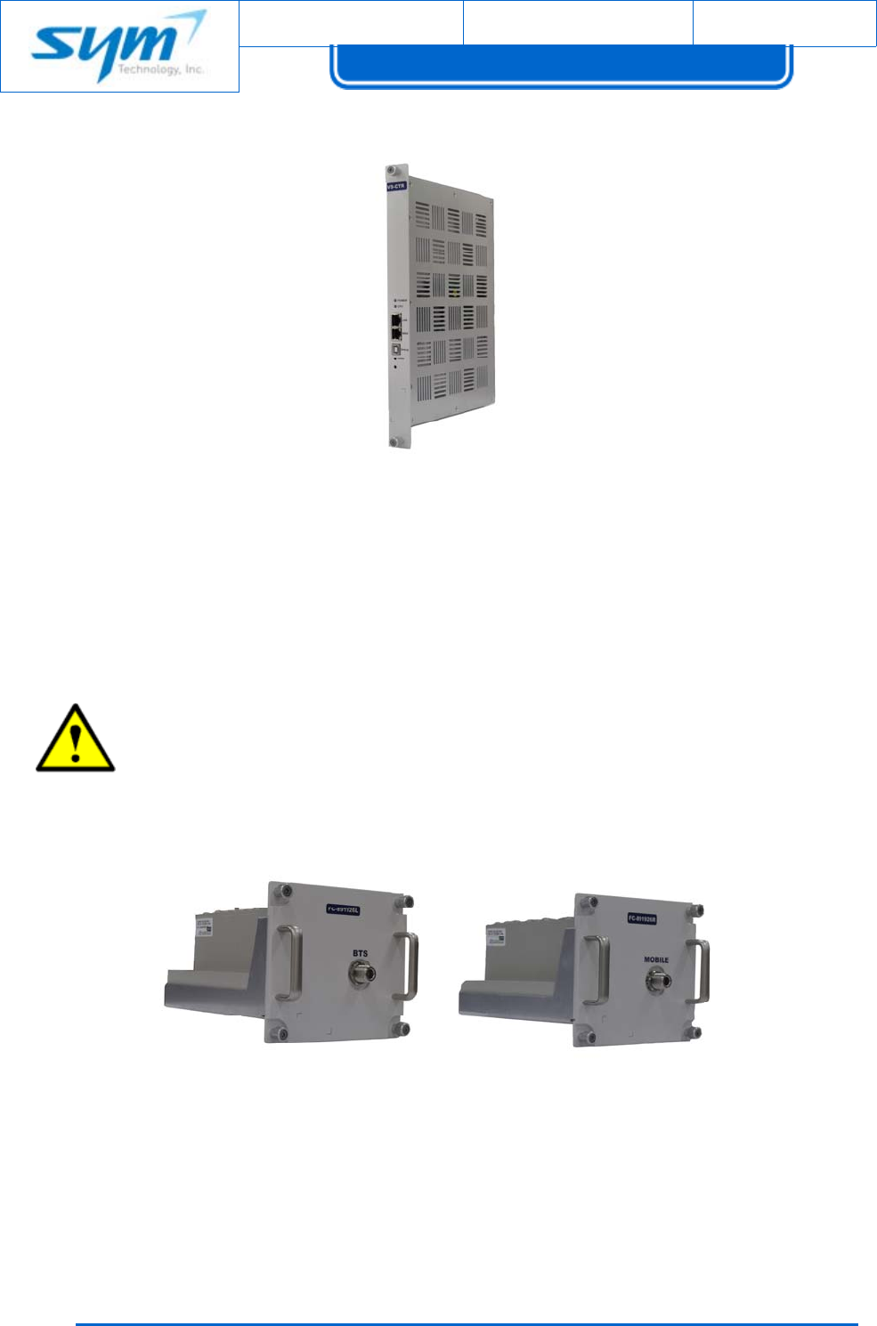
1.4.4. Controller
[Figure1‐8]Controllerview
ThemainfunctionalityofControlleristomonitorthestatusandcontroleachmoduleofthesystem
viaLANport(RJ‐45jack).TheLEDsonfrontpaneloftheControllordisplaytheoperationstatusofeach
servicecard.AndithasaWi‐FiAPmoduleinthecontroller,sothenitcansupportwirelesssetup
withoutconnectingactualEthernetconnection.
CAUTION:
LithiumBattery:Riskofexplosionifbatteryisreplacedbyanincorrecttype.Disposeof
usedbatteriesaccordingtotheinstructions.
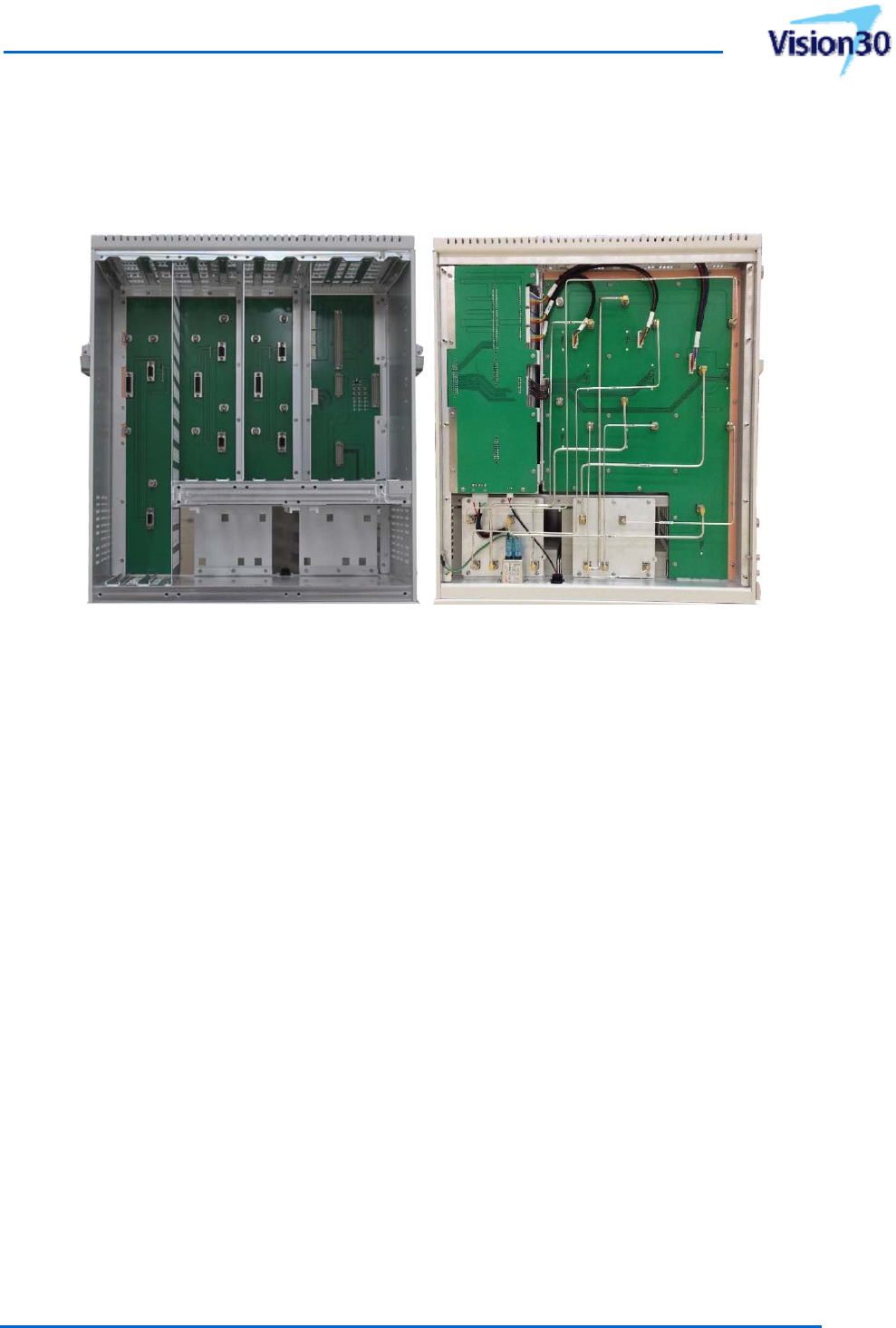
1.4.5. Filter&Combiner
Filter&CombinerforDonorAntennaFilter&CombinerforServiceAntenna
[Figure1‐9]Filter&Combinerviews
Therearenoantennaportsoneachservicecardofthesystem.Instead,allservicecardsarecombined
throughfilter&combinerunitsfordownlinkanduplink.ThismeanstheVisionsystemallowsyoutoput
amulti‐bandcombinerunittobeabletousemulti‐bandantennathroughonecombinedport.There
UsermanualforSoftwareDefinableRepeater
ProprietaryandStrictlyConfidential17
areoneFilter&CombinertotakesignalinputfromBTSviadonora`ntennaandtheother
Filter&CombinertodistributesignalstopassiveDAS(DistributionAntennaSystem)orserviceantenna.
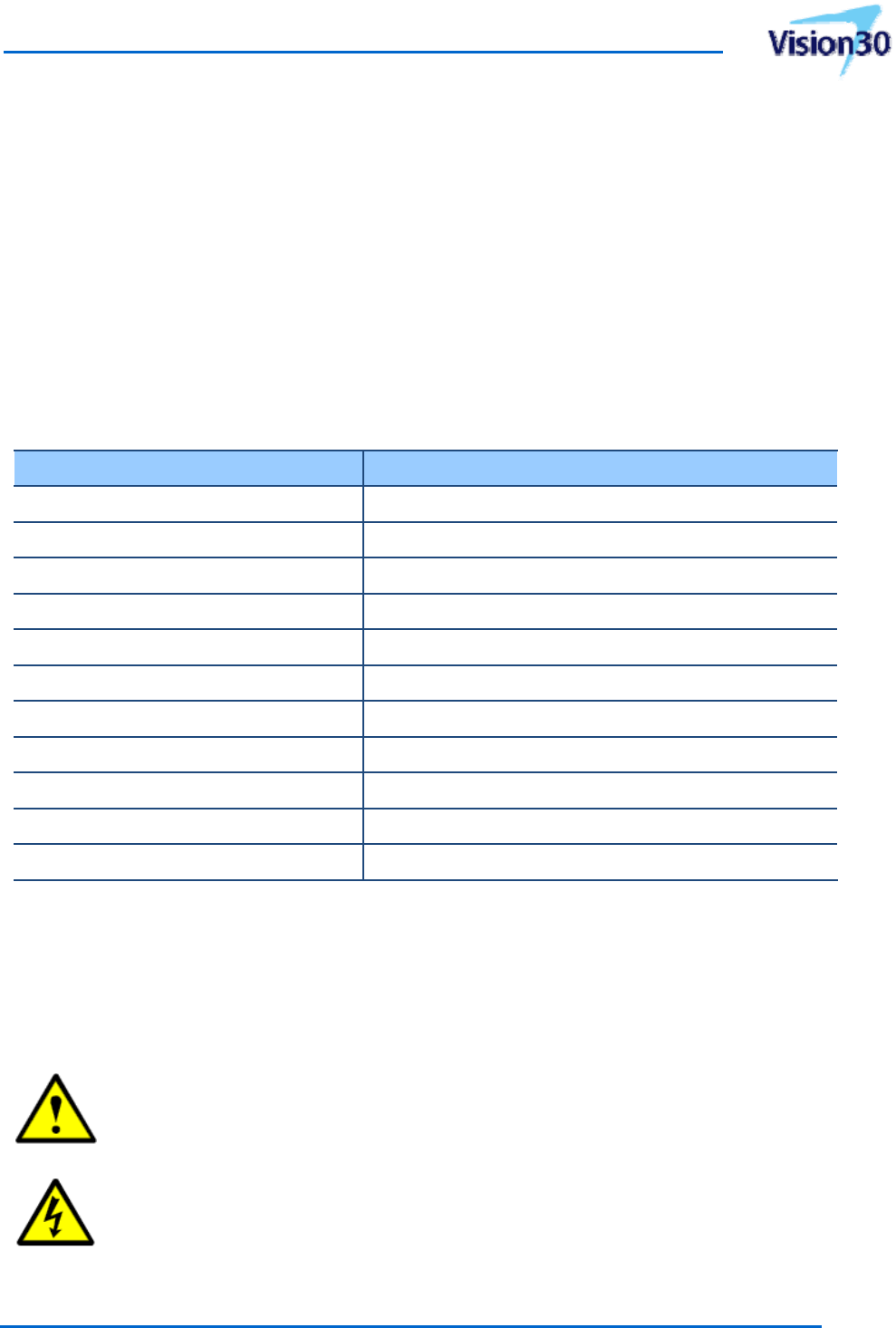
1.4.6. MainFrame
[Figure1‐10]MainFramefrontandrearviews
TheMainFrameincludesbackboardwhichcanhaveinterfacewithallservicecards,rectifier,controller
andfilter&combinerunits.RFcablesareprewiredontherearofthebackboard.Thishelpsuserinstall
allunitswithoutconnectinganyRFcablesexceptantennacables.

Document No.:
Date:
August 17, 2012 Version: 2.3
UserManual forVision30
Copyrightⓒ2012SYMTechnology,Inc.Allrightsreserved.
18
2. Installation
Thischaptercontainsunpacking,inspection,installationinstructions,andrecommendationsfor
installingtheVisionindoorsystem.
Itisimportanttoperformthefollowing:
Carefullyreadallmaterialinthischapterpriortoequipmentinstallation.
Reviewanygovernmentandlocalcodesastheyapplytoyourinstallation.
Beforeoperating,readtheinstructionsinchapter3.
SYMTechnologyrecommendsthatasitesurveybeperformedbyaqualifiedindividualorfirmprior
toequipmentorderingorinstallation.Performingadetailedsitesurveyreducesoreliminates
installationandturn‐updelays.PayparticularattentiontoACpoweravailability,spaceandRFcabling
required.
2.1 UnpakingandInspection
Thisequipmenthasbeenoperated,testedandcalibratedatthefactory.Carefullyopenthe
containersandremovetheequipment.Retainallpackingmaterialthatcanbereassembledintheevent
thattheunitmustbereturnedtothefactory.Pleaseperformthefollowingsteps:
Visuallyinspectfordamagethatmayhaveoccurredduringshipment.Ifpossible,inspectthe
equipmentinthepresenceofthedeliveryperson.
Checkforevidenceofwaterdamage,bentorwarpedchassis,loosescrewsornuts,or
extraneouspackingmaterialinconnectors.
Iftheequipmentisdamaged,thecarrieristhefirstareaofrecourse.Determinetheextentof
damageandthenfileaclaimwiththecarrier.
Iftheequipmentmustbereturnedtothefactory,pleaserefertochapter4.3forinformation
concerningaReturnMaterialAuthorization(RMA).
2.2 InstallationConsiderations
Environmentalconditionsoftheinstallationlocationshouldbewithinthesystemoperational
specifications.Ingeneral,areaswithgoodairflow,thusprovidingnaturalventilation
UsermanualforSoftwareDefinableRepeater
ProprietaryandStrictlyConfidential19
Normalinstallationrequires120VACsinglephaseinput.Specialconsiderationshouldbegivento
lightningprotectionofallsystemsinviewofthevulnerabilityofmosttransmittersitestolightning.
Lightningarrestorsarerecommendedintheserviceentrance.Straight,shortgroundrunsare
recommended.Theelectricalservicemustbewellgrounded.
TheVisionisdesignedforinstallationinlocationsthatpermitaccesstothebottomoftheenclosure
forconnectionofACinputpower,DCoutputpowerandRFcables.
[Table2‐1]liststhetoolsthattheinstallerneeds.Referto[Figure2‐3]and[Figure2‐4],formounting
examplesandmountingbrackets.
[Table2‐1]Toolsneededforinstallation(notsupplied)
ToolsneededWhereused
CrimptoolGroundcables
Electrician’sknifeEarthground
CableCutterGroundcables
RotoHammerWallMountingBracket
DrillBitWallMountingBracket
20mmOpen‐endwrenchTighteningandlooseningNconnectors
SlottedScrewdriverMountingBracketandEnclosure
SpectrumAnalyzer(800to3,000MHz)Systemperformancechecksandsettingoutputpower
30dB;50‐wattAttenuatorsSpectrumAnalysis
DigitalVolt‐OhmMeterVerifypower
RFCablesTestsetup
Mounttheenclosureontoitsdesignatedlocation.Verifythatsufficientspacetoslidethemodulesin
andoutisavailableandthattheairintakeandexhaustventsarenotblocked.Aminimumof8inches
(203mm)offreespaceisrequiredatboththetopandbottomoftheenclosuretoproperlycoolthe
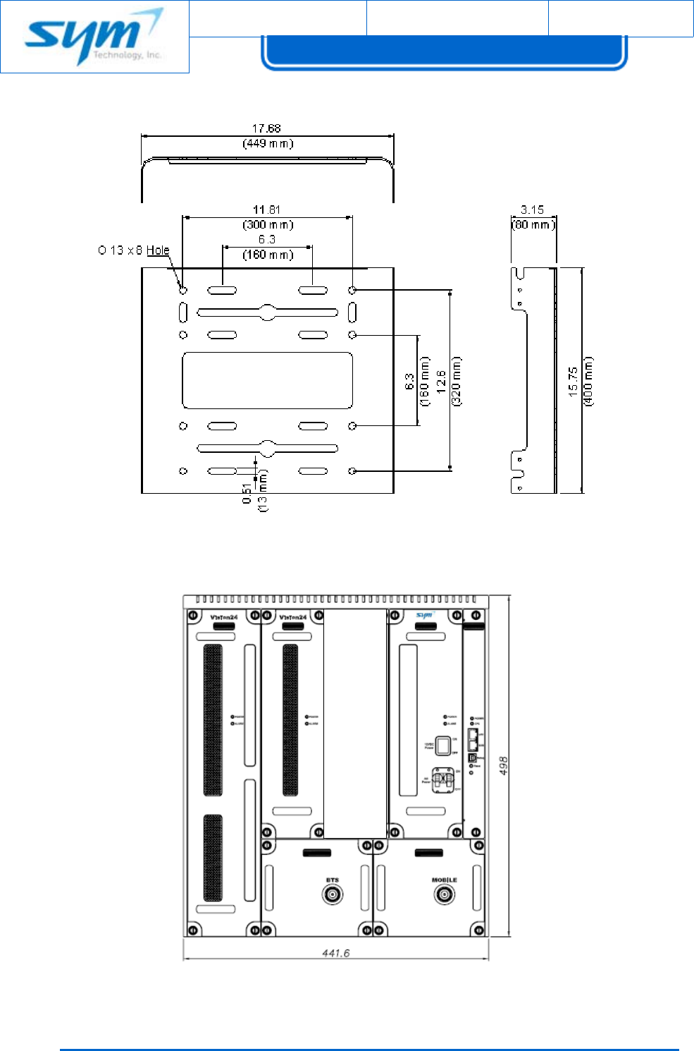
system.Themountingdimensionwithboltsizerequirementsisshownin[Figure2‐1]and[Figure2‐2].
CAUTION:Donotinstalltheservicecarduntiltheenclosureiscompletelyinstalledata
permanentlocation.
WARNINGS:Thumbscrewsshouldbetightenedwithatoolafterbothinitialinstallation
andsubsequentaccesstothepanel.
Document No.:
Date:
August 17, 2012 Version: 2.3
UserManual forVision30
Copyrightⓒ2012SYMTechnology,Inc.Allrightsreserved.
2
0
[Figure2‐1]WallMountBracketDimension
[Figure2‐2]RackMountDimensionDrawings

UsermanualforSoftwareDefinableRepeater
ProprietaryandStrictlyConfidential21
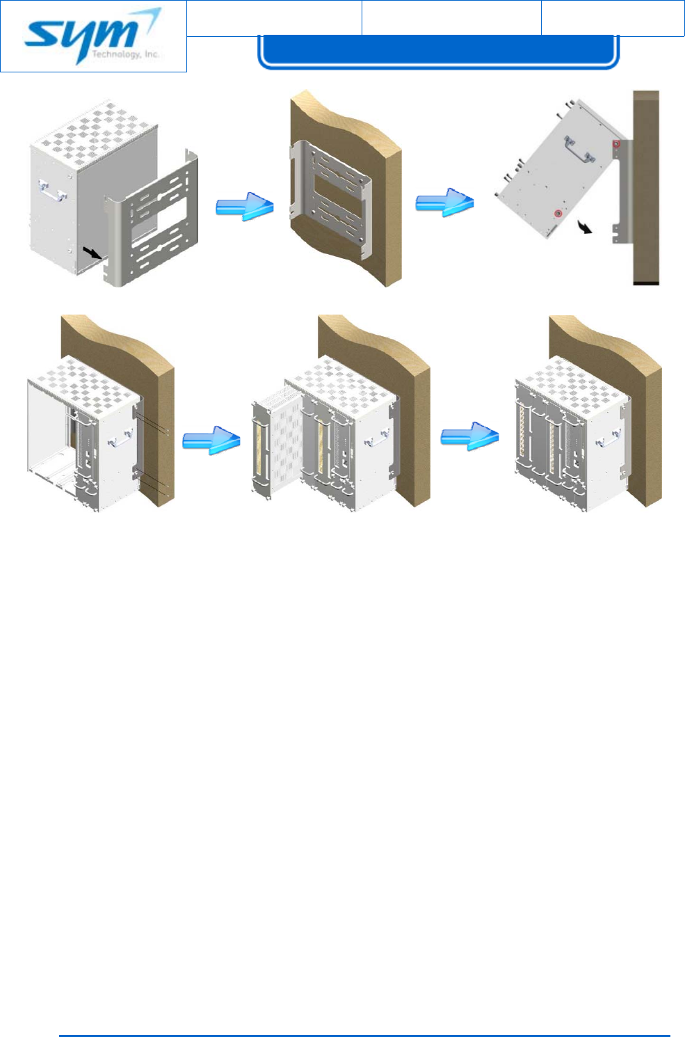
2.3 WallMountingProcedure
Eightmountingholesareprovidedonthewall‐mountingbrackettoattachittothewall.Thewall
bracketmustbesecurelyattachedtosufficientlycarrytheweightoftheVisionenclosure,whichis
boltedtothewallbracketthroughfouralignedmountingholes.
ThefollowingstepsshouldbefollowedwhilemountingtheVisionenclosure:
(1) TaketheVisionenclosureoutofthebox
(2) TaketheallServiceCardsoutoftheenclosure
(3) DetachthemountingbracketfromtheVisionenclosurebyunscrewingthe8screwsonthe
bracket.(4oneachside)
(4) Usingthefouranchorbolts,mountthebracketonthewall
(5) Makesurethebracketissecurelymounted
(6) SlightlytilttheVisionenclosureandmounttheenclosureontothewallasshowninthe
picture.Hooktheupper2guardscrewsfirstandthenslide/pushinthelower2guard
screwsintotheplace.
(7) MakesuretheVisionenclousreissecurelyplacedontothewallbracket
(8) Fastenthe8bracketscrewsbackproperly
(9) SlideeachServiceCardintotheslotandmakesuretheyarepushedinalltheway
Note:InspectServiceCardrear15‐pinD‐Subconnector.Verifyallpinsarestraight,not
recessed,andalignmentshieldisnotbent.
CAUTION:WheninstallingtheServiceCard,donotuseexcessiveforce.Forcingthe
ServiceCardintotheenclosurewillcausethepinsonthe15‐pinD‐Subconnectorofthe
ServiceCardtobecomerecessedorbroken.
(10) AfterslidingServiceCardsintoenclosure,tosecureServiceCards,tightentopandbottom
fourcaptivescrews.
(11) Inspecteverythingissecure
(12) Refertochapter3.2forinitialturn‐on,checkout,andpowersettingprocedures.
Document No.:
Date:
August 17, 2012 Version: 2.3
UserManual forVision30
Copyrightⓒ2012SYMTechnology,Inc.Allrightsreserved.
2
2
[Figure2‐3]Wallmountinginstallation
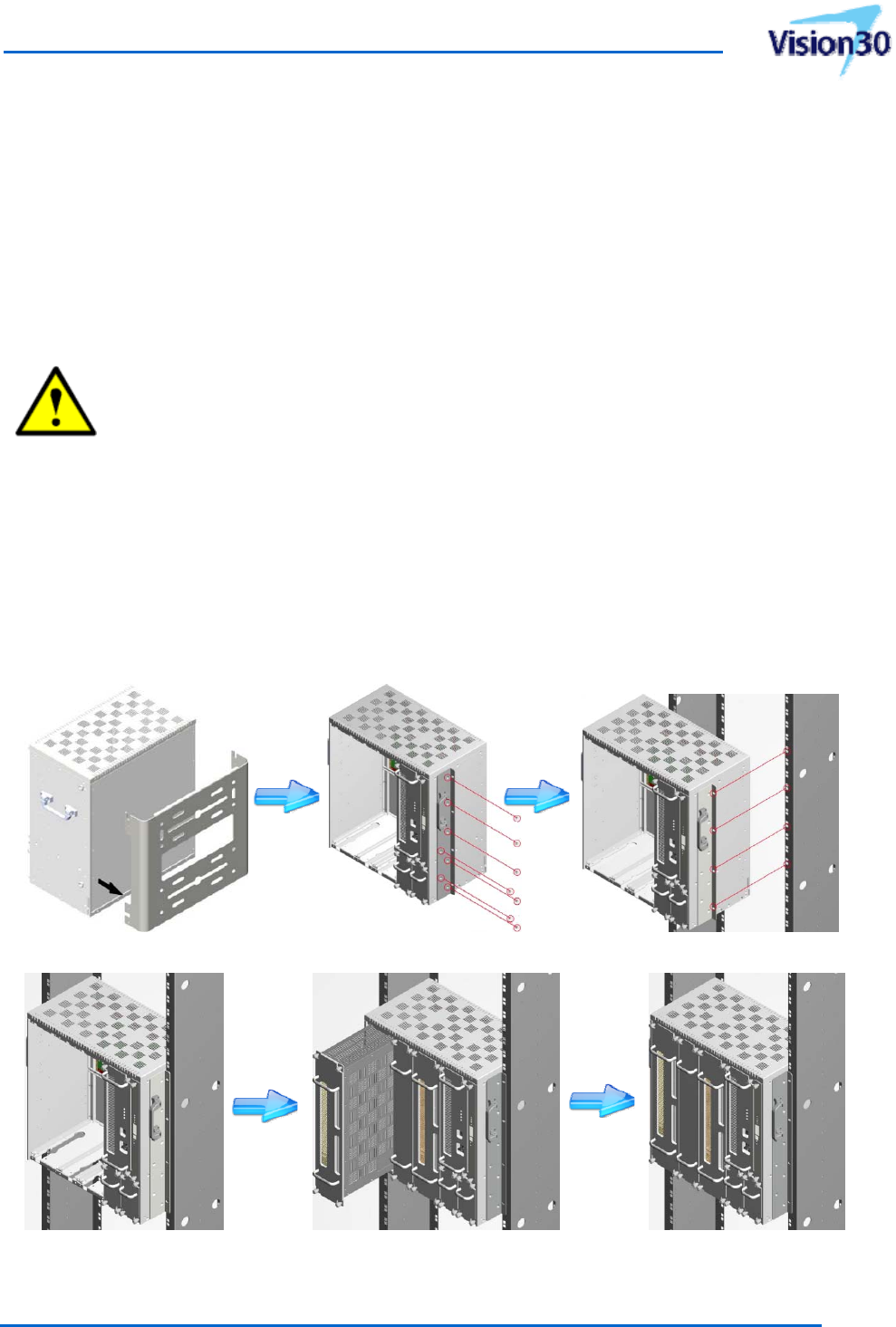
2.4 RackMountingProcedure
Eightmountingholesareprovidedontherack‐mountingbrackettoattachittothe19”rack.Therack
bracketmustbesecurelyattachedtosufficientlycarrytheweightoftheVisionenclosure,whichis
boltedtotherackbracketthrougheightalignedmountingholes.
ThefollowingstepsshouldbefollowedwhilemountingtheVisionenclosure:
(1) TaketheVisionenclosureandrackmountbracketsoutofthebox
(2) TaketheallServiceCardsoutoftheenclosure
(3) DetachthewallmountingbracketandhandlesfromtheVisionenclosurebyunscrewingthe
8screwsonthebracket.(4oneachside)
(4) AttachtherackmountingbrackettotheVisionenclosurebyscrewingtheeighteenflathead
screwsonthebracket.(9oneachside)
(8)(9)(10)
(3)(4)(6)
UsermanualforSoftwareDefinableRepeater
ProprietaryandStrictlyConfidential23
(5) IdentifytheexactlocationforVisionenclosureandusethe8mountboltstostabilizethe
Visionencousure.(4oneachside)
(6) Makesurethebracketissecurelymounted
(7) SlideeachServiceCardintotheslotandmakesuretheyarepushedinalltheway.
Note:InspectServiceCardrear15‐pinD‐Subconnector.Verifyallpinsarestraight,not
recessed,andalignmentshieldisnotbent.
CAUTION:WheninstallingtheServiceCard,donotuseexcessiveforce.Forcingthe
ServiceCardintotheenclosurewillcausethepinsonthe15‐pinD‐Subconnectorofthe
ServiceCardtobecomerecessedorbroken.
(8) AfterslidingServiceCardsintoenclosure,tosecureServiceCard,tightentopandbottomfour
captivescrews.
(9) Inspecteverythingissecure
(10) Refertochapter3.2forinitialturn‐on,checkout,andpowersettingprocedures.
[Figure2‐4]Rackmountinginstallation
(3)(4)(5)
(6)(7)(8)

Document No.:
Date:
August 17, 2012 Version: 2.3
UserManual forVision30
Copyrightⓒ2012SYMTechnology,Inc.Allrightsreserved.
2
4
WARNINGS:
A)ElevatedOperatingAmbient‐Ifinstalledinaclosedormulti‐unitrackassembly,the
operatingambienttemperatureoftherackenvironmentmaybegreaterthanroom
ambient.Therefore,considerationshouldbegiventoinstallingtheequipmentinan
environmentcompatiblewiththemaximumambienttemperature(Tma)specifiedbythe
manufacturer.
B)ReducedAirFlow‐Installationoftheequipmentinarackshouldbesuchthatthe
amountofairflowrequiredforsafeoperationoftheequipmentisnotcompromised.
C)MechanicalLoading‐Mountingoftheequipmentintherackshouldbesuchthata
hazardousconditionisnotachievedduetounevenmechanicalloading.
D)CircuitOverloading‐Considerationshouldbegiventotheconnectionofthe
equipmenttothesupplycircuitandtheeffectthatoverloadingofthecircuitsmighthave
onovercurrentprotectionandsupplywiring.Appropriateconsiderationofequipment
nameplateratingsshouldbeusedwhenaddressingthisconcern.
E)ReliableEarthing‐Reliableearthingofrack‐mountedequipmentshouldbemaintained.
Particularattentionshouldbegiventosupplyconnectionsotherthandirectconnections
tothebranchcircuit(e.g.useofpowerstrips)."
UsermanualforSoftwareDefinableRepeater
ProprietaryandStrictlyConfidential25
2.5 ElectricalInstallation
ReadtheWarnings,Cautions,andNotes.
TheVisionisdesignedforinstallationinlocationsthatpermitaccesstothebottomoftheenclosure
forconnectionofACinputpower,+12VDCoutputpower(forexternalwirelessmodem,UWMS‐01)and
RFcables.
WARNINGS:Thisunituseddangerousvoltages.Lossoflife,severepersonalinjuryor
propertydamagecanbetheresultiftheinstructionscontainedinthismanualarenot
followed.Itiscompulsorytogroundtheunitbeforeconnectingpowersupply.A
groundingcable(yellow‐green,10AWG)isprovidedontheenclosuretoconnectthe
earthgroundcable.
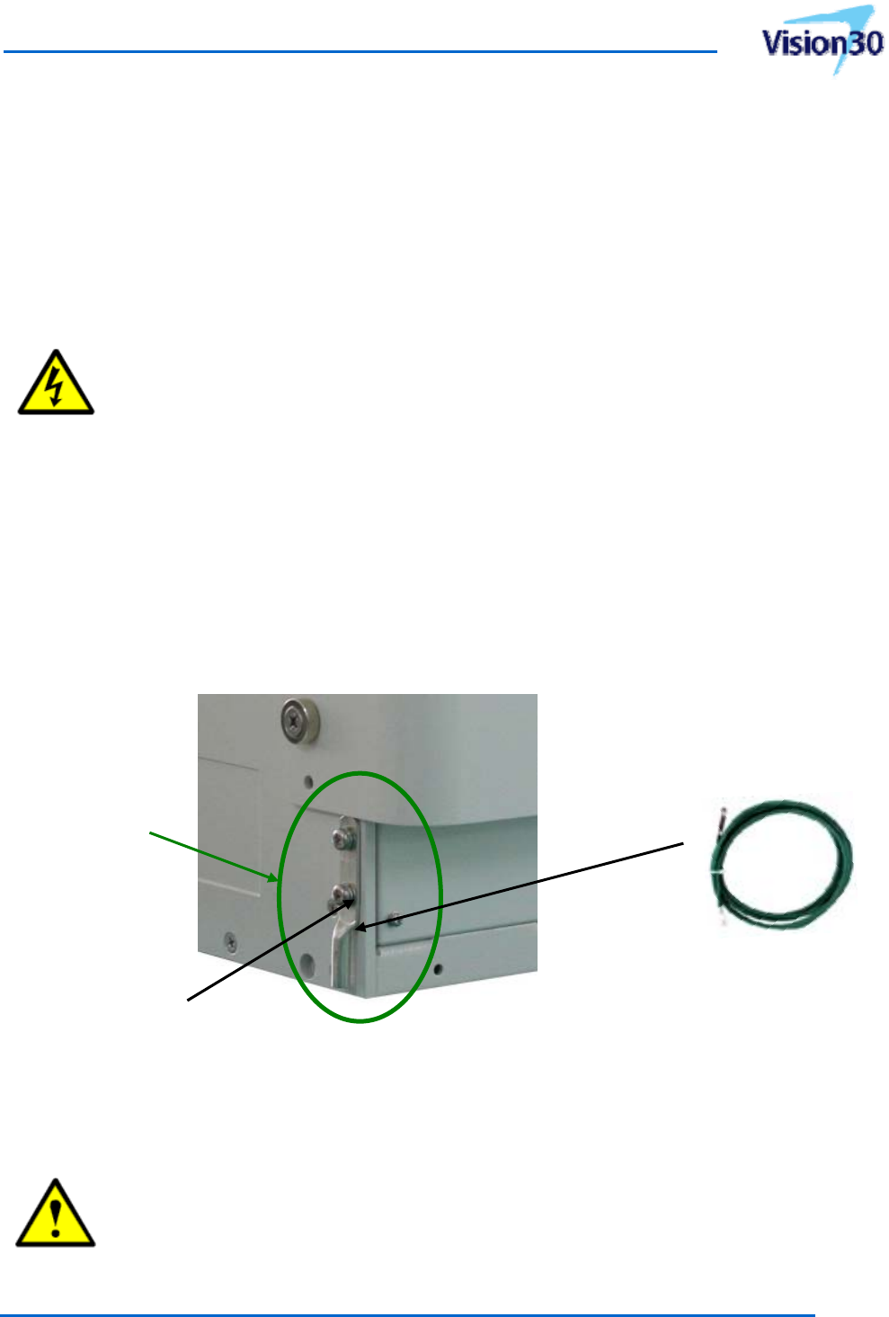
2.5.1 Grounding
Groundingmustbecarriedout.Connectanearth‐bondingcabletothegroundingconnection
providedatthebothsidepanelsoftheVisionenclosure.Donotusethegroundingconnectionto
connectexternaldevices.
[Figure2‐5]Groundingcableconnection
Connectthegroundcable,providedintheVisionenclosurebox,withPH5*8mmpanheadbolts.
CAUTION:ThePEcablesmusthaveaminimumcrosssectionof5.5mm2.Thelocal
groundcablerequiresanadequateearforthePH5GNDbolt.
Positionof
Groundlug
10AWG(Yellow‐Green)
Groundingcable
Connections
Washer
Document No.:
Date:
August 17, 2012 Version: 2.3
UserManual forVision30
Copyrightⓒ2012SYMTechnology,Inc.Allrightsreserved.
2
6
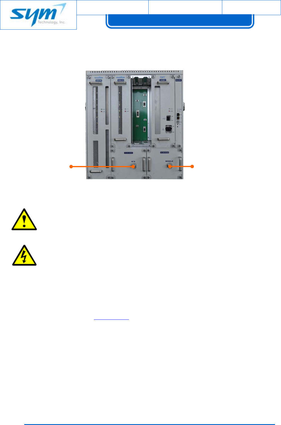
2.5.2 ConnectionoftheAntennaCables
TheconnectionsforantennasarelocatedatthefrontoftheTheVision.
[Figure2‐6]AntennaportontheVision
CAUTION:TightentheNconnectorsonlybyhandortorquewrench.Theuseofpliers
maycausedamagetotheconnectorandimpairtheperformanceoftheVision.
WARNINGS:ExposuretoRadioFrequencyRadiation
TheradiatedoutputpowerofthisdeviceisfarbelowtheFCCradiofrequencyexposure
limits.Nevertheless,thisdeviceshouldbeusedinsuchamannerthatthepotentialfor
humancontactduringnormaloperationisminimized.Inordertoavoidthepossibilityof
exceedingtheFCCradiofrequencyexposurelimits,theminimumseparationdistanceof
9.1inches(23cm)mustbemaintainedbetweenhumanbodyandantennaoftheVision
tosatisfyFCCRFexposurerequirements.FormoreRFexposureinformation,pleasevisit
theFCCwebsiteatwww.FCC.gov
Note:SeparationbetweenDonor(BTS)antennaandService(MOBILE)antennais
necessarytopreventoscillation.Oscillationoccurswhenthesignalenteringthesystem
continuallyre‐enters,duetothelackofseparationbetweentheDonorandService
antennas.Asaresult,thenoiselevelrisesabovethesignallevel.Topreventfeedback,the
DonorandServiceantennasmustbeseparatedbyanappropriatedistancetoprovide
sufficientisolation.Thisdistanceisdependentonthegainoftherepeater.Asufficient
isolationvalueis15dBgreaterthanthemaximumgainoftheVision.
Donor(BTS)
AntennaPort
Service(MOBILE)
AntennaPort
UsermanualforSoftwareDefinableRepeater
ProprietaryandStrictlyConfidential27
2.5.3 ACPowerConnection
Beforeconnectingelectricalpowertotheunit,thesystemmustbegroundedasdescribedinthe
previouschapter(2.5.1).
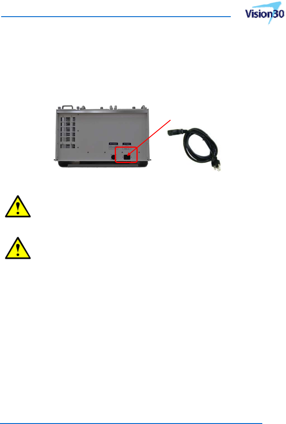
ThemainACpowerinputsocketislocatedonthebottomofVisionenclosure.Mainpowermustbe
connectedatthemainsconnector.ThepowercableisincludedwiththeVisionenclosurepackingbox.
[Figure2‐7]ACpowerinputsocketontheVision
CAUTION:Aminimumcrosssectionof0.83mm2isrequiredforthepowersupply
connection.Eachwiremustobservetheapplicablenationalregulationsregardingloop
impedance,voltagedrop,andmethodsofinstallation.
CAUTION:DonotconnectordisconnectthepowercordattheACmainconnectorwhile
powerison.TurnoffACpowerswitchbeforeconnectingthepowercordattheunit,
thenturnonACswitchagain.
2.5.4 EthernetConnection
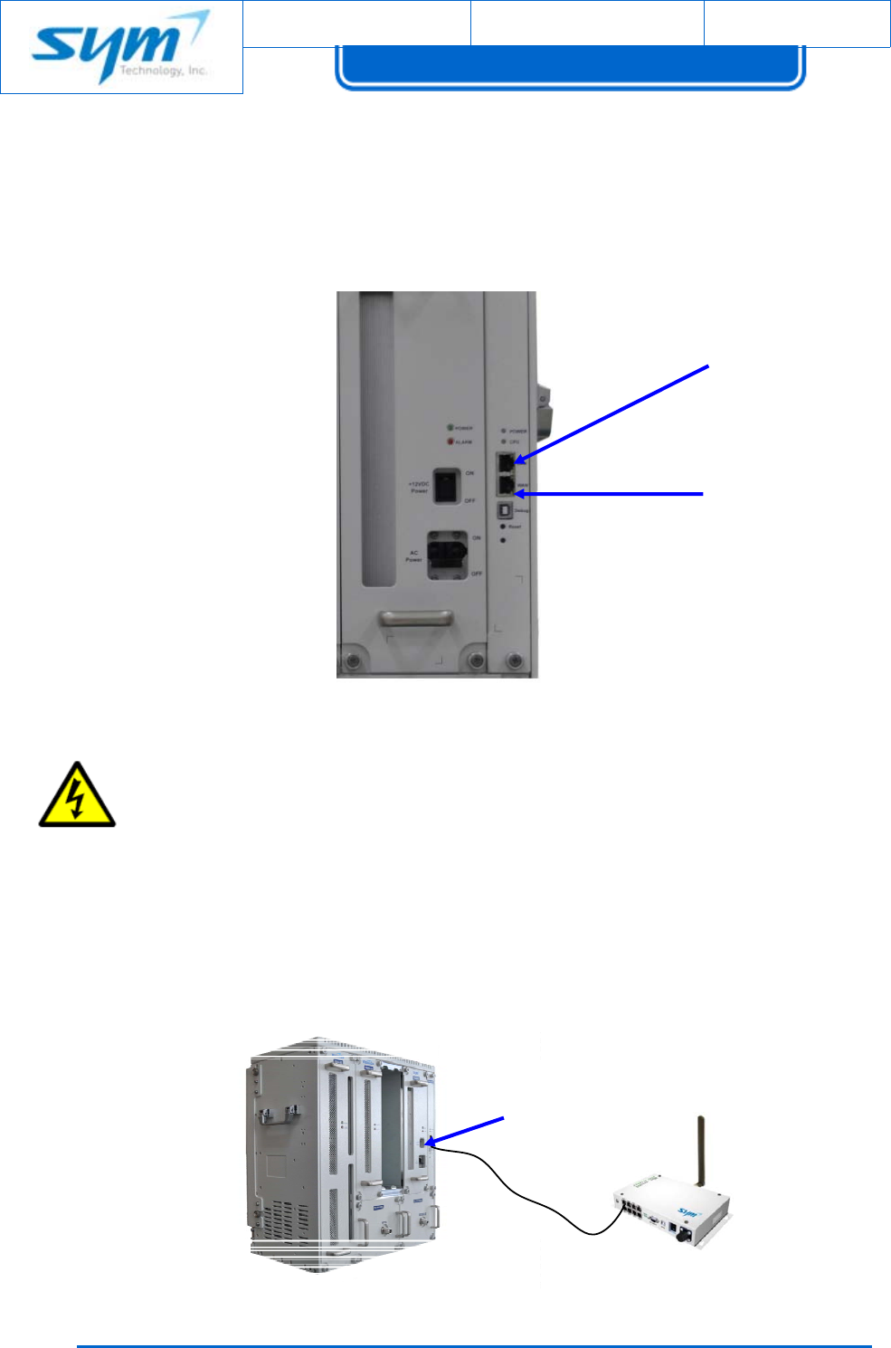
TheEthernetportsarelocatedonfrontoftheVisioncontrollerasshownbelowinError! Reference
source not found.8].
LANEthernetPort(forlaptopconnection)
TheVisioncanbeconfiguredlocallywiththebuilt‐inweb‐basedgraphicaluserinterface.Usinga
providedstandardEthernetcable,connectyourlaptoptothe“LAN”portontheVisioncontroller.The
LANconnectioniseasytosetupandmuchfasterinoperation.TheLANconnectionshouldbeusedfor
initialsetupandwhenevertheoperatorisatsite.
However,beforeyouconnectyourlaptoptotheLANport,verifyyourlaptop’sLocalAreaConnection
ACPowercable
Connections
Document No.:
Date:
August 17, 2012 Version: 2.3
UserManual forVision30
Copyrightⓒ2012SYMTechnology,Inc.Allrightsreserved.
2
8
setting.Formoredetailinformation,pleasereferto“3.3.1networkconnection”.
Aftertheconnectionismadeproperly,theredandgreenLEDsneartheVision’sEthernetconnector
willflash.Thenetworkhardwarewilldeterminethehighestspeedsupportedbybothdevices.With
mostPC’s,theoperatingsystemwillautomaticallyestablishthehardwareandsoftwarenetwork
connection.
[Figure2‐8]EthernetportontheVision
WARNINGS:EthernetInstructions:Thisequipmentisforindooruseandallthe
communicationwiringislimitedtoinsideofthebuilding.
WANEthernetPort(forexternalwirelessmodem,UWMS‐01)
ThisportisusedforconnectionofVisionandexternalwirelessmodemforremoteaccess.Thisport
shouldbeselectedifaCDMA/EVDOmodembox(UWMS‐01)isbeinginstalledalongwiththeVision.
AnIPaddressoftheWANportisconfiguredwith192.168.1.2,staticaddress.
LAN(Local)
Ethernetport
WAN(Remote)
Ethernetport
WAN Ethernetport
UsermanualforSoftwareDefinableRepeater
ProprietaryandStrictlyConfidential29
[Figure2‐9]WANportconnectiontoanUWMS‐01
3. Operation
ThischaptercontainsadescriptionoftheSYMTechnologyVisionindoorSystemcontrolsandindicators,
initialstart‐upandoperatingprocedures,andpowersettingprocedures.
3.1 SystemIndicators
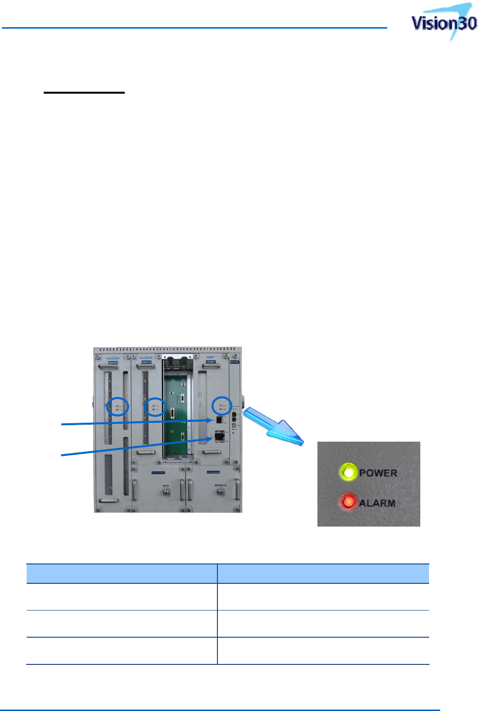
WheninstallationoftheVisionenclosure,ServiceCards,groundingcable,antennaconnectionandAC
powercordiscompleted,turnontheACpowerswitchonthefrontpaneloftherectifier,asshownon
[Figure3‐1]below.
3.1.1 SystemStatusIndicators
Thesystemfrontpanelstatusindicatorsareshownin[Figure3‐1]anddescriptionsarelistedin[Table
3‐1].TherectifierpowersupautomaticallywhensystemACpowerissetto“ON”.
[Figure3‐1]FrontPanel
[Table3‐1]SystemStatusIndicators
LEDIndicatorsDescriptions
800/900MHzServiceCard‐POWER(SolidGreen):Poweron
‐ALARM(SolidRed):Alarm&shutdown
1900MHzServiceCard‐POWER(SolidGreen):Poweron
‐ALARM(SolidRed):Alarm&shutdown
Rectifier ‐POWER(SolidGreen):Poweron
‐ALARM(SolidRed):Alarm(ServiceCardoff)
Note:TheVisionplatformisaplug‐and‐playandthepowerwillbesuppliedtoservicecards,onceAC
ACMainPower
On/OffSwitch
+12VDCOutput
PowerSwitch
Document No.:
Date:
August 17, 2012 Version: 2.3
UserManual forVision30
Copyrightⓒ2012SYMTechnology,Inc.Allrightsreserved.
3
0
powerswitchissetto“ON”.ThereisnoseparateDCswtichforservicecards.
3.1.2 ControllerStatusIndicators
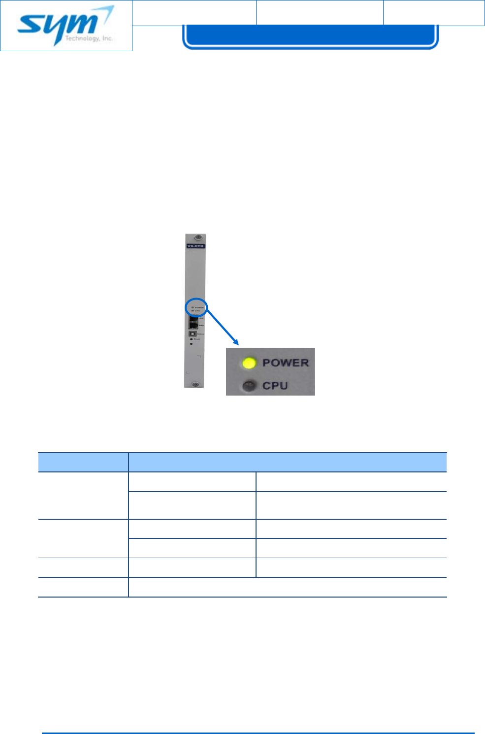
ThelocationandfunctionoftheVisioncontrolsandindicatorsisshownin[Figure3‐2]anddescribed
intheparagraphsthatfollow.ThecontrolsandindicatorsfortheControllerconsistoftheLANport,
WANport,Debugport,Boot/ResetbuttonandstatusindicatorLEDasshownin[Figure3‐2].Thestatus
indicatorLEDhastwo‐colorcapability:Green,Red,andindicatesthestatusofthecontrolleraslisted
anddescribedin[Table3‐2].
[Figure3‐2]ControllerFrontPanelControlsandIndicators
[Table3‐2]ControllerStatusIndicators
ItemDescriptions
LED
Indicators
POWER ‐SolidGreen:Poweron
CPU‐SolidGreenorOff:Abnormalstatus
‐BlinkingGreen:Normalstatus
Ethernet
Interface
LAN‐LaptopConnection
WAN‐ExternalWirelessModemconnect
USBDebug‐CPUDebugport
ResetControllerReboot
UsermanualforSoftwareDefinableRepeater
ProprietaryandStrictlyConfidential31
3.2 Initialstart‐upandpowersettingprocedures
BeforestartupVision,pleasereadchapter3.3ifyouarenotfamiliarwithVisionwebGUI.
Note:TheVisionmustbewarmedupforaminimumof10minutespriortosetting
powerlevels.FailuretoproperlywarmtheVisionmayresultinloweroutputpower,once
theVisionreachesoperatingtemperature.
Toperformtheinitialstart‐up,proceedasfollows:
(1) VerifythatallDonor(BTS)andService(MOBILE)antennaportcablesareproperlyconnected.
(2) ChecktheconnectionstatusbetweenPowercableandGroundcable.
CAUTION:DonotoperatetheVisionwithoutaloadattached.Excessiveinputpower
maydamagetheservicecard.
(3) Checktomakesurethe120VACpowercordisproperlyconnectedtothesystem.
(4) Checktheantennaconnections.
(5) TurnontheACpowerswitchontherectifierfrontpanel.
(6) AccesswebbasedGUIthroughwebbrowserandLANport
(7) Checkthelevelofinputpowerofeachservicecard.Andchangetheantennapositionincase
ofinputoverdrivealarmistriggered.
(8) CheckthesystemalarmonhealthwindowsofWeb‐basedGUI.Ifanysignaldoesn’tcome
fromdonorRSSIinputwhenthesystemisturnedon,InputLowalarmarises.ButtheVisionis
normal.
(9) Refertochapter3.2.1forthepowersettinginstructions.Howtosetupthegainisexplained
inchapter3.3.4.2.
3.2.1 800/900MHzPowerSettingProcedures
(1) Ensurethecompositedownlinkinputpowertothe800/900MHzservicecardis<‐27dBm.
(2) WhenDownlinkinputpowertothe800/900MHzservicecardisataproperlevel,turnonthe
DLHPAusingWebbasedGUI.
(3) AdjusttheDLgainsettingtogeneratemaximumoutputpowerusingWebbasedGUI.Referto
[Table3‐3]below.
(4) DeterminetheoutputpowerlevelattheService(MOBILE)antennaport.
Document No.:
Date:
August 17, 2012 Version: 2.3
UserManual forVision30
Copyrightⓒ2012SYMTechnology,Inc.Allrightsreserved.
3
2
[Table3‐3]DLGainsettingofDownlinkinputpowerincaseofV30‐89(30dBmmodel)
DLInputPowerDLGainDLOutputPower
‐57dBm87dB30dBm
‐47dBm77dB30dBm
‐37dBm67dB30dBm
‐27dBm57dB30dBm
Note:Downlinkanduplinkgainisfactorypresenttominimumgain.Refertosystem
specificationsinchapter5.
CAUTION:IftheoutputpowerlevelatthefrontoftheServiceantennaportexceedsthe
Vision’sspecifiedcapability,reducetheDLgainuntiltheVisionoutputpowerratingis
met.
(5) AdjustDL/ULAGCLimitLevelbelowtheSystemmaximumoutputpower,ifAGCoperation
needed.
(6) AdjusttheULGainlevelequaltoorbelowDLGainlevel.
Note:WhenusingULGainTrackinginWebGUI,ULGainwillbeautomaticallysetbased
onDLGainsetting.
(7) TurnontheULHPAaftersettingULGainorULGainTracking.
(8) Whenallsettingiscompleted,checktomakesuresystemgainandoutputpowerareat
properlevel.
(9) CheckthesystemalarmonhealthwindowsofWeb‐basedGUI
(10) MeasuretheDownlinkouputpowerandspurioustomakesuretheyareproperlyset.
3.2.2 1900MHzPowerSettingProcedures
(1) Ensurethecompositedownlinkinputpowertothe1900MHzservicecardis<‐30dBm.
(2) WhenDownlinkinputpowertothe1900MHzservicecardisataproperlevel,turnontheDL
HPAusingWebbasedGUI.
(3) AdjusttheDLgainsettingtogeneratemaximumoutputpowerusingWebbasedGUI.Referto
[Table3‐3]below.
(4) DeterminetheoutputpowerlevelattheService(MOBILE)antennaport.
UsermanualforSoftwareDefinableRepeater
ProprietaryandStrictlyConfidential33
[Table3‐4]DLGainsettingofDownlinkinputpowerincaseofV30‐19(30dBmmodel)
DLInputPowerDLGainDLOutputPower
‐60dBm90dB30dBm
‐50dBm80dB30dBm
‐40dBm70dB30dBm
‐30dBm60dB30dBm
Note:Downlinkanduplinkgainisfactorypresenttominimumgain.Refertosystem
specificationsinchapter5.
CAUTION:IftheoutputpowerlevelatthefrontoftheServiceantennaportexceedsthe
Vision’sspecifiedcapability,reducetheDLgainuntiltheVisionoutputpowerratingis
met.
(5) AdjustDL/ULAGCLimitLevelbelowtheSystemmaximumoutputpower,ifAGCoperation
needed.
(6) AdjusttheULGainlevelequaltoorbelowDLGainlevel.
Note:WhenusingULGainTrackinginWebGUI,ULGainwillbeautomaticallysetbased
onDLGainsetting.
(7) TurnontheULHPAaftersettingULGainorULGainTracking.
(8) Whenallsettingiscompleted,checktomakesuresystemgainandoutputpowerareatproper
level.
(9) CheckthesystemalarmonhealthwindowsofWeb‐basedGUI
(10) MeasuretheDownlinkouputpowerandspurioustomakesuretheyareproperlyset.
3.3 Web‐basedGUIoperation
Web‐BasedGUIisprovidedforeaseofmanagementandmaintenanceoftheVisionsystem.This
chapterexplainsWeb‐basedGUIoftheVisionplatform.
Note:WebGUIisaccessiblethroughtheInternetExplorer6,7,8,9,GoogleChromeand
FireFox.
Document No.:
Date:
August 17, 2012 Version: 2.3
UserManual forVision30
Copyrightⓒ2012SYMTechnology,Inc.Allrightsreserved.
3
4
3.3.1 NetworkConnection
BeforeusingWebGUI,makesuretheEthernetconnectionbetweenuser’slaptop(orPC)andthe
Controller,LANportoftheVisionisestablished.
3.3.1.1 LocalNetworkConnection
Tonetworkconnection,proceedasfollows:
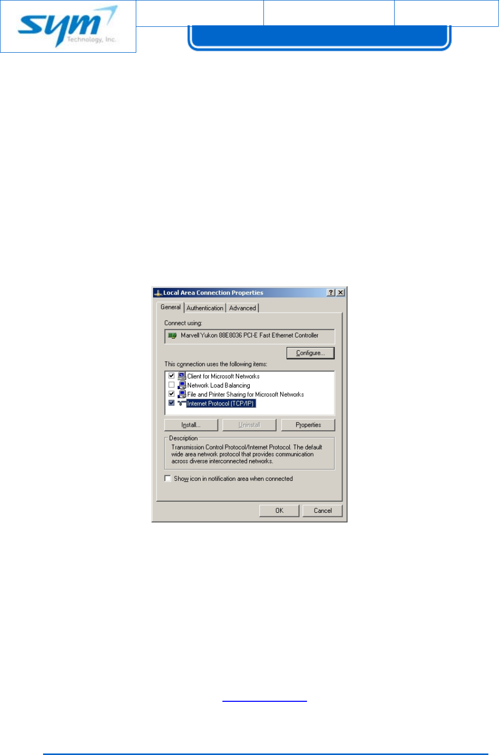
(1) ConnecttheVision,ControllerLANporttoLaptop(orPC)usingEthernetCable(RJ‐45).
(2) SelectTCP/IPinLocalNetworkProperties.
[Figure3‐3]LocalAreaConnectionProperties
(3) IPSetting
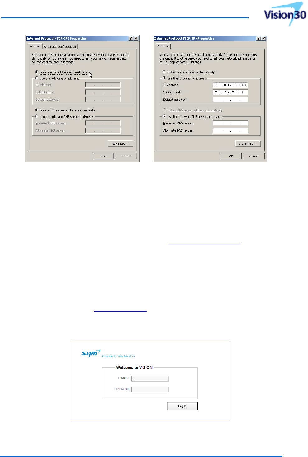
UnderInternetProtocol(TCP/IP)properties,makesuretoselect“ObtainanIPaddress
automatically”. Orwhenselecting“UsethefollowingIPaddress”,besuretouse192.168.2.XXX
(onlyexcept1)andtherecommendedIPaddressis192.168.2.200.
So,assigntheIPaddressesasfollows:
IPaddress:192.168.2.200,Subnetmask:255.255.255.0,Defaultgateway:Leaveitblank
(4) OpenInternetExplorerandtypeinhttp://192.168.2.1
(5) Onceloginscreencomesup,logintotheVision.
UsermanualforSoftwareDefinableRepeater
ProprietaryandStrictlyConfidential35
Automatically(Dynamic)IPassignment Manually(Static)IPassignment
[Figure3‐4]InternetProtocolProperties
3.3.1.2 SprintPrivateNetwork
InordertoconnecttotheSprintPrivateNetwork,theWANportoftheVisionneedstobeconnected
toanexternalmodembox,UWMS‐01asshownin[Figure2‐9].UWMS‐01,universalmodemboxisalso
providedbySYMTechnology,andrefertoUWMSmanualatwww.symtechnology.com
3.3.2 WebbasedGUILogin
Forsecuritypurpose,onlytheauthorizedusercanlogintotheWebGUI.
(1) Openawebbrowser,suchasInternetExplorer,googlechrome,FireFoxandSafari.
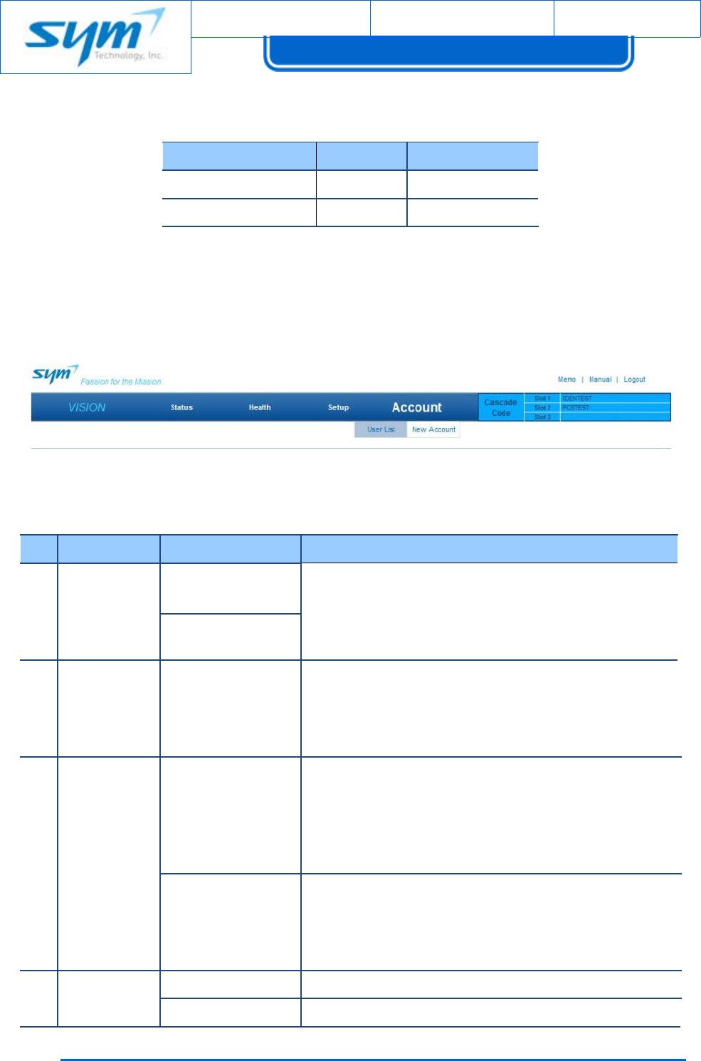
(2) IntheURLfield,enterhttp://192.168.2.1andpressEnter.
The Login Window displays.
[Figure3‐5]WebGUILogin
Document No.:
Date:
August 17, 2012 Version: 2.3
UserManual forVision30
Copyrightⓒ2012SYMTechnology,Inc.Allrightsreserved.
3
6
Authorizeduser(s)mayloginwithdefaultIDandPasswordasshownin[Table3‐9]below.
[Table3‐5]WebGUIAccessID/Password
AccessLevelIDPassword
Administratoradminadmin
Uservisionvision
Onceloggedin,statuspagewillbedisplayed.
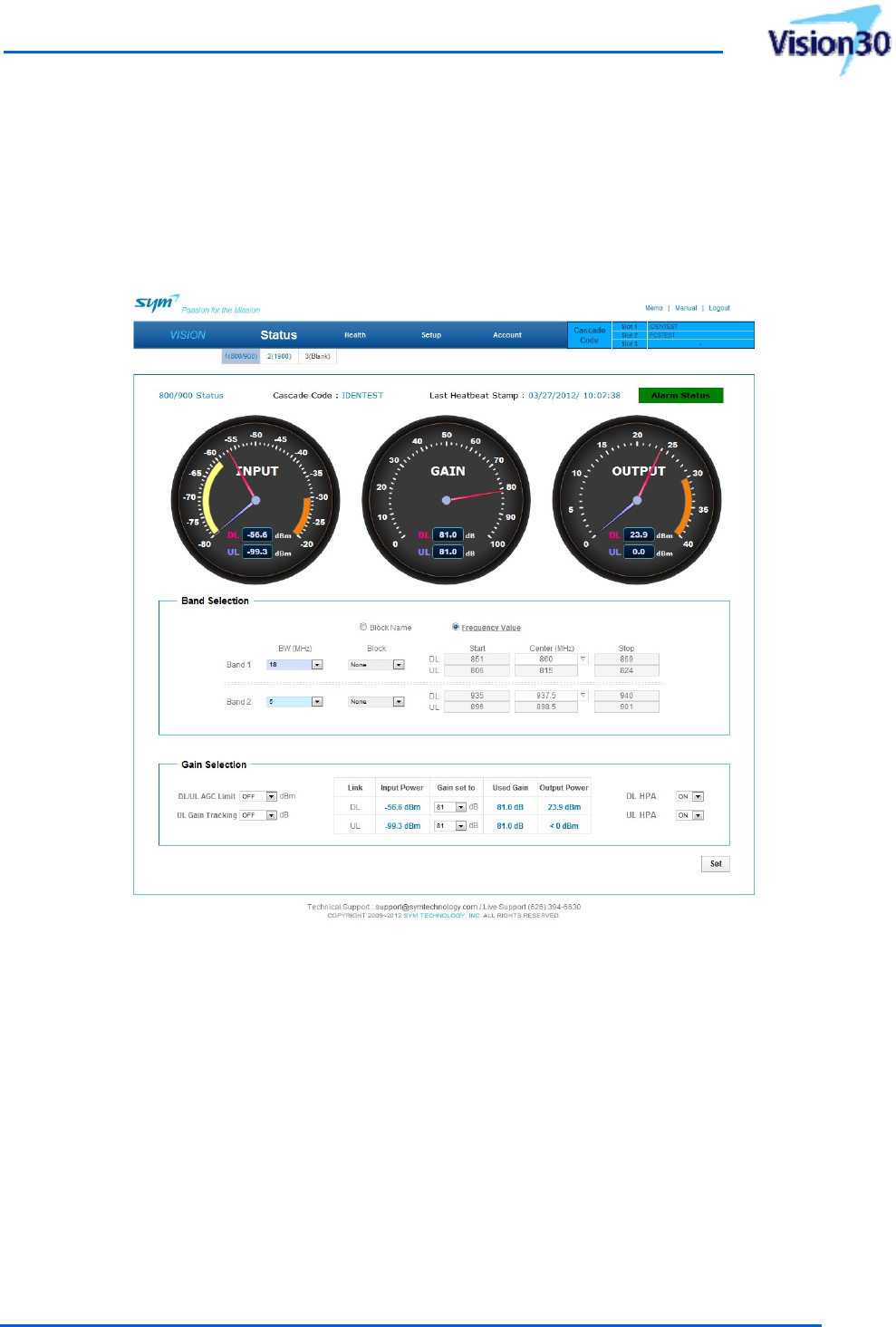
3.3.3 MenuList
TherearefourmainmenusintheWebGUI.
[Figure3‐6]WebGUIMainMenu
[Table3‐6]WebGUIMainMenu
NoMainMenuSubMenuDescription
1Status
800/900
‐Input/Gain/OutputLeveldisplay
‐Subbandselection
‐GainSetting
‐HPAON/OFF
‐Summaryalarmstatus
1900
2Health‐
‐AlarmcheckforeachServicecard
‐SetThresholdlevelforeachServicecard
‐EventLogDisplay
‐TestSNMPAlarm&Clear
‐ProvideInput&OutputGraphforeachServicecard
3Setup
Network
‐SetCascadeandHeartbeatIntervalforeachService
card
‐SetIPAddressofWANPort
‐SetlocationInformaitonofwheretheDeviceisinstalled
‐SetSNMPDestinationIPofSNMPTrap/InformData
‐SetDeviceSystemTime
Install&Update
‐ProvideeachServicecard’sInstallation
‐DeviceFirmwareUpdate
‐EachServicecard’sFactorySet
‐RebootfunctionalityofServiceCardsincluding
Controller
4Account
UserListDisplayofregisteredaccounts
NewAccountRegisternewUser(s)andAdministrator(s)
UsermanualforSoftwareDefinableRepeater
ProprietaryandStrictlyConfidential37
3.3.4 Status
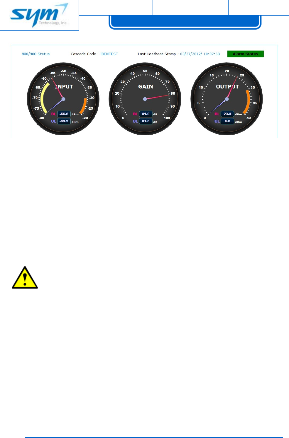
Thestatuspageisdesignedtoprovideacomprehensivestatusofthesystemataglance.Thestaus
updateindisplayedingaugeandisupdatedeveryfiveseconds.
[Figure3‐7]ServiceBandStatus
3.3.4.1 Gauge
ThestatusofeachServiceCardismonitoredanddisplayedinthegaugeandanalarmmessagewillbe
shownwhenalarmistrigged,asshowninError! Reference source not found.8]below.Statusalsohassub
menusfor800/900and1900bandsanddisplaysinputpower,gain,outputpowerofdownlink/uplinkof
eachServiceCard.
Document No.:
Date:
August 17, 2012 Version: 2.3
UserManual forVision30
Copyrightⓒ2012SYMTechnology,Inc.Allrightsreserved.
3
8
[Figure3‐8]StatusPage
3.3.4.2 Band&GainControl
StatusPageprovidesaninterfacewhereusercansetandadjustFrequency,Gain,AGC,Uplink
Tracking,andHPAOn/Offofeachcard.ThisInterfaceisavailableonlywhenthecardispluggedin.When
servicecardisnotpluggedin,submenuwillbeinactive.
InBandSelectionpart,usercansetuptotwobandsfor800/900serviceanduptothreebandsfor
1900service.
CAUTION:Anerrormessagewillbedisplayedwhenthereisanoverlapinfrequencyin
settingbands.Theremustbe0.5MHzfrequencyoffsetinbandsselectionfor800/900and
1900service.Youcannotgoontothenextstepinsettingwhenthereisanerrormessage.
GainSelectionpartallowsusertosetDL/ULAGClimit,ULGainTracking,DLGain,ULGain,DLHPA
andULHPA.InputPower,UsedGainandOutputPowerdisplayedintheGainSelectionareautomatically
updatedaccordingtotheguage.
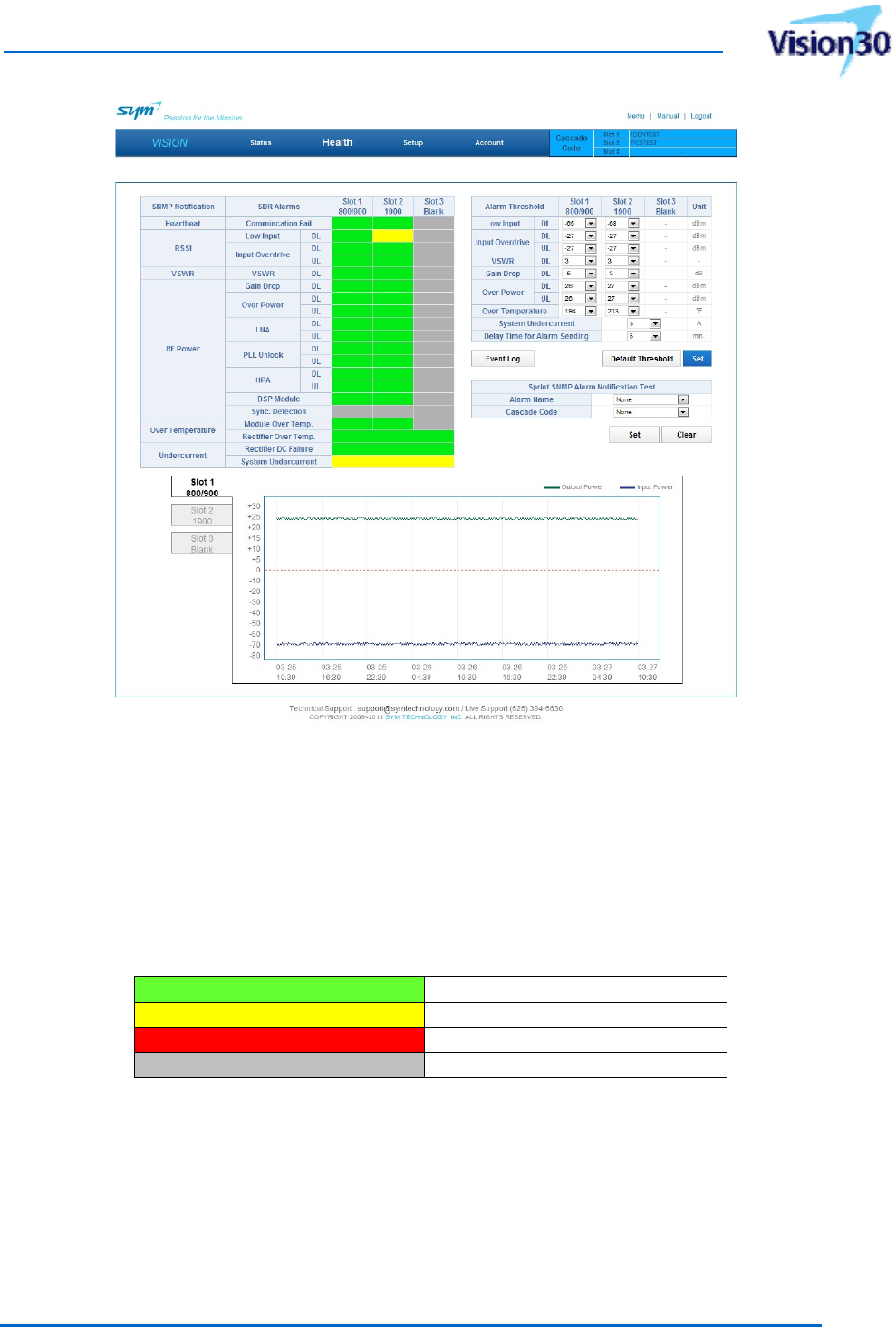
3.3.5 Health
Healthpagedisplayseachservicecard’salarmstaus,alarmthresholdlevelsetting,eventlog,SNMP
testalarmtransmission,downlinkinputpowerandoutputpoweringraph.
UsermanualforSoftwareDefinableRepeater
ProprietaryandStrictlyConfidential39
[Figure3‐9]HealthPage
3.3.5.1 AlarmStatusMonitoringforServiceCard
HealthPagechecksandmonitorsmodule’salarmstatusinreal‐time.Therearefourdifferentcolorsof
displaydependingontheseverityofalarmsasshownbelow.
[Table3‐7]AlarmStatusforHealthPage
GreenNORMAL
YellowMinorAlarm
RedMajorAlarm
GrayServiceCardnotinserted
Note:HealthPageprovideshelpnotesonalarmstatus.Whenplacingyourmouseonthe
alarm,aballonhelpnotewillpopup.
3.3.5.2 SettingAlarmThreshold
HealthPageprovidesanInterfacewhereusercansetAlarmThresholds.UsercandefineAlarm
thresholdsorusethedefaultthresholdsprovidedbysystem.
Document No.:
Date:
August 17, 2012 Version: 2.3
UserManual forVision30
Copyrightⓒ2012SYMTechnology,Inc.Allrightsreserved.
40
3.3.5.3 EventLog
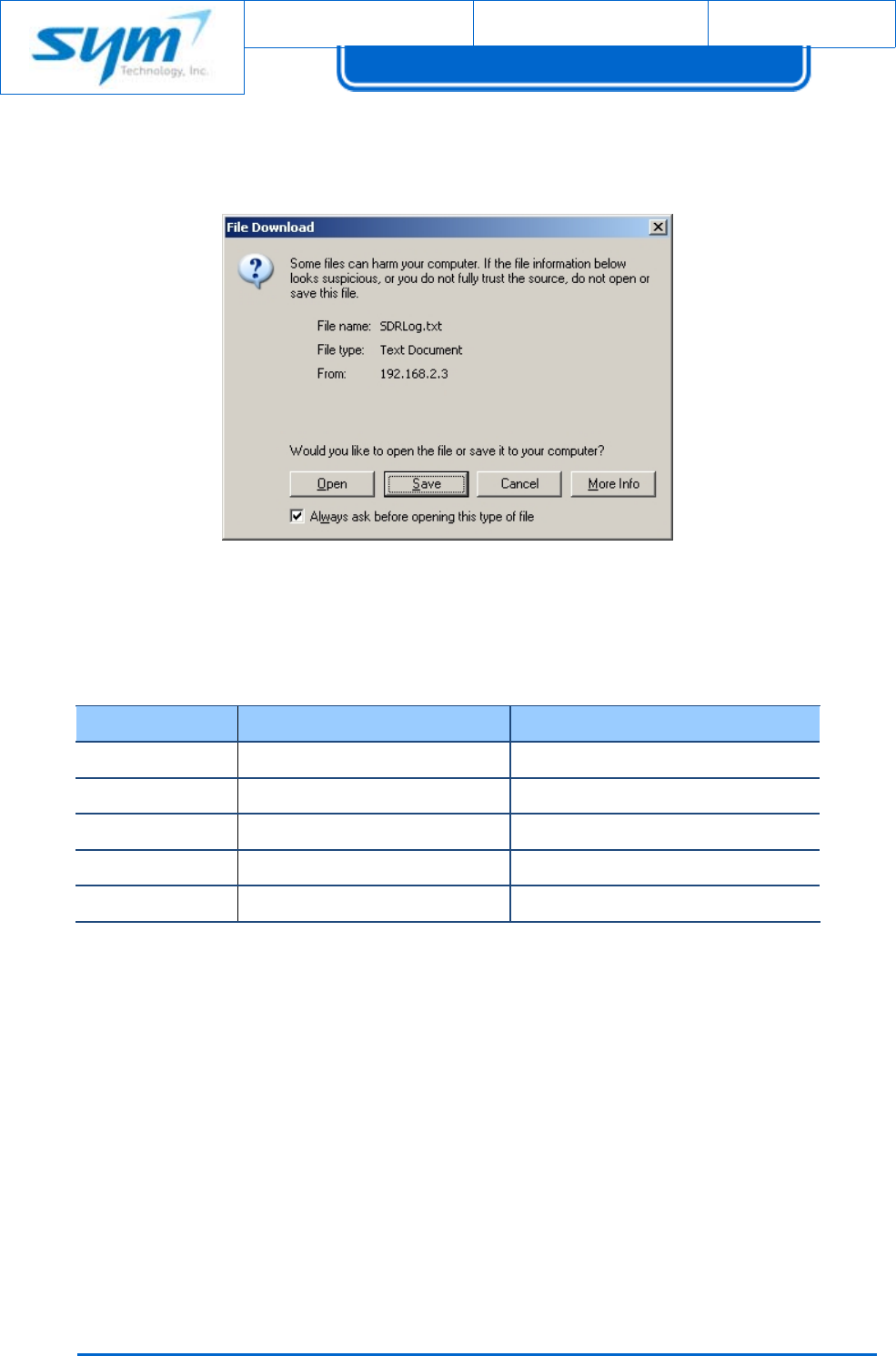
HealthPageallowsusertosaveandvieweventlog.Clickonthe“EventLog"toseethePop‐up
Messageasshownbelow.UsercaneithersaveoropentheEventLog.
[Figure3‐10]EventLogPop‐up
ThefollowingarethedescriptionsofEventLog.
[Table3‐8]EventLogDescription
MessageParameterDescription
Date&TimeMM/DD/YYhh:mm‐
CascadeCodeUpperlettersSiteIDofServiceCard
LevelSystem,800/900,1900FieldReplaceableUnits
StatusEvent,Trap,Alarm,ClearStatusInformation
DescriptionEventNameAlarmInformation
3.3.5.4 SNMPTestAlarm
HealthPageprovidesaninterfaceforusertochecktheconnectionstatusofthedevicebysending
testalarm.TestalarmtransmitsSNMPTraptotheIPaddresssetinSetupPage‐>Network’sSNMP
ManagerIP.
3.3.5.5 Input&OutputGraph
HealthPagedisplayseachservicecard’sInputPowerandOutputPowerinGraph.Eachdotis
displayedeveryfiveminutesandsystemkeepsanddispalyslast48hoursofdata.Clickon800/900and
1900tabstomoveovertoitsserviceband’sgraph.

UsermanualforSoftwareDefinableRepeater
ProprietaryandStrictlyConfidential41
3.3.6 Setup
3.3.6.1 Network
NetworkPageallowsusertosetDevice’sNetworkenvironment,systeminstalledlocationandtime.
[Figure3‐11]NetworkPage
3.3.6.1.1 Cascade&Heartbeat
Upto3cascadecodescanbeassignedbasedoninsertedservicecards.Eachcascadecodeshould
beuniguegivenbySprint.Duplicatedcascadecodewon’tbeassignedonthewebGUI.Usercanputin
upto23capitallettersasCascadeCodeandsettheHeartbeatintervalfrom1to120minutes.Heartbeat
canbeoffaswell.Heartbeattimesetat20minutesbydefault.
Ifheartbeatintervalissetto1to5minutesforconnectingUWMS‐01,thisheartbeatintervalwillbe
automaticallysetto20minutesafter30minuteslater.
3.3.6.1.2 Location
LatitudeandLongitude:TypeintheGPSinformationofthesitewheretheVisionisinstalled.
Withoutthelocationinformation,heartbeatswillnotbegenerated.ThelatitudeformatisN+
ddd.dddddd,e.g.,N+39.006957.ThelongitudeformatisW‐ddd.dddddd,e.g.,W‐94.532306.

Document No.:
Date:
August 17, 2012 Version: 2.3
UserManual forVision30
Copyrightⓒ2012SYMTechnology,Inc.Allrightsreserved.
42
3.3.6.1.3 EthernetConfiguration
ThisEthernetsetupisforWANportincaseofexternalwirelessmodem,UWMS‐01orT1/DSL
connectioniftheVisionsendsoutalarmtothepublicnetwork).ThisportcanworkatDHCPclient
(ObtainIPaddressautomatically)orStaticIPaddressmode.Bydefault,StaticIPaddressisassignedto
beconnectedtoanUWMS‐01asfollows:
IPaddress:192.168.1.2,Subnetmask:255.255.255.0,Defaultgateway:192.168.1.100.
3.3.6.1.4 SNMPDestinationIP
ThisisthetargetIPaddressestowhichtheVision’sdataisdirected.Use10.22.25.15(defaultvalue)
(or192.168.1.100whenUWMS‐01isconnected)astheSNMPDestinationIP.
WhentheVisionisconnectedtothepublicnetwork,theSNMPDestinationIPaddressshouldbe
changedtoproperone.
3.3.6.1.5 Date&TimeSetting
AssigncorrectDateandTimeinformation.Eventlogwillrecodalleventbasedonthisdateandtime.
3.3.6.1.6 Wi‐FiSetting
TheVisionincludes802.11b/g/nwirelessUSBmodule,whichoperatesinthe2.4GHzfrequency
spectrum.ThismeanstheVision24/30canworkasWi‐FiAP.Usercanconnectalaptoporsmartphone
wirelesslyviaWi‐Fi.ThiswillletusernottoclimbupaladdertoconnectalaptoptotheVisonwhenitis
locatedonthehighlevel.
WARNINGS:ExposuretoRadioFrequencyRadiation
Theradiatedoutputpowerofthisdevicerequirestheminimumseparation
distanceof9.1inches(23cm)mustbemaintainedbetweenhumanbodyand
antennaoftheVisiontosatisfyFCCRFexposurerequirements.FormoreRF
exposureinformation,pleasevisittheFCCwebsiteatwww.FCC.gov
Bydefault,Wi‐Fiisenabled.Vision’sdefaultWi‐FiSSIDisVision‐repeaterandpasswordisvision‐sym
Note:ThisWi‐FiAPdoesn’thaveactualinternetconnection.Itwilhelponlywireless
connectiontotheVisiontoaccessitswebGUIwirelessly.
ToaccessVisionWebGUIthroughWi‐Fi,usebelowURLafterconnectingVison‐repeater.
(1) OpenawebbrowserofLaptoporSmartPhone,suchasInternetExplorer,google
chrome,firefox,Safari.
UsermanualforSoftwareDefinableRepeater
ProprietaryandStrictlyConfidential43
(2) IntheURLfield,enterhttp://192.168.3.254andpressLoginButton.
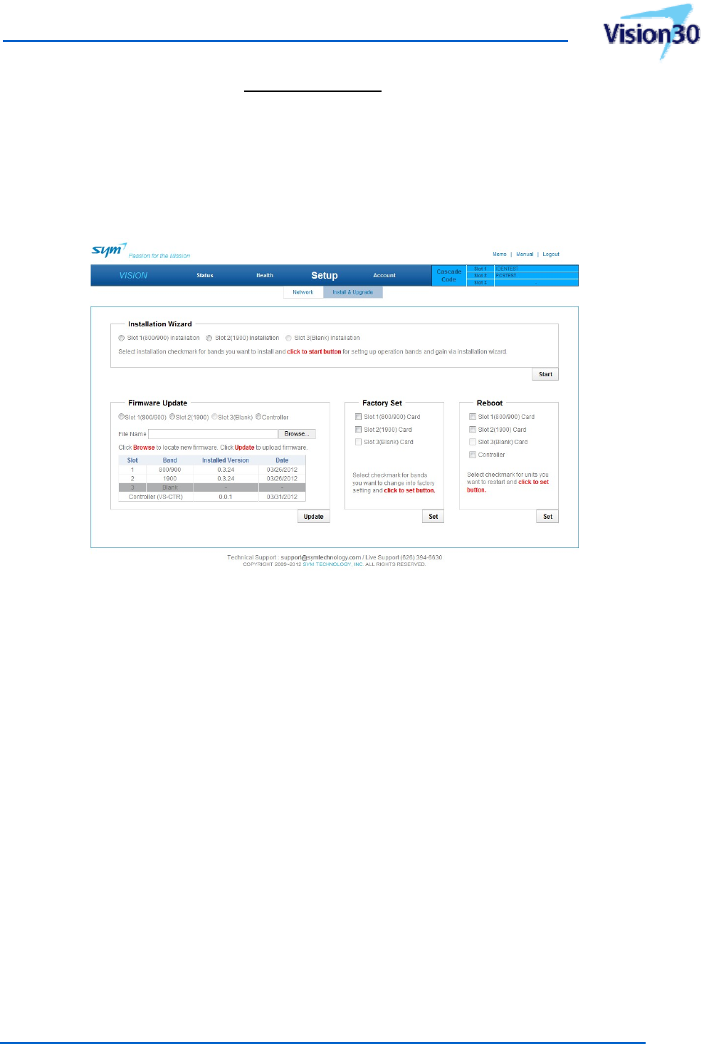
3.3.6.2 Install&Update
Install&UpgradepageisprovidedforeaseofSystem’sinitialsep‐up.ThispageprovidesInstallation
Wizard,Firmwareupdates,FactorySetandReboot.
[Figure3‐12]Install&Upgradepage
3.3.6.2.1 InstallationWizard
InstallationWizardprovidesaninterfaceforaneasysetup.Selecttheservicebandtobeinstalled
andthenclickon“Start”buttontoseethenextstepsshownbelow.(Thischapterwillshow800/900
servicecardinstllationasanexample).
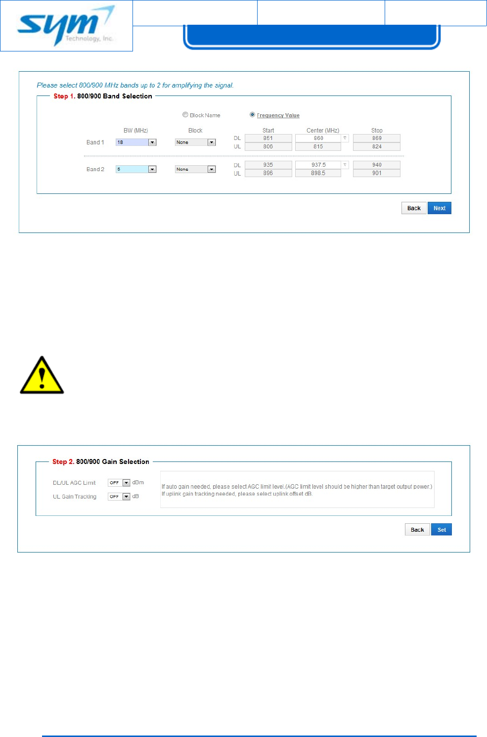
Step1.BandSelection
Document No.:
Date:
August 17, 2012 Version: 2.3
UserManual forVision30
Copyrightⓒ2012SYMTechnology,Inc.Allrightsreserved.
44
[Figure3‐13]InstallationWizardviaStep1
InBandSelection,usersetsFrequencytobeservicedandhasBlockNameandFrequencyValue.Block
NamehasBandwidthandBlock,andFrequencyValuehasBandwidthandcenterfrequencytobe
selected.
CAUTION:Anerrormessagewillbedisplayedwhenthereisanoverlapinfrequencyin
settingbands.Theremustbe0.5MHzfrequencyoffsetinbandsselectionfor800/900and
1900service.Youcannotgoontothenextstepinsettingwhenthereisanerrormessage.
Step2.GainSelection
[Figure3‐14]InstallationWizardviaStep2
GainSelectionPageallowsusertosetthegainofservicecardbasedonuserdefinedoutput.
Ifautogain(AGC)needed,pleaseselectAGClimitlevel.AGClimitlevelshouldbehigherthantarget
outputpower.Ifuplinkgaintrackingneeded,pleaseselectuplinkoffsetdB.Uplinkgaintracking
maintainsthedifferencetheoffsetdBfromthedownlinkgain.
UsermanualforSoftwareDefinableRepeater
ProprietaryandStrictlyConfidential45
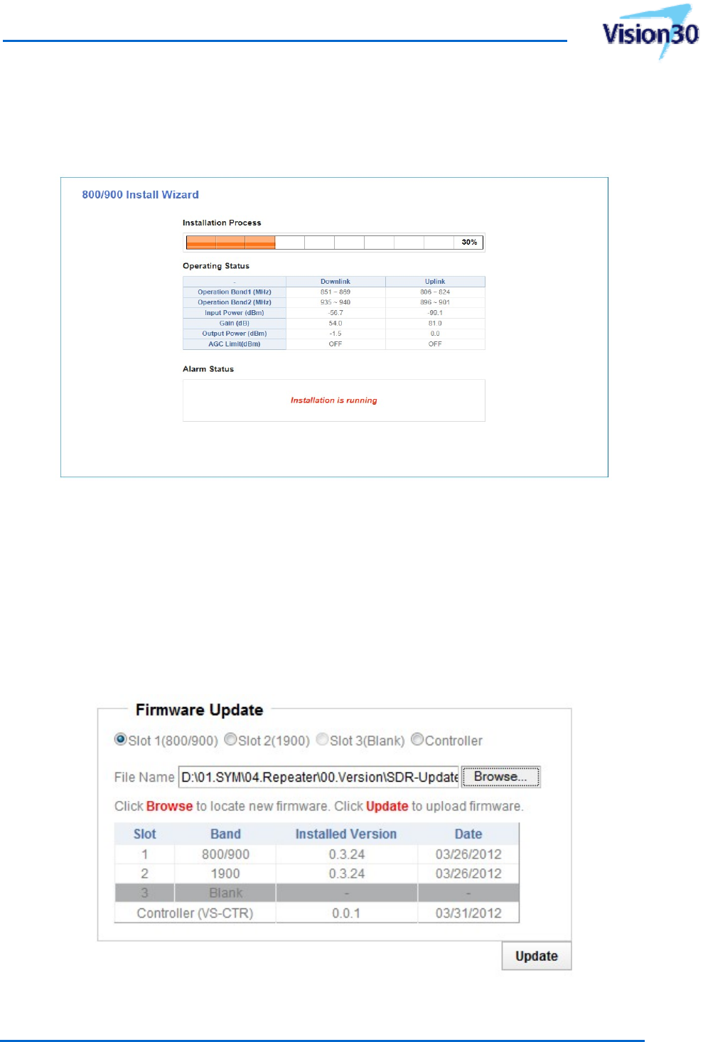
Step3.InstallationProcess
InstallationProcessillustratesthepocessofinstallation.Intheeventofanerror,thealarmwillbe
displayedinalarmstatusandinstallationwillfail.Insuchcase,allsetvalueswillberesettotheprevious
values.
[Figure3‐15]InstallationWizardProcessviaStep3
3.3.6.2.2 FirmwareUpdate
PerformFirmwareUpdateoftheVision.
(1) ChecktheslotorcontrollertobeupdatedontheFirmwareUpdateblock.
(2) Click“Browse”button.
(3) SelectthefileneededtoupdatefromtheDialogue.
WhencompletingFirmwareUpdate,theWebGUIwillcloseautomaticallyandthesystemwillreboot.
[Figure3‐16]FirmwareUpdate

Document No.:
Date:
August 17, 2012 Version: 2.3
UserManual forVision30
Copyrightⓒ2012SYMTechnology,Inc.Allrightsreserved.
46
3.3.6.2.3 FactorySet
ThisfeatureresetsallparameterstoFactorydefaultsetting.Thecheckboxforfeatureisonlyavailable
toinstalledservicecard(s).
[Figure3‐17]FactorySet
3.3.6.2.4 Reboot
Thisfeaturerebootsselectedservicecard(s)andthecheckboxforfeatureisonlyavailabletoinstalled
servicecard(s).Whenselectingthisfeature,theWebGUIwillcloseautomaticallyandthesystemwill
reboot.
3.3.7 Account
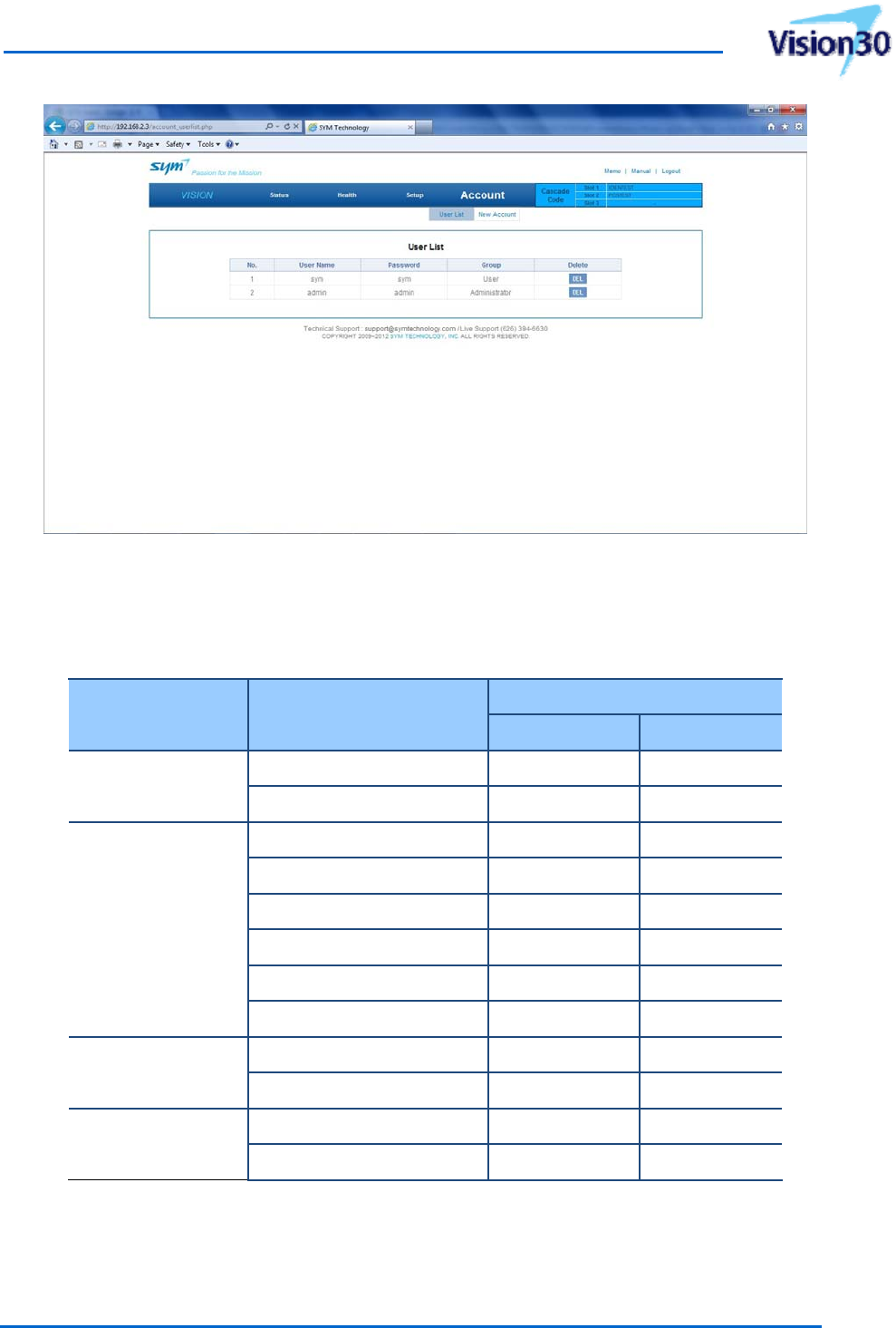
3.3.7.1 UserList
ThisfeaturedisplaysauthorizedoperatorsforWebGUIaccess.
UsermanualforSoftwareDefinableRepeater
ProprietaryandStrictlyConfidential47
[Figure3‐18]UserListPage
UserGrouphasAdministratorandUserandtheiraccessauthorityisshownbelow.
[Table3‐9]UserGroupAccessAuthority
WebGUIpageItem
UserGroup
AdministratorUser
Status 800/900 O O
1900 O O
Health
SDR Alarm (SNMP) O O
Alarm Threshold O △
Default Threshold O △
Event Log O O
Test Alarm (SNMP) O △
Power History O O
Setup Network O △
Install & Upgrade O △
Account User List O X
New Account O X
*△: View only, X: Access not allowed
Administratoraccountislimitedto5only.Useraccount(s)canbeaddedordeletedby
Administrator(s).
Document No.:
Date:
August 17, 2012 Version: 2.3
UserManual forVision30
Copyrightⓒ2012SYMTechnology,Inc.Allrightsreserved.
48
3.3.7.2 NewAccount
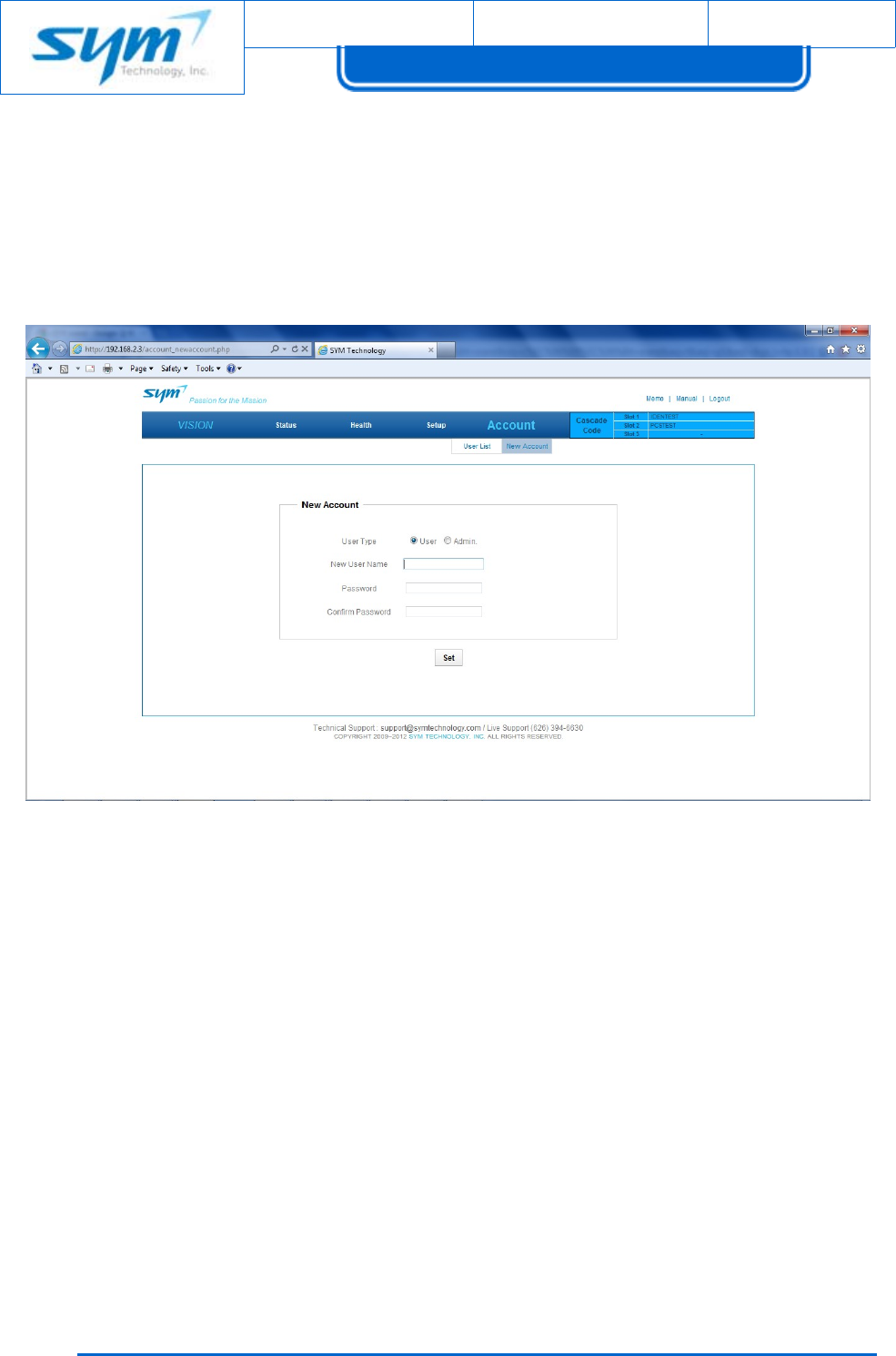
NewAccountPageallowsoperatortoregisterUserandAdministratorintheGroup.Useraccountand
passswordupto35alpha‐numericcharacters,upperandlowercaseareallowed.
[Figure3‐19]NewAccountPage
3.3.8 MemoPad
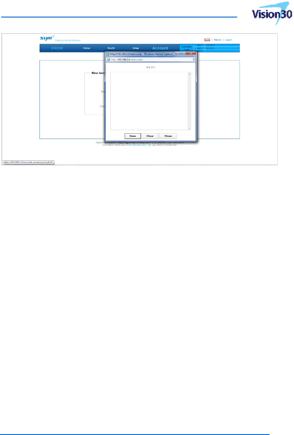
TheMemopadisavailableontheupperrighthadcornerofWebGUIforoperatorand/orSystem
Managertotakenotes.ClickontheMemoandaMemobrowserwillbedisplayedasshownbelow.
UsermanualforSoftwareDefinableRepeater
ProprietaryandStrictlyConfidential49
[Figure3‐20]MemoPage
Makesuretoclickon"Save",otherwisenoteswillbelost.
3.3.9 OtherMiscellaneousFeatures
System’smanualisavailablefordownloadontheupperrightcornerofWebGUI.LogoutMenuallows
operatortologoutfromtheWebGUI.WhenclickingLogout,aLoginwindowwillbedisplayed.
Document No.:
Date:
August 17, 2012 Version: 2.3
UserManual forVision30
Copyrightⓒ2012SYMTechnology,Inc.Allrightsreserved.
5
0
4. Maintenance
ThissectioncontainsperiodicmaintenanceandperformancetestproceduresfortheVision.
Note:Checkyourorderandequipmentwarrantybeforeattemptingtoserviceorrepair
theVision.Donotbreakthesealsonequipmentunderwarrantyorthewarrantywillbe
nullandvoid.Donotreturnequipmentforwarrantyorrepairserviceuntilproper
shippinginstructionsarereceivedfromthefactory.
Intheeventofamalfunction,theusershouldcheckthestatusoftheantennas,feedercables,
connectors,andmainspowerbeforereplacinganycompoents.
4.1 Troubleshooting
TheHealthwindowintheGUIindicateswhenandhowoftenfaultshaveoccurred.SeeError!
Reference source not found.]formoreinformation.ThePOWERandALARMLEDslocatedontheeach
servicecard,controllerandtherectifierfrontpaneldisplaythecurrentoperatingconditionoftheVision
(refertochapter3.1).IftheLEDsindicateaproblem,suggestionsarelistedin[Table4‐1]and[Table4‐2].
CAUTION:Themanualcontainsinformationandproceduresforinstallation,operation,
andmaintenanceoftheVision.Itishighlyrecommendedtoreadthemanualthoroughly
beforebeginningtroubleshooting.SYMTechnologyrecommendsthatmaintenancebe
performedbyaqualifiedindividualorfirmpriortoequipmentinstallationorreplacement.
[Table4‐1]LEDIndicatorsTroubleshootingguide
ProblemSuggestedAction
NorectifierLEDsarelit
1.Checktoseewhetherproperpowerisbeingsupplied
throughACpowercord.
2.SetrectifierfrontpanelACPowerswitchtoONposition.
3.Defectiverectifier–replace.
NoservicecardLEDsarelit
1.SetrectifierfrontpanelACPowerswitchtoON(I)position.
2.ChecktoseeifServiceCardisinsertedproperly.
3.Defectivecontroller–replace.
NocontrollerLEDsarelit
1.SetrectifierfrontpanelACPowerswitchtoON(I)position.
2.Push‘Reset’buttononcontrollerfront
3.Defectivecontroller–replace.
NotcommunicationEthernet1.Verify suppliedEthernetcable
2.SetTCP/IPpropertiesofPC:“ObtainanIPaddress

UsermanualforSoftwareDefinableRepeater
ProprietaryandStrictlyConfidential51
automatically”
3.ConfirmifIPaddressis192.168.2.200incaseof“Usethe
followingIPaddress”ofTCP/IPproperties
4.MakesureifalaptopisconnectedtoaLANport
5.Push‘Reset’buttononcontrollerfrontpanelandthen
rebootlaptopPC.
6.Defectivecontroller–replace
RectifieralarmLEDredonat
rectifierfrontpanel.
1.OutofrangeofACpowervoltage(105to125VAC)orDC
powervoltage
2.SetrectifierfrontpanelACPowerswitchtoON(I)position
3.Defectiverectifier–replace.
1900LEDredonatservice
cardfrontpanel
1.Analarmhasbeendetectedin1900servicecard.Check
healthwindowintheWebGUI.
2.Followtroubleshootingprocedureof[Table4‐2].
800/900LEDredonatservice
cardfrontpanel
1.Analarmhasbeendetectedin800/900servicecard.Check
healthwindowintheWebGUI.
2.Followtroubleshootingprocedureof[Table4‐2].
CPULEDsolidgreenonorOff
atcontrollerfrontpanel
1.ControllerisinSleepMode.
2.Push‘Reset’buttononcontrollerfront
3.Defectivecontroller–replace
[Table4‐2]SystemAlarmontheWebGUITroubleshootingguide
ProblemSuggestedAction
CommunicationFailredalarm
1.ChecktoseeiftheServiceCardisinsertedproperly.
2.SelectRebootinWebGUIsetup>install&upgradewindow
andclickonApply.
3.Defectiveservicecard–replace.
LowInputyellowalarm
1.CheckdownlinkinputpowerlevelonBTS(donor)port.
SystemwillstilloperatenormallyeventhereislowInput
power.
2.Trytiltingthedonorantenna.
InputOverdriveredalarm
1.Checkdownlinkinputpowerlevel onBTS(donor)port.
2.Verifyhighlimitthresholdlevelofinputoverdrive
3.Trytiltingthedonorantennatoadjusttotheproperinput
powerlevel.
4.OscillationduetolackofisolationbetweentheAntennas.Try
relocatingortiltingtheantennas.
VSWRredalarm
1.CheckthecableconnectedtoMOBILE(service)port.
2.ReconnectRFCabletoMOBILEport
3.VerifyhighlimitthresholdlevelofVSWR.
4.TurnontheDLHPA.
5.Defectiveservicecard–replace.
GainDropyellowalarm
1.Checkdownlinkinputpowerandoutputpowerlevel.
2.VerifyGainDropthresholdlevelandthendowngradelow
powerthresholdlevel.
3.Defectiveservicecard–replace.

Document No.:
Date:
August 17, 2012 Version: 2.3
UserManual forVision30
Copyrightⓒ2012SYMTechnology,Inc.Allrightsreserved.
5
2
OverPowerredalarm
1.Checkforcorrectsettingoftheoverpowerthresholdlevel
2.SetminimumgainandthenturnontheDLHPAorULHPA.
3.Adjustthegainnottoexceedtheoverpowerthresholdlevel.
4.Defectiveservicecard–replace.
LNAredalarm
1.SelectRebootinWebGUIsetup>install&upgradewindow
andclickonApply.
2.Defectiveservicecard–replace.
PLLUnlockredalarm
1.ResetServicefrequency.
2.SelectRebootinWebGUIsetup>install&upgradewindow
andclickonApply.
3.Defectiveservicecard–replace.
DSPModuleredalarm
1.SelectRebootinWebGUIsetup>install&upgradewindow
andclickonApply.
2.Defectiveservicecard–replace.
ModuleOverTemp.redalarm
1.Checkforblockedairvents(insufficientclearance).
2.Checkforambienttemperatureover+50°C(122°F)
3.VerifyhighlimitthresholdlevelofOvertemperature.
4.SelectRebootinWebGUIsetup>install&upgradewindow
andclickonApply.
5.Defectiveservicecard–replace.
RectifierOverTemp.redalarm
1.Checkforblockedairvents(insufficientclearance).
2.Checkforambienttemperatureover+50°C(122°F)
3.SelectRebootinWebGUIsetup>install&upgradewindow
andclickonApply.
4.Defectiverectifier–replace.
RectifierDCFailureredalarm
1.SelectRebootinWebGUIsetup>install&upgradewindow
andclickonApply.
2.TurntheACPowerswitchtoOFFlocatedontheRectifier
frontpanel,andthenturniton.
3.Defectiverectifier–replace.
SystemUndercurrentred
alarm
1.ChecktoseeifallHPAareOn.
2.Checksystemcurrent.
3.VerifylowlimitthresholdlevelofUndercurrent
4.2 ReplacementofComponents
MaintenanceoftheVisionshouldbeperformedonafieldreplaceableunit(FRU)basisonly.Donot
damagethewarrantylabelsonthecomponentsasthisvoidsthewarranty.
Thesparepartslistcontainsonlyunitthatcanbereplacedwithouttuningorsolderingwork.Itisnot
recommendedtoreplaceanycomponentsinsidetheVisionitself,exceptofrectifierandcontroller.
CAUTION:Defectpartsshouldonlybereplacedbyoriginalpartsfromthesupplier.All
interventionsinsidethehousingareatone'sownrisk.
UsermanualforSoftwareDefinableRepeater
ProprietaryandStrictlyConfidential53
4.2.1 FieldReplaceableUnits(FRU)
Thepartslistedin[Table4‐3]canbereplacedinthefieldonsitebyaqualifiedtechnicianwith
experiencemaintainingRFpoweramplifiersandsimilarequipment.
[Table4‐3]FieldReplaceableUnits
CategoryPartItemNo.
Common
RectifierVS‐RET
ControllerVS‐CTR
DonorCombiner&
ServerCombinerFC‐891926
Vision30
800/900MHzServiceCardV30‐89
1900MHzServiceCardV30‐19
4.2.2 800/900MHzServiceCard
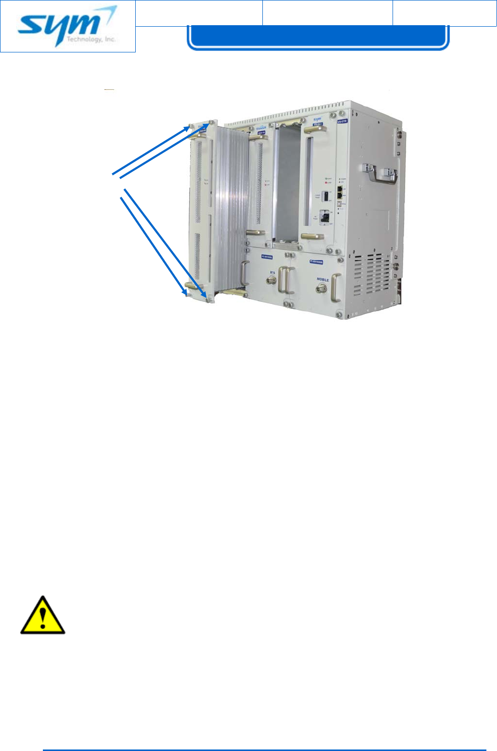
Toreplacean800/900MHzservicecard,referto[Figure4‐1]andproceedasdescribedinthesteps
thatfollow:
(1) SettheDLHPAandULHPAtoOFFattheWebbasdedGUI.
(2) Usingascrewdriver,loosenthefourcaptivescrewssecuringtheservicecardtotheVision
enclosure.
(3) Usethe800/900MHzservicecard’sfronthandlestopulltheservicecardoutoftheenclosure.
CAUTION:Whenremovingtheservicecardfromtheenclosure,supporttheservicecard
sotherearoftheservicecarddoesnotsuddenlydropanddamagetherearD‐sub
conector.Theservicecardweightisapproximately7kg(15.4lbs).
(4) Installthereplacement800/900MHzservicecardinreverseorder.
(5) AligntheguiderailsonthetopandbottomoftheservicecardwithguiderailsintheVision
enclosureandthenslidetheservicecardgentlyintoplace.
CAUTION:Ensuretheservicecardisintheproperorientationbeforeattemptingto
installintotheVisionenclosure.Damagetotherearconnectorscouldoccurifimproperly
installed.
Document No.:
Date:
August 17, 2012 Version: 2.3
UserManual forVision30
Copyrightⓒ2012SYMTechnology,Inc.Allrightsreserved.
5
4
[Figure4‐1]800/900MHzServiceCardReplacement
4.2.3 1900MHzServiceCard
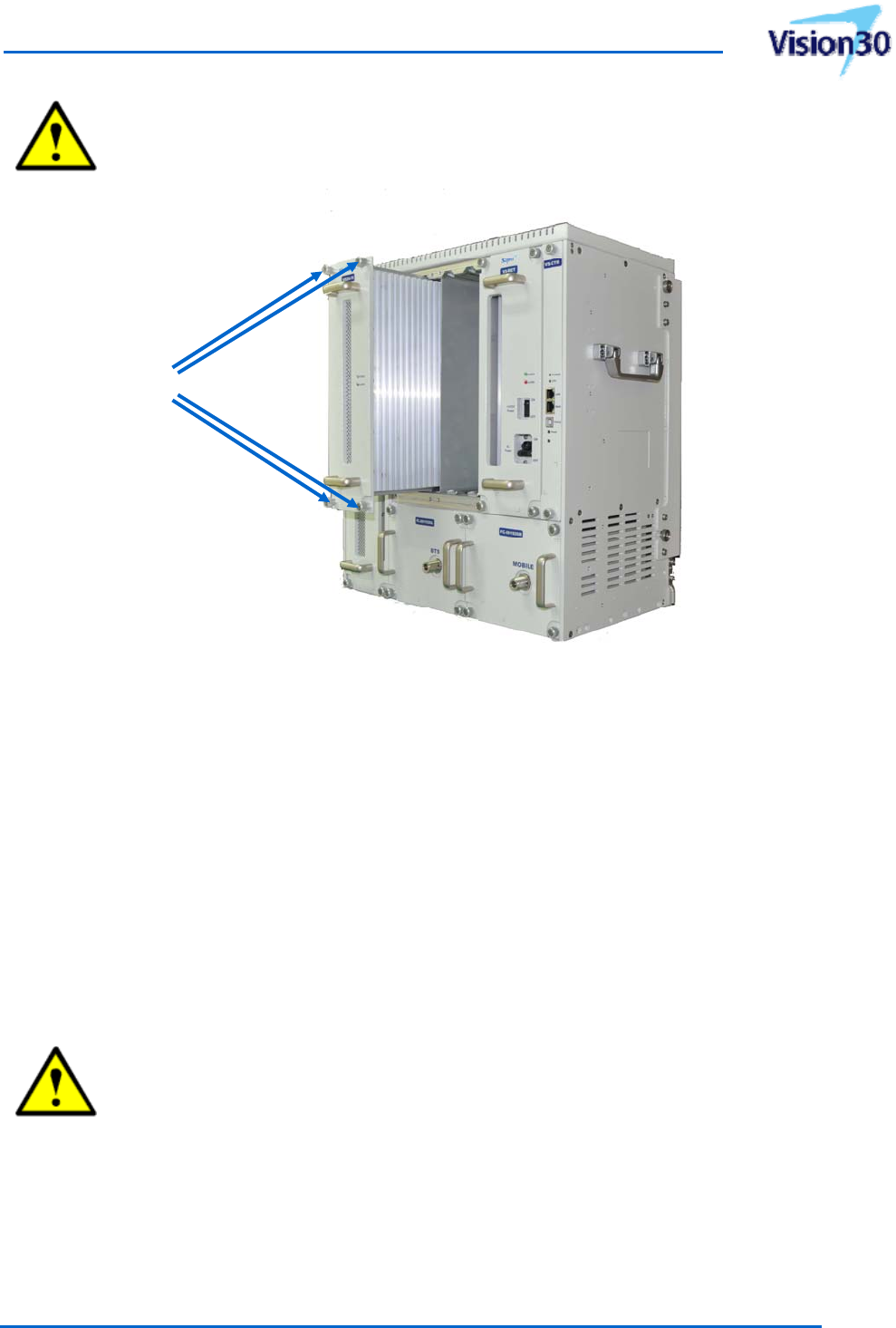
Toreplacea1900MHzservicecard,referto[Figure4‐2]andproceedasdescribedinthestepsthat
follow:
(1) SettheDLHPAandULHPAtoOFFattheWebbasdedGUI.
(2) Usingascrewdriver,loosenthefourcaptivescrewssecuringtheservicecardtotheVision
enclosure.
(3) Usethe1900MHzservicecard’sfronthandlestopulltheservicecardoutoftheenclosure.
CAUTION:Whenremovingtheservicecardfromtheenclosure,supporttheservicecard
sotherearoftheservicecarddoesnotsuddenlydropanddamagetherearD‐sub
conector.Theservicecardweightisapproximately5.7kg(12.6lbs).
(4) Installthereplacement1900MHzservicecardinreverseorder.
(5) AligntheguiderailsonthetopandbottomoftheservicecardwithguiderailsintheVision
enclosureandthenslidetheservicecardgentlyintoplace.
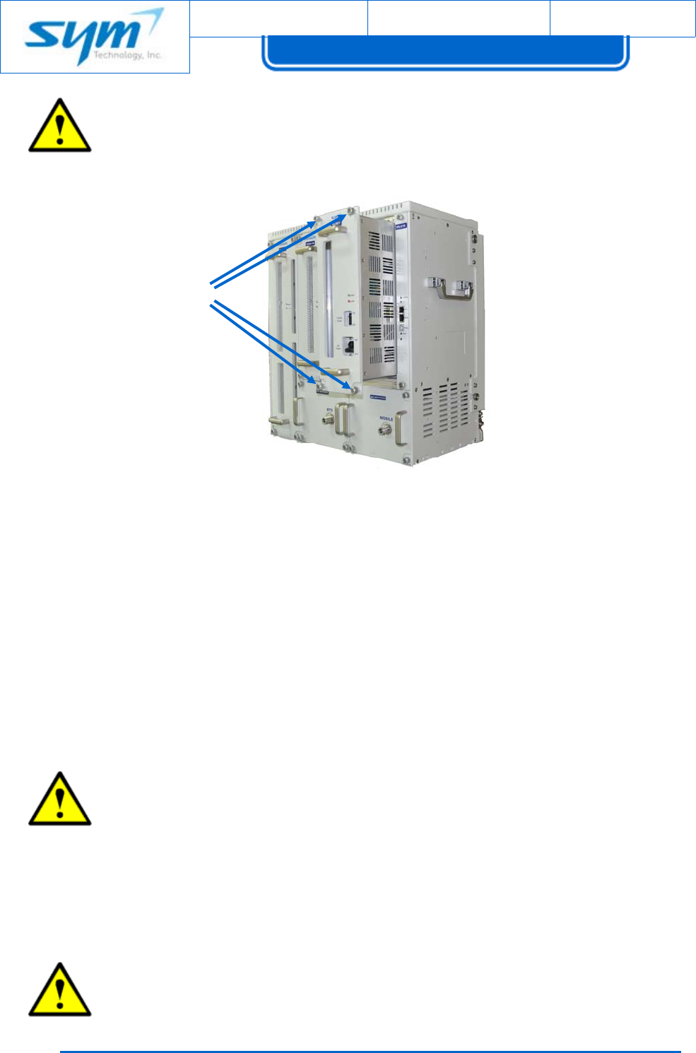
Captive
Screws(4)
UsermanualforSoftwareDefinableRepeater
ProprietaryandStrictlyConfidential55
CAUTION:Ensuretheservicecardisintheproperorientationbeforeattemptingto
installintotheVisionenclosure.Damagetotherearconnectorscouldoccurifimproperly
installed.
[Figure4‐2]1900MHzServiceCardReplacement
4.2.4 Rectifier
Toreplacearectifier,referto[Figure4‐4]andproceedasdescribedinthestepsthatfollow:
(1) SettherectifierACPowerswitchestooFF.
(2) ACmainpowerturnsoffordisconnecttoACpowercord.
(3) Usingascrewdriver,loosenthefourcaptivescrewssecuringtherectifiertotheVision
enclosure.
(4) Usetherectifier’sfronthandlestopulltherectifieroutoftheenclosure.
CAUTION:Whenremovingtherectifierfromtheenclosure,supporttherectifiersothe
rearoftherectifierdoesnotsuddenlydropanddamagetherearDINconector.The
rectifierweightisapproximately5.2kg(11.4lbs).
(5) Installthereplacementrectifierinreverseorder.
(6) AligntheguiderailsonthetopandbottomoftherectifierwithguiderailsintheVision
enclosureandthenslidetherectifiergentlyintoplace.
Captive
Screws(4)
Document No.:
Date:
August 17, 2012 Version: 2.3
UserManual forVision30
Copyrightⓒ2012SYMTechnology,Inc.Allrightsreserved.
5
6
CAUTION:Ensuretherectifierisintheproperorientationbeforeattemptingtoinstall
intotheVisionenclosure.Damagetotherearconnectorscouldoccurifimproperly
installed.
[Figure4‐3]RectifierReplacement
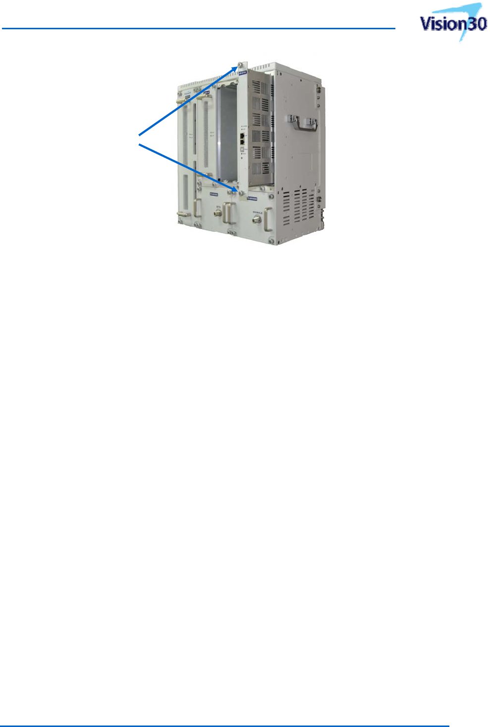
4.2.5 Controller
Toreplaceacontroller,referto[Figure4‐4]andproceedasdescribedinthestepsthatfollow:
(1) SettherectifierACPowerswitchestooFF.
(2) Usingascrewdriver,loosenthetwocaptivescrewssecuringtherectifiertotheVision
enclosure.
(3) Pullthecontrolleroutoftheenclosure.
CAUTION:Whenremovingthecontrollerfromtheenclosure,supportthecontrollerso
therearofthecontrollerdoesnotsuddenlydropanddamagetherearDINconector.
(4) Installthereplacementcontrollerinreverseorder.
(5) AligntheguiderailsonthetopandbottomofthecontrollerwithguiderailsintheVision
enclosureandthenslidethecontrollergentlyintoplace.
CAUTION:Ensurethecontrollerisintheproperorientationbeforeattemptingtoinstall
intotheVisionenclosure.Damagetotherearconnectorscouldoccurifimproperly
installed.
Captive
Screws(4)
UsermanualforSoftwareDefinableRepeater
ProprietaryandStrictlyConfidential57
[Figure4‐4]ControllerReplacement
4.3 ReturnforServiceProcedures
WhenreturningproductstoSYMTechnology,thefollowingprocedureswillensureoptimumresponse.
Manufacturer’sLimitedWarranty
SYMTechnology,Inc.offersalimitedwarrantythattheVisionwillbefreefromdefectsinmaterialor
workmanshipasfollows:
TWO(2)YEARLIMITEDWARRANTY:Foraperiodoftwo(2)yearsfromthedateoforiginalpurchase,
SYMTechnologywill,atitsoption,eitherrepairorreplaceadefectiveVision(withneworrebuilt
parts/replacement).
LIMITEDWARRANTYONREPAIRED/REPLACEDPRODUCTS:AfterSYMTechnologyrepairsorreplaces
theVision,therepairedorreplacedVisionshallbecoveredbywarrantyfortheremainingtimeofthe
originalwarrantyperiodorforninety(90)daysfromthedateofrepair,whicheverislonger.Repairor
replacementmayincludetheuseoffunctionallyequivalentreconditionedunits.Replacedfaultypartsor
componentswillbecomethepropertyofSYMTechnology.
Thislimitedwarrantydoesnotcoverandisvoidwithrespecttothefollowing:(i)Visionwhichhave
beenimproperlyinstalled,maintained,modified,orrepaired;(ii)Visionwhichhavebeensubjectto
outdooruse,misuse,physicaldamage,abnormaluseoroperation,improperhandlingorstorage,
exposuretofire,water,excessivemoistureorextremetemperature;(iii)Visionoperatedoutside
publishedmaximumratings;(iv)Visiononwhichwarrantysealsorproductserialnumbershavebeen
Captive
Screws(2)

Document No.:
Date:
August 17, 2012 Version: 2.3
UserManual forVision30
Copyrightⓒ2012SYMTechnology,Inc.Allrightsreserved.
58
removed,broken,oraltered;(v)costofinstallation,setup,removalorreinstallation;(vi)signal
receptionproblemsornetworkproblems;(vii)damageasaresultoffire,flood,powersurge,lightening,
actsofGodorotheractswhicharenotthefaultofSYMTechnologyandwhichtheVisionisnot
specifiedtotolerate;and(viii)anyVisionwhichhavebeenopened,modified,orrepairedbyanyone
otherthanSYMTechnologyoraSYMTechnologyauthorizedservicecenter.
ObtaininganRMA
AReturnMaterialAuthorization(RMA)numbermustbeobtainedpriortoreturningequipmenttothe
factoryforservice.PleasecontactourRepairDeparentat(626)356‐0817toobtainthisnumber,orFAX
yourrequestto(626)356‐9087.FailuretoobtainthisRMAnumbermayresultindelaysinreceiving
repairservice.
The user that changes or modifications not expressly approved by the party responsible for compliance
could void the user's authority to operate the equipment.

UsermanualforSoftwareDefinableRepeater
ProprietaryandStrictlyConfidential59
5. Specifications
5.1 800/900MHzServiceBand
[Table5‐1]800/900MHzServiceBandSpecifications
ItemDownlinkUplinkDescription
FrequencyBand851‐869/935‐940MHz806‐824/896‐901MHzBW:18&5MHz
AirInterfaceiDEN
BandSelection2non‐contiguousblockssimultaneously
Bandwidth0.25to18MHz/250kHzstep
(Addition:4.6,4.8,6.6,6.8,17.6,17.8MHz)Fcshifting:25kHzstep
OutputPower30dBm
Gain/AdjustmentRange57‐87dB/30dB
BandGainRipple±1.5dBpeaktopeak
RollOffatBandEdge≥65dBcat500kHz
SystemDelay≤7.5us
AdjacentChannelPower>50dBcat25kHz,>55dBcat50kHz,
>65dBcat500kHz,>65dBcat1MHz@singlechannel
OutofbandEmission≤‐13dBm(In‐band),≥65dBc(OutofBand)>FCCrequirements
WaveformQualitySQE≤10%
FrequencyError≤±0.05ppm(±40Hz)
VSWR<1.4:1
UplinkNoiseFigure<5dBatmaximumgain
<12dBatminimumgain

Document No.:
Date:
August 17, 2012 Version: 2.3
UserManual forVision30
Copyrightⓒ2012SYMTechnology,Inc.Allrightsreserved.
60
5.2 1900MHzServiceBand
[Table5‐2]1900MHzServiceBandSpecifications
ItemDownlinkUplinkDescription
FrequencyBand1930‐1995MHz1850‐1915MHz BW:65MHz
AirInterfaceCDMA/LTE
BandSelection3non‐contiguousblockssimultaneously
Bandwidth1.25to20MHz/1.25MHzstepFcshifting:50kHzstep
OutputPower30dBm
Gain/AdjustmentRange60‐90dB/30dB
BandGainRipple±1.5dBpeaktopeak
RollOffatBandEdge≥50dBcat1MHz
SystemDelay≤7.5us
AdjacentChannelPower>45dBcat885kHz,>55dBcat1.98MHz,
<‐13dBmat±2.25MHz(1MHzRBW)@singlechannel
OutofbandEmission<‐13dBm>FCCrequirements
WaveformQualityRho≥0.96
FrequencyError≤±0.05ppm(±90Hz)
VSWR<1.4:1
UplinkNoiseFigure<5dBatmaximumgain
<12dBatminimumgain
ACLR>45dBcat±5MHz
>45dBcat±10MHz LTEsignal(E‐TM1.1)
EVM/FrequencyError≤5%differencefromreferencesource/<±0.05
ppm+12HzLTEsignal(E‐TM3.1)
Operatingband
UnwantedEmission
<‐10dBmat±2.55‐7.55MHz(100kHzRBW)
<‐14dBmat±7.55‐12.55MHz(100kHzRBW)
<‐15dBmat±13‐15MHz(1MHzRBW)
LTEsignal(E‐TM1.1)