SZ DJI TECHNOLOGY GL6D10A1609 C1 User Manual
SZ DJI TECHNOLOGY CO., LTD C1
Contents
- 1. Users Manual
- 2. User Manual
User Manual
User Manual
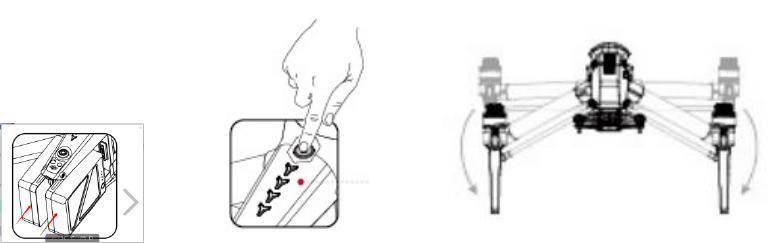
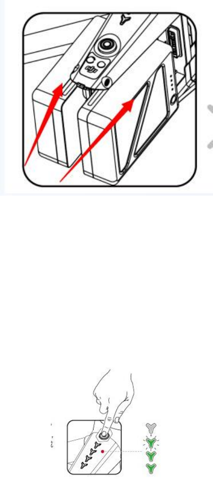
Preparing Aircraft and Battery
Exiting Packing Mode
The aircraft enters Packing Mode to enable easy packing during transportation. It is
required to disable Packing Mode when using the aircraft on its first use.
1. Plug in both Intelligent Flight Batteries onto the aircraft. Powering on to exit
Packing Mode.
2. Press and release on the power button on the Intelligent Flight Batteries for up to
5 times to exit Packing Mode.
Installing Camera and Gimbal
Power off the aircraft.
1. Press and hold the mounting button on the gimbal mount.
2. Align the white dot on the camera connector with the red dot on the gimbal mount,
follow by mounting the camera onto the gimbal mount.
3. Rotate the locking ring on the camera so that the red dot on the camera is aligned with
the red dot on the gimbal mount.
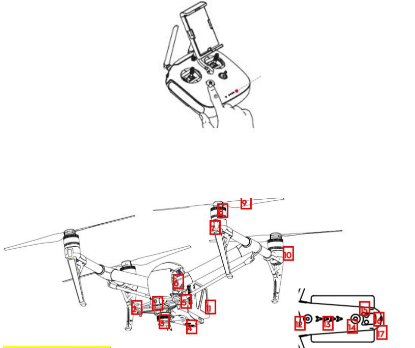
Using the Remote Controller
Press and release the power button on the remote controller, wait for 3 seconds then press
and hold the power button to power on the remote controller.
Aircraft Diagram
1. FPV (First Personal View) Camera
2. Obstacle Sensing System
3. Quick Release Mount
4. Vision Positioning System
5. Landing Gear Servo
6. Graphic Processing System
7. Front LED
8. Motor
9. Propellers
10. Rear LED
11. Intelligent Flight Battery
12. Power Button
13. Battery Level Indicator
14. Battery Eject Button
15. Top Sensor
16. Aircraft Status Indicator
17. SSD Port
18. USB Port
20. USB Mode Button
21. Link Button
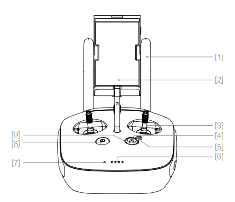
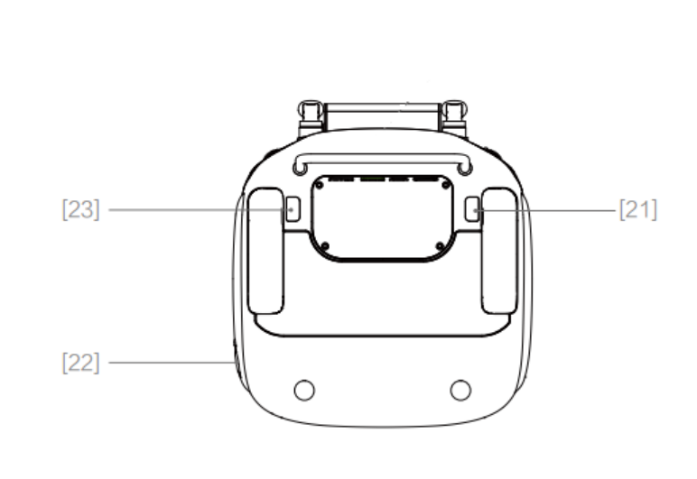
Remote Controller Diagram
[1] Antennas
Relays aircraft control and video signal.
[2] Mobile Device Holder
Securely mounts your mobile device to the remote controller.
[3] Control Stick
Switch between Mode 2 and
Mode 1 by using the DJI GO app.
[4] RTH Button
Press and hold the button to initiate Return to Home (RTH).
[5]Transformation Switch
This switch comprises of two options.
Toggle this switch to lower or retract the landing gear.
[5] Battery Level LEDs
Displays the battery level of the remote controller.
[7]Status LED
Displays the remote controller's system status.
[7] Power Button
Used to turn the remote controller on and off.
[8] RTH LED
Circular LED around the RTH button displays RTH status.
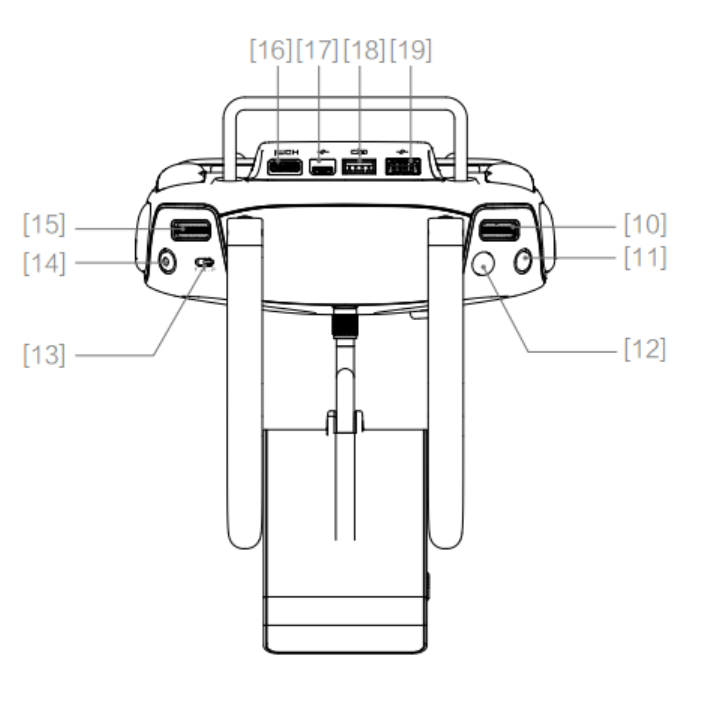
[10] Camera Settings Dial
Turn the dial to adjust camera settings.
[11] Pause Button
Press this button to pause the current operations including Tapfly, Follow me.
[13]Shutter Button
Press to take a photo.
[12] Flight Mode Switch
Use this switch to switch between
A(Atti), S(Sports) and P(Positioning) mode.
[14]Record Button
Press to start recording video.
[15] Gimbal Dial
Tilt Gimbal
[16] HDMI Port
Use this port to relay HDMI signal to HDMI devices
[17] Micro USB Port
Reserve for future use.
[18] CAN Port
Reserve for future use.
[19] USB Port
Connect to mobile device for running the DJI GO app.
[21] C1 Button
[22] Power Port
Connect to the Charging Hub to charge the battery of the remote controller.
[23] C2 Button
Using the Remote Controller
Press once to check the battery level from the battery level LEDs. Follow the steps below
to turn on your remote controller:
1. The Battery Level LEDs will display the current battery level.
2. Press once, then again and hold to turn on/off Remote Controller.
3. Repeat Step 2 to turn off the remote controller.
Battery
Turning ON/OFF
Slide both the batteries into the battery slots on the rear of the aircraft until it is securely
attached on the slots.
Turning On: Press the Power Button once, then press again and hold for 2 seconds to turn
on. The Power LED will turn red and the remote controller system status screen will
display the current battery level.
Turning Off: Press the Power Button once, then press again and hold for 2 seconds to turn
off. Power level indicators turn off when it is power down. The battery power LED will flash
when powering off the Phantom to allow automatically stopping of a recording during the
event recording wasn’t stopped.
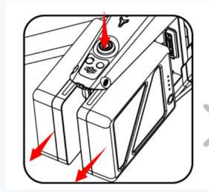
Remove the Intelligent Flight Battery
Press the curricula Battery Eject button to eject both the batteries from the aircraft.
Charging the Batteries
1. Connect the Battery Charger to a power source (100-240 V 50/60 Hz).
2. Connect the one end of the Battery Charger to the supplied Charging Hub to start
charging.
3. The Battery Level Indicator will display the current battery level as it is charging.
4. The Intelligent Flight Battery is fully charged when the Battery Level Indicators are all off.
The Battery Level Indicators will turn off when charging is complete. Detach the batteries
from the Charging Hub.
Allow its temperature to drop to room temperature before storing it for an extended
period.
The charger will stop charging the battery if the battery cell’s temperature is not within the
operating range (5°C to 40°C ).
Powering on aircraft and remote controller
1. Power on the remote controller before powering the aircraft.
2. Launch the DJI GO app and enter “Camera” view.
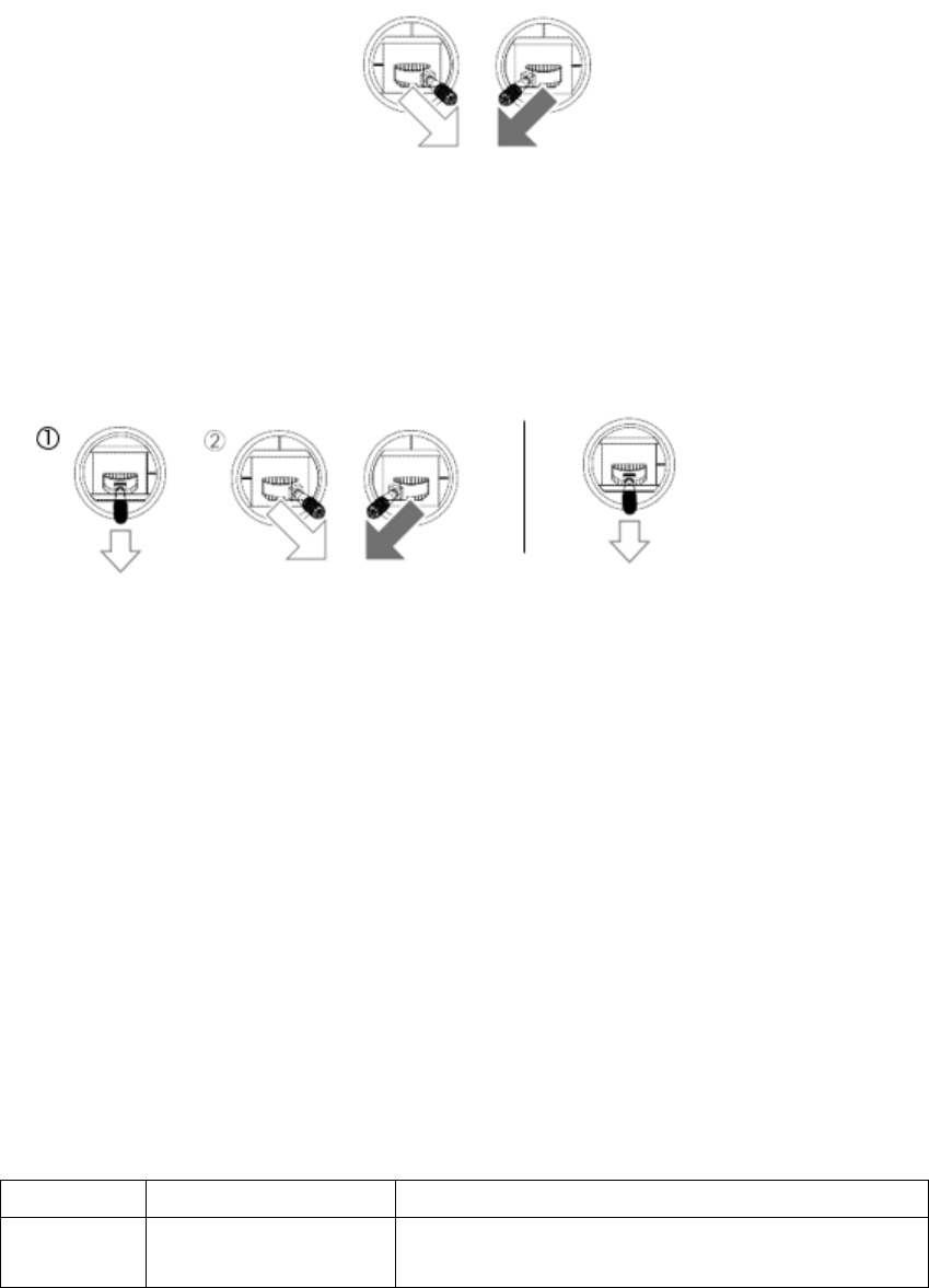
Starting/Stopping the Motors
Starting the Motors
A Combination Stick Command (CSC) is used to start the motors. After the motors start,
release both control sticks.
Stopping the Motors
There are two methods to stop the motors. When Phantom 4 has landed, push the left
stick down , then conduct the same CSC that was used to start the motors, as described
above . Release both sticks once motors stop. When the aircraft has landed, push and hold
the left stick down.
Specifications
Model
T650A
Aircraft
Weight (Battery &
Propellers Included)
3375g

Diagonal Distance
(Propellers Excluded)
605mm
Max Ascent Speed
6 m/s ( Sport mode )
Max Descent Speed
4 m/s(descending)/ 7m/s(diving)
Max Speed
20 m/s ( Sport mode )
Max Service Ceiling
Above Sea Level
6000m
Flight Time
25miin
Operating
Temperature
-10°C to 40°C
Satellite Positioning
Systems
GPS/GLONASS
Hovering Precision
Vertical +/- 0.1 m (VPS enabled);+/- 0.5 m
Horizontal: +/- 0.3 m (VPS enabled);+/- 1.5 m
Gimbal
Controllable Range
Pitch: -90° to +30° roll: -90° to +30° pan: ±320°
Stabilization
3-axis (pitch, roll, pan)
Obstacle
Sensing
System
Obstacle Sensing
Range
Front: 0.7 - 30 m 0-8m (Top ToF sensing range)
0-4m
FOV
Forward sensing: Horizontal Range: 60°,Vertical
Range: 54° ±5°
Detecting Range
Forwarding: 10 Hz,Upward: 20Hz
Operating
Environment
Front view: Surfaces with clear patterns and
adequate lighting (lux > 15) surface with
distinctive patterns
Vision
Positioning
Status
Velocity Range
≤ 22.4mph (36kph) at 6.6ft (2m) above ground
Altitude Range
0m to10m
Operating Range
0m to10m
Detecting Frequency
10 Hz
Operating
Environment
Surfaces with clear patterns and adequate lighting
(lux > 15)
Altitude
Sensing
System
Altitude Range
5cm-500cm
Detecting Range
1 cm
Detecting Frequency
20Hz
Operating
Environment
Surface with no sound absorbing features.
Model
GL6D10A

Remote
Controller
Max Transmission
Distance
FCC: 5000 m ;CE: 3500 m (2.4 GHz no
interference, unobstructed)
FCC: 5000 m ;CE: 2000 m (5.8 GHz no
interference, unobstructed)
Operating
Temperature
0°C to 40°C
Battery
6000 mAh LiPo 2S
Operating Voltage
7.4V @ 1.2A
FCC Compliance Notice
This device complies with Part 15 of the FCC Rules. Operation is subject to the following two
conditions: (1) This device may not cause harmful interference, and (2) This device must accept
any interference received, including interference that may cause undesired operation.
Any changes or modifications not expressly approved by the party responsible for compliance
could void the user’s authority to operate the equipment.
This equipment has been tested and found to comply with the limits for a Class B digital device,
pursuant to part 15 of the FCC Rules. These limits are designed to provide reasonable protection
against harmful interference in a residential installation. This equipment generates, uses and can
radiate radio frequency energy and, if not installed and used in accordance with the instructions,
may cause harmful interference to radio communications. However, there is no guarantee that
interference will not occur in a particular installation. If this equipment does cause harmful
interference to radio or television reception, which can be determined by turning the equipment
off and on, the user is encouraged to try to correct the interference by one or more of the
following measures:
—Reorient or relocate the receiving antenna.
—Increase the separation between the equipment and receiver.
—Connect the equipment into an outlet on a circuit different from that to which the receiver is
connected.
—Consult the dealer or an experienced radio/TV technician for help.
RF Exposure Information
T650A complies with FCC radiation exposure limits set forth for an uncontrolled environment. In
order to avoid the possibility of exceeding the FCC radio frequency exposure limits, human
proximity to the antenna shall not be less than 20cm during normal operation.
For model GL6D10A, SAR tests are conducted using standard operating positions accepted by the
FCC/IC with the device transmitting at its highest certified power level in all tested frequency
bands, although the SAR is determined at the highest certified power level, the actual SAR level
of the device while operating can be well below the maximum value. Before a new model is a
available for sale to the public, it must be tested and certified to the FCC/IC that it does not
exceed the exposure limit established by the FCC/IC, Tests for each product are performed in
positions and locations as required by the FCC/IC. For Handheld operation, this device has been
tested and meets the FCC RF exposure guidelines when used with an accessory designated for
this product or when used with an accessory that contains no metal.
IC RSS Warning
This device complies with Industry Canada licence-exempt RSS standard (s). Operation is subject
to the following two conditions: (1) this device may not cause interference, and (2) this device
must accept any interference,including interference that may cause undesired operation of the
device.
Le présent appareil est conforme aux CNR d'Industrie Canada applicables aux appareils radio
exempts de licence.
L'exploitation est autorisée aux deux conditions suivantes:
(1) l'appareil ne doit pas produire de brouillage, et
(2) l'utilisateur de l'appareil doit accepter tout brouillage radioélectrique subi, même si le
brouillage est susceptible d'en compromettre le fonctionnement.
IC Radiation Exposure Statement:
This equipment complies with IC RF radiation exposure limits set forth for an uncontrolled
environment. This transmitter must not be co-located or operating in conjunction with any other
antenna or transmitter.
T650A should be installed and operated with minimum distance 20cm between the radiator&
your body.
Cet appareil est
conforme aux limitesd'exposition de rayonnement RF IC établiespour un environnement non
contrôlé.
Cetémetteur ne doit pas être co-implanté oufonctionner en conjonction avec toute autreantenne
ou transmetteur.
T650A doit être installé et utiliséavec une distance minimale de 20cm entre leradiateur
& votre corps.
Any Changes or modifications not expressly approved by the party responsible for compliance
could void the user’s authority to operate the equipment.
KCC Warning Message
“해당무선설비는 운용 중 전파혼신 가능성이 있으므로 인명안전과 관련된 서비스는
할 수 없습니다.”
“해당 무선설비는 운용 중 전파혼신 가능성이 있음”
NCC Warning Message
低功率電波輻射性電機管理辦法
第十二條 經型式認證合格之低功率射頻電機,非經許可,公司、商號或使用者均不得擅自
變更頻率、加大功率或變更原設計之特性及功能。
第十四條 低功率射頻電機之使用不得影響飛航安全及干擾合法通信;經發現有干擾現象時,
應改善至無干擾時方得繼續使用。前項合法通信,指依電信法規定作業之無線電通信。低功
率射頻電機須忍受合法通信或工業、科學及醫療用電波輻射性電機設備之干擾。
EU Compliance Statement: SZ DJI TECHNOLOGY CO., LTD. hereby declares that this device is in
compliance with the essential requirements and other relevant provisions of the R&TTE Directive.
A copy of the EU Declaration of Conformity is available online at www.dji.com/euro-compliance
EU contact address: DJI GmbH, Industrie Strasse. 12, 97618, Niederlauer, Germany