SZ DJI TECHNOLOGY IG8101508 AIR UNIT User Manual
SZ DJI TECHNOLOGY CO., LTD AIR UNIT
UserManual.wiki
>
SZ DJI TECHNOLOGY
>
IG8101508 User Manual
User Manual
Navigation menu
Upload a User Manual
Namespaces
Wiki Guide
HTML
PDF
Info
Views
User Manual
Discussion / Help
Navigation
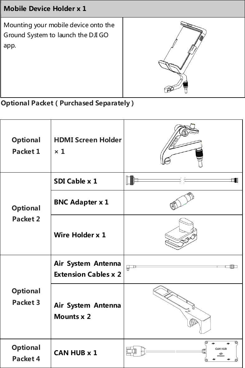
![GIMBAL Cable x 1 Connect to Air system GIMBAL port, one end for DJI HD gimbal, the other for CAN port. AV Cable x 1 Connect camera’s AV output to Air system AV port. HDMI Cable x 1 Connect camera’s HDMI output to Air system HDMI port.. USB Cable x 1 Upgrade the air system. Ground System Cables Charger x 1 Charging for the Ground System. Comment [M1]: 电源线?](https://usermanual.wiki/SZ-DJI-TECHNOLOGY/IG8101508/User-Guide-2759233-Page-5.png)

![1. Introduction 1.1 Air System Diagram [1] HDMI IN Port Connect to HDMI input device. M aximum input rate is 1920*1080@60fps. [2] AV Port Connect to AV input device. [3] GIMBA L PORT Connect this port to the G7 port on a DJI HD gimbal or to other ports for the fun ctions listed below: a) Power su pply: (V+,V-) On-board battery (9~12V) power connection. b) CAN-Bus: (L,H) Access to the flight controller information. For DJI HD gimbal users, connect to the CAN-Bus port (for DJI A2/WooKong-M user, use the CAN 2 Bus port) on the flight controller with a seperated CAN bus cable. c) DVSB: (G-,+) DVSB video input from DJI HD gimbal. [4] DBUS Port Conn ect built in receiver interface to DJI flight control system DBUS port, usually located on the main controller labled X2. No other receiver requried when DBUS is used. [5] UPGRADE Port Connect to PC to upgrade firmware of the air system using Lightbridge 2 Assistant. [6] LINK Buttom Press to link air system with Ground System. [7] CONTROL Indicator Indicate the communtation status of the air and Groun d Systems.](https://usermanual.wiki/SZ-DJI-TECHNOLOGY/IG8101508/User-Guide-2759233-Page-8.png)
![Ind ica tor Description Instruction Linking in progress. Link button has been pressed. Air system is attempting to link with Ground System. Signal detected but not linked. Link requ ired. Successful link. Normal. No detected signal. Power on Ground System. Check distance between ground and air systems. [8] VIDEO Indicator Indicate video source transmission status. Ind ica tor Description Instruction AV/HDMI signal detected and functioning normally. Normal. AV/HDMI signal detected. Transmission f ailed. Air system or Ground System power cycle required. No video source detected or not supported by Lightbridge 2. Check camera and connection. [9] Ventilation inlet Do not obstruct ventilation fan outlet to ensure maximum cooling efficiency. [10] Antenna Port](https://usermanual.wiki/SZ-DJI-TECHNOLOGY/IG8101508/User-Guide-2759233-Page-9.png)
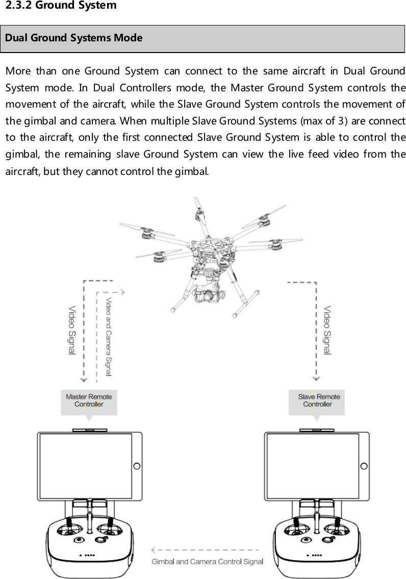
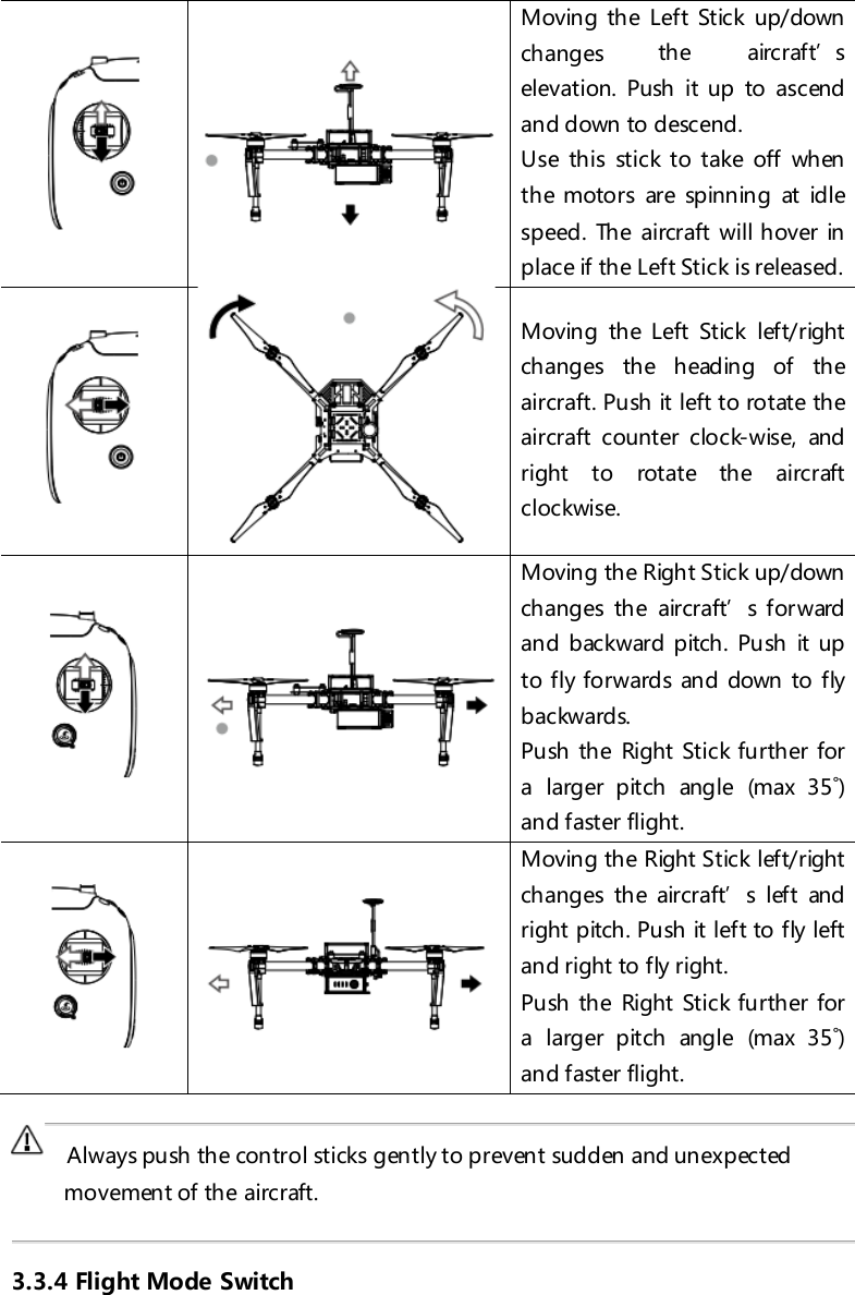
![1.2 Ground System Diagram [1] A ntenna s Relays aircraft control and video signal. [2] Mobile Device Holder Port Mounting place for the mobile device holder. [3] Control Stick Controls the aircraf t mo vemen t. [4] Return Home (RTH) Button Press and hold the button to initiate Return to Home (RTH). [5] Transformation Switch Customizable button in flight controller assistant. [6] Battery Level LEDs Displays the current battery level. [7] Sta tu s LED Indicates the connection status of the air and Ground System. Sta tus LED Alarm Gro und System Sta tus The Ground System is set as Master but is not connected to the aircraft. The Ground System is set as Master and connected to the aircraft. The Ground System is set as Slave but is not connected to the aircraft. The Ground System is set as S lave and](https://usermanual.wiki/SZ-DJI-TECHNOLOGY/IG8101508/User-Guide-2759233-Page-10.png)
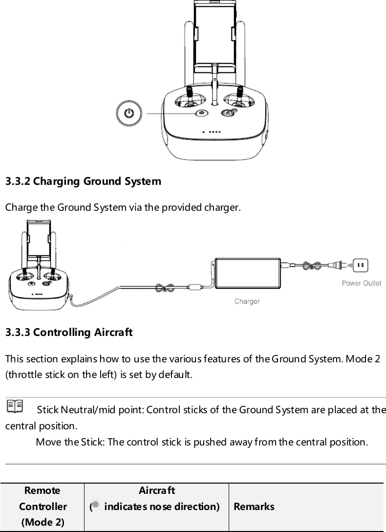
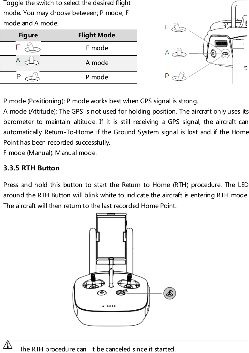
![connected to the aircraft. Ground System err or. [8] Power Button Used to power on or power off the Groun d System. [9] RTH LED Circular LED around the RTH button displays RTH status. RTH LED Sound Ai rcra ft Sta tus Return-to-Home procedure is activated. S end in g Retu rn-to-Home command to the aircraft. Return-to-Home is in progress. [10] Camera Settings Dial Customizable button in flight controller assistant. [11] Playback Button Customizable button in flight controller assistant. [12] Shutter Button Customizable button in flight controller assistant. [13] Flight Mode Switch Customizable switch in flight controller assistant to set manual, attitude or GPS mode.](https://usermanual.wiki/SZ-DJI-TECHNOLOGY/IG8101508/User-Guide-2759233-Page-11.png)
![[14] Video Recording Button Customizable button in flight controller assistant. [15] Gimbal Dial Customizable dial in flight controller assistant [16] Re served Expan sion Por t Reserved port. [17] SDI Port Connect a SDI display device. [18] HDMI OUT Port Connect an HD compatible monitor. [19] USB Port Connect to mobile device to laun ch DJI GO app, which displays the live camera preview and OSD information. [20] GPS Module Used to pin point the location of the Ground System. [21] Back Le ft Button Customizable button in flight controller assistant. [22] Power Port Connect to a power source to charge the Ground System’s internal battery. [23] Back R ight B utton Customizable button in flight controller assistant.](https://usermanual.wiki/SZ-DJI-TECHNOLOGY/IG8101508/User-Guide-2759233-Page-12.png)