SZ DJI TECHNOLOGY R400BS1806 D-RTK 2 High-Precision GNSS Mobile Station User Manual
SZ DJI TECHNOLOGY CO., LTD D-RTK 2 High-Precision GNSS Mobile Station
User Manual
D‐RTK2High‐PrecisionGNSSMobileStation
UserGuide
V1.0
2018.06
Disclaimer
ThankyouforpurchasingD‐RTKTM2(hereinafterreferredtoasthe“Product”).
ReadthisdisclaimercarefullybeforeusingthisProduct.ByusingthisProduct,you
herebyagreetothisdisclaimerandsignifythatyouhavereaditfully.Pleaseuse
thisProductinstrictaccordancewiththemanualandbesuretopayattentionto
theWarnings.SZDJITECHNOLOGYCO.,LTD.,anditsaffiliatedcompaniesassume
noliabilityfordamage(s)orinjuriesincurreddirectlyorindirectlyfromusing,
installingorrefittingthisProductimproperly,includingbutnotlimitedtousing
non‐designatedaccessories.
DJITMisatrademarkofSZDJITECHNOLOGYCO.,LTD.(abbreviatedas“DJI”)and
itsaffiliatedcompanies.Namesofproducts,brands,etc.,appearinginthis
manualaretrademarksorregisteredtrademarksoftheirrespectiveowner
companies.ThisProductandmanualarecopyrightedbyDJIwithallrights
reserved.NopartofthisProductormanualshallbereproducedinanyform
withoutthepriorwrittenconsentorauthorizationofDJI.
Thisdisclaimerisproducedinvariouslanguages.Intheeventofdivergence
amongdifferentversions,theChineseversionshallprevailwhentheProductin
questionispurchasedinChina,andtheEnglishversionshallprevailwhenthe
Productinquestionispurchasedinanyotherregion.
Warnings
1.MG‐12000S/MG‐12000PbatteriescanbeusedforR400BS.Pleasepurchase
themseparatelyandDONOTuseotherbatterymodels.
2.OnlyusetheR400BSinthecorrespondingfrequencybandandinaccordance
withlocallawsandregulations.
3.DONOTbendorfoldthecablesexcessively.
4.EnsurethattheR400BSisperfectlylevelwhenmountedandplaced.
5.Onlyoperateinanopenenvironmentfreefromradiointerference.Turnoff
nearbydevicesusingthesamefrequenciesastheD‐RTKBaseStation(e.g.radio
transceivers).
6.Ensurethattheantennasofallthedevicesusedareunobstructedwheninuse.
7.OnlyusegenuineDJIpartsorpartscertifiedbyDJI.Unauthorizedpartsorparts
fromnon‐DJI‐certifiedmanufacturersmaycausethesystemtomalfunctionand
compromisesafety.
8.EnsurethattheR400BSanditscomponentsarefreefromcontamination(e.g.
water,oil,soilandsand).
9.DONOTattempttodisassembleanypartoftheR400BSthathasalreadybeen
mountedpriortoshipping.
10.Handlethesharpendsofthetripodwithcaution.
11.Takenecessarymeasurestoprotectthebasestationandbatteriesfromwater
inrain,snow,and/orthunderstorms.Operatewithcautioninsevereweather
conditions.
ProductProfile
Introduction
D‐RTK2High‐precisionGNSSmobilestation(abbreviatedasR400BSmobile
station)isanewhigh‐precisionsatellitesignalreceiverthatsupportsGPS,
Compass,GLONASS,andGalileo4systemswith9‐bandsatellitesignalreception,
withbuilt‐inOCUSYNCTMWi‐Fi,LANandCANDatatransmissionlinksare
convenientforuserstouseindifferentapplicationscenarios.TheR400BSmobile
stationcanbeusedasanRTKmobilebasestationtoincreasethepositioning
accuracyofanaircraftequippedwithaDJIRTKpositioningsystem(suchas
MG‐1PRTK,PHANTOMTM4RTK,etc.)frommeterstocentimeters.Itcanprovides
stronganti‐magneticinterferencetoensurereliableoperationflightunderstrong
magneticinterferenceenvironmentssuchashigh‐voltagelinesandmetal
construction.TheR400BSmobilestationcanalsobeusedasaHandheld
Mapping*forhand‐heldsurveyingandmapping,engineeringloftingandother
purposes,enablingmoreaccuratefarmplanning.Inaddition,R400BScanalsobe
usedasDJIPositionService(DPS)*toquicklyestablishnetworkRTKservices.
*Comingsoon.
Note:TheconstructionofnetworkRTKservicesmustcomplywiththelocallaws,
regulationsandqualificationrequirements.DJIonlyprovidestechnicalservices.
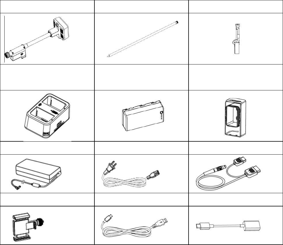
In the Box
R400BSBody1ExtensionRod1MGBatteryHolder1
ChargingHub1IntelligentBattery
(WB37)2BatteryCover1
PowerAdapter1ACCable1MGPowerCable1
MobilePhoneHolder1USB‐CCable1USB‐COTGCable1
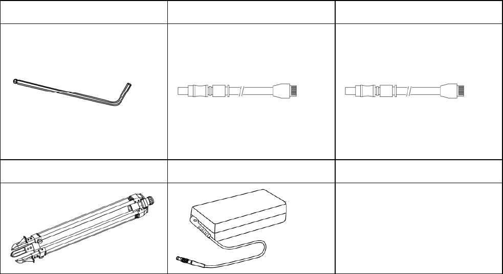
HexagonWrench1LANCable1*CANCable1*
Tripod1*PowerAdapterII1**Manuals
*Optionalitems.
**OptionalitemwhentheR400BSisworkingasaCORSstation.
Overview
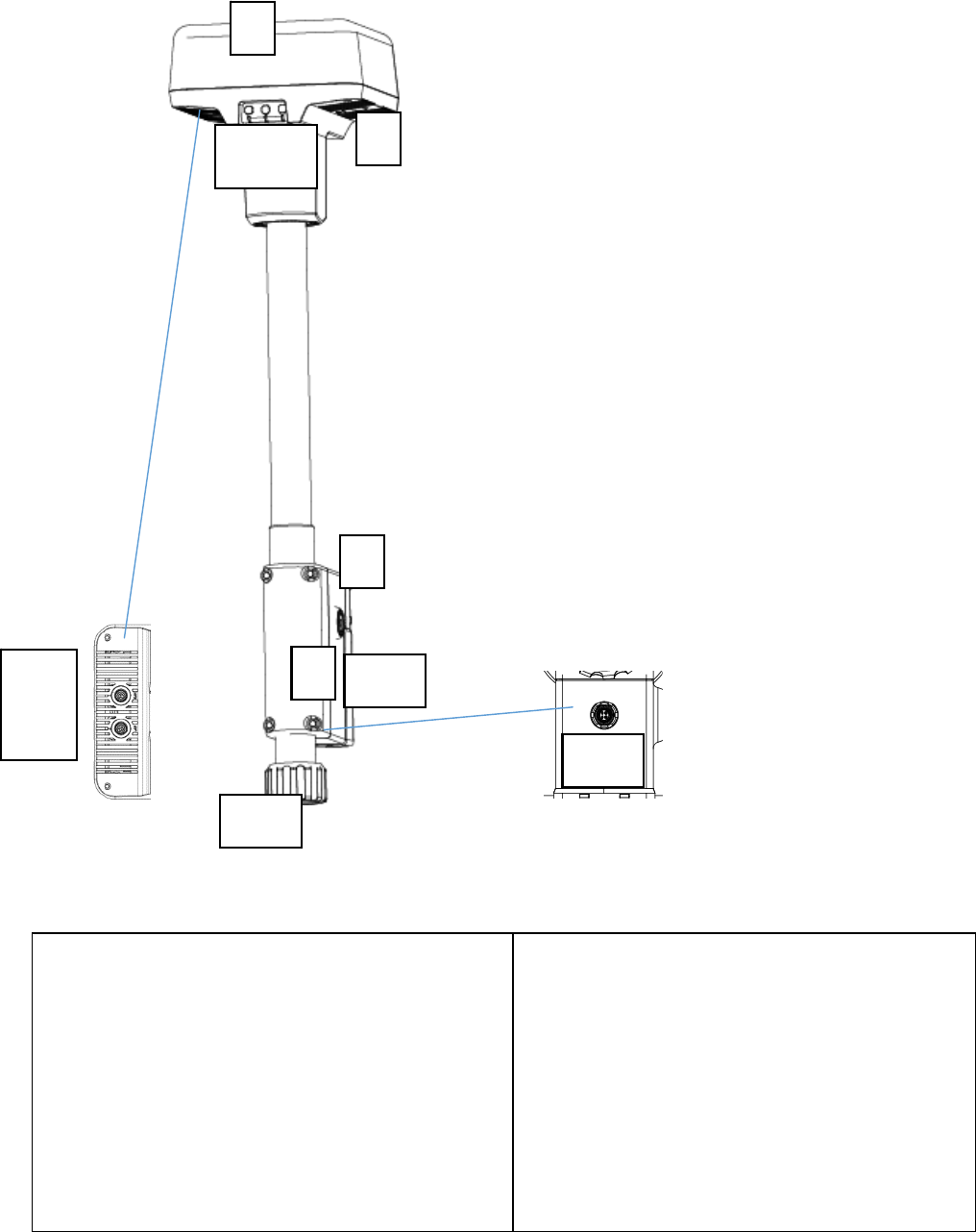
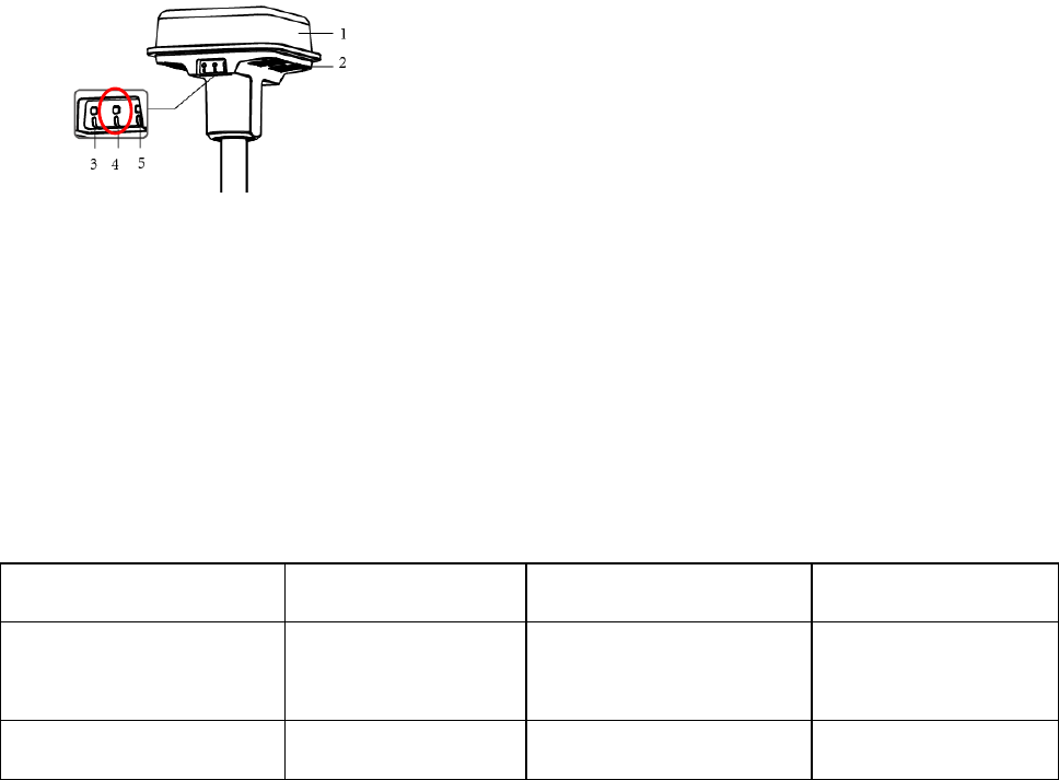
R400BSBody
1.R400BSAntenna
2.USB‐CPort
3.LinkButtonandIndicator
4.PowerButtonandIndicator
5.WorkingModeButtonandIndicator
6.CANPort
7.LANPort
8.MobilePhoneHolderMounting
Port
9.BatteryCompartment
10.BatteryCover
11.LockingNut
12.ExternalPowerPort
1
2
345
8
1
0
9
6
7
11
12
Preparing
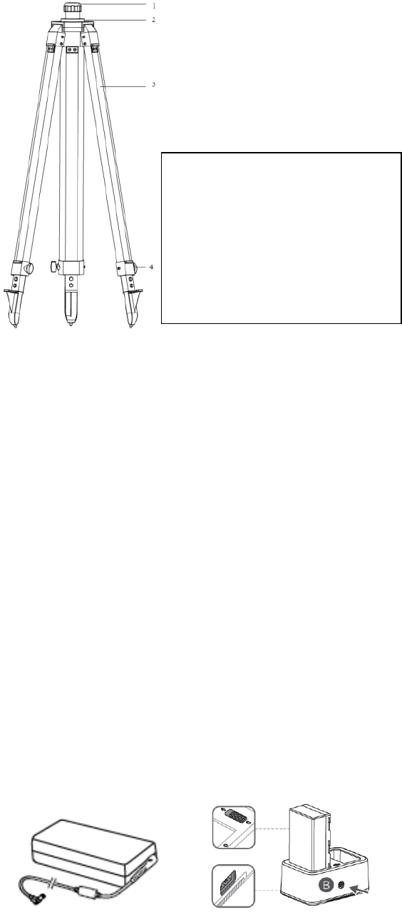
Charging the Battery
Placethebatteryintothecharginghub,andconnectthebatterychargertothe
charginghub,thenconnectthebatterychargertoapoweroutlet(100‐240V,
50/60Hz).TheStatusLEDturnssolidgreenwhenfullycharged.Atthesametime,
thebuzzerwillbeginbeepingwhenchargingiscomplete.Removethebatteryor
turnofftheBuzzerSwitchtostopit.
Tip:
RefertotheChargingHub(WCH2)UserGuideformoredetails.
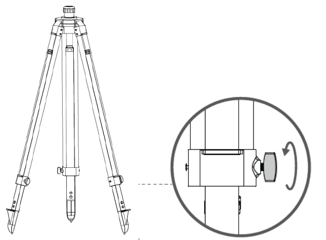
Tripod
1.R400BSSleeve
2.MountBase
3.RetractableLegs
4.Knobs
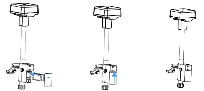
Mounting the Battery
Mounting the Dongle
Important:
OnlyuseaDJIapproveddongle.
Thedonglesupportsvariousnetworkstandards.UseaSIMcardthatis
compatiblewiththechosenmobilenetworkproviderandselectamobiledata
planaccordingtotheplannedlevelofusage.
UsethedongleandtheSIMcardinaccordancewiththeirmanuals.
1.RemovetheDonglecoverwiththeM2.5HexagonWrench.
2.
InserttheSIMcardintothedongleandtheninsertthedongleintothe
compartment.Testtoensurethattheyfunctionproperly.*
3.Re‐mountthedonglecompartmentcover.
*Testprocedure:TurnontheR400BS.IntheDJIMGappselectNetwork
Diagnostics.Ifthestatusesofallthedevicesinthenetworkchainareshownin
greenthedongleandSIMcardarefunctioningproperly.
Turning on/ Turning off the R400BS
Pressandholdonthepowerbuttontoturnon/turnofftheR400BS.
Switching the Working Modes
Pressandholdontheworkingmodebuttontoswitchtheworkingmodesand
theindicatorblinksyellowoncetoindicatethattheswitchissuccessful.
Themodeindicatorblinkingcountinthegreenlightcycleindicatesthedifferent
workingmodes.
WorkingMode1WorkingMode2*WorkingMode3*
ModeNameMobileStationStationaryStation
(CORS)
HandheldMapper
GreenBlinkingCountOnceTwiceThreeTimes
*Comingsoon.
Linking
LinkingProcedures
R400BScanworkwithMG‐1PRTKandPhantom4RTKtogetherasaMobile
Station.LinkbetweentheR400BSandtheremotecontrollerofMG‐1PRTKand
Phantom4RTKisrequired,andtheProcedureisalmostthesameforMG‐1PRTK
andPhantom4RTK.BelowProceduresusetheMG‐1PRTKforexample.
1.TurnontheR400BS,waitfortheindicatortoturngreenon,andthenpressand
holdontheworkingmodeswitchtoentertheWorkingMode1.
2.PowerontheMG‐1PRTKremotecontrollerandensurethattheDJIMGAppis
available.
3.GototheDJIMGapp>OperationView>.First,taponthesidebarto
ensurethattheConnectedDJIDeviceTypeissetto“BaseStation."Next,tapthe
RTKtagonthesidebar>“RTKLinking.”Asoundemittedfromtheremote
controllerindicatesthattheremotecontrollerhasinitiatedlinking.
4.PresstheLinkButtonontheR400BSandthelinkindicatorblinksalternately
redandgreenindicatesthattheR400BShasinitiatedlinking.
5.BothremotecontrollerindicatorandD‐RTKlinkindicatorturngreenindicates
successfullinking.
6.RefertotheMG‐1PRTKUserManualtolearnhowtolinktheremote
controllerandtheaircraft.
LinkIndicatorDescription
ThelinkindicatorblinksalternatelyredandgreenindicatesthattheR400BShas
initiatedlinking.
ThelinkindicatorblinksasbelowindicatesthattheR400BShasquittedlinking.
WorkingMode1and3Status
GreenonOcusyncsignalquality>70%
FastgreenblinkingOcusyncsignalquality:35%‐70%
SlowgreenblinkingOcusyncsignalquality:≤35%
RedonOcusyncsignalquality=0
WorkingMode2Status
GreenonNetworkconnected
RedonNetworkdisconnected
Usage
Mounting the R400BS Mobile Station
Chooseanappropriatelocationtosetupthebasestation.Markthelocationto
ensurethatthebasestationcanbeplacedatthesamelocationaftermovingit.
1.Unfoldthetripod,stretchthethreeretractablelegstothedesiredlength,and
thentighteneachofthethreeknobs.
2.AttachtheR400BSbodyontotheExtensionRod,andthenplugtheExtension
Rodintothetripodandtightenthebasestationsleeve.
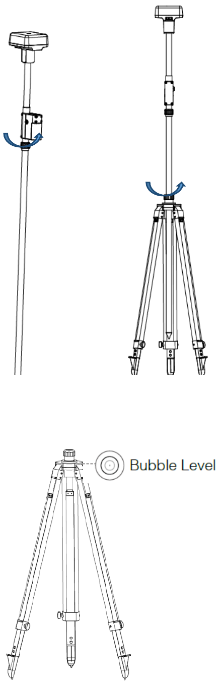
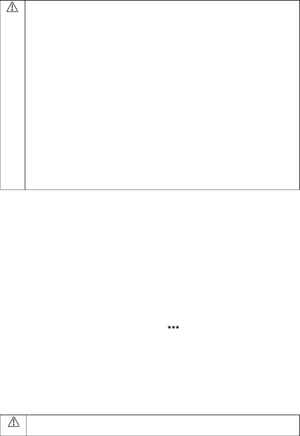
3.Adjusttheangleofeachretractablelegsothatthebubbleofthebubblelevel
onthemountbaseislocatedwithintheblackcircle(viewedfromthetopofthe
bubblelevelvertically)whilekeepingthetripodsecure.
DONOTchangethepositionorangleofthetripodorbasestationafter
thetripodhasalreadybeenadjustedtobelevel,orelseitshouldbe
readjusted.
Thesetupenvironmentrequiresawildvisionfield.Ensurethatthere
arenoobstructions(trees,buildings)above15°aroundtheR400BS
antennatoavoidtheGNSSsignalbeingabsorbedorblocked.
Thesetupenvironmentshouldbeatleast200metersawayfrom
high‐powerradioemissionsources(suchastelevisionstations,
microwavestations,etc.)andatleast50metersawayfromhigh‐voltage
transmissionlinestoavoidelectromagneticfieldinterferencewithGNSS
signals.
Thesetupenvironmentshouldbeawayfromlarge‐areawatersor
objectsthatstronglyinterferewithsatellitesignalreceptiontoreduce
theeffectsofmultipatheffects.
Using the R400BS
1.LifttheExtensionRodinthetripodtoadjusttheR400BSmobilestationtothe
desiredheight.
2.TurnontheR400BS,waitfortheindicatortoturngreenon,andthenpressand
holdontheworkingmodeswitchtoentertheWorkingMode1.
3.PowerontheMG‐1PRTKremotecontrollerandensurethattheDJIMGAppis
available.
4.GototheDJIMGapp>OperationView>.First,tap“RTK”onthesidebarto
open“RTKOptions”,select“RTKBaseStation”from“RTKsignalReceivingWay”.
Next,tapthe“BaseStationDevice”tagandyoucanseeitdisplaying“RTK”,which
indicatesthattheremotecontrollerandaircraftarelinked.
5.RTKlogoandsignalnumberwillbedisplayingonthestatusbarofthe
OperationViewpage.TheRTKlogowillberediftheRTKisnotinitiatedandturn
whiteafterinitiation,andthehomepointwillberecordedatthesametime.
DONOTmovetheR400BSmobilestationifotherdevicesareusingthe
RTKdatafromittoavoidseverebias.
Specifications
GNSSreceiver
GNSSfrequency
Atthesametimereceive:
GPS:L1C/A,L2,L5,
BEIDOU:B1
GLONASS:G1,G2
Galileo:E1,E5A,E5B
Positioningaccuracy
Singlepoint:
Horizontal:1.5mRMS
Vertical:3.0mRMS
RTK:
Horizontal:1cm+1ppm(RMS)
Vertical:2cm+1ppm(RMS)
Positioningupdaterate 1Hz,2Hz,5Hz,10Hzand20Hz
ColdstartLessthan45s
HotstartLessthan10s
Recapturesatellitetime Lessthan1s
Initializationreliability>99.9%
DifferentialdataRTCM2.X/3.X,CMR
Communication
anddatastorage
DatalinkOcusync,Wi‐Fi,LAN
Memorycapacity16G
IMU
Built‐inhighprecision6‐axis
accelerometer
R400BSmobilemonitoring
Tiltmeasurement
Electronicbubble

Electrical
characteristics
PowerConsumption12W
Power14.4V~25.6VDC ,
44.4~58.8VDC
Battery
Type:LiPobattery
Capacity:4920mAh
Energy:37.3WH
StandbytimeProvidedbattery>2h
12SMG‐1Pbattery>50h
Physical
characteristics
Dimension(R400BS
bodyandExtension
Rod)
168mm168mm1708mm
IPratingIP67
OperatingTemperature 0℃to45℃
FCC Compliance Notice
This device complies with Part 15 of the FCC Rules. Operation is subject to the
following two conditions:
(1) This device may not cause harmful interference, and
(2) This device must accept any interference received,including interference that
may cause undesired operation.
Any changes or modifications not expressly approved by the party responsible for
compliance could void the user’s authority to operate the equipment.
This equipment has been tested and found to comply with the limits for a Class B
digital device, pursuant to part 15 of the FCC Rules. These limits are designed to
provide reasonable protection against harmful interference in a residential
installation. This equipment generates, uses and can radiate radio frequency
energy and, if not installed and used in accordance with the instructions, may
cause harmful interference to radio communications. However, there is no
guarantee that interference will not occur in a particular installation. If this
equipment does cause harmful interference to radio or television reception, which
can be determined by turning the equipment off and on, the user is encouraged to
try to correct the interference by one or more of the following measures:
—Reorient or relocate thereceiving antenna.
—Increase the separation between the equipment and receiver.
—Connect the equipment into an outlet on a circuit different from that to which
the receiver is connected.
—Consult the dealer or an experienced radio/TV technician for help.
FCC Radiation Exposure Statement:
This equipment complies with FCC radiation exposure limits set forth for an
uncontrolled environment .
This transmitter must not be co-located or operating in conjunction with any other
antenna or transmitter.
This equipment should be installed and operated with minimum distance 20cm
between the radiator &you body.

EU Compliance Statement: SZ DJI TECHNOLOGY CO., LTD. hereby declares
that this device is in compliance with the essential requirements and other relevant
provisions of the RED Directive.
A copy of the EU Declaration of Conformity is available online at
www.dji.com/euro-compliance
Warning: Operation of this equipment in a residential environment could
cause radio interference.