Saab TransponderTech R5-AIS R5 AIS Transponder User Manual manual
Saab TransponderTech AB R5 AIS Transponder manual
UserManual.wiki
>
Saab TransponderTech
>
R5-AIS User Manual
>
manual
Contents
1.
manual
2.
Manual
manual
Navigation menu
Upload a User Manual
Namespaces
Wiki Guide
HTML
PDF
Info
Views
User Manual
Discussion / Help
Navigation
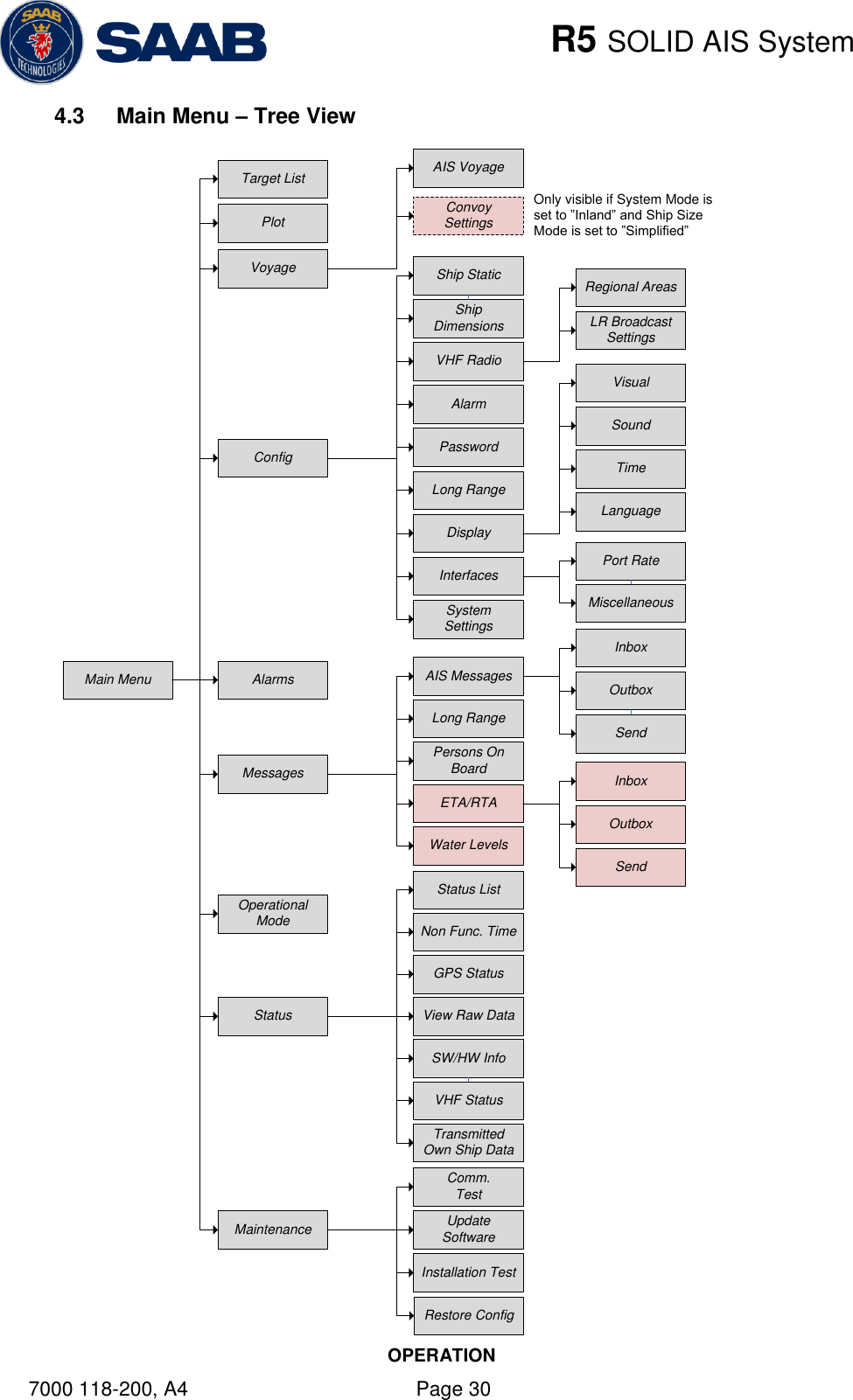

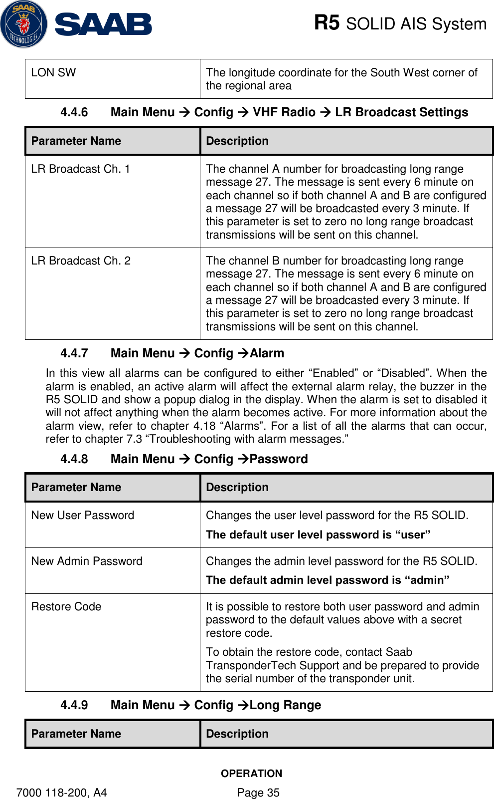
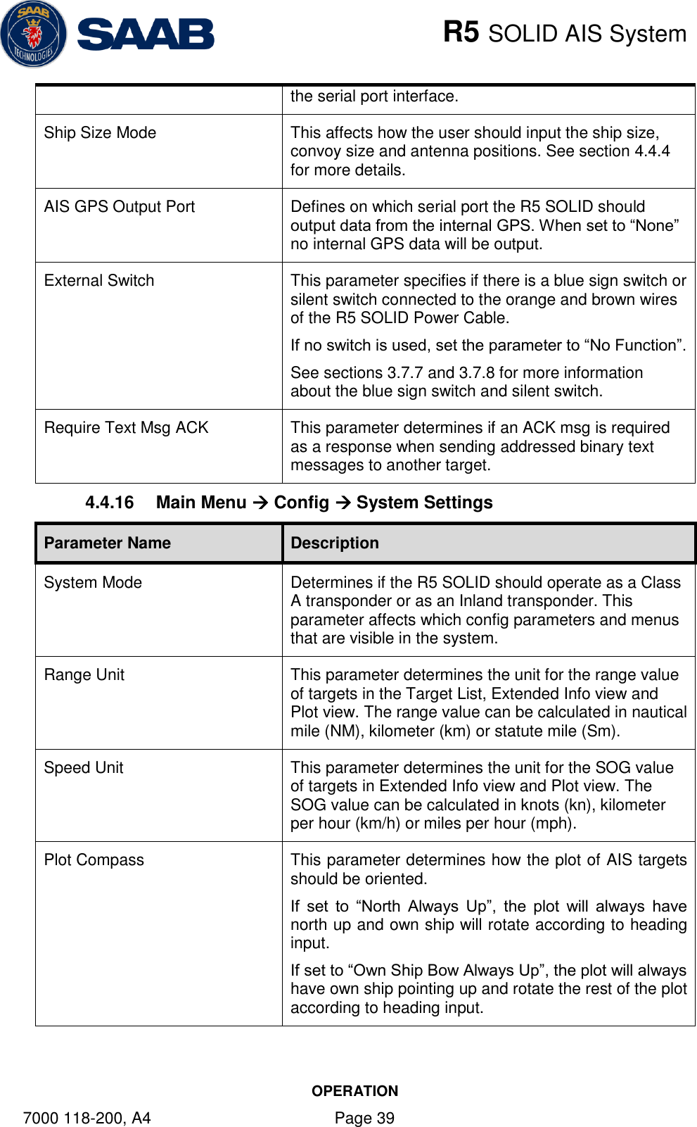
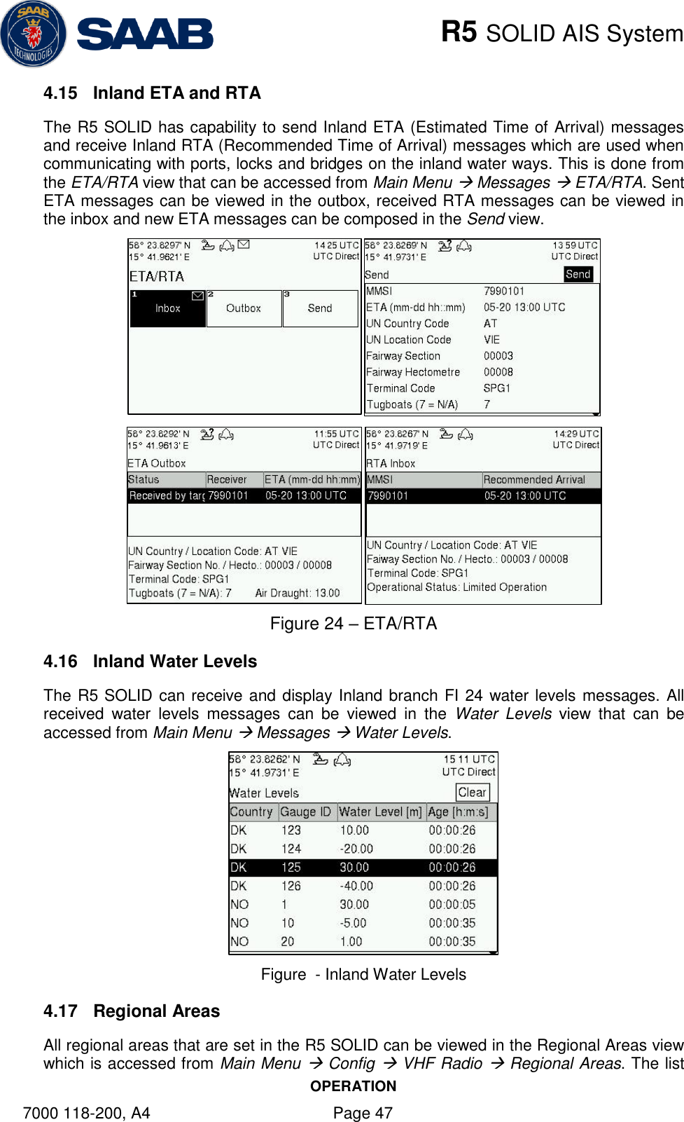
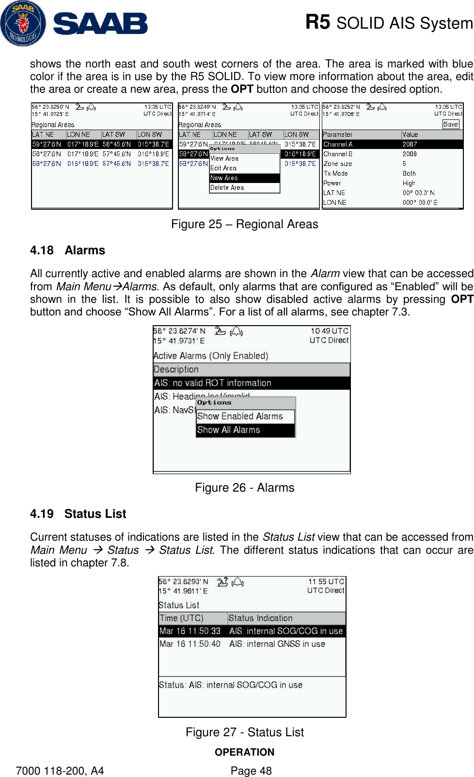
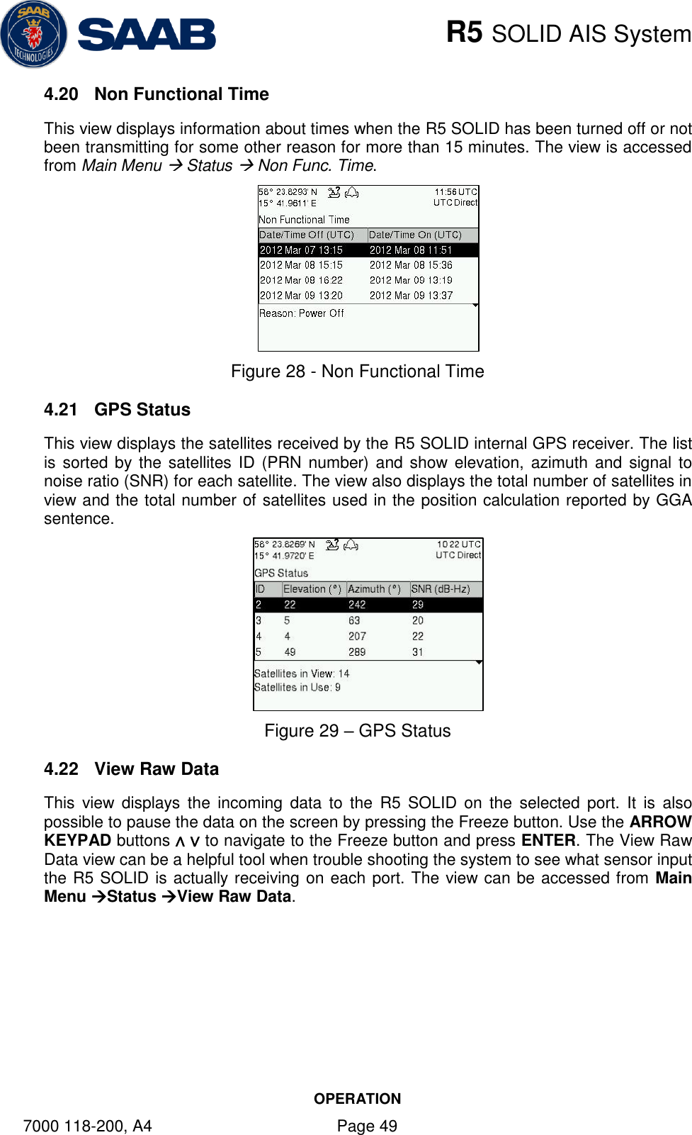
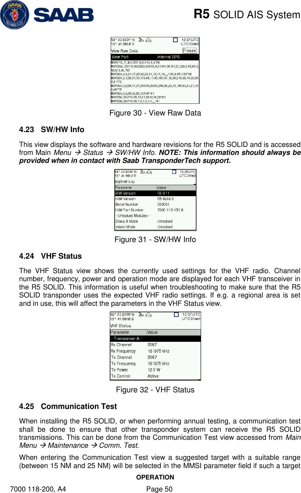
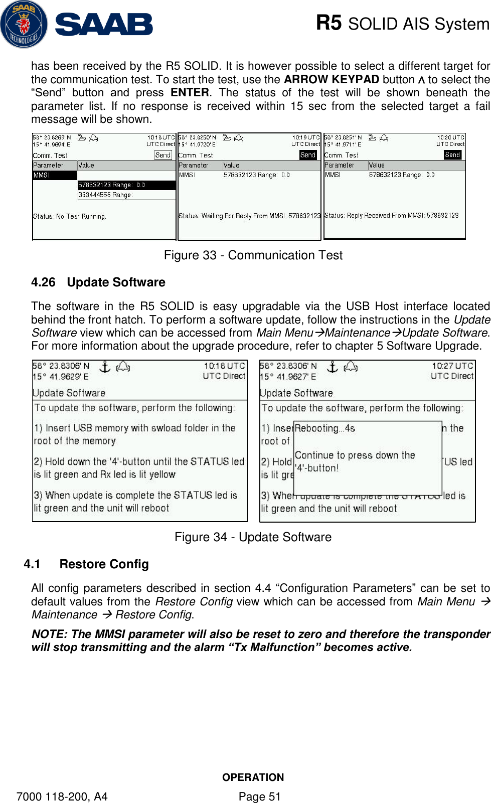
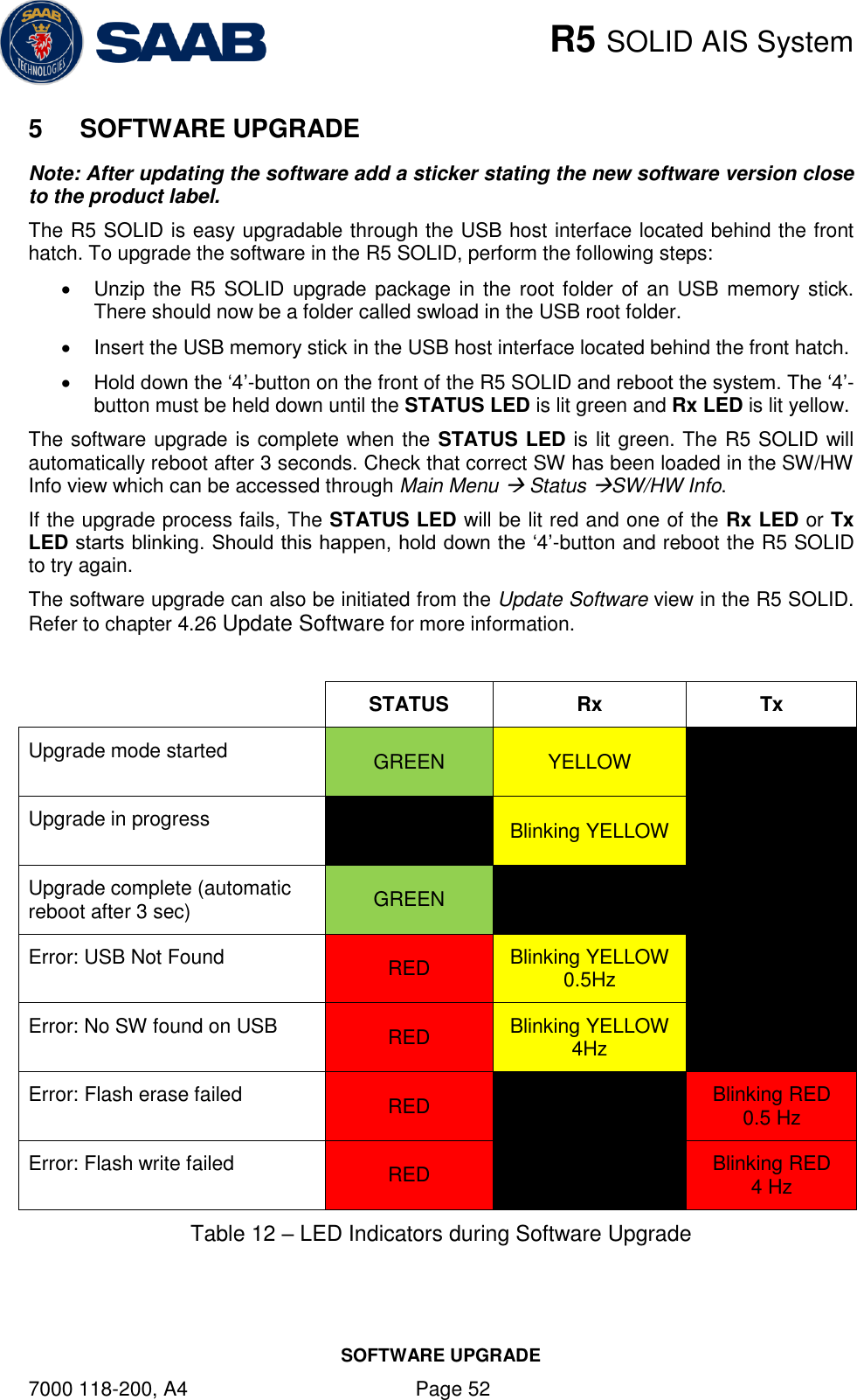
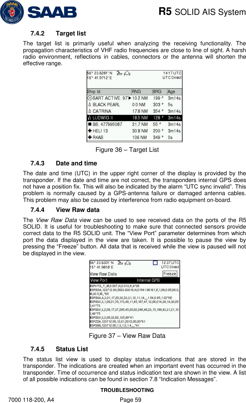
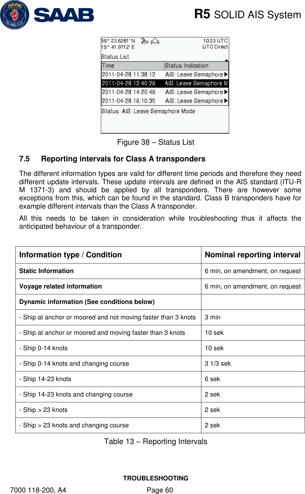
![R5 SOLID AIS System OPERATION 7000 118-200, A4 Page 33 Ship Type (IMO) Type of Ship according to ITU 1371-3. Both numerical input and selection in drop list is possible. Euro Number Unique European Vessel Identification Number reported by own ship Euro Type Ship or combination type according to numeric ERI classification Quality Speed Shall be set to low if no type approved speed sensor is connected to transponder Quality Course Shall be set to low if no type approved course sensor is connected to transponder Quality HDG Shall be set to low if no type approved heading sensor is connected to transponder 4.4.4 Main Menu Config Ship Dimensions The parameters in the Ship Dimensions view depends on the configuration parameter “Ship Size Mode” in the Misc Interfaces view. The Ship Size Mode parameter can be set to either Standard or Simplified (default). The Ship Size Mode affects how the user should input ship size and antenna position information and how it is interpreted. Standard Mode In this mode the user must input: Convoy/ship length [m] (one decimal precision) Convoy/ship beam [m] (one decimal precision) A, B, C, D for internal antenna [m] A, B, C, D for external antenna [m] It is the users responsibility to input correctly rounded data (A+B = Convoy/ship length rounded up, C+D = Convoy/ship beam rounded up). If the user inputs data which is not correctly rounded the “Ship size mismatch” alarm will be activated. The output on the AIS data link will be exactly the values input by the user. Simplified Mode (default) In this mode the user inputs: Ship length [m] (one decimal precision) Ship beam [m] (one decimal precision) X, Y for internal antenna relative to ship [m] (one decimal precision) X, Y for external antenna relative to ship [m] (one decimal precision) When operating in Inland Mode, extra convoy size can be added to ship dimension](https://usermanual.wiki/Saab-TransponderTech/R5-AIS.manual/User-Guide-1791683-Page-33.png)
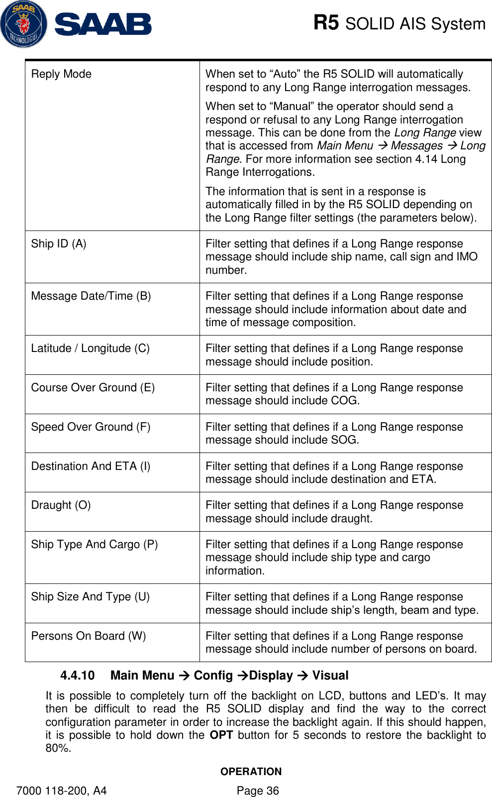
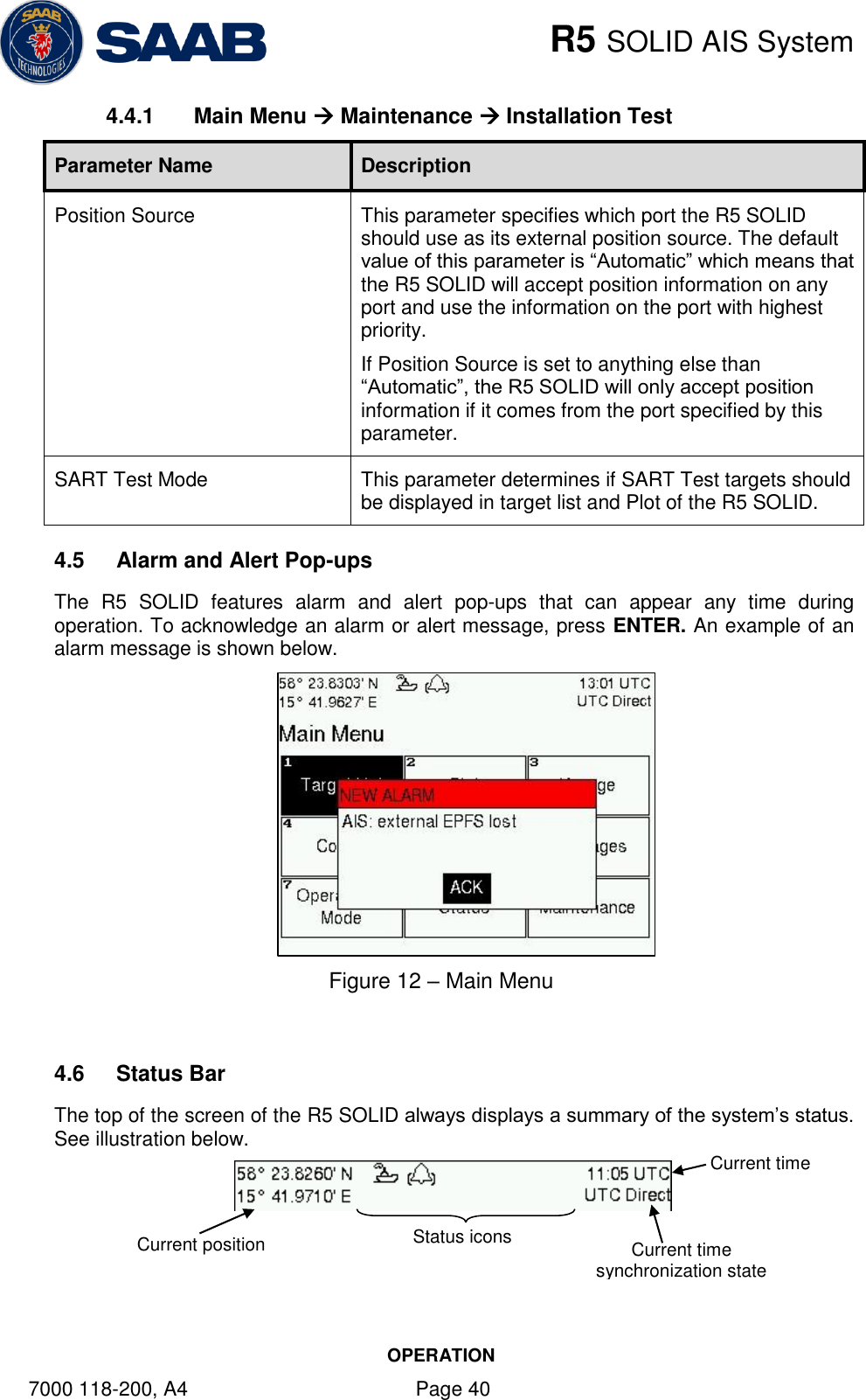
![R5 SOLID AIS System OPERATION 7000 118-200, A4 Page 34 Extra convoy size on each side (value = 0 if convoy not used): Bow [m] (one decimal precision) Stern [m] (one decimal precision) Port side [m] (one decimal precision) Starboard [m] (one decimal precision) The extra convoy parameters can be configured from Main MenuVoyageConvoy Settings when the Ship Size Mode is set to “Simplified”. In this mode there is no way for the user to input mismatching data, all parameters uses the same precision and each measurement is entered only once (in standard mode it is for example possible to enter three different lengths of ship: Convoy/ship length, internal A+B and external A+B). In simplified mode the transponder will automatically calculate and correctly round the A, B, C and D values reported on the VHF link. 4.4.5 Main Menu Config VHF Radio Regional Areas This view shows the regional areas set in the transponder. To make a new regional area or to edit or delete an existing regional area, press the OPT button and choose the desired action. The following parameters can be edited when “New Area” or “Edit Area” is chosen: Parameter Name Description Channel A The channel number for AIS channel A (2087 = default) that should be used in the regional area. Channel B The channel number for AIS channel B (2088 = default) that should be used in the regional area. Zone Size The transitional zone size of the regional area in nautical miles (NM). Tx Mode Decides which channels the transponder will use when transmitting in the regional area. When set to “None”, the transponder will stop automatic transmissions on AIS channels A and B but it will still answer when interrogated on the DSC channel. Power Transmission effect for the transponder in the regional area. High = 12,5 W, Low = 1 W. LAT NE The latitude coordinate for the North East corner of the regional area LON NE The longitude coordinate for the North East corner of the regional area LAT SW The latitude coordinate for the South West corner of the regional area](https://usermanual.wiki/Saab-TransponderTech/R5-AIS.manual/User-Guide-1791683-Page-34.png)