Safety Technology 34151 Battery-Powered Driveway Monitor User Manual
Safety Technology International, Inc. Battery-Powered Driveway Monitor
User manual
— 1 —
— 2 — — 3 —
Safety Technology International, Inc.
2306 Airport Rd • Waterford, MI 48327
Phone: 248-673-9898 • Fax: 248-673-1246
info@sti-usa.com • www.sti-usa.com
Safety Technology International (Europe) Ltd.
Unit 49G Pipers Road • Park Farm Industrial Estate • Redditch
Worcestershire • B98 0HU • England • Tel: 44 (0) 1527 520 999
Fax: 44 (0) 1527 501 999 • Freephone: 0800 085 1678 (UK only)
info@sti-europe.com • www.sti-europe.com
Inst. Sht. WirelessDriveway APRIL2010
Installation and Operation Manual
STI Wireless Driveway MonitorTM
Thank you for purchasing this ne product. We want you to know your satisfaction is very
important to us. We suggest you take the time to read this manual carefully to get the most
from your new product.
HOW THE PRODUCT WORKS
Because of its patented magnetometer SENSOR system, the Driveway Monitor will only
be triggered by cars or trucks - not people, animals and so forth. When a vehicle passes
the Motion Alert® SENSOR next to the driveway, the RECEIVER unit inside the ofce or
home sounds a chime and ashes the alert light. The alert light will continue to ash until
reset and the RECEIVER will continue to chime each time a vehicle passes. The earth has
a uniform magnetic eld around it. A vehicle creates a slight disturbance in the earth’s eld.
The SENSOR detects this disturbance and transmits a signal to the RECEIVER.
BEFORE YOU START
Refer to this drawing to become familiar with all the parts.
STI-30104
LAMP CONTROLLER
(OPTIONAL)
AC ADAPTER
GREEN
LED
75 mA
OUTPUT
RECEIVER ANTENNA
SPEAKER
STI-34104
INDOOR RECEIVER
BUTTON
RED LED
TRANSMITTER CAP
BATTERY / CIRCUIT
BOARD HOLDER
TRANSMITTER BASE
MOUNTING
TUBE CAP
WALL MOUNT
2 “C” BATTERIES
TRANSMITTER
CIRCUIT BOARD
MOUNTING TUBE
MOUNTING STAKE
TRANSMITTER CAP
TRANSMITTER
MOUNTING
TUBE CAP
MOUNTING TUBE
MOUNTING STAKE
WALL MOUNT
TRANSMITTER CAP
SCREWS
RECHARGEABLE
NiMH BATTERIES
HL
SENSITIVITY JUMPERS
(SOLAR TYPE)
SENSITIVITY JUMPERS
(BATTERY TYPE)
H
L
FINGER
NOTCHES
REMOVE PLASTIC TAB
FROM BATTERIES
DRIVEWAY
3’OR
LESS
25' OR MORE
PLACE SENSOR 3' OR
LESS FROM EDGE OF
DRIVEWAY AND 25' OR
MORE FROM STREET.
12’
MAX
DRIVEWAY
PLACE SENSOR
3' OR LESS FROM
EDGE OF DRIVEWAY
AND 25+ FEET OR
MORE FROM STREET.
25' OR MORE
3' OR
LESS
12'
MAX
+
+
-
B
DETAIL B
SCALE 2:1
B
C
HL
-
+
+
-
B
-
BATTERY POWERED SENSOR SOLAR POWERED SENSOR
STI-34150 Battery Power Kit
STI-34100 Solar Power Kit
STI-30104
LAMP CONTROLLER
(OPTIONAL)
AC ADAPTER
GREEN
LED
75 mA
OUTPUT
RECEIVER ANTENNA
SPEAKER
STI-34104
INDOOR RECEIVER
BUTTON
RED LED
TRANSMITTER CAP
BATTERY / CIRCUIT
BOARD HOLDER
TRANSMITTER BASE
MOUNTING
TUBE CAP
WALL MOUNT
2 “C” BATTERIES
TRANSMITTER
CIRCUIT BOARD
MOUNTING TUBE
MOUNTING STAKE
TRANSMITTER CAP
TRANSMITTER
MOUNTING
TUBE CAP
MOUNTING TUBE
MOUNTING STAKE
WALL MOUNT
TRANSMITTER CAP
SCREWS
RECHARGEABLE
NiMH BATTERIES
HL
SENSITIVITY JUMPERS
(SOLAR TYPE)
SENSITIVITY JUMPERS
(BATTERY TYPE)
H
L
FINGER
NOTCHES
REMOVE PLASTIC TAB
FROM BATTERIES
DRIVEWAY
3’OR
LESS
25' OR MORE
PLACE SENSOR 3' OR
LESS FROM EDGE OF
DRIVEWAY AND 25' OR
MORE FROM STREET.
12’
MAX
DRIVEWAY
PLACE SENSOR
3' OR LESS FROM
EDGE OF DRIVEWAY
AND 25+ FEET OR
MORE FROM STREET.
25' OR MORE
3' OR
LESS
12'
MAX
+
+
-
B
DETAIL B
SCALE 2:1
B
C
HL
-
+
+
-
B
-
INDOOR RECEIVER STI-34104
(Receives up to 4 different STI sensors)
Install batteries into the TRANSMITTER
1. Remove the TRANSMITTER cap by turning it counterclockwise.
2. WITHOUT PULLING ON THE BRASS ANTENNA OR ANY
WIRES, grasp the outside of the battery/circuit board holder
by the nger notches, twist gently and pull out. Insert two “C”
alkaline batteries (not included).
3. Replace the battery/circuit board holder and TRANSMITTER
cap.
4. Place the TRANSMITTER on a table or counter approximately
5-10 ft. away from you. TRANSMITTER may make a faint
clicking noise - this is normal.
STI-30104
LAMP CONTROLLER
(OPTIONAL)
AC ADAPTER
GREEN
LED
75 mA
OUTPUT
RECEIVER ANTENNA
SPEAKER
STI-34104
INDOOR RECEIVER
BUTTON
RED LED
TRANSMITTER CAP
BATTERY / CIRCUIT
BOARD HOLDER
TRANSMITTER BASE
MOUNTING
TUBE CAP
WALL MOUNT
2 “C” BATTERIES
TRANSMITTER
CIRCUIT BOARD
MOUNTING TUBE
MOUNTING STAKE
TRANSMITTER CAP
TRANSMITTER
MOUNTING
TUBE CAP
MOUNTING TUBE
MOUNTING STAKE
WALL MOUNT
TRANSMITTER CAP
SCREWS
RECHARGEABLE
NiMH BATTERIES
HL
SENSITIVITY JUMPERS
(SOLAR TYPE)
SENSITIVITY JUMPERS
(BATTERY TYPE)
H
L
FINGER
NOTCHES
REMOVE PLASTIC TAB
FROM BATTERIES
DRIVEWAY
3’OR
LESS
25' OR MORE
PLACE SENSOR 3' OR
LESS FROM EDGE OF
DRIVEWAY AND 25' OR
MORE FROM STREET.
12’
MAX
DRIVEWAY
PLACE SENSOR
3' OR LESS FROM
EDGE OF DRIVEWAY
AND 25+ FEET OR
MORE FROM STREET.
25' OR MORE
3' OR
LESS
12'
MAX
+
+
-
B
DETAIL B
SCALE 2:1
B
C
HL
-
+
+
-
B
-
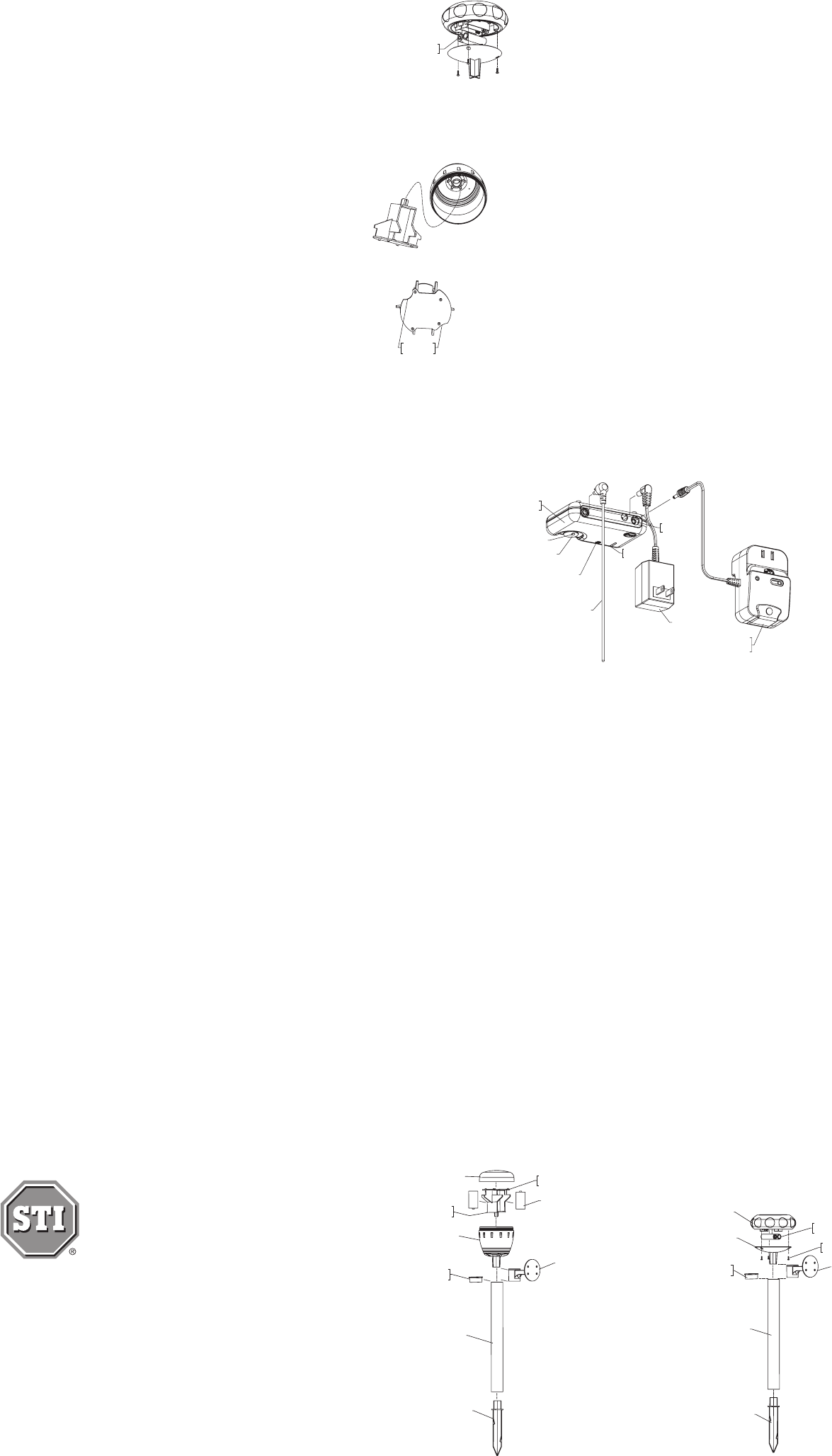
1. Remove the bottom of the TRANSMITTER by removing the 3
screws on the bottom of the unit.
2. Remove the plastic tab between the batteries.
3. Replace the bottom of the unit and tighten down with the 3
screws.
4. Place the TRANSMITTER in direct sunlight for 48 hours
OR place batteries in a NiMH (nickel metal hydride) battery
charger.
SOLAR POWERED:
BATTERY POWERED:
STI-30104
LAMP CONTROLLER
(OPTIONAL)
AC ADAPTER
GREEN
LED
75 mA
OUTPUT
RECEIVER ANTENNA
SPEAKER
STI-34104
INDOOR RECEIVER
BUTTON
RED LED
TRANSMITTER CAP
BATTERY / CIRCUIT
BOARD HOLDER
TRANSMITTER BASE
MOUNTING
TUBE CAP
WALL MOUNT
2 “C” BATTERIES
TRANSMITTER
CIRCUIT BOARD
MOUNTING TUBE
MOUNTING STAKE
TRANSMITTER CAP
TRANSMITTER
MOUNTING
TUBE CAP
MOUNTING TUBE
MOUNTING STAKE
WALL MOUNT
TRANSMITTER CAP
SCREWS
RECHARGEABLE
NiMH BATTERIES
HL
SENSITIVITY JUMPERS
(SOLAR TYPE)
SENSITIVITY JUMPERS
(BATTERY TYPE)
H
L
FINGER
NOTCHES
REMOVE PLASTIC TAB
FROM BATTERIES
DRIVEWAY
3’OR
LESS
25' OR MORE
PLACE SENSOR 3' OR
LESS FROM EDGE OF
DRIVEWAY AND 25' OR
MORE FROM STREET.
12’
MAX
DRIVEWAY
PLACE SENSOR
3' OR LESS FROM
EDGE OF DRIVEWAY
AND 25+ FEET OR
MORE FROM STREET.
25' OR MORE
3' OR
LESS
12'
MAX
+
+
-
B
DETAIL B
SCALE 2:1
B
C
HL
-
+
+
-
B
-
Set up the RECEIVER and program the TRANSMITTER:
1. Plug the antenna into the back of the RECEIVER.
2. Plug the AC adapter into the back of the RECEIVER and into the wall outlet.
3. RECEIVER will make a start up tone and the green LED will ash.
4. Push and hold the button on the RECEIVER until you hear a second beep (approximately
3 seconds) then let go of the button.
5. Red LED will be solid YOU NOW HAVE 60 SECONDS TO COMPLETE PROGRAMMING.
6. Pick up the TRANSMITTER and rotate it until the green LED on the RECEIVER ashes
and the RECEIVER makes a short tone. (If you have an additional TRANSMITTER(s),
repeat this step while RECEIVER is still in Programming Mode.)
7. Place TRANSMITTER onto counter or table.
8. Press and release the button on the RECEIVER (red LED should now be off).
9. Rotate the TRANSMITTER again until the green LED ashes and the RECEIVER makes
the alert tone.
CONGRATULATIONS! You are now ready to install the TRANSMITTER. If for any reason
your RECEIVER does not respond correctly to above steps please see “Clearing the
RECEIVER.” Follow those steps and return to “Set up the RECEIVER and program the
TRANSMITTER” above. Or, call STI Support at 800-888-4784.
Install the TRANSMITTER:
The Solar unit must be placed in an area that receives partial or full sunlight. For both
models, be sure the location of the TRANSMITTER is at least 25’ back from the main road.
For a typical 12’ wide driveway, it is recommended the TRANSMITTER be no more than
3’ away from the driveway (see drawing). Additional TRANSMITTERS may be required
for driveways exceeding 12’. TRANSMITTER may be placed up to 1,000 feet away from
RECEIVER; however, range may vary depending upon environment and use of wireless
telephones, wireless routers and other similar devices.

STI-30104
LAMP CONTROLLER
(OPTIONAL)
AC ADAPTER
GREEN
LED
75 mA
OUTPUT
RECEIVER ANTENNA
SPEAKER
STI-34104
INDOOR RECEIVER
BUTTON
RED LED
TRANSMITTER CAP
BATTERY / CIRCUIT
BOARD HOLDER
TRANSMITTER BASE
MOUNTING
TUBE CAP
WALL MOUNT
2 “C” BATTERIES
TRANSMITTER
CIRCUIT BOARD
MOUNTING TUBE
MOUNTING STAKE
TRANSMITTER CAP
TRANSMITTER
MOUNTING
TUBE CAP
MOUNTING TUBE
MOUNTING STAKE
WALL MOUNT
TRANSMITTER CAP
SCREWS
RECHARGEABLE
NiMH BATTERIES
HL
SENSITIVITY JUMPERS
(SOLAR TYPE)
SENSITIVITY JUMPERS
(BATTERY TYPE)
H
L
FINGER
NOTCHES
REMOVE PLASTIC TAB
FROM BATTERIES
DRIVEWAY
3’OR
LESS
25' OR MORE
PLACE SENSOR 3' OR
LESS FROM EDGE OF
DRIVEWAY AND 25' OR
MORE FROM STREET.
12’
MAX
DRIVEWAY
PLACE SENSOR
3' OR LESS FROM
EDGE OF DRIVEWAY
AND 25+ FEET OR
MORE FROM STREET.
25' OR MORE
3' OR
LESS
12'
MAX
+
+
-
B
DETAIL B
SCALE 2:1
B
C
HL
-
+
+
-
B
-
— 6 — — 7 —
— 4 — — 5 —
STI-30104
LAMP CONTROLLER
(OPTIONAL)
AC ADAPTER
GREEN
LED
75 mA
OUTPUT
RECEIVER ANTENNA
SPEAKER
STI-34104
INDOOR RECEIVER
BUTTON
RED LED
TRANSMITTER CAP
BATTERY / CIRCUIT
BOARD HOLDER
TRANSMITTER BASE
MOUNTING
TUBE CAP
WALL MOUNT
2 “C” BATTERIES
TRANSMITTER
CIRCUIT BOARD
MOUNTING TUBE
MOUNTING STAKE
TRANSMITTER CAP
TRANSMITTER
MOUNTING
TUBE CAP
MOUNTING TUBE
MOUNTING STAKE
WALL MOUNT
TRANSMITTER CAP
SCREWS
RECHARGEABLE
NiMH BATTERIES
HL
SENSITIVITY JUMPERS
(SOLAR TYPE)
SENSITIVITY JUMPERS
(BATTERY TYPE)
H
L
FINGER
NOTCHES
REMOVE PLASTIC TAB
FROM BATTERIES
DRIVEWAY
3’OR
LESS
25' OR MORE
PLACE SENSOR 3' OR
LESS FROM EDGE OF
DRIVEWAY AND 25' OR
MORE FROM STREET.
12’
MAX
DRIVEWAY
PLACE SENSOR
3' OR LESS FROM
EDGE OF DRIVEWAY
AND 25+ FEET OR
MORE FROM STREET.
25' OR MORE
3' OR
LESS
12'
MAX
+
+
-
B
DETAIL B
SCALE 2:1
B
C
HL
-
+
+
-
B
-
1. Insert cap to tube.
2. Insert stake to opposite end of tube.
3. Place the tube (stake side down) into the ground within 3’ of the driveway
and more than 25’ from the road.
4. Gently hammer the cap side of the tube until stake is rmly in the ground.
5. Remove cap and place TRANSMITTER on tube.
6. The TRANSMITTER should have a clear line-of-site to the
RECEIVER to improve performance. For the solar model,
rotate the TRANSMITTER so the antenna has a clear line-
of-site to the RECEIVER. NOTE: If the battery has been
weak or out of range for 12-24 hours, the RECEIVER will
annunciate once per minute until the TRANSMITTER is
detected or cleared from memory.
7. Place the TRANSMITTER so the vehicle does not pass between it and the RECEIVER.
To obtain optimal range:
STI recommends the use of the stake and tube included with your Driveway Monitor.
However, if you choose to mount the unit to an alternate mounting device, please be sure
the device is stable. STI does not recommend mounting the TRANSMITTER to a tree or
a metal fence or gate.
Sensitivity Adjustment:
The factory default setting (HIGH) may be adjusted by changing the jumper position inside the
TRANSMITTER.
For SOLAR POWERED
1. Remove the bottom of the TRANSMITTER by removing the 3 screws
on the bottom of the unit.
2. Position the jumper to desired sensitivity (as shown above).
• LOW: Position jumper on the two leftmost pegs.
• MEDIUM: Completely remove jumper.
• HIGH: Position jumper on the two rightmost pegs.
3. Replace the bottom of the unit and tighten down with the 3 screws.
For BATTERY POWERED
1. Unscrew cap.
2. Position the jumper to desired sensitivity (as shown).
• LOW: Position jumper on the two leftmost pegs.
• MEDIUM: Completely remove jumper.
• HIGH: Position jumper on the two rightmost pegs.
3. Replace cap.
L H
Low
Medium
High
Modes of operation (for both Battery and Solar Models):
Normal Operating mode
The green LED may ash periodically to indicate routine signals are being received. This
does not mean a vehicle is approaching. When a vehicle is detected, a short alert tone
will play* and the red LED on the RECEIVER will ash until reset. The TRANSMITTER has a
10-15 second delay before the next vehicle will be detected. To reset the RECEIVER, press
and release the button.
*Note: If more than one TRANSMITTER is being used and is triggered, the RECEIVER will
beep twice, three times, etc., before playing the alert tone to indicate which TRANSMITTER
was detected.
Temporary (8 Hours) and Permanent Silent Modes
These modes may be entered ONLY while the RECEIVER is in Normal Operating Mode. If
there is a power outage, the RECEIVER will stay in that Silent Mode until reset.
Entering Temporary Silent Mode - Press and hold the button on the RECEIVER until you
hear a second beep (approximately 3 seconds). Red LED will be on solid.
Entering Permanent Silent Mode - Press and hold the button until the RECEIVER makes
a series of two short beeps (approximately 6 seconds). Red LED will be on solid.
In either Silent Mode, the red LED will change from continuous to ashing when a
transmission is detected by the RECEIVER.
To Return to Normal Operating Mode
1. Push and hold the button until you hear a single beep.
Clearing the RECEIVER (for both Battery and Solar Models):
These steps will completely clear the RECEIVER of all programming.
1. Disconnect power from RECEIVER and wait for 15 seconds.
2. Reconnect the power to the RECEIVER.
3. Press and hold the button until you hear two short beeps.
4. Red LED will be solid.
5. Press and release the button.
6. Disconnect power from RECEIVER and wait another 15 seconds.
To reprogram the RECEIVER, follow the steps in “Set up the RECEIVER and program the
TRANSMITTER.”
Transistor Output Jack (all models):
This output can trigger the Lamp Controller (STI-30104) or another low powered device
such as a relay. The output is a 3.5mm mono jack and is polarity sensitive. Output will
supply 75mA at 12VDC for three seconds.
Low Battery / Out of Range TRANSMITTER:
If the battery is too weak or out of range between 12 - 24 hours, the RECEIVER will annunciate
once per minute with a number of beeps to indicate the TRANSMITTER with the trouble
(i.e. 1 beep for the rst, 2 beeps for the second, etc.). If in silent mode the RECEIVER will
return to normal mode to annunciate. This will continue until the TRANSMITTER is detected
or cleared from memory.
TROUBLE SOLUTION
1. Check that the AC power outlet has power.
2. Check that the AC Adapter is plugged in to both the RE-
CEIVER and wall outlet.
3. Try another AC adapter (12V DC 100mA only) with a +12
VDC center and -12 VDC outside edge.
The RECEIVER does not
power up (green LED is off).
1. Check that the RECEIVER is not in Temporary or
Permanent Silent Mode.
2. Check the TRANSMITTER by picking it up and rotating it.
The TRANSMITTER should make a “cricket” noise.
3. Check that the TRANSMITTER and RECEIVER are within
operating distance from each other.
4. Check the TRANSMITTER batteries and replace if
necessary. Reprogram the RECEIVER using the steps in
“Clearing the RECEIVER” and “Set up the RECEIVER and
program the TRANSMITTER.”
5. For Solar model only, make sure the TRANSMITTER is in
direct sunlight and that it has been charging for at least
48 hours. Replace batteries if necessary. Use only AA
(1.2v) NiMH rechargeable batteries. Charge the sensor
in direct sunlight for 48 hours. Reprogram the RECEIVER
using the steps in “Clearing the RECEIVER” and “Set up
the RECEIVER and program the TRANSMITTER.”
The RECEIVER does not
sound when a vehicle
passes by.
1. Check that the TRANSMITTER and RECEIVER are within
operating distance from each other.
2. Change the Sensitivity in the TRANSMITTER using the
steps in “Sensitivity Adjustment.”
3. Check that the TRANSMITTER and RECEIVER are located
so a vehicle does not pass between them.
4. Change the location of the TRANSMITTER by placing it
closer to the edge of the driveway.
5. Bring the TRANSMITTER close enough to the RECEIVER
so the RECEIVER button is visible. Test the TRANSMITTER
by passing a steel shovel or large magnet around the
TRANSMITTER. The TRANSMITTER should make a
“cricket” noise and the red LED on the RECEIVER should
ash.
6. Check the TRANSMITTER batteries and replace if
necessary.
7. Reprogram the RECEIVER using the steps in “Clearing the
RECEIVER” and “Set up the RECEIVER and program the
TRANSMITTER.”
The TRANSMITTER does
not activate when a car
passes by.
1. Is the TRANSMITTER mounted rmly and not effected by
wind?
2. Is the TRANSMITTER at least 25’ away from the main
road?
3. Be sure there are no other metal objects near the
TRANSMITTER that may move.
4. Reprogram the RECEIVER using the steps in “Clearing the
RECEIVER” and “Set up the RECEIVER and program the
TRANSMITTER.”
The RECEIVER sounds
when there is no vehicle
passing by.
1. This may occur in severe weather.
The RECEIVER sounds
when lightning strikes.
IMPORTANT NOTICE:
This product has been tested and complies with the specications for a Class B digital device,
pursuant to Part 15 of the FCC Rules. These limits are designed to provide reasonable
protection against harmful interference in a residential installation. This equipment generates,
uses, and can radiate radio frequency energy and, if not installed and used according to
the instructions, may cause harmful interference to radio communications. However, there
is no guarantee that interference will not occur in a particular installation. If this equipment
does cause harmful interference to radio or television reception, which is found by turning
the equipment off and on, the user is encouraged to try to correct the interference by one
or more of the following measures:
• Reorient or relocate the receiving antenna
• Increase the separation between the equipment or devices
• Connect the equipment to an outlet other than the receiver’s
• Consult a dealer or an experienced radio/TV technician for assistance
Operation is subject to the following two conditions: (1) this device may not cause
interference, and (2) this device must accept any interference, including interference that
may cause undesired operation of the device. Changes or modications not expressly
approved by Safety Technology International, Inc. could void your authority to operate this
equipment.
To reduce potential radio interference to other users, the antenna type and its gain should
be so chosen that the equivalent isotropically radiated power (e.i.r.p.) is not more than that
permitted for successful communication.
OPTIONAL LAMP CONTROLLER ACCESSORY
The lamp controller will turn on a lamp any time your DRIVEWAY MONITORTM is triggered.
Never come home to a dark house again, and let others think you are home when you
aren’t. The Lamp Controller works with both the STI-34150 (battery) and the STI-34100
(solar) models.
WARNINGS
FOR INDOOR USE ONLY. This unit CANNOT be used with 3-prong grounded plugs.
Do not connect RECEIVER to any heat producing device. Keep RECEIVER away
from water and/or damp areas. To prevent electric shock, match wide blade of
plug to the wide slot of outlet and insert completely.
When using lamp controller option, use ONLY 200 Watt or less incandescent lamp,
and keep lamp away from bed coverings, curtains or other ammable materials as
this may present a re hazard.
WARRANTY INFORMATION:
Safety Technology International, Inc. warrants to the original consumer/purchaser that
this product shall be free of defects in material and workmanship under normal use and
circumstances for a period of one (1) year from the original date of purchase.
Model 34104 Model 34101 Model 34151
FCC ID: TXL34104 FCC ID: TXL34101 FCC ID: TXL34151
IC ID: 6550A-34104 IC ID: 6550A-34101 IC ID: 6550A-34151
Optional accessories
STI-34101 Additional Solar Powered TRANSMITTER
STI-34104 Additional RECEIVER
STI-30104 Lamp Controller
STI-34151 Additional Battery Powered TRANSMITTER