Sagem Wireless MA220 MA220 User Manual
Sagem Wireless MA220 Users Manual
Users Manual
1

2
3
2
3
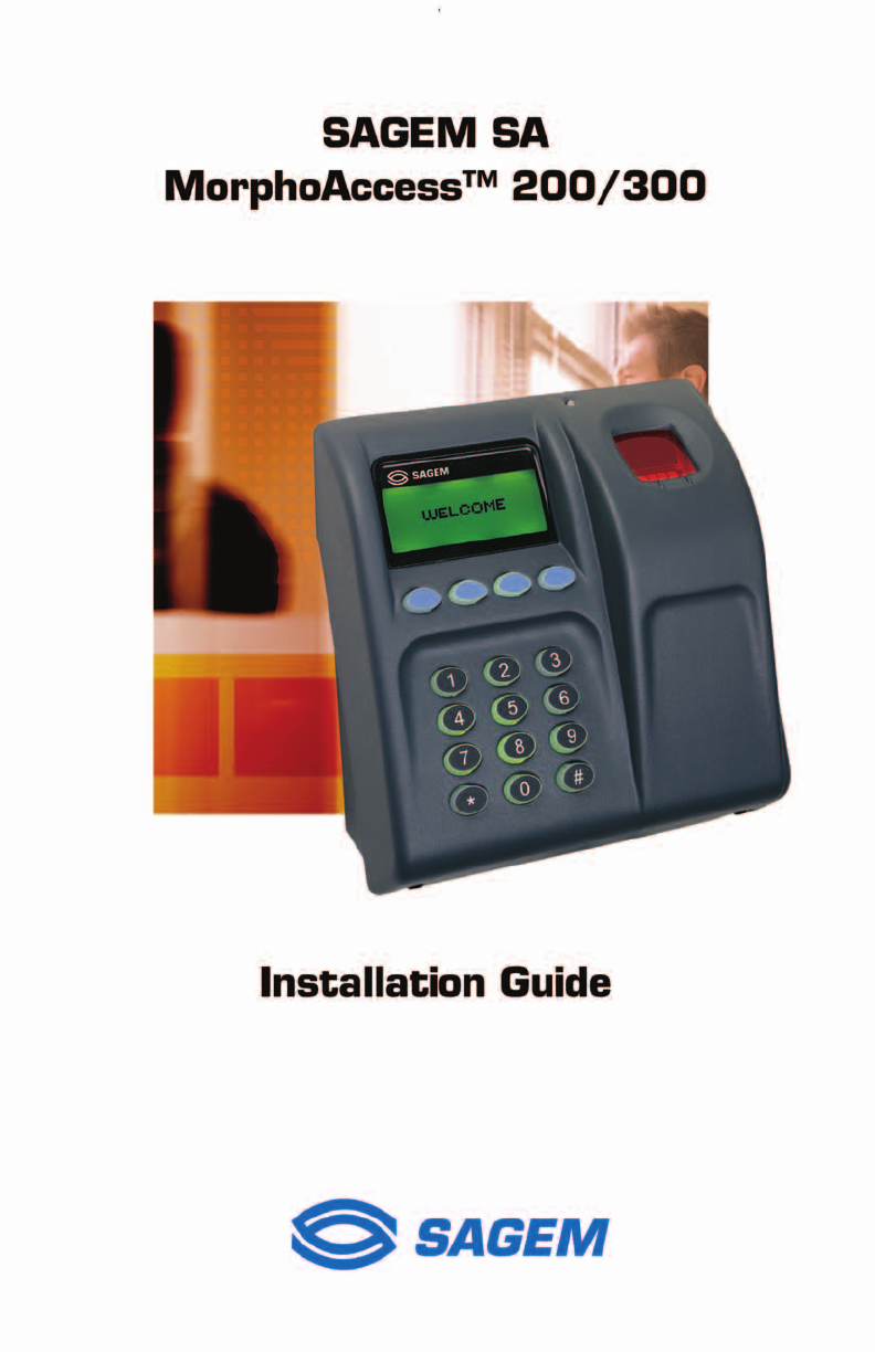
MorphoAccess TM 200/300
Installation Guide
SAGEM MORPHO, Inc.
1145 Broadway Plaza, Suite 200
Tacoma, WA. 98402
i
CONTENTS
Welcome to MorphoAccess™ 1
Safety instructions 2
General description 4
Installation procedure 5
Stage 1: Drilling the mounting holes for the metal chassis assembly 5
Stage 2: Mounting the metal chassis assembly 6
Stage 3: Connecting the chassis assembly to the cover assembly 7
Stage 4: Closing MorphoAccess™ 8
How to upgrade MorphoAccess™ 200 to 300 9
Electrical interfaces 10
Terminal block board 10
Power supply cable 11
COM1 RS485/422 serial port wiring 11
COM1 Deister wiring (optional) 12
Ethernet wiring 12
COM2 RS232 wiring 13
COM2 RS422 wiring 14
Wiegand output wiring 14
Wiegand input wiring 15
Data clock output wiring 15
Data clock input wiring 16
Input / output wiring (optional) 17
Output relays and Tamper switch 18
Conguring the MorphoAccessTM 19
Motherboard conguration 19
Optional communications cable 20
MorphoAccess™ Technical characteristics 21
Display 21
Keyboard 21
Fuse 21
Memory 21
Peripherals interfaces 21
Contents
ii
1
Power supply 22
Size and weight 22
Environmental conditions 22
Storage conditions 22
Recommendations 23
Areas containing combustibles 23
General precautions 23
Appendix 1 - Ethernet color standard 24
Appendix 2 - Wiegand data format 25
Appendix 3 - ISO 7811/2-1995 - Track 2 Dataclock format 26
Appendix 4 - Reserved conguration keys 28
Appendix 5 - Morpho Product Warranty and End-User Software License 29
Drilling Template 32
Contents
ii
1
Welcome to MorphoAccess™
Congratulations for choosing the MorphoAccess™ Automatic
Fingerprint Recognition Terminal. MorphoAccess™ provides
an innovative and effective solution for access control or time
and attendance applications using ngerprint verication and/or
identication.
Among a range of alternative biometric techniques, the use of
nger imaging has signicant advantages: each nger constitutes
an unalterable physical signature which develops before birth and
is preserved until death. Unlike DNA, a nger image is unique to
each individual - even identical twins.
The MorphoAccess™ terminal integrates SAGEM image
processing and feature matching-algorithms (MorphoSoft™ and
MorphoImaging™). This technology is based on lessons learned
during 18 years of experience in the eld of biometric identication
and the creation of literally millions of individual ngerprint
identication records.
We believe that you will nd the MorphoAccess™ fast, accurate,
easy to use and suitable for physical access control or time and
attendance.
The MorphoAccess™ offers the following features:
- High quality optical scanner
- Supports multiple input/output interfaces used in the physical
access control industry
- Local area network interface for easy interaction with other
host systems
- Compact size for easy installation and integration into your
available ofce space
- Intuitive interface that is easy to use in both setup and
operational modes
- Extensive, exible ash memory for data storage (user data,
biometric templates, etc.)
To ensure the most effective use of your MorphoAccess™, please
read this Installation Guide in full.
The SAGEM logo and trademark are the property of E.
All other trademarks or product names are trademarks or product names of the
respective title holders.
Introduction

2
3
Safety instructions – Please Read Before Installation
WARNING: Installation must be performed by professional
installers
Note: These instructions for the installation of the
MorphoAccess assume the installer is properly qualied as a
professional, and is familiar with applicable industry standards,
local building/zoning codes, and proper installation practices.
Installation should not be attempted by non-professionals.
You are required to use an NEC class II power supply at
12 V ± 5% and 2.5 A minimum.
This product is intended to be installed in accordance with the
NEC Class 2 requirements; or supplied by a listed external
Power Unit marked Class 2, Limited Power source, or LPS and
rated 12 V DC, 2.5 A minimum.
Europe: SAGEM SA hereby declares that the SAGEM SA
MorphoAccess™ has been tested and found compliant with the
below listed standards as required by the EMC Directive 89/336/
EEC: EN55022 (1994) / EN55024 (1998) and by the low voltage
Directive 73/23/EEC amended by 93/68/EEC: EN60950 (2000).
USA: This equipment has been tested and found compliant
with Class B digital device requirements, pursuant to part 15
of the FCC Rules. These requirements are designed to ensure
reasonable protection against harmful RF interference in a
residential installation. This equipment generates, uses and
can radiate radio frequency energy and, if not installed and
used in accordance with the instructions, may interfere with
radio communications. If this equipment interferes with radio or
television reception - which can be determined by disconnecting
and re-connecting the unit - the user is encouraged to try to correct
the interference by one or more of the following measures:
- Reorient or relocate the receiving antenna
- Increase the separation between the equipment and receiver
- Connect the equipment into an outlet on a circuit different from
that to which the receiver is connected
- Consult the dealer or an experienced radio/TV technician for
help
Safety instructions

2
3
CAUTION
DANGER OF EXPLOSION IF BATTERY IS INCORRECTLY REPLACED.
REPLACE ONLY WITH THE SAME OR EQUIVALENT TYPE
RECOMMENDED BY THE MANUFACTURER.
MUST BE DISPOSED OF PROPERLY.
ATTENTION
IL Y A DANGER D’EXPLOSION S’IL Y A REMPLACEMENT
INCORRECT DE LA BATTERIE.
REMPLACER UNIQUEMENT AVEC UNE BATTERIE DU MEME
TYPE OU D’UN TYPE EQUIVALENT RECOMMANDE PAR LE
CONSTRUCTEUR.
ELIMINER DE FAÇON APPROPRIÉE
Safety instructions
4
5
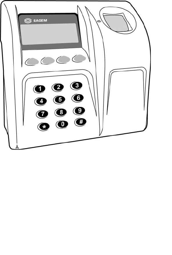
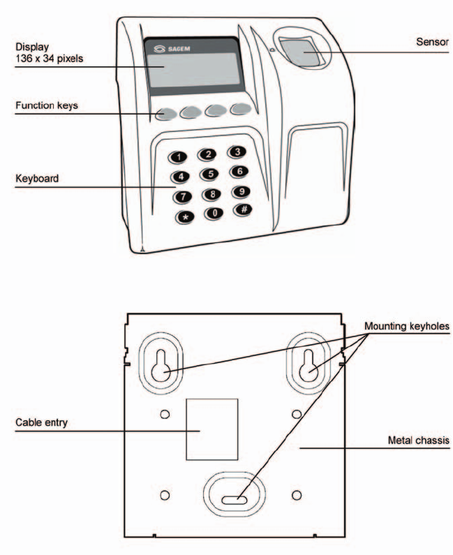
General description
General description
4
5
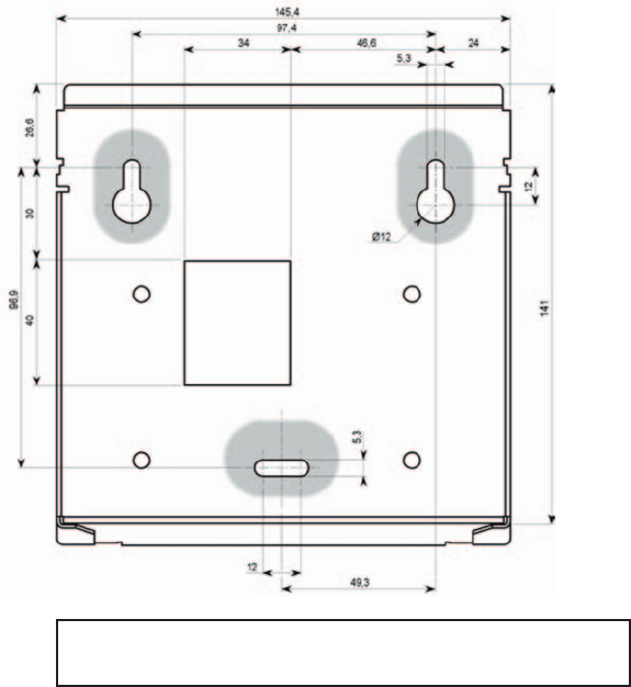
Installation procedure
Stage 1: Drilling the mounting holes for the metal chassis
assembly
Mounting and cable entry hole location (rear view)
Note: The mounting screws can not exceed 5 mm in
diameter.
1) Drill the two holes for the screws for the mounting keyholes so
that the cable entry is in a suitable position for your cabling. Use
the drawing above or (see the Drilling Template section).
2) Drill the hole for the third screw in the center of the slot so that
it is possible to correct the position later, if necessary.
Installation procedure-Stage 1
6
7
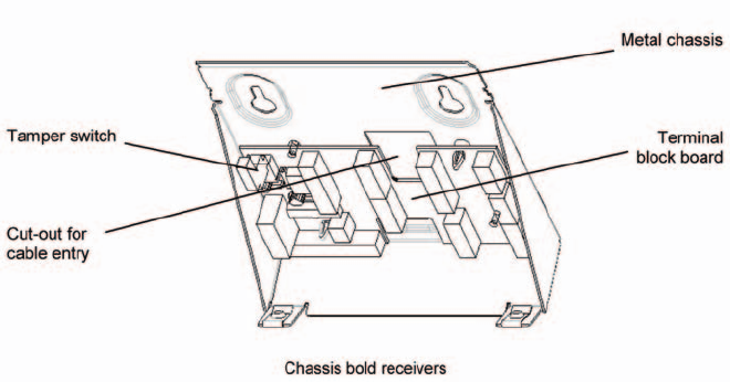
Stage 2: Mounting the metal chassis assembly
Chassis bold receivers
1) Disconnect the ribbon cable between the motherboard and the
terminal block board so that the assembly shown above can
be detached from the rest of MorphoAccessTM.
2) Pass the connecting cables through the cable entry.
3) Position the chassis assembly against the mounting surface
using the two screws in the mounting keyholes.
4) Hold the chassis in place with a screw through the mounting
slot.
5) Adjust the position of the chassis assembly, and x it in place
by tightening all three screws.
6) Connect the cables to the terminal blocks (see the detailed
instructions in the following sections).
Installation procedure-Stage 2
6
7
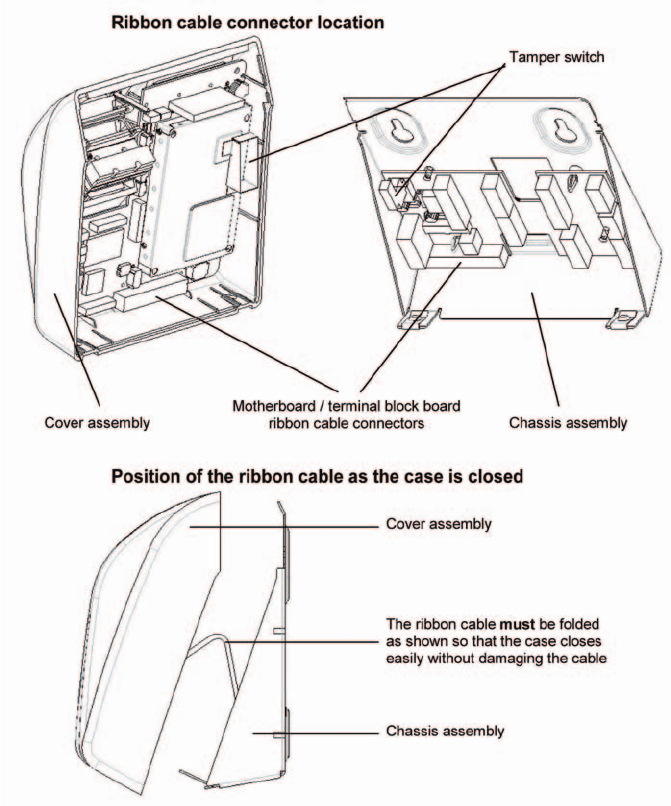
Stage 3: Connecting the chassis assembly to the cover
assembly
Installation procedure-Stage 3
8
9
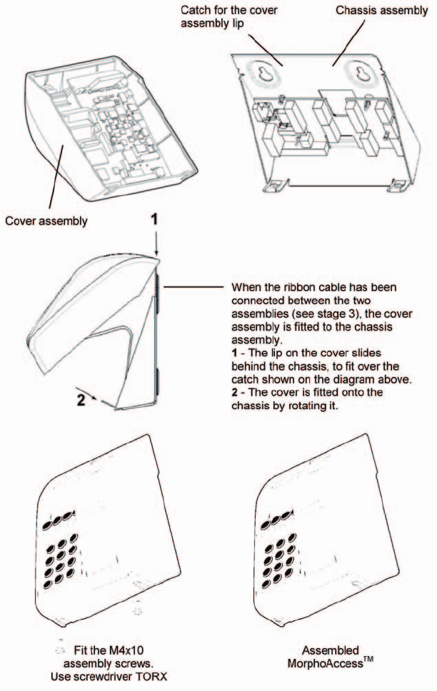
Stage 4: Closing MorphoAccess™
Installation Procedure -Stage 4
8
9
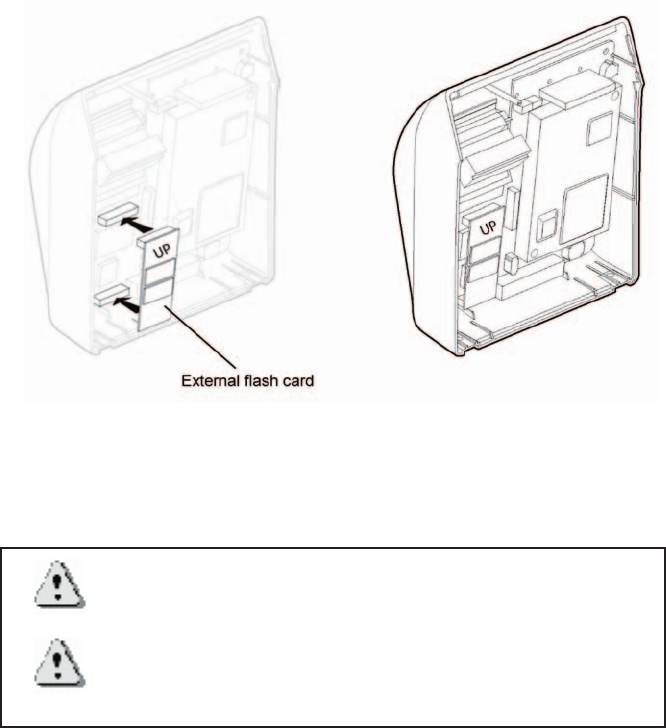
How to upgrade MorphoAccess™ 200 to 300
This operation requires that the MorphoAccess™ is powered off.
When the optional ash card is inserted, the MorphoAccessTM
200 becomes a MorphoAccessTM 300. All subsequent database
information will be stored on the new media.
Warning: All database information of the MorphoAccessTM 200
is lost.
Warning: When transferring an external ash card from a
MorphoAccessTM 300 to another, you will lose access to all
database information written on the card.
For more information, refer to the MorphoAccess™ Host System
Interface Specication.
Upgrade MorphoAccess™200 to MorphoAccess™300
10
11
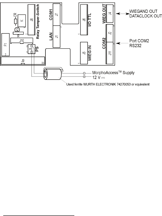
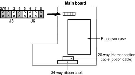
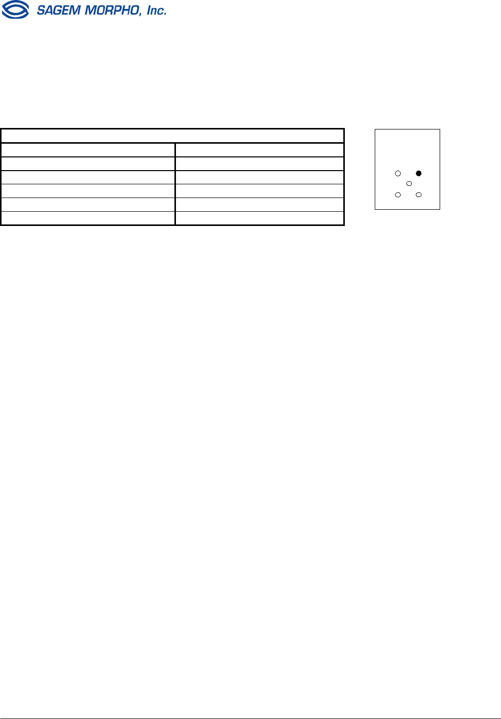
Electrical Interfaces
Terminal block board
For EMC compatibility: To be EC and FCC compliant (EN55022, EN55024
FCC part 15), each interface cable and 12V power supply cable must be
threaded and wrapped through an axial ferrite bead.
J1 5 pin block Ethernet Interface (LAN 10Mbps)
J3 2 pin block 12 V supply ± 5% regulated
J4 4 pin block Wiegand output to host or Data Clock output
J5 5 pin block Wiegand peripheral input or Data Clock output
J7 5 pin block COM1 RS485/422 serial interface
J8 7 pin block Output relay and Tamper-Switch
J11 5 pin block COM2 reduced RS232C serial interface
J9 34 way ribbon cable Connection to main assembly
F1 Fuse 2.5 A quick blow fuse
J2 9 pin block COM2 full RS232C serial interface (optional)1
J6 7 pin block 6 input/output 5 V TTL interface (optional)1
J10 20 way interconnection Connection to main assembly (optional)1
J11 5 pin block RS422 serial interface (optional)1
1For more information, please contact SAGEM MORPHO, Inc..
Electrical interfaces
2.5 A minimum
10
11
Power supply cable
The terminal blocks are shown viewed from the front with the
chassis assembly in its normal position on the wall.
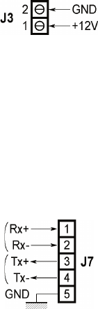
Terminal block J3
Pin 1 +12V Power
Pin 2 Ground Power
Power supply 12 V ± 5% (regulated) 2.5 A/min
COM1 RS485/422 serial port wiring
Terminal block J7
Pin 1 Rx+ Input
Pin 2 Rx- Input
Pin 3 Tx+ Output
Pin 4 Tx- Output
Pin 5 Ground Ground
For an RS485 multi drop (half duplex) connection, only Tx+, Tx-
and ground are connected. Otherwise, as the unit is a peripheral,
the connections must be crossed over: Rx on the MorphoAccessTM
is connected to Tx on the host and Tx on the MorphoAccessTM is
connected to Rx on the host.
Electrical interfaces
12
13
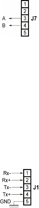
COM1 Deister wiring (optional)
Terminal block J7
Pin 3 A Input/Output
Pin 4 B Input/Output
To use the features of the optional Deister contactless card reader,
connect the AB wires to the Tx port.
AB wires are connected to the Deister contactless card reader as
dened in its installation manual.
For more information about this option, please contact your
MorphoAccess sales representative.
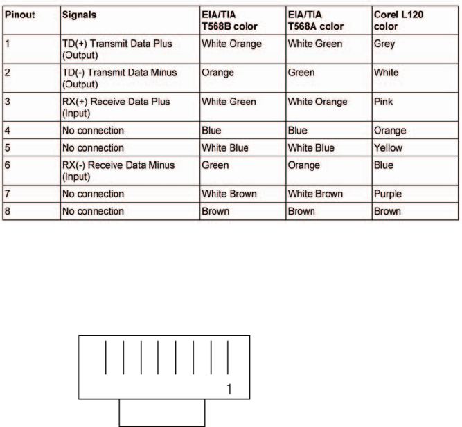
Ethernet wiring
Terminal block J1
Pin 1 Rx+ Input
Pin 2 Rx- Input
Pin 3 Tx+ Output
Pin 4 Tx- Output
Pin 5 Ground Ground
See Appendix 1, Ethernet color standard.
Electrical Interfaces
12
13
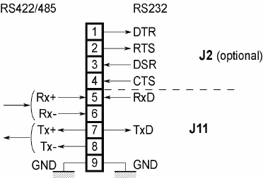
COM2 RS232 wiring
For a reduced RS232C (no handshake), only TxD, RxD and
ground are connected on J11.
Terminal block J11: Reduced RS232
Pin 5 RxD Input
Pin 6 Not connected
Pin 7 TxD Output
Pin 8 Not connected
Pin 9 Ground Ground
Terminal block J2/J11: Full RS232C (optional)
Pin 1 DTR (Connected to DSR on the host) Output
Pin 2 RTS (Connected to CTS on the host) Output
Pin 3 DSR (Connected to DTR on the host) Input
Pin 4 CTS (Connected to RTS on the host) Input
Pin 5 RxD (Connected to TxD on the host) Input
Pin 6 Not connected
Pin 7 TxD (Connected to RxD on the host) Output
Pin 8 Not connected
Pin 9 Ground Ground
Electrical Interfaces
14
15
COM2 RS422 wiring
COM2 can also be congured for RS422.
Terminal block J11: RS485/422 (optional)
Pin 1 Not connected
Pin 2 Not connected
Pin 3 Not connected
Pin 4 Not connected
Pin 5 Rx+ (Connected to Tx+ on the host) Input
Pin 6 Rx- (Connected to Tx- on the host) Input
Pin 7 Tx+ (Connected to Rx+ on the host) Output
Pin 8 Tx- (Connected to Rx- on the host) Output
Pin 9 Ground Ground
Warning: Except for reduced RS232C (TXD, RxD and GND),
the options full RS232C and RS485/422 need the optional
cable on J10.
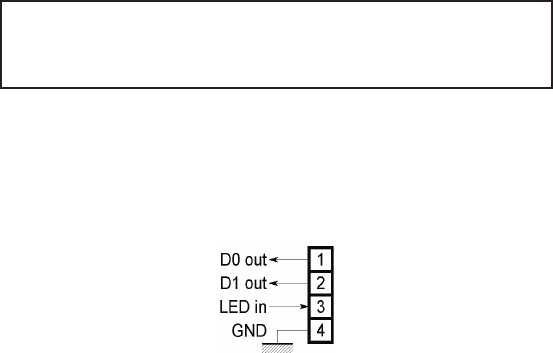
Wiegand output wiring
Terminal block J4
Pin 1 Data 0 Output
Pin 2 Data 1 Output
Pin 3 LEDin Input
Pin 4 Ground Input
The electrical interface conforms to the Security Industry
Association’s Wiegand standard, March 1995.
Electrical Interfaces
14
15
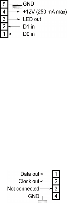
Wiegand input wiring
Terminal block J5
Pin 1 Data0 Input
Pin 2 Data0 Input
Pin 3 LEDout Output
Pin 4 +12V Power
Pin 5 Ground Input/Output
The electrical interface conforms to the Security Industry
Association’s Wiegand standard, March 1995.
Data clock output wiring
Terminal block J4
Pin 1 Data Output
Pin 2 Clock Output
Pin 3 NC
Pin 4 Ground Ground
The electrical interface is 5 V TTL.
Electrical Interfaces
16
17
Data clock input wiring
Terminal block J5
Pin 1 Data Input
Pin 2 Clock Input
Pin 3 NC
Pin 4 NC
Pin 5 Ground Ground
The electrical interface is 5 V TTL compatible.
Electrical interfaces
16
17
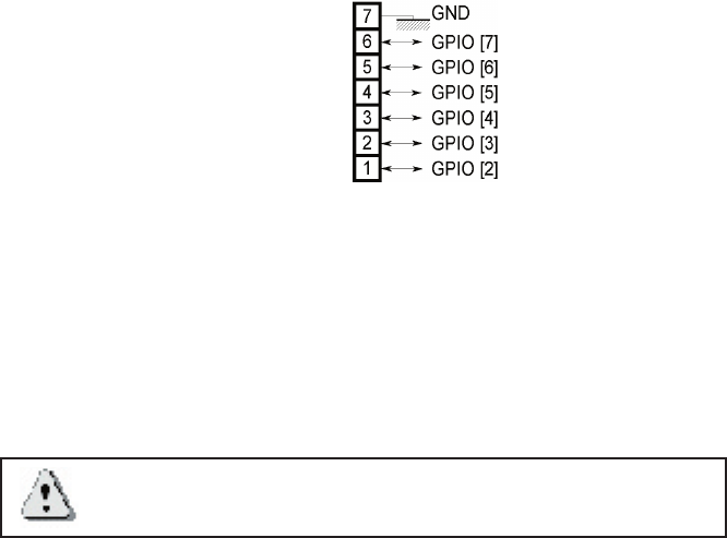
Input / output wiring (optional)
Input / Output
Terminal block J6
Pin 1 GPIO[2] Input /Output
Pin 2 GPIO[3] Input /Output
Pin 3 GPIO[4] Input /Output
Pin 4 GPIO[5] Input /Output
Pin 5 GPIO[6] Input /Output
Pin 6 GPIO[7] Input /Output
Pin 7 Ground Ground
Warning: This option requires the optional cable on J10.
Electrical interfaces
18
19
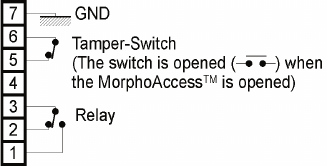
Output relays and Tamper switch
A three-pin output relay is available. It has a common contact, a
normally open contact and a normally closed contact.
Terminal block J8
Pin 1 Normally open
Pin 2 Normally closed
Pin 3 Common
Pin 4 Unused
Pin 5 Tamper switch
Pin 6 Tamper switch
Pin 7 Ground Ground
Relay ratings
1 A at 30 VDC according to the extra low voltage safety
requirements (42.4 VAC max, 60 VDC max) independent of the
power supply.
Electrical interfaces
18
19
Conguring the MorphoAccessTM
Motherboard conguration
SW1: Wiegand input
Open = Wiegand Mode
Closed = Dataclock Mode
SW2: Wiegand output
Open = Wiegand Mode
Closed = Dataclock Mode
SW3-6: Reserved for future use
SW3 must be open
SW4 must be closed
SW5 must be open
SW6 must be open
SW7-8: Wiegand Input (Interrupts)
Open Open = Not allowed
Closed Open = Wiegand Mode
Open Closed = Dataclock Mode, default
Closed Closed = Not allowed
Conguring the MorphoAccess™
20
21
Optional communications cable
If your installation requires complete RS232 or RS485/422 COM2
or I/O TTL communications, an optional 20 wire cable is required
between the MorphoAccessTM motherboard and the terminal
block board (J10). Contact your MorphoAccess vendor for more
information.
Conguring the MorphoAccess™
20
21
MorphoAccess™ Technical characteristics
Display
• Back-lit LCD 136 x 34 pixels
Keyboard
• Back-lit with 12 numerical keys
• With 4 functions keys
Fuse
• 2.5 A quick blow
Memory
• 512 Kbytes
• Optional 32-Mbyte Flash memory for data storage only on MA
300
Peripherals interfaces
• COM1 RS422/RS485
• COM2 RS232 or optional RS422/RS485
• Ethernet 10 Base T
• Wiegand or Dataclock ISO2 output
• Wiegand or Dataclock ISO2 input
• 6 optional I/O
• Relay
• Tamper switch.
Technical characteristics
22
23
Power supply
• 12 V ± 5% 2.5 A minimum power supply
Cable cross section depends on the length: 0.75 mm²
recommended
Size and weight
This product is designed for indoor use only.
• 70 x 160 x 145 mm
• 750 g
Environmental conditions
• Operating temperature + 0°C to + 40°C
• Humidity 10% < RH < 80%
• Light The MorphoAccessTM should be
installed in controlled lighting
conditions (avoid direct exposure
to sunlight)
• UV Avoid exposure to UV
Storage conditions
• Temperature - 20°C to 70°C
• Humidity < 95%
Technical characteristics

22
23
Recommendations
Areas containing combustibles
It is strongly recommended that you do not install your
MorphoAccess™ in the vicinity of gas stations, petroleum
processing facilities or any other facility containing amable or
combustable gasses or materials.
General precautions
• Do not attempt to repair your MorphoAccess™ yourself. The
manufacturer cannot be held responsible for any damage/
accident that may result from attempts to repair components.
• Any work carried out by non-authorized personnel will
invalidate your warranty.
• Do not use your MorphoAccess™ in damp areas. Protect it
from water and other liquids.
• Do not expose your MorphoAccess™ to extreme
temperatures.
• Use your MorphoAccess™ with original accessories.
Attempts to integrate the MorphoAccess™ with unapproved
accessories will void your warranty.
• Due to electrostatic discharge, and depending on the
environment, synthetic carpet should be avoided in areas
where the MorphoAccess™ has been installed.
Warning: The manufacturer cannot be held responsible
if the above recommendations are not followed or if the
MorphoAccess™ is incorrectly used.
Recommendations
24
25
Appendix 1 - Ethernet color standard
RJ45 Pinout
Compliant with 10 base T IEEE Specication.
Appendix 1
24
25
Appendix 2 - Wiegand data format
The 26 bits of transmission consists of two parity bits and 24 code
bits. The 8 rst code bits are encoding the facility code. This code
identies each MorphoAccessTM in a network. The 16 other bits
are data bits. The rst bit transmitted is the rst parity bit. It is even
parity calculated over the rst 12 bits. The last bit transmitted is
the second parity bit. It is odd parity bit calculated over the last
12 code bits.
Even parity (1 bit) Facility code (8 bits) Data (16 bits) Odd parity (1 bit)
Compliant with access control 26-Bit - Wiegand reader interface
standard 03/1995.
Appendix 2

26
27
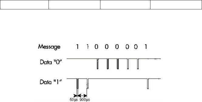
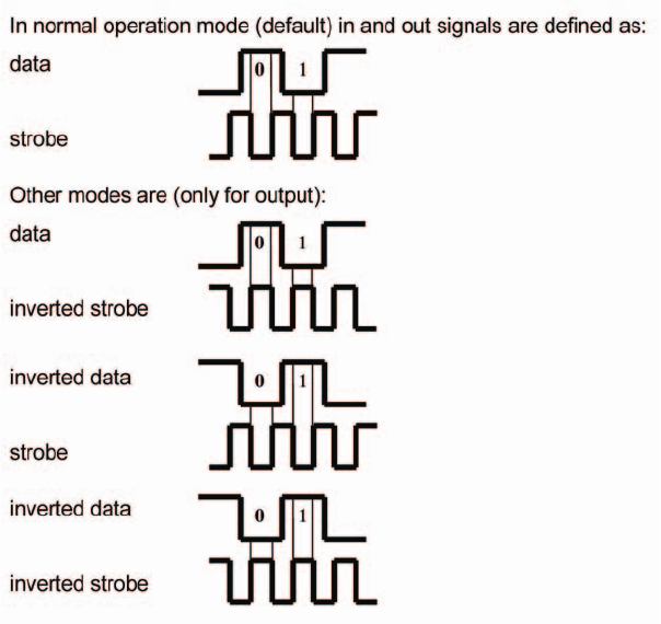
Appendix 3 - ISO 7811/2-1995 - Track 2 Dataclock format
Compliant with ISO07811/2-1995 - Track 2.
Data encoding table
Value Bitpattern Meaning
0 0 0 0 0-1 “0”
1 1 0 0 0-0 “1”
2 0 1 0 0-0 “2”
3 1 1 0 0-1 “3”
4 0 0 1 0-0 “4”
5 1 0 1 0-1 “5”
6 0 1 1 0-1 “6”
7 1 1 1 0-0 “7”
8 0 0 0 1-0 “8”
9 1 0 0 1-1 “9”
10 (Ahex) 0 1 0 1-1 unused character
11 (Bhex) 1 1 0 1-0 start sentinel (start character)
12 (Chex) 0 0 1 1-1 unused character
13 (Dhex) 1 0 1 1-0 eld separator
14 (Ehex) 0 1 1 1-0 unused character
15 (Fhex) 1 1 1 1-1 end sentinel (stop character)
The least signicant bit of every digit is sent rst; the fth bit is an
odd parity bit for each group of 4 data bits.
The complete message always looks as follows:
left edge start data characters end LRC right edge
The LRC is calculated by the following procedure: each of the
4 bits in the LRC character is an even parity bit of the equivalent
bits in the telegram including start and stop sentinel.
The fth bit is the odd parity of the 4 LRC bits (it is not calculated
over all the parity bits).
Appendix 3
26
27
Dataclock levels
Appendix 3
28
29
Appendix 4 - Reserved conguration keys
Those keys are for internal use only.
For proper operation, this settings should not be changed.
/cfg/lcd0/display/type : 1
/cfg/lcd0/contrast/value : 0
/cfg/serx/mode/connection: EXT
/cfg/serx/mode/mode: 450
db/seq ash/start: 0
/cfg/bio/video/channel: 0
/cfg/bio/video/rotation: 0
/cfg/lic/licences/*
Appendix 4
28
29
Appendix 5 - MORPHO® BRAND BIOMETRIC
PRODUCT
WARRANTY, LIMITATIONS, AND SOFTWARE
LICENSE
1. LIMITED WARRANTY AND MAINTENANCE. Subject to the Disclaimers and
Limitations of Warranty set forth below, SAGEM MORPHO, Inc., (hereinafter “SMI,” or
its licensed reseller, as may be applicable) provide the following limited warranty, for the
benet of original Customer only, that all hardware components of the Morpho® brand
biometric product with which this information is associated will conform to the applicable
hardware product specications as published by SMI and will be in good working
order and free from material defects in materials or workmanship, given Customer’s
normal use and service (the “Hardware Limited Warranty”). It is further warranted that
the Morpho® brand biometric software provided with, and/or loaded into and resident
in the biometric product will conform to the applicable software specications or SMI
documentation published by SMI, given Customer’s normal use and operation (the
“Software Limited Warranty”). Any and all third party software programs supplied with
the biometric product are subject to their respective manufacturer’s warranty and license
terms only, and SMI assumes no responsibility for such software.
The Hardware Limited Warranty extends for one (1) year from the date of Customer’s
receipt of delivery of the biometric product. The Software Limited Warranty extends for
ninety (90) days from the date of Customer’s receipt of delivery of the biometric product.
During the duration of the Hardware and Software Limited Warranties, the rst level
of support shall be provided by telephone “Help Desk” support (the applicable Help
Desk telephone number is included with the packaged biometric product). Hardware
repairs which cannot be remedied through Help Desk consultation shall be made by
returning the hardware component to an authorized SMI service depot, in accordance
with instructions issued by the service depot, at Customer’s expense. Return delivery
of the repaired or replaced component shall be at SMI’s expense. SMI shall repair or
replace any nonconforming hardware component at its sole election. Software problems
not remedied through Help Desk consultation may be corrected through software
patches or updates issued by SMI or by replacement of the unit in which the
software is resident, at SMI’s sole election. The Limited Software Warranty
does not entitle the customer to automatically receive patches, updates or other
notication of software correction or revision during the duration of the warranty.
The original warranty periods shall not be renewed or extended by subsequent
repair or replacement.
Biometric product maintenance after expiration of the one (1) year warranty may
be available pursuant to the terms and conditions of a separate Maintenance
Agreement – please contact the location from which the biometric product was
Appendix 5
30
31
purchased for further details.
2. LIMITATIONS AND DISCLAIMERS OF WARRANTY. SMI does not
warrant that operation of the biometric product will be uninterrupted or error-free;
further, no biometric product or system can be guaranteed to be 100% accurate, or to
properly enroll, identify, or authenticate every individual. SMI shall have no responsibility
for repairing or otherwise remedying any defect or nonconformity in the condition or
operation of the biometric product or its software if: 1) modications to Customer’s site
are necessary for proper operation, and Customer’s site preparation is inadequate;
2) the biometric product is not professionally installed in accordance with applicable
industry standards, local building/zoning codes such as the National Electric Code, and
proper installation practices; 3) the biometric product is not maintained and operated
with all proper accessories under normal conditions by competent personnel; 4)
the biometric product incorporates replacement parts not authorized by SMI; 5) the
biometric product has been subjected to disassembly except as required for normal
installation, modication beyond what is described in SMI-supplied installation and
operation guides, unauthorized enhancement, abuse or misuse; or 6) the defect or
nonconformity has not been reported to the designated Help Desk within ten (10)
days of its discovery by Customer. As Customer’s sole and exclusive remedy for any
nonconformity or defect in the condition or operation of the biometric product for which
SMI is responsible, SMI shall provide its reasonable efforts to remedy same as set forth
in Section 1, above during the applicable stated Limited Warranty Period. With the
exception of its Limited Warranties set forth in Section 1, above, TO THE MAXIMUM
EXTENT ALLOWED BY APPLICABLE LAW, SMI DISCLAIMS ANY AND ALL
PROMISES, REPRESENTATIONS AND WARRANTIES, EXPRESS OR IMPLIED,
WITH RESPECT TO THE BIOMETRIC PRODUCT, ITS HARDWARE, SOFTWARE,
DESIGN, OR FUNCTIONALITY, OR ITS MERCHANTABILITY OR FITNESS FOR ANY
PARTICULAR PURPOSE, OR ARISING FROM USAGE OF TRADE, COURSE OF
DEALING, OR COURSE OF PERFORMANCE. SMI FURTHER DISCLAIMS ANY AND
ALL PROMISES, REPRESENTATIONS AND WARRANTIES, EXPRESS OR IMPLIED,
WITH RESPECT TO ANY OF SMI’S SERVICES PERFORMED HEREUNDER.
3. LIMITATIONS OF LIABILITY. The entire liability of SMI to Customer (or
to any person or entity claiming through Customer) for any claim whatsoever related
to the biometric product or the parties’ transaction shall not exceed the total amount
of all payments made for the biometric product by Customer to the date of the claim.
IN NO EVENT SHALL SMI BE LIABLE TO CUSTOMER FOR ANY LOST PROFITS,
LOST INFORMATION, BUSINESS INTERRUPTION, OR OTHER CONSEQUENTIAL,
INCIDENTAL, SPECIAL, PUNITIVE OR INDIRECT DAMAGES (WHETHER IN AN
ACTION IN CONTRACT OR TORT OR BASED ON WARRANTY), EVEN IF SMI HAS
BEEN ADVISED OF THE POSSIBILITY OF SUCH DAMAGES, ARISING OUT OF,
OR RELATED TO, THE BIOMETRIC PRODUCT OR THE PARTIES’ TRANSACTION.
Some jurisdictions do not allow excluding or limiting implied warranties, or limiting
liability for incidental or consequential damages, and some jurisdictions have special
statutory consumer protection provisions that may supersede this limitation. As a result,
the limitations and disclaimers of warranty and liability set forth herein may not apply to
Customer if prohibited by the laws of Customer’s jurisdiction.
4. RESTRICTION ON EXPORTATION. Certain biometric products and
associated software may have restrictions upon their exportation outside the United
States of America, and the applicable U.S. Government regulations and restrictions are
Appendix 5
30
31
subject to frequent change. Customer shall comply with all applicable laws, rules and
regulations of governmental authorities, now or hereafter in effect, including, without
limitation, the U.S. Export Administration Act and other U.S. export controls. Customer
agrees that Customer will not export or re-export, directly or indirectly, the SMI biometric
products or software to any country, person, or entity subject to U.S. export restrictions.
Appendix 5
32
33
Drilling Template
.
32
33

34

M
Mo
or
rp
ph
ho
oA
Ac
cc
ce
es
ss
s™
™
T
Te
er
rm
mi
in
na
al
l
I
In
ns
st
ta
al
ll
la
at
ti
io
on
n
G
Gu
ui
id
de
e
U
Up
pd
da
at
te
e
M142-005C
September 2003
SAGEM MORPHO, Inc.
Tacoma, Washington 98402

2 SAGEM MORPHO, Inc. 2003. All rights reserved. SEPTEMBER 2003
Contents
FCC Compliance of MorphoAccess™ 200, 220, 300, 200E, 220E, and 300E ......................3
Installing Ferrite Beads on Interface Cables for MorphoAccess™ 200 and 300 ....................3
Installing Ferrite Beads on Interface Cables for MorphoAccess™ 220 ..................................5
MorphoAccess™ Motherboard Jumper Configuration............................................................7
MorphoAccess™ Serial Port is RS-422 Only .........................................................................8
Ethernet Connections to MorphoAccess™.............................................................................8
MorphoAccess™ 300 Memory Extension Board....................................................................8
MorphoAccess™ Power Supply Selection Outside the United States....................................8
MorphoAccess Installation Guide Update SAGEM MORPHO, Inc. 2003. All Rights
Reserved.
This manual, as well as the software described in it, is furnished under license and may be
used or copied only in accordance with the terms of such license. The content of this
manual is furnished for informational use only, is subject to change without notice, and
should not be construed as a commitment by SAGEM MORPHO, Inc. SAGEM MORPHO, Inc.
assumes no responsibility or liability for errors or inaccuracies that may appear in this
documentation, and it is furnished “AS IS,” with no warranties of any kind, express or
implied. Except as may be permitted by the license, no part of this manual may be
reproduced, stored in a retrieval system, or transmitted in any form or by any means,
without the prior written permission of SAGEM MORPHO, Inc.
“SAGEM,” “MORPHO,” and the SAGEM logo are U.S. registered trademarks of SAGEM SA.
All other product and company names which may be referenced herein are trademarks or
servicemarks of their respective owners.
MorphoAccess Terminal Installation Guide Update, Document M142-005C
SAGEM MORPHO, Inc., 1145 Broadway Plaza, Tacoma, WA 98402 USA
September 2003

SEPTEMBER 2003 SAGEM MORPHO, Inc. 2003. All rights reserved. 3
FCC Compliance of MorphoAccess™ 200, 220, 300,
200E, 220E, and 300E
This device complies with part 15 of the FCC Rules. Operation is subject to the following two
conditions: (1) This device may not cause harmful interference, and (2) this device must
accept any interference received, including interference that may cause undesired
operation.
This FCC compliance is for MorphoAccess™ products as delivered to you, the customer.
Any changes or modifications not expressly approved by SAGEM MORPHO, Inc. could void
your authority to operate MorphoAccess™ products.
Installing Ferrite Beads on Interface Cables for
MorphoAccess™ 200 and 300
This document provides an overview of ferrite beads and explains how to install them on the
power, Wiegand, RS-422, and Ethernet cables that you connect to the MorphoAccess™ 200
or 300. To meet FCC requirements for Class B computing devices, a ferrite bead must be
installed on every cable connected to the MorphoAccess 200 or 300 — only if the
MorphoAccess serial number starts with 01 or 02.
What is a Ferrite Bead?
Ferrite beads are radio frequency (RF) absorbers. To see an example of a ferrite bead, look
at a monitor video cable or a laptop computer power cable that is connected to your
computer. The walnut-sized protrusion that is molded near one end of the cable is a ferrite
bead. The size and shape of the ferrite bead determines the amount of RF that is absorbed.
The amount of RF that a device emits determines the type of ferrite bead that is required to
provide the proper absorption.
The ferrite beads supplied with your MorphoAccess 200 or 300 terminal have been properly
sized to absorb the correct amount of RF to comply with FCC requirements.
Installing a Ferrite Bead
Check the serial number on the back of the MorphoAccess. If the serial number starts with
01 or 02, install one ferrite bead on each cable before you install the MorphoAccess 200 or
300 terminal.
4 SAGEM MORPHO, Inc. 2003. All rights reserved. SEPTEMBER 2003
Ordering Ferrite Beads
To order more ferrite beads (Ferrico F5-NF-80B) for your MorphoAccess 200 or 300
interface cable, contact SAGEM MORPHO, Inc. at 1-800-526-2674. Ask for part number
1205-294001-0.
1. Select the interface cable that you want to
work with and open a ferrite bead by releasing
the clasps on the side.
2. Position the ferrite bead on the cable as close
as possible to (but not inside) the
MorphoAccess.
Lay the cable inside the groove.
3. Bend the cable around the ferrite bead to form a
loop and lay it again inside the ferrite bead.
Make sure the cable circles the ferrite bead so
that it passes through the ferrite bead twice.
4. Close the two halves of the ferrite bead and
securely fasten the clasps without pinching the
cables.
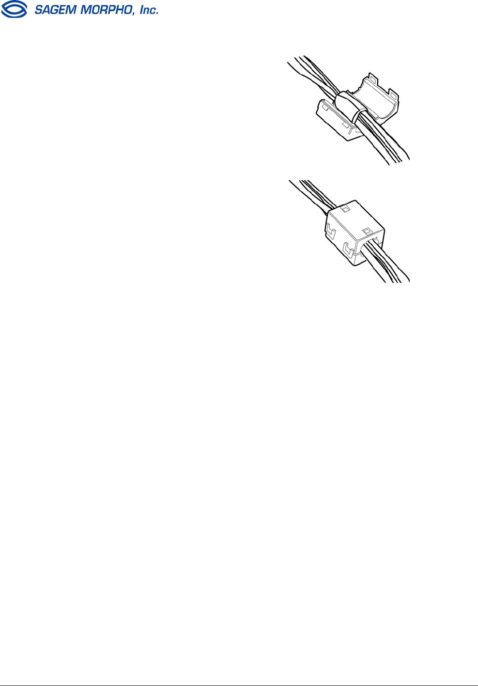
SEPTEMBER 2003 SAGEM MORPHO, Inc. 2003. All rights reserved. 5
Installing Ferrite Beads on Interface Cables for
MorphoAccess™ 220
This document provides an overview of ferrite beads and explains how to install them on the
power, Wiegand, RS-422, and Ethernet cables that you connect to the MorphoAccess™
220. To meet FCC requirements for Class B computing devices, a ferrite bead must be
installed on all cables connected to the MorphoAccess.
What is a Ferrite Bead?
Ferrite beads are radio frequency (RF) absorbers. To see an example of a ferrite bead, look
at a monitor video cable or a laptop computer power cable that is connected to your
computer. The walnut-sized protrusion that is molded near one end of the cable is a ferrite
bead. The size and shape of the ferrite bead determines the amount of RF that is absorbed.
The amount of RF that a device emits determines the type of ferrite bead that is required to
provide the proper absorption.
The ferrite beads supplied with your MorphoAccess 220 terminal have been properly sized
to absorb the correct amount of RF to comply with FCC requirements.
Installing a Ferrite Bead
After all the cables have been routed through the wall, place a single ferrite bead around all
of them before you install the MorphoAccess 220 terminal. See instructions below. The
foam strip will be compressed in the ferrite bead to prevent the ferrite bead from slipping
down the cable.
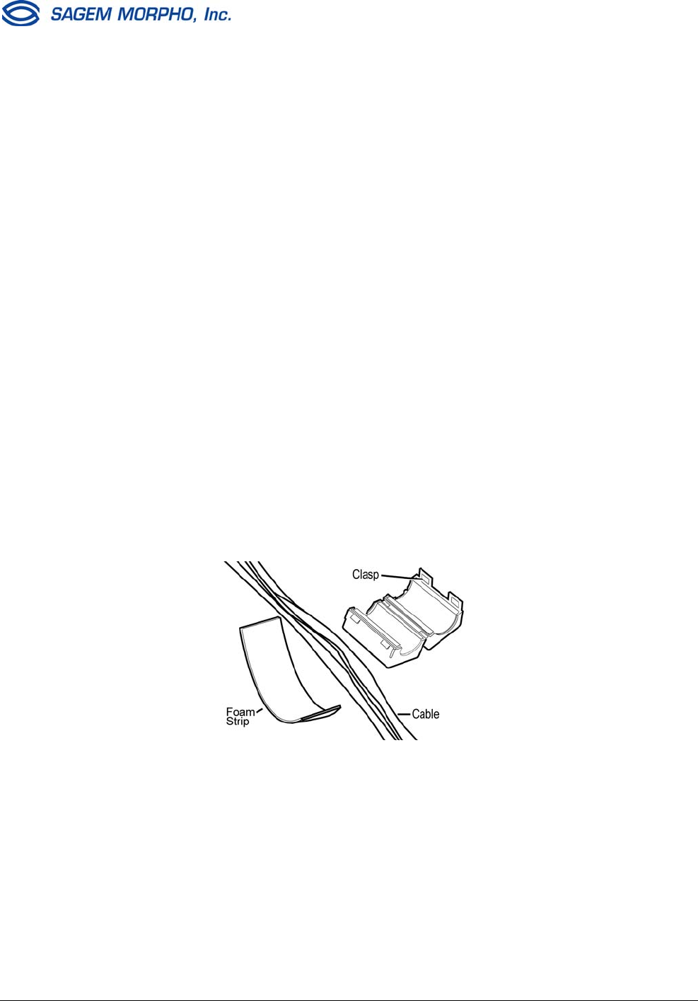
1. Open a ferrite bead by releasing the clasp on the side.
2. Determine where the ferrite bead will be positioned on the cables. It should be
positioned as close as possible (but not inside) to the MorphoAccess terminal.
Ensure that sufficient cable slack will be available to route the cables inside the
MorphoAccess and to attach the wires to the terminal block.
6 SAGEM MORPHO, Inc. 2003. All rights reserved. SEPTEMBER 2003
3. Wrap the foam tightly around all the
cables at the position where the ferrite
bead will be placed.
4. Lay the foam-wrapped cable inside the
groove of the ferrite bead.
5. Close the two halves of the ferrite bead
and securely fasten the clasps.
If the ferrite bead does not close easily,
trim the foam slightly, but not so much
that the ferrite bead will slide away from
the terminal.
Ordering Ferrite Beads or Foam Cable Wrap for Ferrites
To order more ferrite beads (Fair-Rite 04441 73551) for your MorphoAccess 220 interface
cables, contact SAGEM MORPHO, Inc. at 1-800-526-2674. Ask for part number 1205-364001-
0. To order more foam cable wrap for ferrites, ask for part number 0999-900019-0.
SEPTEMBER 2003 SAGEM MORPHO, Inc. 2003. All rights reserved. 7
MorphoAccess™ Motherboard Jumper Configuration
SW1: Wiegand input
Open = Wiegand Mode (default)
Closed = Dataclock Mode
SW2: Wiegand output
Open = Wiegand Mode (default)
Closed = Dataclock Mode
SW3-6: Reserved (MA200/300)
SW3 must be open =
SW4 must be closed =
SW5 must be open =
SW6 must be open =
SW3-6: Reserved (MA220)
SW3 must be closed
SW4 must be open
SW5 must be open
SW6 must be closed
SW7-8: Wiegand Input (Interrupts)
Open Open = Not allowed
Closed Open = Wiegand Mode (default)
Open Closed = Dataclock Mode
Closed Closed = Not allowed
8 SAGEM MORPHO, Inc. 2003. All rights reserved. SEPTEMBER 2003
MorphoAccess™ Serial Port is RS-422 Only
The COM1 serial port supported in all MorphoAccess™ products is RS-422 only, not RS-
485 as shown in the installation guides. Below is the correct RS-422 wiring diagram for
MorphoAccess™ 200E, 220E, and 300E (outdoor units).
RS-422 Cable
Color/stripe Function
White/Green RX+
Green/White RX-
White/Orange TX+
Orange/White TX-
Blue/White GND
Ethernet Connections to MorphoAccess™
It is recommended to use shielded category 5 (Cat 5) Ethernet cable (120 ohm impedance).
It is also strongly recommended to install a repeater unit every 300 ft (90 m). Extreme care
must be taken when connecting the Ethernet wires to the terminal block board during
installation, since low quality connections may degrade the Ethernet signal sensitivity. The
receive wires Rx+ and Rx- should be connected from the same twisted pair of wires, and the
transmit wires Tx+ and Tx- should also be connected from the same twisted pair of wires.
MorphoAccess™ 300 Memory Extension Board
Under certain very harsh shipping conditions, the memory extension board of the
MorphoAccess™ 300 (indoor MorphoAccess only) might become disconnected. You should
check that the memory board is properly attached before connecting power to the
MorphoAccess 300. When you disassemble the MorphoAccess 300 to mount it on a wall,
make sure the memory board is properly aligned with the pins (see page 9 of the Installation
Guide). There are two sets of 26 connector pins, but each connector on the memory
extension board has only 24 socket holes. Align the memory extension board such that it
uses the sets of 24 pins closest to the large silver shield. Push on the memory extension
board to make sure it is firmly seated on the connector pins.
MorphoAccess™ Power Supply Selection Outside the
United States
When any model MorphoAccess™ is installed, it is the responsibility of the installer to
provide an IEC 60950-certified power supply that is marked Limited Power Source (or
“LPS”) and rated at 12 VDC, 2.5 A minimum. This applies to indoor units (MA200, 220, and
300) as well as outdoor units (MA200E, 220E, and 300E).
i
i
CONTENTS
Introduction 1
MorphoAccess™ Software User Interface V.4.2 23
Applicant recognition application 23
MorphoAccess Software Administrator Interface 31
Biometric management operations 32
Access the set up functions of the system 37
The CONFIG menu 39
The VERSION menu 69
The SERIAL NUMBER menu 70
The SETTING menu 71
Communication protocol 75
Appendix 1 - Wiegand data format 76
Appendix 2 - ISO 7811/2-1995 - Track 2 Data clock format 77
Appendix 3 - Reserved conguration values 79
Product Warranty, Limitations and Software License 80
End User Software License 82
Contents
1
1
Thanks for choosing the MorphoAccess™ Automatic Fingerprint
Recognition Terminal. MorphoAccess provides an innovative
and effective solution for access control or time and attendance
applications using ngerprint verication and/or identication.
The MorphoAccess terminal integrates SAGEM image
processing and feature matching algorithms (MorphoSoft™
and MorphoImaging™). This technology is based on lessons
learned during 18 years of experience in the eld of biometric
identication and the creation of literally millions of individual
ngerprint identication records.
We believe you will nd the MorphoAccess fast, accurate, easy
to use and suitable for physical access control or time and
attendance.
The MorphoAccess offers the following advantages:
• Has a high quality optical scanner.
• Supports multiple input/output interfaces used in the physical
access control industry.
• Has a local area network interface for easy interaction with
other host systems.
• Is compact in size for easy installation and integration into
your available ofce space.
• Has an Intuitive interface that is easy to use in both setup
and operational modes.
• Has extensive, flexible flash memory for data storage,
including user data and biometric templates.
Introduction
Introduction
2 3
This guide allows you to congure the software parameters to
meet your installation requirements.The following lists some of
the congurable parameters:
• Administrator mode versus User mode
• Identication versus Authentication
• Standalone versus Client/Server
• Database management functions – enroll or delete
• Congure network parameters
• Congure juvenile processing
• Set matching threshold
• Set language preference – English, French, or Spanish
• Congure Welcome message
• Setup Wiegand and Data clock codes/parameters
• Congure COM port
• Congure relays
• Adjust contrast and brightness
• Set clock
To ensure the most effective use of your MorphoAccess, we
recommend that you read this Software Guide in its entirety.
Introduction
SE32/03-011145-01 SAGEM SA document. Reproduction and disclosure forbidden. 23
E
S
MORPHOACCESSTM SOFTWARE USER INTERFACE
The SAGEM SA MorphoAccess™ terminal can operate in three
modes: access control by identification, access control by
authentication and proxy mode. Those modes are set in the
Maccess/Admin/Mode configuration key.
The MorphoAccess™ 200 manages one base of 800(1) persons,
locally or remotely. MorphoAccess™ 300 manages 16 bases of
3000 persons, remotely(2).
Access control by identification (MorphoAccess™ 200)
To configure MorphoAccess™ terminal in this mode, use the
system and edit /cfg/Maccess/Admin/mode, then enter 0.
After starting the MorphoAccess™ terminal, waits for fingerprint
detection in identification mode.
(1) In stand alone mode, the local base is sized for 800 persons, 2 fingers.
In MMS mode, it is possible to manage up to 1000 persons in a base, 2 fingers.
(2) For more information, see MorphoAccess™ Host System Interface Specification
Ref.: 3000005996.
Place your finger
for identification
Please
manuel.book Page 23 Vendredi, 30. mai 2003 12:21 12
24 SAGEM SA document. Reproduction and disclosure forbidden. SE32/03-011145-01
E
S
If the identification is successful, the terminal triggers the access
or returns the corresponding ID to central security controller(3).
Once the person’s identification is done, the terminal automatically
loops back and waits for a new finger. This display remains for
about 4 seconds.
(3) Port used to exchange ID is either Weigand/Dataclock or COM1/COM2. The ID format send to COM port
is described on Communication protocol section.
Welcome
707251
IDENTIFIED
✔✔
✔✔
✔
manuel.book Page 24 Vendredi, 30. mai 2003 12:21 12
SE32/03-011145-01 SAGEM SA document. Reproduction and disclosure forbidden. 25
E
S
Access control by identification (MorphoAccess™ 300)
To configure the MorphoAccess™ in this mode, use Asystem and
edit /cfg/Maccess/Admin/mode, then enter 0.
After starting the MorphoAccess™ terminal, waits for fingerprint
detection in identification mode.
To select a user database, just press a key number to toggle the
base number. Only bases 0 to 15 can be selected and used.
Place your finger
for identification
Please
Base does not exist
Please select
another one
00
Place your finger
for identification
Please
Key 1 pressed
Key 1 pressed
Key 5 pressed
Original Identification
Screen using base 0
Now using base 1
Base 11 selected but
not used
01
11
manuel.book Page 25 Vendredi, 30. mai 2003 12:21 12
26 SAGEM SA document. Reproduction and disclosure forbidden. SE32/03-011145-01
E
S
If the identification is successful, the terminal triggers the access
or returns the corresponding ID to central security controller.
Once the person’s identification is done, the terminal automatically
loops back, selects base 0 and waits for a new finger. This display
remains for about 4 seconds.
Access control by authentication (MorphoAccess™ 200
and 300)
To configure the MorphoAccess™ in this mode, use Asystem and
edit /cfg/Maccess/Admin/mode, then enter 1.
This mode requires a peripheral equipment which will send the ID
of the person to authenticate to the MorphoAccess™ Wiegand or
Dataclock input.
Place your finger
for identification
Please
Place your finger
for identification
Please
Key 3 pressed
Now using base 15
Now using base 0
because base 53
cannot be selected
15
00
Welcome
92716
IDENTIFIED
✔✔
✔✔
✔
00
manuel.book Page 26 Vendredi, 30. mai 2003 12:21 12
SE32/03-011145-01 SAGEM SA document. Reproduction and disclosure forbidden. 27
E
S
To trigger authentication:
−if using a MorphoAccess™ 300, select a valid user database as
described in paragraph "Access control by identification".
−pass the user badge so the external reader sends the user ID on
MorphoAccess™ Wiegand or Dataclock input.
If the ID exists in the selected database, the MorphoAccess™
performs an authentication using the biometric templates
associated to this ID.
If the authentication is successful, the terminal triggers the access
or returns the user ID to central security controller.
Once the person’s authentication is done, the terminal
automatically loops back, selects base 0 and waits for a new input
ID. This display remains for about 4 seconds.
When using this feature, ID should be a value between 0 and
65535.
Pass your badge
for Authentication
Please
00
Authentication of
ID 92716
Place your finger
00
Welcome
92716
AUTHENTICATED
✔✔
✔✔
✔
00
manuel.book Page 27 Vendredi, 30. mai 2003 12:21 12
28 SAGEM SA document. Reproduction and disclosure forbidden. SE32/03-011145-01
E
S
Access control by contactless authentication:
ID and templates on a MIFARE card
(MorphoAccess™ 220)
To configure the MorphoAccess in this mode, use Asystem and
edit /cfg/Maccess/Admin/mode, then enter 3.
To trigger authentication, users should present their MIFARE card
to the terminal. MorphoAccess™ will read the ID, the user’s name
and two biometric templates stored on the card.
Read templates are used for a 1:1 matching.
If the authentication is successful, the terminal triggers the access
or returns the user ID to central security controller.
Please present
Contactless
Smart Card
Authentication of
John Smith
Place your finger
Welcome
John SMITH
AUTHENTICATED
✔✔
✔✔
✔
manuel.book Page 28 Vendredi, 30. mai 2003 12:21 12
SE32/03-011145-01 SAGEM SA document. Reproduction and disclosure forbidden. 29
E
S
Access control by contactless authentication: ID on a
MIFARE card, local templates (MorphoAccess™ 220)
To configure the MorphoAccess in this mode, use Asystem and
edit /cfg/Maccess/Admin/mode, then enter 4.
To trigger authentication, users should present their MIFARE card
to the terminal. MorphoAccess™ will read the ID stored on the
card.
If the ID exists in the selected database, the MorphoAccess™
performs an authentication using the biometric templates
associated to this ID.
If the authentication is successful, the terminal triggers the access
or returns the user ID to central security controller.
Please present
Contactless
Smart Card
Authentication of
ID 92716
Place your finger
Welcome
92716
AUTHENTICATED
✔✔
✔✔
✔
manuel.book Page 29 Vendredi, 30. mai 2003 12:21 12
30 SAGEM SA document. Reproduction and disclosure forbidden. SE32/03-011145-01
E
S
Proxy mode
This mode allows to control the MorphoAccess™ remotely using a
set of biometric and database management function interface
access commands.
For more information, please contact SAGEM SA or refer to
document 3000005996 MorphoAccess™ Host System Interface
Specification.
To configure the MorphoAccess™ in this mode, use Asystem and
edit /cfg/Maccess/Admin/mode, then enter 2.
manuel.book Page 30 Vendredi, 30. mai 2003 12:21 12
SE32/03-011145-01 SAGEM SA document. Reproduction and disclosure forbidden. 31
E
S
MORPHOACCESSTM SOFTWARE ADMINISTRATOR
INTERFACE
Application of the SAGEM SA MorphoAccess™ terminal allows:
1. Biometric management operations
−Transfer of biometric data between the MorphoAccess™
terminal and MorphoAccess™ Management System (MMS).
−In stand alone without the MorphoAccess™ management
system (manages the biometric data in a local database on
the MorphoAccess™) (MorphoAccess™ 200 only).
−The MorphoAccess™ shall be configured in one of either of
these modes (see this chapter).
2. Access to the set up functions of the system (request
Administrator mode).
Note 1
The MMS handles the MorphoAccess™ through a set of
command exchanges (two-way commands to and from the MMS
server and the MorphoAccess™ terminal). If you wish to know
more about this protocol and the command set, please contact
SAGEM SA.
Note 2
For further information about the application protocol between
MorphoAccess™. and MMS, please contact SAGEM SA. The
specification document has the following reference:
MorphoAccess™ Host System Interface Specification
Ref.: 3000005996.
System overviewSystem overview
System overviewSystem overview
System overview
Wiegand / Dataclock
▼▼
▼▼
▼
▼▼
▼▼
▼
MorphoAccess™MorphoAccess™
MorphoAccess™MorphoAccess™
MorphoAccess™
COM1 RS422
COM2 RS232
Host local / MMS
Ethernet
Host local / MMS
manuel.book Page 31 Vendredi, 30. mai 2003 12:21 12
32 SAGEM SA document. Reproduction and disclosure forbidden. SE32/03-011145-01
E
S
Biometric management operations
Biometric Management between terminal and
MorphoAccess™ Management System (MMS)(4)
MorphoAccess™ terminal includes an interface layer to
communicate with the access control system or the MMS through
Ethernet, RS422 and RS232 (For more information, see section
Setting up Network Parameters).
The biometric management operations are:
−Insert template/ID in database: The terminal inserts a new
record in the database.
−Remove template/ID from database: The terminal removes the
record identified by the ID in the database.
−Update template/ID in database: The terminal changes the
template identified by the ID in the database.
−Download database: The terminal reads the new database and
installs it in a local database according to the database identifier.
If the MorphoAccess™ application receives the commands from
MMS it will switch to base management mode. The operations
sent by MMS are automatically registered in the database of the
MorphoAccess™ terminal.
Managing a base locally is not possible. All biometric data is stored
on the MMS and the terminal will act as a capture and send device
only.
To access the Administrator menu with a MorphoAccess™ 300,
first select the base in which the Administrator is enrolled then hit
the following keys in sequence <#>, <*> and <#>. With a
MorphoAccess™ 200 simply hit the following keys in sequence
<#>, <*> and <#>.
(4) For more information about MMS, please contact SAGEM SA.
manuel.book Page 32 Vendredi, 30. mai 2003 12:21 12
SE32/03-011145-01 SAGEM SA document. Reproduction and disclosure forbidden. 33
E
S
The next screen is the Administrator screen. The blinking red led
indicates that you are in administrator mode.
Biometric login is enabled if configuration key /cfg/Maccess/admin/
admin ident is set to 1.
This operation creates a database with ID 0. This database can
contain 800 records with two biometric data fields, an ID field and
an Administrator field.
In order to access the Control menu, the Administrator’s fingerprint
template or pin must be entered (the default PIN is 12345). To
enter the pin code(5) select the PIN menu.
You can use the correction key # to delete the last number hit. After
a valid pin code or an Administrator identification, you will see the
following screen:
(5) To change the pin code, see section Use Application System.
Administrator identification
Place your Finger
for identification
PIN EXIT
Administrator identification
Enter Pin : I
OK EXIT
Press <#> for correction
Administrator Mode
Select a command Please
SYSTEM EXIT CL KEYS
manuel.book Page 33 Vendredi, 30. mai 2003 12:21 12
34 SAGEM SA document. Reproduction and disclosure forbidden. SE32/03-011145-01
E
S
Biometric management in stand alone(6) (MorphoAccess™
200 only)
In stand alone mode, the MorphoAccess™ manages its own local
database. This can be setup through the Administrator menus. On
the keypad, hit the following keys in sequences <#>, <*> and <#>.
The resulting screen is the Administrator menu.
Biometric login is enabled if configuration key /cfg/Maccess/admin/
admin ident is set to 1.
This operation creates a database with ID 0. This database can
contain 800 records with two biometric data fields, an ID field and
an Administrator field.
In order to access the Control menu, the Administrator’s fingerprint
template or pin code must be entered. To enter the pin code(7),
select the Pin menu.
You can use the correction key # to delete the last number hit.
(6) To change the Biometric management mode, see section Use Application System.
(7) To change the pin code, see section Use Application System.
Administrator identification
Place your Finger
for identification
PIN EXIT
Administrator Identification
Enter Pin : I
OK EXIT
Press <#> for correction
manuel.book Page 34 Vendredi, 30. mai 2003 12:21 12
SE32/03-011145-01 SAGEM SA document. Reproduction and disclosure forbidden. 35
E
S
If the identification is successful, the application allows access to
the biometric management functions. The biometric management
operations are:
−Insert template/ID in database (enrollment): The terminal inserts
a new record in the database.
−Remove template/ID from database (deletion): The terminal
removes the record identified by the ID in the database.
Insert template/ID in database (MorphoAccess™ 200 only)
To insert template/ID in local database, select the ENROLL menu.
You have to enter the ID of the person and validate it. The primary
and secondary fingers are requested and their corresponding
biometric templates are processed. If the process is successful,
then the person is registered in the local database.
You can use the correction key # to delete the last digit entered. In
the next screen you enroll your finger. Here You choose the user
type Administrator or User.
Administrator Mode
Select a command Please
ENROLL DEL EXIT
ERASE
Enrollment Mode
Enter Person ID : I
OK CANCEL
Press <#> for correction
manuel.book Page 35 Vendredi, 30. mai 2003 12:21 12
36 SAGEM SA document. Reproduction and disclosure forbidden. SE32/03-011145-01
E
S
Remove template/ID from database (MorphoAccess™ 200
only)
To remove a single template/ID record from the database, select
the DEL menu. You will then have to enter the ID of the person and
validate it. If the ID number does not exist in the local database, an
error message appears.
You can use the correction key # to delete the last digit entered.
Remove all template/ID from database (MorphoAccess™ 200
only)
To remove all records from the local MorphoAccess™ database,
select the ERASE menu option. A screen appears to confirm your
command.
Deletion Mode
Enter Person ID : I
OK CANCEL
Press <#> for correction
Do you really
want to ERASE
the Database
NO YES
manuel.book Page 36 Vendredi, 30. mai 2003 12:21 12
SE32/03-011145-01 SAGEM SA document. Reproduction and disclosure forbidden. 37
E
S
Access the set up functions of the system
To access the System Menu, you must leave the main application
of the MorphoAccess™. You must access the Administrator Menus
(see the section Biometric Management in Standalone) if you are
in fingerprint detection mode.
You must select the System Menu.
Then, select the ASYST menu to enter in the system application.
Enter the password to access to SYSTEM MENU (default value:
12345).
You can use the correction key # to delete the last digit entered.
The password can be changed in the configuration file
"/cfg/system" (see the section Setting up Administrator System
Pin). The System Menu will appear when the password is correct.
ASYSTE MACCESS
SYSTEM MENU
Enter Password:
OK CANCEL
Press <#> for correction
manuel.book Page 37 Vendredi, 30. mai 2003 12:21 12
38 SAGEM SA document. Reproduction and disclosure forbidden. SE32/03-011145-01
E
S
The CONFIG menu allows you to set up network and third-party
applications and specify additional parameters.
The VERSION item allows you to browse for software modules
present in your SAGEM MorphoAccess™ and see their revision
number(s).
The SER NB item displays the terminal serial number, MicroBoot
revision and Ethernet physical address of your machine.
The MORE key displays the rest of the system options.
The SETTING menu allows you to set the LCD contrast and the
time and date.
SYSTEM MENU
CONFIG VERSION MORE
SER NB
SYSTEM MENU
SETTING EXIT MORE
manuel.book Page 38 Vendredi, 30. mai 2003 12:21 12
SE32/03-011145-01 SAGEM SA document. Reproduction and disclosure forbidden. 39
E
S
The CONFIG menu
Unreferenced configuration keys are reserved by the application
and must not be changed(8).
Setting up Network Parameters
From the System Menu, press the CONFIG key to access the
configuration files. Press the NEXT key until the file menu shows
"/cfg/net".
−Press the EDIT key. The section menu will show "ip".
−Press the NEXT key until the address menu shows "address",
then press the EDIT key.
You can now edit the IP address of your SAGEM SA
MorphoAccess™.
The LEFT and RIGHT keys move the cursor. The alphanumeric
keys enter digits as necessary. The # key deletes the digit
immediately to the left of the cursor. The EXIT key aborts editing
and restores the previous address value.
(8) For default values, see appendix 4.
PREV NEXT EDIT
EXIT
FILE: cfg/net
PREV NEXT EDIT
EXIT
FILE: cfg/net
SECTION: ip
PREV NEXT EDIT
EXIT
FILE: cfg/net
SECTION: ip
address: 134.1.32.214
manuel.book Page 39 Vendredi, 30. mai 2003 12:21 12
40 SAGEM SA document. Reproduction and disclosure forbidden. SE32/03-011145-01
E
S
When finished editing, press the OK key to update the address
field and return to the previous screen.
The IP subnet mask and IP default gateway are set up in the same
way. Contact your network Administrator for these values.
Setting up the System Administrator Pin
From the Set up menu, press the CONFIG key to access the
configuration files. Press the NEXT key until the file menu shows
"/cfg/ system".
Press the EDIT key. The section menu will show "System". Press
the EDIT key again to show "Pwd". You can now edit the password
key to get access to system menu. The default value is "12345".
The LEFT and RIGHT keys move the cursor and the # key deletes
the digit immediately to the left of the cursor. The CANCEL key
aborts editing and restores the previous password value.
LEFT RIGHT OK
CANCEL
cfg/net ip
address
134.1.32.214
PREV NEXT EDIT
EXIT
FILE: cfg/system
SECTION: System
Pwd : 12345
manuel.book Page 40 Vendredi, 30. mai 2003 12:21 12
SE32/03-011145-01 SAGEM SA document. Reproduction and disclosure forbidden. 41
E
S
Setting up the MorphoAccess™ Administrator Pin
From the Set up menu, press the CONFIG key to access the
configuration files. Press the NEXT key until the file menu shows
"/cfg/ Maccess".
Press the EDIT key. The section menu will show "Admin". Press
the EDIT key again to show "PwdAdmin". You can now edit the
password key to get access to system menu. The default value is
"12345".
The PREV and NEXT keys move the cursor and the # key deletes
the digit immediately to the left of the cursor. The CANCEL key
aborts editing and restores the previous password value.
Setting up Host Communication(9)
This mode allows management of a local database within the
MorphoAccess™. The default value of Host Com key is 3 (MMS).
In this case, the biometric management is between terminal and
MorphoAccess™ Management System (MMS). To configure the
MorphoAccess™ terminal to manage the local database, this
default value must be changed to 0.
From the System Menu, press the CONFIG key to access the
configuration files.
(9) With MorphoAccess™ 300, the stand alone mode is disabled. Nevertheless, the key value must be set to 0
to enable MMS connection.
PREV NEXT EDIT
EXIT
FILE: cfg/Maccess
SECTION: Admin
PwdAdmin : 12345
manuel.book Page 41 Vendredi, 30. mai 2003 12:21 12
42 SAGEM SA document. Reproduction and disclosure forbidden. SE32/03-011145-01
E
S
Press NEXT key until the file shows "/cfg/Maccess". Press the
EDIT key to select "Admin" section.
Press EDIT key and NEXT key to select the "Host Com" value.
You can now edit the value. The LEFT and RIGHT keys move the
cursor. The numeric keys enter digits as necessary. The
alphanumeric # key deletes the digit immediately to the left of the
cursor. The EXIT key aborts editing and restores the previous
value.
The allowed values are:
You cannot use the stand alone mode to manage your local
database if the MorphoAccess™ biometric data is managed by the
MMS.
The MorphoAccess™ shall be used either in stand alone mode or
in connected mode (with MMS) but never in both modes.
Parameters Value Comment
Host Com 0 Stand alone
1 Connected through COM1
2 Connected through COM2
3 (default value) Connected through ETH-
ERNET
PREV NEXT EDIT
EXIT
FILE: cfg/Maccess
SECTION: Admin
PREV NEXT EDITEXIT
FILE: cfg/Maccess
SECTION: Admin
Host Com : 1
manuel.book Page 42 Vendredi, 30. mai 2003 12:21 12
SE32/03-011145-01 SAGEM SA document. Reproduction and disclosure forbidden. 43
E
S
Configuring the key to 0 will disable MMS connection.
Setting up juvenile recognition
Since software release 2.0, the MorphoAccess™ is able to
manage both juvenile and adult finger images.
From the System Menu, press the CONFIG key to access the
configuration files. Press the NEXT key until the file menu shows
"/cfg/ Maccess".
Press the EDIT key. Press the NEXT key until the section menu
shows "bio".
Press the EDIT key. You can edit the juvenile parameters to
activate juvenile recognition.
PREV NEXT EDIT
EXIT
FILE: cfg/Maccess
SECTION:
PREV NEXT EDIT
EXIT
FILE: cfg/Maccess
SECTION: bio
PREV NEXT EDIT
EXIT
FILE: cfg/Maccess
SECTION: bio
juvenile : 0
manuel.book Page 43 Vendredi, 30. mai 2003 12:21 12
44 SAGEM SA document. Reproduction and disclosure forbidden. SE32/03-011145-01
E
S
This provides a solution with reliable performance to the automatic
processing of finger images with small to normal ridges, extending
the capability of the terminal by providing access control to a wider
range of population.
Since the encoding time is a little bit longer when the juvenile
option is turned on, we offer the possibility to the user set up the
terminal either in "Juvenile" mode or in standard mode.
When the juvenile mode is turned on, key set to 1, young children
can easily be enrolled in the MorphoAccess™.
Setting up anti-latency
The anti-latency processing consists to detect marks left on the
sensor. In some extreme conditions it is possible that a mark left
on the sensor triggers an identification or verification.
From the 4.4 release of MorphoAccess firmware it is now possible
to detect marks left on the sensor.
When the MorphoAccess detects a mark the identification is
stopped and the application loops back and look for a new
fingerprint.
With regards to the previous releases of the MA application the
main change is that a fingerprint placed two consecutive times on
the sensor in the the same position will be rejected from the
second attempt.
From the System Menu, press the CONFIG key to access the
configuration files. Press the NEXT key until the file menu shows
"/cfg/Maccess".
PREV NEXT EDIT
EXIT
FILE: cfg/Maccess
SECTION:
manuel.book Page 44 Vendredi, 30. mai 2003 12:21 12
SE32/03-011145-01 SAGEM SA document. Reproduction and disclosure forbidden. 45
E
S
Press the EDIT key. Press the NEXT key until the section menu
shows "bio".
Press the EDIT key. You can edit the anti-latency parameters to
activate the mode.
When the anti-latency mode is turned on, key set to 1, no latent
fingerprint marks may be detected by the MorphoAccess™.
Setting up matching threshold
The performances of a biometric system are characterized by two
quantities, the False Non Match Rate - FNMR - (Also called Fale
Reject Rate) and the False Match Rate - FMR - (Also called False
Acceptance Rate). Different trade-off are possible between FNMR
and FMR depending on the security level targeted by the access
control system. When convenience is the most important factor the
FNMR must be low and conversly if security is more important
then the FMR has to be minimized.
Different tunning are proposed in the MorphoAccess terminal
depending on the security level targeted by the system. The table
below details the different possibilities.
From the System Menu, press the CONFIG key to access the
configuration files. Press the NEXT key until the file menu shows
"/cfg/ bio".
PREV NEXT EDIT
EXIT
FILE: cfg/Maccess
SECTION: bio
PREV NEXT EDIT
EXIT
FILE: cfg/Maccess
SECTION: bio
Anti latency : 0
manuel.book Page 45 Vendredi, 30. mai 2003 12:21 12
46 SAGEM SA document. Reproduction and disclosure forbidden. SE32/03-011145-01
E
S
Press the EDIT key. Press the NEXT key until the section menu
shows "matching threshold".
Press the EDIT key. You can edit the matching threshold level
parameters for identification and authentication using NEXT and
EDIT keys.
PREV NEXT EDIT
EXIT
FILE: cfg/bio
SECTION:
PREV NEXT EDITEXIT
FILE: cfg/bio
SECTION: matching thresh
PREV NEXT EDITEXIT
FILE: cfg/bio
SECTION: matching threshold
identify : 5
PREV NEXT EDIT
EXIT
FILE: cfg/bio
SECTION: matching threshold
authenticate : 5
manuel.book Page 46 Vendredi, 30. mai 2003 12:21 12
SE32/03-011145-01 SAGEM SA document. Reproduction and disclosure forbidden. 47
E
S
You can now edit the format of the value. The LEFT and RIGHT
keys move the cursor. The numeric keys enter digits as necessary.
The alphanumeric # key deletes the digit immediately to the left of
the cursor. The EXIT key aborts editing and restores the previous
value.
This parameter can be set to values from 0 to 10. This parameter
specifies how tight the matching threshold is. Threshold scoring
values are identified below.
For example:
0 Low threshold for test purpose
only
There are few rejections, but
many recognitions
1 Very few persons rejected FAR < 1%
2 FAR < 0.3%
3 FAR < 0.1%
4 FAR < 0.03%
5 Intermediate threshold
(default value)
FAR < 0.01%
6 FAR < 0.001%
7 FAR < 0.0001%
8 FAR < 0.00001%
9 Very high threshold
(few false acceptances)
FAR < 0.0000001%
10 High threshold for test purpose
only
There are very few recogni-
tions, and many rejections
manuel.book Page 47 Vendredi, 30. mai 2003 12:21 12
48 SAGEM SA document. Reproduction and disclosure forbidden. SE32/03-011145-01
E
S
Setting up multilingual application
The MorphoAccess™ can operate using other language than
English. It can also operate in Spanish and French. It is possible to
download a user defined string table. For more information about
this feature, refer to the MorphoAccess™ Host System Interface
Specification, Ref.: 3000005996.
The default language of the MorphoAccess™ is defined in the
/cfg/Maccess/Language/default.
The allowed values are:
Setting up user interface
Language
A user may choose his language by pressing a button. The
language choice is circular. This feature can be enabled and
disabled with key /cfg/Maccess/Language/change.
Those configuration keys can be defined from the CONFIG menu
in file /cfg/Maccess, in section Language.
Parameters Value Comment
Default 0 (default value) English
1 Spanish
2 French
3 User defined language
Place your finger
for identification
Please
FR
00
manuel.book Page 48 Vendredi, 30. mai 2003 12:21 12
SE32/03-011145-01 SAGEM SA document. Reproduction and disclosure forbidden. 49
E
S
Identification information
On a positive identification, it is possible to display an information
about the identified user. This information should be present in the
additional fields of its record.
Those configuration keys can be defined from the CONFIG menu
in file /cfg/Maccess, in section GVI.
The allowed values are:
Example: First and second additional field have been selected.
They contain first and family name of all records present in the
database. On identification, system will display the following
screen:
This feature needs a database containing the appropriate
additional fields.
Parameters Value Comment
Change 0 (default value) The change language but-
ton is disable. Users can-
not change their language.
1 Users can choose their
language using the change
language button.
Parameters Value Comment
Welcome field 1/2 0 (default value) System displays ID of iden-
tified person.
X System displays data
present in additional field
number X of identified per-
son.
Welcome
John SMITH
IDENTIFIED
✔✔
✔✔
✔
manuel.book Page 49 Vendredi, 30. mai 2003 12:21 12
50 SAGEM SA document. Reproduction and disclosure forbidden. SE32/03-011145-01
E
S
Clock
When using time mask feature, users may find useful to
synchronise with their MorphoAccess™. A clock can be displayed.
Time is displayed in the 24 hours format.
Related configuration key can be defined from the CONFIG menu
in file /cfg/GUI, in section Display hour.
The allowed values are:
Idle mode
In identification mode it is possible to switch the MorphoAccess™
in idle mode in order to shut down sensor red light and green
screen back light. Pressing a key wakes the MorphoAccess™ up.
Related configuration key can be defined from the CONFIG menu
in file /cfg/GUI, in section Idle time in min.
The allowed values are:
Parameters Value Comment
Display hour 0 (default value) Clock is not displayed.
1 Clock is displayed and
refreshes every minute.
Parameters Value Comment
Idle time in min. 0 (default value) MorphoAccessTM never
enters idle mode.
n MorphoAccessTM enters
idle mode after n minutes.
Place your finger
for identification
Please
15:24
08
manuel.book Page 50 Vendredi, 30. mai 2003 12:21 12
SE32/03-011145-01 SAGEM SA document. Reproduction and disclosure forbidden. 51
E
S
Setting up contactless reader parameters (MorphoAccess™
220 only)
A MIFARE card is defined by a unique serial number. The card is
divided in 16 sectors. Each sector is divided in 4 blocks. Each
block contains 16 bytes of data. Data are encoded with two sets of
key. To be able to read a card, the reader should use the same key
set. Fourth blocks cannot be read, they are used to store key sets.
Data can be accessed by blocks as follows:
Blocks are numbered in an absolute way, 1 for block 0 sector 0,
then 3 blocks for each sector.
SAGEM SA biometric data (ID, name and templates) are located
on the card thanks to a BNC address where:
<B> is the first block number to read,
<N> is the number of blocks to read,
<C> selects a security key.
For more information about SAGEM SA biometric data, please
contact SAGEM SA or refer to document 3000005996
MorphoAccess™ Host System Interface Specification.
With a MorphoAccess™ 220, contactless parameters can be
defined from the CONFIG menu in file /cfg/Maccess, in section
Contactless.
Block 0 Block 1 Block 2 Block 3
Sector 0 Block 1 Block 2 Block 3
Sector 1 Block 4 Block 5 Block 6
...
Sector 15 Block 46 Block 47 Block 48
manuel.book Page 51 Vendredi, 30. mai 2003 12:21 12
52 SAGEM SA document. Reproduction and disclosure forbidden. SE32/03-011145-01
E
S
The allowed values are:
Setting up log file
The MorphoAccess™ can log its biometric activities. It stores the
result of the command, the date and time, the matching mark, the
execution time, and the ID of the user.
Those configuration keys can be defined from the CONFIG menu
in file /cfg/Maccess, in section Admin.
Parameters Value Comment
Reader Type 0 No MIFARE reader is
used.
1 External MIFARE Deister
reader is used.
2 (default value) Internal MIFARE reader is
used.
B 4 (default value) to
13
First block number to read.
N 2 or 25 Number of blocks to read.
2 when an ID is stored.
25 when templates are
stored.
C 2 (default value) MIFARE security key A is
selected.
MIFARE security key B is
selected.
manuel.book Page 52 Vendredi, 30. mai 2003 12:21 12
SE32/03-011145-01 SAGEM SA document. Reproduction and disclosure forbidden. 53
E
S
The allowed values are:
It is possible to upload the log file. For more information about this
feature, refer to the MorphoAccess™ Host System Interface
Specification, Ref.: 3000005996.
Setting up time mask
When using MMS commands, a time mask feature is available.
This mode enables the access according to its time mask. Time
mask is defined by slots of 15 minutes over a week. For more
information, see MorphoAccess™ Host System Interface
Specification Ref.: 3000005996.
Those configuration keys can be defined from the CONFIG menu
in file /cfg/Maccess, in section Admin.
The allowed values are:
Parameters Value Comment
Log File 0 (default value) MorphoAccessTM is not
logging its activities.
1 MorphoAccessTM is log-
ging its activities.
Parameters Value Comment
Time mask 0 (default value) Time mask feature is dis-
able.
1 Time mask feature is
enabled. Users must be on
time to have their access
granted.
manuel.book Page 53 Vendredi, 30. mai 2003 12:21 12
54 SAGEM SA document. Reproduction and disclosure forbidden. SE32/03-011145-01
E
S
Setting up download agent
In order to upgrade the MorphoAccess™ terminal to future
versions, a download agent is running. This agent allows
connecting to the terminal and proceeding maintenance
operations. For more information about the protocol used to
communicate with this agent, please contact your SAGEM SA
sales representative.
Those configuration keys can be defined from the CONFIG menu
in file /cfg/sdl, in section download.
The allowed values are:
Setting up Wiegand/Dataclock ouput
You can use the output Wiegand(10) or Dataclock to send the
corresponding ID to the central security controller. Wiegand ports
are configured in 26-bit format and output port Dataclock is
compatible with ISO track 2 data formats.
Using Wiegand, ID is sent in binary format. Using Dataclock, Id is
sent in BCD(11) format(12).
From the System Menu, press the CONFIG key to access the
configuration files. Press the NEXT key until the file menu shows
"/cfg/Maccess".
Parameters Value Comment
Active 0 Agent is disabled.
1 (default value) Agent is enabled.
Ratif 3 (default value) Number of failed attempts
before deactivating the
agent.
Password 12345678
(default value)
Password to present in
order to connect the agent.
(10)Refer to the previous chapter to configure the terminal with desired output.
(11)BCD: Binary Code Decimal.
(12)For more information, see appendices 2 and 3.
manuel.book Page 54 Vendredi, 30. mai 2003 12:21 12
SE32/03-011145-01 SAGEM SA document. Reproduction and disclosure forbidden. 55
E
S
Press the EDIT key. Press the NEXT key until the section menu
shows "Wiegand/Dataclock".
Press the EDIT key. You can edit the Wiegand/Dataclock
parameters using NEXT and EDIT keys.
To configure the facility code in Wiegand(13) mode, you must select
the facility code key in section Wiegand/Dataclock.
You can now edit the value. The LEFT and RIGHT keys move the
cursor.The numeric keys enter digits as necessary. The
alphanumeric # key deletes the digit immediately to the left of the
cursor. The EXIT key aborts editing and restores the previous
value.
To configure the Data and Strobe levels in Dataclock(14) mode,
you must select the Dataclock level key in section
Wiegand/Dataclock.
(13)For more information, see appendix 2
(14)Idem.
PREV NEXT EDIT
EXIT
FILE: cfg/Maccess
SECTION:
PREV NEXT EDIT
EXIT
FILE: cfg/Maccess
SECTION: Wiegand/Dataclock
PREV NEXT EDITEXIT
FILE: cfg/Maccess
SECTION: Wiegand/Dataclock
Facility code : 7
manuel.book Page 55 Vendredi, 30. mai 2003 12:21 12
56 SAGEM SA document. Reproduction and disclosure forbidden. SE32/03-011145-01
E
S
You can now edit the value. The LEFT and RIGHT keys move the
cursor.
The numeric keys enter digits as necessary. The alphanumeric #
key deletes the digit immediately to the left of the cursor. The EXIT
key aborts editing and restores the previous value.
When finished editing, press OK key to update the format value
and return to the previous screen.
To activate/deactivate the output port, you must select the SEND
key in section Wiegand/Dataclock.
You can now edit the value. The LEFT and RIGHT keys move the
cursor.
The numeric keys enter digits as necessary. The alphanumeric #
key deletes the digit immediately to the left of the cursor. The EXIT
key aborts editing and restores the previous value.
Parameters Value Comment
Dataclock level 0 (default value) Data and strobe are not
inverted.
1 Strobe is inverted.
2 Data is inverted.
3 Data and strobe are
inverted.
PREV NEXT EDIT
EXIT
FILE: cfg/Maccess
SECTION: Wiegand/Dataclock
Dataclock level : 0
PREV NEXT EDITEXIT
FILE: cfg/Maccess
SECTION: Wiegand/Dataclock
Send : 0
manuel.book Page 56 Vendredi, 30. mai 2003 12:21 12
SE32/03-011145-01 SAGEM SA document. Reproduction and disclosure forbidden. 57
E
S
The allowed values are:
When finished editing, press OK key to update the value and
return to the previous screen.
To configure the behaviour of LED IN and LED OUT signals, go to
the CONFIG menu in file /cfg/Maccess, in section
Wiegand/Dataclock.
You can now edit the value. The LEFT and RIGHT keys move the
cursor.
The numeric keys enter digits as necessary. The alphanumeric #
key deletes the digit immediately to the left of the cursor. The EXIT
key aborts editing and restores the previous value.
The allowed values are:
Parameters Value Comment
Send 0 The output is not activated.
1 (default value) The output is activated.
Parameters Value Comment
Level out/Card present 0 (default value) Autodetect
The led out signal can
behave as a card present
signal depending on the
hardware configuration of
the system:
−DataClock IN/
DataClock OUT: Card
present
PREV NEXT EDIT
EXIT
FILE: cfg/Maccess
SECTION: Wiegand/Dataclock
led out/card present : 0
manuel.book Page 57 Vendredi, 30. mai 2003 12:21 12
58 SAGEM SA document. Reproduction and disclosure forbidden. SE32/03-011145-01
E
S
Setting up Ethernet Link parameters
You can use the Ethernet port to send the corresponding ID to the
central security controller. Connection should be made using port
11020.
Those configuration keys can be defined from the CONFIG menu
in file /cfg/Maccess, in section Ethernet.
Parameters Value Comment
−Wiegand IN/
DataClock OUT: card
present (priority goes to
dataclock out)
−Wiegand IN/
Wiegand OUT: led out
−DataClock IN/
Wiegand OUT: inactive
Led out/Card present
(con’t)
1 Force Led out
The led out signal only
behaves as a led out sig-
nal.
Led in 0 (default value) Active
The led in signal is
ignored.
1 Inactive
The MorphoAccessTM led
is driven by the led in sig-
nal:
led in = 0 =>led is green
led in = 1 => led is off
manuel.book Page 58 Vendredi, 30. mai 2003 12:21 12
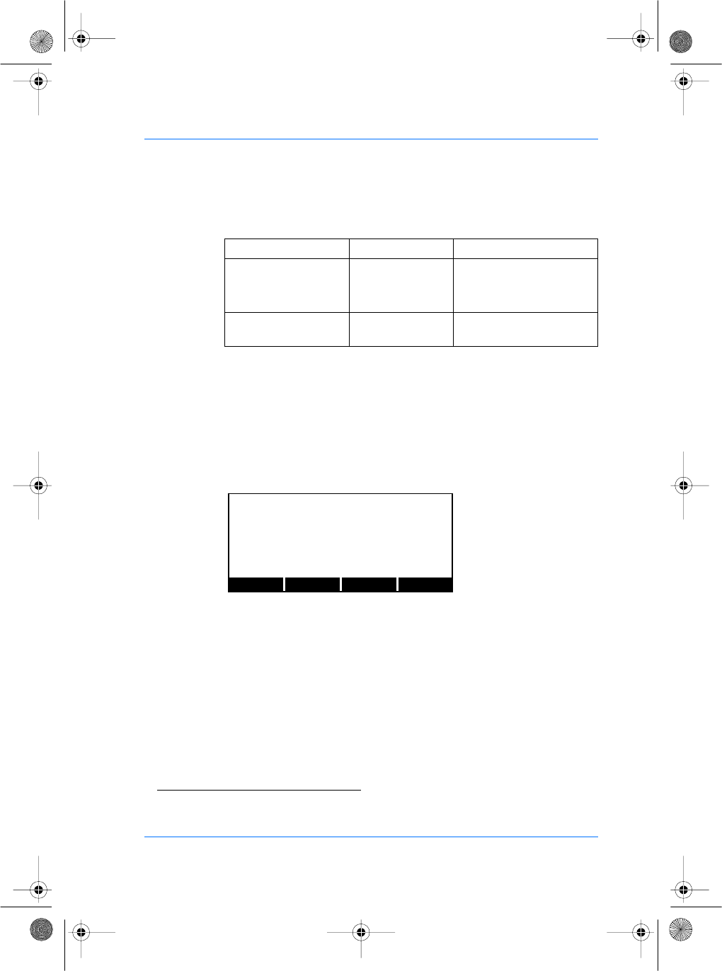
SE32/03-011145-01 SAGEM SA document. Reproduction and disclosure forbidden. 59
E
S
The allowed values are:
Setting up Serial Link Parameters
You can use the serial port(15) to send the corresponding ID to the
central security controller. You can use COM1 or COM2 or both.
Setting up COM1 port
From the System Menu, press the CONFIG key to access the
configuration files. Press the NEXT key until the file menu shows
"/cfg/ Maccess".
Press the EDIT key. Press the NEXT key until the COM1 menu
shows "COM1".
Parameters Value Comment
Send 0 (default value) ID is not sent.
1 ID is sent through the Eth-
ernet port.
IP aaa.bbb.ccc.ddd IP of the central security
controller.
(15)One RS422 port (full duplex, four wires) or one RS232 port.
PREV NEXT EDIT
EXIT
FILE: cfg/Maccess
manuel.book Page 59 Vendredi, 30. mai 2003 12:21 12
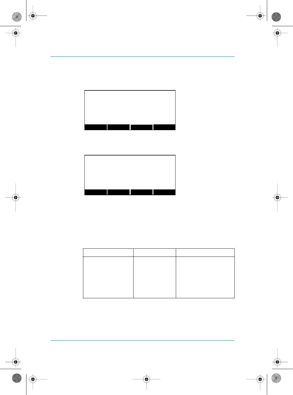
60 SAGEM SA document. Reproduction and disclosure forbidden. SE32/03-011145-01
E
S
Press the EDIT key. You can now edit the format parameters to
select the output format of the ID.
You can now edit the format of the ID. The LEFT and RIGHT keys
move the cursor. The numeric keys enter digits as necessary. The
alphanumeric # key deletes the digit immediately to the left of the
cursor.
The EXIT key aborts editing and restores the previous value.
The allowed values are:
When finished editing, press OK key to update the format of the ID
and return to the previous screen.
Parameters Value Comment
Format 0 (default value) The ID is sent in ASCII for-
mat.
1 The ID is sent in Hexa for-
mat.
2 The ID is sent in BCD(13)
format.
PREV NEXT EDIT
EXIT
FILE: cfg/Maccess
SECTION: COM1
PREV NEXT EDITEXIT
FILE: cfg/Maccess
SECTION: COM1
Format : 0
manuel.book Page 60 Vendredi, 30. mai 2003 12:21 12
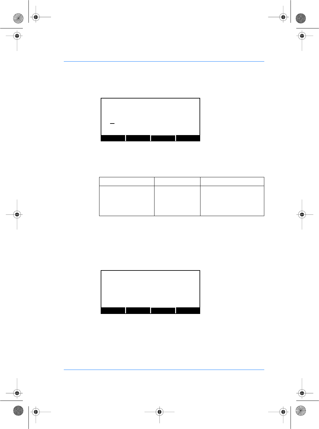
SE32/03-011145-01 SAGEM SA document. Reproduction and disclosure forbidden. 61
E
S
To activate or deactivate the COM1 port, you must select the
SEND key in section COM1.
The allowed values are:
ID transmission on port COM1 is disabled when ILV
communication is activated with key /cfg/Maccess/Admin/Host
Com set to 1.
To configure the COM1 serial link, press the CONFIG key from the
System Menu. Press the NEXT key until the file menu shows "/cfg/
ser0" and select parameters section.
Parameters Value Comment
Send 0 (default value) The COM1 output is not
activated.
1 The output COM1 is acti-
vated.
LEFT RIGHT OK
CANCEL
/cfg/Maccess/COM1
Send
0
PREV NEXT EDIT
EXIT
FILE: /cfg/ser0
manuel.book Page 61 Vendredi, 30. mai 2003 12:21 12
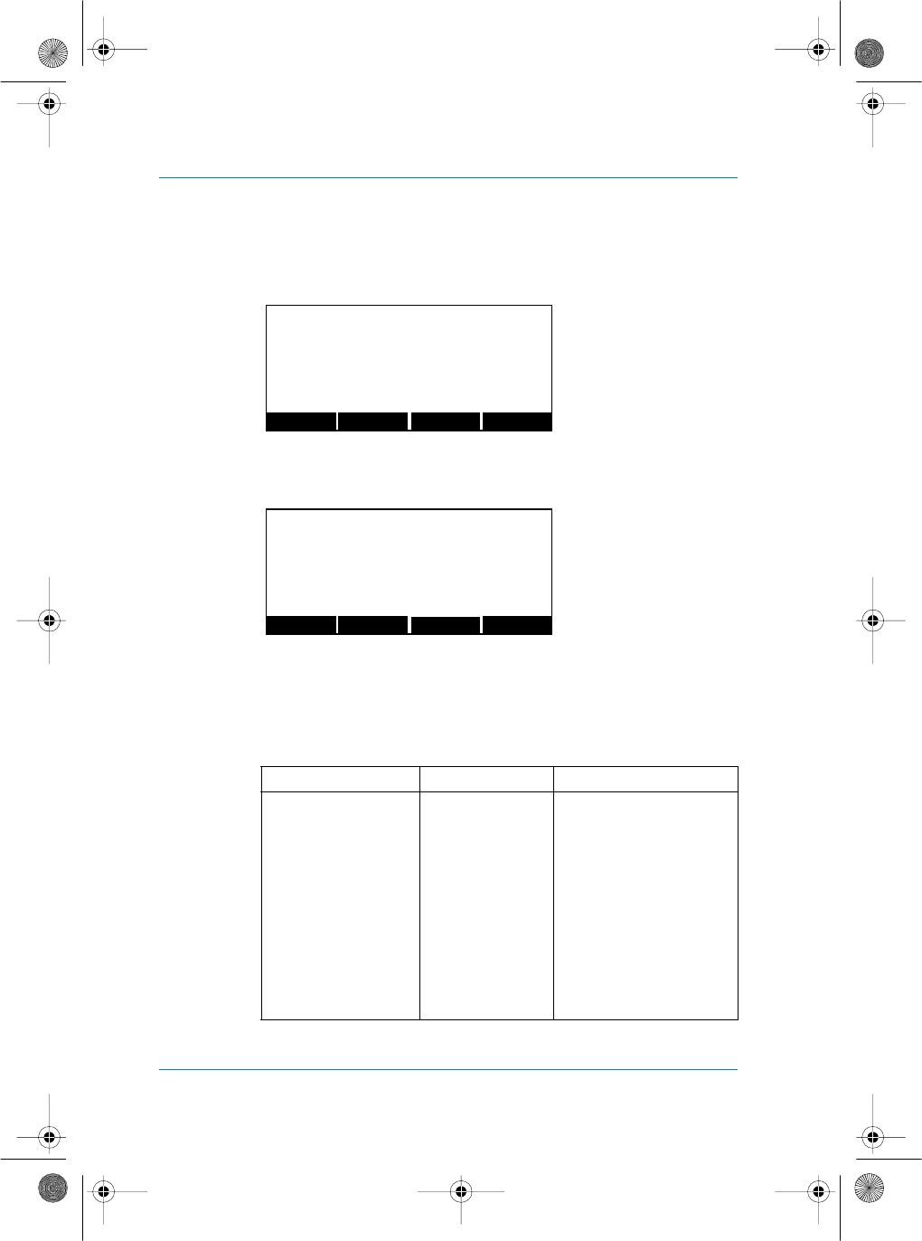
62 SAGEM SA document. Reproduction and disclosure forbidden. SE32/03-011145-01
E
S
Press the EDIT key. The section menu will show "parameters".
Press the EDIT key. You can edit the baudrate value to select the
transmission speed.
You can now modify the baudrate value of COM1 port. The LEFT
and RIGHT keys move the cursor. The numeric keys enter digits as
necessary. The alphanumeric # key deletes the digit immediately
to the left of the cursor. The EXIT key aborts editing and restores
the previous baudrate value.
Parameters Value Comment
Baudrate (bits/second) 0 1200
1 2400
2 4800
3 (default value) 9600
4 19200
5 28800
6 38400
7 57600
8 115200
PREV NEXT EDIT
EXIT
FILE: cfg/ser0
SECTION: parameters
PREV NEXT EDIT
EXIT
FILE: cfg/ser0
SECTION: parameters
baudrate : 3
manuel.book Page 62 Vendredi, 30. mai 2003 12:21 12
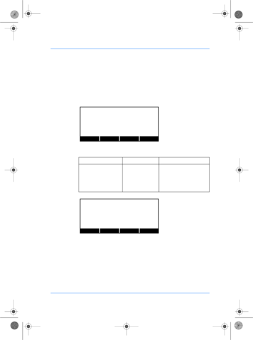
SE32/03-011145-01 SAGEM SA document. Reproduction and disclosure forbidden. 63
E
S
When finished editing, press OK key to update the baudrate field
and return to the previous screen.
To configure the next parameters (databits, parity and control flow),
select the NEXT key to select the other value and follow the
previous descriptions to modify the values.
You can edit the databits parameters. The different values are:
Parameters Value Comment
Databits 5 5
66
7 (default value) 7
88
PREV NEXT EDIT
EXIT
FILE: cfg/ser0
SECTION: parameters
databits : 7
PREV NEXT EDIT
EXIT
FILE: cfg/ser0
SECTION: parameters
stopbits : 2
manuel.book Page 63 Vendredi, 30. mai 2003 12:21 12
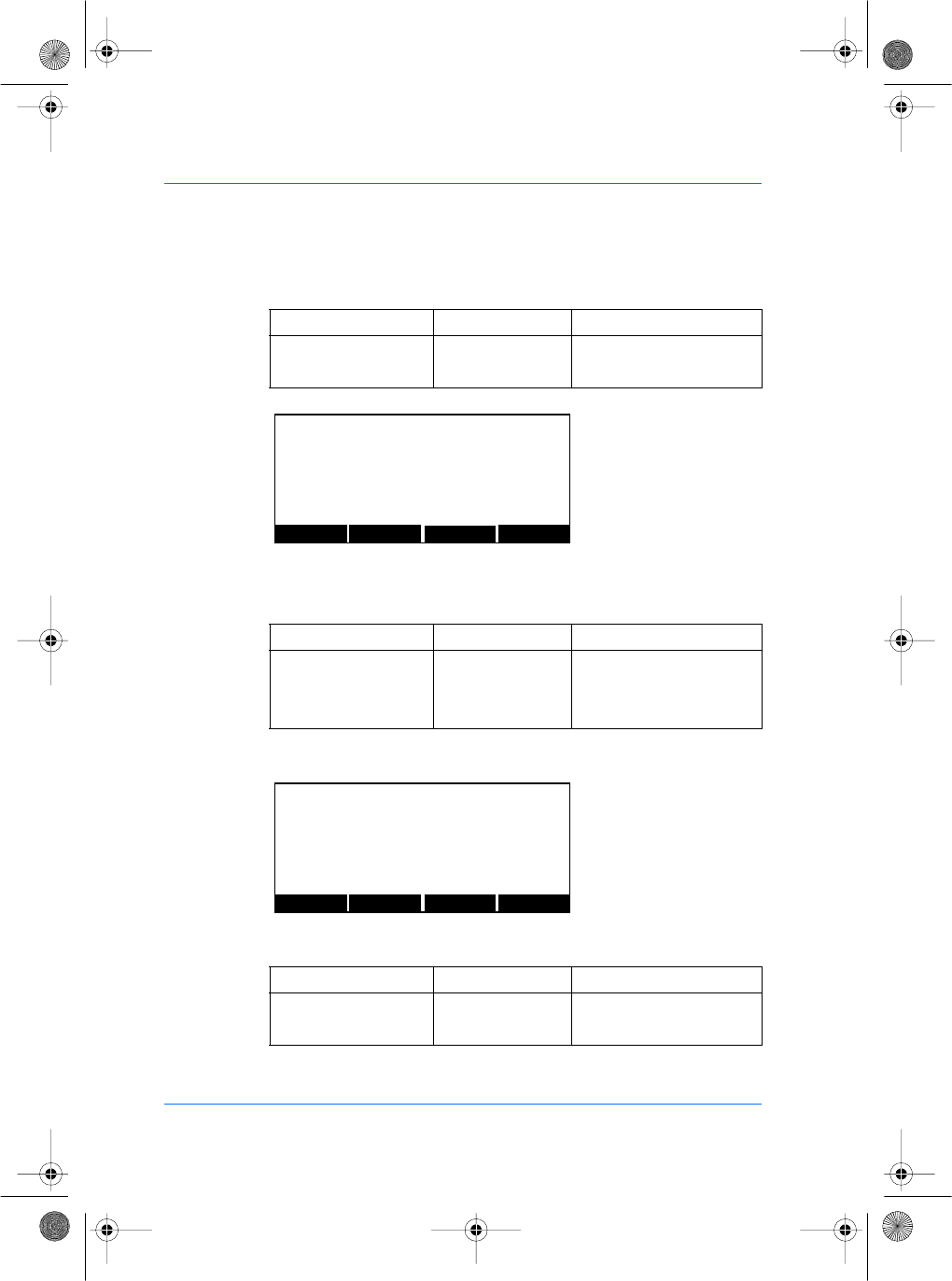
64 SAGEM SA document. Reproduction and disclosure forbidden. SE32/03-011145-01
E
S
You can edit the stopbits parameter, the allowed values are:
You can edit the parity parameter.
The allowed values are:
You can edit the control flow parameter.
The allowed values are:
Parameters Value Comment
Stopbits 1 1
2 (default value) 2
Parameters Value Comment
Parity 0 No
1Odd
2 (default value) Even
Parameters Value Comment
Flow Ctrl Type 0 (default value) No
2 Xon/Xoff
PREV NEXT EDIT
EXIT
FILE: cfg/ser0
SECTION: parameters
Parity : 2
PREV NEXT EDIT
EXIT
FILE: cfg/ser0
SECTION: parameters
flow ctrl : 0
manuel.book Page 64 Vendredi, 30. mai 2003 12:21 12
SE32/03-011145-01 SAGEM SA document. Reproduction and disclosure forbidden. 65
E
S
When using the Deister contacless card reader, COM1 parameters
should be:
Setting up COM2 port
To activate this port, press the CONFIG key to access the
configuration files. Press the NEXT key until the file menu shows
"/cfg/Maccess". Press the EDIT key, and select the RS232 section.
The values are:
Baudrate
Databits
Stopbits
Parity
Flow ctrl
3 (9600)
8
1
0
0
Parameters Value Comment
Send 0 (default value) The RS232 output is not
activated.
1 The RS232 output is acti-
vated.
Format 0 (default value) The ID is sent in ASCII for-
mat.
1 The ID is sent in Hexa for-
mat.
2 The ID is sent is BCD(1)
format.
(1) BCD: Binary Code Decimal
PREV NEXT EDITEXIT
FILE: cfg/Maccess
SECTION: COM2
manuel.book Page 65 Vendredi, 30. mai 2003 12:21 12
66 SAGEM SA document. Reproduction and disclosure forbidden. SE32/03-011145-01
E
S
The following table describes the parameters for the serial link
configuration. Press the CONFIG key to access the configuration
files. Press the NEXT key until the file menu shows "/cfg/ser1" and
select parameters section.
ID transmission on port COM2 is disabled when ILV
communication is activated with the key /cfg/Maccess/Admin/Host
Com set to 2.
The values are described below:
Parameters Value Comment
Baudrate 0 1200 bit/second
1 2400 bit/second
2 4800 bit/second
3 (default value) 9600 bit/second
4 19200 bit/second
5 28800 bit/second
6 38400 bit/second
7 57600 bit/second
8 115200 bit/second
Data bits 5 5
66
7 (default value) 7
88
Stop bits 1 1
22
PREV NEXT EDIT
EXIT
FILE: cfg/ser1
SECTION: parameters
manuel.book Page 66 Vendredi, 30. mai 2003 12:21 12
SE32/03-011145-01 SAGEM SA document. Reproduction and disclosure forbidden. 67
E
S
Setting up Relay Parameters
It is possible to configure the release time of the relay. For this,
from the System Menu, press the CONFIG key to access the
configuration files. Press the NEXT key until the file menu shows
"/cfg/Maccess".
Press the EDIT key, and press NEXT key to select the Relay
section.
Press the EDIT key. You can edit the release time value by 100 ms
steps.
You can now modify the release time value by pressing the EDIT
key.
The LEFT and RIGHT keys move the cursor. The numeric keys
enter digits as necessary. The alphanumeric # key deletes the digit
immediately to the left of the cursor. The EXIT key aborts editing
and restores the previous value.
Parameters Value Comment
Parity 0 No
1Odd
2 (default value) Even
Flow control type 0 (default value)l No
1 Hardware (CTS/RTS)
2 Software (XON/XOFF)
PREV NEXT EDITEXIT
FILE: cfg/Maccess
SECTION: Relay
PREV NEXT EDIT
EXIT
FILE: cfg/Maccess
SECTION: Relay
Time in 100 ms : 30
manuel.book Page 67 Vendredi, 30. mai 2003 12:21 12
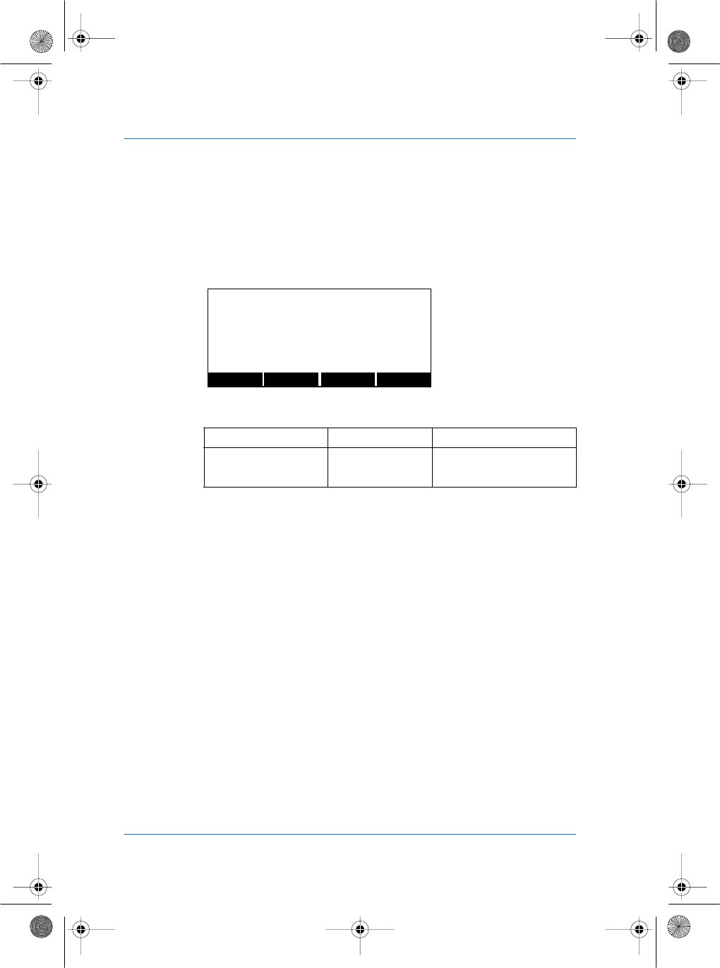
68 SAGEM SA document. Reproduction and disclosure forbidden. SE32/03-011145-01
E
S
When finished editing, press the OK key to update the release
time field and return to the previous screen.
To configure the next parameter, select the NEXT key. You can edit
the "active" value.
The different values are:
Parameters Value Comment
Active 0 (default value) Relay not active.
2 Relay active.
PREV NEXT EDIT
EXIT
FILE: cfg/Maccess
SECTION: Relay
Active : 0
manuel.book Page 68 Vendredi, 30. mai 2003 12:21 12
SE32/03-011145-01 SAGEM SA document. Reproduction and disclosure forbidden. 69
E
S
The VERSION menu
Information Display
From the System Menu, press the VERSION key to access the
information file.
This display contains information that may be necessary if the
SAGEM SA MorphoAccess™ requires technical support. It should
not normally be necessary to access this display unless requested
by SAGEM SA technical support personnel.
Kernel is the name of the module being displayed.
Rev is the revision of the module.
P/N is the part number for the module.
∑ is the checksum for the module.
The next line shows the date of the module’s creation.
ID is the ID for the module in the system.
The PREV and NEXT buttons allow you to browse for all modules
present in your SAGEM SA MorphoAccess™.
EXIT returns to main menu.
PREV NEXT EXIT
Kernel Rev: 3.1
P/N:233082036 ∑:0125B463
May 1 2002 13:21:05 ID:0001
manuel.book Page 69 Vendredi, 30. mai 2003 12:21 12
70 SAGEM SA document. Reproduction and disclosure forbidden. SE32/03-011145-01
E
S
The SERIAL NUMBER menu
Serial Number Display
From the System Menu, press the SER NB key to display the
serial number.
Serial # is your SAGEM SA MorphoAccess™’s serial number.
MicroBoot revision is the revision number of your SAGEM SA
MorphoAccess™’s MicroBoot. This revision number may be
needed when requesting technical support.
ETH is the physical Ethernet address, also known as the MAC
address. This address may be required by your network
Administrator.
OK
Serial # : 993000001
Micro Boot revision : 2.4
ETH : 00:90:27:9A:F2:53
manuel.book Page 70 Vendredi, 30. mai 2003 12:21 12
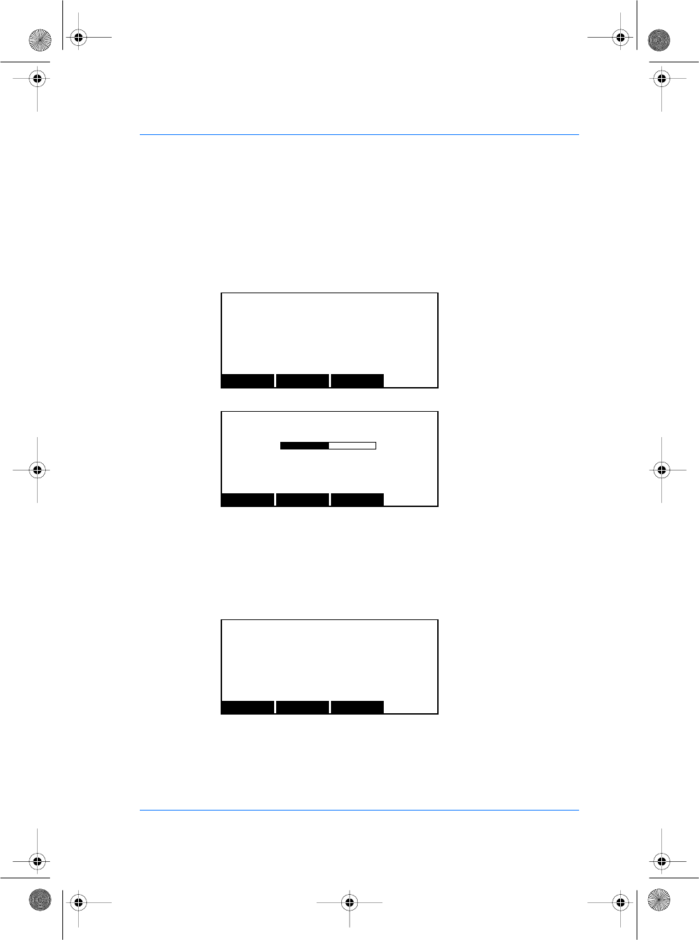
SE32/03-011145-01 SAGEM SA document. Reproduction and disclosure forbidden. 71
E
S
The SETTING menu
Parameters Setting
From the System Menu, press the SETTING key to access the
parameter settings.
The CONTRA selection allows you to adjust the contrast of the
LCD display.
The MORE key increases the contrast, the LESS key decreases
the contrast.
The RTC menu allows you to set the current date and time.
GENERAL SETTINGS
CONTRA RTC EXIT
CONTRAST SETTINGS
LESS MORE EXIT
CONTRAST VALUE : 5
-+
RTC SETTINGS
SETTIME SETDATE EXIT
Time 16:45:44 Date 14/06/00
manuel.book Page 71 Vendredi, 30. mai 2003 12:21 12
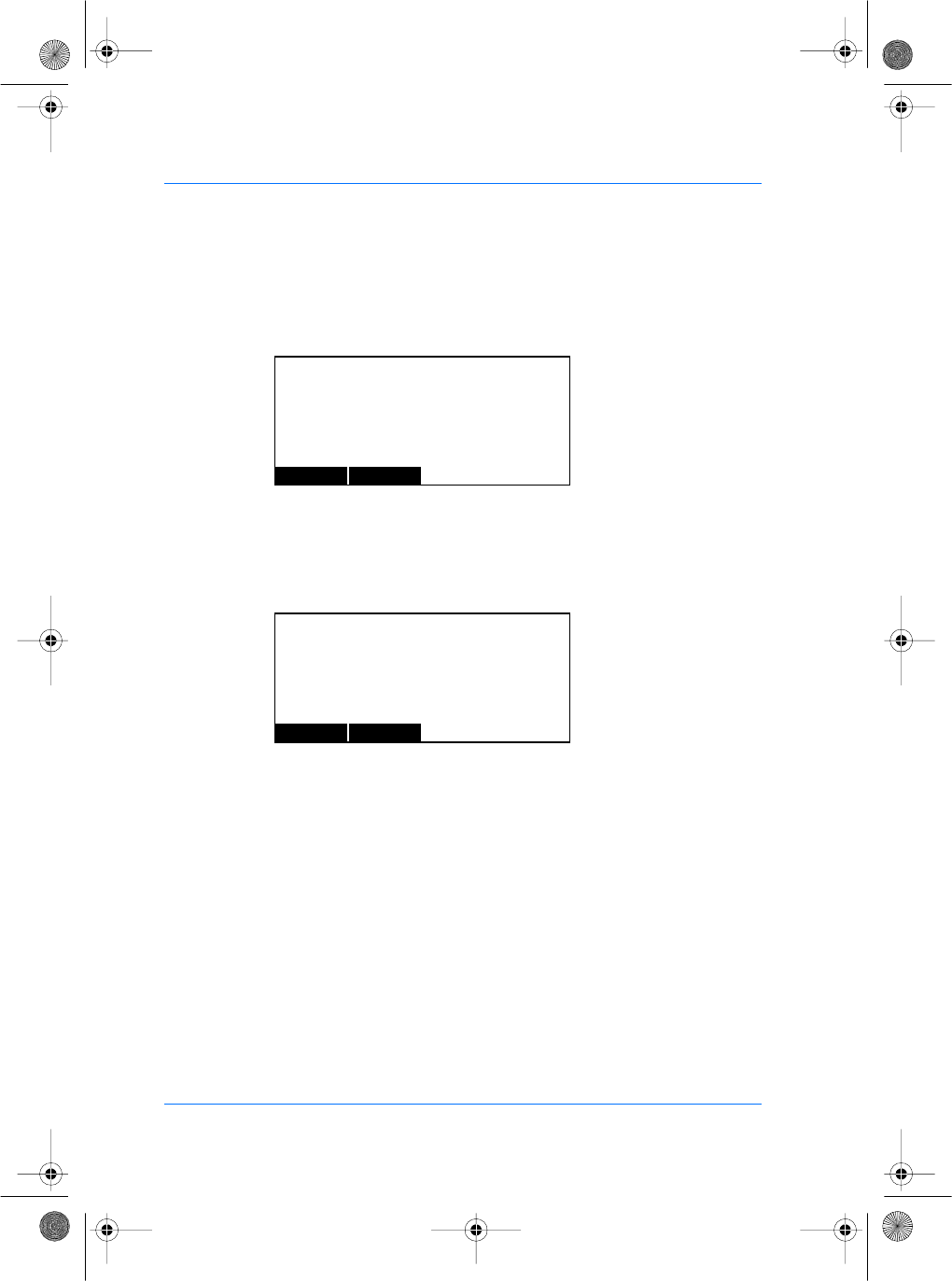
72 SAGEM SA document. Reproduction and disclosure forbidden. SE32/03-011145-01
E
S
The SETTIME key allows you to set the time. Enter the time in the
following format: HHMMSS. The VALID key records your setting.
The CANCEL key aborts editing and returns to the previous menu.
The SETDATE key allows you to set the current date. Enter the
date in the following format: DDMMYY. The VALID key records
your setting.
The CANCEL key aborts editing and returns to the previous menu.
Note : You can use the correction key # to delete the last charac-
ters entered.
TIME SETTINGS
VALID CANCEL
TIME (HHMMSS) : 120000
DATE SETTINGS
VALID CANCEL
DATE (DDMMYY) : 100600
manuel.book Page 72 Vendredi, 30. mai 2003 12:21 12
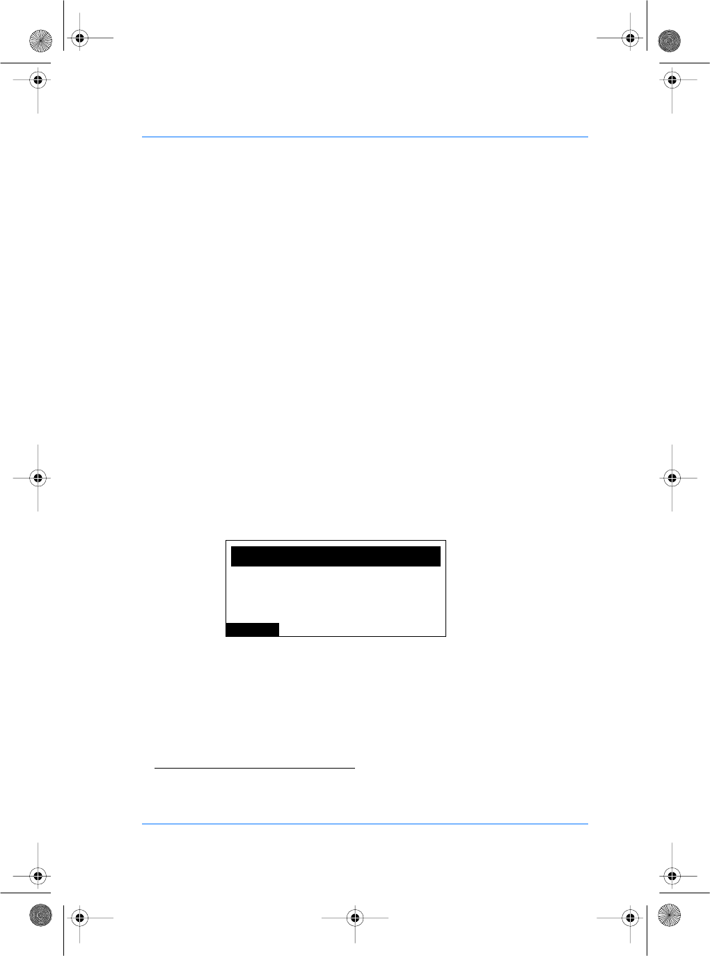
SE32/03-011145-01 SAGEM SA document. Reproduction and disclosure forbidden. 73
E
S
Access the MIFARE keys update menu
(MorphoAccessTM 220)
Each data sector on a MIFARE card is protected in reading and
writing by 2 keys of 6 bytes each. These keys are noted A and B.
Since the card is composed of 16 sectors, there are actually 32
keys.
When you present a MIFARE card to the MorphoAccess for an
authentication, data can be read only if the keys which protect it
are the same as the keys initialized into the reader. By default both
keys A and B are set to 0xFFFFFF for the 16 sectors in the
MIFARE module of the MorphoAccess. These default values are
called Transport keys.
You can change the value of the keys thanks to the hotkey
CL KEYS in the Administrator menu(16). You will need for that an
administrator card containing the new keys to initialize. Please
check the Enrollment Station documentation to know how to create
an administrator card.
While you are in the administrator menu, press the key CL KEYS.
The MIFARE KEYS UPDATE screen appears.
Present the administrator card to start the update.
(16)If you perform this operation, the old user cards won't be readable anymore, since the keys won't be com-
pliant anymore.
CANCEL
MIFARE KEYS UPDATE
Please Present Admin Card
<Current Keys : Transport>
manuel.book Page 73 Vendredi, 30. mai 2003 12:21 12
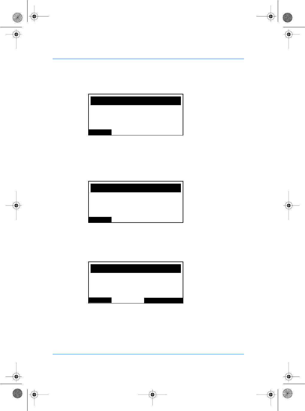
74 SAGEM SA document. Reproduction and disclosure forbidden. SE32/03-011145-01
E
S
When the MorphoAccess™ finishes to update the keys for the
16 sectors, a successful message appears. The keys status
indicates now "user" keys, meaning keys different from 0xFFFFFF
have been loaded into the reader. Then the MorphoAccess™
comes back to the administrator menu after 2 seconds.
If for some reasons the update is not successful (power shutdown
before the end of the operation for instance), a new hotkey will be
available the next time you will enter in the CL KEYS menu. The
keys status will indicate "INVALID" keys.
Pressing the LOAD DFLT KEYS hotkey will allow you to re-update
the 32 keys with the default value 0xFFFFFF.
CANCEL
MIFARE KEYS UPDATE
Updating Key A3 & B3
<Current Keys : UPDATING>
CANCEL
MIFARE KEYS UPDATE
Keys have been udpated !
<Current Keys : USER>
PREV
MIFARE KEYS UPDATE
Please Present Admin Card
<Current Keys : INVALID>
LOAD DFLT KEYS
manuel.book Page 74 Vendredi, 30. mai 2003 12:21 12

44 75
Communication protocol
The communication protocol available allows the terminal to
send commands to a host through the communication
COM1/RS485.
All the commands will be formatted with an "Identier Length
Value" structure as described below:
Identier Length Value
Identier called I This is the identier of the command.
Length called L This is the length of the Value eld in bytes.
Value called V The parameters or data.
The commands will be encapsulated in a packet structure
described on the next gure.
STX ID RC ILV CRC DLE ETX
CRC : Compliance CRC16 V41
Fields name Denition Value
<STX> Start Text 0x02
<ID> Packet Identier 0xE1
<RC> Request Counter Unused byte
<ILV> Identier Length
Data (DLE data
bytes arestuffed)
I:
0x00 for ASCII
0x01 for Hexa
0x02 for BCD
L: 2 bytes
V: Value of identier
<CRC> Transmission error
control
Depends on the
frame
<DLE> 0x1B
<ETX> End Text 0x03
Communication protocol
76
Appendix 1 - Wiegand data format
The 26 bits of transmission consists of two parity bits and 24
code bits. The eight rst code bits are encoding the facility code.
This code identies each Morphoccess in a network. The 16
other bits are data bits. The rst bit transmitted is the rst parity
bit. It is even parity calculated over the rst 12 bits. The last bit
transmitted is the second parity bit. It is odd parity bit calculated
over the last 12 code bits.
Even parity (1 bit) Facility code (8
bits)
Data (16 bits) Odd parity (1 bit)
Compliant with access control 26-Bit - Wiegand reader interface
standard 03/1995.
Appendix 1

46 77
Appendix 2 - ISO 7811/2-1995 - Track 2 Data clock format
Compliant with ISO07811/2-1995 - Track 2.
Data encoding table
Value Bit pattern Meaning
0 0 0 0 0-1 "0"
1 1 0 0 0-0 "1"
2 0 1 0 0-0 "2"
3 1 1 0 0-1 "3"
4 0 0 1 0-0 "4"
5 1 0 1 0-1 "5"
6 0 1 1 0-1 "6"
7 1 1 1 0-0 "7"
8 0 0 0 1-0 "8"
9 1 0 0 1-1 "9"
10 (Ahex) 0 1 0 1-1 unused character
11 (Bhex) 1 1 0 1-0 start sentinel (start character)
12 (Chex) 0 0 1 1-1 unused character
13 (Dhex) 1 0 1 1-0 eld separator
14 (Ehex) 0 1 1 1-0 unused character
15 (Fhex) 1 1 1 1-1 end sentinel (stop character)
The least signicant bit of every digit is sent rst; the fth bit is
an odd parity bit for each group of four data bits.
The complete message always looks as follows:
left
edge
start data
characters
end LRC right
edge
The LRC is calculated by the following procedure: each of the
4 bits in the LRC character is an even parity bit of the equivalent
bits in the telegram including start and stop sentinel.
The fth bit is the odd parity of the four LRC bits (it is not
calculated over all the parity bits).
Appendix 2
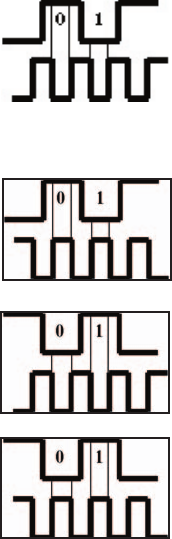
78
Data clock levels
In normal operation mode (default) in and out signals are dened
as:
data
strobe
Other modes are (only for output):
data
inverted strobe
inverted data
strobe
inverted data
inverted strobe
Appendix 2

48 79Appendix 3
Appendix 3 - Reserved conguration values
These values are for internal use only.
For proper operation, these settings should not be changed.
/cfg/lcd0/display/type : 1
/cfg/lcd0/contrast/value : 0
/cfg/ser0/mode/connection: EXT
/cfg/ser0/mode/mode: 450
db/seq ash/start: 0
/cfg/bio/video/channel: 0
/cfg/bio/video/rotation: 0
/cfg/lic/licences/*
80
MORPHO® BRAND BIOMETRIC PRODUCT
WARRANTY, LIMITATIONS, AND SOFTWARE
LICENSE
1. LIMITED WARRANTY AND MAINTENANCE. Subject to the Disclaimers and
Limitations of Warranty set forth below, SAGEM MORPHO, Inc., (hereinafter “SMI,” or
its licensed reseller, as may be applicable) provide the following limited warranty, for the
benet of original Customer only, that all hardware components of the Morpho® brand
biometric product with which this information is associated will conform to the applicable
hardware product specications as published by SMI and will be in good working order
and free from material defects in materials or workmanship, given Customer’s normal
use and service (the “Hardware Limited Warranty”). It is further warranted that the
Morpho® brand biometric software provided with, and/or loaded into and resident in
the biometric product will conform to the applicable software specications or SMI
documentation published by SMI, given Customer’s normal use and operation (the
“Software Limited Warranty”). Any and all third party software programs supplied
with the biometric product are subject to their respective manufacturer’s warranty and
license terms only, and SMI assumes no responsibility for such software.
The Hardware Limited Warranty extends for one (1) year from the date of Customer’s
receipt of delivery of the biometric product. The Software Limited Warranty extends for
ninety (90) days from the date of Customer’s receipt of delivery of the biometric product.
During the duration of the Hardware and Software Limited Warranties, the rst level
of support shall be provided by telephone “Help Desk” support (the applicable Help
Desk telephone number is included with the packaged biometric product). Hardware
repairs which cannot be remedied through Help Desk consultation shall be made by
returning the hardware component to an authorized SMI service depot, in accordance
with instructions issued by the service depot, at Customer’s expense. Return delivery
of the repaired or replaced component shall be at SMI’s expense. SMI shall repair
or replace any nonconforming hardware component at its sole election. Software
problems not remedied through Help Desk consultation may be corrected through
software patches or updates issued by SMI or by replacement of the unit in which the
software is resident, at SMI’s sole election. The Limited Software Warranty does not
entitle the customer to automatically receive patches, updates or other notication of
software correction or revision during the duration of the warranty. The original warranty
periods shall not be renewed or extended by subsequent repair or replacement.
Biometric product maintenance after expiration of the one (1) year warranty may be
available pursuant to the terms and conditions of a separate Maintenance Agreement
– please contact the location from which the biometric product was purchased for
further details.
Warranty
50 81
2. LIMITATIONS AND DISCLAIMERS OF WARRANTY.
SMI does not warrant that operation of the biometric product will be
uninterrupted or error-free; further, no biometric product or system can be guaranteed
to be 100% accurate, or to properly enroll, identify, or authenticate every individual.
SMI shall have no responsibility for repairing or otherwise remedying any defect or
nonconformity in the condition or operation of the biometric product or its software if: 1)
modications to Customer’s site are necessary for proper operation, and Customer’s
site preparation is inadequate; 2) the biometric product is not professionally installed
in accordance with applicable industry standards, local building/zoning codes such as
the National Electric Code, and proper installation practices; 3) the biometric product
is not maintained and operated with all proper accessories under normal conditions
by competent personnel; 4) the biometric product incorporates replacement parts
not authorized by SMI; 5) the biometric product has been subjected to disassembly
except as required for normal installation, modication beyond what is described in
SMI-supplied installation and operation guides, unauthorized enhancement, abuse
or misuse; or 6) the defect or nonconformity has not been reported to the designated
Help Desk within ten (10) days of its discovery by Customer. As Customer’s sole
and exclusive remedy for any nonconformity or defect in the condition or operation of
the biometric product for which SMI is responsible, SMI shall provide its reasonable
efforts to remedy same as set forth in Section 1, above during the applicable stated
Limited Warranty Period. With the exception of its Limited Warranties set forth in
Section 1, above, TO THE MAXIMUM EXTENT ALLOWED BY APPLICABLE
LAW, SMI DISCLAIMS ANY AND ALL PROMISES, REPRESENTATIONS AND
WARRANTIES, EXPRESS OR IMPLIED, WITH RESPECT TO THE BIOMETRIC
PRODUCT, ITS HARDWARE, SOFTWARE, DESIGN, OR FUNCTIONALITY, OR
ITS MERCHANTABILITY OR FITNESS FOR ANY PARTICULAR PURPOSE, OR
ARISING FROM USAGE OF TRADE, COURSE OF DEALING, OR COURSE
OF PERFORMANCE. SMI FURTHER DISCLAIMS ANY AND ALL PROMISES,
REPRESENTATIONS AND WARRANTIES, EXPRESS OR IMPLIED, WITH
RESPECT TO ANY OF SMI’S SERVICES PERFORMED HEREUNDER.
3. LIMITATIONS OF LIABILITY. The entire liability of SMI to Customer (or to
any person or entity claiming through Customer) for any claim whatsoever related to
the biometric product or the parties’ transaction shall not exceed the total amount of
all payments made for the biometric product by Customer to the date of the claim. IN
NO EVENT SHALL SMI BE LIABLE TO CUSTOMER FOR ANY LOST PROFITS,
LOST INFORMATION, BUSINESS INTERRUPTION, OR OTHER CONSEQUENTIAL,
INCIDENTAL, SPECIAL, PUNITIVE OR INDIRECT DAMAGES (WHETHER IN AN
ACTION IN CONTRACT OR TORT OR BASED ON WARRANTY), EVEN IF SMI HAS
BEEN ADVISED OF THE POSSIBILITY OF SUCH DAMAGES, ARISING OUT OF,
OR RELATED TO, THE BIOMETRIC PRODUCT OR THE PARTIES’ TRANSACTION.
Some jurisdictions do not allow excluding or limiting implied warranties, or limiting
liability for incidental or consequential damages, and some jurisdictions have special
statutory consumer protection provisions that may supersede this limitation. As a
result, the limitations and disclaimers of warranty and liability set forth herein may not
apply to Customer if prohibited by the laws of Customer’s jurisdiction.
Warranty
82
MORPHO® BRAND BIOMETRIC SOFTWARE END-USER
LICENSE
Important - Terms Govern Usage of Software
Please Read Carefully Prior to Commencement of Operations
This SMI End-User License Agreement («License») allows the acquirer of an SMI
biometric product (referred to in the following sections as the «End-User») to use the
proprietary SMI software provided with, and/or loaded into and resident in, the SMI
biometric product, so long as the End-User uses the SMI software strictly in accordance
with the terms and conditions of this License, below. This License is a binding legal
contract between the End-User and SMI, or its licensed reseller (sometimes referred
to hereafter generically as «Licensor»). By using the SMI software provided with,
and/or resident in the SMI biometric product in any way, the End-User agrees to be
bound by the License terms on a continuing basis. If the End-User does not agree to
the terms of this License, Licensor is unwilling to license the software to End-User.
In such event, End-User may not use the software, and End-User should promptly
contact the location from which the SMI Product was acquired for instructions on return
of the unused biometric product for a refund or credit.
1. GRANT OF RIGHTS. The SMI software provided with, and/or loaded into and
resident in, the biometric product, is licensed, not sold, to the End-User by Licensor,
and is protected by United States copyright and trade secret laws, as well as by other
intellectual property laws and international treaties. Licensor grants to the End-User
the right to use the copy of the SMI software originally loaded and resident in each
unit of the SMI biometric product acquired by End-User in object-code format, subject
to the following restrictions. End-User shall not use the SMI software in any computer,
computer system, or hardware conguration other than in the course of authorized
use of the SMI biometric product acquired by End-User. End-User shall not reverse
engineer, decom-pile, disassemble, or copy the SMI software (except, and then only to
the extent that such activity is expressly permitted by applicable law, notwithstanding
this limitation); nor shall End-User modify, create a derivative work, or otherwise use
the SMI software, except as stated in this License. End-User shall not copy the written
materials accompanying the SMI software, without the express written permission of
Licensor. End-User shall not remove, obscure or alter any notice of patent, trademark,
service-mark, copyright, or other proprietary rights related to the SMI software or the
SMI biometric product. End-User shall promptly notify Licensor of any unauthorized
use of the SMI software that comes to End-User’s attention. SMI reserves all rights
not expressly granted to the End-User hereunder.
2. TRANSFERABILITY. End-User may transfer the SMI software to another person
or entity with SMI’s prior written consent, which shall not be unreasonably withheld,
so long as: (1) the SMI software is transferred as an integral part of the SMI biometric
product to be transferred to a third party; (2) the SMI software is in its original format,
without modication (excepting authorized software upgrades installed by SMI, or
its licensed reseller); and (3) End-User transfers all of End-User’s rights under this
License on a permanent basis to the third party recipient AND the recipient agrees to
be bound by all terms of this
Software License
52 83
License as End-User’s assignee. End-User shall not otherwise sublicense, assign,
loan, rent, transfer, give or otherwise dispose of its interest in the SMI software to
others, or vend services to others based directly on the SMI software (e.g., service
bureau activities) unless such is otherwise expressly permitted by the terms of a written
agreement between SMI and End-user.
3. TERMINATION OF LICENSE. End-User acknowledges and agrees that the SMI
Software contains valuable trade secrets and proprietary information which are the
sole property of SMI and that violation of End-User’s license obligations hereunder will
cause SMI and its licensed reseller immediate, irreparable harm for which monetary
damages are inadequate. In such event, SMI and/or its licensed reseller shall be
entitled to seek injunctive and equitable relief, in addition to all other remedies available
under law to prevent any such violation, or to secure enforcement of this License.
Without prejudice to any other rights or remedies, SMI and/or its licensed reseller may
terminate this License immediately in the event End-User fails to comply with the terms
and conditions of this License. In such event, End-User must immediately cease all
use of the SMI software, destroy all copies thereof, and provide certication of such
destruction as may be requested by SMI and/or its licensed reseller.
4. SEVERABILITY; APPLICABLE LAW. If any provision of this Agreement is found
to be unlawful, void or unenforceable, then that provision shall be severed from this
Agreement and will not affect the validity or enforceability of any of the remaining
provisions. This Agreement shall be governed, construed and enforced solely and
exclusively in accordance with the laws of the State of Washington, U.S.A., without
regard to conict of law principles
5. U.S. GOVERNMENT RESTRICTED RIGHTS LEGEND. The SMI software and
any accompanying materials are provided with Restricted Rights. Use, duplication, or
disclosure by the U.S. Government and agencies thereof is subject to restrictions set
forth herein and in subparagraphs (c)(1) and (2) of 48 CFR 52.227-19, Commercial
Computer Software-Restricted Rights, as applicable (or, as applicable, similar
regulatory restrictions on Rights in Technical Data and Computer Software, e.g.,
DOD FAR Supplement 252.227-7013 (c)(1)(ii)). Manufacturer is SAGEM MORPHO,
Inc., 1145 Broadway Plaza, Suite 200, Tacoma, WA 98402.
Software License
