Salus Rxrt505 Instruction Manual ManualsLib Makes It Easy To Find Manuals Online!
2014-12-11
: Salus Salus-Rxrt505-Instruction-Manual-121155 salus-rxrt505-instruction-manual-121155 salus pdf
Open the PDF directly: View PDF ![]() .
.
Page Count: 28

R
RT
5
0
5R
F
5
T
T
T
T
5
5
5
R
R
R
R
R
R
R
R
R
RT
T
F
F
R
R
R
R
5
5
5
5
5
5
5
5
5
5
R
R
R
R
R
R
5
5
RT5
0
05R
F
0
0
5
RT
T
R
R
R
R
R
R
R
F
F
F
5R
R
R
R
R
5
0
0
0
T
T505RF
T
T
T
R
R
R
RF
F
F
0
0
0
5
5
R
RT
5
RT5RT5RT5
RT5
RT5
RT5
RT5
RT5
RT
RT
RT
RT
RT
RT
RT5
5
5
5
5
5
05R
F
F
F
F
F
F
F
F
F
F
5
5
5R
R
R
0
0
0
0
0
0
5
5
5
5
5
5
5
5
5
5
5
5
T
T
T
T
T
T
T
T
T
T
T
T
T
T
T
T
T
T
T
T
T
T
T
T
T
T
T
T
T
T
T
T
T
T
T
T
T
T
T
T
T
T
T
T
T
T
T
T
5
5
0
0
0
0
R
R
R
R
R
R
0
0
0
0
T505RF
T
T
T
T
R
R
R
RF
F
0
0
0
5
5
5
R
R
R
RT
5
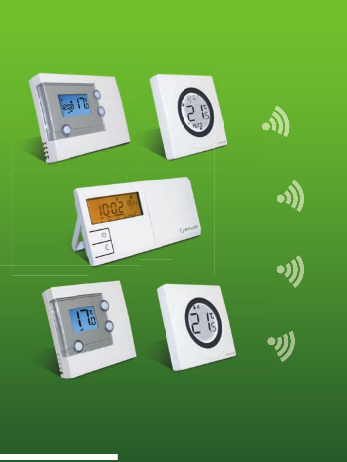
Thermostat Receiver Units
This instruction manual covers the receivers above
886MHz
RXWBC605
R
RT
50
0
5R
F
5
T
T
T
T
5
5
5
R
R
R
R
R
R
R
R
R
R
R
R
R
T
T
F
F
R
R
R
R
5
5
5
5
5
5
5
5
5
R
R
R
R
R
R
5
5
RXST625
RXVBC605
RXRT505
ST325TX
0915FLTX
ST625TX
0915FLT
RT305TX
RT505TX
SUPPLIED SEPERATELY

RXRT5
05
RXWB
C6
0
5
RXVBC605
R
R
X
X
S
S
T
T
6
6
2
2
5
5

PRODUCT COMPLIANCE
This product complies with the essential requirements
of the following EC Directives:
• Electro-Magnetic Compatibility directive 2004/108/EC
• Low Voltage Directive 2006/95/EEC
• EC Marking directive 93/68/EEC
SAFETY INFORMATION
These instructions are applicable to the Salus Controls model
stated on the front cover of this manual only, and must not be
used with any other make or model. These instructions are
intended to apply in the United Kingdom only, and should be
followed along with any other statutory obligations. This
accessory must be fitted by a Competent person, and
installation must comply with the guidance provided in the
current editions of BS7671 (IEE Wiring Regulations) and Part
‘P’ of the Building Regulations. Failure to comply with the
requirements of these publications could lead to prosecution.
When fitting the receiver always isolate the AC Mains supply
before opening or removing the unit from the wall or wall box.
RECEIVER INSTRUCTION MANUAL
4

RT RECEIVER
INTRODUCTION
The RXRT505 is used for the wiring connections and on/off
control. The RXRT505 is linked to your thermostat via radio
frequency (RF) signal.
Features
• LED status indication
• ON / OFF switch
• 868 MHz communication
CONNECTING THE RXRT505 RECEIVER
The RT Receiver should be mounted in a suitable location that is
both accessible for the connection of mains and control wiring,
and allows good reception of the RF signal. The receiver needs a
230V AC mains supply to operate, and this should be fused
appropriately (13A max.). The receiver should be mounted in a
location where it will not come into contact with water, moisture
or condensation.
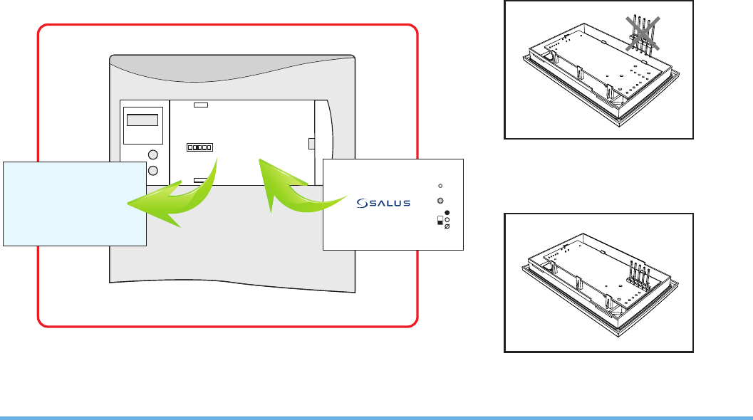
The receiver On/Off switch is accessible from the front face of the
receiver, as shown in this picture:
RXRT505 INSTRUCTION MANUAL 5
On the front cover of the receiver you will
see that there is the On/Off switch and two
Light Emitting diodes (LEDs). The switch
allows you to turn off the receiver if
necessary to prevent it calling for heat. The
top LED (red) will illuminate when the
switch is in the ‘On’ position and the unit is
receiving power. The top LED (green)
illuminates when the receiver is
receiving a heat call transmission from the
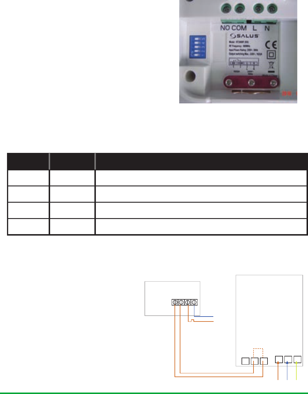
thermostat. The wiring terminals and RF Address Code setting DIP switches
are located on the rear of the receiver, as shown above:
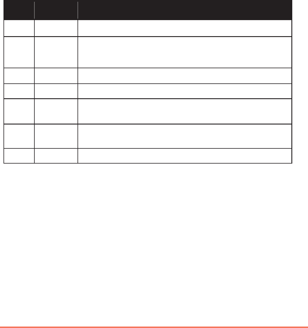
RECEIVER WIRING TERMINALS
Terminal Identifier Description
1 NO Normally Open (N/O) Volt free contacts
2 COM Common terminal (COM) Volt free contacts
3 L Live supply (230V AC)
4 N Neutral
TYPICAL WIRING INSTALLATIONS
The RT receiver is wired the same
way no matter if you are wirings
230V or 24V, the receiver will
always need a 230V Live and
Neutral feed connected into L &
N terminals. The COM and NO is
to be connected to the boilers
external loop (see diagram
below), if connected in this way
the receiver relay can only switch
voltage supplied by the boiler.
RECEIVER BOILER
MAINS
FEED
N
L
N.O. COM L N
Thermostat loop (Remove link)
Live Feed
NL SL LNE
RXRT505 INSTRUCTION MANUAL
6
RXRT505 INSTRUCTION MANUAL 7
SETTING UP RF COMMUNICATION WITH
YOUR THERMOSTAT
RT505TX / RT305TX
After you have switched the receiver on, the
thermostat will automatically pair* with the
RT505TX and the RT305TX (only). When the red
LED stops flashing, the unit has successfully paired.
If you have difficulty in pairing the thermostat, we
recommend changing the address codes in the
thermostat and the receiver.
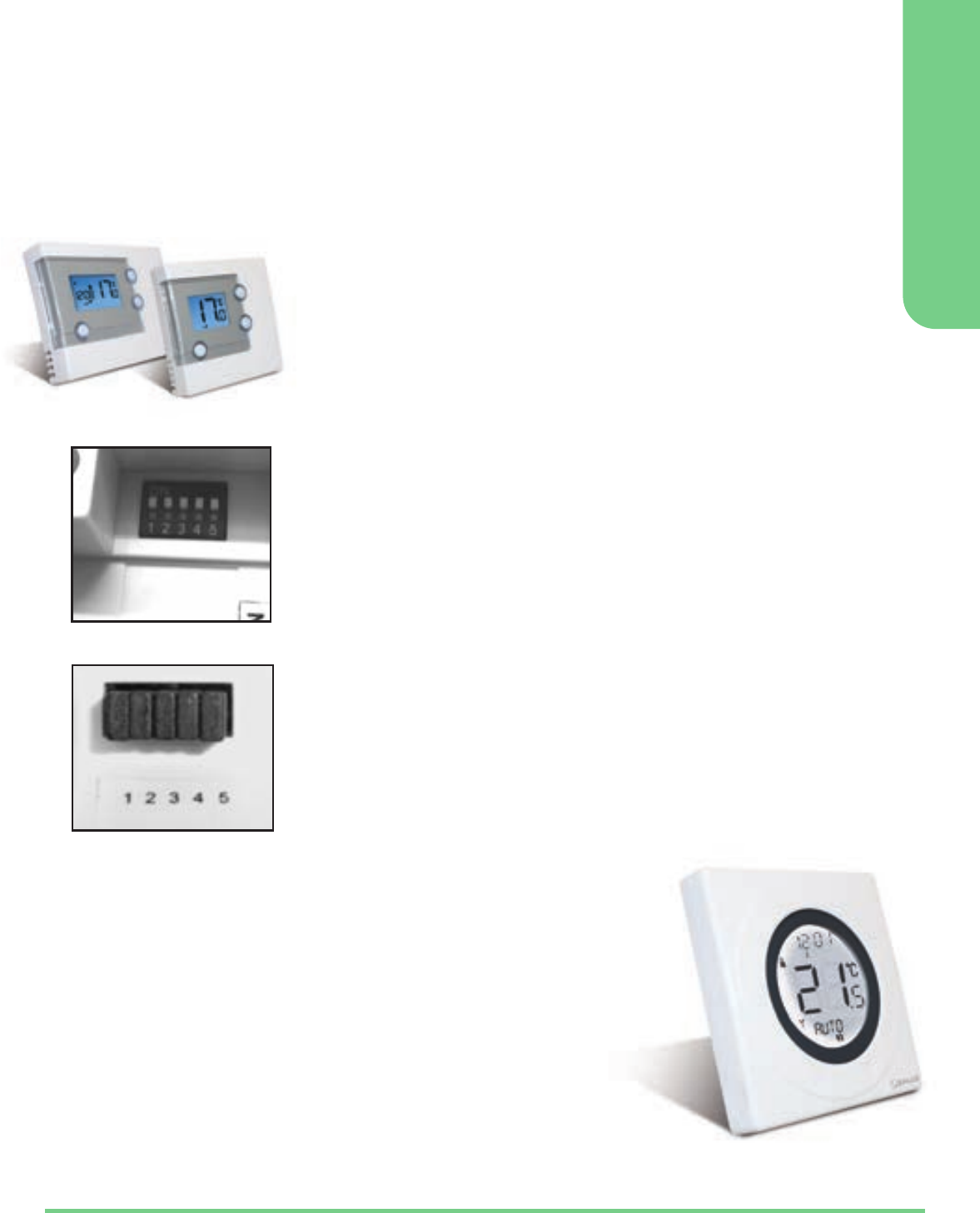
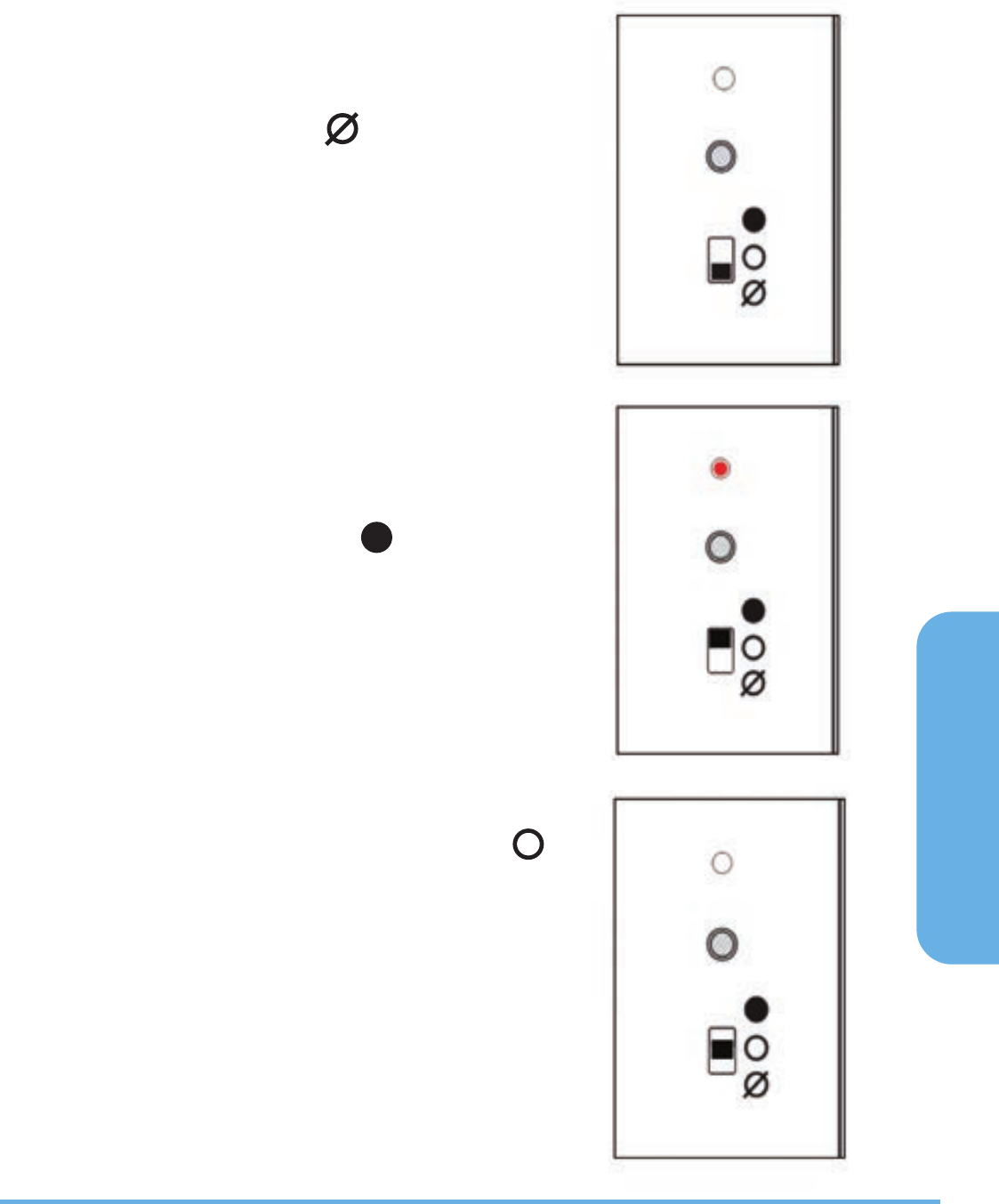
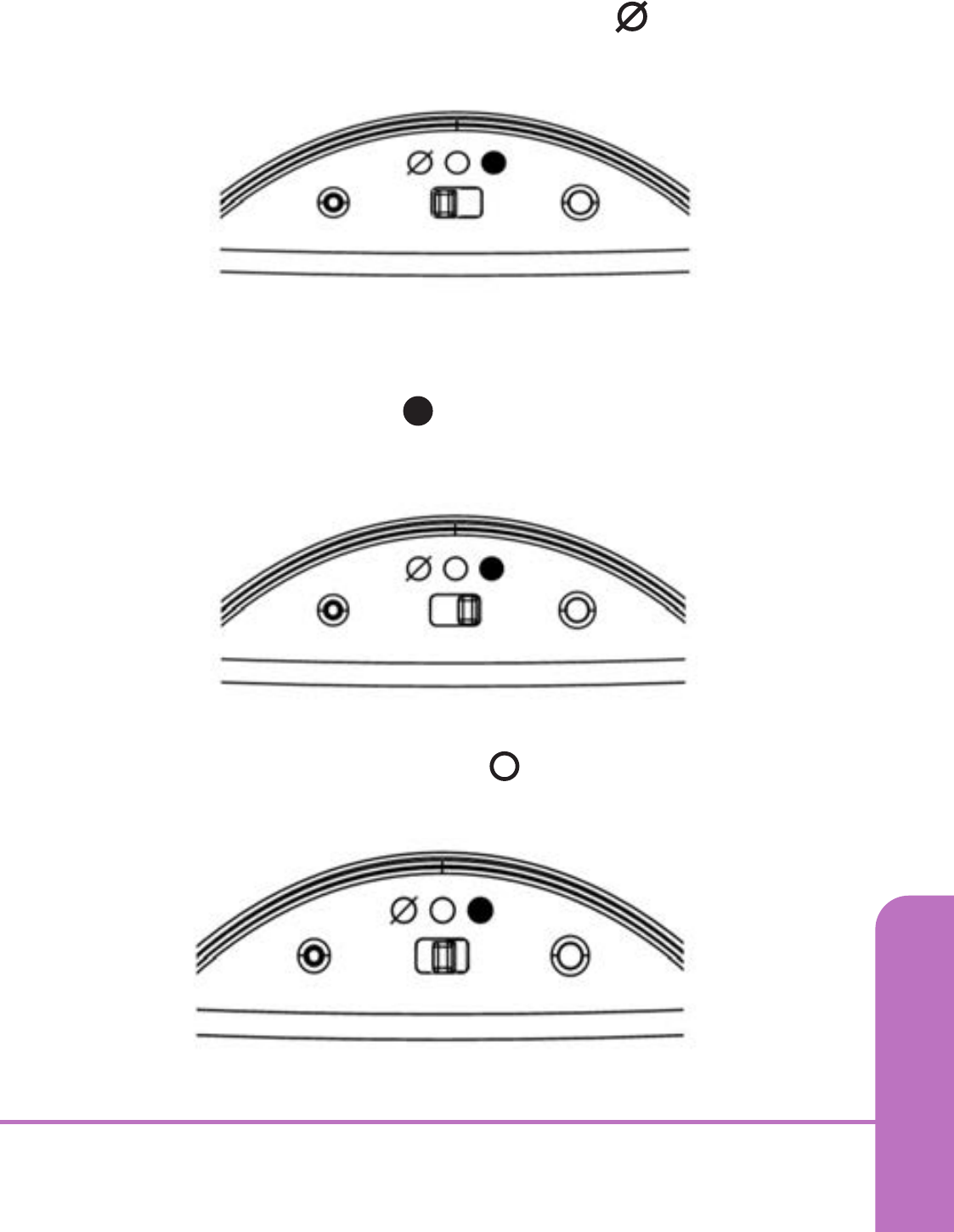
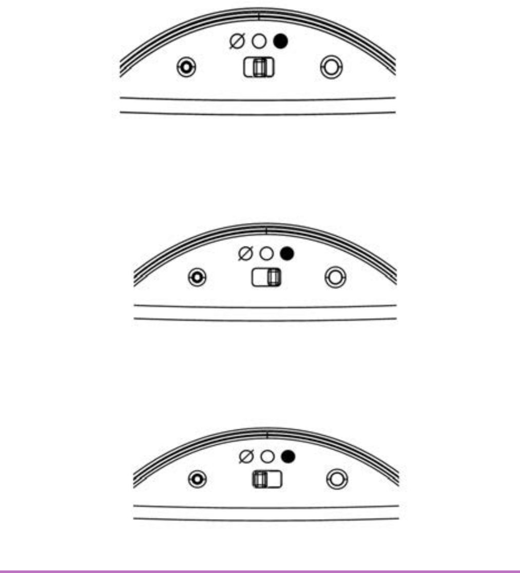
To adjust the RF address code of the receiver,
simply push up one or more of the 5 DIP switch
levers on the DIP switch bank located on the back
of the receiver (the levers are numbered 1 to 5
from bottom to top, as shown in the picture left),
and then make a note of the setting of each switch:
To adjust the RF address code of the thermostat,
remove one or more of the jumper caps located on
the back of the unit (labelled 1,2,3,4 and 5, and
shown in the picture left) so that the jumper
settings match the settings made on the receiver:
DIP Switches
Thermostat
Jumper Caps
ST325TX / ST625TX
1. Switch power on the receiver, the receiver
will now automatically enter pairing mode.
2. Enter Pair Menu on the S-Series thermostat
and start the pairing procedure*.
3. When the red LED on the receiver stops
flashing, pairing has been successful.
* For full instructions on thermostat pairing see:
RT505TX Manual - Page 13 ST325TX Manual - Page 15
RT305TX Manual - Page 9 ST625TX Manual - Page 11

S-SERIES RECEIVERS
INTRODUCTION
The RXST625 is used for the wiring connections and on/off
control. The RXST625 is linked to your thermostat via radio
frequency (RF) signal.
Features
• LED status indication
• Manual override
• 868 MHz communication
CONNECTING THE RXST625 RECEIVER
The RT receiver should be mounted in a suitable location that is
both accessible for the connection of mains and control wiring,
and allows good reception of the RF signal. The receiver needs a
230V AC mains supply to operate, and this should be fused
appropriately (13A max.). The receiver should be mounted in a
location where it will not come into contact with water, moisture
or condensation.
RXST625 INSTRUCTION MANUAL
8
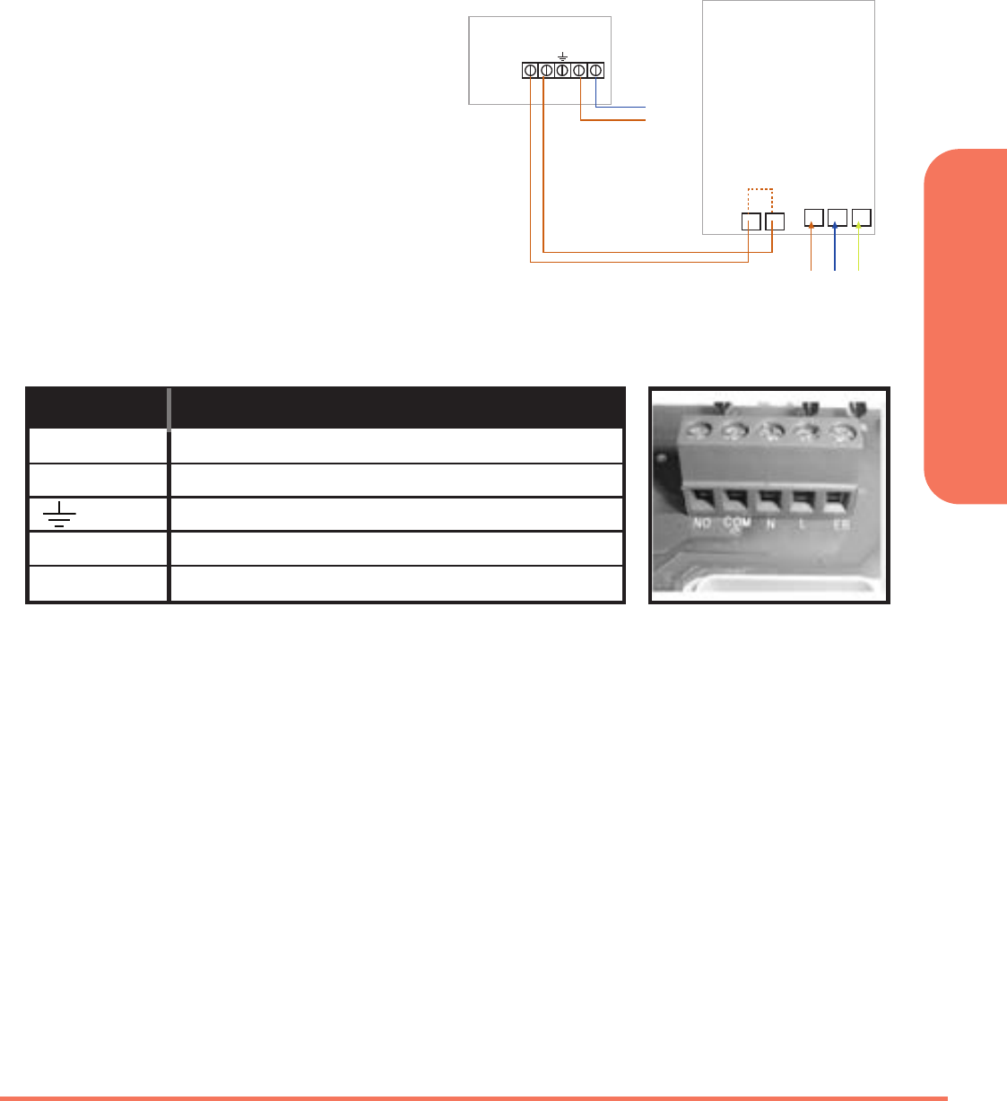
TYPICAL WIRING INSTALLATIONS
The RXST625 receiver is wired the
same way no matter if you are
wirings 240V or 24V, the receiver
will always need a 240V Live and
Neutral feed connected into L & N
terminals. The COM and NO is to
be connected to the boilers
External Loop (see diagram
below), if connected in this way
the receiver relay can only switch
voltage supplied by the boiler.
SETTING UP RF COMMUNICATION:
Ensure that the slide switches are in AUTO and ON positions and then press
the sync button. Press and hold the SYNC button for at least 3 seconds,
then release. The receiver will now enter pairing mode, the green LED will
now turn red to indicate that the receiver is ready to pair with the
thermostat*.
While the signal is being received, the red LED will stay on until the pairing
is successful, when pairing is successfull the red LED will turn green.
* For full instructions on thermostat pairing see:
RT505TX Manual - Page 13 ST325TX Manual - Page 15
RT305TX Manual - Page 9 ST625TX Manual - Page 11
RECEIVER BOILER
MAINS
FEED
N
L
Thermostat loop (Remove link)
Live Feed
LSL LNE
COM N/O L N
RXST625 INSTRUCTION MANUAL 9
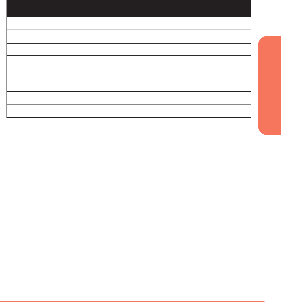
These electrical connections are shown in the table below:
Terminal Function
COM Common Contact (volt free input)
NO Normally Open Contact (volt free output)
Earth Parking (No electrical connection)
L Incoming Mains - Live
N Incoming Mains - Neutral
RECEIVER LED INDICATORS
The LED indicators on the RXST625 receiver are designed to give a clear
and easily understood indication of the current state of the system. The
various LED signal combinations and descriptions of what they indicate
are shown in the table below:
LED State Indication
Blue On Receiver is in manual mode and system is calling for heat.
Blue Flashing Receiver is in automatic mode and system is calling for heat.
once per
second
Blue Off Receiver is in automatic mode and system is NOT calling for heat
Green On Power is on
Green Flashing for Receiver has received correct RF address and command signal
4 seconds
Red On and Receiver is either receiving a new RF address code in SYNC mode,
flashing or has failed to store the new RF address code when in SYNC mode
Yellow On Receiver is in failsafe mode after no RF signal received for over 1 hour
RXST625 INSTRUCTION MANUAL
10
The status of the RXST625 receiver is indicated by the use of two bi-
colour Light Emitting Diodes (LEDs). The status indicators are:
USER CONTROL FUNCTION SUMMARY
Key/Operation Functions
Auto Sets receiver to Automatic mode (default setting)
Manual Sets receiver to Manual mode
On Turns relay output ON (default setting)
Cycle Switches receiver output on and off in a 15 minute cycle
(4 minutes on, 11 minutes off)
Off Turns relay output OFF
SYNC Button Enables RF signal synchronisation with RXST625 thermostat
Reset Button Resets the receiver to default (original factory) settings
RECEIVER MODES
The RF receiver can operate in three different modes – AUTO or
MANUAL, and also has a FAILSAFE mode of operation. These modes are
selected by using the slide switches on the front of the receiver:
AUTO MODE
Moving the slide switch to the ‘AUTO’ position selects the Automatic
operation mode of the RF receiver In this mode, the receiver will
automatically receive an RF signal from the thermostat and control the
output relay. When in auto mode, if RF communication between the
receiver and thermostat is lost for less than one hour, the receiver
remains in the same operating state it was in when the signal was lost.
If the RF signal is lost for more than one hour, the receiver will enter
Failsafe mode, and control of the receiver output will be based on the
setting of the Failsafe mode switch. Please be aware that if the
thermostat is operating in Service mode when changing the receiver
switch position, the relay output may be affected.
RXST625 INSTRUCTION MANUAL 11

MANUAL MODE
Moving the slide switch to the ‘MANUAL’ position selects the manual
operation mode of the RF receiver. In manual mode, the receiver
ignores the RF signal from the thermostat and controls the output relay
manually, based on the setting of the failsafe mode switch.
FAILSAFE MODES
Failsafe mode has three user selectable settings – ‘ON’, ‘CYCLE’ and
‘OFF’. With the failsafe switch in the ON position, the output relay will
be turned on, in the OFF position the output relay will be turned off,
and in the CYCLE position the output relay will be operated according
to a preset time sequence (on for 4 minutes and off for 11 minutes).
When operating in failsafe mode, the LEDs will indicate the receiver
relay status as follows:
Mode LEDs Indication
On Blue and Yellow Each LED lights alternately,
approx. once per second
Off Yellow On
Cycle Blue On for 4 minutes,
off for 11 minutes
If required the user can switch to another mode without having to reset
the controller; for instance you can switch from auto mode to manual
mode with the output relay being controlled accordingly. To illustrate
this point, even when switched into manual mode the receiver can still
receive the RF signal from the thermostat and once the user switches to
auto mode, the output relay will be controlled to turn on or turn off
automatically once more.
RXST625 INSTRUCTION MANUAL
12

RXVBC605 RECEIVER
INTRODUCTION
The RXVBC605 is an integral plug-in RF boiler control. The RF
boiler control is a direct replacement for the basic time clock or
blanking plate usually supplied with the boiler. Installing the RF
boiler control takes minutes. Once installed, you will benefit
from all the control features of the Salus room thermostat.
INTEGRAL RF BOILER CONTROL
The Integral RF boiler control is the RF receiving unit for your RF
room thermostat. This unit uses a plug-in connection to connect
directly to your boiler and provides the ON/OFF switching.
Features
• LED status indication
• Plug-in connection to boiler
• 3 position switch
• 868 MHz communication
RXVBC605 INSTRUCTION MANUAL 13
Mounting the RF Integral Boiler
Control to the boiler
DANGER!
• 24V & 230V: Do not Touch Electrical Components or circuits
• Isolate mains electricity supply before starting any work
and observe all relevant safety precautions.
• Follow electro static discharge precaution.
Do not touch any visible PCB parts or components.
1.Switch off the boiler at its main supply.
2.Remove cover panel or existing control.
3.Insert the integral boiler control ensuring correct location
of the rear Connection pins.
For ECOTEC post April 2012 -
remove and discard pins.
For ECOTEC models prior to
April 2012, use as supplied
RXVBC605 INSTRUCTION MANUAL
14
4. Before switching the boiler on at
its mains supply, ensure the module
switch is in the OFF position.
5. To ensure the boiler control is
connected properly, please now
move the switch to ON .
The boiler should now go on and
the LED on the your boiler control
should illuminate.
6. Now move the switch back to AUTO .
RXVBC605 INSTRUCTION MANUAL 15
SETTING UP RF COMMUNICATION WITH
YOUR THERMOSTAT
1. Ensure the switch on the RF
integral boiler module is in
the AUTO
2. Gently press and hold the SYNC
button with a blunt object.
After 3 seconds the Boiler
Control LED will flash once
every second to indicate it is
ready to pair and ready to
receive a signal from the
thermostat*.
3. The LED will turn off when pairing is successfull.
* For full instructions on thermostat pairing see:
RT505TX Manual - Page 13 ST325TX Manual - Page 15
RT305TX Manual - Page 9 ST625TX Manual - Page 11
RXVBC605 INSTRUCTION MANUAL
16
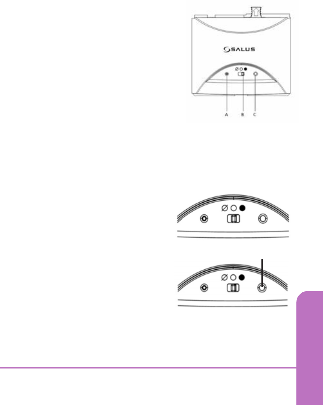
USER CONTROLS
Integral RF Boiler Control
A – LED
This LED will be on when the thermostat is demanding heat.
B – Mode Switch
ON –
Boiler will be on continuous
AUTO –
will follow instructions from the thermostat
OFF –
Boiler is off
C – SYNC Button -
This is used only for pairing the RF communications.
RXVBC605 INSTRUCTION MANUAL 17
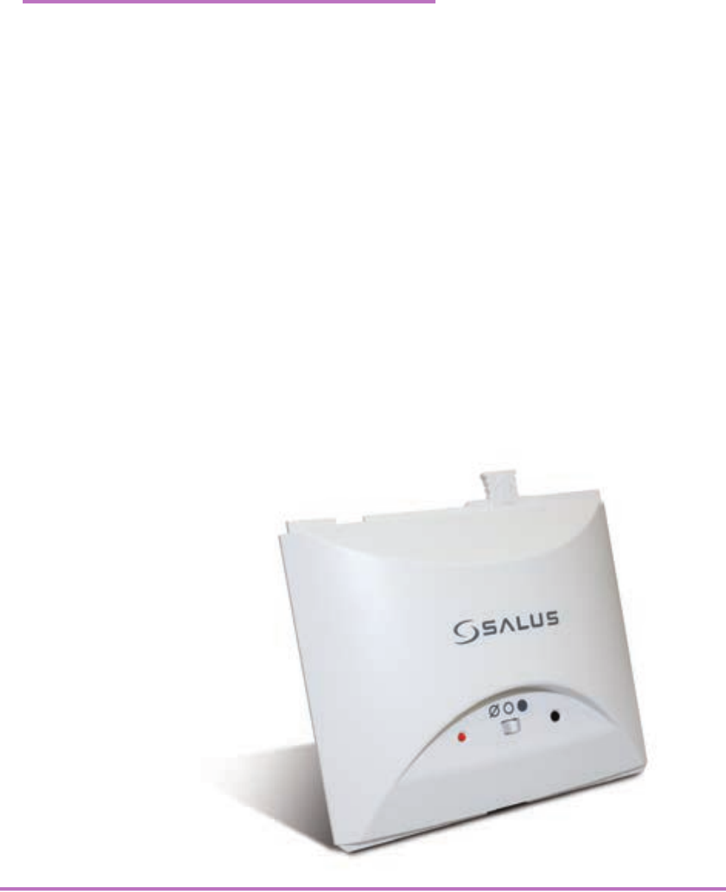
RXWBC605 RECEIVER
INTRODUCTION
The RXWBC605 comprises of an integral plug-in RF boiler control.
The RF boiler control is a direct replacement for the basic time
clock or blanking plate usually supplied with the boiler. Installing
the RF boiler control takes minutes. Once installed, you will
benefit from all the control features of the Salus thermostat.
INTEGRAL RF BOILER CONTROL
The Integral RF boiler control is the RF receiving unit for your
thermostat. This unit uses a plug-in connection to connect directly
to your boiler and provides the ON/OFF switching.
Features
• LED status indication
• Plug-in connection to boiler
• 3 position switch
• 868 MHz communication
RXWBC605 INSTRUCTION MANUAL
18
RF Transmission
The receiving range between your thermostat and the RF Boiler
Control is around 100 metres in open air, however many factors
can affect the RF transmission and shorten the operating
distance, e.g. shielding by thick walls, foil back plasterboard,
metal objects such as filing cabinets, general RF interference,
and so on. The operating range is generally around 30 metres,
which is large enough for most household applications.
Mounting the RF Integral Boiler Control to the boiler
DANGER!
• 24V & 230V: Do not Touch
Electrical Components or circuits.
• Isolate mains electricity supply
before starting any work and
observe all relevant safety
precautions.
• Follow electro static discharge
precaution. Do not touch any
visible PCB parts or components.
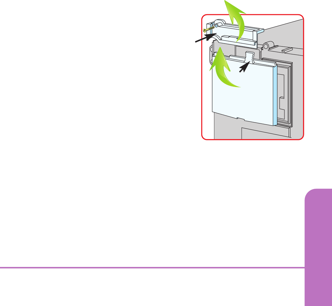
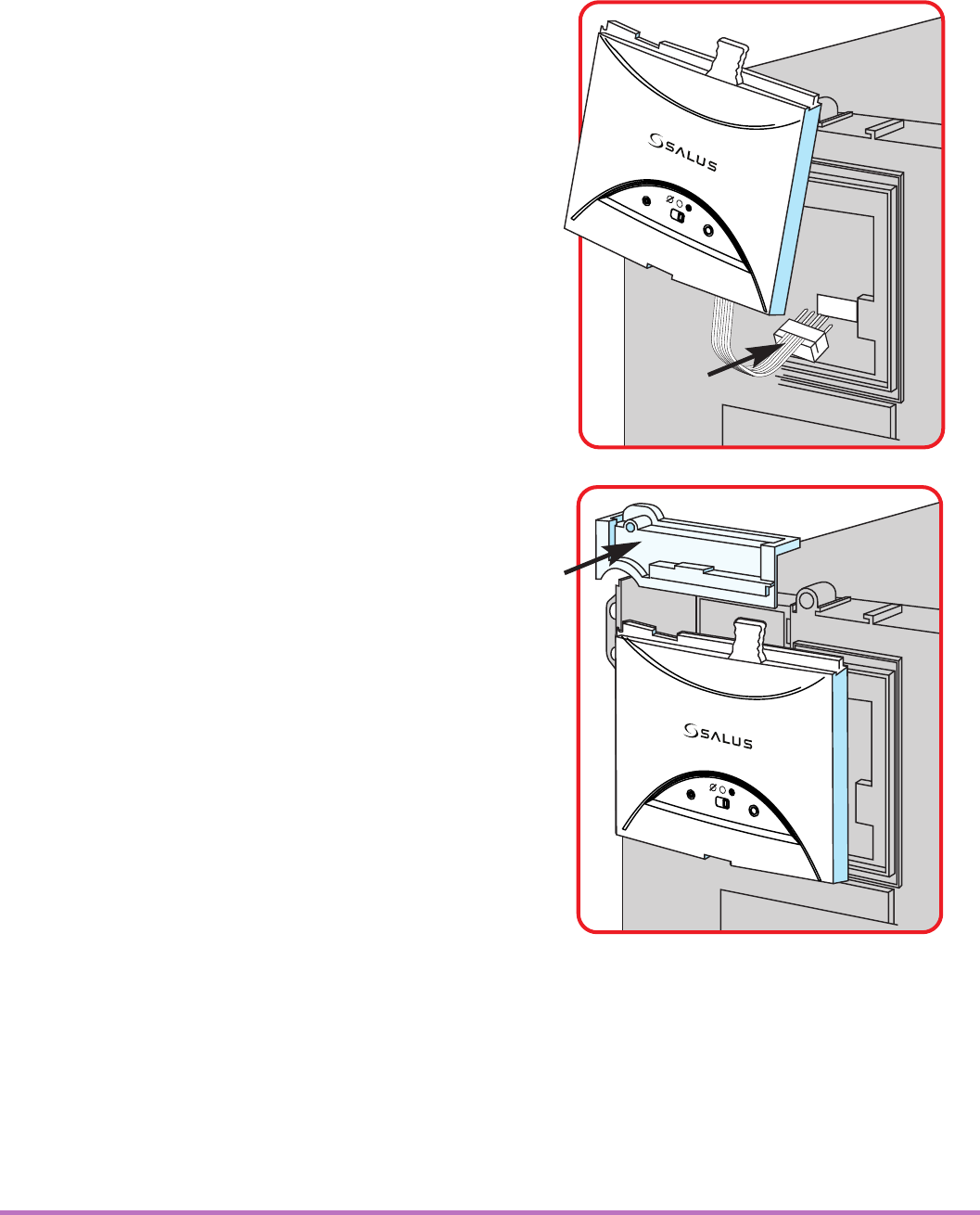
1. Switch off the boiler at its main supply. Remove the outer casing
and front fascia to allow access to the main control panel.
2. Remove cover panel A upwards to remove.
3. Pull top tab B upwards, then outwards to remove
blanking plate or existing control.
B
A
RXWBC605 INSTRUCTION MANUAL 19
4. First plug in the connector block
C ensuring correct orientation.
Remember to ensure the block
is fully connected.
5. Now locate the boiler control’s
four hooks then press in and
down. Replace Cover panel A.
6. Replace the front fascia
and boiler’s outer casing
C
A
RXWBC605 INSTRUCTION MANUAL
20
7. Before switching the boiler on at its mains supply,
ensure the module switch is in the OFF position .
8. To ensure the boiler control is connected properly, please
now move the switch to ON . The boiler should now Fire
and the LED on the your boiler control should illuminate
9. Now move the switch back to AUTO .
RXWBC605 INSTRUCTION MANUAL 21
RF Boiler Control
When the switch on the Boiler Module is in the AUTO position,
the boiler control will automatically receive the RF signal from
the thermostat and control the module output so that it switches
the boiler accordingly.
The user can also move the switch to the MANUAL ON position;
when in this mode, the boiler will be always turned on and the
LED indicator will also be lit constantly.
The user can also move the switch to the OFF position; when in
this mode, the boiler will not receive a signal from the RF
thermostat and the LED indicator will also be lit constantly.
RXWBC605 INSTRUCTION MANUAL
22
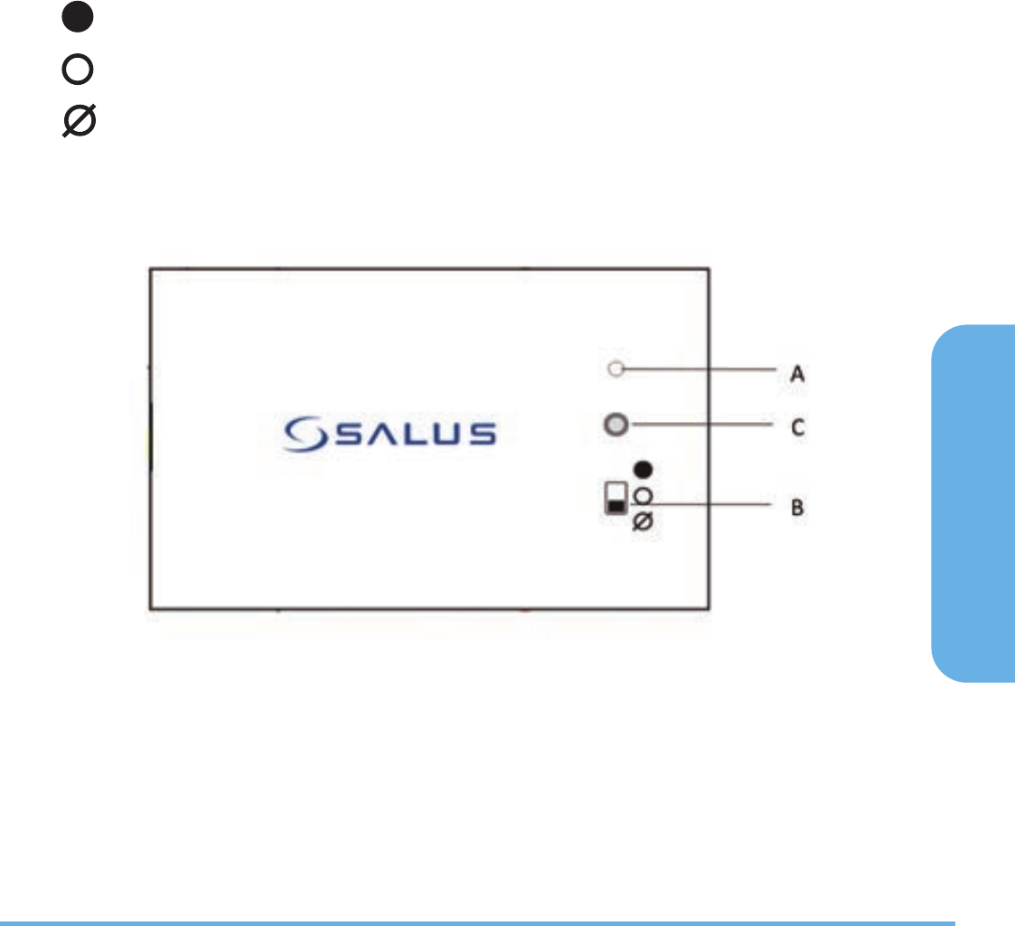
USER CONTROLS
Integral RF Boiler Control
A – LED This LED will be on when the
thermostat is demanding heat.
B – Mode Switch ON – Boiler will be on
continuous AUTO – will follow time and
temperature program in the transmitter
OFF – Boiler is off
C – SYNC Button - This is used only for
pairing the RF communications.
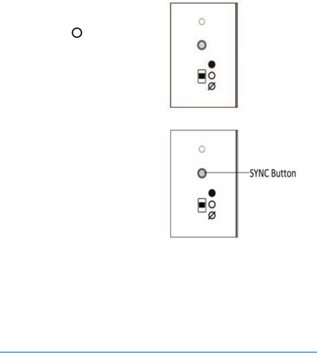
SETTING UP RF COMMUNICATION WITH
YOUR THERMOSTAT
If you find that your thermostat will not communicate with
integral boiler control please follow the steps below:
1. Ensure the switch on the
RF integral boiler module
is in the AUTO
2. Gently press and hold the SYNC
button with a blunt object. After
3 seconds the Boiler Control LED
will flash once every second to
indicate it is ready to pair and
ready to receive a signal from
the thermostat*.
* For full instructions on thermostat pairing see:
RT505TX Manual - Page 13 ST325TX Manual - Page 15
RT305TX Manual - Page 9 ST625TX Manual - Page 11
SYNC Button
RXWBC605 INSTRUCTION MANUAL 23

TECHNICAL SPECIFICATION RXRT505
Radio Frequency (RF) Settings
Operating Frequency: 868 MHz
Max. Operating Range: 100 metres (open air) or
30 metres (indoors)
Environment
Operating Temperature: 0 ºC to + 50 ºC
Storage Temperature: -20 ºC to + 60 ºC
RECEIVER INSTRUCTION MANUAL
24
TECHNICAL SPECIFICATION RXST625
Model: RXST625
Type: RF receiver, designed for
‘Volt Free’ applications.
Power Supply – Receiver
Power Source: 230V AC / 50Hz
Switching
Switching Voltage: 230V AC / 50Hz
Switching Current: 16A resistive, 5A inductive
Contact Type: Volt Free
Radio Frequency (RF) Settings
Operating Frequency: 868 MHz
Max. Operating Range: 100 metres (open air) 30 metres (indoors)
Protection rating: IP30

RECEIVER INSTRUCTION MANUAL 25
TECHNICAL SPECIFICATION RXWBC605
Radio Frequency (RF) Settings
Operating Frequency: 868 MHz
Max. Operating Range: 100 metres (open air) or
30 metres (indoors)
Environment
Operating Temperature: 0 ºC to + 50 ºC
Storage Temperature: - 20 ºC to + 60 ºC
TECHNICAL SPECIFICATION RXVBC605
Radio Frequency (RF) Settings
Operating Frequency: 868 MHz
Max. Operating Range: 100 metres (open air) or
30 metres (indoors)
Environment
Operating Temperature: 0 ºC to + 50 ºC
Storage Temperature: - 20 ºC to + 60 ºC

RECEIVER INSTRUCTION MANUAL
26
NOTES

Salus Controls warrants that this product will be free from any defect
in materials or workmanship, and shall perform in accordance with
its specification, for a period of two years from the date of purchase.
Salus Controls sole liability for breach of this warranty will be (at its
option) to repair or replace the defective product.
Warranty
Customer Name: ...........................................................................................
Customer Address: ........................................................................................
......................................................................................................................
Post Code: ........................................ Tel No: .................................................
Email: .............................................................................................................
Engineers Company: ......................................................................................
Tel No: ...........................................................................................................
Email: ............................................................................................................
Intallation Date: ............................................................................................
Engineers Name: ...........................................................................................
Engineers Signature: .....................................................................................
RECEIVER INSTRUCTION MANUAL 27

Email: sales@salus-tech.com Tel: 01226 323961
Email: tech@salus-tech.com Tel: 01226 323961
Sales
:
Technical
:
Salus Controls plc, Salus House, Dodworth Business Park South,
Whinby Road, Dodworth, Barnsley S75 3SP
salus-tech.
