Sam Ash Music AX300 Wireless Microphone System User Manual
Sam Ash Music Corporation Wireless Microphone System
User Manual

WIRELESS MICROPHONE SYSTEM
7!2.).'
4/02%6%.4&)2%/23(/#+(!:!2$$/./453%4()30,5'7)4(!.%84%./.#/2$2%#%04!#,%
/2/4(%2/54,%45.,%334(%",!$%3#!."%&5,,9).3%24%$4/02%3%.4",!$%%80/352%
4/02%6%.4&)2%/23(/#+(!:!2$$/./4%80/3%4()3!00,)!.#%4/2!)./2-/)3452%
4/026%.4%,%#42)#!,3(/#+-!4#(7)$%",!$%0,5'4/7)$%3,/4&5,,9).3%24
2)3+/&%,%#42)#3(/#+
$/./4/0%.
#!54)/.
4HISLIGHTNIGFLASHWITHARROW
HEADSYMBOLWITHINANEQUI
LATERALTRIANGLEISINTENDEDTO
ALERTTHEUSERTOTHEPRESENCE
OF UNINSULATED hDANGEROUS
VOLTAGEv WITHIN THE PRODUCTS
ENCLOSURE THAT MAY BE OF
SUFFICIENT MAGNITUDE TO
CONSTITUTE A RISK OF ELECTRIC
SHOCKTOPERSONS
7ARNING4OREDUCETHERISKOF
ELECTRIC SHOCK DO NOT REMOVE
COVER OR BACK NO USER
SERVICEABLEPARTSINSIDE2EFER
SERVING TO QUALIFIED SERVICE
PERSONNEL
4HEEXCLAMATIONPOINTWITHIN
AN EQUILATERAL TRIANGLE IS
INTENDEDTOALERTTHEUSERTO
THE PRESENCE OF IMPORTANT
OPERATING AND MAINTENANCE
SERVICING INSTRUCTIONS IN
THE LITERATURE ACCOMPANYING
THEAPPLIANCE
2EADTHESEINSTRUCTIONS
+EEPTHESEINSTRUCTIONS
(EEDALLWARNINGS
&OLLOWALLINSTRUCTIONS
$ONOTUSETHISAPPARATUSNEARWATER
#LEANONLYWITHDRYCLOTH
$ONOTBLOCKANYVENTIATIONOPENINGS)NSTALLINACCORDANCEWITHTHEMANUFACTURESINSTRUCTIONS
$O NOT INSTALL NEAR ANY HEAT SOURCES SUCH AS RADIATORS HEAT REGISTERS STOVES OR OTHER APPARTUS
INCLUDINGAMPLIFIERSTHARPRODUCEHEAT
$ONOT DEFEATTHE SAFETYPURPOSEOF THEPOLARIZED ORGROUNDING TYPEPLUG !POLARIZEDPLUG HASTWO
BLADESWITHONEWIDERTHANTHEOTHER!GROUNDINGTYPEPLUGHASTWOBLADESANDATHIRDGROUNDINGPRONG
4HEWIDEBLADEORTHETHIRDPRONGAREPROVIDEDFORYOURSAFETY)FTHEPROVIDEDPLUGDOESNOTFITINTOYOUR
OUTLETCONSULTANELECTRICIANFORREPLACEMENTOFTHEOBSOLETEOUTLET
0ROTESTTHEPOWERCORDFROMBEINGWALKEDONORPINCHEDPARTICULARYATTHEPLUGSCONVENIENCERECEP
TACLESANDATTHEPOINTWHERETHEYEXITFROMTHEAPPARATUS
/NLYUSEATTACHMENTSACCESSORIESSPECIFIEDBYTHEMANUFACTURER
5SEONLYWITHTHECARTSTANDTRIPODBRACKETORTABLESPECIFIEDBYTHEMANUFAC
TURER OR SOLD WITH THE APPARATUS 7HEN A CART IS USED USE CAUTION WHEN
MOVINGTHECARTAPPARATUSCOMBINATIONTOAVOIDINJURYFROMTIPOVER
5NPLUGTHEAPPARATUSDURINGLIGHTENINGSORTORWHENUNUSEDFORLONGPERIODSOFTIME
2EFERALLSERVICINGTOQUALIFIEDPERSONNEL3ERVINGISREQUIREDWHENTHEAPPARATUSHASBEENDAMAGEDIN
ANYWAYSUCHASPOWERSUPPLYCORDORPLUGISDAMAGEDLIQUIDHASBEENSPILLEDOROBJECTSHAVEFALLEN
INTO THE APPARATUS HAS BEEN EXPOSED TO RAIN OR MOISTURE DOES NOT OPERATE NORMALLY OR HAS BEEN
DROPPED
4HISAPPLIANCESHALLNOTBEEXPOSEDTODRIPPINGORSPLASHINGWATERANDTHATNOOBJECTFILLEDWITHLIQUID
SUCHASVASESSHALLBEPLACEDONTHEAPPARATUS
#AUTIONTOPREVENTELECRICALSHOCKMATCHWIDEBLADEPLUGWIDESLOTFULLYINSERT
0LEASEKEEPAGOODVENTILATIONENVIRONMENTAROUNDTHEENTIREUNIT
)-0/24!.43!&%49).3425#4)/.3

ATTENTION: Pour éviter tout risque d’électrocution ou d’incendie, ne pas exposer cet appareil à la pluie ou à
l’humidité. Pour éviter tout risque d’électrocution, ne pas ôter le couvercle ou le dos du boîtier. Cet appareil ne con-
tient aucune pièce remplaçable par l'utilisateur. Conez toutes les réparations à un personnel qualié. Le signe
avec un éclair dans un triangle prévient l’utilisateur de la présence d’une tension dangereuse et non isolée dans
l’appareil. Cette tension constitue un risque d’électrocution. Le signe avec un point d’exclamation dans un tri-
angle prévient l’utilisateur d’instructions importantes relatives à l’utilisation et à la maintenance du produit.
Consignes de sécurité importantes
1. Veuillez lire toutes les instructions avant d’utiliser l’appareil.
2. Conserver ces instructions pour toute lecture ultérieure.
3. Lisez avec attention toutes les consignes de sécurité.
4. Suivez les instructions du fabricant.
5. Ne pas utiliser cet appareil près d’une source liquide ou dans un lieu humide.
6. Nettoyez l’appareil uniquement avec un tissu humide.
7. Veillez à ne pas obstruer les fentes prévues pour la ventilation de l’appareil. Installez l’appareil selon les
instructions du fabricant.
8. Ne pas installer près d’une source de chaleur (radiateurs, etc.) ou de tout équipement susceptible de génér-
er de la chaleur (amplicateurs de puissance par exemple).
9. Ne pas retirer la terre du cordon secteur ou de la prise murale. Les ches canadiennes avec polarisation
(avec une lame plus large) ne doivent pas être modiées. Si votre prise murale ne correspond pas au
modèle fourni, consultez votre électricien.
10. Protégez le cordon secteur contre tous les dommages possibles (pincement, tension, torsion,, etc.). Veillez à
ce que le cordon secteur soit libre, en particulier à sa sortie du boîtier.
11. Déconnectez l’appareil du secteur en présence d’orage ou lors de périodes d’inutilisation prolongées.
12. Consultez un service de réparation qualié pour tout dysfonctionnement (dommage sur le cordon secteur,
baisse de performances, exposition à la pluie, projection liquide dans l’appareil, introduction d’un objet
dans le boîtier, etc.).
ACHTUNG: Um die Gefahr eines Brandes oder Stromschlags zu verringern, sollten Sie dieses Gerät weder
Regen noch Feuchtigkeit aussetzen.Um die Gefahr eines Stromschlags zu verringern, sollten Sie weder Deckel
noch Rückwand des Geräts entfernen. Im Innern benden sich keine Teile, die vom Anwender gewartet
werden können. Überlassen Sie die Wartung qualiziertem Fachpersonal.Der Blitz mit Pfeilspitze im gleich-
seitigen Dreieck soll den Anwender vor nichtisolierter “gefährlicher Spannung” im Geräteinnern warnen. Diese
Spannung kann so hoch sein, dass die Gefahr eines Stromschlags besteht. Das Ausrufezeichen im gleichseiti-
gen Dreieck soll den Anwender auf wichtige Bedienungs- und Wartungsanleitungen aufmerksam machen, die
im mitgelieferten Informationsmaterial näher beschrieben werden.
Wichtige Sicherheitsvorkehrungen
1. Lesen Sie alle Anleitungen, bevor Sie das Gerät in Betrieb nehmen.
2. Bewahren Sie diese Anleitungen für den späteren Gebrauch gut auf.
3. Bitte treen Sie alle beschriebenen Sicherheitsvorkehrungen.
4. Befolgen Sie die Anleitungen des Herstellers.
5. Benutzen Sie das Gerät nicht in der Nähe von Wasser oder Feuchtigkeit.
6. Verwenden Sie zur Reinigung des Geräts nur ein feuchtes Tuch.
7. Blockieren Sie keine Belüftungsönungen. Nehmen Sie den Einbau des Geräts nur entsprechend den
Anweisungen des Herstellers vor.
8. Bauen Sie das Gerät nicht in der Nähe von Wärmequellen wie Heizkörpern, Wärmeklappen, Öfen oder
anderen Geräten (inklusive Verstärkern) ein, die Hitze erzeugen.
9. Setzen Sie die Sicherheitsfunktion des polarisierten oder geerdeten Steckers nicht außer Kraft. Ein pola-
risierter Stecker hat zwei ache, unterschiedlich breite Pole. Ein geerdeter Stecker hat zwei ache Pole und
einen dritten Erdungsstift. Der breitere Pol oder der dritte Stift dient Ihrer Sicherheit. Wenn der vorhandene
Stecker nicht in Ihre Steckdose passt, lassen Sie die veraltete Steckdose von einem Elektriker ersetzen.
10. Schützen Sie das Netzkabel dahingehend, dass niemand darüber laufen und es nicht geknickt werden
kann. Achten Sie hierbei besonders auf Netzstecker, Mehrfachsteckdosen und den Kabelanschluss am
Gerät.
11. Ziehen Sie den Netzstecker des Geräts bei Gewittern oder längeren Betriebspausen aus der Steckdose.
12. Überlassen Sie die Wartung qualiziertem Fachpersonal. Eine Wartung ist notwendig, wenn das Gerät auf
irgendeine Weise, beispielsweise am Kabel oder Netzstecker beschädigt wurde, oder wenn Flüssigkeiten
oder Objekte in das Gerät gelangt sind, es Regen oder Feuchtigkeit ausgesetzt war, nicht mehr wie
gewohnt betrieben werden kann oder fallen gelassen wurde.

PRECAUCION: Para reducir el riesgo de incendios o descargas, no permita que este aparato quede expuesto a la lluvia
o la humedad. Para reducir el riesgo de descarga eléctrica, nunca quite la tapa ni el chasis. Dentro del aparato no hay
piezas susceptibles de ser reparadas por el usuario. Dirija cualquier reparación al servicio técnico ocial. El símbolo
del relámpago dentro del triángulo equilátero pretende advertir al usuario de la presencia de“voltajes peligrosos” no
aislados dentro de la carcasa del producto, que pueden ser de la magnitud suciente como para constituir un riesgo de
descarga eléctrica a las personas. El símbolo de exclamación dentro del triángulo equilátero quiere advertirle de la exis-
tencia de importantes instrucciones de manejo y mantenimiento (reparaciones) en los documentos que se adjuntan
con este aparato.
Instrucciones importantes de seguridad
1. Lea todo este manual de instrucciones antes de comenzar a usar la unidad.
2. Conserve estas instrucciones para cualquier consulta en el futuro.
3. Cumpla con todo lo indicado en las precauciones de seguridad.
4. Observe y siga todas las instrucciones del fabricante.
5. Nunca utilice este aparato cerca del agua o en lugares húmedos.
6. Limpie este aparato solo con un trapo suave y ligeramente humedecido.
7. No bloquee ninguna de las aberturas de ventilación. Instale este aparato de acuerdo a las instrucciones del fabri-
cante.
8. No instale este aparato cerca de fuentes de calor como radiadores, calentadores, hornos u otros aparatos (incluy-
endo amplicadores) que produzcan calor.
9. No anule el sistema de seguridad del enchufe de tipo polarizado o con toma de tierra. Un enchufe polarizado
tiene dos bornes, uno más ancho que el otro. Uno con toma de tierra tiene dos bornes normales y un tercero para
la conexión a tierra. El borne ancho o el tercero se incluyen como medida de seguridad. Cuando el enchufe no
encaje en su salida de corriente, llame a un electricista para que le cambie su salida anticuada.
10. Evite que el cable de corriente quede en una posición en la que pueda ser pisado o aplastado, especialmente en
los enchufes, receptáculos y en el punto en el que salen de la unidad.
11. Desconecte de la corriente este aparato durante las tormentas eléctricas o cuando no lo vaya a usar durante un
periodo de tiempo largo.
12. Dirija cualquier posible reparación solo al servicio técnico ocial. Deberá hacer que su aparato sea reparado
cuando esté dañado de alguna forma, como si el cable de corriente o el enchufe están dañados, o si se han der-
ramado líquidos o se ha introducido algún objeto dentro de la unidad, si esta ha quedado expuesta a la lluvia o la
humedad, si no funciona normalmente o si ha caído al suelo.
ATTENZIONE: per ridurre il rischio di incendio o di scariche elettriche, non esponete questo apparecchio a pioggia o
umidità. Per ridurre il pericolo di scariche elettriche evitate di rimuoverne il coperchio o il pannello posteriore. Non esis-
tono all'interno dell'apparecchio parti la cui regolazione è a cura dell'utente. Per eventuale assistenza, fate riferimento
esclusivamente a personale qualicato. Il fulmine con la punta a freccia all'interno di un triangolo equilatero avvisa l'utente
della presenza di "tensioni pericolose" non isolate all'interno dell'apparecchio, tali da costituire un possibile rischio di
scariche elettriche dannose per le persone. Il punto esclamativo all'interno di un triangolo equilatero avvisa l'utente della
presenza di importanti istruzioni di manutenzione (assistenza) nella documentazione che accompagna il prodotto.
Importanti Istruzioni di Sicurezza
1. Prima di usare l'apparecchio, vi preghiamo di leggerne per intero le istruzioni.
2. Conservate tali istruzioni per una eventuale consultazione futura.
3. Vi preghiamo di rispettare tutte le istruzioni di sicurezza.
4. Seguite tutte le istruzioni del costruttore.
5. Non usate questo apparecchio vicino ad acqua o umidità.
6. Pulite l'apparecchio esclusivamente con un panno asciutto.
7. Evitate di ostruire una qualsiasi delle aperture di ventilazione. Posizionatelo seguendo le istruzioni del costruttore.
8. Non posizionatelo vicino a sorgenti di calore come radiatori, scambiatori di calore, forni o altri apparecchi (amplica-
tori compresi) in grado di generare calore.
9. Non disattivate la protezione di sicurezza costituita dalla spina polarizzata o dotata di collegamento a terra. Una
spina polarizzata è dotata di due spinotti, uno più piccolo ed uno più grande. Una spina dotata di collegamento a
terra è dotata di due spinotti più un terzo spinotto di collegamento a terra. Questo terzo spinotto, eventualmente
anche più grande, viene fornito per la vostra sicurezza. Se la spina fornita in dotazione non si adatta alla vostra
presa, consultate un elettricista per la sostituzione della presa obsoleta.
10. Proteggete il cavo di alimentazione in modo che non sia possibile camminarci sopra né piegarlo, con particolare
attenzione alle prese, ai punti di collegamento e al punto in cui esce dall'apparecchio.
11. Staccate l'apparecchio dalla alimentazione in caso di temporali o tempeste o se non lo usate per un lungo periodo.
12. Per l'assistenza, fate riferimento esclusivamente a personale qualicato. È necessaria l'assistenza se l'apparecchio ha
subito un qualsiasi tipo di danno, come danni al cavo o alla spina di alimentazione, nel caso in cui sia stato versato
del liquido o siano caduti oggetti al suo interno, sia stato esposto a pioggia o umidità, non funzioni correttamente
o sia stato fatto cadere.

Copyright 2008-2009, Samson Technologies Corp.
Printed January, 2009 v1.1
Samson Technologies Corp.
45 Gilpin Avenue
Hauppauge, New York 11788-8816
Phone: 1-800-3-SAMSON (1-800-372-6766)
Fax: 631-784-2201
www.samsontech.com
Table of Contents
Contents
Introduction. . . . . . . . . . . . . . . . . . . . . . . . . . . . . 7
QuickStart . . . . . . . . . . . . . . . . . . . . . . . . . . . . . . 8
Guided Tour - AR300 Receiver / Front Panel . . . . . . 10-11
Guided Tour - AR300 Receiver / Rear Panel . . . . . . . . 12
Guided Tour - AX300 Transmitter. . . . . . . . . . . . . 13-14
Setting Up and Using Your AirLine Synth system . . 15-17
AR300 Operation. . . . . . . . . . . . . . . . . . . . . . . 18-19
Specifications. . . . . . . . . . . . . . . . . . . . . . . . . 20-21

7
Introduction
Welcome to Samson AirLine Synth—the next generation of wireless systems! Wireless
microphone and instrument systems were originally developed to eliminate cables,
providing unparalleled freedom of movement. AirLine Synth takes this concept
to a new level with transmitters so small, lightweight and aerodynamic, they are
nearly invisible, providing a completely “hassle-free” user experience. To create the
world’s smallest frequency agile wireless transmitters, we developed new proprietary
technology. Featuring miniaturized circuitry and the ability to operate on a single AA
battery (with 10 hours typical battery life), these transmitters also provide signicantly
improved wireless reception and sound quality. What’s more, the AR300 receiver
developed especially for the AirLine Synth microphone system provides over 300
channels with automatic Channel Scan to help you nd the clearest frequency to
operate on. The convenient, all metal half-rack chassis design features a large backlit
LCD display and includes a rackmount kit to install in a standard 19-inch equipment
rack. The Samson AirLine Synth UHF microphone system is designed to replace the
cable between your microphone your PA mixer, freeing you to roam the stage or
even visit the audience in the middle of your performance! It operates in the UHF
frequency range and contains an AR300 “half-rack” receiver and the AX300 plug-in
micro-transmitter with standard XLR connector designed to t the included Samson
Q7 or any other dynamic microphones.
In this manual, you’ll nd a detailed description of the features of your AirLine Synth
system, as well as a guided tour through all components, step-by-step instructions for
setting up and using your system and full specications. If your AirLine Synth system
was purchased in the United States, you’ll also nd a warranty card enclosed—don’t
forget to ll it out and mail it! This will enable you to receive online technical support
and will allow us to send you updated information about this and other Samson
products in the future. If your AirLine Synth system was purchased outside of the
U. S., contact your local distributor for warranty details. Also, be sure to check out
our website (http://www.samsontech.com) for complete information about our full
product line.
SPECIAL NOTE for U.S. purchasers: Should your AirLine Synth system ever require
servicing, a Return Authorization number (RA) is necessary. Without this number,
the unit will not be accepted. If your AirLine Synth system was purchased in the
United States, please call Samson at 1-800-372-6766 for a Return Authorization
number prior to shipping your system. If possible, return the unit in its original carton
and packing materials. If your AirLine Synth system was purchased outside of the U. S.,
contact your local distributor for information.
If you’ve had some prior experience using wireless systems, these QuickStart
instructions will get you up and running with your AirLine UHF microphone system in
a matter of minutes! Detailed instructions for setting up and using your AirLine Synth
system can be found on page 15 of this manual, and the “Guided Tour” sections on
pages 10- 14 provide full descriptions of all AirLine component controls and displays.
1. Unpack the AR300 receiver and AX300
transmitter and plug the AX300 into
the include Samson Q7 or any dynamic
microphone.
2. Physically place the AR300 receiver near
your mixer. Extend its antennas vertically
and spread the tips horizontally outwards.
3. Set the power switch on your AX300
transmitter to the “off” position (away from
the arrow) and place a fresh AA battery
in it. Then turn the transmitter back on
momentarily; its LED will flash once and
then go off if the battery is sufficiently
strong. Once battery strength is verified,
turn the transmitter off again, then put it
aside for now.
4. Connect the included AC power supply to the rear of the AR300 and then to an
available wall socket. Turn the AR300 on momentarily to confirm that the unit has
power. Then turn the AR300 power off.
5. Turn your mixer off, or mute the channel and make the physical cable connection
between an audio input and the AR300 output jack.
6. Turn the Level knob on the AR300 completely counterclockwise, then turn its
power on.
QuickStart
8
QuickStart
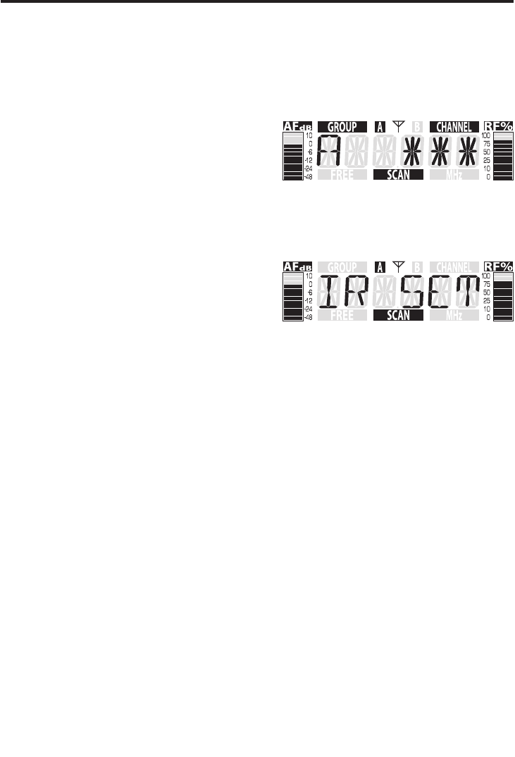
7. Now to set the channel, press and hold
the EDIT control until the display shows
the group number with three asterisks.
Next, the AR300 will automatically find the
clearest channel and you will see it in the
Channel number of the display just before
the IR SET will begin.
8. Once you see the IR SET flashing in the
LCD display, hold the transmitter, with the
bottom of the AX300 facing towards the
AR300, approximately 6 inches away from
the receiver and turn the AX300 power
switch on. The AR300 will transmit the
channel number to AX300 over infrared
light and you will see the corresponding
absolute channel number in the transmitter LCD.
8. Turn on the mixer, or unmute the channel, but keep its volume all the way down.
Begin speaking or singing at a normal performance level while observing the AF
Meter. If the AF Meter reads above “0” (indicating a Peak condition) even with the
AR300 Level control fully counterclockwise, slowly adjust the GAIN on the inside
of the AX300 to the point where the AF Meter occasionally reads “0” during the
very loudest passages, then back it off just slightly. Finally, raise the level of your
connected mixer until the desired volume is reached
9. Do a walkaround through the intended area of coverage while observing the
receiver’s RF Meter; it should continue to read about “75%”, indicating sufficient RF
reception in all areas of coverage. If not, reposition the AR300 or its antennas as
necessary.
10. If you hear any spurious noise from the receiver output when the transmitter
is turned off, use the supplied plastic screwdriver to adjust the AR300 Squelch
control, slowly turning it clockwise to the point at which the noise disappears.
9
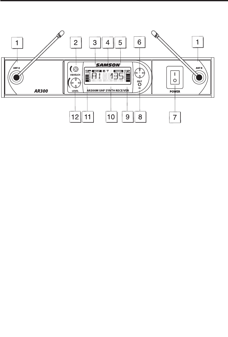
1. Antennas (A and B) - The antenna mountings allow full rotation for optimum
placement. In normal operation, both Antenna A (the antenna on the left) and
Antenna B (the antenna on the right) should be placed in a vertical position. Both
antennas can be folded inward for convenience when transporting the AR300. See
the “Setting Up and Using Your AirLine Synth System” section on page 15 in this manual
for information about antenna installation and positioning.
2: Squelch – This control determines the maximum range of the AR300 before audio
signal dropout. Although it can be adjusted using the supplied plastic screwdriver,
it should normally be left at its factory setting. See the “Setting Up and Using Your
AirLine Synth System” section on page 15 in this manual for more information.
3: Group Channel - This displays shows the current Group and Group Channel
number. A letter indicates Groups and the Group Channel number is indicated by 0
through 9.
4: Antenna indicators – In order to maximize reception and distance, the AR300
implements true diversity receiver technology with dual RF strips. The A and B
antenna icon shows which of the receiver’s two RF strips is active.
5: Absolute Channel – This display shows the exact channel number from the 319
channel plan.
Guided Tour - AR300 Receiver / Front Panel
10

6: EDIT Control – This rotary encoder control knob is used to control and set several
menu functions and parameters displayed in the LCD display and it is also used to
preform the automatic Channel Scan.
7: Power Switch - Use this to turn the AR300 power on and off. When the receiver is
on, the LCD backlight is lit.
8: IR Transmitter – During “IR SET” an Infrared light is used to set the transmitter
channel.
9: RF Meter – 12-segment bar meter used to display the level of the radio frequency
reception.
10: LCD Display – The 47mm x 17mm backlit display show information for Frequency,
Channel, Group, Absolute Channel, Antenna, AF, RF, Scan, and IR Set.
11: AF Meter - 12-segment bar meter used to display the amount of the audio input
level.
12: Level control - This knob sets the level of the audio signal being output through
both balanced output connectors on the rear panel (see C and D on page 12 in
this manual). Reference level is obtained when the knob is turned fully clockwise
(to its “10” setting).
Guided Tour - AR300 Receiver / Front Panel
11
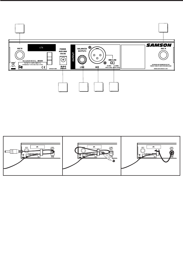
A: Antenna socket - D hole knockout for mounting the antennas to the rear panel
using the optional rear antenna kit.
B: DC input - Connect the supplied power adapter here, using the strain relief as
shown in the illustration below. WARNING: Do not substitute any other kind of
power adapter; doing so can cause severe damage to the AR300 and will void your
warranty.
C: 1/4-inch output* - Use this 1/4" jack when connecting the AR300 to your guitar
amp or to line level equipment. The output connection can be either balanced or
unbalanced. Wiring is as follows: tip hot, ring cold, sleeve ground.
D: XLR output* - Use this electronically balanced low impedance (600 Ohm) XLR jack
when connecting the AR300 to professional (+4) audio equipment. Pin wiring is as
follows: Pin 1 ground, Pin 2 high (hot), and Pin 3 low (cold).
E: Audio Output Level switch - Sets the audio output level attenuation of the XLR
output to -20 dBm (line level) or -40 dBm (mic level). See “Setting Up and Using Your
AirLine Synth System” on page 15.
* If required, both outputs can be used simultaneously.
A
BD
A
E
C
Guided Tour - AR300 Receiver / Rear Panel
-
12
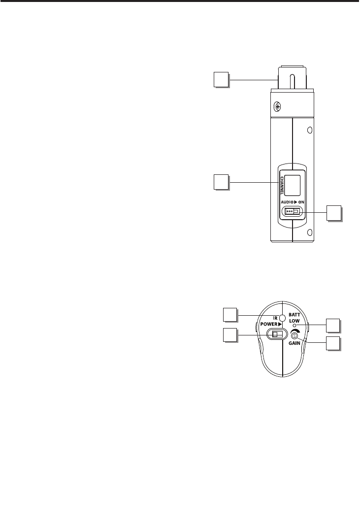
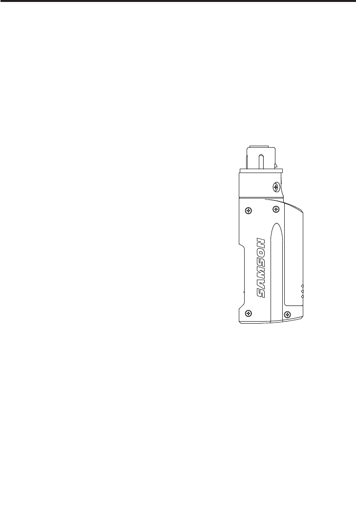
1: Plug - Insert this standard 3-pin XLR plug into
your the included Samson Q7 or any dynamic
microphone.
2: LCD Display – This three digit Liquid Crystal
Display indicates the Absolute Channel
number that the transmitter is set to.
3: Audio On switch – This switch is used to
temporarily turn off the audio output of the
transmitter. Move this switch away from “ON”
to turn off the output and move the switch in
the direction of “ON” to turn the output on.
4: IR Lens - This acrylic window is used to
capture the infrared signal sent from the
AR300 during the IR SET to channelize the
AX300.
5: Power switch - Move this switch in the
direction of the arrow to turn the AR300
power; move it away from the arrow to turn
power off.
6: Power / Battery LED - This red LED flashes
once when the AX300 is first turned
indicating the transmitter has power. It will
remain off as long as they battery is a good
operating level. The LED lights steadily red
when there are less than 2 hours of battery
power remaining, indicating that the battery
needs to be changed. In order to avoid
compromising audio fidelity (or having the
AX300 stop working completely), you should
always replace the battery with a fresh one immediately whenever this LED lights
red.
7: Gain - Move this control in the direction of the arrow (counterclockwise) to reduce
the output of the AX300 when the speaker’s or singer’s voice is putting out too hot
of a signal. See the “Setting Up and Using Your Synth AirLine Synth System” section on
page 15 in this manual.
1
2
3
Guided Tour - AX300 Transmitter
4
5
7
6
13
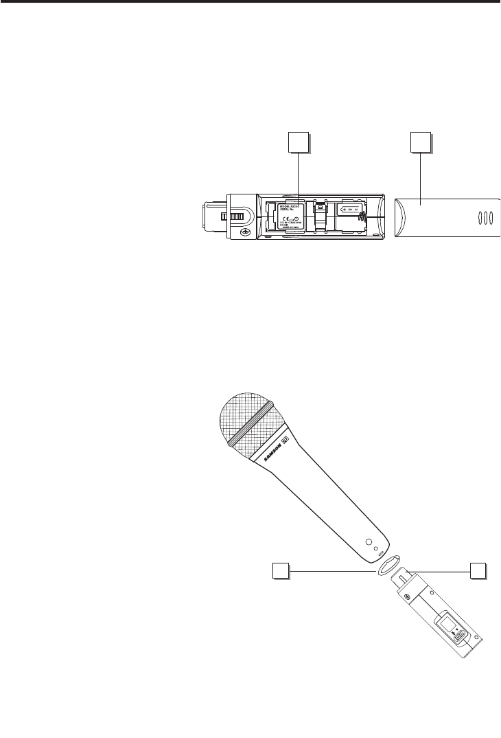
8: Battery compartment -
Insert a standard AA alkaline
battery here, being sure to
observe the plus and minus
polarity markings shown.
We recommend the Duracell
type battery. Although
rechargeable Ni-Cad batteries
can be used, they do not
supply adequate current
for more than four hours.
WARNING: Do not insert the
battery backwards; doing so
can cause severe damage to
the AX300 and will void your
warranty.
9: Battery cover - Pull back gently
on this cover at the ribbing and
pry upwards to remove. See the
“Setting Up and Using Your Synth
AirLine Synth System” section on
page 12 in this manual.
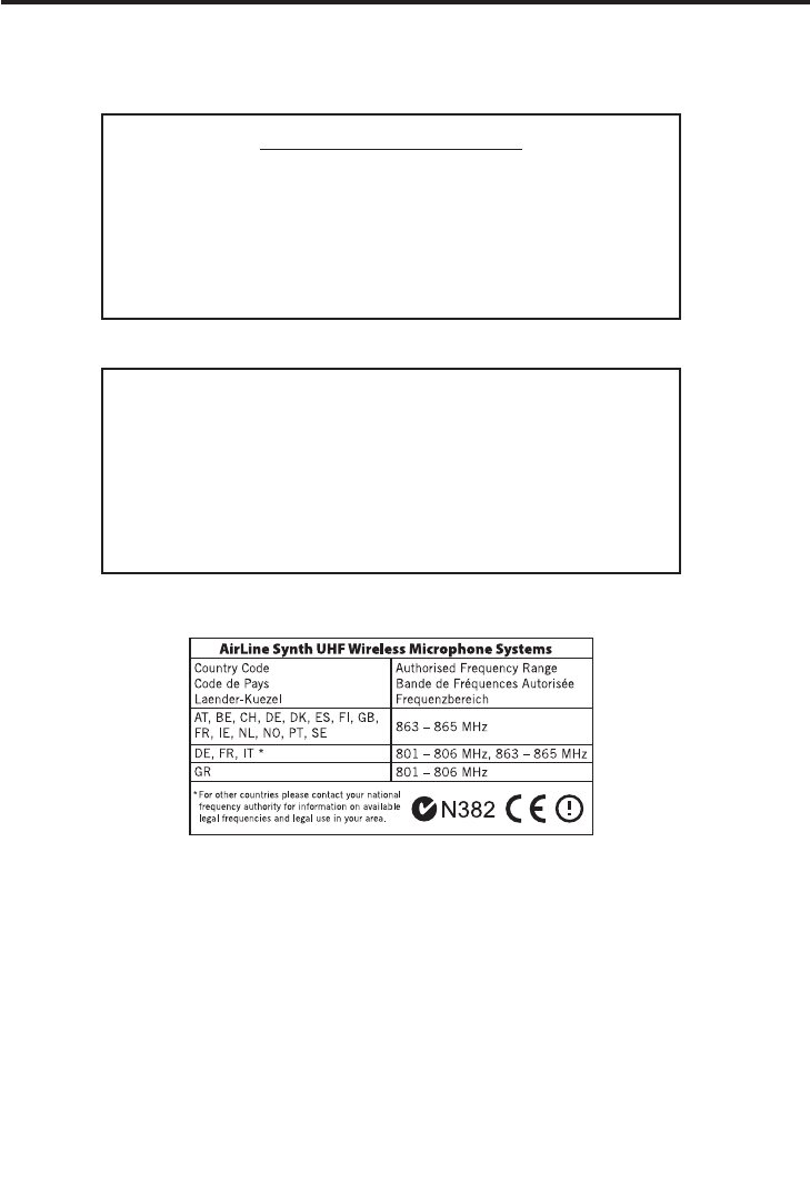
10: XLR connector - Connect this
standard female XLR connector
into any standard wired
dynamic microphone in order
to make it a wireless mic.
11: Rubber gasket - If necessary,
use this provided rubber
gasket in order to make a
solid connection between the
AX300 XLR connector and your
microphone (note that not all
microphones require its use).
8 9
Guided Tour - AX300 Transmitter
1110
14

The basic procedure for setting up and using your AirLine Synth system takes only a
few minutes:
1. Remove all packing materials (save them in case of need for future service) and
check to make sure that the supplied power adapter is the correct voltage for your
country. If not, contact your distributor or, if purchased in the United States, Samson
Technical Support at 1-800-372-6766.
2. Physically place the AR300 receiver next to your mixer. The general rule of thumb is
to maintain “line of sight” between the receiver and transmitter so that the person
using the transmitter can see the receiver.
3. Extend the AR300 antennas and spread the tips horizontally outwards at least 5
inches.
4. Make sure the Power On-Off switch in your AX300 transmitter is set to “Off” and
that the MUTE is also set to “ON”. Pull back gently on the AX300 battery cover at the
ribbing and pry it upwards to remove it. Please use care when opening this cover
as undue force can damage it. Install a fresh AA alkaline battery in the battery
compartment, being sure to observe the polarity markings. Then carefully replace
the battery cover and gently press down on it until it clicks. Momentarily turn on
the power to the transmitter by sliding its Power On-Off switch in the direction of
the arrow; the “Power/Battery” LED will flash if the battery is sufficiently strong (if it
lights steadily, the battery has less than 2 hours of power remaining and should be
replaced). Once battery strength is verified, turn the transmitter off again and place
it aside for now.
5. With the Power switch on the AR300 set to the “Off” position, connect the included
power adapter. Turn the AR300 on momentarily to confirm that the unit is receiving
power. You’ll see the LCD display light up. Then turn the AR300 power off.
Setting Up and Using Your AirLine Synth System
15

6. Make the physical cable connection between the AR300 output jack and an audio
input of your mixer. Leave your mixer and power amplifier off at this time.
7. Turn the Level knob on the AR300 completely counterclockwise, then set its Power
switch up to turn it on. The LCD display light will illuminate.
8. Now to set the channel, press and hold the EDIT control until the display reads CH
SCAN. Next, the AR300 will automatically find the clearest channel and you will see
it in the Channel number of the display just before the IR SET will begin.
9. Once you see the IR SET flashing in the LCD display, hold the transmitter, with the
bottom facing towards the AR300, approximately 6 inches away from the receiver
and turn the AX300 power switch on. The AR300 will transmit the channel number
to AX300 over infrared light and you will see the corresponding absolute channel
number in the transmitter LCD.
10. The RF Meter on the AR300 receiver should now be active, indicating that it is
receiving valid RF signal and is placed and positioned correctly.
11. Now it’s time to set the audio levels. Turn on your mixer and/or amplifier but
keep its volume all the way down. Plug the AX300 into the included Samson Q7
or any dynamic microphone. Begin speaking or singing at a normal performance
level while observing the AR300 AF Meter. If all the bars are lit, indicating a Peak
condition, even with the AR300 Level control fully counterclockwise, turn the
Gain control down. If the AF Meter bars are showing a weak level, slowly turn the
AX300’s Gain control clockwise to the point where the AF Meter reaches ‘‘0” during
the very loudest passages, then back it off just slightly; this will ensure maximum
signal to noise ratio. Now, raise the Level on the AR300. Finally, raise the level of
your mixer and/or amplifier until the desired volume is reached.
Setting Up and Using Your AirLine Synth System
16

12. Temporarily turn down the level of your mixer or amplifier and turn off the power
to your transmitter, leaving the AR300 receiver on. Then restore the previously
set level of your mixer or amplifier. With the transmitter off, the receiver output
should be totally silent; if it is, skip ahead to the next step. If it isn’t (that is,
if you hear some noise), you may need to adjust the AR300 Squelch control.
When the Squelch control is at its minimum setting, the AirLine Synth system
always provides maximum range without dropout; however, depending upon
the particular environment your system is used in, you may need to reduce that
range somewhat in order to eliminate band noise when the AX300 transmitter is
turned off. To do so, use the provided screwdriver to rotate the Squelch control
completely counterclockwise (to the “Min” position), then slowly turn it clockwise
until the noise disappears. If no noise is present at any position, leave it at its fully
counterclockwise “Min” position (so as to have the greatest overall range available).
13. When first setting up your AirLine Synth system in a new environment, it’s always
a good idea to do a walkaround in order to make sure that coverage is provided
for your entire performance area. Accordingly, turn down the level of your audio
system and turn on both the transmitter and receiver. Then restore the level of
your audio system and while speaking or singing at a normal performance level,
walk through the entire area that will need to be covered. As you do so, observe
the RF Meter on the AR300 receiver to make sure that it is close to reaching “75%”,
indicating that it is receiving sufficiently strong RF signal. Always try to minimize
the distance between transmitter and receiver as much as possible so that the
strongest possible signal is received from all planned transmission points. In
certain environments, it may be desirable to angle the AR300’s antennas differently
from the vertical position.
If you have followed all the steps above and are experiencing difficulties, contact your local
distributor or, if purchased in the United States, call Samson Technical Support (1-800-372-
6766) between 9 AM and 5 PM EST.
Setting Up and Using Your AirLine Synth System
17

AR300/AX300 Operation
Setting a Group and Channel Manually
The AR300 receiver contains over 300 selectable channels that are organized into a
series of Groups. Each Group contains channels that are compatible for simultaneous
use. When using multiple systems, you’ll want to assign each system to the same Group
in order to maximize the number of compatible channels. Each of the Groups has six
to ten channels. The Group is designated with a letter, followed by the Group Channel
number 0-9 which is displayed under the “GROUP” icon in the AR300 LCD display.
To the right of the Group and Group Channel number is the readout Absolute channel
number. This three-digit Absolute Channel number corresponds to the exact channel
from the entire 319 channel plan. That Absolute Channel number is shown on the
AX300 transmitter’s LCD display.
The AX300 displays the Absolute Channel number in its LCD for a few seconds, and
then the display shuts off to preserve battery power. You can also see the transmitters
Absolute Channel number by switching the Mute on. In addition, the AX300 will also
display the Absolute Channel number briefly when the power is shut off.
1. Press the EDIT control once and you will see the Group and Group Channel Number
Flash.
2. Turn the EDIT controller and you will see the Group and Channel number change,
and you will also see the Absolute Channel number change in sync.
3. If you prefer, you can choose the Absolute Channel. Simply press the EDIT control
again until the Absolute Channel number flashes. Then, turn the EDIT controller
and you will see the Absolute Channel number change. It changes in sync with the
Group and Channel number.
4. Once you have the desired channel set on the AR300 you’re ready to transmit the
infrared channel data to the AX300. Have the transmitter ready in your hand with
the Power switch set to off.
5. Double click the EDIT controller and you will see the display flash “IR SET” indicating
that the AR300 is sending the channel information over infrared transmission.
6. Now, position the transmitter about 6-inches from the front of the AR300 with the
AX300 IR receiver facing the AR300’s LCD display and turn the power switch on.
You will now see the corresponding Absolute Channel in the AX300 LCD display
indicating that the transmitter is matched to the receiver.
18

AR300/AX300 Operation
Operating In FREE Mode
You can tune in an exact frequency using the AR300’s FREE mode. Once you are in FREE
mode you can change the frequency by 25 kHz steps. For most situations, it’s better to
use the GROUP channel plan but if you application requires an exact frequency, follow
these steps to operate in FREE mode.
1. Press the EDIT controller three times until the display’s FREE icon turns on and
Frequency number flashes.
2. Next, turn the EDIT controller until you reach the desired frequency number.
3. Once you have the desired frequency set on the AR300 you’re ready to transmit the
infrared channel data to the AX300. Have the transmitter ready in your hand with
the Power switch set to off.
4. Double click the EDIT controller and you see the display flash “IR SET” indicating
that the AX300 is sending the channel information over infrared transmission.
5. Now, position the transmitter about 6-inches from the front of the AR300 with the
AX300 IR receiver facing the AR300’s LCD display and turn the power on.
You will now see the corresponding Absolute Channel in the AX300 LCD display
indicating that the transmitter is matched to the receiver.
If you want to see the Absolute channel while the AR300 is in Free Mode, simply turn
the EDIT control and it will toggle between the exact Frequency and the Absolute
Channel.
To exit FREE Mode, just press the EDIT controller switch and you will return to the
Group and Absolute Channel fields. Once you are in the Group Channel or Absolute
Channel field and you have selected your channel, double click the EDIT control to
perform the IR set and lock in the channel. You can also use the Scan function to find a
clear channel by pressing and holding the EDIT knob. If you do not perform an IR set
or Channel Scan, the AR300 will return to Free Mode and the channel will be set to the
previously selected frequency.
19

SYSTEM SPECIFICATIONS
Channels 319 channels 25kHz Step
Operating Frequency
N Band 639.025MHz-6476.975MHz (USA)
U Band 798.025MHz-806 MHz (Export)
Frequency Type F3E
Modulation Type FM
Noise Reduction Type Compander
Distance 100 meters line of sight
Audio Frequency Response 50Hz - 15KHz (+/- 3dB)
Dynamic Range >100dB (IHF-A)
AR300 RECEIVER
Oscillation System VCO
Type of Reception Double superheterodyne / True Diversity
Intermediate Frequency 10.7MHz
Antenna 1/4 Wavelength Rod TNC Type UHF -
Extendable
Antenna Filter SAW Filter
Output 1/4-inch Line and XLR Line/Mic
LCD Display 47mm x 17mm Back Lighted Display (Frequency,
Channel, Group, Absolute Channel, Anntena, AF, RF,
Scan, IR Set)
Controls EDIT Encoder/Button, Volume, Squelch
Operating Temperature 0°C - +50°C
Power Supply Voltage AC Adatper 18V DC
Current Consumption Less Than 150mA
Receiving Sensitivity More than S/N 60dB at 21 dBuV input
Squelch Sensitivity Adjustable
T.H.D 1% Max (@AF 1kHz, RF 56dBuV)
Audio Output Level -3dBv @1% THD (Maximum +7dBv)
Audio Output Impedance 10k ohms
Dimensions 220.7mm x 179.38mm x 44mm (8.7” x 7.1” x 1.73”)
L x W x H
Weight 1.97 lb
Specifications are subject to change without notice.
Specifications
20

Specifications
TRANSMITTER (AX300)
Oscillation Type Crystal-controlled PLL frequency systhesized
Modulation Type FM
Antenna 1/4 Wave Length Dipole Type
Input Impedance 290k ohms(ATT:0dB), 330k ohms(ATT:-15dB)
Maximum Input Level -2dBv
Switches/Controls POWER switch, MUTE switch, GAIN control
Display CHANNEL (LCD), BATT (LED)
Interface Infrared
Impedance 2.2k ohms
Battery AA x 1
Current Consumption Less than 120mA
Operating Voltage 1.2V-1.5V
Battery Life 10 hours @ 25ºC
Operating Temperature 0ºC - 50ºC
RF Output Power 10mW ERP
Frequency Stability +/-15kHz
Spurious Ratio 1uW
Deviation 20kHz (with 1kHz input), 40kHz max.
T.H.D. > 2% max (@1kHz, dev. 20kHz) Typical THD less
than 1%
Dimentions AX300 (45° jack) 113.95mm x 29.8xx x40.2mm (4.5” x
1.17” x 1.6”) L x W x H
Weight .108 lb
Specifications are subject to change without notice.
21
FCC Rules and Regulations
Samson wireless systems are type accepted under FCC
rules parts 90, 74 and 15.
Licensing of Samson equipment is the user’s responsibil-
ity and licensability depends on the user’s classification,
application and frequency selected.
This device complies with RSS-210 of
Industry & Science Canada.
Operation is subject to the following two conditions:
(1) this device may not cause harmful interference and (2)
this device must accept any interference received, includ-
ing interference that may cause
undesired operation.
22

Samson Technologies Corp.
45 Gilpin Avenue
Hauppauge, New York 11788-8816
Phone: 1-800-3-SAMSON (1-800-372-6766)
Fax: 631-784-2201
www.samsontech.com