Sam Ash Music UB7 Wireless Microphone System User Manual CCRUB7 FCC
Sam Ash Music Corporation Wireless Microphone System CCRUB7 FCC
Users Manual
Professional UHF Wireless System
OWNER'S MANUAL
Important Safety Information
1. Read these instructions.
2. Keep these instructions.
3. Heed all warnings.
4. Follow all instructions.
5. Do not use this apparatus near water.
6. Clean only with dry cloth.
7. Do not block any ventilation openings. Install in accordance with the manufacturer’s instructions.
8. Do not install near any heat sources such as radiators, heat registers, stoves, or other apparatus (including
amplifiers) that produce heat.
9. Do not defeat the safety purpose of the polarized or grounding type plug. A polarized plug has two blades
with one wider than the other. A grounding type plug has two blades and a third grounding prong. The wide
blade or the third prong are provided for your safety. If the provided plug does not fit into your outlet, consult
an electrician for replacement of the obsolete outlet.
10. Protect the power cord from being walked on or pinched particularly at the plugs, convenience receptacles,
and at the point where they exit from the apparatus.
11. Only use attachments/accessories specified by the manufacturer.
12. Use only with the cart, stand, tripod, bracket, or table specified by the manufacturer, or
sold with the apparatus. When a cart is used, use caution when moving the cart/apparatus
combination to avoid injury from tip-over.
13. Unplug the apparatus during lightening storms, or when unused for long periods of time.
14. Refer all servicing to qualified personnel. Service is required when the apparatus has been damaged in any
way, such as power supply cord or plug is damaged, liquid has been spilled or objects have fallen into the
apparatus has been exposed to rain or moisture, does not operate normally, or has been dropped.
15. This appliance shall not be exposed to dripping or splashing water and that no object filled with liquid such
as vases shall be placed on the apparatus.
16. Caution-to prevent electrical shock, match wide blade plug wide slot fully insert.
17. Please keep a good ventilation environment around the entire unit.
18. The direct plug-in adapter is used as disconnect device, the disconnect device shall remain readily operable.
19. Batteries (battery pack or batteries installed) shall not be exposed to excessive heat such as sunshine, fire or
the like.
If you want to dispose this product, do not mix it with general household waste. There is a separate
collection system for used electronic products in accordance with legislation that requires proper
treatment, recovery and recycling.
Private household in the 28 member states of the EU, in Switzerland and Norway may return their used
electronic products free of charge to designated collection facilities or to a retailer (if you purchase a similar
new one).
For Countries not mentioned above, please contact your local authorities for a correct method of disposal.
By doing so you will ensure that your disposed product undergoes the necessary treatment, recovery and
recycling and thus prevent potential negative effects on the environment and human health.

Introduction
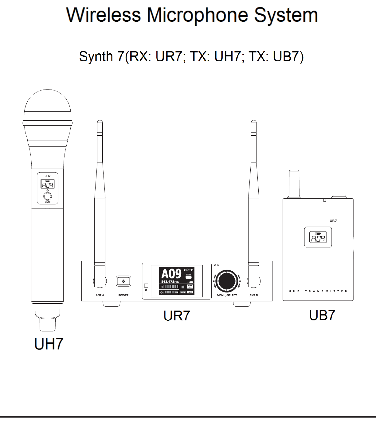
Congratulations on purchasing the Samson Synth 7 wireless system. The Synth 7 is the ideal solution for the active per-
former who needs a reliable, great sounding system for wireless applications.
Synth 7 system features all-metal components with easy-to-read displays and advanced menu functions for
seamless operation. The Synth 7 comes in five configurations. The vocal handheld system includes the UH7 handheld transmitter
with a Q8 dynamic microphone capsule. The UB7 belt pack system can be configured with either the SE10 earset microphone, LM10
lavalier microphone, QV vocal headset microphone or a ¼” instrument cable. For travel or permanent installation, the Synth 7 includes a
standard 19” rackmount kit.
In these pages, you’ll find a detailed description of the features of the Synth 7 wireless system, step-by-step
instructions for its setup and use, as well as full specifications. If your wireless system was purchased in the
United States, you’ll also find a warranty card enclosed—don’t forget to fill it out and mail it in so that you can
receive online technical support and so that we can send you updated information about this and other Samson
products in the future. Also, be sure to check out our website (www.samsontech.com) for complete information
about our full product line.
We recommend you keep the following records for reference, as well as a copy of your sales receipt.
Receiver Serial number: _________________________________________
Transmitter Serial number: ______________________________________
Date of purchase: ______________________________________________
Dealer name: __________________________________________________
With proper care and maintenance, your Synth 7 wireless system will operate trouble-free for many years.
Should your wireless system ever require servicing, a Return Authorization (RA) number must be obtained
before shipping your unit to Samson. Without this number, the unit will not be accepted. Please call Samson at
1-800-3SAMSON (1-800-372-6766) for an RA number prior to shipping your unit. Please retain the original
packing materials and, if possible, return the unit in its original carton. If your Synth 7 system was purchased
outside of the United States, contact your local distributor for warranty details and service information.
• Professional true-diversity UHF wireless systems
• Scan Mode and on screen spectrum analyzer finds optimal channels for interference-free performance
• Pilot Tone Squelch/Auto Mute function eliminate RF noise when the transmitter is muted
• Increased dynamic range to handle the hottest inputs
• Full-color receiver LCD
• Transmitter LCD indicates battery level and channel number
• Transmitter offers up to 15 hours of continuous operation on two AA batteries
• 300-foot operating range
• All-metal, rack mountable components ensure roadworthy durability
Features
Quick Start
In order for your wireless system to work correctly, both the receiver and transmitter must be set to the same
channel.
FREQ:
518-546.9MHz
SR266 Receiver
Tested To Comply With
FCC Standards
For Home Or Oce Use
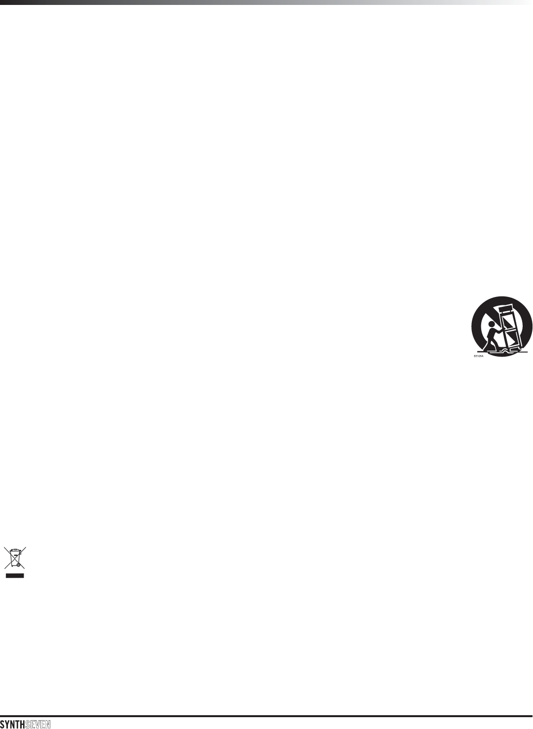
Set up the receiver:
Physically place the UR7 receiver where it will be used. The general rule of thumb is to maintain “line of sight”
between the receiver and transmitter so that the person using or wearing the transmitter can see the receiver.
Connect and position the antennas vertically.
Connect the included power adapter to an outlet.
Connect the UR7 receiver output jack to the microphone or line level input of a mixer or
amplifier using the balanced XLR output or unbalanced ¼” line level output.
Setting the receiver channel - When using a single system, set the receiver by using the Frequency Select menu.
When using multiple Synth 7 systems, use the Group & Channel menu so that each system should be assigned
to the same group in order to maximize the number of compatible channels
Single System Setup
Press and hold the power button to turn on the UR7 receiver. The receiver display will light.
Press the Menu/Select button to enter the Main Menu. Rotate the Menu/Select encoder to highlight
FREQUENCY SELECT and press the MENU/SELECT button.
Scroll down to highlight SCAN SPECTRUM and press the MENU/SELECT button. The receiver will scan the
wireless spectrum and choose an available channel.
Main Menu
Group & Channel
Frequency Setup
Audio Setup
Advanced Setup
Back
Frequency Select
518.000MHz
Scan Spectrum
IR Set
Back
Frequency Select
531.350MHz
Scan Spectrum
IR Set
Back
Scan Spectrum
531.350MHz CH F05
Quick Start
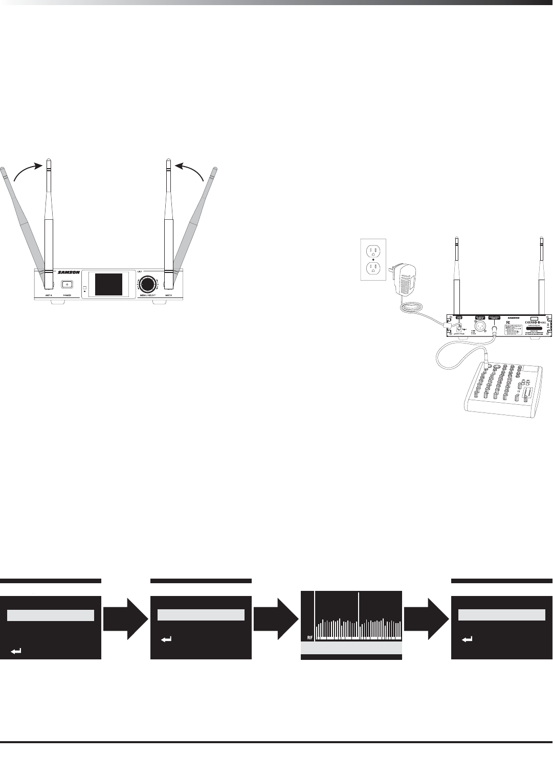
Multiple System Setup
Press and hold the power button to turn on the UR7 receiver.
Press the Menu/Select button to enter the Main Menu. Rotate the Menu/Select encoder to highlight GROUP &
CHANNEL and press the MENU/SELECT button to enter the menu.
Set each receiver to the same Group. Select GROUP and press the MENU/SELECT button. The Group letter
will start to flash. Rotate the MENU/SELECT encoder until you have selected the desired group and press the
MENU/SELECT button to set the receiver Group.
Select GROUP SCAN and press the MENU/SELECT button. The UR7 receiver will scan the selected Group for
an available channel.
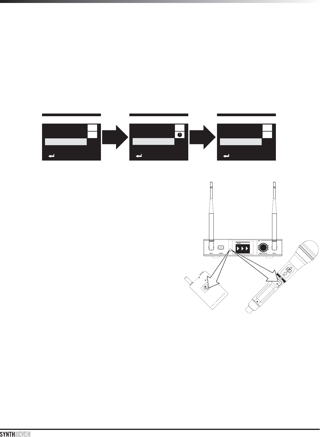
Set the transmitter:
Install two fresh AA batteries into the UB7 belt pack or UH7
handheld transmitter. Press and hold the power button to turn
on the transmitter.
On the UR7 receiver scroll down to IR SET and press the
MENU/SELECT button.
Position the transmitter about 6-12” (15-30 cm) from the front
of the UR7 receiver with the transmitter’s IR window facing
the IR transmitter on the front panel of the receiver. The UH7
transmitter IR window is inside the battery compartment. The IR
windows on the UB7 is next to the LCD display.
When the transmission is complete, select BACK or press
the power button on the UR7 receiver to return to the main
performance display.
Once a transmitter and receiver pair is set, leave the transmitter
powered on and locked before scanning the group for the next available channel. This will prevent the receiver
from selecting a channel that will cause interference.
Set the performance level
Speak or sing into the microphone, or if you are using the transmitter with a connected instrument, play the
instrument at normal performance level. Slowly raise the volume of your amplifier or mixer until the desired level
is reached.
If you find the system has noticeable dropouts, reduced overall working range, or unexpected noise bursts,
change the operating channel of the system using the steps above.
01
B
Group & Channel
Group
Channel
Group Scan
IR Set
Back
05
B
Group & Channel
Group
Channel
Group Scan
IR Set
Back
B
Group & Channel
Group
Channel
Group Scan
IR Set
Back
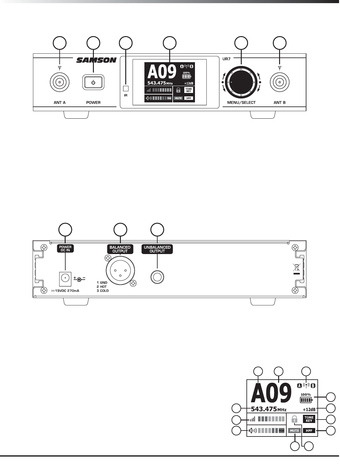
UR7 Receiver Callouts
A. Group
B. Channel
C. Active Antenna Indicator
D. Operating Frequency
E. RF Signal Meter
F. Audio Meter
G. Transmitter Battery Indicator
H. Receiver Audio Output Level
I. Tone Key Active Indicator
J. High Pass Filter Indicator
K. Receiver Lock
L. Transmitter Mute Indicator
1. Antennas Jacks - The BNC antenna jacks allow full rotation for optimum placement. In normal operation,
both antennas should be placed in a vertical position.
2. POWER Switch - Press and hold this to power the receiver on or off. A quick press of the button will move
back through the menus.
3. IR Transmitter - During “IR SET” an infrared code (similar to selecting a channel with a TV remote) is used to
set the transmitter channel.
4. Color LCD - Displays transmitter and receiver settings and performance data.
5. MENU/SELECT Control - This rotary encoder control knob/button is used to control and set menu functions and
parameters.
1123 4 5
FREQ:
518-546.9MHz
SR266 Receiver
Tested To Comply With
FCC Standards
For Home Or Oce Use
678
6. DC Input - Connect the supplied power adapter here. WARNING: Do not substitute any other kind of power
adapter. Doing so can cause severe damage to the UR7 and will void your warranty.
7. XLR BALANCED OUTPUT - Electronically balanced, microphone-level output.
8. ¼” UNBALANCED OUTPUT - Unbalanced high impedance instrument-level output.
A B C
G
HD
E
F
I
J
KL
LCD Display
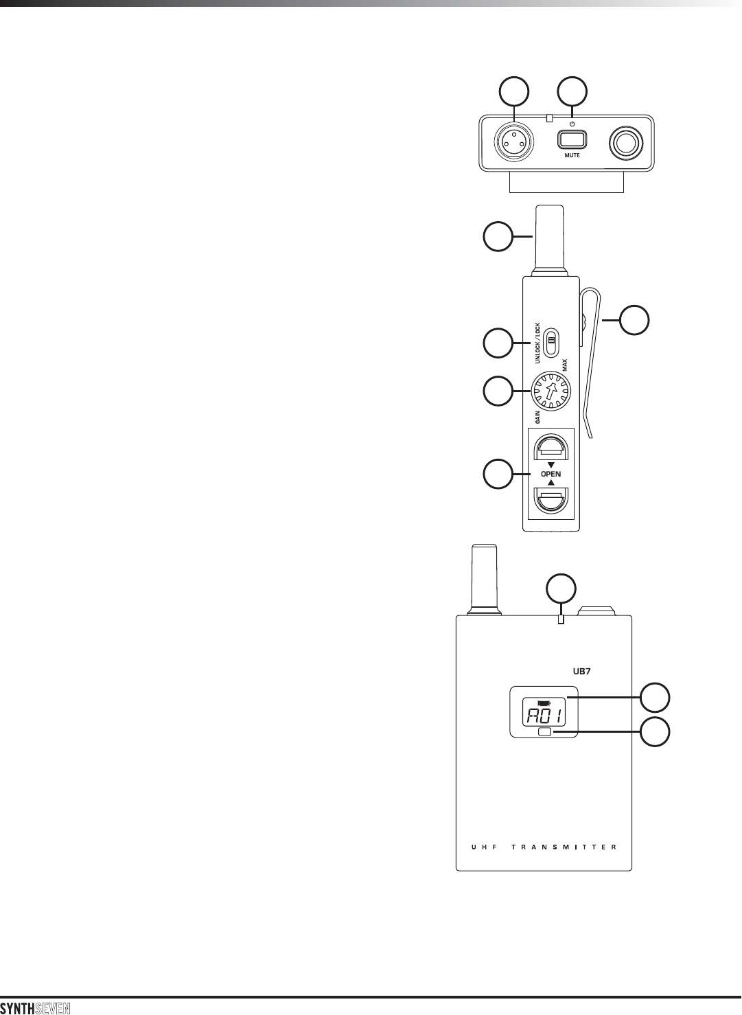
UB7 Callouts
1. Input Connector - Connect the input device via the
mini-XLR connector.
2. Power/Mute Switch - Press and hold to turn the unit
on or off. Press and release to mute or unmute the
transmitter.
3. Antenna - Permanently attached transmitter antenna.
4. Belt Clip - Use this clip to fasten transmitter to a
belt or guitar strap.
5. UNLOCK/LOCK Switch - Locking the system controls
prevents accidental muting or channel adjustment
during performance.
6. Input GAIN Control - This control adjusts the
transmitter input sensitivity to work with microphone
and instruments input signals. For optimal
performance set the input GAIN control to where
you see the UR7 PEAK indicator start to light under
high levels, then turn down slowly until the PEAK
light stops lighting or only occasionally flashes
during the loudest input each channel will see
7. Battery Holder - Insert two standard AA (LR6)
batteries here, being sure to observe the plus
and minus polarity markings shown. Although
rechargeable Ni-Cad batteries can be used, they
do not supply adequate current for more than four
hours.
WARNING: Do not insert the batteries backwards; doing
so can cause severe damage to the UR7 and will void
your warranty.
8. Status Indicator - This LED lights green when the
transmitter is powered, and lights red when the
transmitter is muted.
9. LCD Display - Displays the group, channel and
battery level information.
10. IR Lens - This window is used to capture the infrared
signal sent from the UR7 during the IR SET to
channelize the transmitter.
1 2
5
6
7
3
4
8
9
10
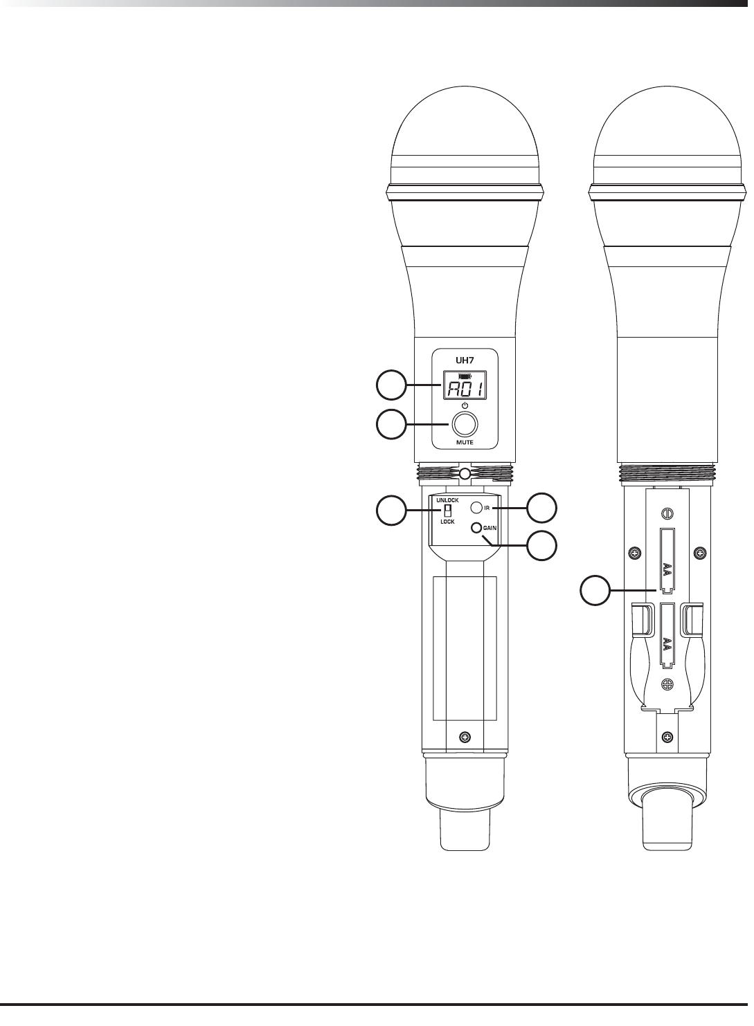
1. LCD Display - Displays the current group,channel and
battery level information.
2. Power/Mute Switch - Press and hold to turn the unit
on or off. Press and release to mute or un-mute the
transmitter.
3. UNLOCK/LOCK Switch - Locking the system controls
prevents accidental muting or channel adjustment
during performance.
4. Battery Holder - Open the battery holder by pressing
the tab and lifting the cover. Insert two standard
AA (LR6) batteries here, being sure to observe the
plus and minus polarity markings shown. Although
rechargeable Ni-Cad batteries can be used, they
do not supply adequate current for more than four
hours.
WARNING: Do not insert the batteries backwards; doing
so can cause severe damage to the UH7 and will void
your warranty.
5. IR Lens - This window is used to capture the infra-
red signal sent from the UR7 during the IR SET to
channelize the transmitter. The battery cover must
be open and the IR Lens facing towards the receiver
to load the selected channel.
6. Input GAIN Button - This control adjusts the transmit-
ter input sensitivity. Press to set the gain setting.
For optimal performance,set the input GAIN control
to where you see the UR7 PEAK indicator start to
light under high levels, then turn down until the
PEAK light stops lighting.
UH7 Callouts
1
2
34
6
5
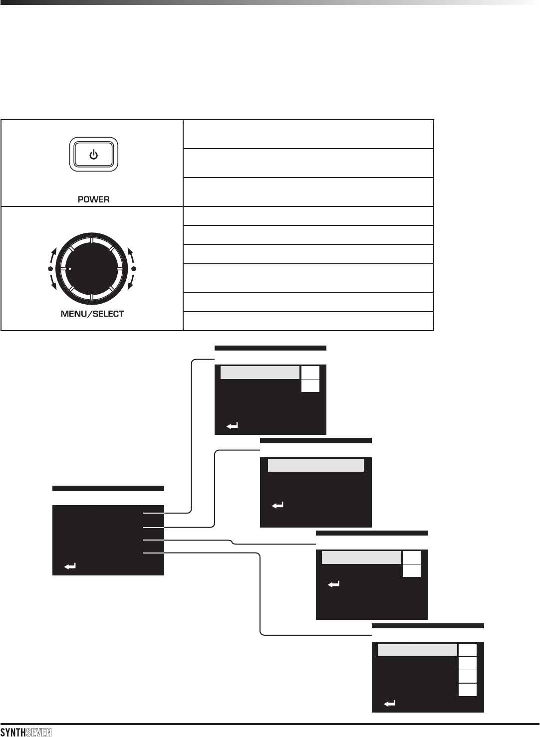
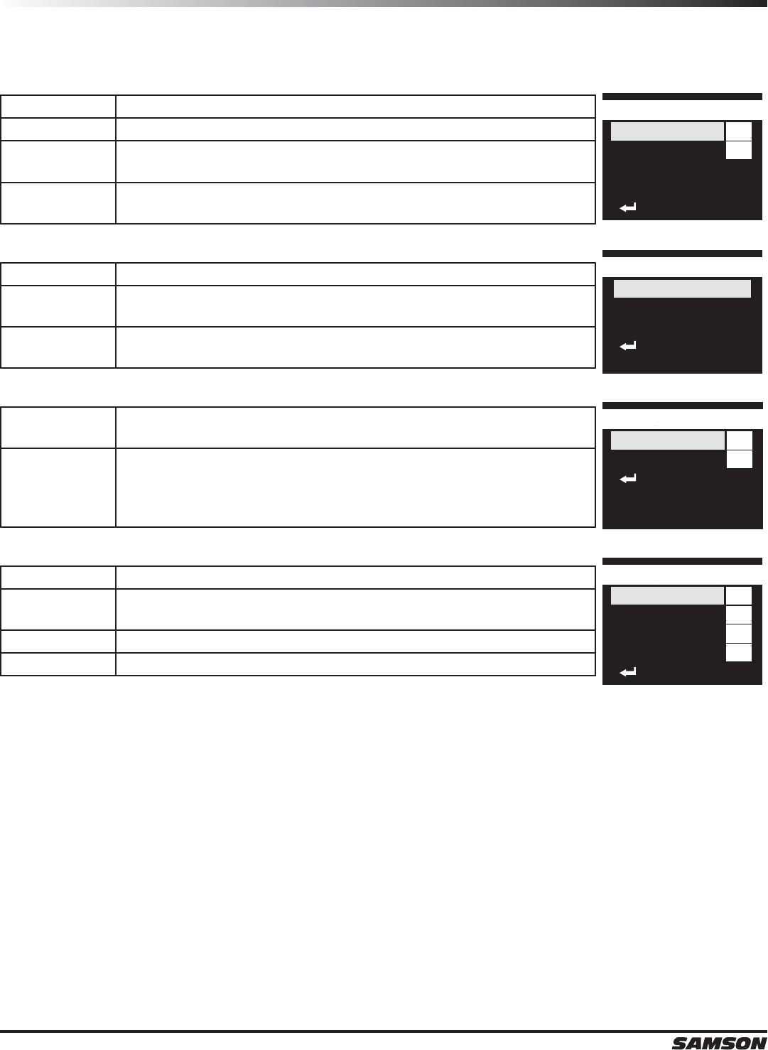
The UR7 receiver features a user friendly operating menu, with extensive features and adjustable parameters.
This enables the receiver and transmitter to be quickly and easily set up for performance.
Controls
POWER Button Press and hold switches the receiver on and off
Short press cancels an entry and returns to the
current menu
Short press moves back through the menus.
MENU/SELECT Encoder and Button Press to enter the menus
Enters a sub-menu
Selects a parameter to be adjusted
Confirms and stores a setting and returns to the
current menu
Rotate to cycle through available menu selections
Rotate to cycle through available parameter
Main Menu
Group & Channel
Frequency Setup
Audio Setup
Advanced Setup
Back
01
A
Group & Channel
Group
Channel
Group Scan
IR Set
Back
Frequency Select
632.000MHz
Scan Spectrum
IR Set
Back
OFF
01
Audio Setup
Audio Level
HPF
Back
01
LOW
Advanced Setup
Squelch
Tone Key
Contrast
Lock
Back
ON
ON
Operating Menus
UR7 Operating Menu
Menu Parameters
Group & Channel
Group Manually adjusts the operating Group
Channel Manually adjusts the channel with the selected Group
Group Scan Scans the current selected group channels and selects the cleanest
signal to use for optimal performance
IR Set Sends the group and channel information to the UH7 and UB7
transmitters via the infrared set.
Frequency Select
Frequency Manually adjust the operating frequency of the UR7 receiver.
Scan Spectrum Scans the entire frequency band of the UR7 receiver and selects the
cleanest signal to use for optimal performance.
IR Set Sends the operating frequency information to the UH7 and UB7
transmitters via the infrared set.
Audio Setup
Audio Level Sets the level of the audio signal being output through both the
balanced and unbalanced output jacks on the rear panel.
HPF
Enables a high pass filter on the audio output. This is useful when
using the receiver with a handheld microphone to reduce lower
frequencies that you do not want the microphone to pick up. It is
useful for removing stage rumble.
Advanced Setup
Squelch Adjusts the squelch threshold
Tone Key Enables or disables the Tone Key. This is useful when setting up the
system to. During normal operation the Tone Key should be enabled.
Contrast Adjusts the contrast of the receiver display.
Lock Locks the controls of the receiver.
01
A
Group & Channel
Group
Channel
Group Scan
IR Set
Back
Frequency Select
632.000MHz
Scan Spectrum
IR Set
Back
OFF
01
Audio Setup
Audio Level
HPF
Back
01
LOW
Advanced Setup
Squelch
Tone Key
Contrast
Lock
Back
ON
ON
Group & Channel Menu
01
A
Group & Channel
Group
Channel
Group Scan
IR Set
Back
01
B
Group & Channel
Group
Channel
Group Scan
IR Set
Back
01
B
Group & Channel
Group
Channel
Group Scan
IR Set
Back
02
B
Group & Channel
Group
Channel
Group Scan
IR Set
Back
01
B
Group & Channel
Group
Channel
Group Scan
IR Set
Back
05
B
Group & Channel
Group
Channel
Group Scan
IR Set
Back
B
Group & Channel
Group
Channel
Group Scan
IR Set
Back
05
B
Group & Channel
Group
Channel
Group Scan
IR Set
Back
IR SetIR SetIR Set IR SetIR SetIR Set IR SetIR SetIR Set
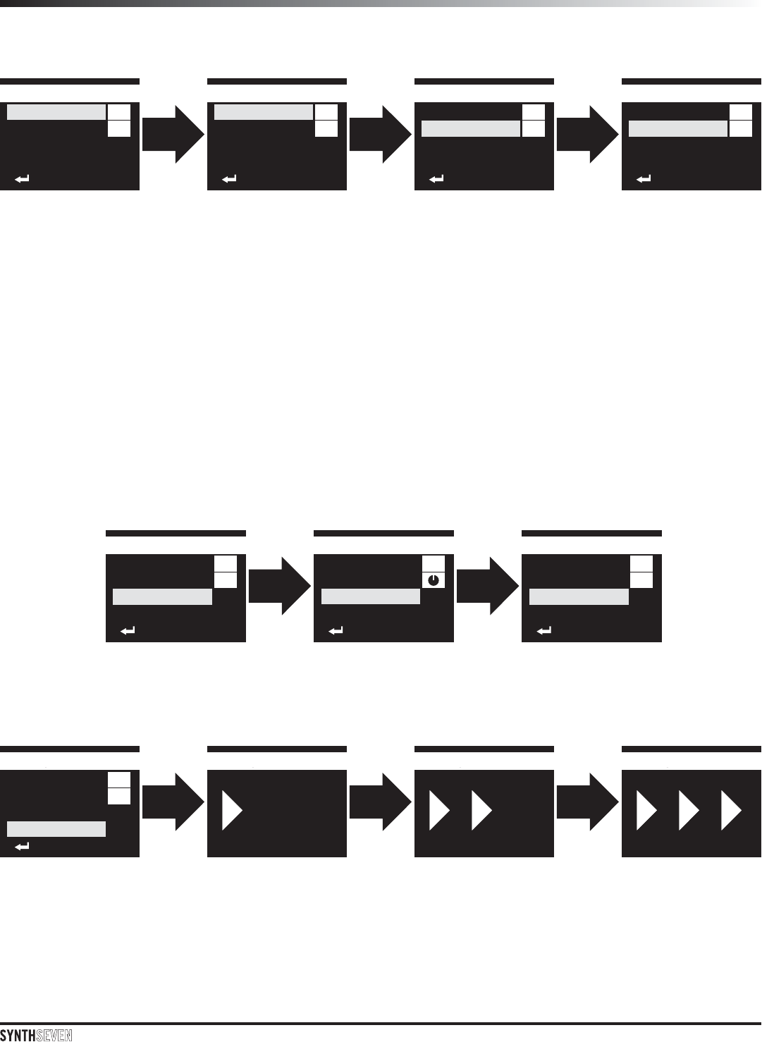
From the main performance page, press the MENU/SELECT button to enter the Main Menu.
With GROUP & CHANNEL highlighted, press the MENU/SELECT button to enter the GROUP & CHANNEL sub-
menu.
Setting Group and Channel
Rotate the cursor to select the GROUP parameter.
Press the MENU/SELECT button to adjust the setting.
Rotate the MENU/SELECT knob to adjust the group letter.
Press the MENU/SELECT button to confirm and store the setting or press the POWER button to cancel the
selection and move back to the GROUP & CHANNEL sub-menu.
Rotate the cursor to select the CHANNEL parameter.
Press the MENU/SELECT button to adjust the setting.
Rotate the MENU/SELECT knob to adjust the channel number.
Press the MENU/SELECT button to confirm and store the setting or press the POWER button to cancel the
selection and move back to the GROUP & CHANNEL sub-menu.
Scan the Group for a clear channel
Rotate the cursor to select the SCAN GROUP parameter.
Press the MENU/SELECT button to activate the scan function.
Set the transmitter group and channel
Rotate the cursor to select the IR SCAN parameter.
Press the MENU/SELECT button to active the IR SET function. While the IR SET is in progress, position the
transmitter about 6-12” (15-30 cm) from the front of the UR7 receiver with the transmitter’s IR window facing
the IR transmitter on the front panel of the receiver.
IR SetIR SetIR Set IR SetIR SetIR Set IR SetIR SetIR SetFrequency Select
518.000MHz
Scan Spectrum
IR Set
Back
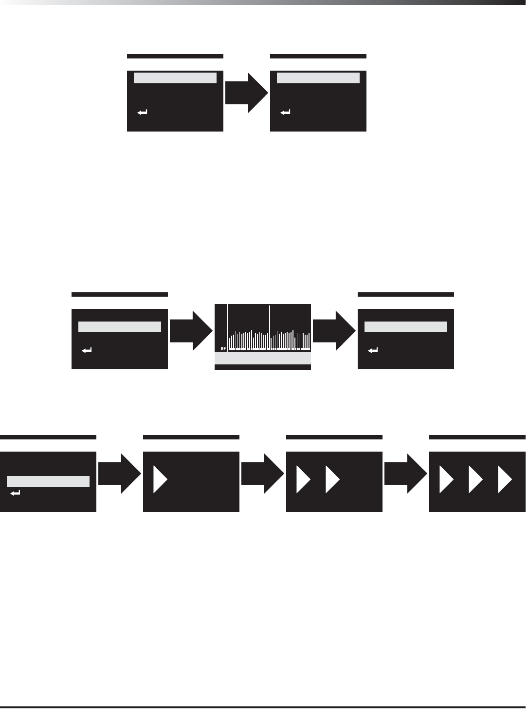
Frequency Select Menu
From the main performance page, press the MENU/SELECT Button to enter the Main Menu.
With FREQUENCY SETUP highlighted, press the MENU/SELECT button to enter the FREQUENCY SETUP sub-
menu.
Setting the Operating Frequency
Rotate the cursor to select the Frequency parameter.
Press the MENU/SELECT button to adjust the setting.
Rotate the MENU/SELECT knob to adjust the performance frequency.
Press the MENU/SELECT button to confirm and store the setting or press the POWER button to cancel the
selection and move back to the FREQUENCY SETUP sub-menu.
Frequency Select
518.000MHz
Scan Spectrum
IR Set
Back
Frequency Select
546.850MHz
Scan Spectrum
IR Set
Back
Scan the frequency band for a clean channel
Rotate the cursor to select the SCAN SPECTRUM parameter.
Press the MENU/SELECT button to activate the scan function.
Set the transmitter group and channel
Rotate the cursor to select the IR SCAN parameter.
Press the MENU/SELECT button to active the IR SET function. While the IR SET is in progress, position the
transmitter about 6-12” (15-30 cm) from the front of the UR7 receiver with the transmitter’s IR window facing
the IR transmitter on the front panel of the receiver.
Frequency Select
518.000MHz
Scan Spectrum
IR Set
Back
Frequency Select
531.350MHz
Scan Spectrum
IR Set
Back
Scan Spectrum
531.350MHz CH F05
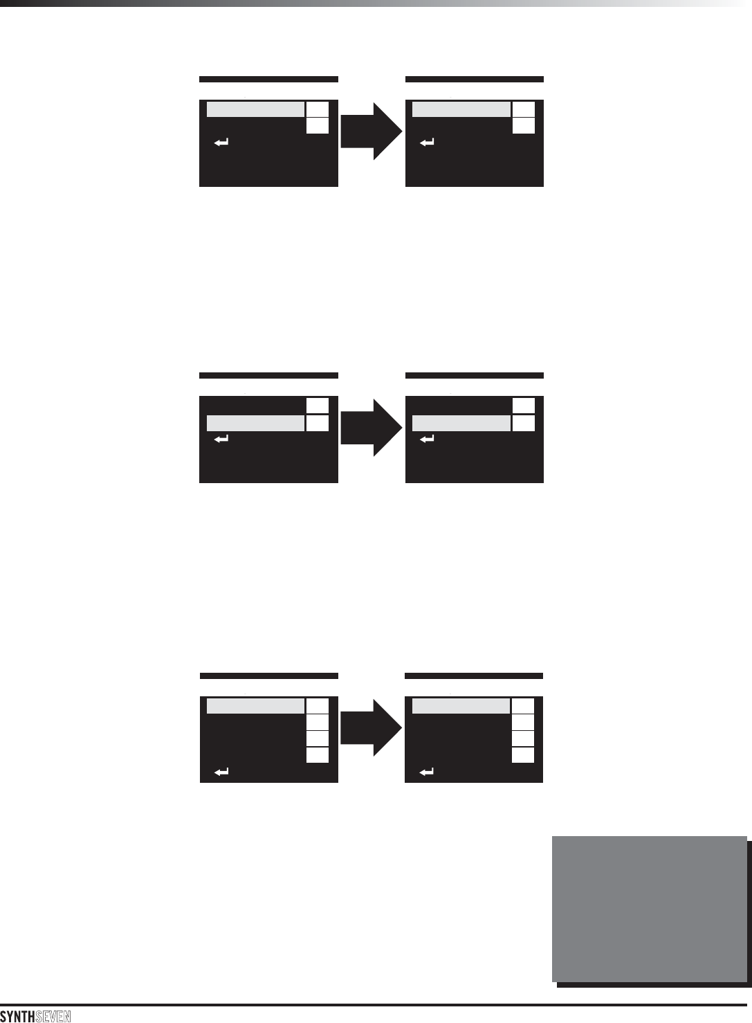
Audio Setup
From the main performance page, press the MENU/SELECT Button to enter the Main Menu.
With AUDIO SETUP highlighted, press the MENU/SELECT button to enter the AUDIO SETUP sub-menu.
Setting the Audio Level
Rotate the cursor to select the AUDIO LEVEL parameter.
Press the MENU/SELECT button to adjust the setting.
Rotate the MENU/SELECT knob to adjust the output level setting.
Press the MENU/SELECT button to confirm and store the setting or press the POWER button to cancel the
selection and move back to the AUDIO LEVEL sub-menu.
OFF
01
Audio Setup
Audio Level
HPF
Back
OFF
12
Audio Setup
Audio Level
HPF
Back
OFF
01
Audio Setup
Audio Level
HPF
Back
ON
12
Audio Setup
Audio Level
HPF
Back
Enabling the High Pass Filter
Rotate the cursor to select the HPF parameter.
Press the MENU/SELECT button to adjust the setting.
Rotate the MENU/SELECT knob to turn the HPF On or OFF.
Press the MENU/SELECT button to confirm and store the setting or press the POWER button to cancel the
selection and move back to the AUDIO LEVEL sub-menu.
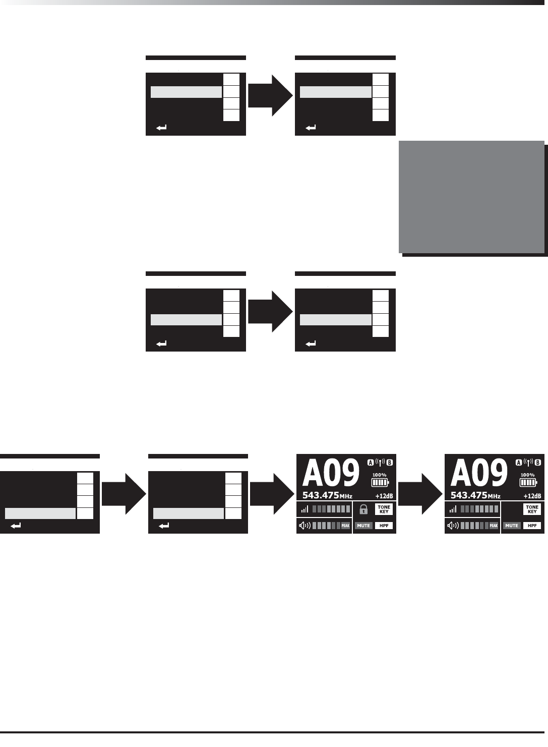
Advanced Setup
From the main performance page, press the MENU/SELECT Button to enter the Main Menu. With ADVANCED
SETUP highlighted, press the MENU/SELECT button to enter the ADVANCED SETUP sub-menu.
Adjust the Squelch Threshold
Rotate the cursor to select the SQUELCH parameter. Press the MENU/SELECT
button to adjust the setting. Rotate the MENU/SELECT knob to adjust the
threshold level. Press the MENU/SELECT button to confirm and store the setting.
Press the POWER button to cancel the selection and move back to the ADVANCED
LEVEL sub-menu.
The Squelch threshold setting is
helpful in increasing the audio
reception between the receiver
and transmitter when there is
RF interference. As the squelch
threshold is increased, the
overall range is reduced. Always
start with the squelch set to the
minimum setting.
01
LOW
Advanced Setup
Squelch
Tone Key
Contrast
Lock
Back
ON
ON
01
MID
Advanced Setup
Squelch
Tone Key
Contrast
Lock
Back
ON
ON
Advanced Setup
The Tone Key is an inaudible fre-
quency that is transmitted along
with the audio signal. It assists in
reducing audio interference from
other RF devices. When trouble-
shooting audio issues, it may be
helpful to turn the tone key off.
For best performance, it is recom-
mended to always have the Tone
Key activated.
01
LOW
Advanced Setup
Squelch
Tone Key
Contrast
Lock
Back
ON
ON
01
LOW
Advanced Setup
Squelch
Tone Key
Contrast
Lock
Back
OFF
ON
01
LOW
Advanced Setup
Squelch
Tone Key
Contrast
Lock
Back
ON
ON
10
LOW
Advanced Setup
Squelch
Tone Key
Contrast
Lock
Back
OFF
ON
Enabling the Tone Key
Rotate the cursor to select the TONE KEY parameter. Press the MENU/SELECT
button to adjust the setting. Rotate the MENU/SELECT knob to turn the
TONE KEY on or off. Press the MENU/SELECT button to confirm and store the
setting. Press the POWER button to cancel the selection and move back to the
ADVANCED LEVEL sub-menu.
Adjust the Display Contrast
Rotate the cursor to select the CONTRAST parameter. Press the MENU/SELECT button to adjust the setting.
Rotate the MENU/SELECT knob to adjust the contrast level. Press the MENU/SELECT button to confirm and
store the setting. Press the POWER button to cancel the selection and move back to the ADVANCED LEVEL sub-
menu.
Lock the receiver controls
Rotate the cursor to select the LOCK parameter. Press the MENU/SELECT button to adjust the setting. Rotate
the MENU/SELECT knob to enable the receiver Lock. Press the MENU/SELECT button to confirm and store the
setting. Press the POWER button to cancel the selection and move back to the ADVANCED LEVEL sub-menu.
If the Lock is activated, the receiver must be unlocked before being able to adjust any parameters. To unlock
the receiver, press and hold the MENU/SELECT button until the LOCK icon is flashing. Rotate the MENU/
SELECT knob until the icon shows unlock, then press the MENU/SELECT button to confirm.
01
LOW
Advanced Setup
Squelch
Tone Key
Contrast
Lock
Back
ON
OFF
10
LOW
Advanced Setup
Squelch
Tone Key
Contrast
Lock
Back
OFF
ON
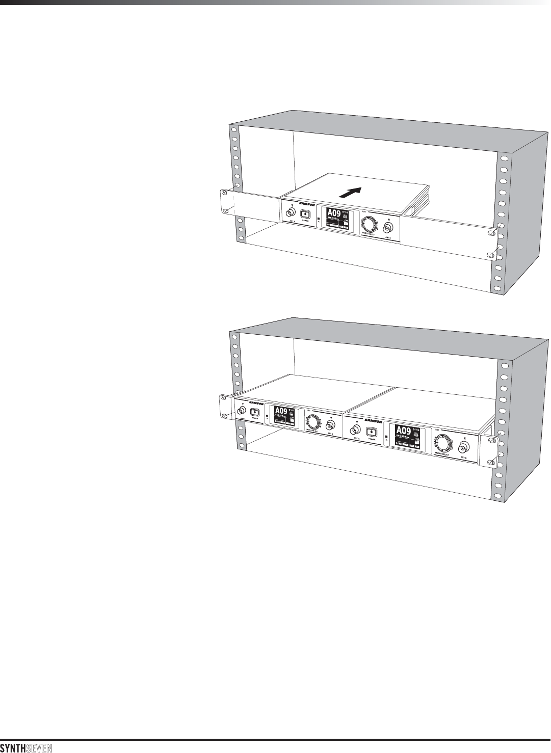
The UR7 receiver can be installed into a standard 19” rack for transport or permanent installation using the
included rack ears.
Affix the included rack ears to each side of
the UR7 receiver. Secure the rack ears in
place using the screws provided.
Position the UR7 receiver into an available
rack space and slide in until the rack ears
are touching the rails of the rack case and
are aligned with the rack rail holes.
Mount the receiver into the rack using the
appropriate size rack screws (not included).
To ensure equal tension and balance when
installing the receiver, you should secure
screws in a crisscross pattern of opposite
corners: top left -> bottom right -> top right
-> bottom left.
A dual receiver rack mount kit (RKUR7) is
available to mount two UR7 receivers in one
rack space. The kit includes two short rack
ears, a center connection piece, and a rear
joint plate.
Rack Mounting
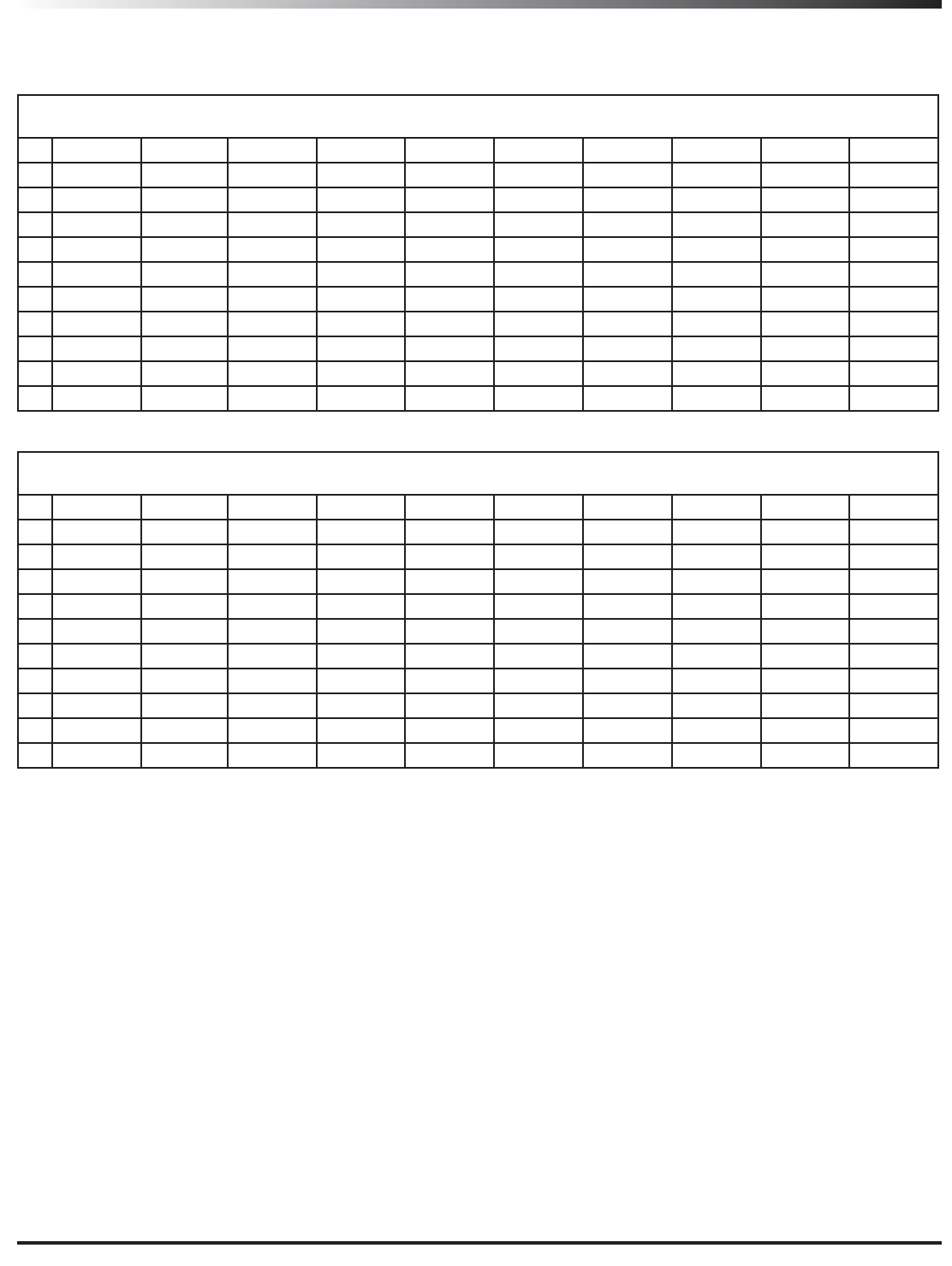
Channel Plans
Group C
638-666MHz
A B C` D E F G H I J
1 638.000 638.200 638.225 638.300 638.425 638.950 639.000 639.200 639.225 639.300
2 640.525 640.725 640.750 640.825 640.950 641.475 641.525 641.725 641.750 641.825
3 643.150 643.350 643.375 643.450 643.575 644.100 644.150 644.350 644.375 644.450
4 645.875 646.075 646.100 646.175 646.300 646.825 646.875 647.075 647.100 647.175
5 648.700 648.900 648.925 649.000 649.125 649.650 649.700 649.900 649.925 650.000
6 651.650 651.850 651.875 651.950 652.075 652.600 652.650 652.850 652.875 652.950
7 654.725 654.925 654.950 655.025 655.150 655.675 655.725 655.925 655.950 656.025
8 657.925 658.125 658.150 658.225 658.350 658.875 658.925 659.125 659.150 659.225
9 661.250 661.450 661.475 661.550 661.675 662.200 662.250 662.450 662.475 662.550
10 664.700 664.900 664.925 665.000 665.125 665.650 665.700 665.900 665.925 666.000
Group I
518-546.9MHz
A B C` D E F G H I J
1 518.000 518.200 518.225 518.300 518.425 518.950 520.000 520.200 520.225 520.300
2 521.025 521.225 521.250 521.325 521.450 521.975 522.775 522.975 523.000 523.075
3 524.100 524.300 524.325 524.400 524.525 525.050 525.600 525.800 525.825 525.900
4 527.225 527.425 527.450 527.525 527.650 528.175 528.475 528.675 528.700 528.775
5 530.400 530.600 530.625 530.700 530.825 531.350 531.400 531.600 531.625 531.700
6 533.600 533.800 533.825 533.900 534.025 534.550 534.350 534.550 534.575 534.650
7 536.850 537.050 537.075 537.150 537.275 537.800 537.350 537.550 537.575 537.650
8 540.150 540.350 540.375 540.450 540.575 541.100 540.400 540.600 540.625 540.700
9 543.475 543.675 543.700 543.775 543.900 544.425 543.475 543.675 543.700 543.775
10 546.850 547.050 547.075 547.150 547.275 547.800 546.600 546.800 546.825 546.900
Group F*
606-634 MHz
A B C` D E F G H I J
1 606.000 606.200 606.225 606.300 606.425 606.950 607.000 607.200 607.225 607.300
2 608.525 608.725 608.750 608.825 608.950 609.475 609.525 609.725 609.750 609.825
3 611.150 611.350 611.375 611.450 611.575 612.100 612.150 612.350 612.375 612.450
4 613.875 614.075 614.100 614.175 614.300 614.825 614.875 615.075 615.100 615.175
5 616.700 616.900 616.925 617.000 617.125 617.650 617.700 617.900 617.925 618.000
6 619.650 619.850 619.875 619.950 620.075 620.600 620.650 620.850 620.875 620.950
7 622.725 622.925 622.950 623.025 623.150 623.675 623.725 623.925 623.950 624.025
8 625.925 626.125 626.150 626.225 626.350 626.875 626.925 627.125 627.150 627.225
9 629.250 629.450 629.475 629.550 629.675 630.200 630.250 630.450 630.475 630.550
10 632.700 632.900 632.925 633.000 633.125 633.650 633.700 633.900 633.925 634.000
* Not for use in the USA and Canada. For questions regarding available channels in your area contact your local Samson distributor.
System
Working Range 300’ (100m) line of sight
Audio Frequency Response 50 Hz - 15 kHz
T.H.D. (Overall) <1% (@AF 1 kHz, RF 46 dBu)
Dynamic Range >100 dB A-weighted
Signal to Noise >90 dB
Operating Temperature –10°Cto +°C
Tone Key Frequency 32.768KHz
UB7 Belt Pack Transmitter
Input Connector
Input Impedance
Input Gain Range
RF Power
Power Requirements
Battery Life
Dimensions (HxLxD)
Weight
Mini-XLR (P3)
1MΩ
38 dB
E#N
Two AA (LR6) alkaline batteries
Up to 15 hours
2.4” x 0.78” x 3.5” / 62mm x 20mm x 90mm
5oz / 139.4g
UH7 Handheld Transmitter
Microphone Element
Input Gain Range
RF Power
Power Requirements
Battery Life
Dimensions (HxØ)
Weight
Q8 Dynamic
28 dB
E#N
Two AA (LR6) alkaline batteries
Up to 15 hours
10.5” x 2.2” / 266mm x 55mm
11oz / 310.2g
UR7 Receiver
Audio Output Level Unbalanced+14 dBu / Balanced +9 dBu
Audio Output Impedance Unbalanced 810 Ohms / Balanced 240 Ohms
Sensitivity -100 dBm / 30 dB sinad
Image Rejection >50 dB
Operating Voltage: 15V
Dimensions (LxWxH) 8.5” x 1.8” x 7.4” / 215mm x 45mm x 189mm
Weight: 3.1lb / 1.4kg
Specifications