Sam Radios CM300W 3G IP Mobile Radio User Manual CM 300 User Guide
Sam Radios Ltd. 3G IP Mobile Radio CM 300 User Guide
Users Manual
SAMCOM
CM-300
3G IP Mobile Radio
User Guide
INTRODUCTION
Thank you for purchasing the SAMCOM CM-300 3G IP mobile
radio.
We focus on ease of use, reliability and value for money. We
sincerely hope our products meet your expectations.
Main Features
- Compact, simple but rugged design
- Crisp, clear and high quality sound
- Supports 2G and 3G WCDMA
- KENWOOD RJ-45 type microphone connector
- Firmware upgradable, allowing new features to be added
when available
- Built in 1W speaker, providing clear speech even in the
noisiest environments
- Over The Air Programming (OTAP) of contact lists
FCC Statement
Any changes or modifications not expressly approved by the
party responsible for compliance could void the user’s
authority to operate the equipment.
This device complies with part 15 of the FCC rules. Operation
is subject to the following two conditions:
(1) This device may not cause harmful interference;
(2) This device must accept any interference received,
including interference that may cause undesired operation.
IMPORTANT NOTE:
FCC Radiation Exposure Statement:
This equipment complies with FCC radiation exposure limits
set forth for an uncontrolled environment. This equipment
should be installed and operated with minimum distance 20cm
between the radiator & your body. This transmitter must not be
co-located or operating in conjunction with any other antenna
or transmitter.
Note: This equipment has been tested and found to comply
with the limits for a Class B digital device, pursuant to Part 15
of the FCC rules.
These limits are designed to provide reasonable protection
against harmful interference in a residential installation.
This equipment can generate, use and radiate radio frequency
energy and, if not installed and used in accordance with
instruction, may cause harmful interference to radio
communications. However, there is no guarantee that
interference will not occur in a particular installation. If this
equipment does cause harmful interference to radio or
television reception, which can be determined by turning the
equipment OFF and ON, the user will encouraged to try to
correct the interference by one or more of the following
measures:
- Reorient or relocate the receiver antenna.
- Increase the separation between the equipment and receiver.
- Connect the equipment into an outlet on a circuit different
from that to which the receiver is connected.
- Consult the dealer or an experienced radio/TV technician for
help.
SAFETY INFORMATION
Please read this information before using your radio. Failure to
do so could result in personal injury, death, and/or damage to
your radio, accessories and/or other property.
Radio Care
● Do not use any parts or accessories not made specifically for
this radio.
● Ensure that the radio is used within the parameters for which
it was designed.
● Turn the radio OFF before connecting optional accessories.
Warning
Turn the radio OFF in the following locations:
● In explosive atmospheres (flammable gas, dust including
metallic & grain powders, etc).
● While taking on fuel or while parked near a fuel station.
● Near explosives or blasting sites.
● In aircraft or medical institutions.
● Near persons known to be wearing a pacemaker.
Caution
● Do not disassemble nor modify the radio for any reason.
● Do not transmit while touching the antenna terminal or any
exposed metallic parts of the aerial as this may result in burns.
● Please check and observe state laws regarding use while
driving.
End of Life Disposal
● When your radio can no longer be used, please ensure that
the unit is disposed of in an environmentally friendly way.

RADIO OVERVIEW
Package Includes:
1 radio unit
1 microphone speaker
1 mount bracket
1 power cable
1 GSM/WCDMA antenna
1 User guide
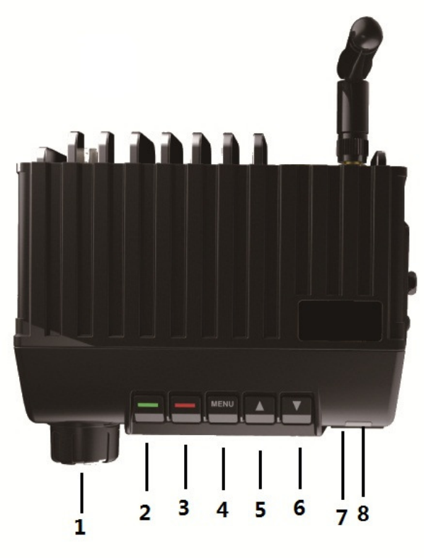
At a Glance
1 –On/Off/Volume Knob
Turns the radio ON or OFF, and adjusts the volume.
2 – Enter Button
Press this button to enter the menu functions and confirm your
selections.
3 – Exit Button
Press this button to cancel your selections and exit the menu
functions.
4 – Menu Button
Press this button to enter menu operation mode.
5 – Up Button
Press this button to select your desired menu functions.
6 – Down Button
Press this button to select your desired menu functions.
7 – Accessory Jack
Speaker Microphone and programming jack.
8 – LED Indicator
LED Blue flashing means searching for network.
LED Blue fast flashing means logging on to the network.
LED Blue slow flashing means logged on to the network.
LED Green permanent means receiving.
LED Orange means programming mode.
When pressing PTT button on the speaker microphone LED
RED means transmitting.
LED Red flashing means firmware updating mode.
GETTING STARTED
Mobile Installation
To install the mobile, select a safe, convenient location inside
your car that minimizes danger to your passengers and
yourself while the car is in motion. Consider installing the unit
at an appropriate position so that knees or legs will not strike it
during sudden braking of your car. Try to pick a well ventilated
location that is shielded from direct sunlight.
1. Install the mounting bracket in the car using the supplied
self-tapping screws and flat washers.
2. Position the mobile, then insert and tighten the supplied
hexagon SEMS screws.
Note: double check that all screws are tightened to prevent car
vibration from loosening the bracket or transceiver.
Determine the appropriate angle of the mobile, using the 3
screw hole positions on the side of the mounting bracket.
DC Power Cable Connection
The mobile can support both 12V and 24V car battery. Be sure
to use a 12V vehicle battery at least that has sufficient current
capacity. If the current to the mobile is insufficient, the display
may darken during transmitting.
1. Route the DC power cable supplied with the mobile
directly to the car’s battery terminals using the shortest path
from the mobile.
Note: the entire length of the cable must be dressed so it is
isolated from heat, moisture, and the engine secondary (high
voltage) ignition system cables.
2. After installing cable, in order to avoid the risk of damp,
please use heat-resistant tap to tie together with fuse box.
Don’t forget to reinforce whole cable.
3. In order to avoid the risk of short circuit, please cut down
connection with negative (-) of battery, then connect with
mobile.
4. Confirm the correct polarity of the connections, then
attach the power cable to the battery terminals; red connect to
the positive (+) terminal and black connects to the negative (-)
terminal.
Use the full length of the cable without cutting off excess even
if the cable is longer than required. In particular, never remove
the fuse holders from the cable.
5. Reconnect any wiring removed from the negative
terminal.
6. Connect the DC power cable to the mobile’s power
supply connector.
Press the connectors firmly together until the locking tab
clicks.
Programming Mode
To make the radio to enter programming mode, press the
Down button and turn on the radio, the LED will display
orange.
Firmware Updating Mode
To make the radio to enter firmware updating mode, press the
Menu button and turn on the radio, the LED will red flash.

SPECIFICATIONS
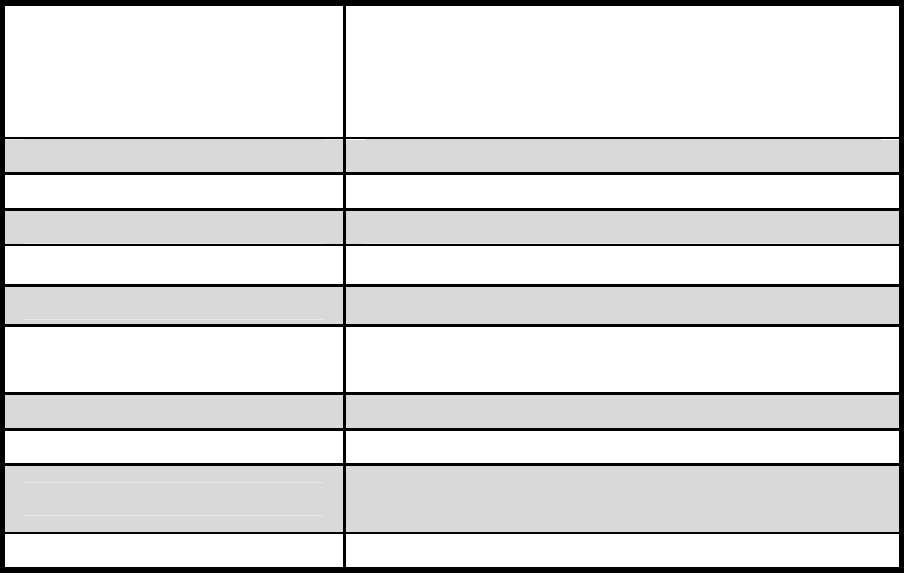
General
Frequency Range
GSM: 850MHz
PCS: 1900MHz
WCDMA Band 2: 1900MHz
WCDMA Band 5: 850MHz
Operating Voltage 9~24V DC
Dimensions 115 x 105 x 38mm
Weight with battery 280g
Operating Temperature
-30℃ to +50℃
Storage Temperature -40℃ to +70℃
Operating Current 5mA (-75dBm), 120mA (-75dBm), 780mA
(-104dBm)
Receiver Sensitivity -106dBm
Usage Condition 23~26dBm
Receiver Type -56-** u-blox7 engine, GLONASS L1
FDMA SBAS: WAAS, EGNOS, MSAS
Maximum Refresh Rate
10Hz
The above is correct at time of print, however SAMCOM Radio
Ltd reserves rights to update specifications as and when these
become available.
WARRANTY INFORMATION
Warranty Period
Radio: 1 year from date of purchase.
Battery Pack: 6 months from date of purchase.
Note: Please retain your receipt as your proof of purchase.
Warranty Exclusions
The warranty will not apply to the following:
Failure to provide a proof of purchase
Product has been modified or serial number has been
removed
If any damage results from the use of incompatible
accessories
Product fails because of misuse, abuse or inappropriate
use
Improper battery or antenna installation