Samsung Electro Mechanics SWL-2700M Mini PCI Card User Manual New Manual
Samsung Electro Mechanics Mini PCI Card New Manual
Contents
- 1. Test Setup
- 2. New Manual
New Manual
MagicLAN5 Utility
SWL-2700M/5300M
User’s Guide
SAMSUNG
2.4/5GHz
Wireless LAN
Networking
Soultions

Introduction
The MagicLan5 Utility is a user-mode utility designed to edit and add profiles for, as well as
display and diagnostics pertaining to a selected SWL-2700M/5300M minipci card (wireless
adapter).
See also:
• System Requirements
• Scan Available Networks
• Profile Management
• TCP/IP Configuration
System Requirements
• Laptop/ PC containing:
• 32-bit CardBus slot (or Desktop PC with PC Card-PCI
adapter)
• Mini PCI
• 32 MB memory or greater
• 300 MHz processor or higher
• Microsoft Windows 2000, Windows Millennium Edition,
Windows 98 Second Edition, Windows XP

Scan Available Networks
Click the Refresh button on the Wireless Networks tab to scan for available infrastructure and
ad hoc networks.
Connecting to a different network
• Highlight a network name and click the Configure button to connect an available netwo
rk. If no configuration profile exists for that network, the Profile Management windo
w opens to the General tab. Fill in the profile name and click OK to create the
configuration profile for that network.

Profile Management
Configure the wireless network adapter (wireless card) from the Wireless Networks tab of the
MagicLan5 Utility.
• Add a profile
• Edit a profile
• Switch to a different profile
• Remove a profile
The wireless network adapter works in either infrastructure mode (which uses an access point)
or ad hoc mode (a group of stations participating in the wireless LAN).

Create or Modify a Configuration Profile
To add a new configuration profile, click New on the Wireless Networks tab. To modify a
configuration profile, select the configuration from the Profile list and click the Modify button.
Profile Management:
• Edit the General tab.
• Edit the Security tab.
• Edit the Advanced tab.
To configure a profile for ad hoc or access point (infrastructure) mode, edit the Network Type
field on the Advanced tab.

Remove a Configuration Profile
1. Go to the Wireless Networks tab.
2. Select the profile to remove from the list of configuration profiles.
3. Click the Remove button.

Switching to a different configuration profile
1. To switch to a different profile, go to the Wireless Networks tab.
2. Click on the profile name in the Profile List.
3. Click the Activate button.
See also Scan Available Networks.

General Tab
In the MagicLan5 Utility, access the General tab by clicking Configure, New or Modify on the
Wireless Networks tab.
Edit the fields in the General tab to configure the configuration profile. Make sure to also edit the
Security and Advanced tabs.
Profile Name Identifies the configuration profile. This name must be
unique. Profile names are not case sensitive.
Network Names (SSID) The IEEE 802.11 wireless network name. This field
has a maximum limit of 32 characters.
Configure a SSID
See also:
• Configure a Profile for Ad Hoc Mode
• Configure a Profile for Access Point (Infrastructure) Mode

Ad Hoc Mode Profile Configuration
To configure a profile in ad hoc mode, change the Network Type in Advanced tab. For ad hoc
mode, modify the settings:
• Network Name (on General Tab)
• Transmit Power Level
• 802.11b Preamble (if using 802.11b)
• Wireless Mode When Starting an Ad Hoc Network
Make sure to also edit the General and Security tabs.

Infrastructure (Access Point) Mode Profile Configuration
To configure a profile in infrastructure (access point) mode, change the Network Type in the
Advanced tab. For access point mode, modify the settings:
• Transmit Power Level
• Power Save Mode
• 802.11b Preamble (if using 802.11b)
• Wireless Mode
Make sure to also edit the General and Security tabs.

Security Tab
In the MagicLan5 Utility, access the Security tab by clicking New or Modify on the Wireless
Networks tab. Click the Security tab in the Profile Management window.
Edit the fields in the Security tab of Wireless Networks to configure the profile. To define the
security mode, select the radio button of the desired security mode. Make sure to also edit the
General and Advanced tabs.
WPA Enables the use of Wi-Fi Protected Access (WPA).
Choosing WPA opens the WPA-EAP drop-down menu. The options
include:
• TLS
• TTLS
• PEAP (EAP-MSCHAP V2)
Enables WPA – PSK security.
Click on the Configure button and fill in the WPA–PSK .
802.1x Enables 802.1x security. This option requires IT administration.
Choosing 802.1x opens the 802.1x EAP type drop-down menu. The
options include:
• TLS
• TTLS
• PEAP (EAP-MSCHAP V2)
• LEAP
WEP Key
(Static WEP)
Enables the use of WEP keys that are defined on both the access point
and the station.
To define pre-shared encryption keys, choose the WEP Key radio
button and click the Configure button to fill in the Define Pre-Shared
Keys window.
None No security (not recommended).

Using TLS Security
To use EAP-TLS security In the MagicLan5 Utility, access the Security tab in the Profile
Management window.
1. On the Security tab, choose the WPA radio button.
OR: On the Security tab, choose the 802.1x radio button.
2. Choose TLS from the drop-down menu.
Enabling TLS security:
To use EAP-TLS security, the machine must already have the EAP-TLS certificates
downloaded onto it. Check with the IT manager.
1. If EAP-TLS is supported, choose TLS from the drop-down menu on the right, then click
the Configure button.
2. Select the appropriate certificate authority from the list. The server/domain name and
the login name are filled in automatically from the certificate information. Click OK.
3. Click OK.
4. Activate the profile.

Using TTLS Security
To use EAP-TTLS security In the MagicLan5 Utility, access the Security tab in the Profile
Management window.
1. On the Security tab, choose the WPA radio button.
OR: On the Security tab, choose the 802.1x radio button.
2. Choose TTLS from the drop-down menu.
Enabling TTLS security:
To use EAP-TTLS security, the machine must already have the EAP-TTLS certificates
downloaded onto it. Check with the IT manager.
1. If EAP-TTLS is supported, choose TTLS from the drop-down menu on the right, then
click the Configure button.
2. Select the appropriate certificate from the drop-down list and click OK.
3. Specify a user name for EAP authentication:
o Enter a EAP user name in the User Name field to use a
separate user name and password and start the EAP
authentication process.
4. Click Advanced and:
o Leave the server name field blank for the client to accept a
certificate from any server with a certificate signed by the
authority listed in the Network Certificate Authority drop-down
list. (recommended)
o Enter the domain name of the server from which the client will
accept a certificate.
o Change the login name if needed.
5. Click OK.
6. Enable the profile.

Using PEAP-MSCHAP V2 Security
To use PEAP-MSCHAP V2 security In the MagicLan5 Utility, access the Security tab in the
Profile Management window.
1. On the Security tab, choose the WPA radio button.
OR: On the Security tab, choose the 802.1x radio button.
2. Choose PEAP (EAP-MSCHAP V2) from the drop-down menu.
To use PEAP (EAP-MSCHAP V2) security, the server must have PEAP certificates, and the
server properties must already be set. Check with the IT manager.
1. Click the Configure button.
2. Select the appropriate certificate from the drop-down list.
3. Specify a user name for inner PEAP tunnel authentication:
o Enter a PEAP user name in the User Name field to use a
separate user name and start the PEAP authentication process.
4. Click Advanced and:
o Leave the server name field blank for the client to accept a
certificate from any server with a certificate signed by the
authority listed in the Network Certificate Authority drop-down
list. (recommended)
o Enter the domain name of the server from which the client will
accept a certificate.
o The login name used for PEAP tunnel authentication, fills in
automatically as PEAP-xxxxxxxxxxxx, where xxxxxxxxxxxx is
the computer's MAC address. Change the login name if
needed.
5. Click OK.
6. Enable the profile.

Using LEAP Security
To use security In the MagicLan5 Utility, access the Security tab in the Profile Management
window.
LEAP security requires that all infrastructure devices (e.g. access points and servers) are
configured for LEAP authentication. Check with the IT manager.
To use LEAP security
• On the Security tab, choose the 802.1x radio button. Choose LEAP from the drop-down
menu.
1. Click the Configure button.
2. Enter the user name and password.
3. Confirm the password.
4. Click OK.
5. Enable the profile.

Using WPA – PSK Security
To use WPA-PSK security In the MagicLan5 Utility, access the Security tab in the Profile
Management window.
1. On the Security tab, choose the WPA-PSK radio button.
2. Click on the Configure button.
3. Fill in the WPA Passphrase.
4. Click OK.

WEP Keys
To use the WEP keys:
1. Click the Define WEP Keys radio button on the Security tab.
2. Click on Configure.
3. Fill in the fields in the Define Pre-Shared Keys dialog box:
Key Entry Determines the entry method for an encryption key: hexadecimal (0-9, A-
F), or ASCII text (all keyboard characters except spaces).
Encryption
Keys
Selects the default encryption keys used. Only allows the selection for a
shared First, Second, Third, or Fourth key whose corresponding field has
been completed.
WEP Keys (1-
4)
Defines a set of shared encryption keys for network configuration security.
At least one Shared Key field must be populated to enable security using
a shared key.
Click on the radio button to set the key as the default encryption key.
WEP Key
Size
Defines the size for each encryption key. The options include:
o 64- bit (enter 10 digits for hexadecimal, 5 ASCII characters)
o 128- bit (enter 26 digits for hexadecimal, 13 digits for ASCII)
o 152-bit (enter 32 digits hexadecimal, 16 digits for ASCII)
4. Click OK for the changes to take effect.

Advanced Tab
In the MagicLan5 Utility, access the Advanced tab by clicking New or Modify on the Wireless
Networks tab, then clicking the Advanced tab in Profile Management.
Edit the fields in the Advanced tab of Wireless Networks to configure the profile.
Make sure to also edit the General and Security tabs.
Transmit Power
Level
Selects the transmit power level for 80211b/g or 802.11a. Actual
transmit power may be limited by regulatory domain or hardware
limitations.
Power Save
Mode
Specify:
• Maximum mode causes the access point to buffer incoming
messages for the wireless adapter. The adapter up
periodically polls the access point to see if any messages are
waiting.
• Normal uses maximum when retrieving a large number of
packets, then switches back to power save mode after
retrieving the packets.
• Off turns power saving off, thus powering up the wireless
adapter continuously for a short message response time.
Network Type Specifies the network as either infrastructure (access point mode) or
ad hoc.
802.11b Preamble Specifies the preamble setting in 802.11b. The default setting is Short
& Long (access point mode), which allows both short and long headers
in the 802.11b frames. The adapter can only use short radio headers
if the access point supports and uses them. Set to Long Only to
override allowing short frames.
Wireless Mode Specifies 5GHz 54 Mbps, 2.4 GHz 54 Mbps, 2.4 GHz 11 Mbps, or
Super A/G operation in an access point network.
The wireless adapter must match the wireless mode of the access
point it associates to.
Wireless Mode Specifies 5GHz 54 Mbps, 5GHz 108 Mbps, or 2.4 GHz 54/11 Mbps to

when Starting an
Ad Hoc Network
start an ad hoc network if no matching network name is found after
scanning all available modes.
This mode also allows selection of the channel the wireless adapter
uses. The channels available depend on the regulatory domain. If the
adapter finds no other ad hoc adapters, this selection specifies the
which channel with the adapter starts the ad hoc network with.
The wireless adapter must match the wireless mode and channel of
the clients it associates to.

TCP/IP Configuration
Configuring the TCP/IP Address for the network device:
1. After configuring the wireless network adapter properties, open the Control Panel and
open Network and Dial-up Connections.
2. Find the Local Area Connection associated with the wireless network adapter. Right-
click that connection, and click Properties.
3. Select Internet Protocol (TCP/IP) and click Properties.
4. Click the radio button Use the following IP address, then enter an IP address and
Subnet mask. Assigning an IP address and Subnet mask allows stations to operate in
access point mode (infrastructure mode) or in ad hoc mode and to have Internet access.
Default gateway and DNS server information is also required.
IP configuration information (DHCP to assign the IP address, gateway and DNS server
IP addresses) is usually obtained from the corporate IT staff.
Click OK to finish.
Appendix A – Specifications
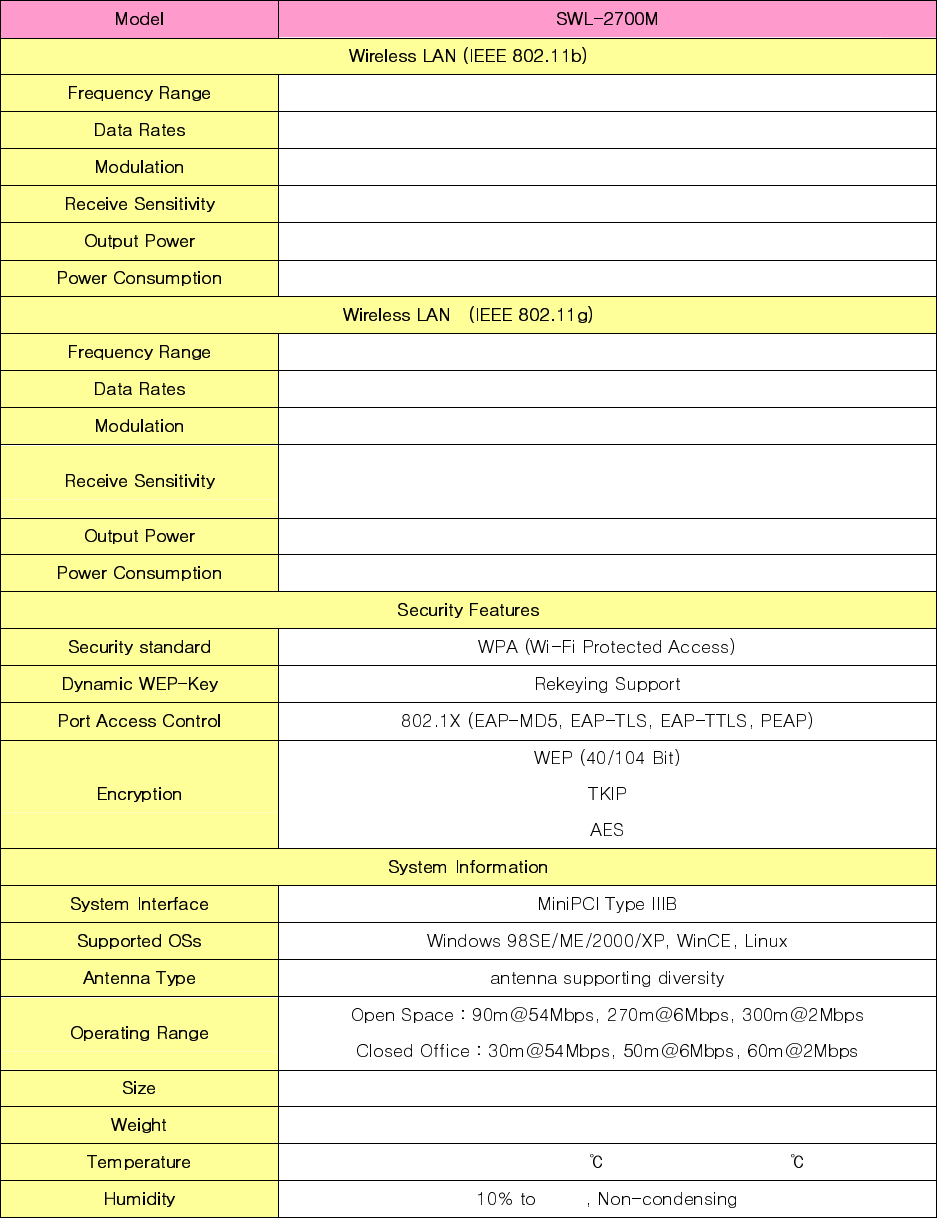
2.4 ~ 2.5 GHz (Subject to local Regulation)
1, 2, 5.5 ,11 Mbps, Full Auto
DSSS(Direct Sequence Spread Spectrum) / CCK, DBPSK, DQPSK
-87dBm(Typical) @ 11Mbps
19dBm(Typical)
Typical 450mA
2.4 ~ 2.5 GHz (Subject to local Regulation)
6, 9, 12, 18, 24, 36, 48, 54 Mbps, Full Auto
OFDM / BPSK, QPSK, 16QAM, 64QAM
-92dBm(Typical) @ 6Mbps
-72dBm(Typical) @ 54Mbps
19dBm(Typical)
480mA(Typical@transmit)
59.75x44.7x5.0mm
MAX 12g
Operating : -20~55 / Storage : -30~75
90%
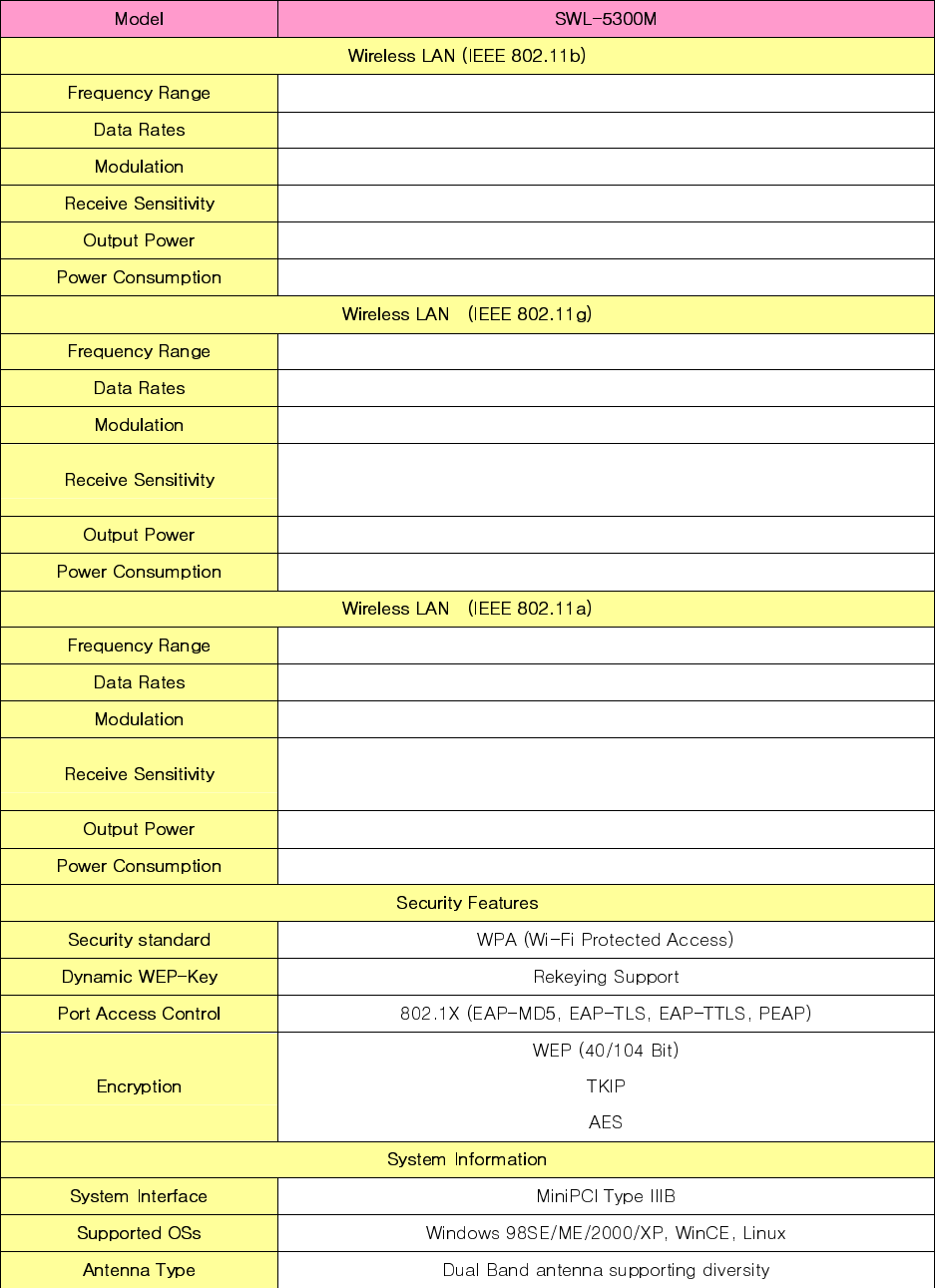
2.4 ~ 2.5 GHz (Subject to local Regulation)
1, 2, 5.5 ,11 Mbps, Full Auto
DSSS(Direct Sequence Spread Spectrum) / CCK, DBPSK, DQPSK
-87dBm(Typical) @ 11Mbps
19dBm(Typical)
Typical 450mA
2.4 ~ 2.5 GHz (Subject to local Regulation)
6, 9, 12, 18, 24, 36, 48, 54 Mbps, Full Auto
OFDM / BPSK, QPSK, 16QAM, 64QAM
-92dBm(Typical) @ 6Mbps
-72dBm(Typical) @ 54Mbps
17dBm(Typical)
480mA(Typical)
5.15 ~ 5.85 GHz (Subject to local Regulation)
6, 9, 12, 18, 24, 36, 48, 54 Mbps, Full Auto
OFDM / BPSK, QPSK, 16QAM, 64QAM
-92dBm(Typical) @ 6Mbps
-72dBm(Typical) @ 54Mbps
17dBm(Typical)
500mA(Typical@Transmit)
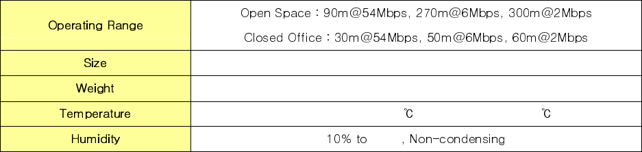
59.75x44.7x5.0mm
Max 12g
Operating : -20~55 / Storage : -30~75
90%
Appendix B – Regulatory Information
The OEM integrator has to be aware not to provide information to the end user regarding how to
install or remove this RF module in the users manual of the end product which integrate this
module.
The users manual for OEM integrators must include the following information in a prominent
location “ IMPORTANT NOTE: To comply with FCC RF exposure compliance requirements, the
antenna used for this transmitter must be installed to provide a separation distance of at least
20 cm from all persons and must not be co-located or operating in conjunction with any other
antenna or transmitter.
CAUTION: Changes or modifications not expressly approved by the manufacturer responsible
for compliance could void the user’s authority to operate the equipment
WARNING
This device complies with part 15 of the FCC Rules. Operation is subject to the following two
conditions: (1) This device may not cause harmful interference, and (2) this device must accept
any interference received, including interference that may cause undesired operation.:
INFORMATION TO USER:
This equipment has been tested and found to comply with the limit of a Class B digital device,
pursuant to Part 15 of the FCC Rules. These limits are designed to provide reasonable
protection against harmful interference in a residential installation. This equipment generates,
uses and can radiate radio frequency energy and, if not installed and used in accordance with
the instructions, may cause harmful interference to radio communications. However, there is no
guarantee that interference will not occur in a particular installation; if this equipment does
cause harmful interference to radio or television reception, which can be determined by turning
the equipment off and on, the user is encouraged to try to correct the interference by one or
more of the following measures:
1. Reorient / Relocate the receiving antenna.
2. Increase the separation between the equipment and receiver.
3. Connect the equipment into an outlet on a circuit difference from that to which the receiver is
connected.
4. Consult the dealer or an experienced radio/TV technician for help