Samsung Electronics Co GXMC990CL AWG (Advanced Wireless Gateway) User Manual Manual
Samsung Electronics Co Ltd AWG (Advanced Wireless Gateway) Manual
Manual
Samsung
Advanced Wireless Gateway
User Guide
TABLE OF CONTENTS
SAFETY INSTRUCTIONS .................................................................................................................................................................. 5
FCC Compliance ............................................................................................................................................................................... 5
UL Compliance ................................................................................................................................................................................. 6
INTRODUCTION ............................................................................................................................................................................... 6
Purpose .................................................................................................................................................................................... 6
Document Content and Organization ............................................................................................................................... 7
Conventions ............................................................................................................................................................................. 7
Chapter 1. Advanced Wireless Gateway Overview ................................................................................................................. 7
1.1 Introduction ...................................................................................................................................................................... 8
1.2 Features ............................................................................................................................................................................. 8
1.3 What’s is in the box? ...................................................................................................................................................... 8
1.4 Front Panel ........................................................................................................................................................................ 9
1.5 Back Panel ...................................................................................................................................................................... 11
1.6 Bottom panel ................................................................................................................................................................ 11
1.7 Gateway for the Installation ...................................................................................................................................... 12
Chapter 2. Installing the Advanced Wireless Gateway ....................................................................................................... 13
2.1 Introduction ................................................................................................................................................................... 13
2.2 Connect the Wireless Gateway ................................................................................................................................ 13
2.3 Connect your wireless Note PC ................................................................................................................................ 14
2.3.1 How to connect your wireless Note PC...................................................................................................... 14
CHAPTER 3. Basic Gateway Configuration.............................................................................................................................. 17
3.1 Introduction ................................................................................................................................................................... 17
3.2 Using Web UI ............................................................................................................................................................ 17
3.2.1 Web UI Connection ................................................................................................................................... 17
3.2.2 Wireless Gateway Main Window. ............................................................................................................... 18
3.2.3 Managing Operator Account ........................................................................................................................ 18
3.2.4 Managing the Gateway for the Wireless Network .................................................................................. 18
CHAPTER 4. Gateway LED Status .............................................................................................................................................. 22
4.1 Introduction ................................................................................................................................................................... 22
CHAPTER 5. Advanced Gateway Setup ................................................................................................................................... 24
5.1 Introduction ................................................................................................................................................................... 24
5.2 Parental control ............................................................................................................................................................ 24
5.3 Port Forwarding (virtual server) ............................................................................................................................... 25
5.4 port triggering ............................................................................................................................................................... 26
5.5 DMZ host ........................................................................................................................................................................ 27
CHAPTER 6. Troubleshooting the Gateway ............................................................................................................................ 28
6.1 Introduction ................................................................................................................................................................... 28
6.2 Configuration TCP/IPv4 on Windows system (XP) ................................................................................................ 28
6.2 Reset/Restore the Gateway via the RESET button in Rear Panel ..................................................................... 29

. The basic settings are provided by the manufacturer and service provider.
. The manual is intended to provide a basic guide for personal settings.
Document Content and Organization
This manual consists of ten Chapters, which are summarized as follow:
Chapter 1. This chapter describes the contents in the package and system requirements. It also
provides an overview of the gateway’s front, rear, and bottom panels.
Chapter 2. This chapter describes how to install the gateway.
Chapter 3. This chapter describes how to configure the gateway.
Chapter 4. This chapter describes how to understand the LEDs.
Chapter 5 – This chapter describes how to configure the gateway for advanced users.
Chapter 6 – This chapter provides troubleshooting information you can use in the unlikely event you
encounter a problem with the gateway.
Conventions
The following paragraph contains special information that must be carefully read and
thoroughly understood. Such information may or may not be enclosed in a rectangular box,
separating it from the main text, but is always preceded by an icon and/or a bold title.
Chapter 1. Advanced Wireless Gateway Overview
1.1 Introduction
This chapter provides an overview of Samsung Advanced Wireless Gateway(AWG) features,
indicators, and connectors to help you become familiar with the Advanced Wireless Gateway . This
chapter also lists the accessories and equipment that are provided with the Advanced Wireless
Gateway so you can verify that you received all of these items.
1.2 Features
This section provides a brief overview of the features of Samsung Gateway.
WAN connection features (DOCSIS 3.0/3.1)
. 5 Gbps Downstream at 5 ~ 85 MHz frequency range.
. 700+ Mbps Upstream at 5 ~ 85 MHz frequency range.
LAN connection features
. MoCA 2.0 to interconnect your local MoCA devices via your coax network in home.
. Four 10/100/1000BASE-T Ethernet ports for your local home network devices.
. Wireless access point for your local home network devices via the integrated IEEE 802.11n 2.4 GHz
and IEEE 802.11ac 5 GHz.
. Firewall deters hackers and protects the home network from unauthorized access via Router
Function.
Wi-Fi connection features
. Dual Band Concurrent in mode 802.11a/b/g /n/ac
. Wi-Fi 5GHZ ac 4x4 mode (4Tx, 4Rx) with MU-MIMO
. Wi-Fi 2.4GHZ n 3x3 mode (3Tx, 3Rx) with MIMO
Fax/Telephony connection features
. Two-line RJ-11 telephony ports for connecting to traditional telephones or fax machines
Design and Additional Function
. Elegant, compact cube type design
. LED status indicators on the front panel, providing an easy-to-understand display that indicates
the operational status
Management
. The Web UI allows you to configure your Gateway and network via your web browser.
. Allows software upgrades by your service provider via TR-069 methods or CableModem
1.3 What’s is in the box?
When you receive Samsung AWG, you should check the equipment and accessories to verify that
each item is in the box and that each item is undamaged.
Items of the box can be changed by by your service provider.
Basically, the box contains the following items:
. Advanced Wireless Gateway
. Power Code
. 35W Adpter for only Samsung Gateway
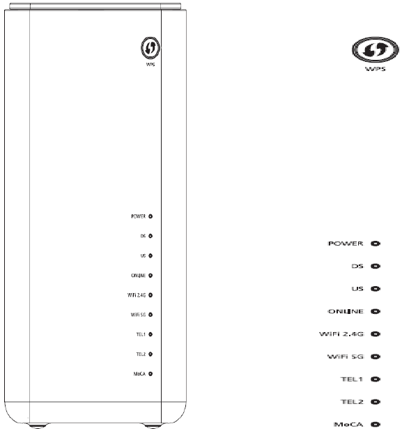
1.4 Front Panel
1. WPS (WIRELESS PROTECTED SETUP)—OFF (normal condition) Wireless Protected Setup is not
active. Blinking indicates the button has been pressed and WPS is active so that a new wireless client
can be added to the wireless network.
2. POWER—ON, power is applied to the Residential Gateway. OFF when power is off to the
Residential Gateway.
3. DS—ON, the Gateway is exchanging data with the cable network. Blinking indicates the
downstream scan is in progress.
4. US—ON, the Gateway is exchanging data with the cable network. Blinking indicates the upstream
scan is in progress.
5. ONLINE—ON, the Gateway is registered on the network and fully operational. OFF indicates the
Gateway has not registered on the network.
6. WiFi 2.4 G—ON, the wireless access point is operational. Blinking indicates that data is being
transferred over the wireless connection. OFF indicates that the wireless access point is not enabled.
7. WiFi 5 G—ON, the wireless access point is operational. Blinking indicates that data is being
transferred over the wireless connection. OFF indicates that the wireless access point is not enabled.
8. TEL1—ON indicates telephony service is enabled. Blinks when line 1 is in use. OFF indicates that
phone service for TEL 1 is not enabled.
9. TEL2—ON indicates telephony service is enabled. Blinks when line 2 is in use. OFF indicates that
phone service for TEL 2 is not enabled.
10. MoCA— ON, MoCA is operational. Blinking indicates that data is being transferred over the
MoCA connection. OFF indicates that the MoCA is not enabled.
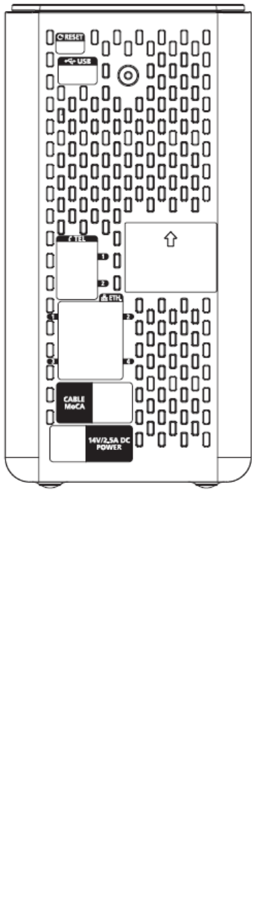
1.5 Back Panel
1. RESET—A momentary pressing (1-2 seconds) of this switch restarts the device. To press this switch,
insert a thin object, such as a paper clip, into the RESET port; then press and hold the switch for
more than ten seconds to reset all settings to their factory-settings and then restart the device.
2. USB —Connects the Residential Gateway to selected devices. For models that support USB, the
default is one USB port.
3. TEL1 and TEL2—RJ-11 telephone ports for connecting telephones, fax machines, and/or an analog
home alarm system.
4. ETHERNET—Four RJ-45 Ethernet ports allow connection to the Ethernet port on your PC or
network device.
5. CABLE/MoCA—F-connector connects to your home coax network to provide Cable and MoCA
service.
6. POWER—Connects the Gateway to the Samsung only Adpter with 35W.
1.6 Bottom panel
Product label (item A)
The label on the bottom of the Gateway contains information about your Gateway, like:
Device information
Wireless security settings
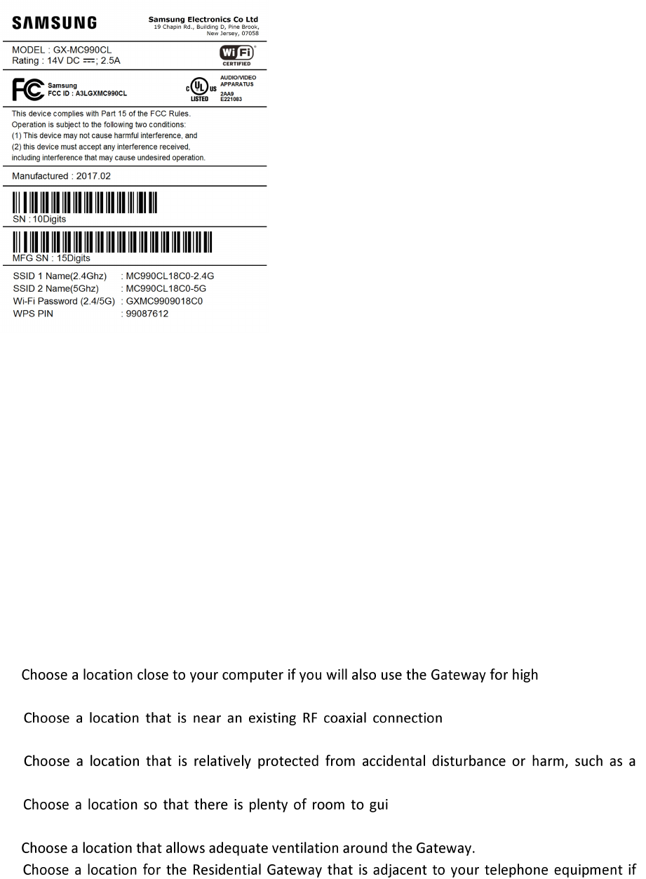
SSID 1 NAME(2.4Ghz) is the network name of the 2.4 GHz access point and is of the following format:
MC990CLXXXX-2.4G (where X is an alphanumeric character).
SSID 2 NAME(5Ghz) is the network name for the 5 GHz access point and is of the following format:
MC990CLXXXX-5G (where X is an alphanumeric character).
Wi-Fi Password(2.4/5G) is the WPA2-PSK password for the 2.4/5 GHz access point and is of the
following format: GXMC990XXXXXX (where X is an alphanumeric character).
1.7 Gateway for the Installation
The ideal location for your Gateway is where it has access to adpter and other devices. Think about
the layout of your home or office, and consult with your service provider to select the best location
for your Gateway. Read this user guide thoroughly before you decide where to place your Gateway.
Consider these recommendations:
-speed Internet
service.
to eliminate the need for an
additional RF coaxial outlet.
closet, basement, or other protected area.
de the cables away from the Gateway
without straining or crimping them.
you plan on connecting your phone directly to the Gateway.
Chapter 2. Installing the Advanced Wireless Gateway
2.1 Introduction
This chapter provides how to properly install the Advanced Wireless Gateway to your service
provider’s network and to connect the Advanced Wireless Gateway to your PC and your other IT
devices.
2.2 Connect the Wireless Gateway
Connecting Coax Cable to your cable splitter and the Gateway
1. Choose an appropriate and safe location to install the Gateway.
2. Power off your PC and other IT device.
3. Connect the active RF coaxial cable from your service provider to the coax connector labeled
CABLE/MoCA on the back of the Wireless Gateway.
4. If your Wireless Gateway supports telephone service , connect one end of a telephone jumper
cable to a telephone outlet in your home. Then connect the other end of the jumper cable to the
appropriate RJ-11 TEL1 or TEL2 port on the back of the Wireless Gateway.
5. Connect your PC to the Wireless Gateway using the Ethernet Connection or the Wireless
Connection.
6. Connect the DC jack end of the Adapter into the DC plug on the back of the Gateway.
Connect the power code to adpter and an electrical outlet.
The Wireless Gateway will perform an automatic search to locate and sign on to the broadband data
network. This process may take up to 2-5 minutes. The Wireless Gateway will be ready for use when
the Power, DS,US, and Online LEDs on the front panel of the Wireless Gateway stop blinking and
remain on continuously.
7 . If your wireless devices uses wireless networking, the WiFi 2.4 G or WiFi 5 GHz LED on the
Wireless Gateway should be on or blinking.
8 Finally, the installation is complete, and you can begin surfing the Internet sites.
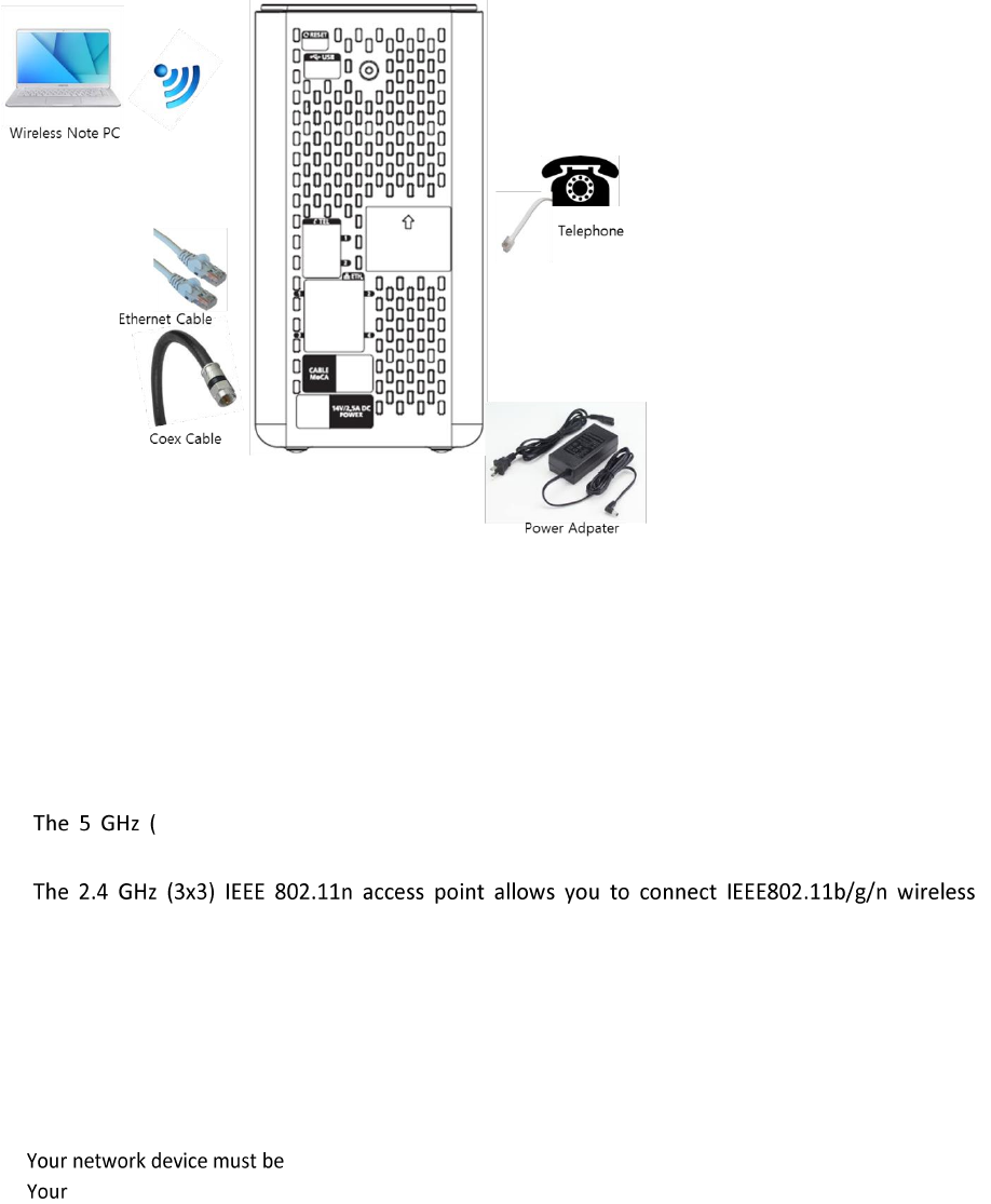
An example of connection diagram is shown in the below figure.
2.3 Connect your wireless Note PC
The Gateway has two access points that allows you to connect wireless devices to your home
network:
4x4) IEEE 802.11ac access point offers superior transfer rates, is less sensitive to
interference and allows you to connect IEEE802.11a/n/ac wireless clients.
clients. Use this access point for wireless clients that don’t support 5 GHz.
2.3.1 How to connect your wireless Note PC
Requirements
equipped with a wireless client.
network device must be configured to obtain an IP address automatically. This is the default setting.
Procedure
If you want to connect a computer using the wireless network, configure the wireless client on your computer
with the wireless
settings printed on the Gateway's side or back panel label.
For the network name, two values are available:
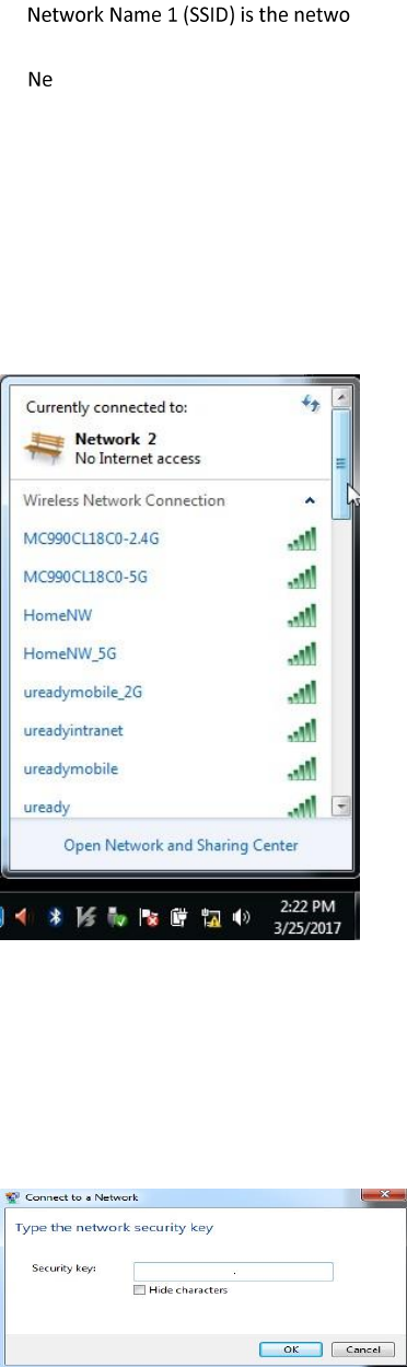
rk name of the 5 GHz access point and is of the following format:
MC990CLXXXX-2.4G (where X is an alphanumeric character).
twork Name 2 (SSID) is the network name for the 5 GHz access point and is of the following format:
MC990CLXXXX-5G (where X is an alphanumeric character).
The password is common for both access points.
To configure these settings on Windows 7.
Proceed as follows:
1 Click the wireless network icon in the notification area.
2 A list of available wireless networks appears.
Double-click the Gateway access point.
The Gateway is listed with the MC990CLXXXX-2.4G and MC990CLXXXX-5G which is printed on the Gateway's
bottom side.
3 Windows prompts you to enter the security key.
Type the Password which is printed on the Gateway's bottom panel label in the Security key and click OK.
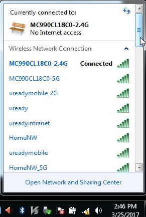
4. And then, the wireless Note PC is connected to the Gateway
CHAPTER 3. Basic Gateway Configuration
3.1 Introduction
In this chapter, the basic gateway configuration using web and how to use Web UI is described.
3.2 Using Web UI
3.2.1 Web UI Connection
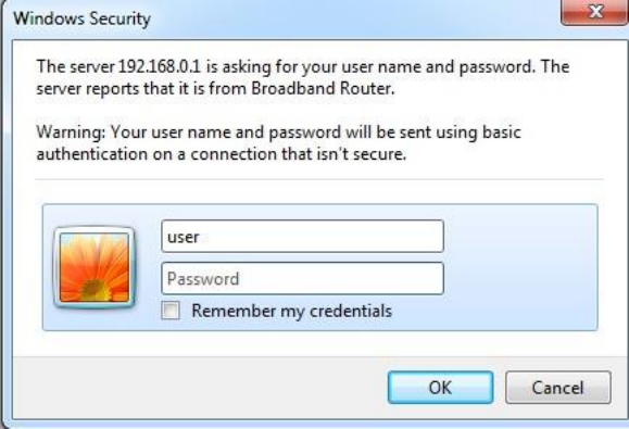
1. Open your web browser and browse to http://192.168.0.1, using a computer or device that is
currently connected to you Gateway (either wired or wirelessly).
2. The Gateway prompts you to enter the username and password. Enter your user name
(default: admin) and password (default:admin) and click OK.
Input the password of the Gateway that you got from your system default.
(Default ID and Passwd : admin/admin, support/support, user/user)
3.2.2 Wireless Gateway Main Window.
The Gateway Main window consists of menu bar, sub-menus, and detail windows of each
menu.
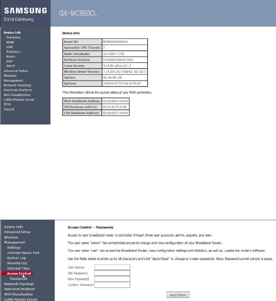
3.2.3 Managing Operator Account
After the first login, you go through the course of changing the password via Access Control Menu.
Configuration using Web UI
In the menu of <Management >, select <Aceess Control > and then select the
<Passwords> menu in the sub-menus.
When you enter ID/PW values and click the <Apply/Save> button, the
configuration is applied.
3.2.4 Managing the Gateway for the Wireless Network
The Gateway supports 2 primary wireless network (2.4G/5G) and 6 multiple guest networks in
each one primary wireless network.
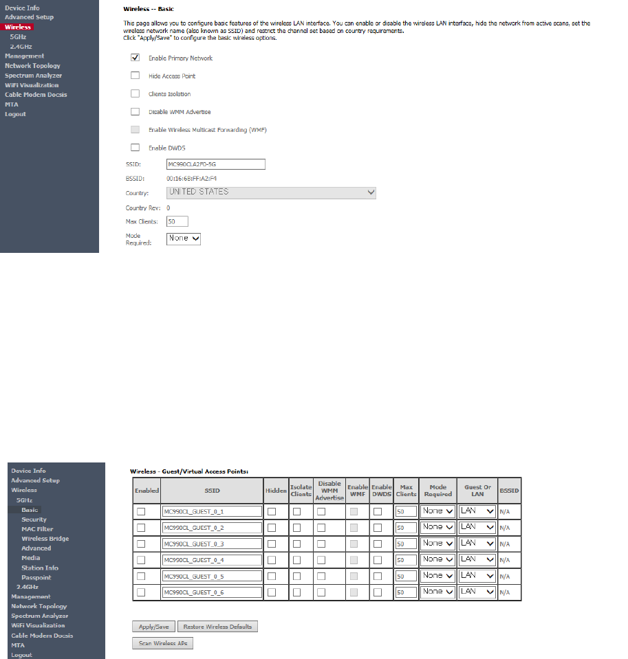
Configuration Primary Wireless Network
1. In the menu of <Wireless>, select Primary Wireless Network (<5GHz-Basic> or <2.4GHz-Basic>)
to configure.
2. Check/Uncheck “Enable Primary Network” check box to turn ON or OFF primary wireless network.
3. Check “Hide Access Point” check box to block broadcasting and hide primary wireless network.
4. Enter new SSID to change primary wireless network’s name in SSID field.
-. 32 characters maximum (letters, numbers and/or special characters)
5. Click <Apply/Save> button to apply and save the changed configuration.
Configuration Guest Wireless Network
1. To enable guest network, check “Enabled” check boxes.
2. Enter new SSID to change guest wireless network’s name in SSID field.
-. 32 characters maximum (letters, numbers and/or special characters)
3. Check “Hidden” check box to block broadcasting and hide guest wireless network.
5. Click <Apply/Save> button to apply and save the changed configuration.
Configuration Wireless Network Security – Manual Setup AP
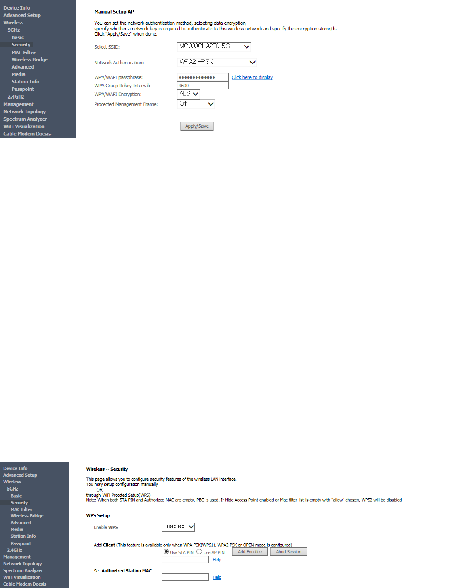
1. In the menu of <Wireless>, select Security Menu (<5GHz-Security> or <2.4GHz-Security>) to
configure wireless networks’ security settings.
2. Select one of the following Network Authentication:
A. Open : allows access to the wireless network without security key.
B. WPA2 : uses an authentication server to generate keys or certificates.
C. WPA2-PSK : use Pre-Shared key(PSK) for encryption.
D. Mixed WPA2/WPA : combination Wi-Fi Protected Access version 2 and Wi-Fi Protected
Access with using an authentication server to generate keys or certificates.
E. Mixed WPA2/WPA-PSK : combination Wi-Fi Protected Access version 2 with Pre-Shared Key
and Wi-Fi Protected Access with Pre-Shared Key.
3. WPA/WAPI passphrase : Enter wireless network’s password.
4. WPA/WAPI Encryption :
A. AES (Advanced Encryption Standard) : enhanced encryption type to WPA2 over WPA.
B. TKIP+AES(Temporal Key Integrity Protocol and Advanced Encryption Standard) : TKIP and
AES encryption types are capable to access wireless network.
5. Protected Management Frame : Select “Capable or Required” to protect management frames
such as authentication, de-authentication, association, dissociation.
6. Click <Apply/Save> button to apply and save the changed configuration.
Configuration Wireless Network Security – WPS (WiFi Protected Setup) Setup
1. In the menu of <Wireless>, select Security Menu (<5GHz-Security> or <2.4GHz-Security>) to
configure wireless networks’ WPS setup.
2. Select “Enabled” to Enable WPS.
A. For WPS-PIN configuration, choose “Use STA PIN” radio button and enter Client’s PIN
number. Press “Add Enrollee” button and start Client’s WPS PIN.
B. For WPS-PBC configuration, choose “Use STA PIN” radio button and empty both STA PIN
and Authorized MAC. Press “Add Enrollee” button and start Client’s WPS PBC.
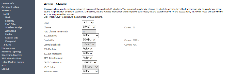
Configuration Wireless Network Channel/Bandwidth
1. In the menu of <Wireless>, select Advanced Menu (<5GHz-Advanced> or <2.4GHz-Advanced>)
to configure wireless networks’ radio configuration.
2. Select “Channel” and “Bandwidth” to improve wireless network interference and throughput
performance.

CHAPTER 4. Gateway LED Status
4.1 Introduction
This chapter provides LED’s status of front panel when the Advanced Wireless Gateway is power on,
provisioning, normal status, and abnormal status.
Gateway LED indicates the various statuses of system. Each LED displays the following
information:
POWER LED status is below table
POWER
LED State
Description
ON
The Gateway is power on when the DC input supplied
OFF
The Gateway is power off when the DC input don’t
supplied
CableMode start up LED sequence is table below.
CableModem
LED
Status
Description
DS
ON
Downstream looking is in completed
Blinking
Downstream looking is in progress
OFF
The Gateway is power off
US
ON
Upstream looking is in completed
Blinking
Downstream looking is in progress
OFF
The Gateway is power off
ONLINE
ON
Downstream and Upstream looking
are completed
The connection is completed on
internet
Blinking
Downstream and Upstream looking
are in progress
OFF
The Gateway is power off
Wi-Fi connection LED sequence is table below.
Wi-Fi
LED
Status
Description
WiFi 2.4G
ON
The Wi-Fi 2.4Ghz service is enabled
Blinking
The data is being transferred in
2.4Ghz over the wireless connection
OFF
The 2.4Ghz Wi-Fi service is disabled
WiFi 5G
ON
The Wi-Fi 5Ghz service is enabled
Blinking
The data is being transferred in 5Ghz

over the wireless connection
OFF
The 5Ghz Wi-Fi service is disabled
Telephony and MoCA connection LED sequence are table below.
LED
Status
Description
Telephony
TEL1/TEL2
ON
The telephone or fax is not in use
(on-hook)
Blinking
The telephone or fax is in use
(off-hook)
OFF
The telephony service is disabled
MoCA
MoCA
ON
The MoCA service is enabled
Blinking
The MoCA network has traffice
OFF
The MoCA service is disabled
Ethernet connection LED sequence of rear panel are table below.
LED
Status
Description
Ethernet
Orange
Blinking
Blinking while data exchanging
OFF
No data exchanging
Green
ON
Link connection display
OFF
No link connection
CHAPTER 5. Advanced Gateway Setup
5.1 Introduction
This chapter describes the setup procedures for the security related setting such as parental control
And port control for IP application. It includes blocking or open function, remote access, firewall
function, and more
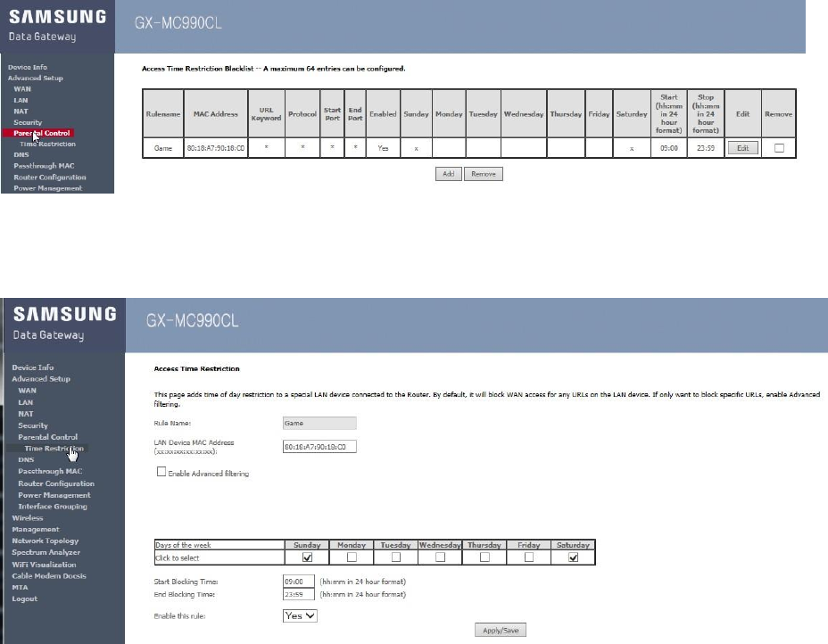
5.2 Parental control
Keep your children safe online with the parental control rules for Gateway
A max rules number is 64 entries.
The configuration windows is shown below. Click <Add> button for input values.
Configuration using Web UI
In the menu <Advanced Setup>, select <Parental Control >, select
<Time Restriction > and then select the <Add> button .
Click Apply/Save after input Rule Name, MAC Address, days, and times, then user can configure
the restricted service status.
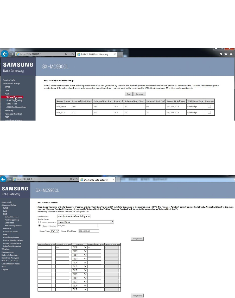
5.3 Port Forwarding (virtual server)
Port forwarding opens certain ports on your home or small business network, usually blocked from
access by your router, to the Internet. Opening specific ports can allow games, NAS servers,
BitTorrent clients, and other applications to work through the usual security of your router that
otherwise does not permit connections to these ports.
The port Forwarding has 32 entries.
Configuration using Web UI
In the menu of <Advanced Setup >, select <NAT > and then select the
<Virtual Servers> menu in the sub-menus.
When you click the <Add> button in the Virtual Servers window, the servers creation window
is displayed. When you enter a configuration value and click the <Apply/Save> button, the
configuration is applied.
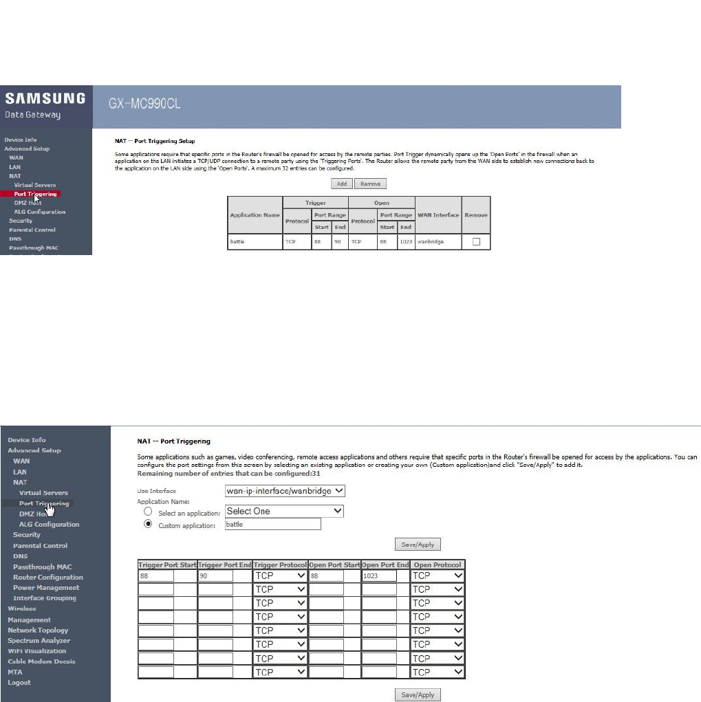
5.4 port triggering
The Port Triggering is an advanced feature that can be used for gaming and other internet
applications.
The Port Triggering setup window is displayed as below.
Configuration using Web UI
In the menu of <Advanced Setup >, select <NAT > and then select the
<Port Triggering> menu in the sub-menus.
When you click the <Add> button in the Port Triggering window, the triggering creation window
is displayed. When you enter a configuration value and click the <Apply/Save> button, the
configuration is applied.
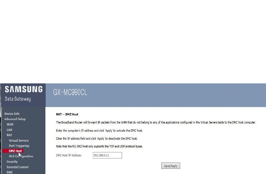
5.5 DMZ host
A DMZ (demilitarized zone) on a gateway refers to a DMZ Host. A gateway DMZ host is a host on the
internal network that has all UDP and TCP ports open and exposed, except those ports otherwise
forwarded. They are often used a simple method to forward all ports to another firewall/NAT device.
Configuration using Web UI
In the menu of <Advanced Setup >, select <NAT > and then select the
<DMZ Host> menu in the sub-menus.
When you enter a configuration IP value and click the <Apply/Save> button, the
configuration is applied.
CHAPTER 6. Troubleshooting the Gateway
6.1 Introduction
In this chapter, troubleshooting method are described.
.
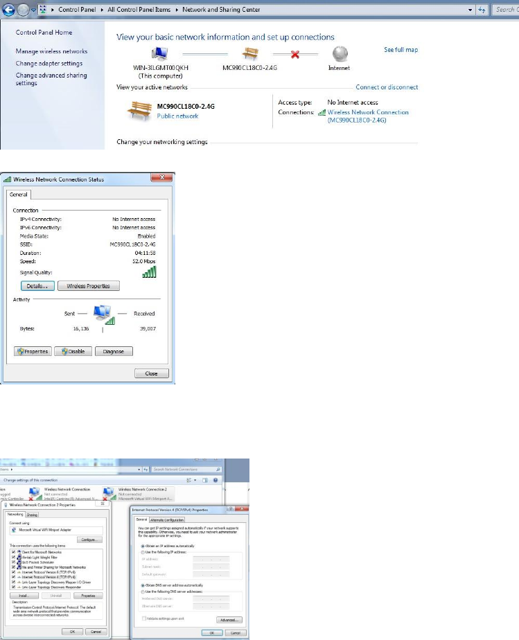
6.2 Configuration TCP/IPv4 on Windows system (XP)
1. Open Network Connections by clicking the Start button, and then clicking Control Panel.
2. Selecting Network and Sharing Center, click View network connections as below.
3. Selecting the connection , you can see status as below.
4. Selecting the Properties , you can see networking protocol and then
click Internet Protocol Version 4 (TCP/IPv4)
6.2 Reset/Restore the Gateway via the RESET button in Rear
Panel
To reset the Gateway to factory defaults, you should press and hole the RESET button on the rear
panel of Gateway for more five or seconds. You can also need to do this if a misconfigurations ha
locaked out all access.
1 Make sure that the Gateway is turned on.
2 If you want to:
Reset the Gateway, use a pen or an unfolded paperclip to push the recessed Reset button on the
back panel of the Gateway for approximately 5 seconds and then release it.
Restore the factory default settings of the Gateway, use a pen or an unfolded paperclip to push the
recessed Reset button on the back panel of the Gateway for at least 15 seconds and then release it.
3 The Gateway can restart.

FCC Information
This device complies with part 15 of the FCC Results. Operation is subject to the
following two conditions :
(1) This Device may not cause harmful interface, and
(2) This device must accept any interference received, including interference that
may cause undesired operation.
Note: This equipment has been tested and found to comply with the limits for CLASS B digital device,
pursuant to Part 15 of FCC Rules. These limits are designed to provide reasonable protection against harmful
interference when the equipment is operated in a commercial environment This equipment generates, uses
and can radiate radio frequency energy and, if not installed and used in accordance with the instructions,
may cause harmful interference to radio communications. However, there is no guarantee that interference
will not occur in a particular installation. If this equipment does cause harmful interference to radio or
television reception, which can be determined by turning the equipment off and on, the user is encouraged
to try correct the interference by one or more of the following measures:
1.1. Reorient or relocate the receiving antenna.
1.2. Increase the separation between the equipment and receiver.
1.3. Connect the equipment into an outlet on a circuit different from that to which receiver is connected.
1.4. Consult the dealer or experienced radio/TV technician for help.
WARNING
Changes or modifications not expressly approved by the manufacturer could void the
user’s authority to operate the equipment.
“CAUTION : Exposure to Radio Frequency Radiation.
Antenna shall be mounted in such a manner to minimize the potential for human contact during normal
operation. The antenna should not be contacted during operation to avoid the possibility of exceeding the
FCC radio frequency exposure limit.
Information for OEM Integrator
This device is intended only for OEM integrators under the following conditions:
1) The antenna must be installed such that 20 cm is maintained between the antenna and users, and
2) The transmitter module may not be co-located with any other transmitter or antenna.
“ CAUTION: Exposure to Radio Frequency Radiation.
This equipment complies with FCC radiation exposure limits set forth for an uncontrolled environment. This
equipment should be installed and operated with minimum distance of 20cm between the radiator and your
body. This transmitter module is authorized only for use in device where the antenna may be installed such
that 20 cm may be maintained between the antenna and users.”

Samsung
Advanced Wireless Gateway
User Guide
© 2017 Samsung Electronics Co., Ltd.
All rights reserved.
Information in this manual is subject to change without
notice.