Samsung Electronics Co IWB-P1 Zigbee Touch User Manual PDP Display
Samsung Electronics Co Ltd Zigbee Touch PDP Display
UserManual.wiki
>
Samsung Electronics Co
>
IWB P1 User Manual
users manual
Navigation menu
Upload a User Manual
Namespaces
Wiki Guide
HTML
PDF
Info
Views
User Manual
Discussion / Help
Navigation
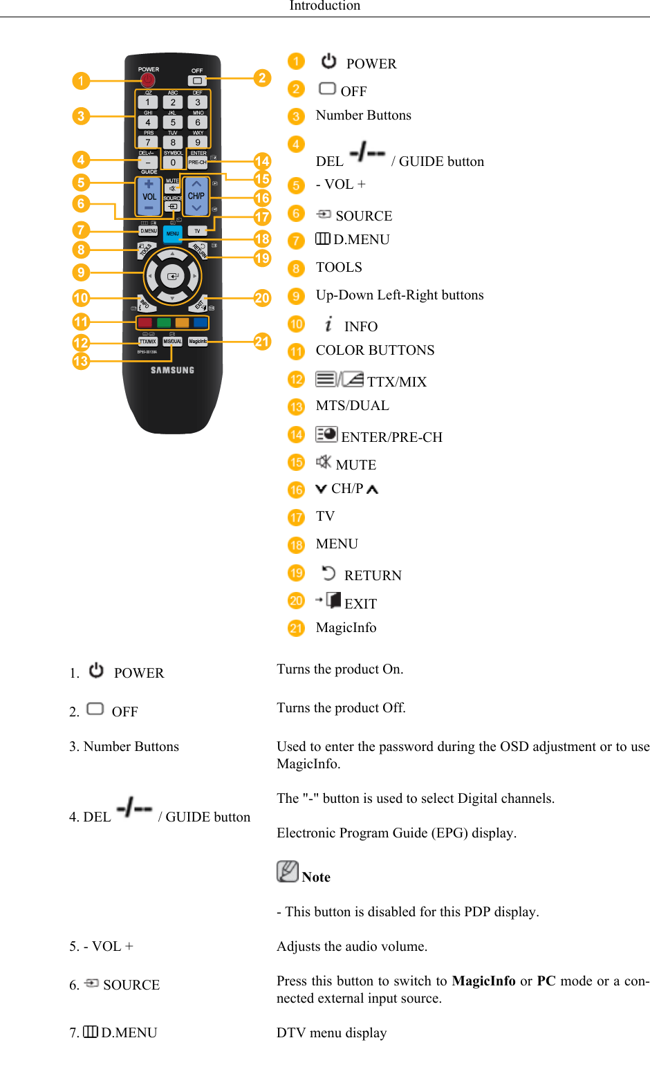
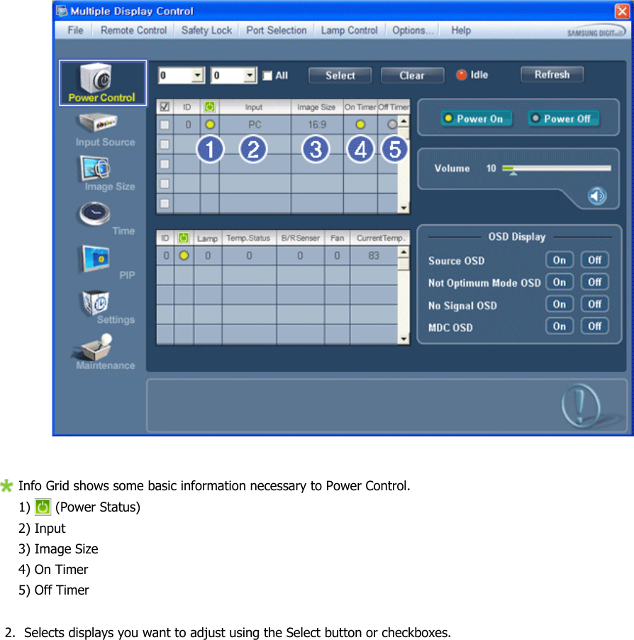
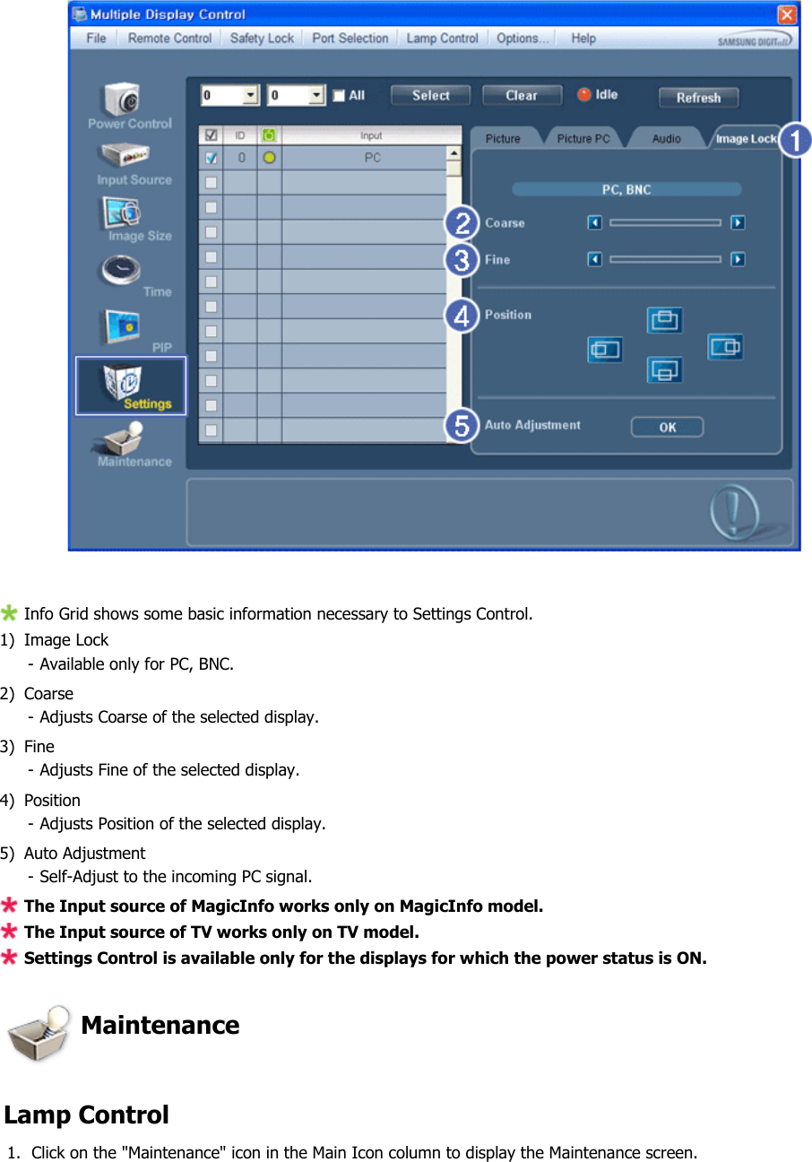
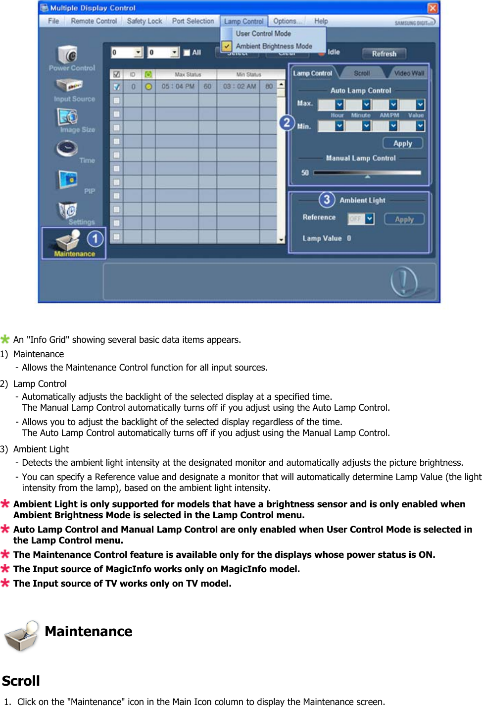
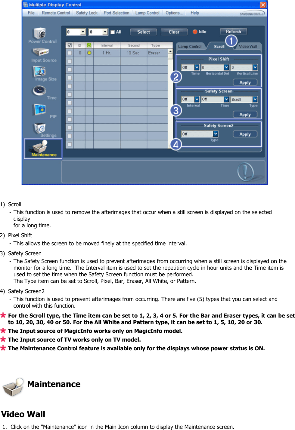
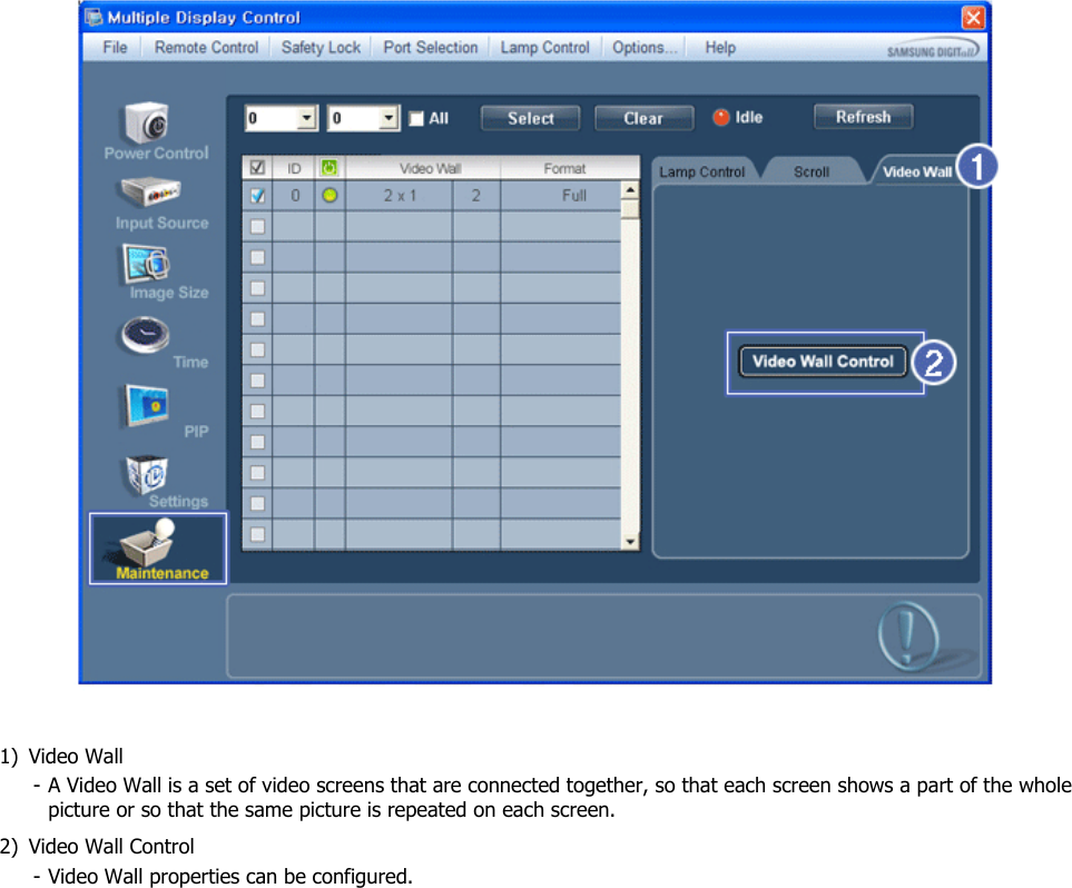
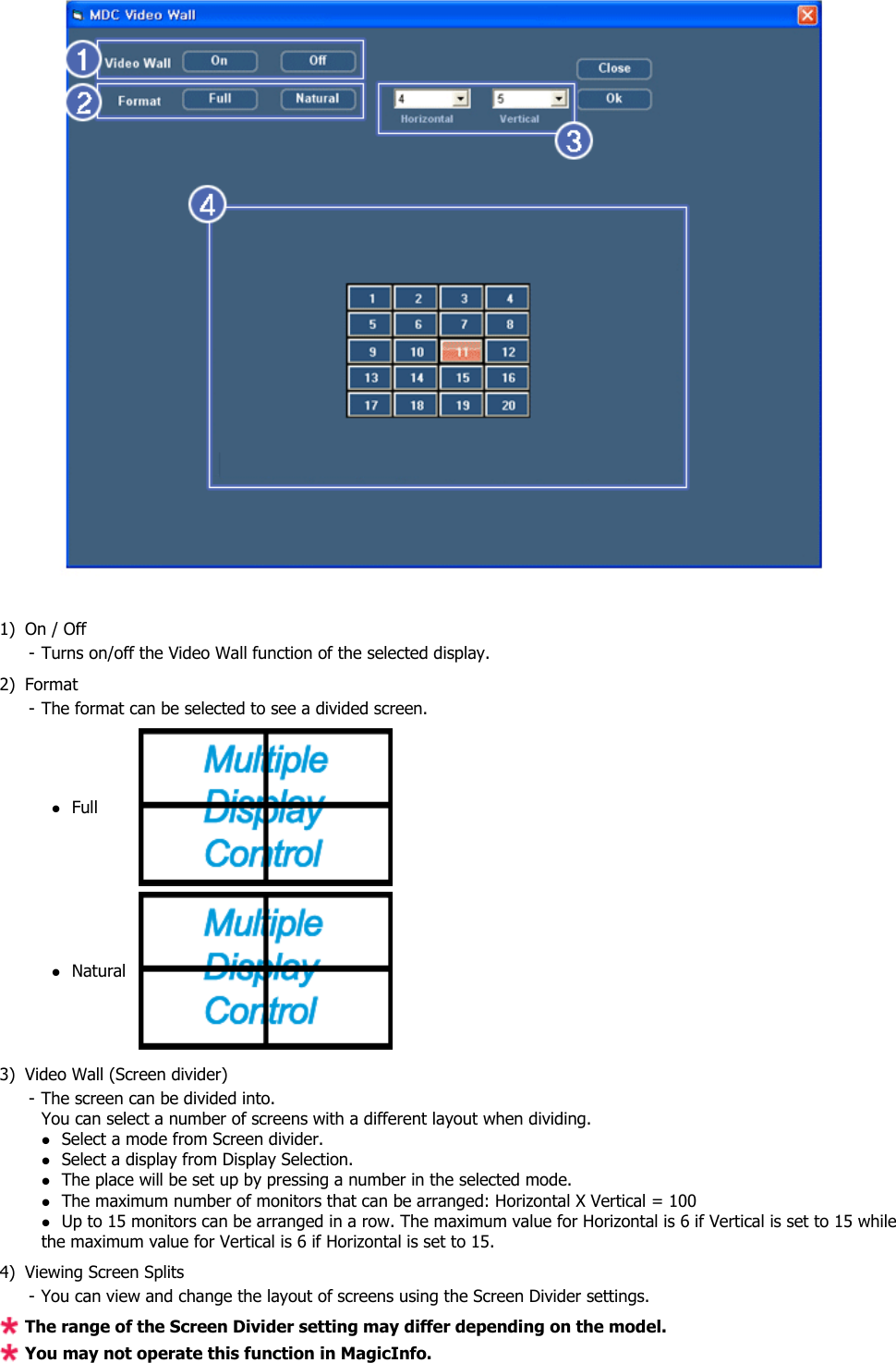
![FrontSOURCE button [SOURCE]Switches from PC mode to Video mode. Changing the source is only allowed forexternal devices that are connected to the PDP Display at the time.[PC] → [DVI] → [AV] → [HDMI] → [MagicInfo] → [Component] →[BNC]Enter button [ ]Activates a highlighted menu item. Note• This product is not compatible with MagicInfo.MENU button [MENU]Opens the on-screen menu and exits from the menu. Also use to exit the OSD menuor return to the previous menu.- VOL+Moves from one menu item to another horizontally or adjusts selected menu val-ues. When OSD is not on the screen, push the button to adjust volume. SEL Moves from one menu item to another vertically or adjusts selected menu values.Power button [ ]Use this button for turning the PDP Display on and off.Power indicatorShows PowerSaver mode by blinking green NoteSee PowerSaver described in the manual for further information regarding powersaving functions. For energy conservation, turn your PDP Display OFF when it isnot needed or when leaving it unattended for long periods.Remote Control SensorAim the remote control towards this spot on the PDP Display.Introduction](https://usermanual.wiki/Samsung-Electronics-Co/IWB-P1/User-Guide-1616926-Page-13.png)
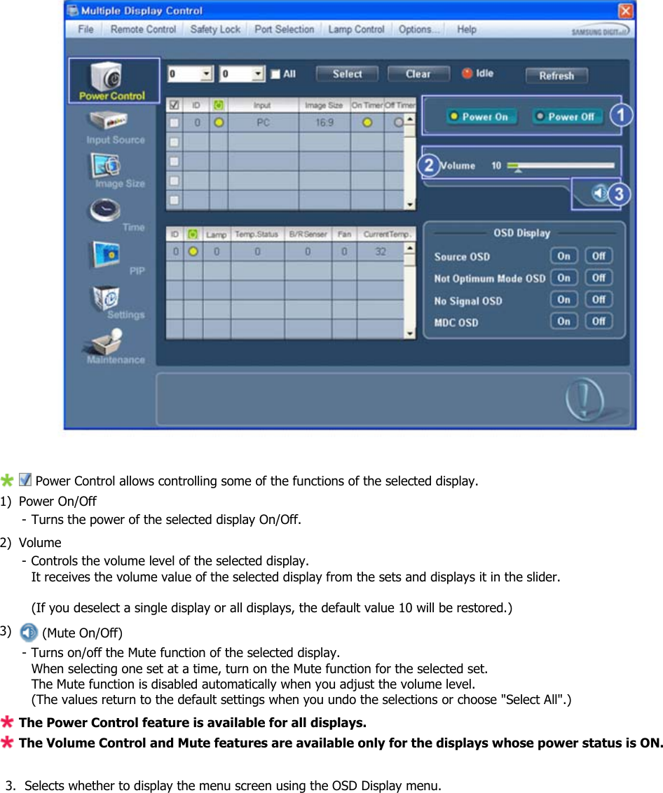
![Rear NoteFor detailed information concerning cable connections, refer to Connecting Cables under Setup. ThePDP Display's configuration at the back may vary slightly depending on the PDP Display model. POWER INThe power cord plugs into the PDP Display andthe wall plug. RS232C OUT/IN (RS232C Serial PORT)MDC(Multiple Display Control) Program PortRGB IN (PC Connection Terminal (Input))•Use a D-Sub Cable (15 pin D-Sub) - PC mode(Analog PC)• Connect the RGB IN port on the monitor tothe BNC port on the PC using the RGB toBNC cable. DVI IN (PC Video Connection Terminal)Connect the [DVI IN] port on the monitor to theDVI port on the PC using the DVI cable. Introduction](https://usermanual.wiki/Samsung-Electronics-Co/IWB-P1/User-Guide-1616926-Page-14.png)
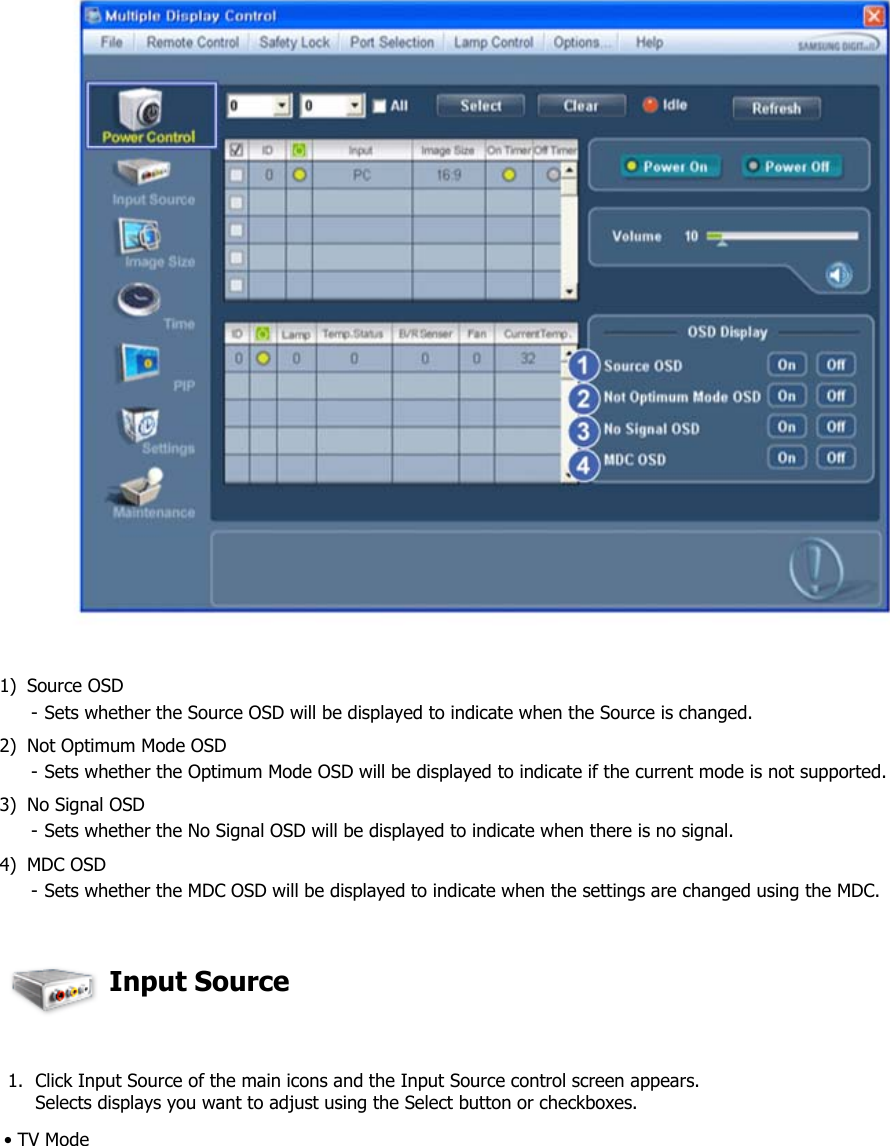
![DVI/RGB AUDIO IN(PC/DVI Audio Con-nection Terminal (Input))Connect an audio cable to [R-AUDIO-L] on themonitor and the audio out port on the source de-vice.AV/COMPONENT AUDIO IN [R-AUDIO-L]Connect an audio cable to [R-AUDIO-L] on themonitor and the audio out port on the source de-vice. DVI OUT•Connect a monitor to another monitor througha DVI cable.• Connect the [DVI OUT] port on the monitorto the [HDMI IN] port on the other monitorusing the DVI to HDMI cable.• DVI, HDMI and network signals sent via the[DVI OUT] port are displayed on the seconddisplay which has the DVI IN port. AV IN [VIDEO]Connect the [AV IN (VIDEO)] terminal of yourmonitor to the video output terminal of the exter-nal device using a VIDEO cable.AUDIO OUTHeadphone/External speaker output terminal. HDMI INConnect the HDMI terminal at the back of yourPDP Display to the HDMI terminal of your digitaloutput device using a HDMI cable.Up to HDMI cable 1.2 can be supported. Introduction](https://usermanual.wiki/Samsung-Electronics-Co/IWB-P1/User-Guide-1616926-Page-15.png)
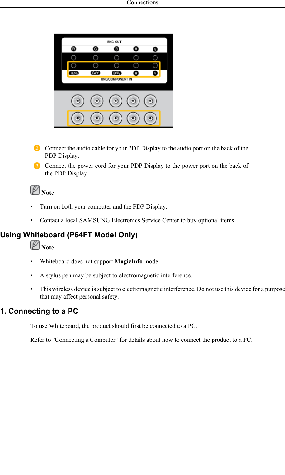
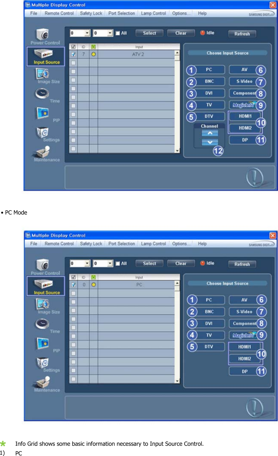
![BNC OUT [R, G, B, H, V] (BNC Terminal(Output))BNC (Analog PC) Connection: connecting the R,G, B, H, V ports.The number of PDP Displays that can be connec-ted to the loopout depends on the cables, signalsource, etc. With cables or signal source wherethere is no degradation, up to 10 PDP Displayscan be connected (May not be supported depend-ing on the connected cable). BNC/COMPONENT IN [R/PR, G/Y, B/PB, H,V] (BNC/Component Connection Terminal (in-put))- During BNC input, please check specificationsfor the input ports below.• [R/PR] --> Red port input• [G/Y] --> Green port input• [B/PB] --> Blue port input- During component input, please check specifi-cations for the input ports below.• [R/Y] --> Green port input• [G/PB] --> Blue port input• [B/PR] --> Red port input This product has an internal speaker.Remote Control NoteThe performance of the remote control may be affected by a TV or other electronic device operatingnear the PDP Display , causing a malfunction due to interference with the frequency.Introduction](https://usermanual.wiki/Samsung-Electronics-Co/IWB-P1/User-Guide-1616926-Page-16.png)
![ConnectionsConnecting a ComputerThere are several ways to connect the computer to the monitor. Choose one fromthe following options. Using the D-sub (Analog) connector on the video card.• Connect the D-sub to the 15-pin, [RGB IN] port on the back of your PDPDisplay and the 15 pin D-sub Port on the computer. Using the DVI (Digital) connector on the video card.• Connect the DVI Cable to the [DVI IN] port on the back of your PDP Displayand the DVI port on the computer.](https://usermanual.wiki/Samsung-Electronics-Co/IWB-P1/User-Guide-1616926-Page-36.png)
![Using the HDMI (digital) output on the graphics card.• Connect the [HDMI IN] port on the PDP Display to the HDMI port on the PCusing the HDMI cable. NoteWhen the HDMI cable to the PC, ensure that you select HDMI from both theSource List and Edit Name before selecting PC or DVI device so that normalPC screen and sound can be outputted. Using the BNC (Analog) connector on the video card.• Connect the [BNC/COMPONENT IN] port on the monitor to the BNC porton the PC using the BNC to BNC cable.Connections](https://usermanual.wiki/Samsung-Electronics-Co/IWB-P1/User-Guide-1616926-Page-37.png)
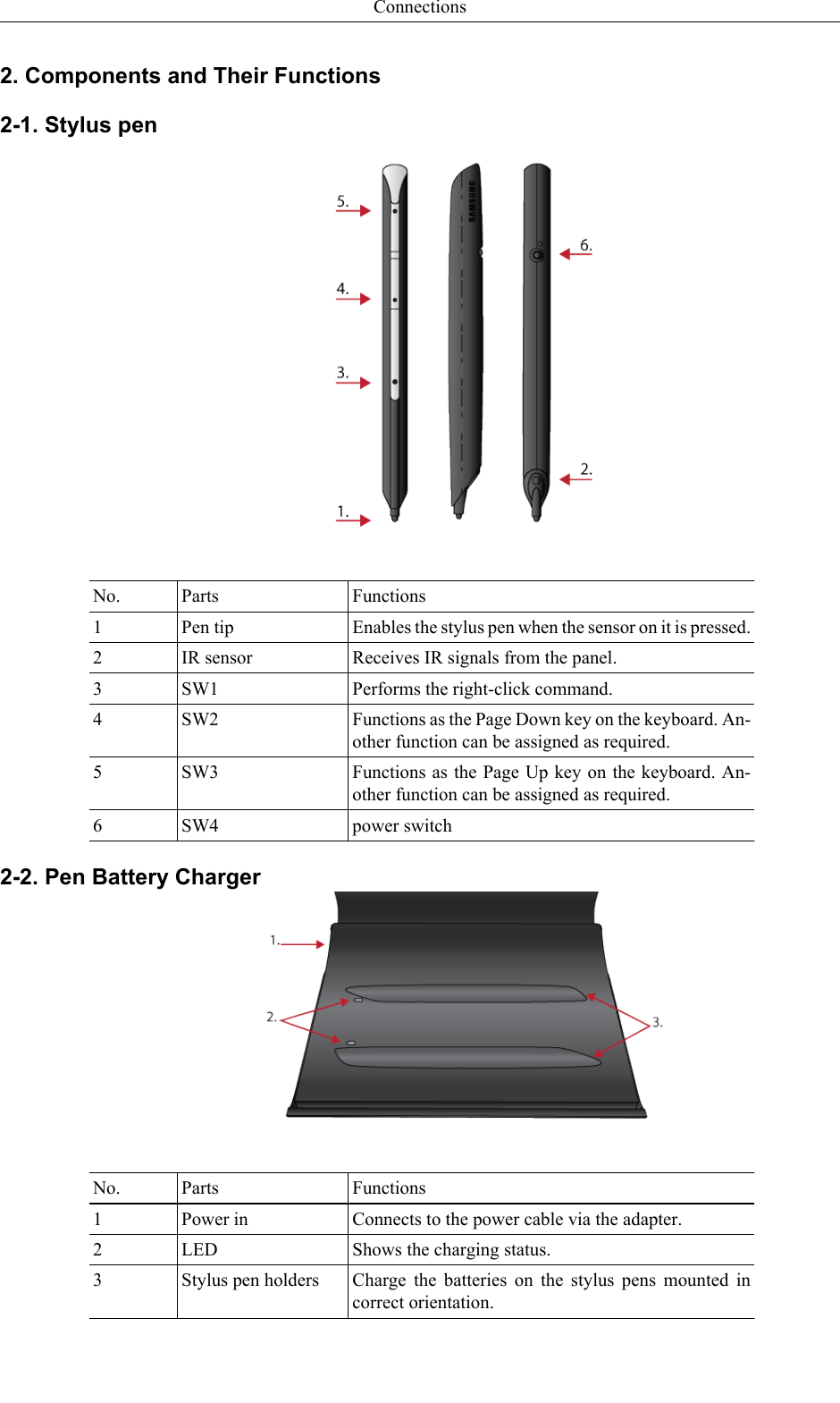
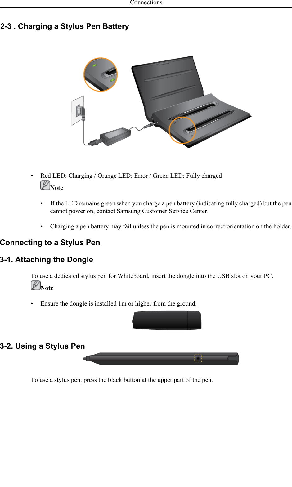
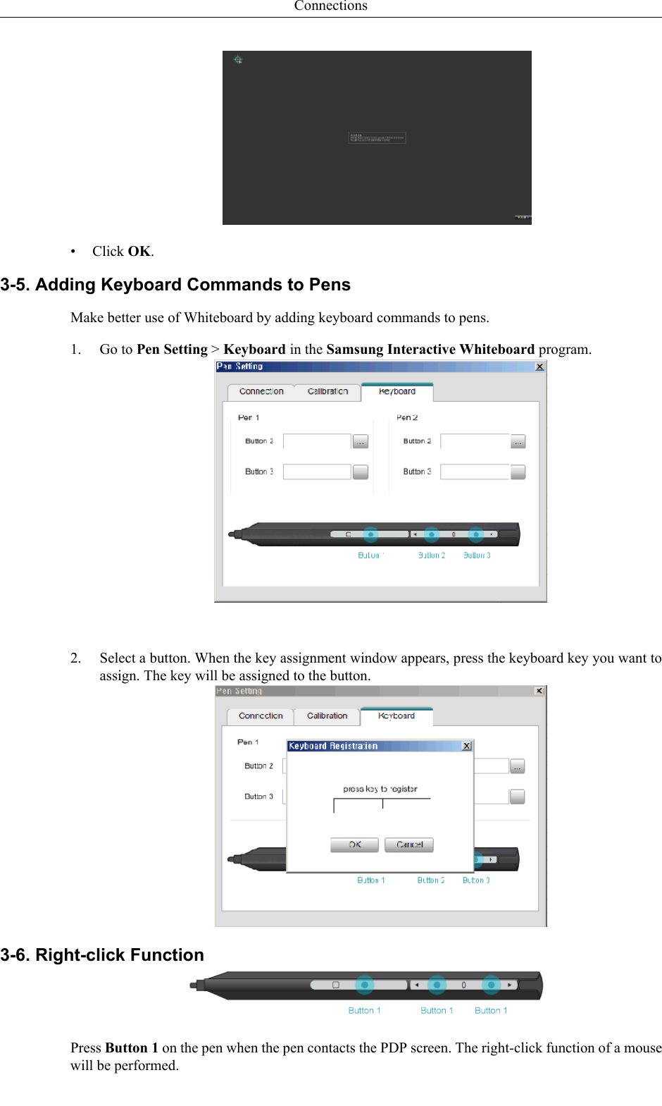
![3-3. Pairing Stylus Pens with the MonitorTo connect dual pens to the monitor, install the drawing program in the provided CD on the PC. Referto "Installing Whiteboard" for details about how to install the drawing program.• Go to Control Panel and run Samsung Interactive Whiteboard.(Alternatively, click the star icon[ ] -> Pen Setting in the bottom left corner of the drawingprogram.)• Press and hold the (black) power button on the stylus pen for 10 seconds when the power buttonis turned off.• Powering on the pen: Press the black power button once. The red LED will blink several timesand the pen will power on.• Powering off the pen: Press and hold the black power button for 3 seconds. The red LED willblink several times and the pen will power off.• Press Pairing in the Samsung Interactive Whiteboard program. If No Pairing changes toConneted, a pairing has been successfully performed and taps of the pen on the screen will im-mediately be recognized.• Pairing is required only once. After a pen is paired with the monitor, powering on the pen willenable taps of the pen on the screen to be recognized.3-4. Activating Calibration• Go to Control Panel and run Samsung Interactive Whiteboard.(Alternatively, click the star icon[ ] -> Pen Setting in the bottom left corner of the drawingprogram.)• Go to the Calibration tab.• Click Start Calibration.• Tap the four circles in sequence using the pen, following the instructions displayed.Connections](https://usermanual.wiki/Samsung-Electronics-Co/IWB-P1/User-Guide-1616926-Page-41.png)
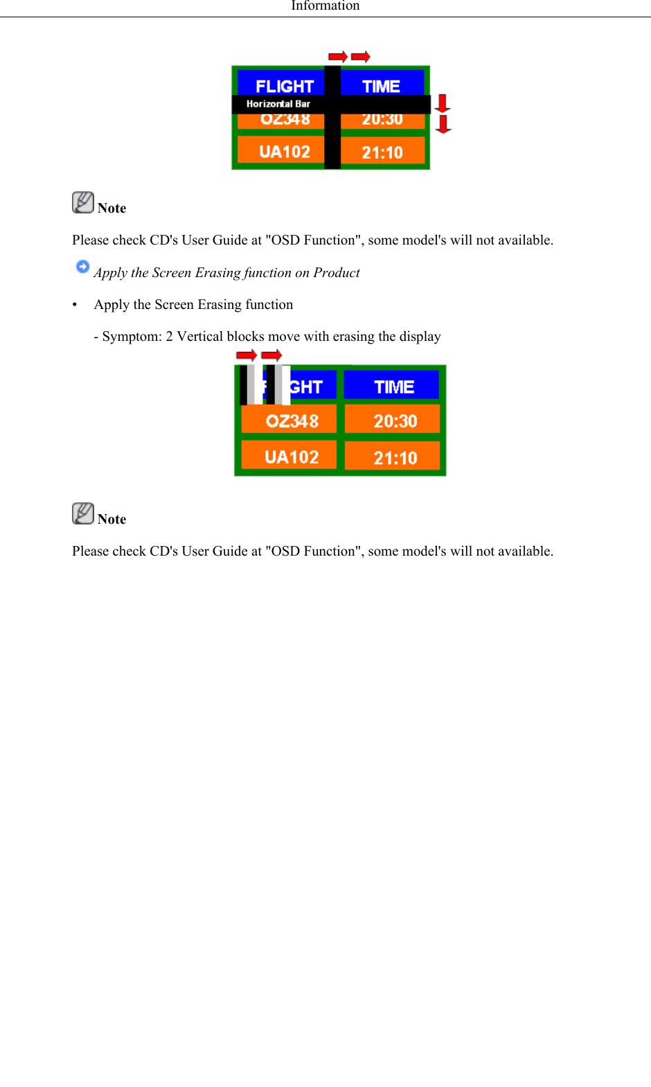
![Note• The right-click function does not work unless the pen contacts the PDP screen.4. Afterimage Burn-in PreventionNote•Afterimages can occur on this product due to the nature of PDP devices and the manufacturer shallnot be liable for this issue.• To prevent afterimages, it is recommended that you observe the following instructions when usingthe product.Instructions•Ensure the same still image is not displayed for long hours.• When you need to display the same still image for long hours, be sure to activate Screen saverat regular intervals.• It is best to activate Screen saver when the Samsung Interactive Whiteboard is not in use.• Using screen saverActivating screen saver (when the Interactive Whiteboard software is notin use)•Go to MENU -> Setup-> Safety Screen in the onscreen display menu and select Pat-tern mode. A screen saver pattern will activate.Activating screen saver (when the Interactive Whiteboard software is inuse)•Click [ ] and select Eliminate Image Retention in the Interactive Samsung InteractiveWhiteboard. A screen saver pattern will be activated.Connections](https://usermanual.wiki/Samsung-Electronics-Co/IWB-P1/User-Guide-1616926-Page-43.png)
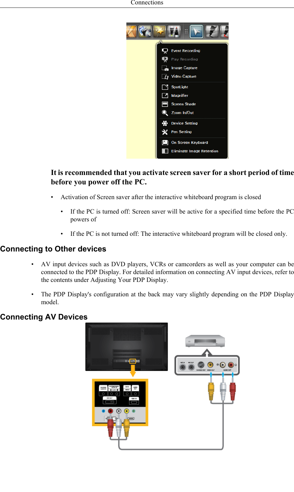
![1. Connect an audio cable to the audio output port on the external device and [AV/COMPONENTAUDIO IN[R-AUDIO-L]] port on the monitor, and connect the video output port on the externaldevice to the [AV IN [VIDEO]] port on the monitor.2. Play the DVD, VCR or Camcorder with a DVD disc or tape inserted.3. Select AV using the SOURCE button on the front of the PDP display or on the remote.Connecting to a Camcorder1. Locate the AV output jacks on the camcorder. They are usually found on the side or back of thecamcorder. Connect a set of audio cables between the AUDIO OUTPUT jacks on the camcorderand the [AV/COMPONENT AUDIO IN [R-AUDIO-L]] on the PDP Display .2. Connect a video cable between the VIDEO OUTPUT jack on the camcorder and the [AV IN[VIDEO]] on the PDP Display .3. Select AV for the Camcorder connection using the SOURCE button on the front of the PDPDisplay or on the remote control.4. Then, start the Camcorder with a tape inserted. NoteThe audio-video cables shown here are usually included with a Camcorder. (If not, check your localelectronics store.)If your camcorder is stereo, you need to connect a set of two cables.Connections](https://usermanual.wiki/Samsung-Electronics-Co/IWB-P1/User-Guide-1616926-Page-45.png)
![Connecting the BNC to BNC cable1. Connect the [BNC/COMPONENT IN [R/PR, G/Y, B/PB]] ports on the monitor to the BNC porton the external device using the BNC to BNC cable.2. Select BNC using the SOURCE button on the front of the PDP Display or on the remote control.Connecting Using a DVI Cable1. Connect between the [DVI OUT] port on the PDP Display and the input port on another monitorusing a DVI cable.2. Connect between the [AUDIO OUT] port on the PDP Display and the audio input port on anothermonitor using a stereo cable.3. Select DVI using the SOURCE button on the front of the PDP Display or on the remote control. Note[DVI OUT] does not support HDCP.Connections](https://usermanual.wiki/Samsung-Electronics-Co/IWB-P1/User-Guide-1616926-Page-46.png)
![Connecting Using a HDMI Cable1. Connect input devices such as a Blu-Ray/DVD player to the [HDMI IN] terminal of the PDPDisplay using an HDMI cable.2. Select HDMI using the SOURCE button on the front of the PDP Display or on the remote control. NoteIn HDMI mode, only PCM format audio is supported.Connecting a DVD Player1. Connect a set of audio cables between the [AV/COMPONENT AUDIO IN [R-AUDIO-L]] onthe PDP Display and the AUDIO OUT jacks on the DVD player.2. Connect a Component cable between the [BNC/COMPONENT IN [R/PR, G/Y, B/PB]] port onthe PDP Display and the PR, Y, PB jacks on the DVD player.Connections](https://usermanual.wiki/Samsung-Electronics-Co/IWB-P1/User-Guide-1616926-Page-47.png)
![Note• Select Component for the connection to a DVD player using the SOURCE button on the front ofthe PDP Display or on the remote control.• Then, start the DVD Player with a DVD disc inserted.• A component cable is optional.• For an explanation of Component video, consult your DVD manual.Connecting a DTV Set Top (Cable/Satellite) Box1. Connect a Component cable between the [BNC/COMPONENT IN [R/PR, G/Y, B/PB]] port onthe PDP Display and the PR, Y, PB jacks on the Set Top Box.2. Connect a set of audio cables between the [AV COMPONENT AUDIO IN [R-AUDIO-L]] onthe PDP Display and the AUDIO OUT jacks on the Set Top Box. Note• Select Component for the connection to a DTV Set Top Box using the SOURCE button on thefront of the PDP Display or on the remote control.• For an explanation of Component video, see your Set Top Box owner's manual.Connections](https://usermanual.wiki/Samsung-Electronics-Co/IWB-P1/User-Guide-1616926-Page-48.png)
![Connecting to an Audio System1. Connect a set of audio cables between the AUX L, R jacks on the AUDIO SYSTEM and [AUDIOOUT] on PDP Display.Connections](https://usermanual.wiki/Samsung-Electronics-Co/IWB-P1/User-Guide-1616926-Page-49.png)
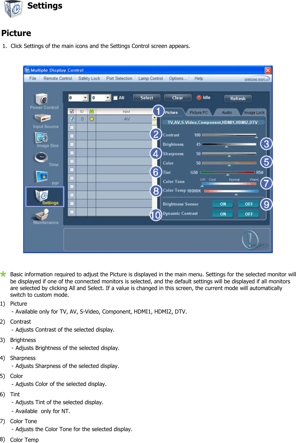
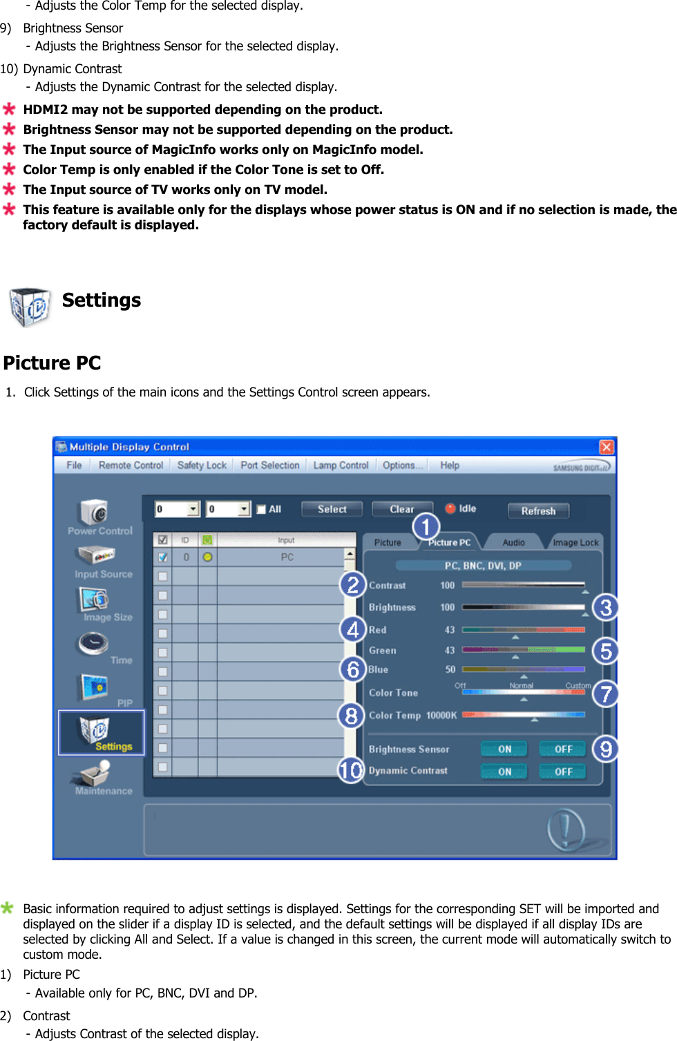
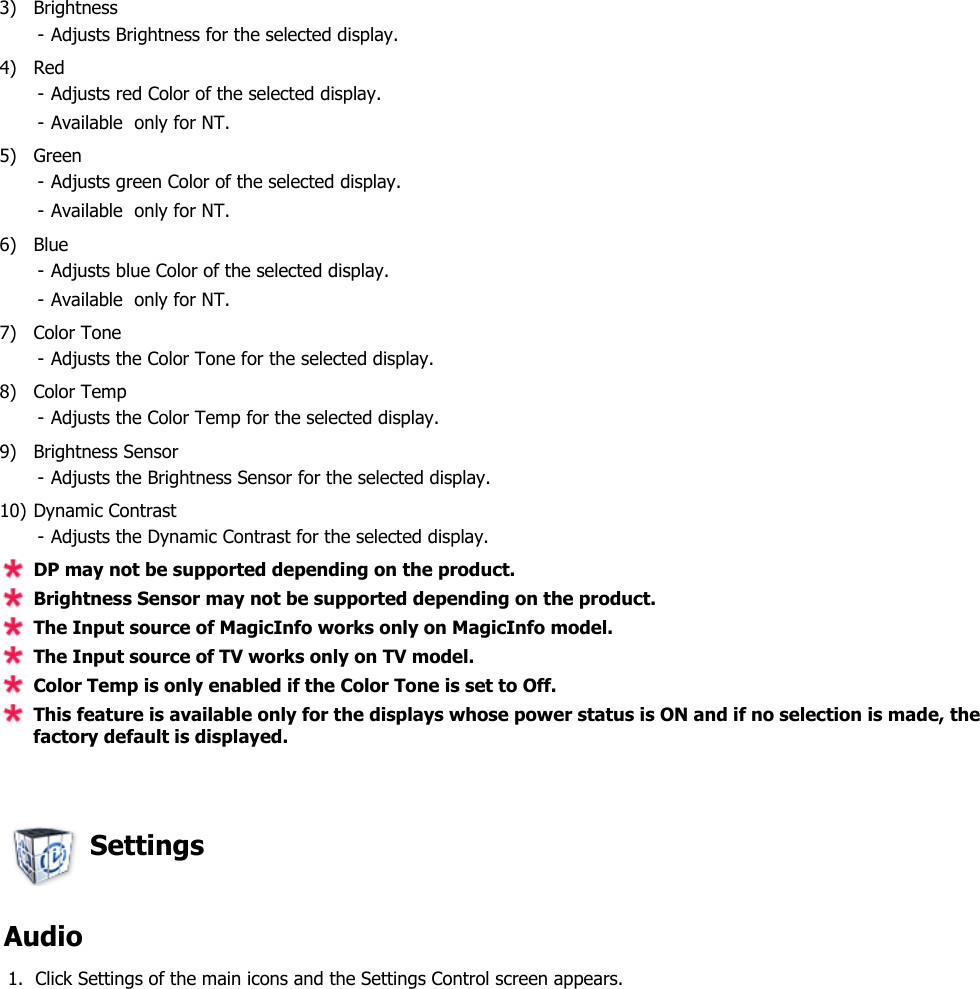
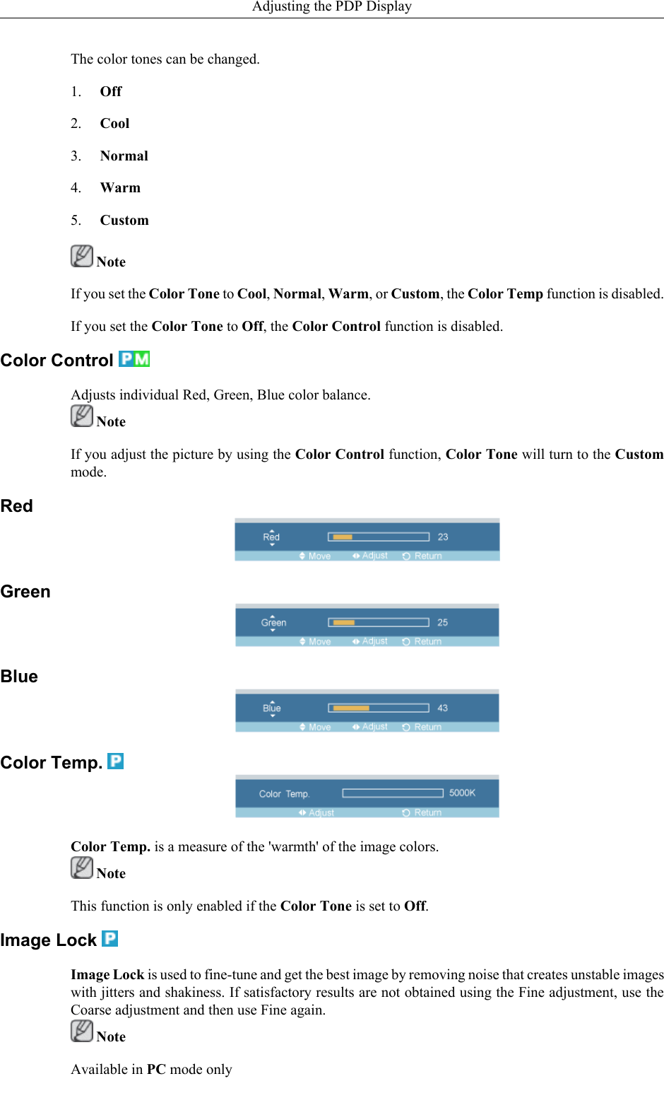
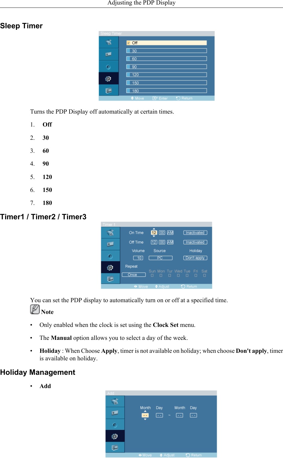
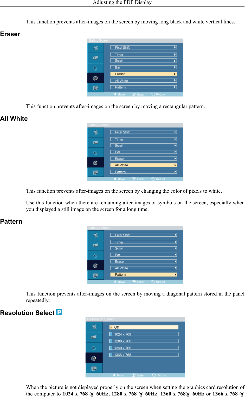
![Name the input device connected to the input jacks to make your input source selection easier.VCR / DVD / Cable STB / HD STB / Satellite STB / AV Receiver / DVD Receiver / Game /Camcorder / DVD Combo / DHR / PC Note• Set Edit Name to PC when a PC is connected via the HDMI or DVI port.In most other cases, set Edit Name to AV.Note that Edit Name should be set to the connected source device if the source device's signal is640 x 480, 720p (1280 x 720), or 1080p (1920 x 1080) because these signals are compatible withboth AV and PC input.• The Picture menu changes depending on the input signal and Edit Name.Picture [PC / DVI / BNC Mode]Available Modes• PC / DVI / BNC• AV• HDMI• Component Note•MagicInfo can only be enabled when a network box is connected.•The HDMI port and network box cannot be connected at the same time.MagicBright The MagicBright function is only enabled in PC mode. The function offers a picture that is twice asbright and vivid as conventional monitors so that users' various needs (to prepare documents, use theInternet, view videos, etc.) are satisfied.Adjusting the PDP Display](https://usermanual.wiki/Samsung-Electronics-Co/IWB-P1/User-Guide-1616926-Page-78.png)
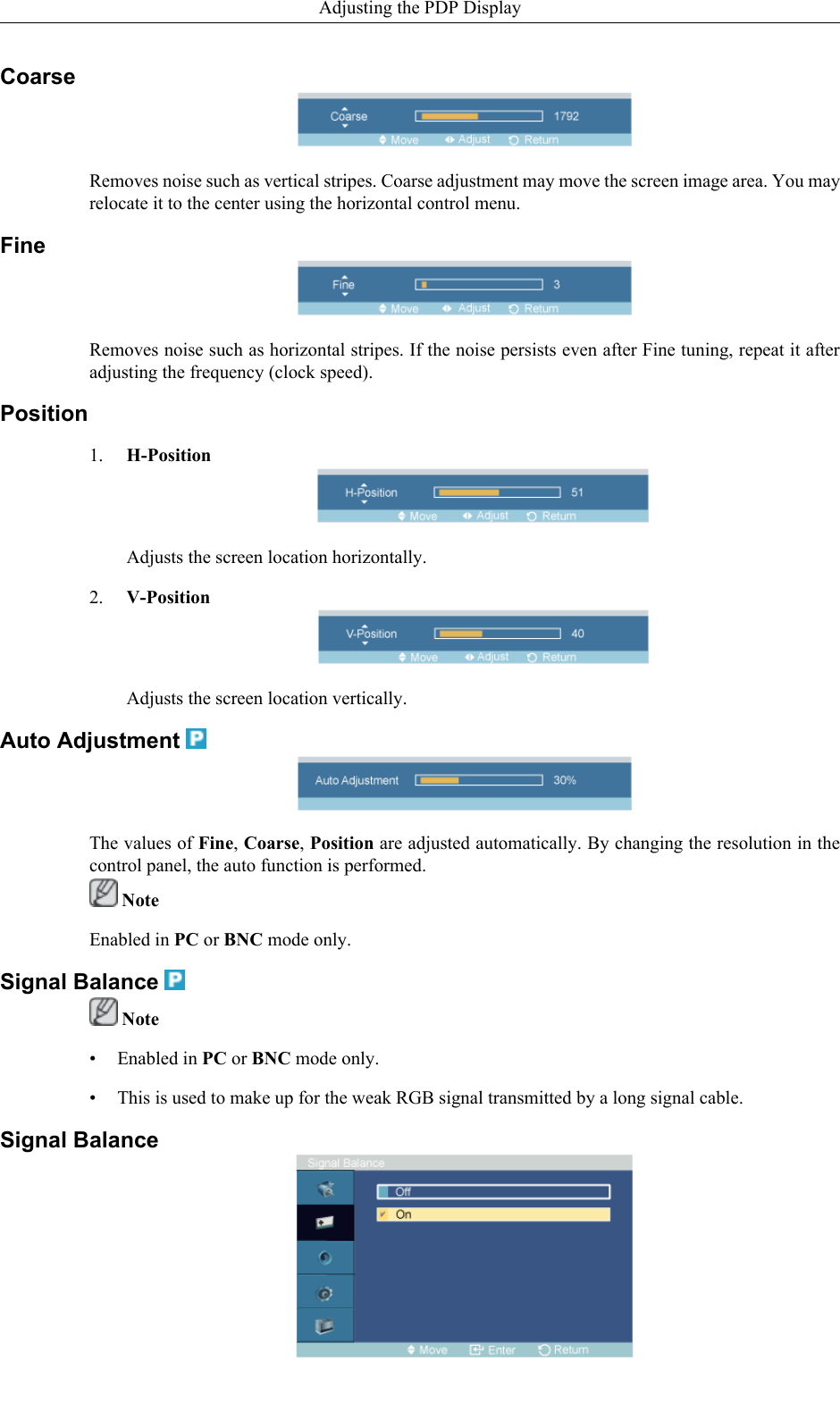
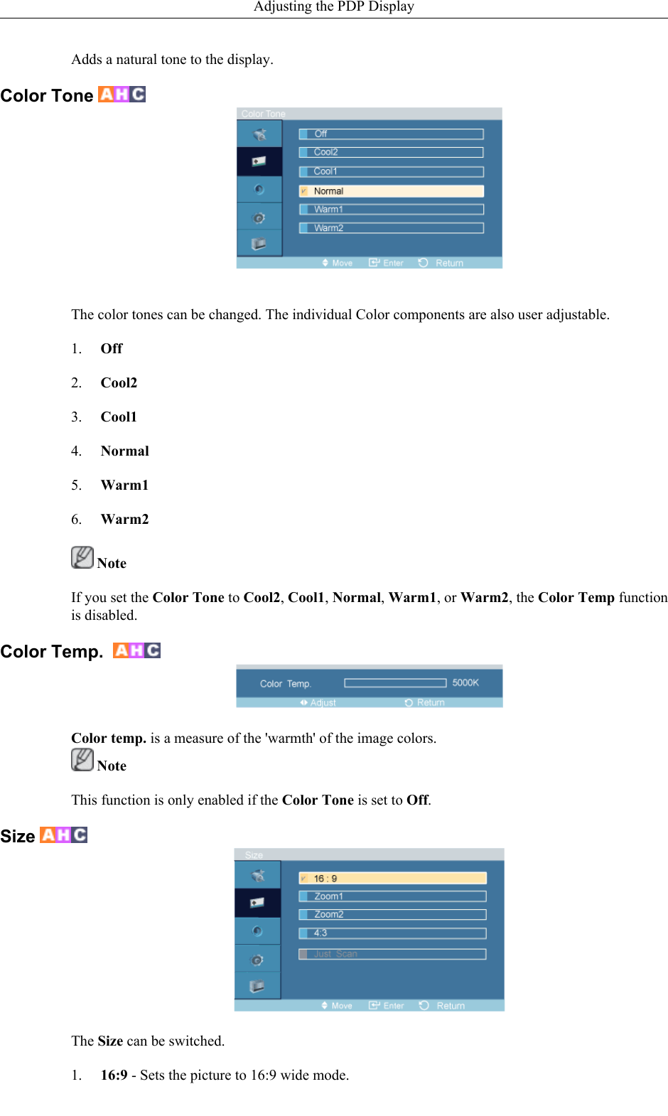
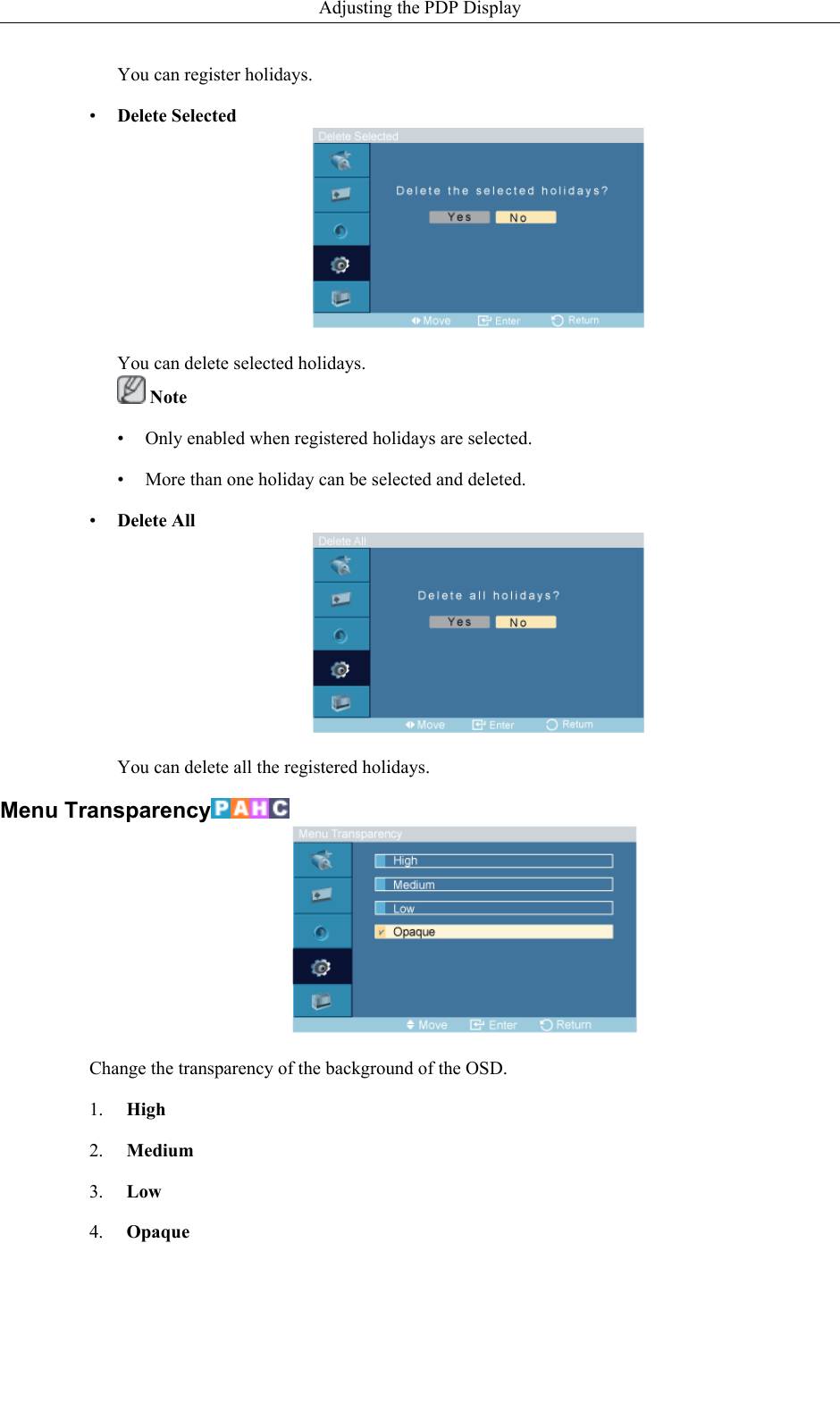
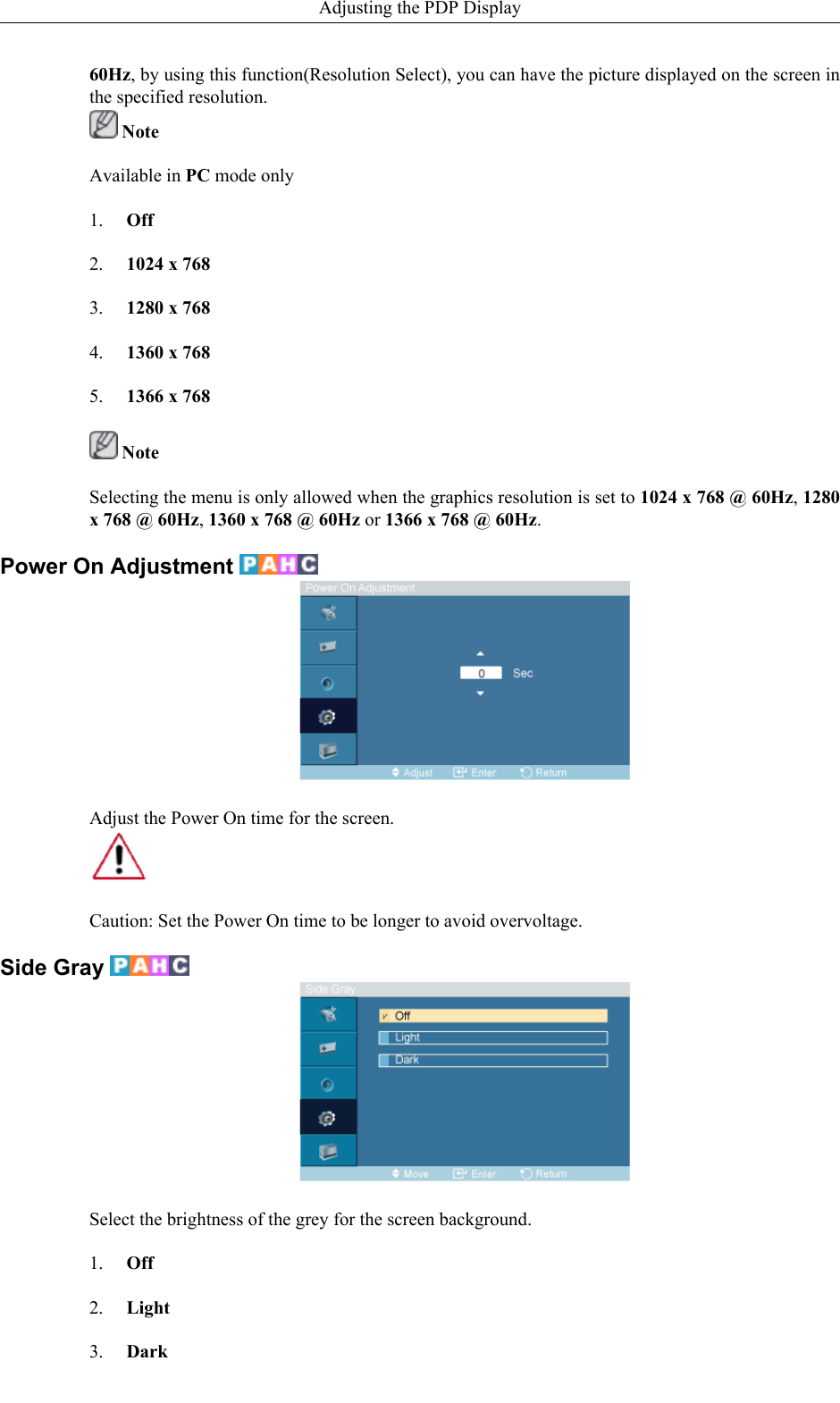
![Selects either On or Off with the signal balance.Signal Control1. R-Gain2. G-Gain3. B-Gain4. R-Offset5. G-Offset6. B-OffsetSize The Size can be switched.1. 16:92. 4:3Picture [ AV / HDMI / Component Mode]Available Modes• PC / DVI / BNC• AV• HDMIAdjusting the PDP Display](https://usermanual.wiki/Samsung-Electronics-Co/IWB-P1/User-Guide-1616926-Page-82.png)
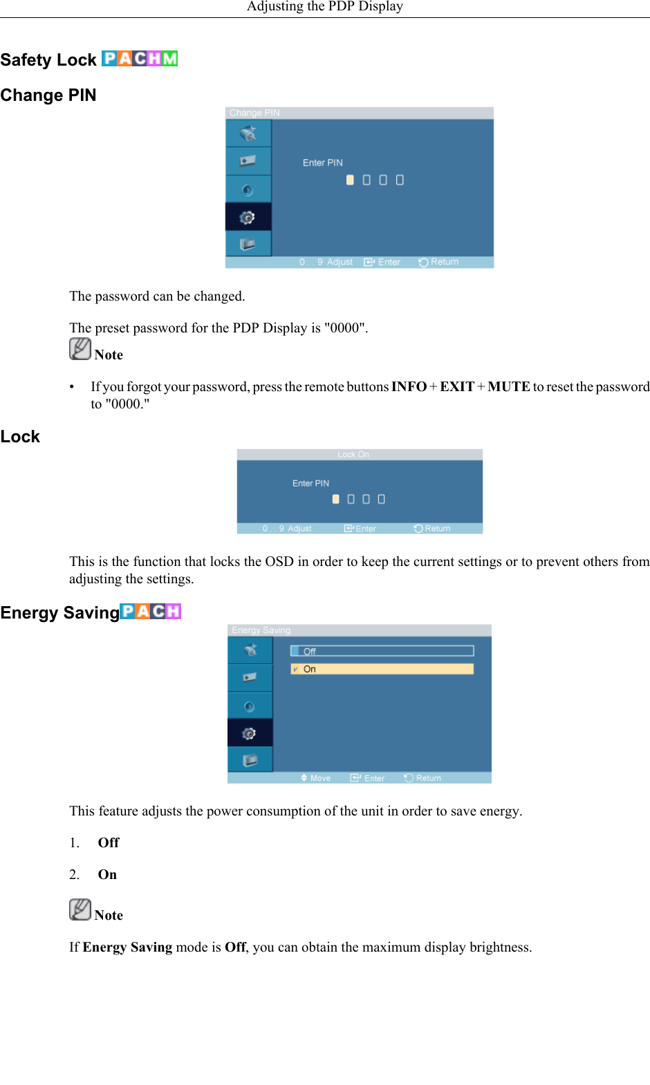
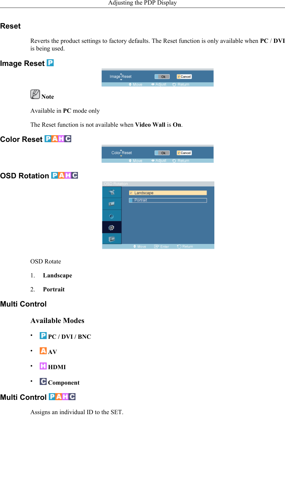
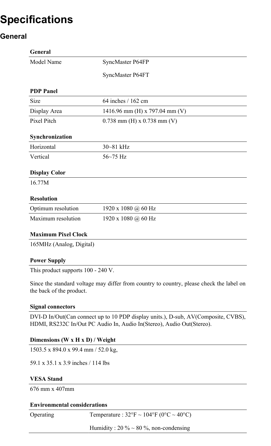
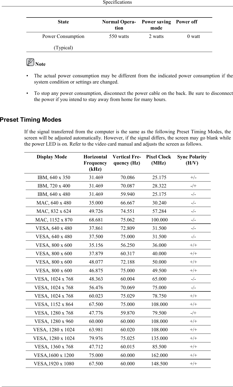
![Environmental considerationsStorage Temperature : -4°F ~ 113°F (-20°C ~ 45°C)Humidity : 5 % ~ 95 %, non-condensingPlug and Play CapabilityThis PDP Display can be installed on any Plug & Play compatible system. The interactionof the PDP Display and the computer systems will provide the best operating conditionsand PDP Display settings. In most cases, the PDP Display installation will proceed auto-matically, unless the user wishes to select alternate settings.Dot AcceptableTFT-LCD panels manufactured by using advanced semiconductor technology with preci-sion of 1ppm (one millionth) above are used for this product. But the pixels of RED,GREEN, BLUE and WHITE Color appear to be bright sometimes or some black pixelsmay be seen. This is not from bad quality and you can use it without any problems.For example, the number of TFT-LCD sub pixels contained in this product are 6,220,800. NoteDesign and specifications are subject to change without prior notice.Class A (Information Communication equipment for industrial use)Attention dealers and users. This device is registered for EMC requirements for industrial use (ClassA) and can be used in areas other than general households.[Recommendation] - EU Only (P64FT Model Only)Hereby, Samsung Electronics, declares that this [PDP Display] is incompliance with the essential requirements and other relevant provisionsof Directive 1999/5/EC(USA only)Dispose unwanted electronics through an approved recycler.To find the nearest recycling location, go to our website:www.samsung.com/recyclingdirect Or call, (877) 278 - 0799PowerSaverThis PDP Display has a built-in power management system called PowerSaver. This system saves byswitching your PDP Display to low-power mode when it has not been used for a certain amount oftime. The PDP Display automatically returns to normal operation when you press a key on the key-board. For energy conservation, turn your PDP Display OFF when it is not needed, or when leaving itunattended for long periods. The PowerSaver system operates with a VESA DPM compliant videocard installed in your computer. Use the software utility installed on your computer to set up this feature.PowerSaverState Normal Opera-tionPower savingmodePower offPower Indicator On Blinking OffSpecifications](https://usermanual.wiki/Samsung-Electronics-Co/IWB-P1/User-Guide-1616926-Page-107.png)