Samsung Electronics Co LXB530 User Manual
Samsung Electronics Co Ltd
UserManual.wiki
>
Samsung Electronics Co
>
LXB530 User Manual
USER MANUAL
Navigation menu
Upload a User Manual
Namespaces
Wiki Guide
HTML
PDF
Info
Views
User Manual
Discussion / Help
Navigation
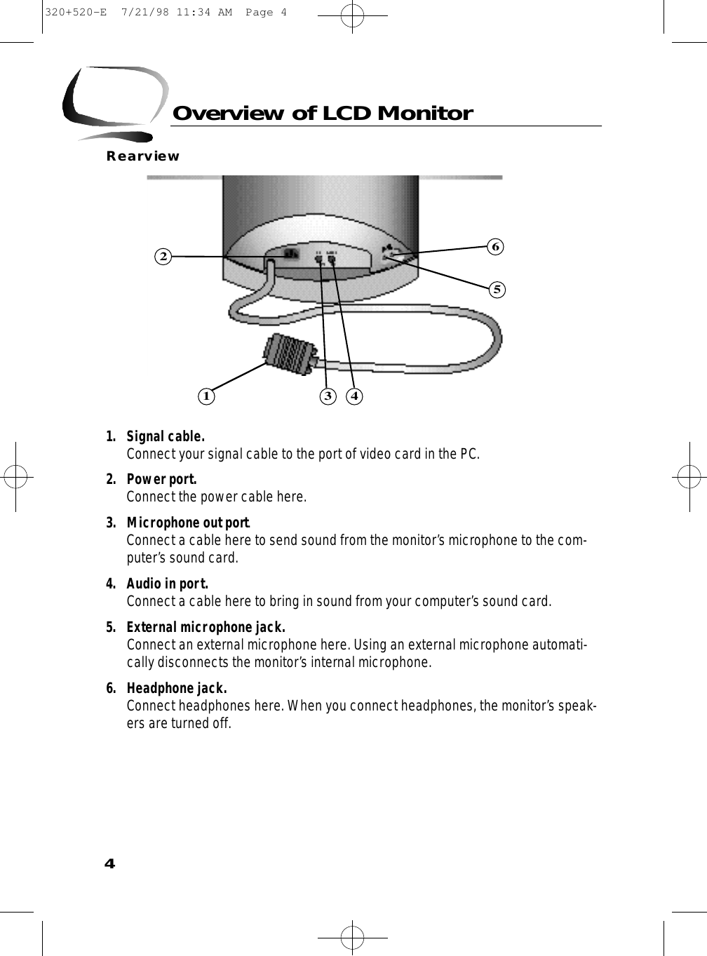
![3Overview of LCD MonitorFrontviewScreen Controls1. Menu [ ] button. Use this button to activate the on-screen display or to enter aselection in the on-screen display.2. Exit button. Use this button to exit the on-screen display.3. Up [ ▲] / Down [ ▼] and –/+ buttons. Use these buttons to choose or adjust items in the on-screen display.4. Power button and Indicator. Use this button to turn the monitor On and Off. The indicator light in the middle ofthe button glows green during normal operation and glows amber while the monitor is in the power saving mode or if the signal cable is disconnected.Audio Controls5. Audio On/Off and Volume. Use this button to turn the sound On and Off and to control the sound volume.6. Bass. Use this button to adjust the volume of the low sounds.7. Treble. Use this button to adjust the volume of the high sounds.8. Microphone On/Off. Use this button to turn the internal microphone On or Off.9. Microphone. Picks up sound and sends it to the sound card in your PC.10. Amplified Stereo Speakes2310569781014320+520-E 7/21/98 11:34 AM Page 3](https://usermanual.wiki/Samsung-Electronics-Co/LXB530/User-Guide-5305-Page-5.png)