Samsung Electronics Co RFD01F-26A RRU (RFD01F) Base Station User Manual RFD01F 26A Ver 1 1 Sprint EN
Samsung Electronics Co Ltd RRU (RFD01F) Base Station RFD01F 26A Ver 1 1 Sprint EN
Contents
- 1. RFD01F-26A_User Manual_Ver.1.1_Sprint_EN
- 2. User Manual
RFD01F-26A_User Manual_Ver.1.1_Sprint_EN

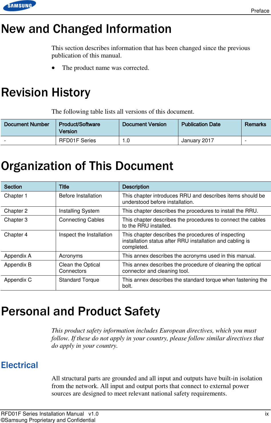

![RFD01F Series Installation Manual v1.0 1 © Samsung Proprietary and Confidential Chapter 1 Before Installation System Configuration and Interface RRU Configuration The configuration of RRU is as follows: Figure 1. RRU Configuration [Bottom View] 12.59 (320) [Front View] [Top View] [Left View] [Right View] [Rear View] 15.09 (383) 7.68 (195) 12.59 (320) Unit: in.(mm)](https://usermanual.wiki/Samsung-Electronics-Co/RFD01F-26A.RFD01F-26A-User-Manual-Ver-1-1-Sprint-EN/User-Guide-3278855-Page-12.png)
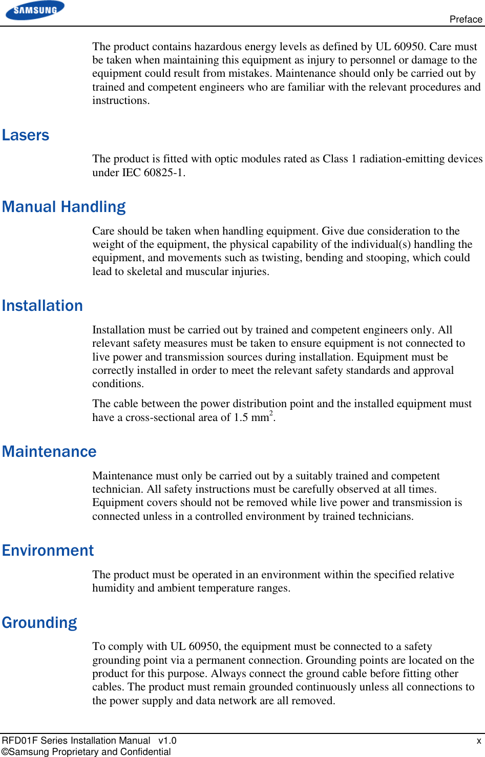
![Chapter 1 Before Installation RFD01F Series Installation Manual v1.0 2 © Samsung Proprietary and Confidential RRU Interface The interface structure of RRU is as follows: Figure 2. RRU Interface ANT0 L1 (CPRI_1) L0 (CPRI_0) DC_PWR [Bottom View] Ground Terminal RET ANT1 ANT2 ANT3](https://usermanual.wiki/Samsung-Electronics-Co/RFD01F-26A.RFD01F-26A-User-Manual-Ver-1-1-Sprint-EN/User-Guide-3278855-Page-13.png)
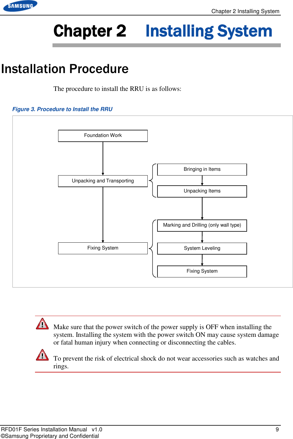
![Chapter 2 Installing System RFD01F Series Installation Manual v1.0 10 © Samsung Proprietary and Confidential System Arrangement A minimum distance must be secured around the RRU, in each direction for installation and maintenance. Figure 4. RRU_Wall Type Standard Installation [Top View] [Front View] 11.31 (287.5) 12.59 (320) 15.10 (383) ≥8(200) ≥12(300) ≥12(300) ≥16(400) Wall ≥32(800) Wall RRU Unit: in.(mm)](https://usermanual.wiki/Samsung-Electronics-Co/RFD01F-26A.RFD01F-26A-User-Manual-Ver-1-1-Sprint-EN/User-Guide-3278855-Page-21.png)
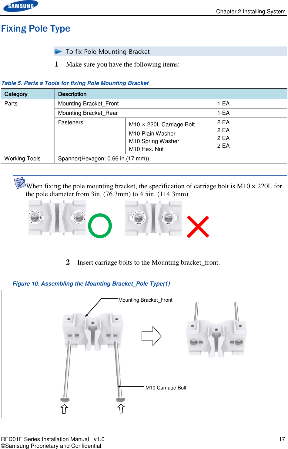
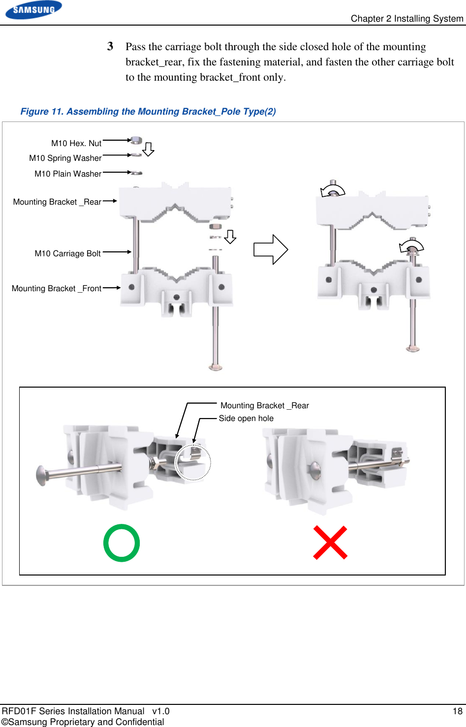
![Chapter 2 Installing System RFD01F Series Installation Manual v1.0 11 © Samsung Proprietary and Confidential Figure 5. RRU Arrangement_Pole Type Installation [Top View] [Front View] [Side Installation] [Standard Installation] 18.03 (458) 12.59 (320) 15.10 (383) 22.95 (583) 15.10 (383) 7.68 (195) [Side View] Front ≥8 (200) ≥8 (200) ≥32 (800) Pole (Φ 3~4.5 (76.3~114.3)) ≥8 (200) ≥8 (200) Pole Front Pole ≥32 (800) Pole Pole Unit: in.(mm) Pole (Φ 3~4.5 (76.3~114.3)) ≥12 (300) ≥12 (300) ≥12 (300) ≥12 (300)](https://usermanual.wiki/Samsung-Electronics-Co/RFD01F-26A.RFD01F-26A-User-Manual-Ver-1-1-Sprint-EN/User-Guide-3278855-Page-22.png)
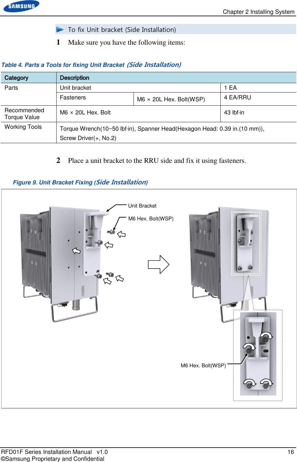
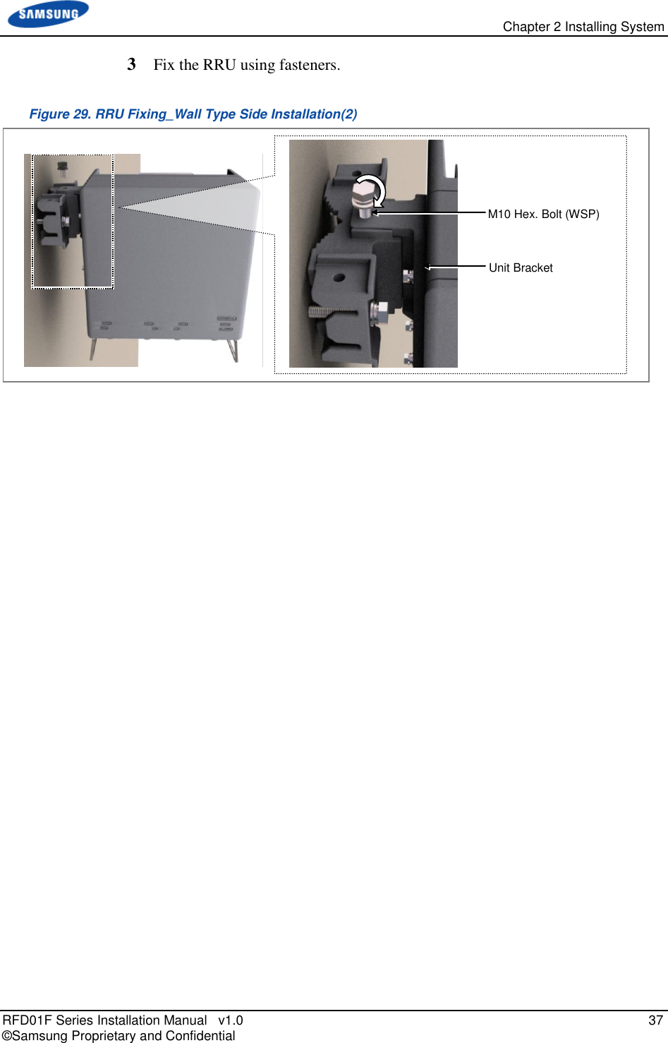
![Chapter 2 Installing System RFD01F Series Installation Manual v1.0 14 © Samsung Proprietary and Confidential Fixing RRU Fixing Unit Bracket There are two ways to fix a unit bracket to the RRU. One is fixing a unit mounting bracket to the rear side of RRU (Standard installation). The other is fixing a unit bracket to the side of RRU (Side installation). These are the same for the wall type and pole type installation procedures. Figure 7. Unit Bracket Fixing Type [Unit Bracket Standard Installation] [Unit Bracket Side Installation] Unit Bracket](https://usermanual.wiki/Samsung-Electronics-Co/RFD01F-26A.RFD01F-26A-User-Manual-Ver-1-1-Sprint-EN/User-Guide-3278855-Page-25.png)
![Chapter 2 Installing System RFD01F Series Installation Manual v1.0 19 © Samsung Proprietary and Confidential To lift RRU/Pole Mounting Bracket Assembly_Pole Type 1 Tie the rope in two carrying points. Figure 12. Lifting RRU & Pole Mounting Bracket Assembly_Pole Type(1) Carrying Point_1 Carrying Point_2 [RRU] Carrying Point_1 Carrying Point_2 [Pole Mounting Bracket Assembly]](https://usermanual.wiki/Samsung-Electronics-Co/RFD01F-26A.RFD01F-26A-User-Manual-Ver-1-1-Sprint-EN/User-Guide-3278855-Page-30.png)
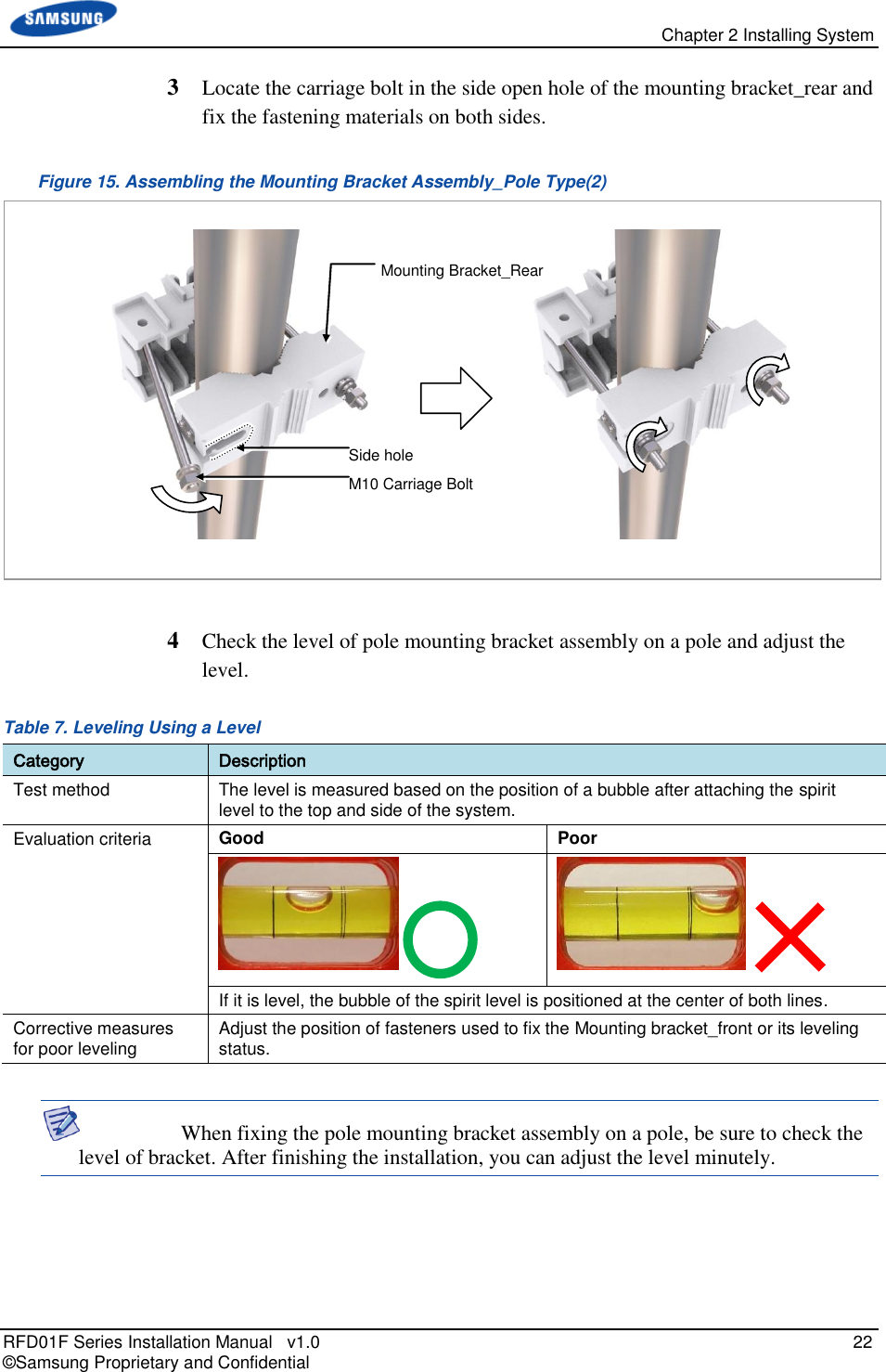
![Chapter 2 Installing System RFD01F Series Installation Manual v1.0 23 © Samsung Proprietary and Confidential Figure 16. Leveling Pole Mounting Bracket Assembly [Measuring vertical position] [Measuring horizontal position]](https://usermanual.wiki/Samsung-Electronics-Co/RFD01F-26A.RFD01F-26A-User-Manual-Ver-1-1-Sprint-EN/User-Guide-3278855-Page-34.png)
![Chapter 2 Installing System RFD01F Series Installation Manual v1.0 29 © Samsung Proprietary and Confidential 2 Check the location and anchor hole distance for fixing the system. Figure 21. RRU dimensions for Wall Type (Standard Installation) Figure 22. RRU dimensions for Wall Type (Side Installation_ [Rear View] Anchor Bolt Hole Unit: in.(mm) 5.12(130) 12(305) 7.68(195) 3.10(78.5) 15.10(383) M10 Anchor Bolt Hole Unit: in.(mm) 5.12(130) 12.59(320) 3.10(78.5) 15.10(383) M10 Anchor Bolt Hole [Rear View] 3.74(95) 3.74(95) 12(305) Anchor Bolt Hole](https://usermanual.wiki/Samsung-Electronics-Co/RFD01F-26A.RFD01F-26A-User-Manual-Ver-1-1-Sprint-EN/User-Guide-3278855-Page-40.png)
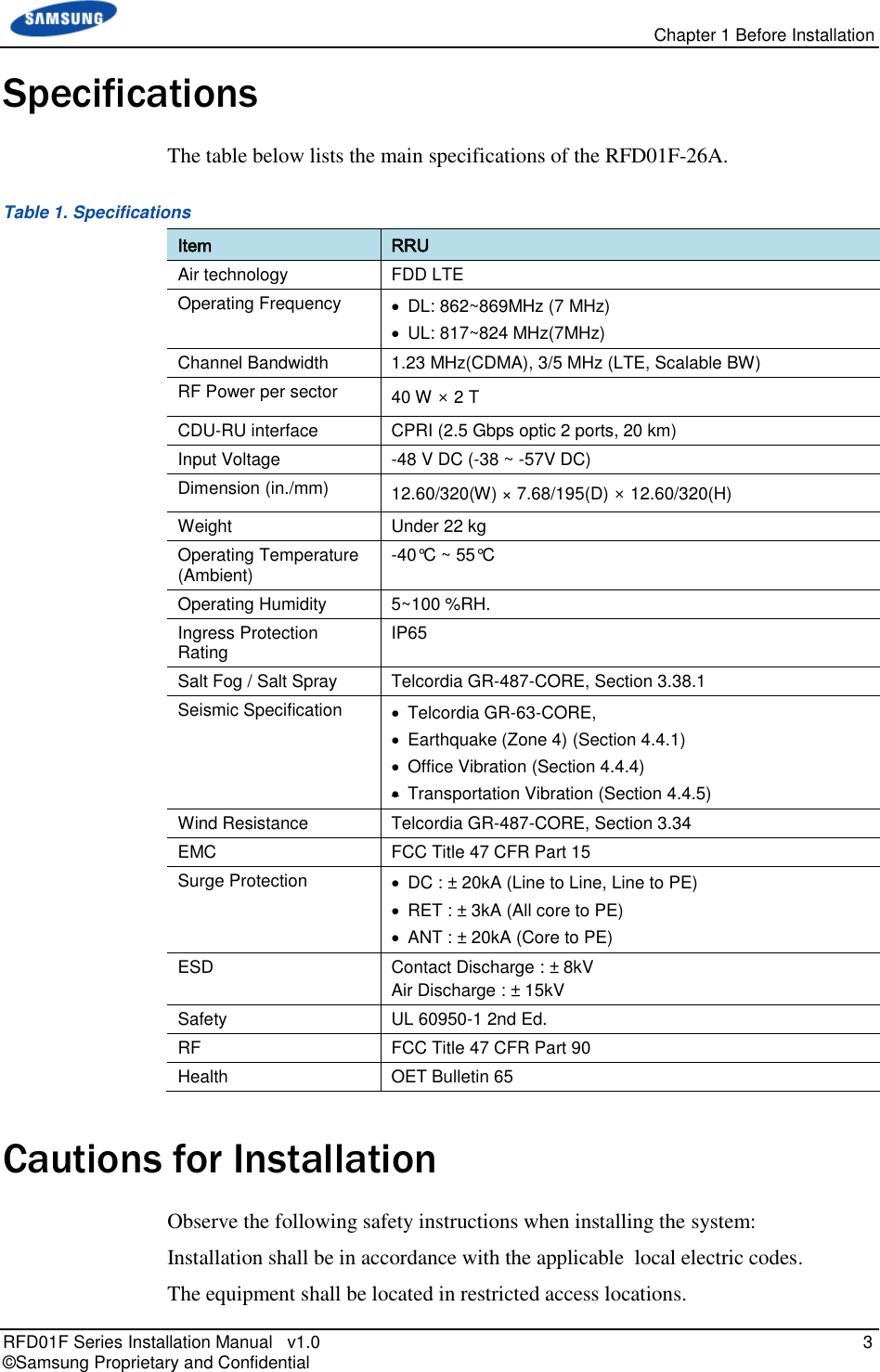
![Chapter 2 Installing System RFD01F Series Installation Manual v1.0 31 © Samsung Proprietary and Confidential To drill anchor holes and fix anchors 1 Make sure that you have the following items: Table 11. Parts and Tools for Drilling & Fixing Anchor Category Description Parts M10 Strong Anchor 2 EA Woking Tools Hammer Drill, Concrete Drill Bit(0.55 in.(14 mm)), Vacuum Cleaner, Hammer, Anchor Punch(For M10 Set Anchor) Table 12. Anchor Bolt Drill Bits and Hole Depth Category Anchor Bolt Drill Bits Hole Depth RRU (Wall Type) M10 0.55 in.(14 mm) 1.73 in.(44 mm) 2 Drill anchor holes at marked points with removing dust from the holes using a cleaner. Figure 24. Drilling & Anchoring Example M10 Anchor Bolt Hammer Anchor Punch Hammer Drill 0.55 in. (14 mm) Vacuum Cleaner [O] * Remove the debris from the drilled hole. [Anchor Hole Cross Section] 1.73 in. (44mm) [X] 0.55 in.(14 mm)](https://usermanual.wiki/Samsung-Electronics-Co/RFD01F-26A.RFD01F-26A-User-Manual-Ver-1-1-Sprint-EN/User-Guide-3278855-Page-42.png)
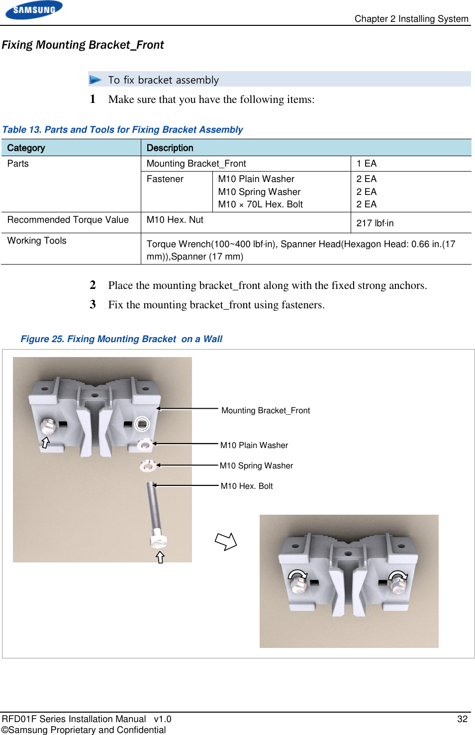
![Chapter 2 Installing System RFD01F Series Installation Manual v1.0 33 © Samsung Proprietary and Confidential When fixing the mounting bracket_front on a wall, the clearances between the wall and left (A)/right (B) sides of mounting bracket_front should be the same. [Top View] B A Wall Mounting Bracket_Front](https://usermanual.wiki/Samsung-Electronics-Co/RFD01F-26A.RFD01F-26A-User-Manual-Ver-1-1-Sprint-EN/User-Guide-3278855-Page-44.png)
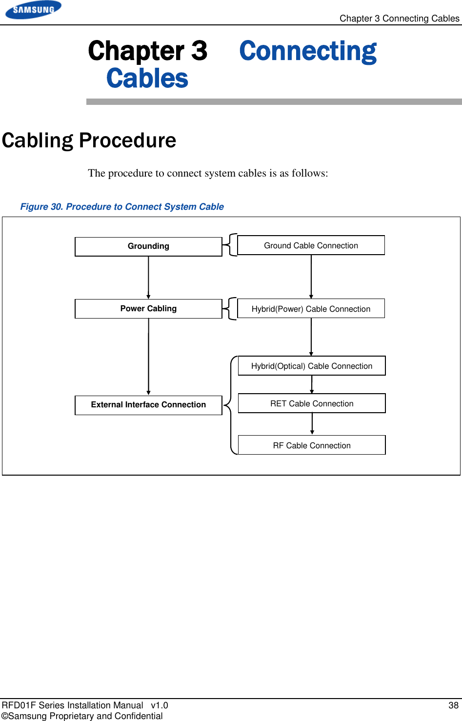
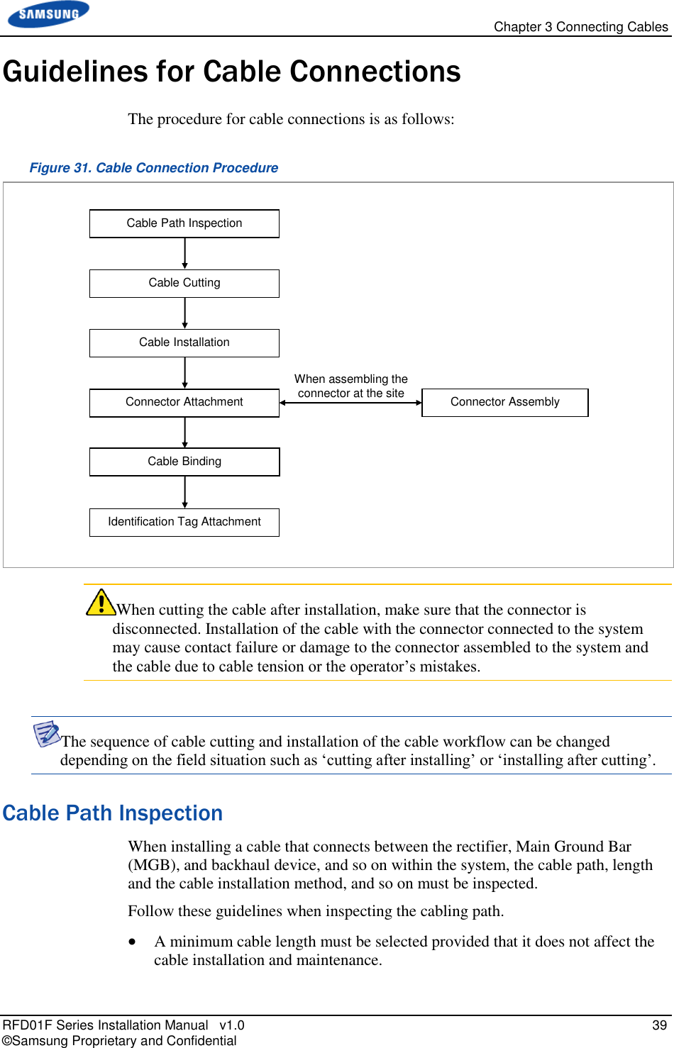
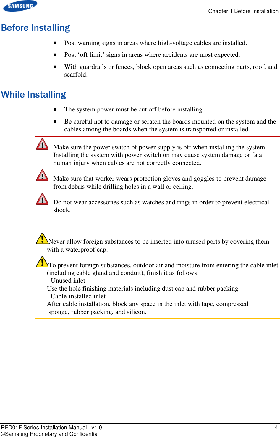
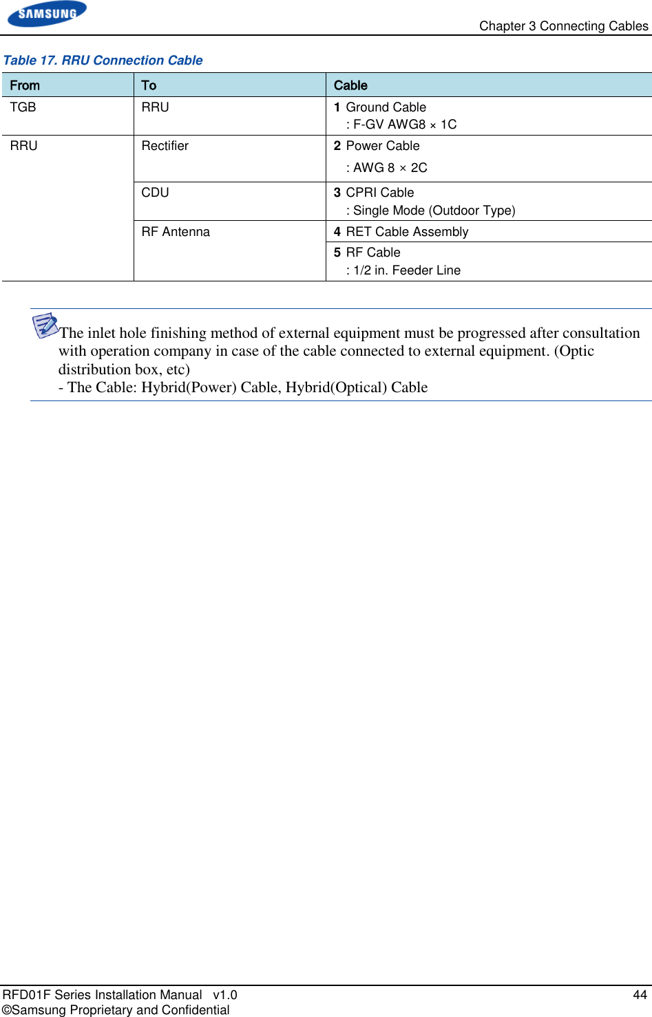
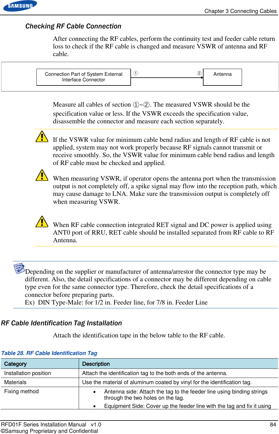
![Chapter 3 Connecting Cables RFD01F Series Installation Manual v1.0 43 © Samsung Proprietary and Confidential Cabling Diagram The cabling diagram of the RRU is as follows: Figure 32. Cable Diagram [RF Antenna] 2) Power Hybrid Cable 3) Optic Hybrid Cable 5) RF Cable TGB 1) Ground Cable 4) RET Cable Rectifier CDU Hybrid Cable](https://usermanual.wiki/Samsung-Electronics-Co/RFD01F-26A.RFD01F-26A-User-Manual-Ver-1-1-Sprint-EN/User-Guide-3278855-Page-54.png)
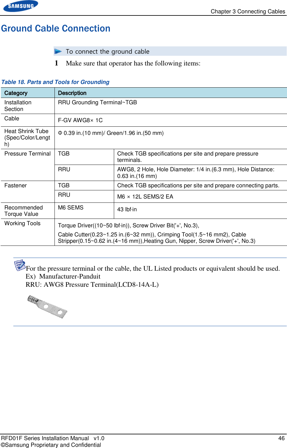
![Chapter 3 Connecting Cables RFD01F Series Installation Manual v1.0 47 © Samsung Proprietary and Confidential 2 Install a ground cable from the TGB to the RRU ground terminal. Figure 33. Ground Cable Connection (1) 3 Align the pressure terminal to the mounting hole of the RRU ground terminal. 4 Firmly fix the pressure terminal onto the RRU ground terminal using Hex. +type. Figure 34. Ground Cable Connection (2) Ground Cable Heat Shrink Tube(Green) Pressure Terminal M6 SEMS(Hex. +) RRU Ground terminal [Bottom View] MGB RRU Ground Cable](https://usermanual.wiki/Samsung-Electronics-Co/RFD01F-26A.RFD01F-26A-User-Manual-Ver-1-1-Sprint-EN/User-Guide-3278855-Page-58.png)
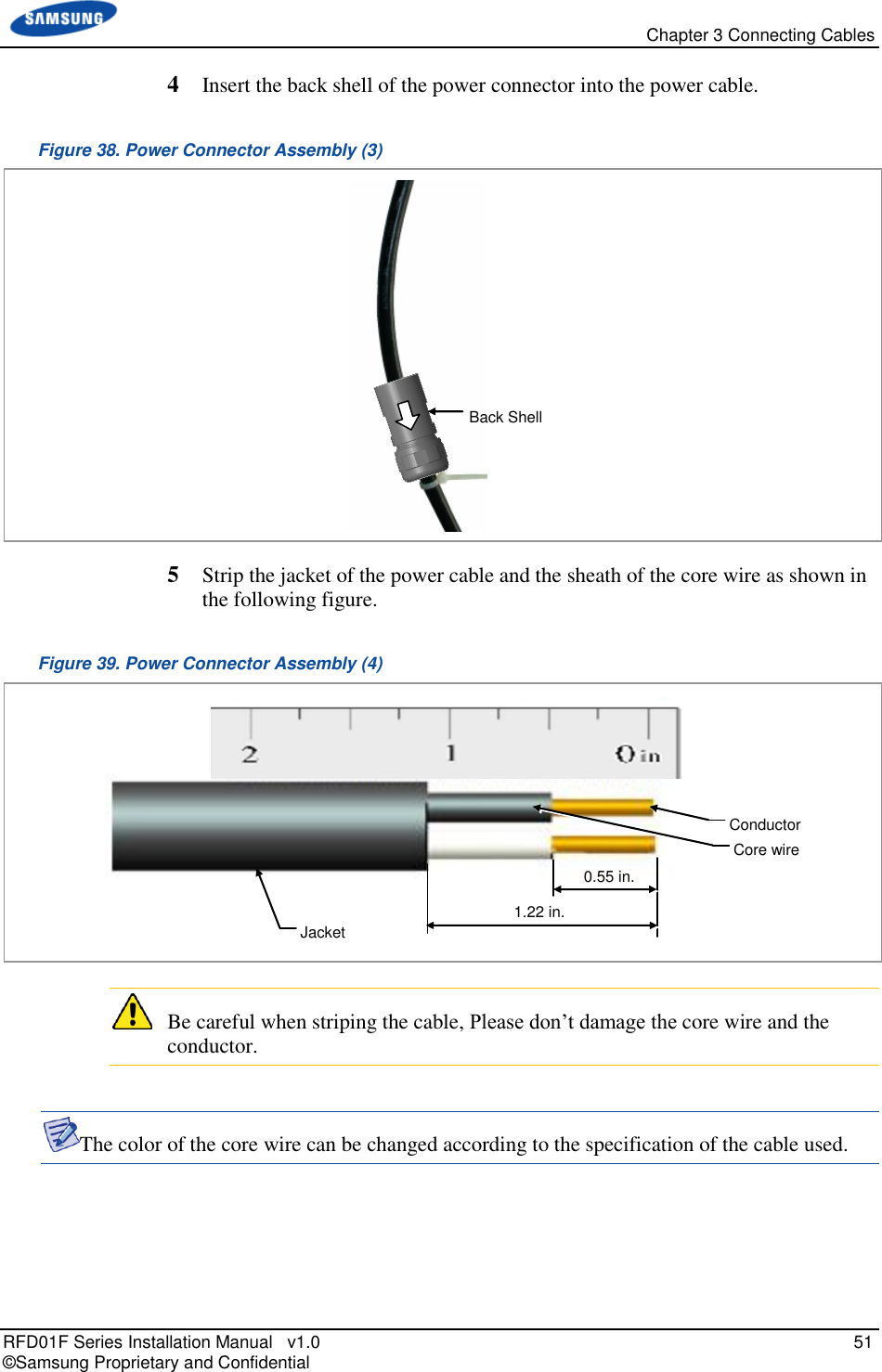
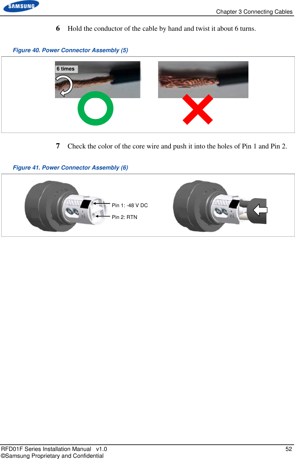
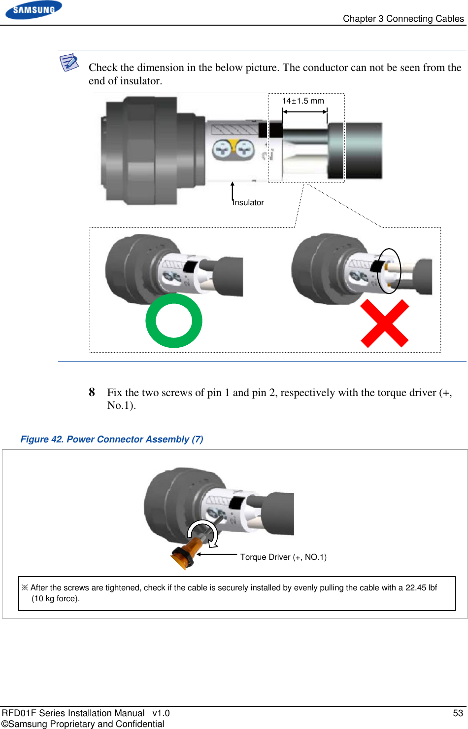
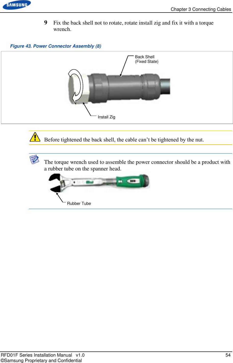
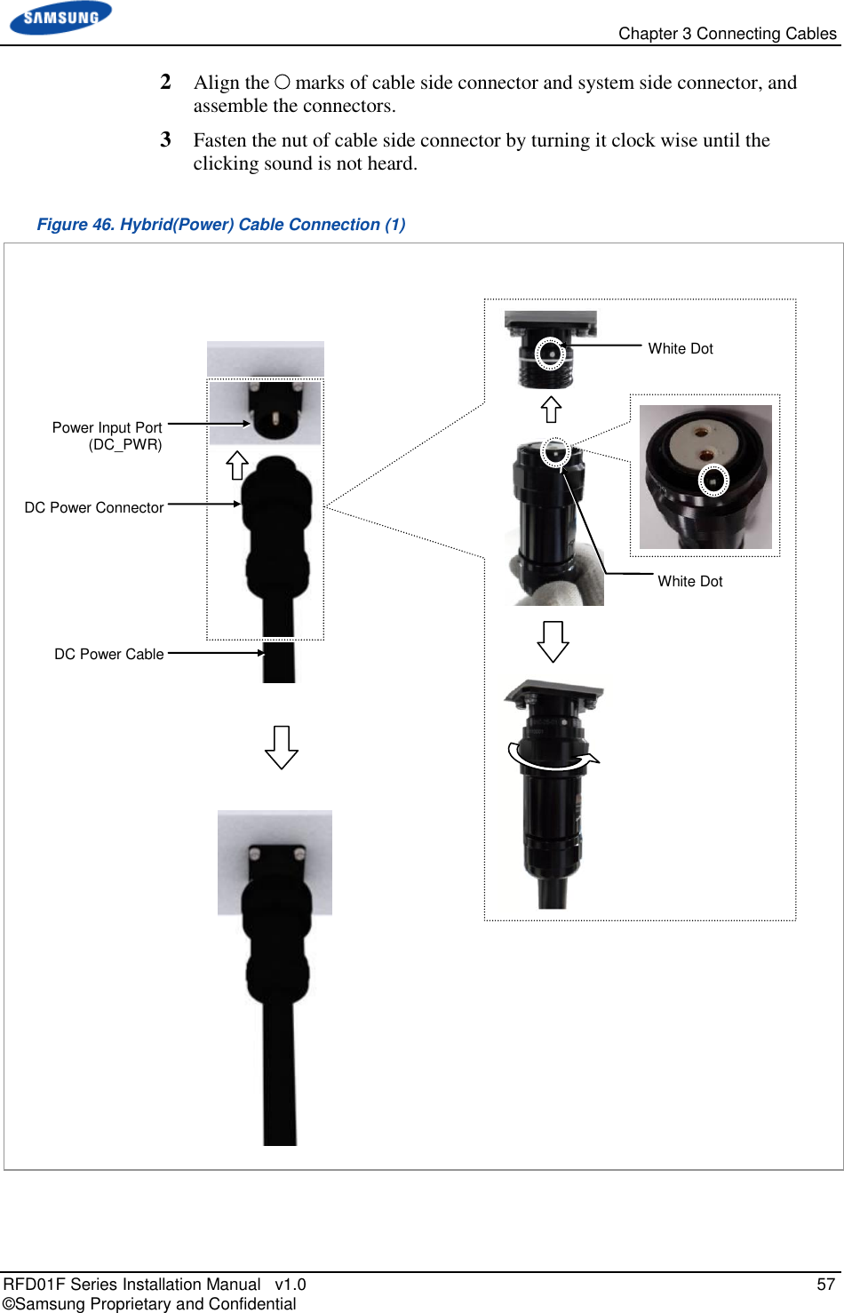
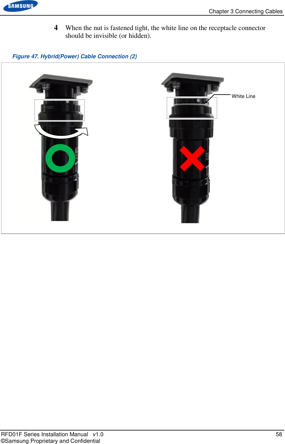
![Chapter 3 Connecting Cables RFD01F Series Installation Manual v1.0 55 © Samsung Proprietary and Confidential 10 Fix the back shell not to rotate, rotate nut and fix it with a torque wrench. Figure 44. Power Connector Assembly (9) 11 Check electrical isolation with a Multi tester. o Pin 1 & Pin 2 o Pin 1/Pin 2 & Back shell Figure 45. Power Connector Assembly (10) 12 After completing the assembly of the power connector, remove the cable tie from the cable. [Pin 1 & Pin 2] [Pin 1 / Pin 2 & Back Shell] Back Shell (Fixed State) Nut](https://usermanual.wiki/Samsung-Electronics-Co/RFD01F-26A.RFD01F-26A-User-Manual-Ver-1-1-Sprint-EN/User-Guide-3278855-Page-66.png)
![Chapter 3 Connecting Cables RFD01F Series Installation Manual v1.0 56 © Samsung Proprietary and Confidential To connect Power cable 1 Make sure that you have the following items: Table 20. Parts and Tools for Power Cable Connection Category Description Installation Section RRH Power Input Port~Rectifier Cable AWG8 × 2C Connector JONHON, CT48C-2T-07 1 -48 V DC 2 RTN Table 21. Power Cable/Connector Pin Map Power Connector Pin No. Description Color 1 -48 V DC If the color coding is needed for the cable, comply with the specifications which have been agreed with the service provider. 2 RTN To prevent foreign substances, air and moisture from entering the cable inlet (including cable gland and conduit), finish it as follows: - Unused inlet Use the hole finishing materials including waterproof cap and rubber packing. - Cable-installed inlet After cable installation, block any space in the inlet with tape, compressed sponge, rubber packing and silicon. [Cable side Connector: JONHON, CT48C-2T-07] [System side Connector: JONHON, CT48C-2S-01] 1 2 1 2](https://usermanual.wiki/Samsung-Electronics-Co/RFD01F-26A.RFD01F-26A-User-Manual-Ver-1-1-Sprint-EN/User-Guide-3278855-Page-67.png)
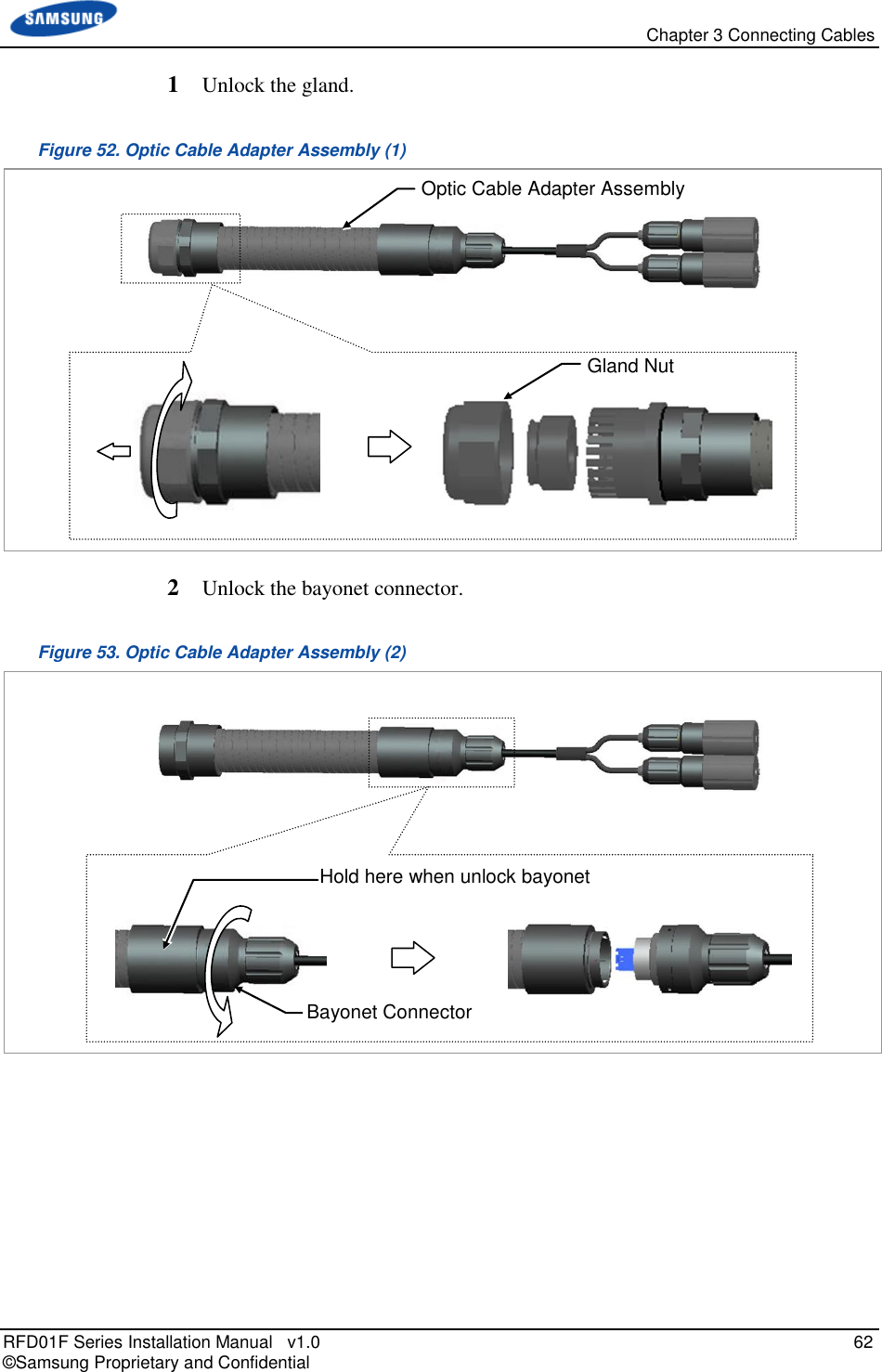
![Chapter 3 Connecting Cables RFD01F Series Installation Manual v1.0 59 © Samsung Proprietary and Confidential Interface Cable Connection Remove/Insert Optic Module If the optic module needs to be removed or inserted before connecting the cable, follow the below process. To remove Optical Module 1 Hang the jig hook on the optic module’s bail within the system. Figure 48. Optic Module Removal (1) 2 Completely remove the optic module from the transceiver by pulling the jig. Figure 49. Optic Module Removal (2) 3 Remove the optic module and the jig by pressing the jig's hook grip. Figure 50. Optic Module Removal (3) Jig Optic Module Transceiver Jig Optic Connector Optic Module [System Inside] Jig (Hook) Bail [Front View] Location to hang the Jig](https://usermanual.wiki/Samsung-Electronics-Co/RFD01F-26A.RFD01F-26A-User-Manual-Ver-1-1-Sprint-EN/User-Guide-3278855-Page-70.png)
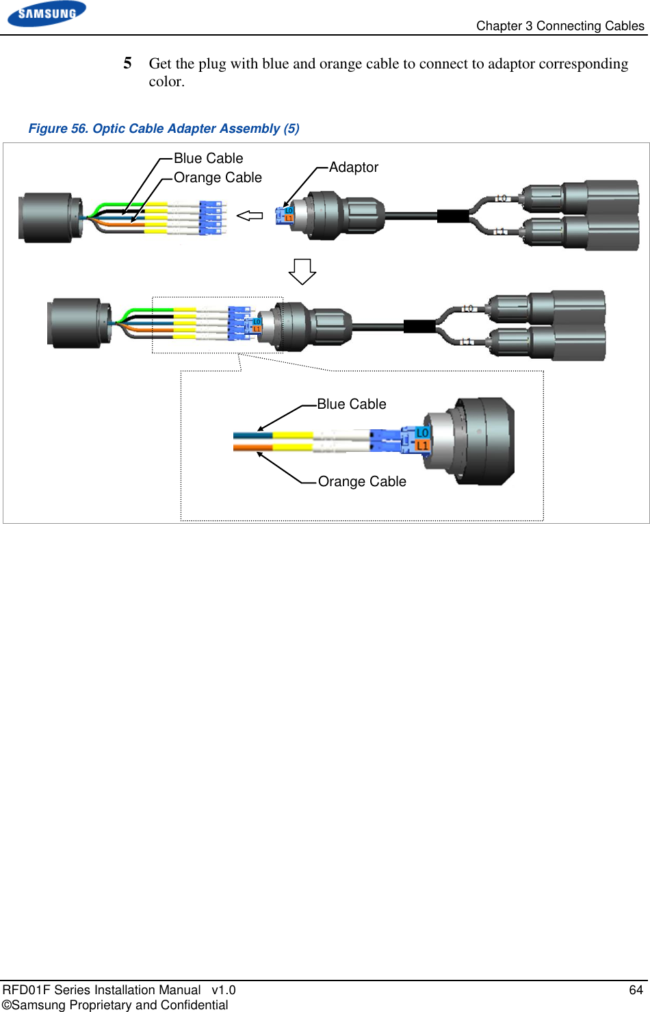
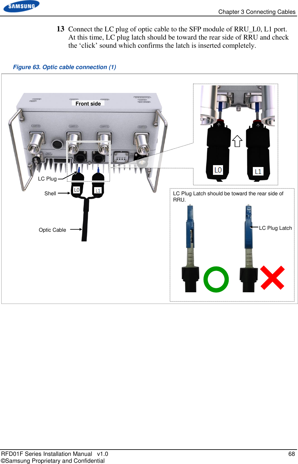
![Chapter 3 Connecting Cables RFD01F Series Installation Manual v1.0 60 © Samsung Proprietary and Confidential To inset Optic Module Push the optic module into the transceiver within the connector. Figure 51. Optic Module Inset Inset the optic module's bail, facing the front of the system, to the port. Do not inset when the optic module's bail is unlocked. Optic Cable Connection To connect optic cable 1 Make sure that you have the following items: Table 22. Parts and Tools for Optic Cable Adapter Assembly Category Description Parts Optic Cable Adapter Assembly 1 Set Recommended Torque Value Gland Nut 17.70 lbf·in Working Tools Adjustable Torque Wrench(10~50 lbf.in.), Adjustable Spanner (Hexagon Head: 2.04 Optic Module Bail [Raised: Lock] [Lowered: Unlock] Optic Module Bail [System Inside] Transceiver Optic Module Optic Connector](https://usermanual.wiki/Samsung-Electronics-Co/RFD01F-26A.RFD01F-26A-User-Manual-Ver-1-1-Sprint-EN/User-Guide-3278855-Page-71.png)
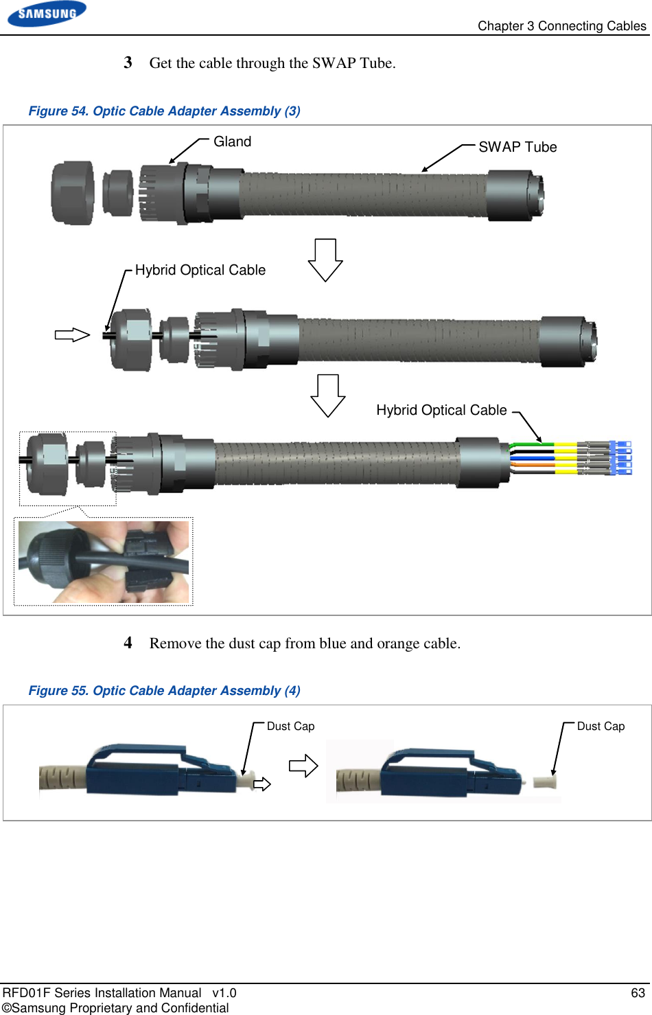
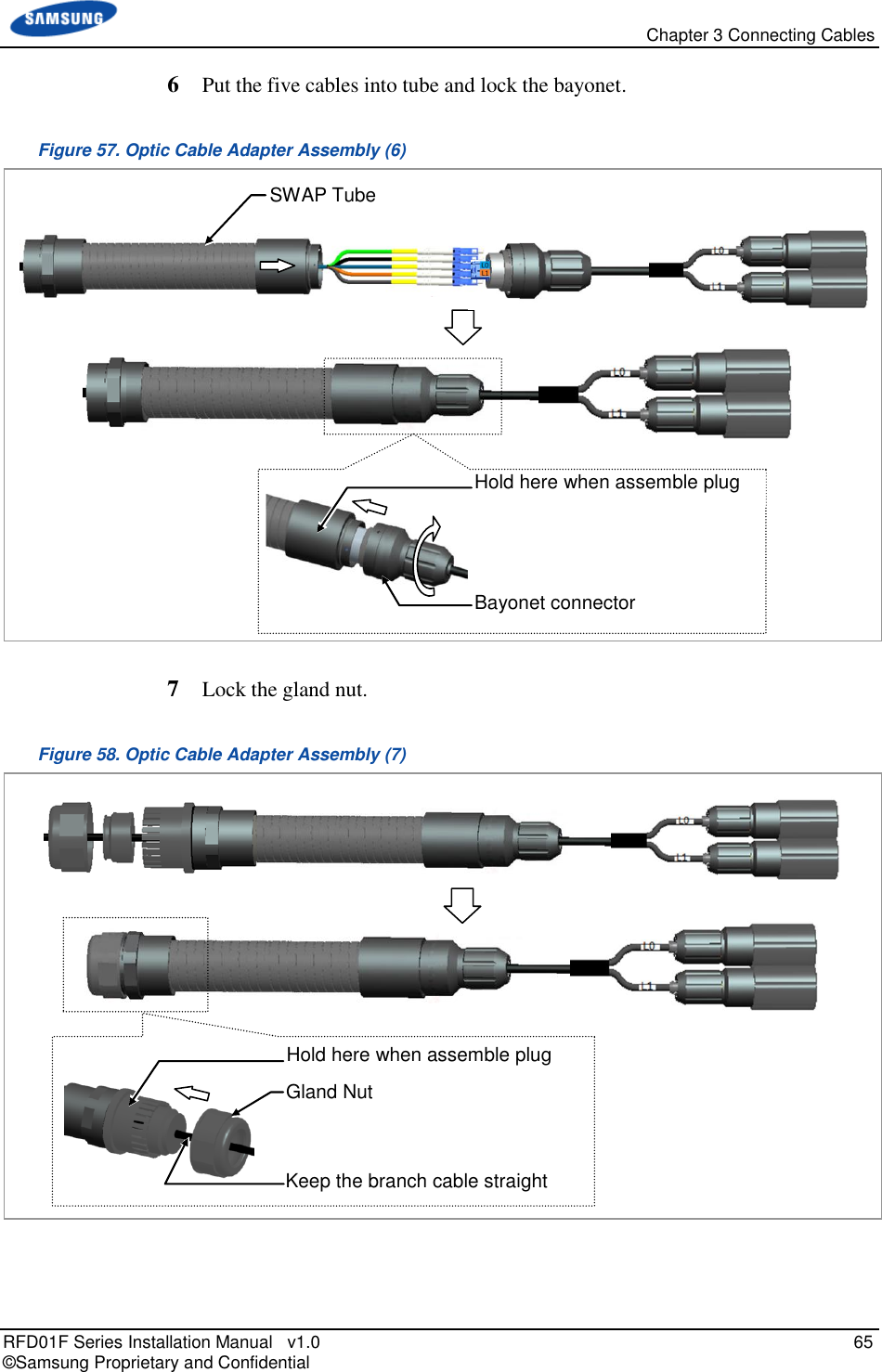
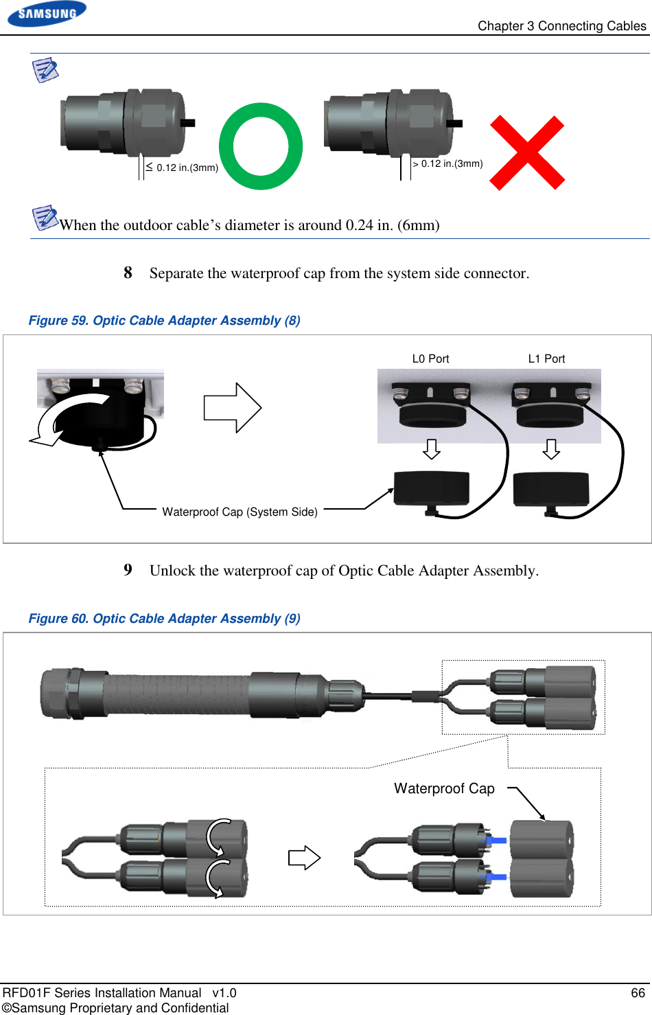
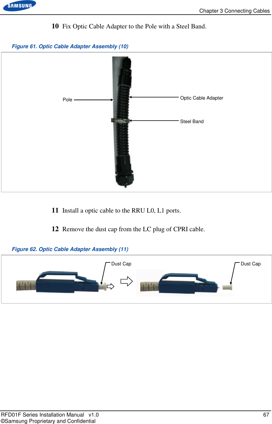
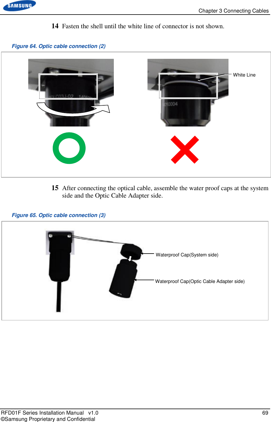
![Chapter 3 Connecting Cables RFD01F Series Installation Manual v1.0 61 © Samsung Proprietary and Confidential Category Description in.(52mm)) In the system, the laser beam light runs through the optical cable. The exposure of the laser beam on worker’s eye may cause serious injury so that it should be handled with care. Remove the dust cap of the optical connector before connecting. - Before connecting the optical cable, check if the ferrule of the connector is soiled. Be careful to keep the cutting section away from dust or foreign material. If the cable is soiled with foreign material, do not blow to remove them. - Make sure to clean the connector in accordance with the cleaning directions in Annex. - Do not touch the ferrule at the end of optical cable because it is easy to be damaged. [Before Removing Dust Cap] [After Removing Dust Cap] Dust Cap Ferrule Water Proof Cap Bayonet Connector Gland](https://usermanual.wiki/Samsung-Electronics-Co/RFD01F-26A.RFD01F-26A-User-Manual-Ver-1-1-Sprint-EN/User-Guide-3278855-Page-72.png)
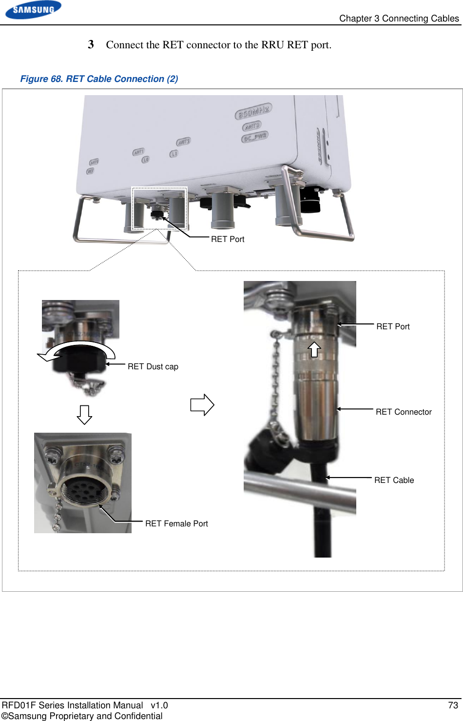
![Chapter 3 Connecting Cables RFD01F Series Installation Manual v1.0 71 © Samsung Proprietary and Confidential RET Cable Connection To connect the RET cable 1 Make sure operator has the following items: Table 23. Parts for RET Cable Connection Category Description Installation Section RRU RET port~RF Antenna Cable RET Cable Assembly Connector RRU AISG 2.0 RF Antenna Check the RF antenna (RETu) RET connector specification per site Table 24. RET Cable Pin Map Pin No Description Cable Color 1 N/C (Not Connected) - 2 N/C (Not Connected) - 3 RS485 B White 4 GND Blue 5 RS485 A Brown 6 +24 V DC Red 7 DC Return Black 8 N/C (Not Connected) - Before fitting the RET connector, make sure to align the female connector’s hole with the male connector’s pin first. [Male Connector] [Female Connector] Hole Pin [Male: RRU Side] [Female: Antenna Side]](https://usermanual.wiki/Samsung-Electronics-Co/RFD01F-26A.RFD01F-26A-User-Manual-Ver-1-1-Sprint-EN/User-Guide-3278855-Page-82.png)
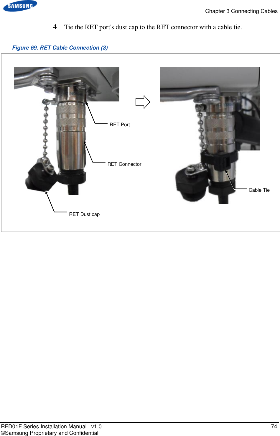
![Chapter 3 Connecting Cables RFD01F Series Installation Manual v1.0 72 © Samsung Proprietary and Confidential 2 Install an RET cable from the RF Antenna to the RRU RET port. Figure 67. RET Cable Connection (1) RET Cable Assembly [RF Antenna] [Bottom View]](https://usermanual.wiki/Samsung-Electronics-Co/RFD01F-26A.RFD01F-26A-User-Manual-Ver-1-1-Sprint-EN/User-Guide-3278855-Page-83.png)
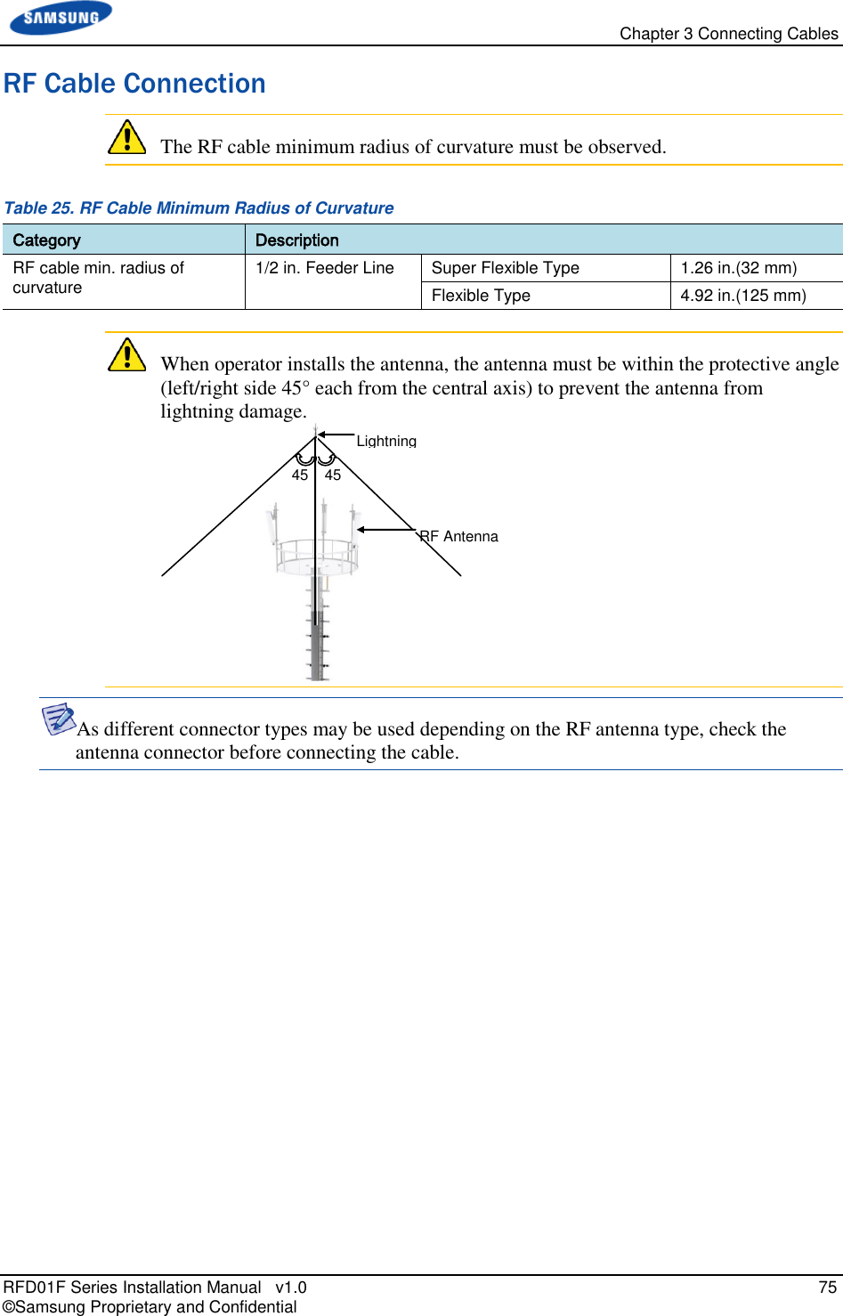
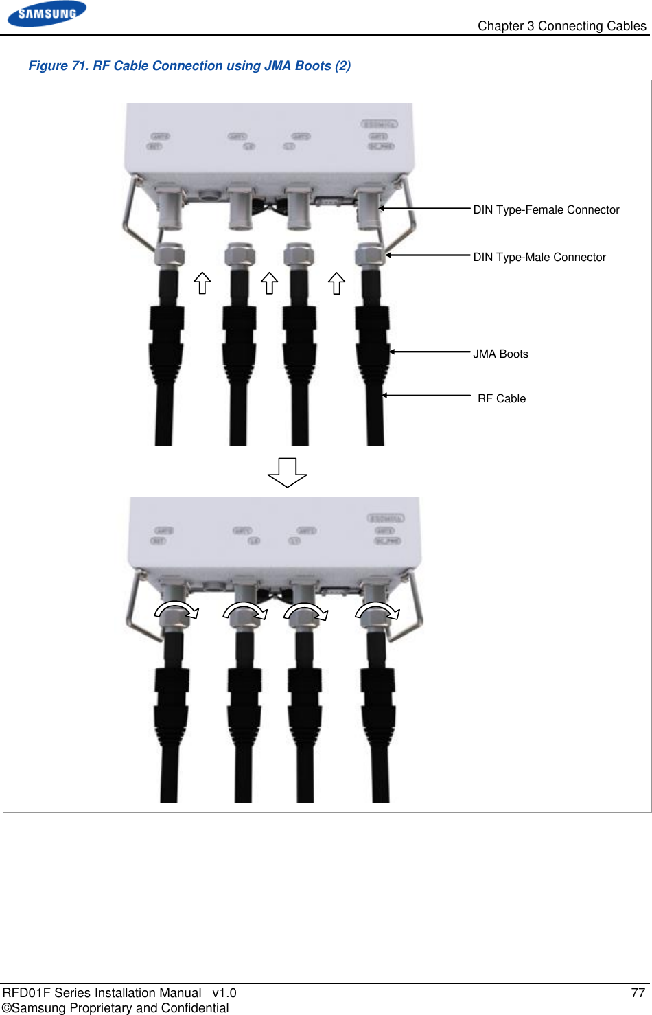
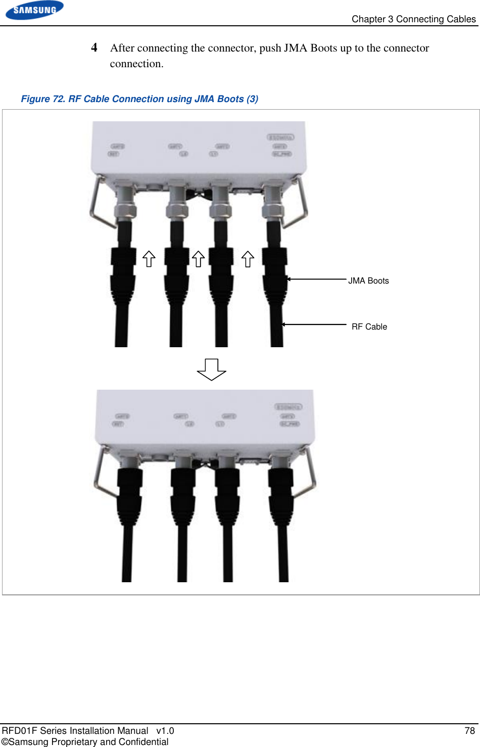
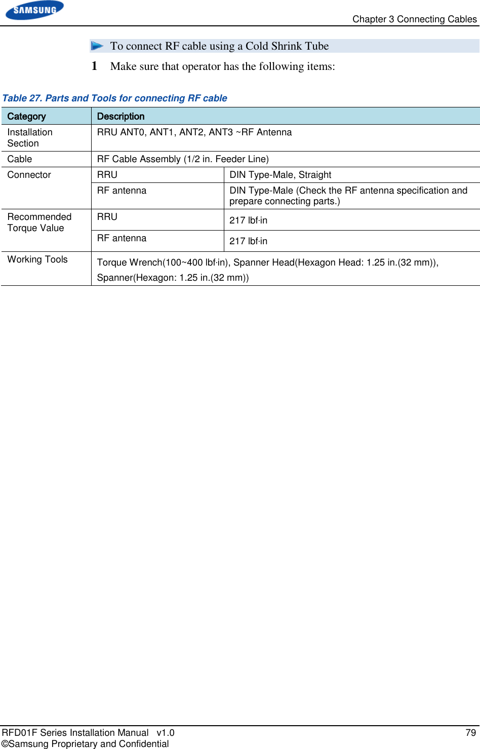
![Chapter 3 Connecting Cables RFD01F Series Installation Manual v1.0 76 © Samsung Proprietary and Confidential To connect RF cable using JMA Boots 1 Make sure that operator has the following items: Table 26. Parts and Tools for connecting RF cable Category Description Installation Section RRU ANT0, ANT1, ANT2, ANT3 ~RF Antenna Cable RF Cable Assembly (1/2 in. Feeder Line) Connector RRU DIN Type-Male, Straight RF antenna DIN Type-Male (Check the RF antenna specification and prepare connecting parts.) Recommended Torque Value RRU 217 lbf·in RF antenna 217 lbf·in Working Tools Torque Wrench(100~400 lbf·in), Spanner Head(Hexagon Head: 1.25 in.(32 mm)), Spanner(Hexagon: 1.25 in.(32 mm)) 2 Install RF cable assembly from the RRU ANT0, ANT1, ANT2, ANT3 ports to the RF antenna. (There are JMA boots on both sides of the RF cable assembly.) Figure 70. RF Cable Connection using JMA Boots (1) 3 Connect the connector assembled at the end of RRU side’s cable to the ANT_0, ANT_1, ANT_2, ANT_3 ports. RF Cable Assembly [RF Antenna] [Bottom View]](https://usermanual.wiki/Samsung-Electronics-Co/RFD01F-26A.RFD01F-26A-User-Manual-Ver-1-1-Sprint-EN/User-Guide-3278855-Page-87.png)
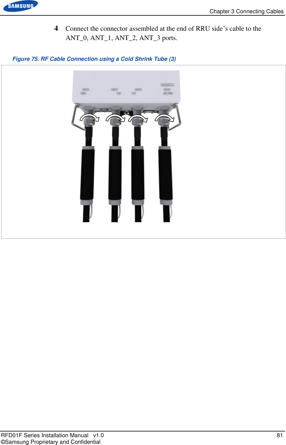
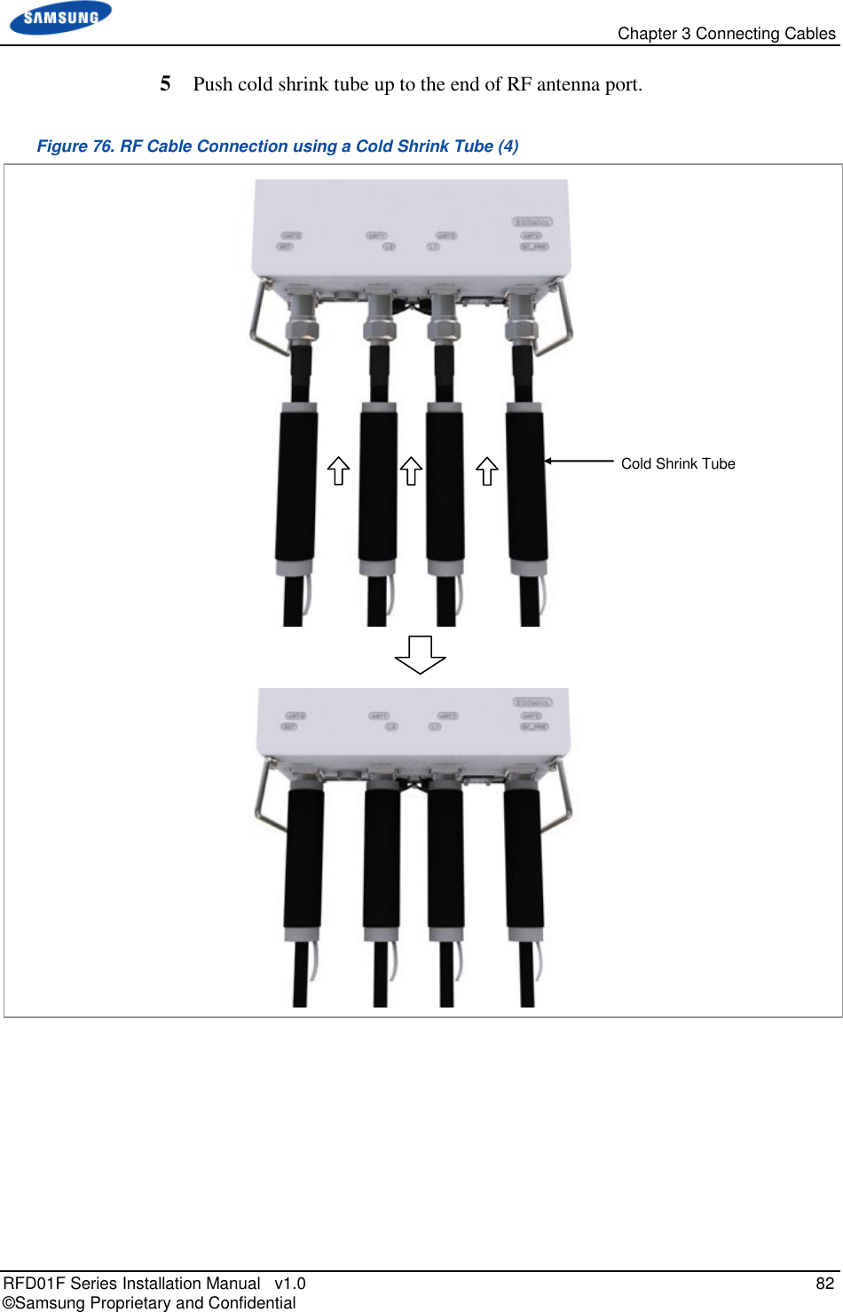
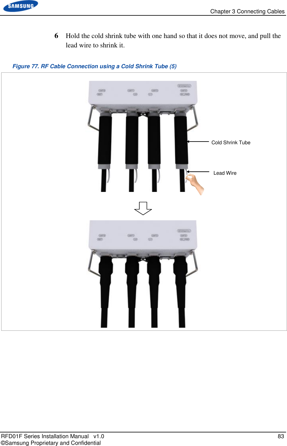
![Chapter 3 Connecting Cables RFD01F Series Installation Manual v1.0 80 © Samsung Proprietary and Confidential 2 Install RF cable assembly from the RRU ANT0, ANT1, ANT2, ANT3 ports to the RF antenna. Figure 73. RF Cable Connection using a Cold Shrink Tube (1) 3 Insert cold shrink tube to the end of RRU side’s cable. Figure 74. RF Cable Connection using a Cold Shrink Tube (2) RF Cable DIN Type-Female Connector DIN Type-Male Connector Cold Shrink Tube RF Cable [RF Antenna] [Bottom View]](https://usermanual.wiki/Samsung-Electronics-Co/RFD01F-26A.RFD01F-26A-User-Manual-Ver-1-1-Sprint-EN/User-Guide-3278855-Page-91.png)

![Chapter 4 Inspect the Installation RFD01F Series Installation Manual v1.0 93 © Samsung Proprietary and Confidential Measure the Optical Output and Connecting the Optical Connector To measure the optical output 1 Using an optical power meter check the optical output. 2 If the optical output measurement result meets the reference value, clean the connector again and connect it. 3 If the measurement result does not meet the reference value, discard the cable, replace it with a new cable, and then clean the new one and connect it to the system. [Optical Power meter] [LC/PC Plug]](https://usermanual.wiki/Samsung-Electronics-Co/RFD01F-26A.RFD01F-26A-User-Manual-Ver-1-1-Sprint-EN/User-Guide-3278855-Page-104.png)