Samsung Electronics Co RFV01U-D2A RRU (RFV01U) User Manual RFV01U D2A Rev 01 2
Samsung Electronics Co Ltd RRU (RFV01U) RFV01U D2A Rev 01 2
UserManual.wiki
>
Samsung Electronics Co
>
RFV01U-D2A User Manual
>
RFV01U-D2A_User Manual_Rev.01_2
Contents
1.
RFV01U-D2A_User Manual_Rev.01_1
2.
RFV01U-D2A_User Manual_Rev.01_2
RFV01U-D2A_User Manual_Rev.01_2
Navigation menu
Upload a User Manual
Namespaces
Wiki Guide
HTML
PDF
Info
Views
User Manual
Discussion / Help
Navigation
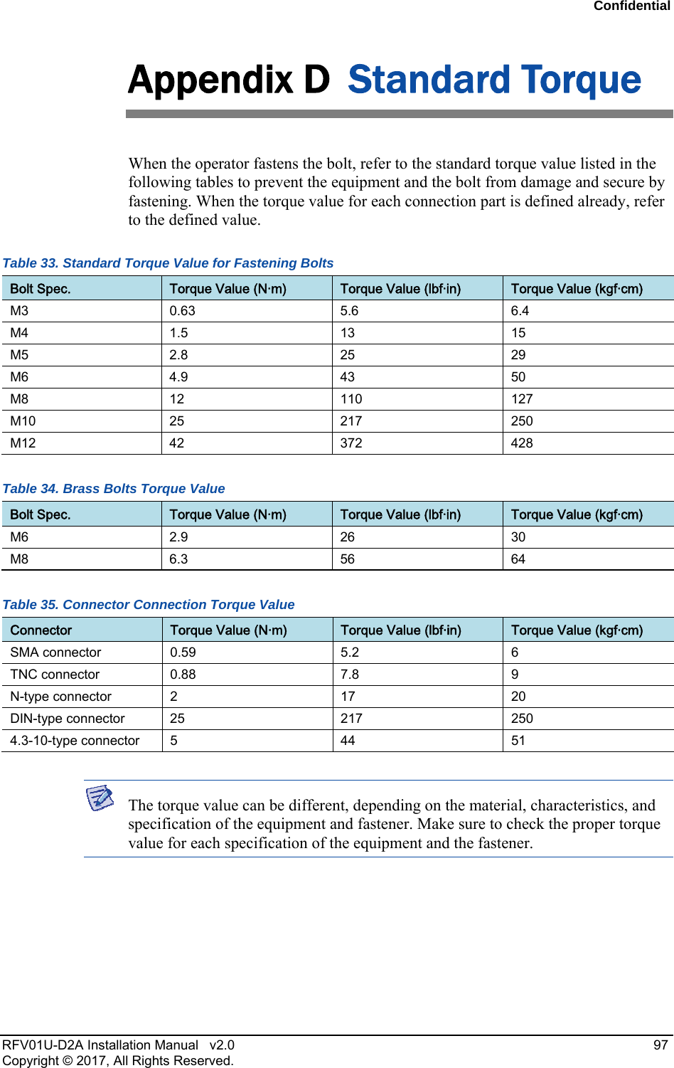
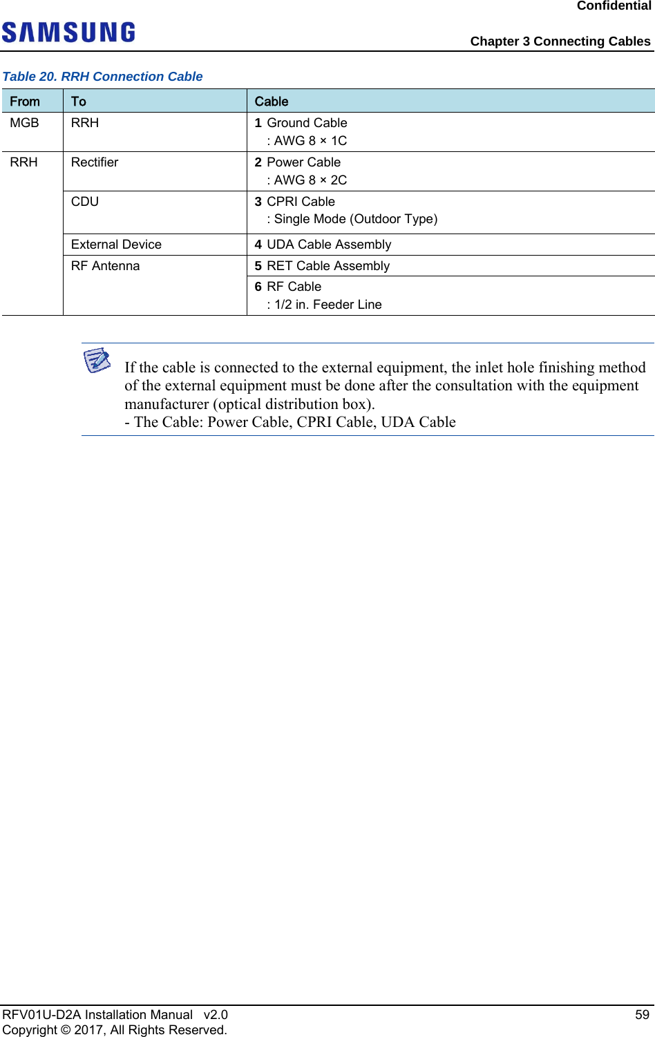
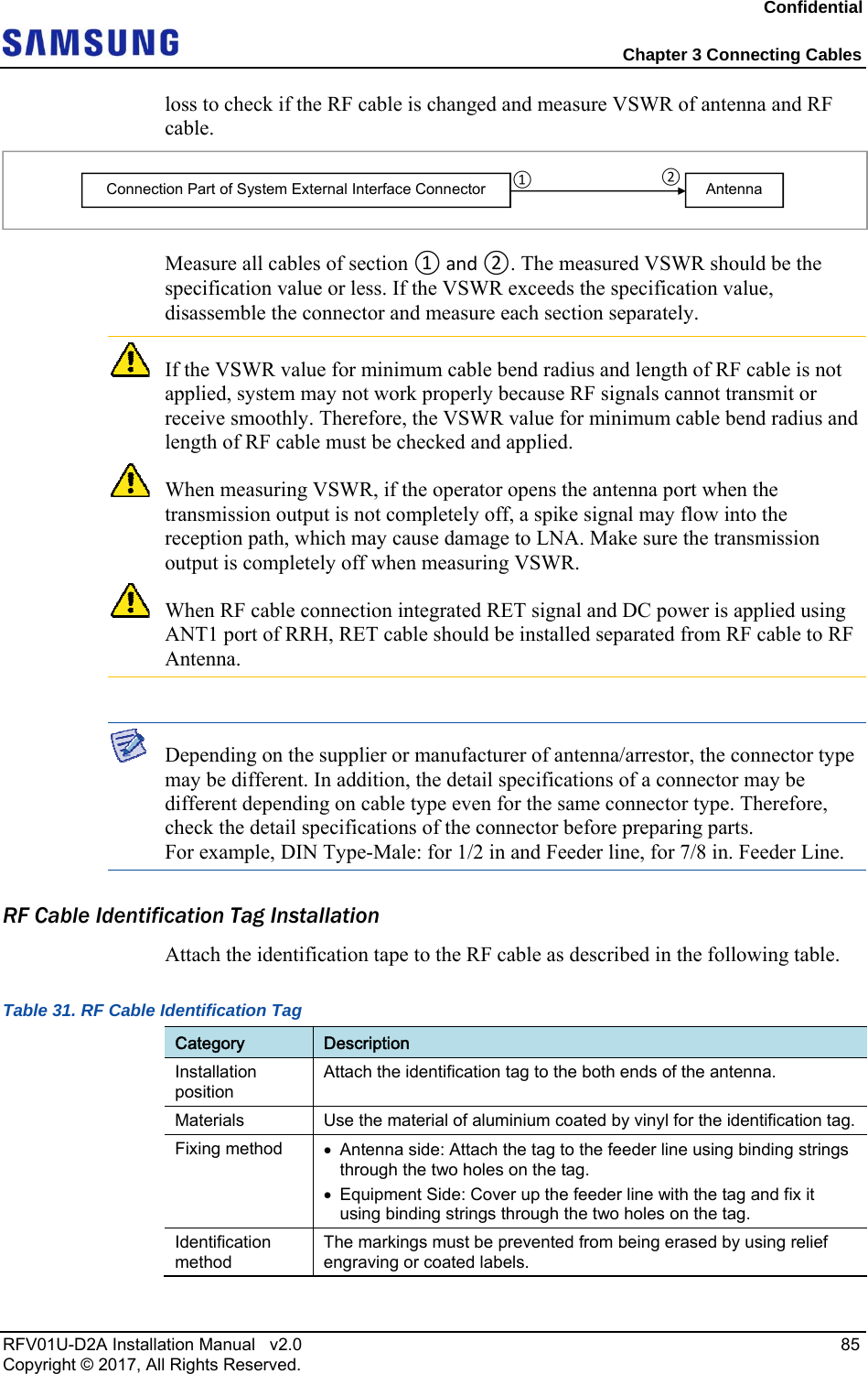
![Confidential Chapter 3 Connecting Cables RFV01U-D2A Installation Manual v2.0 58 Copyright © 2017, All Rights Reserved. Cabling Diagram The following figures depict the cabling connections of the RRH. Figure 54. Cable Diagram_RF Connection: 2T2R Figure 55. Cable Diagram_ RF Connection: 2T4R, 4T4R The following table details the RRH cable connections. RF Antenna Rectifier 6) RF Cable MGB External Device 1) Ground Cable 3) CPRI Cable 4) UDA Cable CDU 5) RET Cable 2) Power Cable [Bottom View]* When using the TMA, the RET cables are not connected. RF Antenna Rectifier 6) RF Cable MGB External Device 1) Ground Cable 3) CPRI Cable 4) UDA Cable CDU 5) RET Cable 2) Power Cable [Bottom View]](https://usermanual.wiki/Samsung-Electronics-Co/RFV01U-D2A.RFV01U-D2A-User-Manual-Rev-01-2/User-Guide-3499346-Page-6.png)
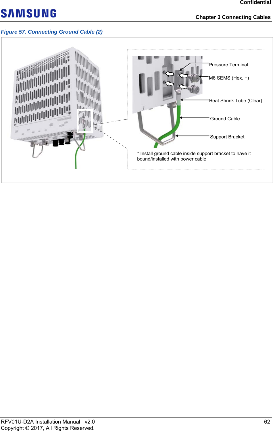
![Confidential Chapter 3 Connecting Cables RFV01U-D2A Installation Manual v2.0 61 Copyright © 2017, All Rights Reserved. Category Description Torque Value Working Tools Cable Cutter Wire Stripper Crimping tool Heating Gun Nipper Screw Driver (‘+’, No. 3) Torque Driver (20 to 90 lbf·in.) Screw Driver Bit (‘+’, No. 3) For the pressure terminal of the cable, the UL listed products or equivalent should be used. For example, Manufacturer-Panduit RRH: AWG8 Pressure Terminal (LCD8-14A-L) 2 Install the ground cable from the MGB to the RRH ground terminal. Figure 56. Connecting Ground Cable (1) 3 Assemble a pressure terminal and a heat shrink tube at the end of the RRH ground cable. 4 Align the pressure terminal to the mounting hole of the RRH ground terminal. 5 Fix the pressure terminal firmly onto the RRH ground terminal using fasteners. [Bottom View] MGB Ground Cable](https://usermanual.wiki/Samsung-Electronics-Co/RFV01U-D2A.RFV01U-D2A-User-Manual-Rev-01-2/User-Guide-3499346-Page-9.png)
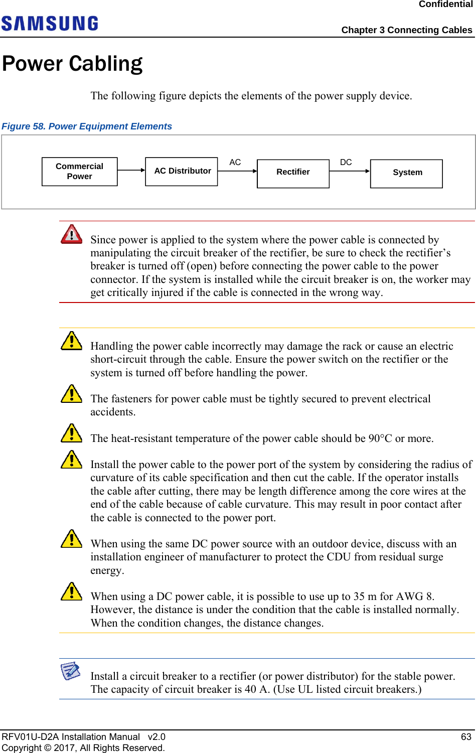
![Confidential Chapter 3 Connecting Cables RFV01U-D2A Installation Manual v2.0 64 Copyright © 2017, All Rights Reserved. Connecting Power Cable To connect the power cable, do the following: 1 Make sure you have the following items: Table 22. Parts and Tools for connecting Power Cable Category Description Installation Section Rectifier~RRH Power Input Port Cable AWG 8 × 2C (The color of the core wire can be changed according to the specification of the cable used.) Connector Rectifier Check specifications of rectifier output terminal per site and prepare fasteners. RRH JONHON Push Pull Type CT48J-1502TSCBM-07 to open Working Tools Cable Cutter Wire Stripper Compressor Heating Gun Nipper The following table describes the pin connectors of the power cable. Table 23. Power Cable/Connector Pin Map Power Connector Pin No. Description Color Pin 1 -48 V DC The color of the core wire can be changed according to the specification of the cable used. Pin 2 RTN 2 Install a DC power cable from the rectifier to the RRH. [Cable side Connector] [System side Connector] Bump GrooveBump GroovePin 1 Pin 2 Pin 1Pin 2](https://usermanual.wiki/Samsung-Electronics-Co/RFV01U-D2A.RFV01U-D2A-User-Manual-Rev-01-2/User-Guide-3499346-Page-12.png)
![Confidential Chapter 3 Connecting Cables RFV01U-D2A Installation Manual v2.0 65 Copyright © 2017, All Rights Reserved. Figure 59. Connecting Power Cable (1) 3 Insert the connector aligning to the white dot of the cable side connector and the system side connector, respectively. 4 When inserting the connector, push the shell to upper side. Figure 60. Connecting Power Cable (2) When the connector is fastened tight, the white line on the system side connector should be hidden. [Bottom View] Rectifier Power Cable System side connector’s white dot Cable side connector’s white dot Shell Push](https://usermanual.wiki/Samsung-Electronics-Co/RFV01U-D2A.RFV01U-D2A-User-Manual-Rev-01-2/User-Guide-3499346-Page-13.png)
![Confidential Chapter 3 Connecting Cables RFV01U-D2A Installation Manual v2.0 66 Copyright © 2017, All Rights Reserved. The method for connecting/disconnecting the power connector is as follows: - For connecting the connector, push the shell to upper side. - For disconnecting the connector, pull the coupling nut to lower side. White Line [White Line is invisible] [White Line is visible] ShellCoupling NutPush Pull](https://usermanual.wiki/Samsung-Electronics-Co/RFV01U-D2A.RFV01U-D2A-User-Manual-Rev-01-2/User-Guide-3499346-Page-14.png)
![Confidential Chapter 3 Connecting Cables RFV01U-D2A Installation Manual v2.0 67 Copyright © 2017, All Rights Reserved. Interface Cable Connection This section describes the procedures for connecting interface cables. Remove/Insert Optical Module If the optical module needs to be removed or inserted before connecting the cable, follow the process below. To remove the optical module, do the following: 1 Hang the hook of the Optical Transceiver Removal Tool on the bail of the optical module within the system. Figure 61. Optical Module Removal (1) 2 Remove the optical module completely from the transceiver by pulling the Optic Transceiver Removal Tool. Figure 62. Optical Module Removal (2) 3 Remove the optical module and the jig by pressing the hook grip of the Optical Transceiver Removal Tool. Figure 63. Optical Module Removal (3) To inset the optical module, do the following: Optical ConnectorOptical Module [System Inside] Optical TransceiverRemoval Tool’s HookBail [Front View]Location to hang the Optical Transceiver Removal Tool Optical Transceiver Removal Tool Optical ModuleTransceiver](https://usermanual.wiki/Samsung-Electronics-Co/RFV01U-D2A.RFV01U-D2A-User-Manual-Rev-01-2/User-Guide-3499346-Page-15.png)
![Confidential Chapter 3 Connecting Cables RFV01U-D2A Installation Manual v2.0 68 Copyright © 2017, All Rights Reserved. Push the optical module into the transceiver within the connector. Figure 64. Optical Module Inset Inset the bail of the optical module, facing the front of the system, to the port. Do not inset when the bail of the optic module is unlocked. Connecting CPRI Cable To connect the CPRI cable, do the following: 1 Make sure you have the following items: Table 24. Parts and Tools for connecting CPRI Cable Category Description Installation Section RRH L0 Port~CDU Cable CPRI Cable (Optical, Single Mode, for Outdoor Type) Connector RRH JONHON Push Pull Type PDLC03T03 (DLC/UPC) Working Tools Optical Connector Cleaner [System Inside] Transceiver Optical ModuleOptical Connector Optical Module Bail Optical Module Bail[Raised: Lock] [Lowered: Unlock]](https://usermanual.wiki/Samsung-Electronics-Co/RFV01U-D2A.RFV01U-D2A-User-Manual-Rev-01-2/User-Guide-3499346-Page-16.png)
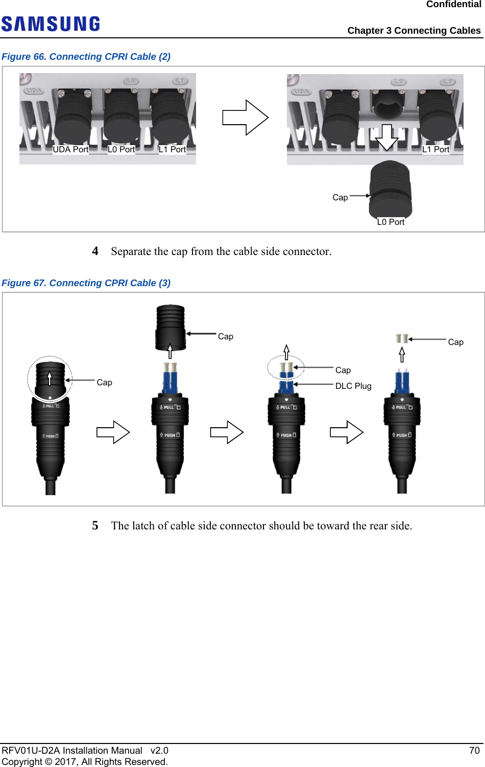
![Confidential Chapter 3 Connecting Cables RFV01U-D2A Installation Manual v2.0 69 Copyright © 2017, All Rights Reserved. In the system, the laser beam light runs through the optical cable. Handle the cable carefully because the exposure of the laser beam on worker’s eye may cause serious injury. Remove the cap of the optical connector before connecting. - Before connecting the optical cable, check if the ferrule of the connector is soiled. Be careful to keep the cutting section away from dust or foreign material. If the cable is soiled with foreign material, do not blow to remove them. - Make sure to clean the connector in accordance with the cleaning directions in Annex. - Do not touch the ferrule at the end of optical cable because it is easy to be damaged. Do not remove the cap of unused L1 port when installing since the CPRI cable is connected to the L0 port only. 2 Install the CPRI cable from the RRH (L0 port) to the CDU. Figure 65. Connecting CPRI Cable (1) 3 Separate the cap from the system side connector (L0 port). Ferrule[Before Removing Cap] [After Removing Cap] Cap[L1 Port][L0 Port]Not UsingUsing [Bottom View] CPRI Cable CDU](https://usermanual.wiki/Samsung-Electronics-Co/RFV01U-D2A.RFV01U-D2A-User-Manual-Rev-01-2/User-Guide-3499346-Page-17.png)
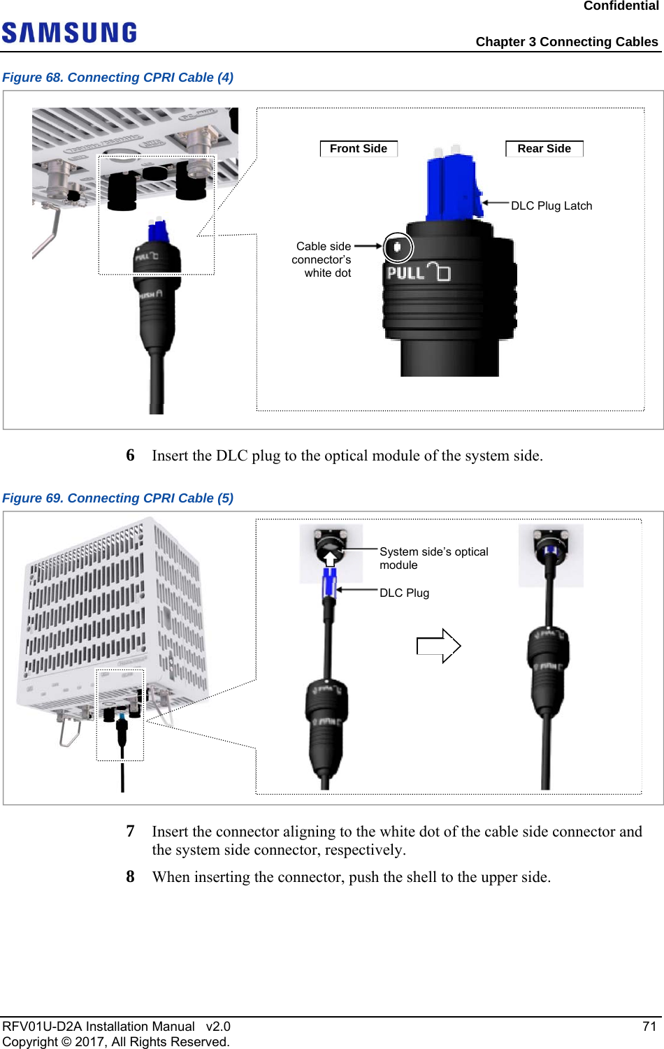
![Confidential Chapter 3 Connecting Cables RFV01U-D2A Installation Manual v2.0 72 Copyright © 2017, All Rights Reserved. Figure 70. Connecting CPRI Cable (6) When the connector is fastened tight, the white line on the system side connector should be hidden. The method for connecting/disconnecting the CPRI (optical) connector is as follows: - For connecting the connector, push the shell to upper side. - For disconnecting the connector, pull the coupling nut to lower side. Shell Push System side connector’s white dot Cable side connector’s white dot White Line [White Line is invisible] [White Line is visible]](https://usermanual.wiki/Samsung-Electronics-Co/RFV01U-D2A.RFV01U-D2A-User-Manual-Rev-01-2/User-Guide-3499346-Page-20.png)
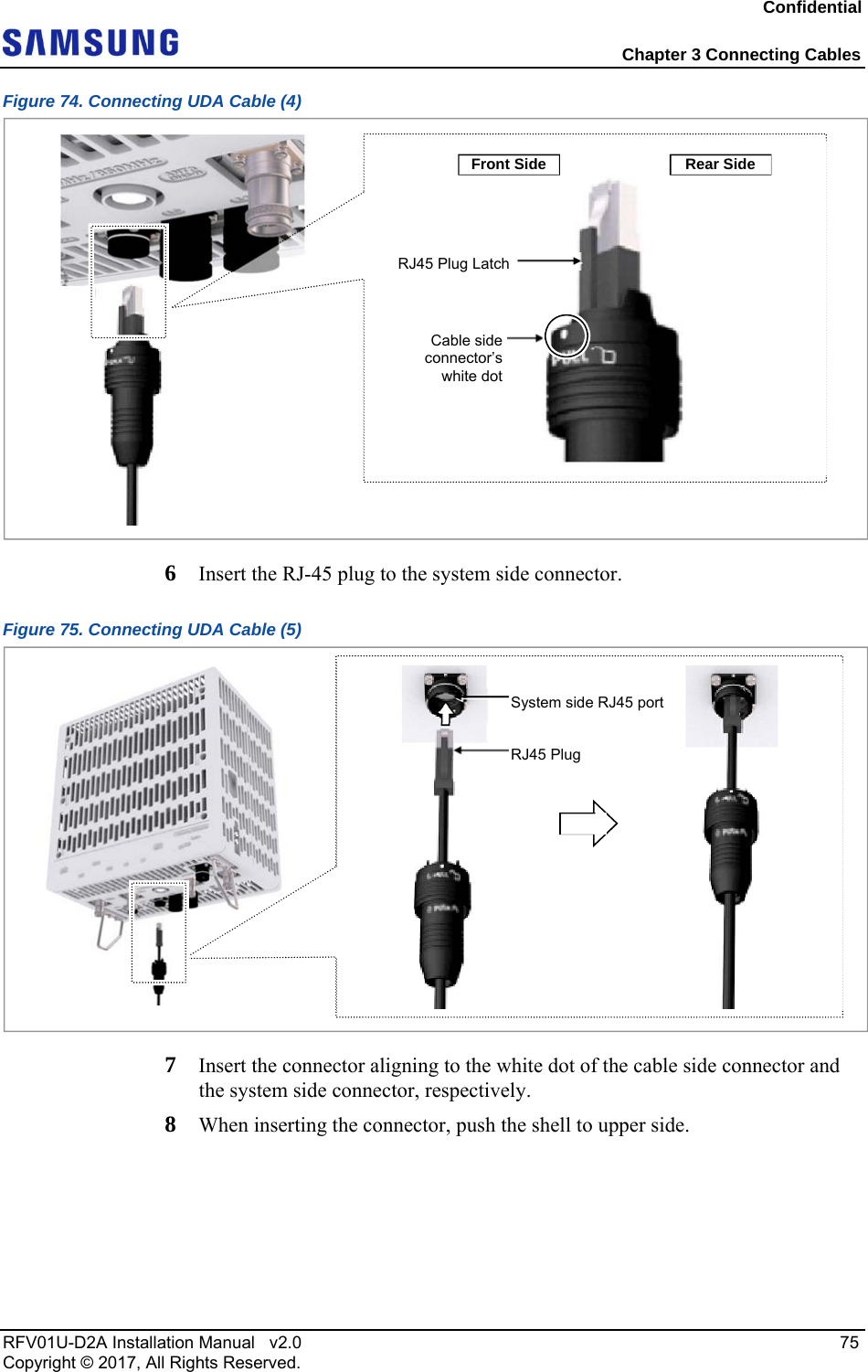
![Confidential Chapter 3 Connecting Cables RFV01U-D2A Installation Manual v2.0 74 Copyright © 2017, All Rights Reserved. Figure 71. Connecting UDA Cable (1) 3 Separate the cap from the system side connector (UDA port). Figure 72. Connecting UDA Cable (2) 4 Separate the cap from the cable side connector. Figure 73. Connecting UDA Cable (3) 5 The latch of cable side connector should be toward the front of the system. [Bottom View] UDA Cable External Device Cap L0 Port L1 PortUDA Port Cap Cap](https://usermanual.wiki/Samsung-Electronics-Co/RFV01U-D2A.RFV01U-D2A-User-Manual-Rev-01-2/User-Guide-3499346-Page-22.png)
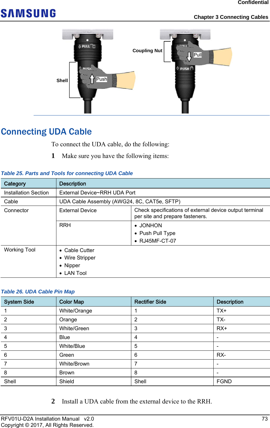
![Confidential Chapter 3 Connecting Cables RFV01U-D2A Installation Manual v2.0 76 Copyright © 2017, All Rights Reserved. Figure 76. Connecting UDA Cable (6) When the connector is fastened tight, the white line on the system side connector should be hidden. The method for connecting/disconnecting the UDA (RJ45) connector is as follows: - For connecting the connector, push the shell to upper side. - For disconnecting the connector, pull the coupling nut to lower side. System side connector’s white dot Cable side connector’s white dot Shell Push White Line [White Line is invisible] [White Line is visible]](https://usermanual.wiki/Samsung-Electronics-Co/RFV01U-D2A.RFV01U-D2A-User-Manual-Rev-01-2/User-Guide-3499346-Page-24.png)
![Confidential Chapter 3 Connecting Cables RFV01U-D2A Installation Manual v2.0 77 Copyright © 2017, All Rights Reserved. Connecting RET Cable To connect the RET cable, do the following: 1 Make sure you have the following items: Table 27. Parts for connecting RET Cable Category Description Installation Section RF Antenna~RRH RET port Cable RET Cable Assembly Connector RF Antenna Check the RF antenna (RETu) RET connector specification per site RRH AISG 2.2 Table 28. RET Cable Pin Map Pin No Description Cable Color 1 N/C (Not Connected) - 2 N/C (Not Connected) - 3 RS485 B White 4 GND Blue 5 RS485 A Brown 6 +24 V DC Red 7 DC Return Black 8 N/C (Not Connected) - [Male: RRH Side] [Female: Antenna Side]ShellCoupling NutPush Pull](https://usermanual.wiki/Samsung-Electronics-Co/RFV01U-D2A.RFV01U-D2A-User-Manual-Rev-01-2/User-Guide-3499346-Page-25.png)
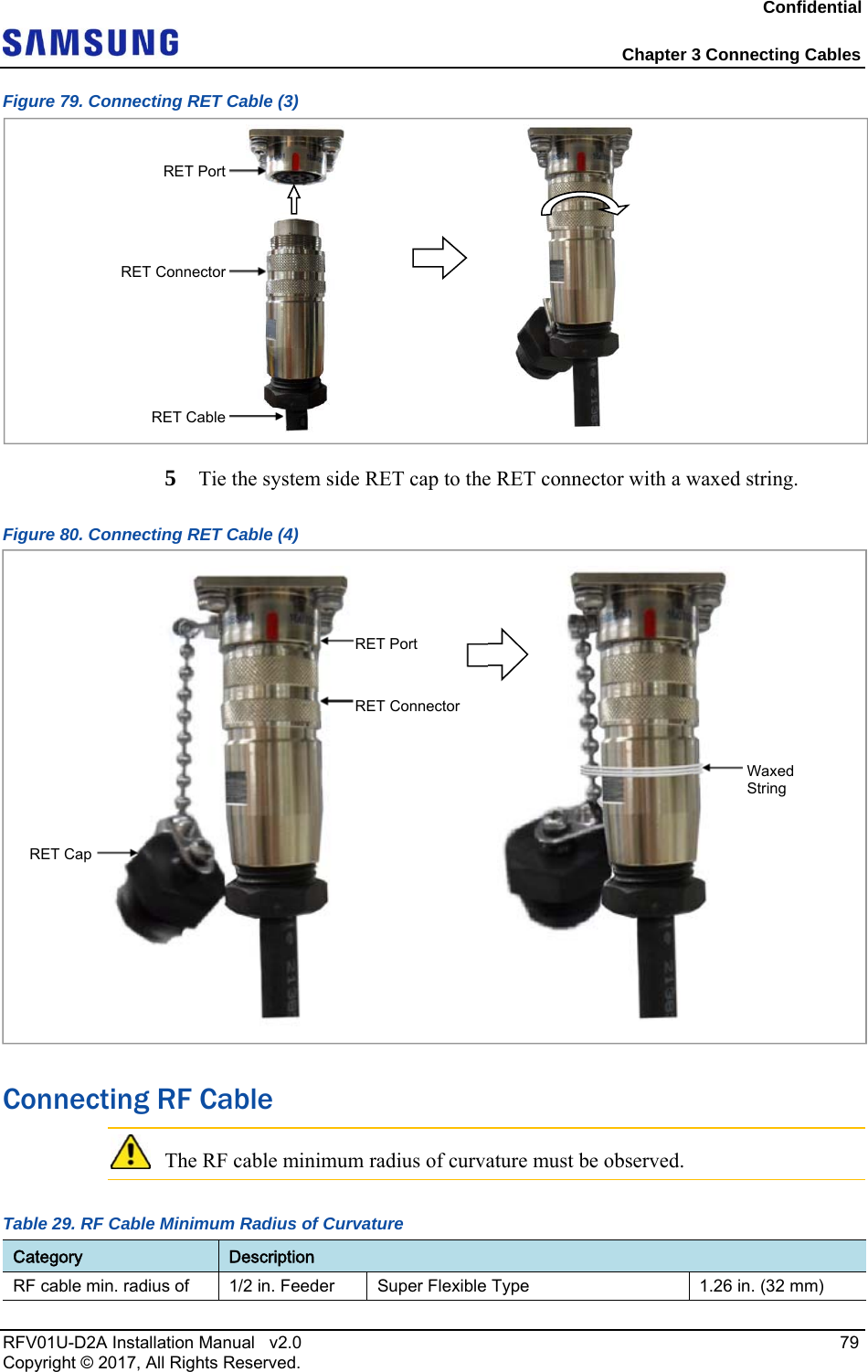
![Confidential Chapter 3 Connecting Cables RFV01U-D2A Installation Manual v2.0 78 Copyright © 2017, All Rights Reserved. Before fitting the RET connector, make sure to align the hole of the female connector to the pin of the male connector. 2 Install an RET cable from the RF antenna to the RRH RET port. Figure 77. Connecting RET Cable (1) 3 Separate the cap from the system side connector (RET port). Figure 78. Connecting RET Cable (2) 4 Connect the cable side RET connector to the system side RRH RET port. [Male Connector] [Female Connector] Hole Pin RF Antenna’s RET [Bottom View] RET Cable RET Cap RET Port RET Port (Female)](https://usermanual.wiki/Samsung-Electronics-Co/RFV01U-D2A.RFV01U-D2A-User-Manual-Rev-01-2/User-Guide-3499346-Page-26.png)
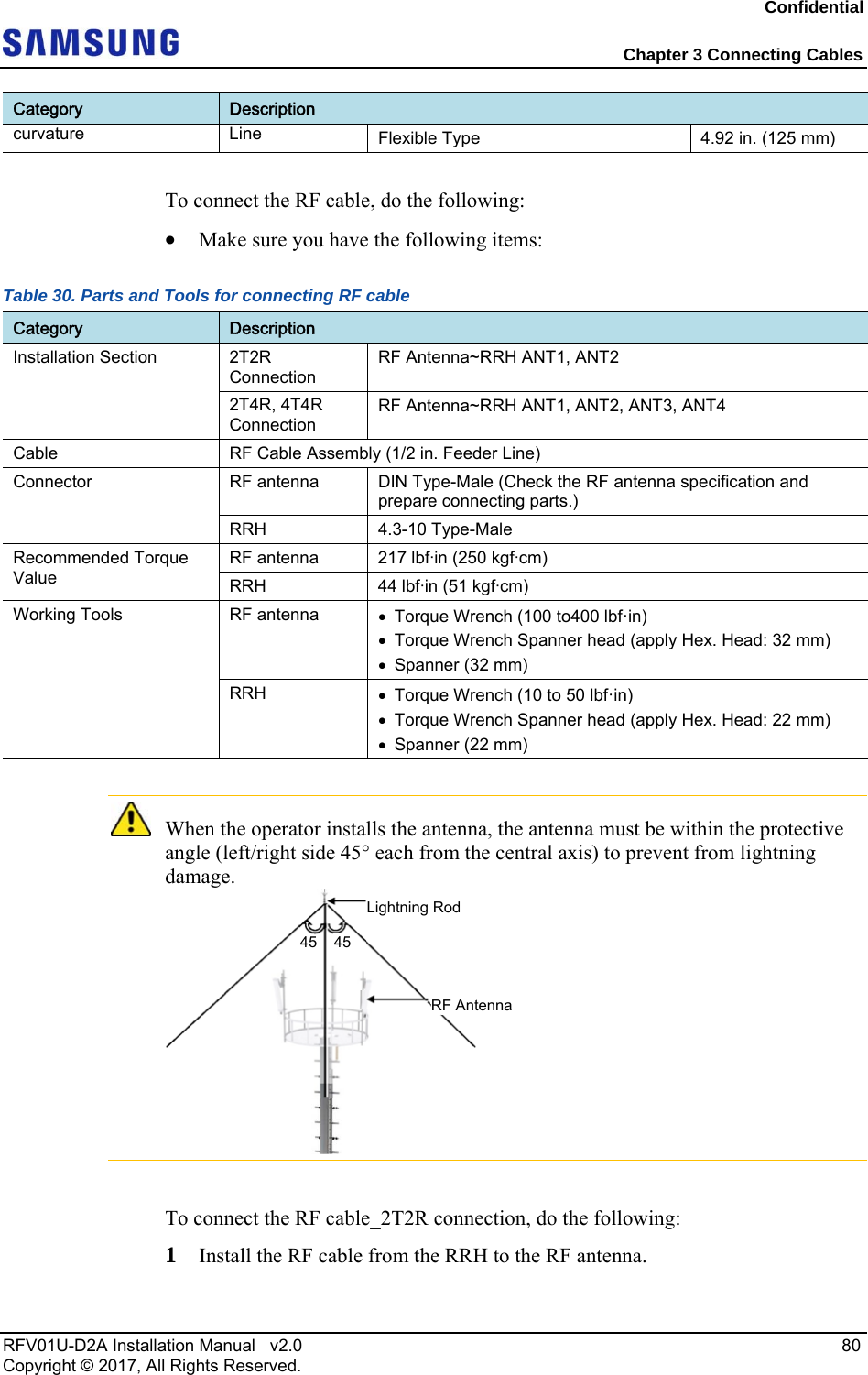
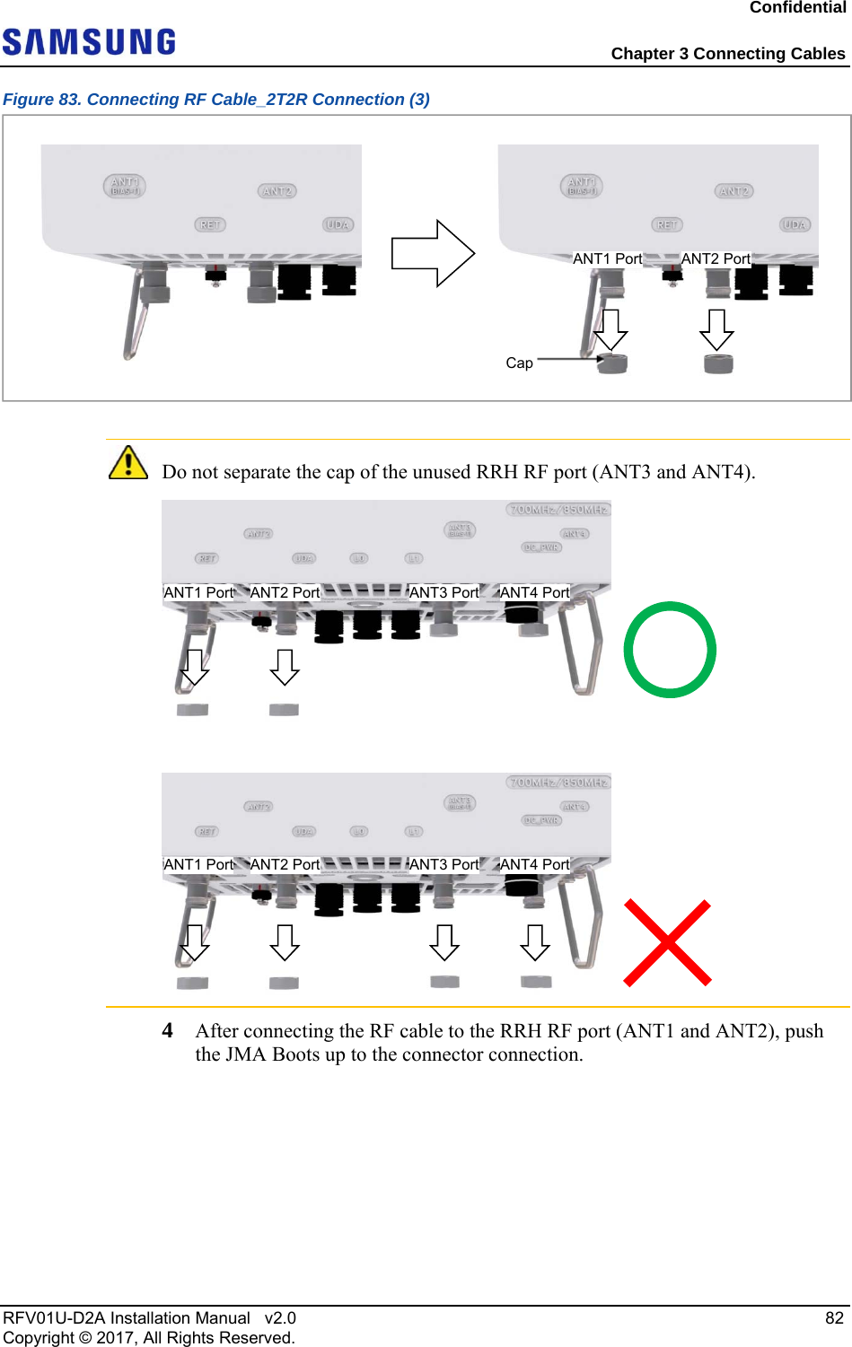
![Confidential Chapter 3 Connecting Cables RFV01U-D2A Installation Manual v2.0 81 Copyright © 2017, All Rights Reserved. Figure 81. Connecting RF Cable_2T2R Connection (1) 2 After connecting RF cable to the RF antenna port, push the JMA Boots up to the connector connection. Figure 82. Connecting RF Cable_2T2R Connection (2) As different connector types may be used depending on the RF antenna type, check the antenna connector before connecting the cable. 3 Separate the cap of the RRH RF port (ANT1 and ANT2). [Bottom View] RF Antenna RF Cable RF Cable (1/2 in. Feeder Line)JMA BootAntenna Port (Female) RF Connector (DIN Male)](https://usermanual.wiki/Samsung-Electronics-Co/RFV01U-D2A.RFV01U-D2A-User-Manual-Rev-01-2/User-Guide-3499346-Page-29.png)
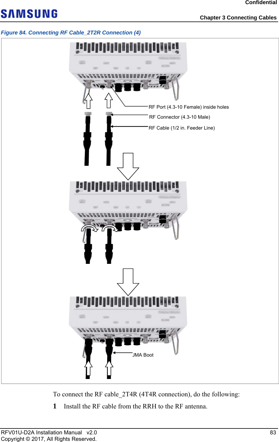
![Confidential Chapter 3 Connecting Cables RFV01U-D2A Installation Manual v2.0 84 Copyright © 2017, All Rights Reserved. Figure 85. Connecting RF Cable_2T4R, 4T4R Connection (1) 2 After connecting the RRH and RF antenna, take waterproof treatment using JMA boots (for more information, see ‘To connect the RF cable_2T2R connection’) Figure 86. Connecting RF Cable_2T4R, 4T4R Connection (2) Checking RF Cable Connection After connecting the RF cables, perform the continuity test and feeder cable return [Bottom View] RF Antenna RF Cable [RF Antenna side][RF Antenna][RRH side][RRH]](https://usermanual.wiki/Samsung-Electronics-Co/RFV01U-D2A.RFV01U-D2A-User-Manual-Rev-01-2/User-Guide-3499346-Page-32.png)
![Confidential Appendix C Clean the Optical Connectors RFV01U-D2A Installation Manual v2.0 96 Copyright © 2017, All Rights Reserved. 2 If the optical output measurement result meets the reference value, clean the connector again and connect it. 3 If the measurement result does not meet the reference value, discard the cable, replace it with a new cable, and then clean the new one and connect it to the system. [Optical Power meter] [LC/PC Plug]](https://usermanual.wiki/Samsung-Electronics-Co/RFV01U-D2A.RFV01U-D2A-User-Manual-Rev-01-2/User-Guide-3499346-Page-44.png)