Samsung Electronics Co S850 User Manual MANUAL
Samsung Electronics Co Ltd MANUAL
Contents
- 1. MANUAL
- 2. Manual
MANUAL

i
Notice
1998. All rights reserved
The information within this manual is subject to change without notice.
The manufacturer shall not be held liable for technical or editorial errors or
omissions contained herein; nor for incidental or consequential damages resulting
from the furnishing, performance or use of this material.
No part of this publication may be reproduced, stored in a retrieval system, or
transmitted, in any form or by any means, mechanical photocopying, recording or
otherwise, without the prior written permission of the manufacturer.
Product names mentioned herein are for identification purposes only, and may be
trademarks and/or registered trademarks of their respective companies.
This product incorporates copyright protection technology that is protected by
method claims of certain U.S. patents and other intellectual property rights
owned by Macrovision Corporation and other rights owners.
Use of this copyright protection technology must by authorized by Macrovision
Corporation, and is intended for home and other limited viewing uses only unless
otherwise authorized by Macrovision Corporation. Reverse engineering or
disassembly is prohibited.

ii
Important Safety Instruction
Read all of these instructions, and save these instructions for later use.
•Follow all warnings and instructions marked on the product.
•Unplug this product from the wall outlet before cleaning. Do not use liquid
cleaners or aerosol cleaners. Use a damp cloth for cleaning.
•Do not use this product near water. Never spill liquid of any kind on the
product.
•Do not place this product on an unstable cart, stand, or table.
•Slots and openings in the cabinet are provided for ventilation. To ensure
reliable operation of the product on a bed, sofa, rug, or other similar
surface. This product should never be placed near or over a radiator or
heat register. This product should not be placed in a built-in installation
unless proper ventilation is provided.
•Before connecting this product to a power source, check the required
voltage and frequency match the available power source.
•This computer is powered by an internal battery pack or by an external AC
power source, Which is supplied with the computer. Use of another
battery pack or AC power source may present risk of fire or explosion. To
disconnect the AC power cord and remove the battery packs.
•This product is equipped with a 2-wire type plug. If you are unable to insert
the plug into the outlet, contact your electrician to replace your obsolete
outlet.
•Do not allow anything to rest on the power cord.
•Do not place this product in a location where someone may trip over the
cord.
•If an extension cord is used with this product, make sure that the total of the
ampere ratings on the products plugged into the extension cord do not
exceed the extension cord ampere rating. Also, make sure that the total of
all products plugged into the wall outlet does not exceed 15 amperes.
•Never push objects of any kind into this product through the cabinet slots,
as they may touch dangerous voltage points or short out parts; that could
result in a risk of fire or electric shock.
•Except as explained elsewhere in this manual, do not attempt to service this
product yourself.
•Handle battery with care. If dropped, they may damaged.
•Do not allow the battery to be exposed to direct sunlight for extended
periods of time.

iii
•Do not attempt to disassemble the battery. If the battery is disassembled and
the electrodes are exposed to outside, the battery may generate eat and
smoke by chemical reaction.
•Do not expose the battery to moisture or chemicals.
•Charge the battery only as described in this document.
•Do not short circuit the battery terminals as the resulting high currents can
damage the battery.
•The battery should not be used to power other products.
•Do not dispose of a used battery in a fire or incinerator, as an explosion may
result.
•The battery should be recycled.
•Do not subject the battery to temperature should not less than -20 degrees
Centigrade or greater than 50 degrees Centigrade.
•Unplug this product from the wall outlet and refer problems to the service
representative under the following conditions:
- When the power cord or plug is damaged or frayed.
- If liquid has been spilled into product.
- If the product has been exposed to rain or water.
- If the product does not operate normally when the operating
instructions are followed, adjust only those controls that are
covered by the operating instructions. Improper adjustment of
other controls may result in damage.
- If the product exhibits a distinct change in performance.

iv
Battery Disposal
Warning : Do not put rechargeable batteries or products powered by non-
removable rechargeable batteries in the garbage.
Contact your customer service representative for information on how to dispose
of batteries that you cannot use or recharge any longer.
Follow all local regulations when old batteries.

v
Federal Communications Commission
(FCC)
This device complies with Part 15 of the FCC Rules. Operation is subject to the
following two conditions:(1) this device may not cause harmful interference, and
(2) this device must accept any interference received, including interference that
may cause undesired operation.
NOTE:
This equipment has been tested and found to comply with the limits for a Class B
digital device pursuant to Part 15 of the FCC Rules. These limits are designed to
provide reasonable protection against harmful interference in a residential
installation. This equipment generate uses and can radiate radio frequency energy
and if not installed and used in accordance with the instructions may cause
harmful interference will not occur in a particular installation. If this equipment
does cause harmful interference to radio or television reception, which can be
determined by turning the equipment off and on, the user is encouraged to try to
correct the interference by one or more of the following measures:
•Reorient or relocate the receiving antenna.
•Increase the separation between the equipment and receiver.
•Connect the equipment into an outlet on a circuit different from that to
which the receiver is connected.
•Consult the dealer or an experienced radio/TV technician for help.
If necessary, the user should consult the dealer or an experienced radio/television
technician for additional suggestions. The user may find the following booklet
helpful: "Something About Interference." This is available at FCC local regional
offices. Our company is not responsible for any radio or television interference
caused by unauthorized modifications of this equipment or the substitution or
attachment of connecting cables and equipment other than those specified by our
company. The correction will be the responsibility of the user. Use only shielded
data cables with this system.

vi
Canadian Radio Interference
Regulations
This apparatus does not exceed the class B limits for radio noise emissions set out
in the radio interference regulations of the Canadian Department of
Communications.
Le présent appareil n’émet pas de bruits radioélectriques dépassant les limites
applicable aux appareils de la classe B prescrites par le règlement de brouillage
radioélectrique dicté par le Ministère des Communictions du Canada.
Introducing Your Computer 3
Introducing Your Computer
Your computer is a lightweight portable computer that includes features to meet
your computing needs at home or on the road.
Your computer is one of 3-spindle type computer and 2-spindle type computer.
These computers are basically same, but the device arrangement is different.
•3-spindle type computer has CD-ROM drive and floppy drive within the
computer.
•2-spindle type computer has CD-ROM drive and external floppy disk drive
with its connectable cable. And different Status lights position from 3-spindle
type computer.
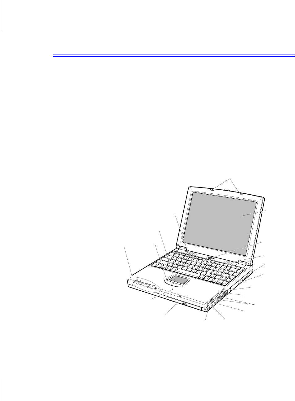
Figure 1 through 4 show you the features of your computer.
Figure 1. Front View of Computer (3-spindle type computer)
Cover latch
LCD
Power button
Fan vent
Headphone
jack
Touchpad
Speaker
Status
lights
Floppy drive
Microphone
External-mic jack
CD-ROM drive
Modem jack
Speaker
Mouse
Buttons
Line-in
USB ports
Infrared port
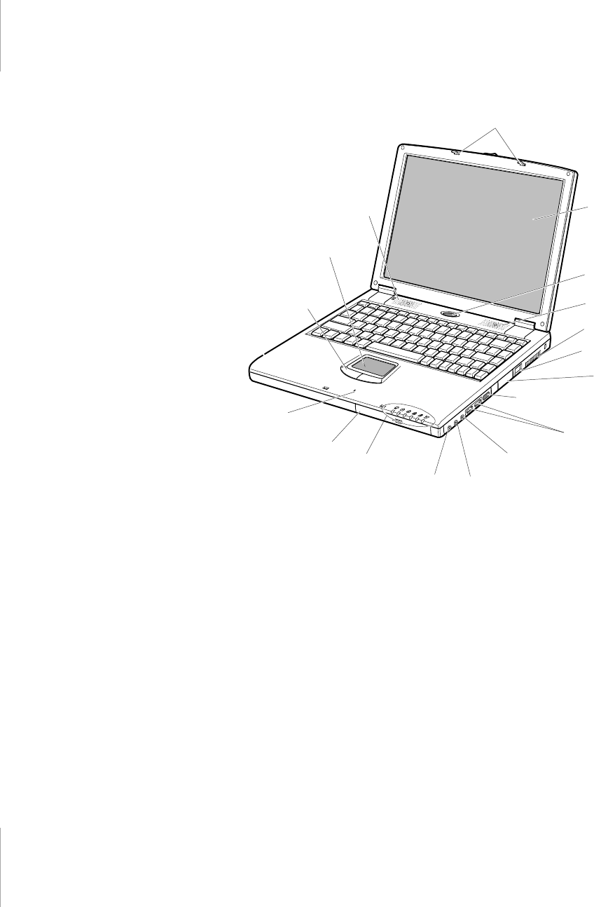
4 User’s Manual
Figure 2. Front View of Computer (2-spindle type computer)
Cover latch
LCD
Fan vent
Headphone
jack
Touchpad
Speaker
Status
lights
External
Floppy
Connectors
External-mic jack
CD-ROM drive
Modem jack
Speaker
Mouse
Buttons
Line-in
USB ports
Infrared port
Power button
Microphone
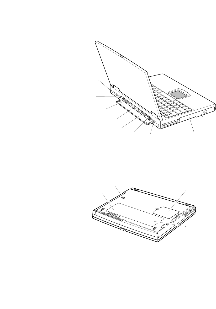
Introducing Your Computer 5
Figure 3. Back View of Computer
Figure 4. Bottom View of Computer
Parallel port
Docking
connector
PS/2™
mouse and
keyboard
port
Video port Serial
port
Hard drive
compartment
Power Connector
PC Card
compartment
Battery
compartment
TV out
Memory module
compartment
Label showing
part number and
serial number
Business card holder
Drive bay latch
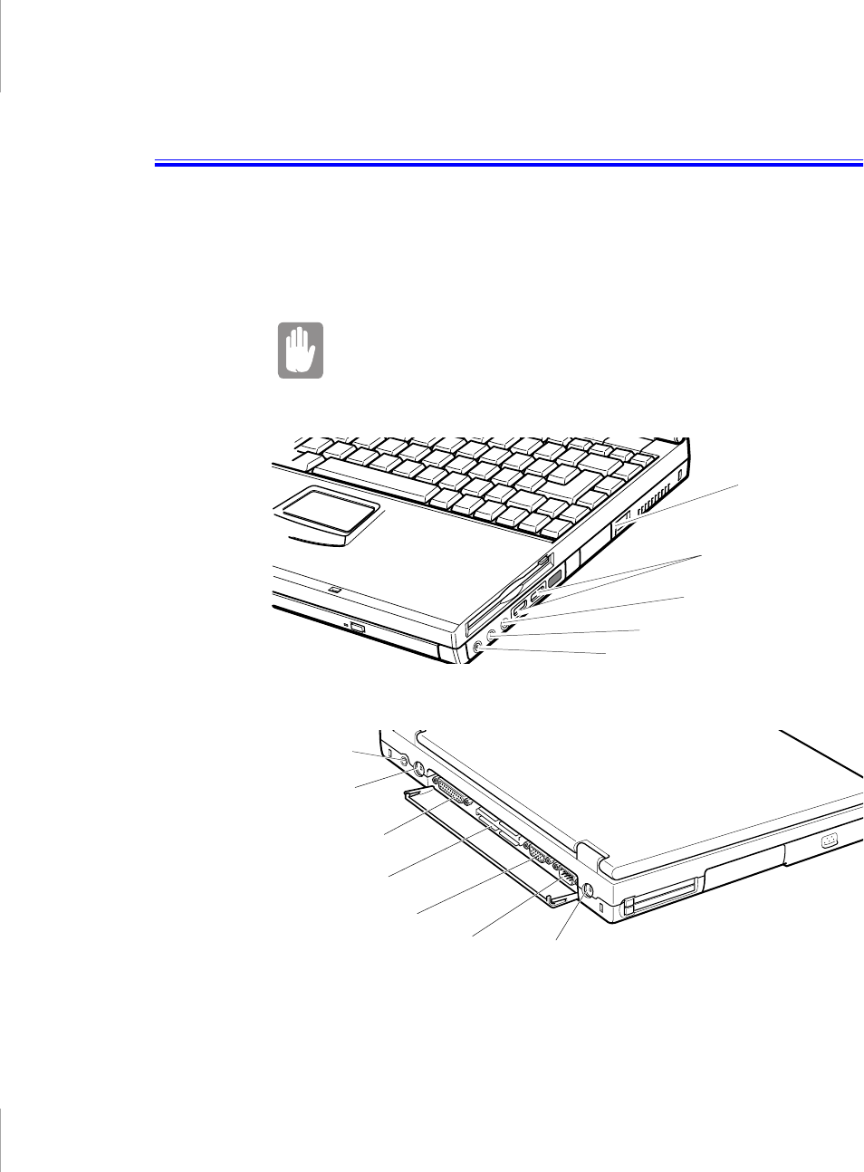
Connecting Peripheral Devices 21
Connecting Peripheral Devices
The connectors on your computer enable you to attach peripheral devices to the
computer (Figure 12). The system in Figure 12 is based on 3-spindle type
computer, 2-spindle type computer has no internal floppy disk drive, but external
floppy connectors instead.
Turn off your computer before you connect a peripheral
device. Connecting a peripheral device with your computer
turned on may seriously damage the device or your
computer.
Figure 12. Peripheral Connectors
PS/2 mouse and
keyboard port
Video port
Parallel port
USB ports
TV-out port (S-VHS)
Modem
jack
Mic-in jack
Headphone jack
Docking connector
Power
connector
Serial port
Line-in jack
22 User’s Manual
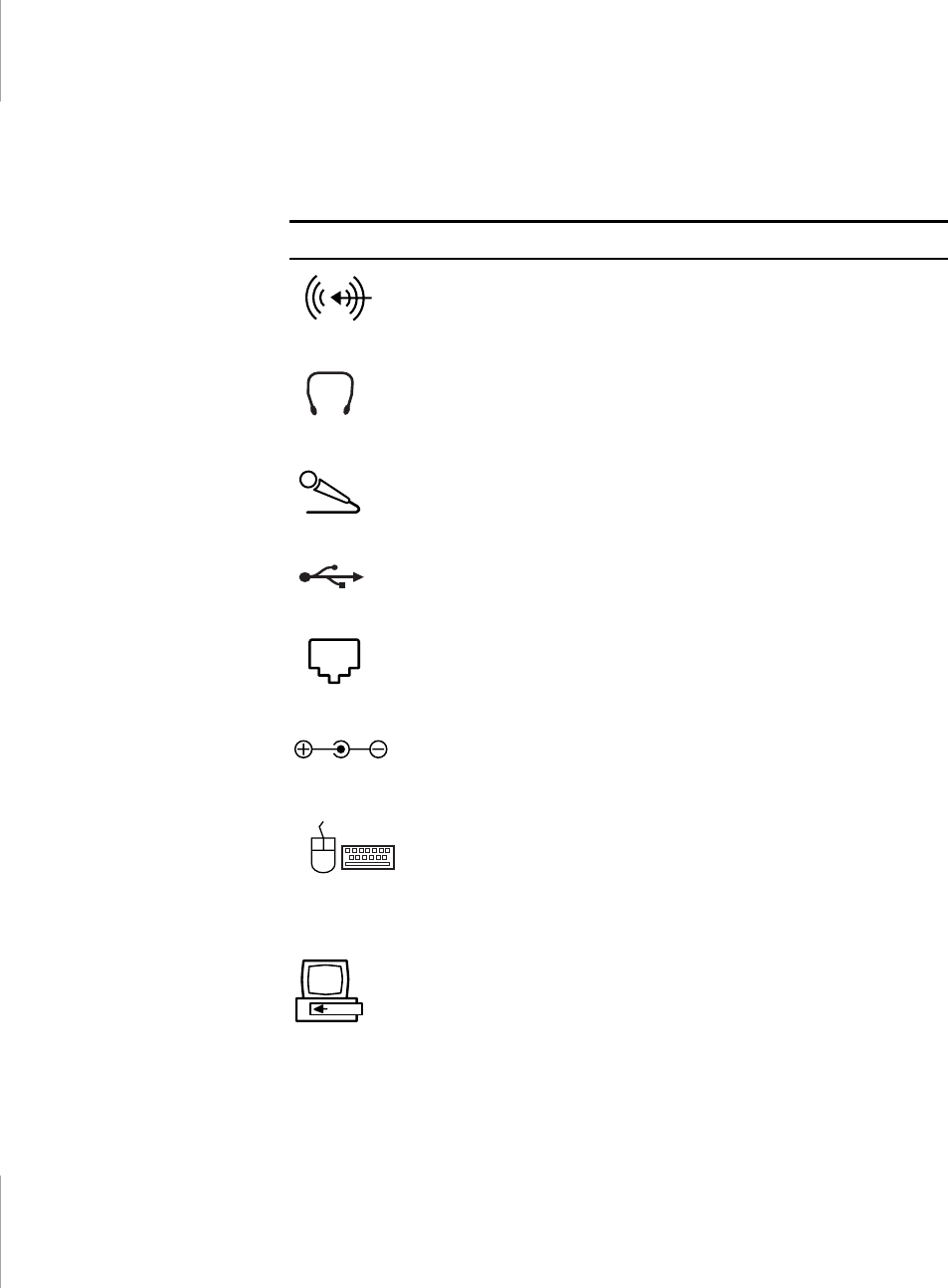
Table 4 shows the icons located near each connector and tells you the devices that
you can attach to the connectors.
Table 4. Connecting Peripheral Devices
Icon Connector
Line-in jack:
An input for external audio.
Headphone jack :
Connect stereo headphones or speakers to this
jack. Speakers connected to this jack override the internal
speakers.
Microphone jack :
Connect an external microphone to this jack.
USB (universal serial bus) port:
Connect USB devices to this port.
USB input/output devices include keyboards, pointing devices, and
monitors.
Modem jack:
Connect telephone line to connect to internet.
Power cord connector:
Plug in the power cord to run the computer
and charge the battery.
PS/2 (Personal System/2) mouse and keyboard port:
Connect a
PS/2-compatible mouse or external keyboard or keypad to this
port. Make sure your computer is turned off when you attach
peripherals to the port.
You can use the computer’s touchpad and a PS/2 keyboard at the
same time.
Docking connector:
Connect a docking option to this connector.
Connecting Peripheral Devices 23
If your computer’s operating system is Windows 98, you can enable and use the
USB port. The Windows NT 4.0 operating system does not support USB.
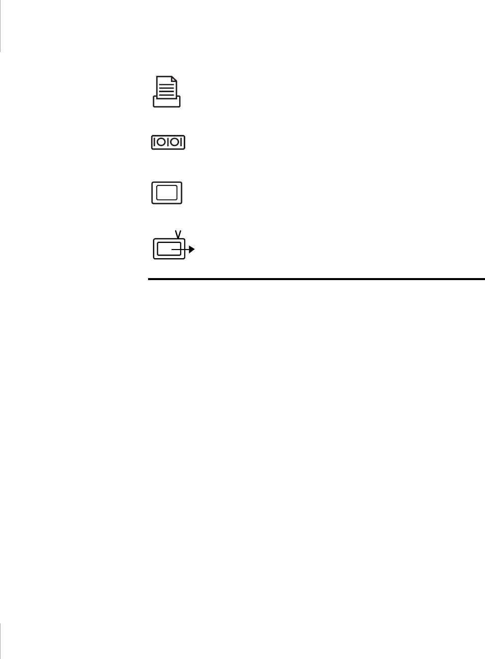
Parallel port:
Plug a parallel device, such as a parallel printer or
network adapter, into this 25-pin port.
Serial port:
Plug a serial device, such as a serial mouse, into this 9-
pin port. If the device has a 25-pin connector, you need a 25-to-9-
pin serial adapter.
Video port:
Plug the interface cable of an external monitor into this
15-pin connector and then plug the monitor power cord into a
grounded outlet.
TV-out port:
plug a S-VHS jack into this port and the other side of
the jack into an external TV. No audio is transmitted via this port.

Changing the Video Configuration 65
Changing the Video Configuration
Your computer includes a TFT LCD or active-matrix display. The capabilities of
the screen plus the video drivers installed on the computer determine the quality of
the image your LCD can display.
The following sections describe the display capabilities of your computer.
Resolution and Color Depth
The resolution of the LCD is the sharpness of the image it can display. Resolution
is measured by the number of pixels (individual dots) displayed on the entire
screen. In general, the more pixels the LCD can display, the better the image.
Your LCD screen is either SVGA or XGA:
•The maximum display for the SVGA LCD screen is 800x600, about 480,000
pixels.
•The maximum display for the XGA LCD screen is 1024x768, about 800,000
pixels.
The number of colors the LCD can display is measured by how many bits the LCD
uses to represent each pixel:
•8-bit color can support 256 different colors.
•16-bit color can support 64 K (65,536) colors.
•24-bit color can support 16 M (16.8 million) colors.
•32-bit color can support 16 M (16.8 million) colors.
24-bit color uses the RGB color model.
32-bit color uses the CMYK color model which gives better printed color
matching.
Table 8 lists the basic video mode capabilities and maximum colors supported by
your computer.

66 User’s Manual
Table 8. Video Driver Capabilities
All these video modes can be displayed on an external monitor. However, if you
disconnect an external monitor that was attached to your computer and then start
the computer, the LCD may revert to a different resolution than the one you chose
for the external monitor.
Configuring Display Features
The following sections describe how to configure the display settings on your
computer.
Selecting a Monitor Type
When you attach an external monitor to your computer, Windows 98 automatically
selects display settings for it (this feature is not available in Windows NT). If you
wish, you can adjust the display settings by selecting a monitor type:
1. Click the Start button on the Windows 98 taskbar.
Software
Drivers Resolution Supported with 4MB(8MB) GRAM Number of
Colors
Windows 98 640x480, 720x480, 800x600, 848x480, 1024x768,
1152x864, 1280x1024, 1600x1200 256
640x480, 720x480, 800x600, 848x480, 1024x768,
1152x864, 1280x1024, 1600x1200 65,536
640x480, 720x480, 800x600, 848x480, 1024x768,
1152x864, 1280x1024, (1600x1200)
16.8 million
(24 bit)
640x480, 720x480, 800x600, 848x480, 1024x768,
1152x864, (1280x1024) 16.8 million
(32 bit)
Windows
NT® 4.0 640x480, 800x600, 1024x768, 1152x864,
1280x1024, 1600x1200 256
640x480, 800x600, 1024x768, 1152x864,
1280x1024, 1600x1200 65,536
640x480, 800x600, 1024x768, 1152x864,
1280x1024, (1600x1200)
16.8 million
(24 bit)
640x480, 800x600, 1024x768, 1152x864,
(1280x1024)
16.8 million
(32 bit)

Changing the Video Configuration 67
2. Select Settings.
3. Click Control Panel. The Control Panel window appears.
4. Double-click the Display icon. The Display Properties window appears.
5. Click the Settings tab. The Settings screen appears.
6. Click the Advanced button. The Advanced Properties screen appears.
7. Click the Monitor tab.
8. Click the Change button. The Update Device Driver Wizard screen appears.
9. Click the Next button.
10. Select the Display a list of all the drivers in a specific location radio button and
click the Next button.
11. Select the Show all hardware radio button.
12. Select a manufacturer and model setting that matches your external monitor.
Your computer has an intelligent video chip set that automatically matches
your LCD panel resolution and frequency when an external monitor is not
present.
13. Click the Next button.
14. The Update Device Driver Wizard screen appears showing the driver location
of the device you have selected. Click the Next button.
15. Follow any prompts that appear on the screen.
Changing Color Depth and Resolution
To change the color depth and resolution of your LCD or external monitor:
1. Click the Start button on the Windows taskbar.
2. Select Settings.
3. Click Control Panel. The Control Panel window appears.
4. Double-click the Display icon. The Display Properties window appears.
5. Click the Settings tab. The Settings screen appears.
6. To change the color depth, click the arrow next to Color palette and select the
color depth you want.

68 User’s Manual
7. To change the resolution, click and drag the knob under the Screen area until
you select the resolution you want.
8. Click the OK button.
9. Follow the prompts that appear on the screen.
Changing the Video Driver
It is possible that you may want to update your video driver or that your installed
video driver has become corrupt so that the display is unusable.
In Windows 98:
1. Click on the Start Button. The Start Menu appears.
2. Select Settings and click on Control Panel, double click on Display. The
Display Properties window appears.
3. Click the Advanced button. The properties screen for your currently installed
video driver appears
4. Select the Adapter menu.
5. Click the Change button. The Update Device Driver Wizard window appears.
6. Click the Next button.
7. Select Display a list of all the drivers in a specific location, so you can select
the driver you want. Click the Next button.
8. Click the Have disk button. If the driver is on a floppy disk insert it into the
floppy drive or if you want to use the origianl factory driver insert the Restore
CD-ROM into the CD-ROM drive. Click the Browse button and locate driver
you want to install. Click the OK button.
9. Select the new driver in the Select Device screen and click the Ok button.
10. Click the Next button to install the new driver and follow any directions on the
screen to finish setting the display properties.
In Windows NT 4.0:
1. As the computer starts, select Windows NT Workstation Version 4.00 [VGA
mode] as the operating system and press <Enter>.

Changing the Video Configuration 69
2. Log on to the computer as supervisor. The Invalid Display Settings window
appears.
3. Click the OK button. The Display Properties window appears.
If the Change Display window appears, go to step 6.
4. Select the Settings menu.
5. Click the Display Type button. The Display Type window appears.
6. Click the Change button. The Change Display window appears.
7. Click the Have disk button. If the driver is on a floppy disk insert it into the
floppy drive or if you want to use the origianl factory driver insert the Restore
CD-ROM into the CD-ROM drive. Click the Browse button and locate driver
you want to install. Click the OK button.
8. A line similar to the following line appears under the Display option: ATI
Technologies Inc. 3D Rage LT Pro.
9. Click OK. The Third-Party Driver window appears.
10. Click Yes. The driver is copied. A window appears telling you the driver has
been successfully copied.
11. Click OK. Remove the disk from the floppy drive. Close the open windows on
the screen.
12. Click Yes when prompted to restart the computer. As the computer restarts,
select Windows NT Workstation Version 4.00 as the operating system and press
<Enter>.
13. Log on as supervisor. The Invalid Display Settings window appears.
14. Click the OK button. Click the Test button at the Display Properties window
and follow any directions on the screen to finish setting the display properties.

70 User’s Manual
Working with PC Cards
By installing PC Cards, you can add functions to your notebook computer similar
to those found on add-in boards for desktop computers. Available PC Cards
include:
•Input/output, such as modem, network, pager, video capture, and SCSI cards.
•Storage, such as hard drive cards.
•Combo cards, such as a combination modem and network card.
Your computer includes the following PC Card support:
•Two PC-Card slots: You can install Type I, II, or III cards in the slots. Type
III cards are thicker than Types I and II. If you install a Type III card in the
bottom slot, you cannot install a card in the top slot.
•CardBus hardware and software: CardBus enables the computer to use 32-bit
PC Cards. Windows 98 supports 32-bit and 16-bit PC Cards. The
SystemSoft® CardWizard™ for Windows NT program, provided with
systems that ship from the factory with Windows NT installed, also supports
both 16-bit and 32-bit cards.
•Zoomed video: Two PC Card slots and the video chip on your computer
support zoomed video. When you install a zoom video PC Card in the upper
or lower slot, data can be transferred directly from the PC Card to video and
audio systems without going through the microprocessor. Video conferencing
and real-time multimedia devices, such as video cameras, are supported by
zoomed video.
To use the CardBus and zoomed video technology with
Windows NT, install the CardBus and zoomed video drivers
provided with your PC Card. If no drivers were supplied with
your card, contact the PC Card manufacturer. ATA (AT
attachment) and modem PC Cards do not require extra
drivers.
Maintaining PC Cards
To maintain your PC Cards, follow these guidelines:
•Keep cards away from excessive heat, direct sunlight, and liquids.
Working with PC Cards 71
•Do not drop, bend, flex, or crush cards when handling.
•Keep dust, magnets, and static electricity away from PC Cards.
•When a card is not in use, carry it in its protective carrying case.
•Some PC Cards include cables that extend from the back of the cards. Be
careful not to bend or put excessive strain on these cables.
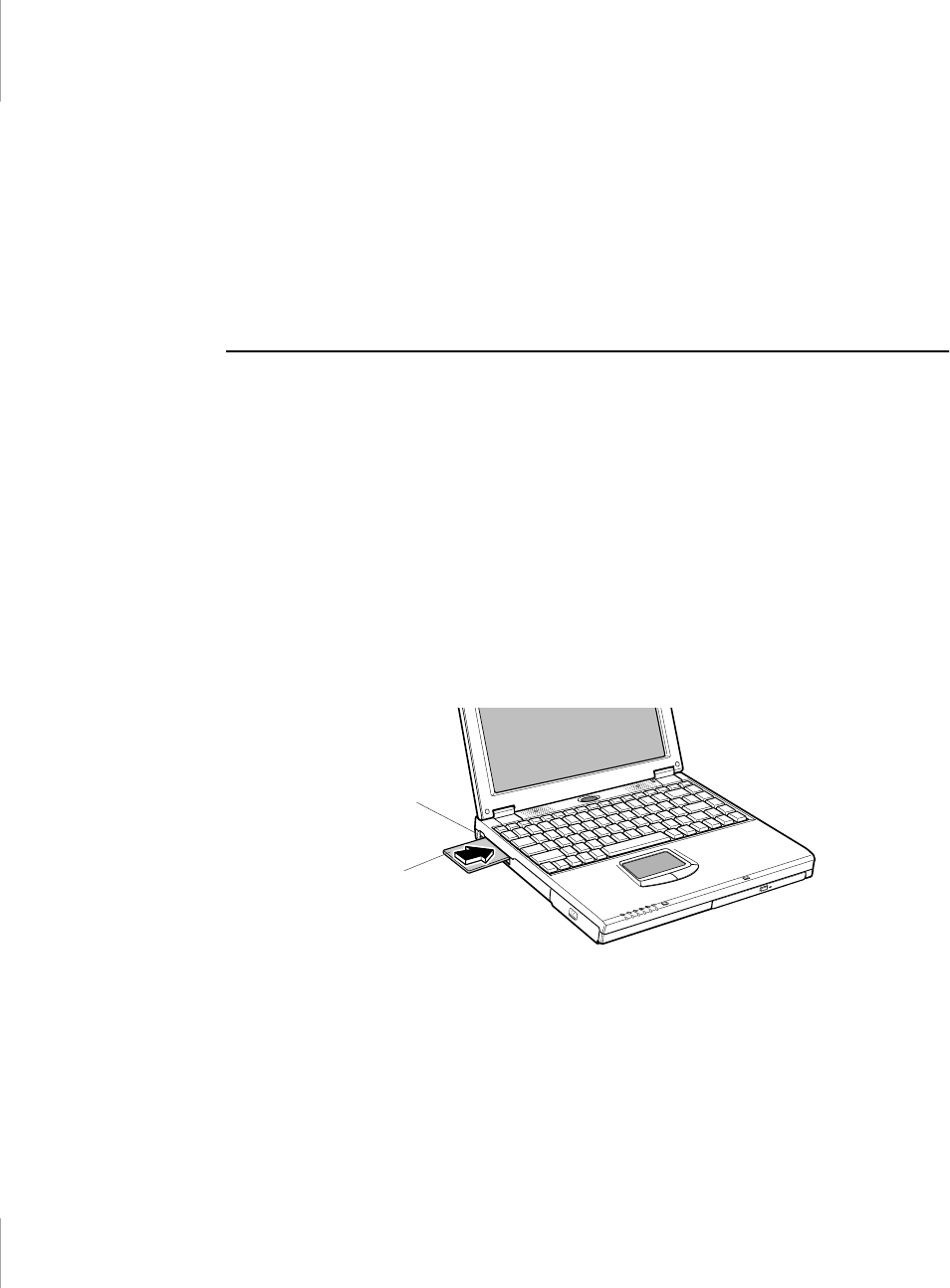
Using PC Cards
You can install PC Cards while the computer is on.
To insert a PC Card into a slot:
1. Push the slot door with a PC Card.
2. Align the card with a slot and insert the card into the slot until it locks in place
(Figure 21).
The eject button for the card slot operates in two steps.
To remove a PC Card:
1. push the eject button once to pop it outward.
2. Push the eject button again, then the card will be ejected.
Figure 21. Inserting a PC Card
Windows 98
Windows 98 automatically assigns computer resources (such as communication
ports and memory addresses) to a PC Card installed in your computer. For further
PC Card
Eject button

72 User’s Manual
information on configuring a PC Card in Windows 98, see the index entry PC card
in the Windows Help. Windows 98 also handles power management for PC Cards.
To remove a PC Card from your computer if your operating system is Windows
98:
Use the following procedures to remove PC Cards, or you
may lose data that is being stored to a card.
1. Click the PC Card icon on the taskbar.
2. Select the name of the card you want to remove, and then click the Stop button.
3. Push the card eject button on the side of the PC Card slot when prompted to do
so.
4. Pull the card out of the PC Card slot.
Windows NT
Systemsoft Card Wizard is shipped with this notebook computer that use Windows
NT as the operating system. When you install a PC Card, CardWizard attempts to
configure it automatically. If Card Wizard successfully assigns system resources
to your card, the computer beeps twice.
If CardWizard cannot automatically configure your PC Card, the computer beeps
once and a message appears telling you that the card has not been configured. Click
the Wizard button on the CardWizard window. CardWizard then analyzes why the
card was not configured and fixes the problem or gives you information to help fix
the problem.
CardWizard works with the PowerProfiler program to manage PC Cards when the
computer enters or resumes from rest mode. CardWizard gives you instructions to
prevent loss of data before the computer enters rest mode or may stop the computer
from entering rest mode. ATA and modem cards can enter rest mode.
Follow these guidelines when using PC Cards with CardWizard:
•Some of LAN (local-area network) cards can be inserted while the computer
is on but should be removed only when the system is turned off.
•SCSI cards should be inserted at startup to enable Windows NT to find the
device attached to the SCSI card. SCSI cards can be removed when the
computer is turned off. If you restart your computer without the SCSI card

Working with PC Cards 73
installed, a message may appear telling you that a service did not start. You
can ignore this message.
•Modem and ATA cards can be inserted and removed while the computer is
on.
Before you remove a modem or ATA card from your
computer, stop the card through the CardWizard program or
you may lose data.
To stop and remove a PC Card from your computer:
1. In the SystemSoft CardWizard screen, click with the right mouse button on the
name of the card you want to remove.
2. Click Stop in the Actions menu. A red stop sign appears on the main screen
when the card is stopped.
3. Click OK.
4. Push the card eject button on the side of the PC Card slot.
5. Pull the card out of the slot compartment.
For more information on using the CardWizard program, see the CardWizard
Help.

74 User’s Manual
Upgrading Memory
You can increase system memory by installing optional memory modules. You
can install a 16, 32, 64, 128, or 256 MB module.
To avoid possible system problems, use only approved
memory modules in your computer. Use the only one type
memory module, either EDO or SDRAM.
Before You Install Memory
To prevent personal injury and damage to the equipment,
follow the precautions listed here before installing a memory
module.
Take the following precautions when installing a memory module:
•Before you remove the memory module compartment door, turn off the
computer, unplug the power cord, and remove the battery. Also, disconnect
any peripheral devices.
•Before handling a memory module, discharge any static electricity by
touching a grounded surface or using a grounding wrist strap.
•Do not insert objects with conductive material, such as metal screwdrivers or
graphite pencils, into the memory-module compartment.
•Be careful in handling the metal plate of the memory door.
Installing a Memory Module
Handle a memory module carefully. Hold them only by the
edges.
To install a memory module:
1. Turn the computer over so that the bottom faces up.
Upgrading Memory 75
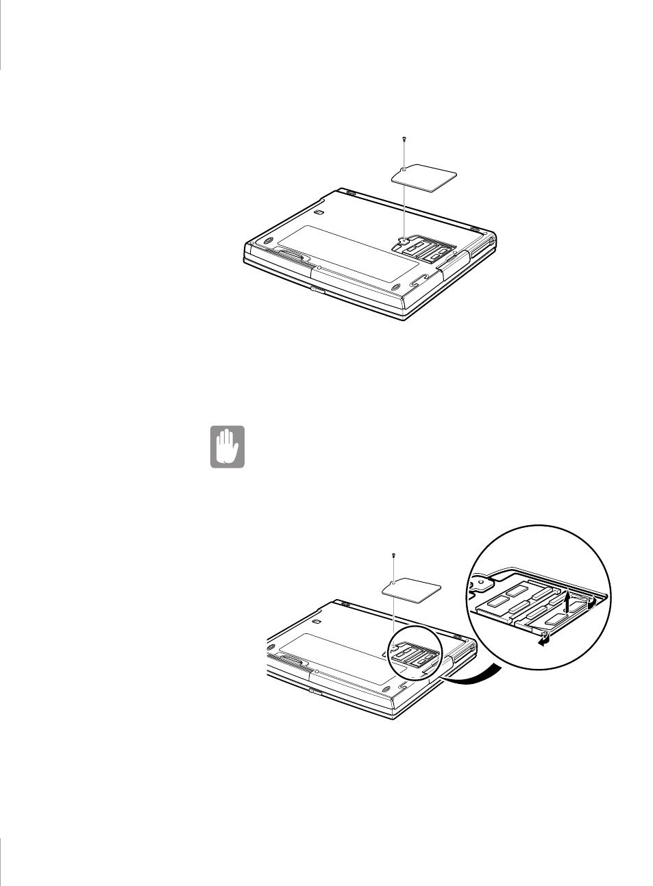
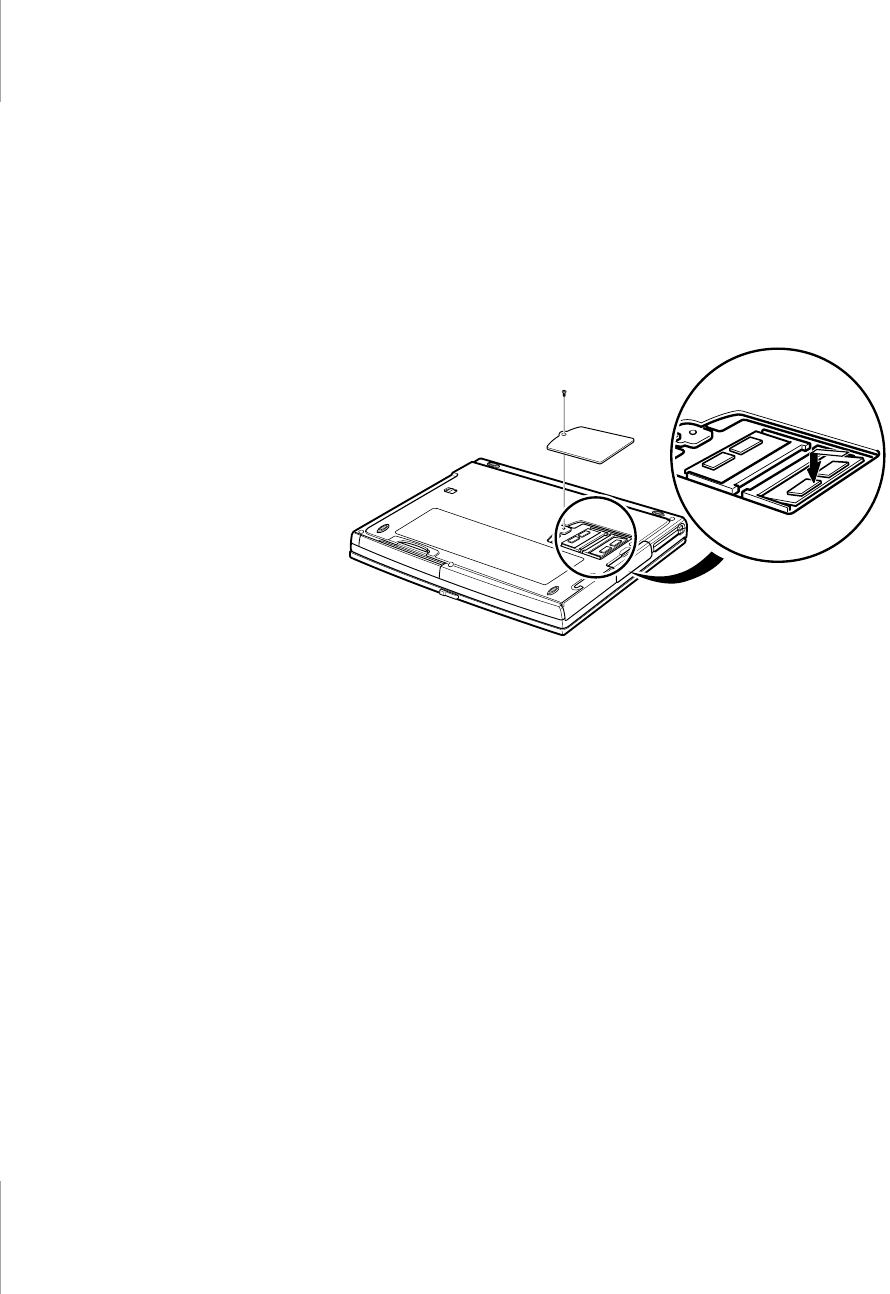
2. Using a screwdriver, remove the screw that holds the memory-module
compartment door in place (Figure 22).
Figure 22. Removing the Memory Module Compartment Door
3. Grasp the edge of the door and pull the door off the chassis.
4. Remove installed modules if necessary:
When removing modules, pull on the plastic portion of the
connector slots tabs only. Do not pull on the metal part of the
tabs, or you may damage the tabs.
a. Pull the tabs on the connector slot outward slightly, until the edge of
the memory module pops up (Figure 23).
Figure 23. Removing a Memory Module
Tab
Tab
76 User’s Manual
b. Hold the memory module by the edges and pull it forward out of the
compartment.
5. Align the connector on the memory module with the connector of the slot.
6. Push the memory module into the slot at a slight angle until the connectors are
fully engaged (Figure 24).
7. Push down on the edge of the memory module until the module snaps into
place.
Figure 24. Installing a Memory Module
8. Align the memory module compartment door with the compartment and push
the door down until it snaps into place.
9. Reinstall the screw you removed in step 2.
10. Turn on the computer and perform a complete POST to check the memory
integrity.

About Drivers and System Resources 77
About Drivers and System Resources
This section gives you basic information about drivers and system IRQs.
Drivers
A driver is a program that enables the operating system to work with a hardware
device. Your computer includes drivers for the audio, video, infrared, touchpad,
keyboard, CD-ROM drive, hard drive, floppy drive, and PC Card controller. When
you add a device to your computer, such as a printer, you install a driver for that
device. Different drivers are used by different operating systems.
IRQs
Most of the devices in your computer or connected to your computer need their
own IRQ (interrupt request line). The IRQ is a hardware line that a device can use
to send signals to the microprocessor. When the device needs the microprocessor’s
service, the device sends an interrupt request signal to the microprocessor.
The number of IRQs available for any computer is limited by industry standards.
Because it ships with numerous features, this computer uses most of the available
IRQs. If you add another device to your computer, you may need to disable an
existing device to free up an IRQ for the new device. IRQ resources are of
particular concern when the computer is attached to a docking device.
The default IRQ settings that are used by your computer are listed in Table 9 and
Table 10.
Table 9. IRQs, Windows 98 Systems
IRQ Component
0System timer
1Keyboard
2Internal Controller
3IrDA Port
4COM 1, COM 3

78 User’s Manual
Table 10. IRQs, Windows NT Systems
5Audio/USB
6Floppy controller
7 LPT1 (parallel port)
8CMOS/Clock
9ACPI bus SCI IRQ
10 Reserved
11 CardBus/Modem
12 Touchpad, PS/2 mouse
13 Numeric data processor
14 IDE 1 (hard drive)
15 IDE 2 (CD-ROM drive)
IRQ Component
0System timer
1Keyboard
2Internal Controller
3COM 2, COM 4
4 COM 1, COM 3
5Audio/USB
6Floppy controller
7 LPT1 (parallel port)
8CMOS/Clock
9Available
10 Available
11 CardBus/Modem
12 Touchpad, PS/2 mouse
13 Numeric data processor
14 IDE 1 (hard drive)
15 IDE 2 (CD-ROM drive)
IRQ Component

About Drivers and System Resources 79
In Windows 98, you can configure a device so that the device is disabled when you
connect your computer to a docking station but enabled when the computer is not
connected to the docking station. With this configuration, an IRQ is available for
a peripheral device that you connect to the docking station. See your Windows 98
manual for more information.

80 User’s Manual
Troubleshooting
If you ever have difficulty running your computer, follow these steps:
1. Consult the following sections for advice on how to handle system problems.
2. If steps 1 does not help you to resolve the problem, contact your reseller for
assistance.
Operating Problems
This section tells you what to do if you have problems running your computer. If
any problem persists after you take corrective action, contact your reseller for
assistance.
The computer does nothing when you turn it on.
Has the battery run down? Connect the power cord to get power and recharge the
battery. Try turning on the computer again.
The computer is not behaving as expected.
Operating your computer at high speed with the cache enabled may cause system
instability and incompatibility with some operating systems. If your computer is
not behaving as expected and no error messages appear, disable the External
Cache setting in the Memory Cache field of System Setup.
Nothing appears on the LCD panel when you turn on the computer.
Adjust the brightness on a TFT LCD. Are you using an external monitor? If so,
press <Fn+F5> to return to the LCD panel.
Nothing appears on the external monitor when you switch the display to it.
Is the monitor properly connected to the computer? Is the monitor’s power cord
connected to an AC wall outlet? Check the brightness and contrast controls on the
monitor. Does the program appear on the LCD panel instead of the external
monitor? If so, press <Fn+F5> to switch to the monitor. Try turning the monitor
off and on again.
The external monitor displays flashes or waves.
Check the cables between the monitor and the computer. Are they properly
installed?

Troubleshooting 81
Some of the letter keys type numbers instead of the indicated letters.
Is the Num Lock light on? If so, the numeric keypad on the keyboard is active. To
return the keypad keys to typing letters, press <Num Lock>.
Battery power seems to run out faster than expected.
If you are running the computer from the battery rather than the power cord, make
sure that you set the Idle Mode field in System Setup to On. This setting enables
the microprocessor and the hard drive to slow down when the computer is not
busy.
You can also enable other power-saving options through System Setup. Set the
timeout times in the Standby Timeout and Rest Timeout fields to the shortest times
to ensure maximum power savings.
Certain software programs “hang” during operations when there is no
interaction with the keyboard or peripheral devices.
Your computer may be in standby or rest mode. Tap the touchpad to resume from
standby or press the power button to resume from rest.
A serial or parallel device attached to a serial or parallel port on the rear
panel of the system unit does not work properly.
Check the attached device. Is it turned on? Is the cable properly installed between
the device and the port? If you are using an operating system that is not plug and
play compliant, make sure the Plug & Play O/S field in System Setup is set to No.
Check to make sure that the port is enabled in System Setup.
A PC Card does not work correctly.
Make sure that the PC Card is inserted left side up in the PC Card slot. Check that
the card is inserted fully into the slot. If you are using a PC Card modem, check
the modem cable connections. For the Windows 98 operating system, try setting
the Plug & Play OS field in System Setup to Yes to enable Windows 98 to
autosense an older PC Card. For the Windows NT operating system, make sure
Plug & Play O/S in System Setup is set to No.
The System Setup settings are not retained when you turn off the computer.
The CMOS battery inside the computer may need to be replaced. The CMOS
battery provides power to save the system BIOS information when the computer
is turned off. Normally, the CMOS battery lasts for several years. Do not attempt
to open the chassis and replace this battery yourself or your warranty is void. Have
an authorized the manufacturer’s service center replace the CMOS battery.

82 User’s Manual
Infrared Problems
If your computer’s operating system is Windows 98, you can enable and use the
infrared port. The Windows NT 4.0 operating system does not support infrared.
If you are unable to transfer files with the infrared port, check the following:
•Make sure the COM2 port field in System Setup is set to 2F8, IRQ 3. The field
is in the I/O Device Configuration under Advanced Menu.
•The receiving device must be positioned properly. There must be no more
than three feet of distance between the computer’s infrared port and the
receiving infrared device.
•The sending and receiving devices need to be on the same level vertically.
Place them on the same table if possible.
•Make sure the infrared ports on the sending and receiving devices face each
other, with no more than a 30 degree angle between the two infrared ports.
•Make sure that nothing is obstructing the file transfer path between the
computer’s infrared port and the receiving infrared device.
If you still cannot transfer a file, see the documentation for the infrared software.

Specifications 83
Specifications
Table 11 gives the specifications for 3-spindle type computer.
Table 11. System Specifications (3-spindle type computer)
Dimension
Width 12.2 in (31.0 cm)
Height 1.56 in (3.97 cm)
Depth 9.96 in (25.2 cm)
Weight (with Li-Ion battery & 13.3 in
TFT LCD & weight saver)
5.84 lb (2656 g)
LCD viewing area (13.3 TFT) 10.6 x 8.0 in (270.3 x 202.8 mm)
LCD viewing area (14.1 TFT) 11.2 x 8.4 in (285.7 x 214.3 mm)
Environment
Ambient temperature, operating 50o–90o F (10o–32oC)
Ambient temperature, storage 23o–104o F (-5o–40o C)
Relative humidity (noncondensing),
operating 20–80%
Relative humidity (noncondensing),
storage
5–90%
Altitude, operating 0 to 8,000 ft (0 to 2,348 m)
Altitude, storage 0 to 40,000 ft (0 to 12,192 m)
Shock, operating 10 G for 11 ms half sine
Shock, nonoperating 60 G for 11 ms half sine
Litume-Ion Smart Battery
Weight 0.92 lb (420 g)
Nominal open circuit voltage 11.1 VDC
Capacity, typical 5100 mAhr, 56.6whr
Charging time, approximate, with
computer turned off
3.0 hr (Li-Ion)
Charging time, approximate, with
computer turned on
5.0 hr (Li-Ion)

84 User’s Manual
Table 12 gives the specifications for 2-spindle type computer.
Table 12. System Specifications (2-spindle type computer)
Average battery life, with no power
management enabled
3.0 hr
External AC Adapter
Operating voltage 100~120 VAC to 200~240 VAC
Line frequency 50-60 Hz
Input current 1.5 A 100 V ~ 0.8 A 240 V
Output current 3.15 A
Output voltage 19.0 VDC
Dimension
Width 12.2 in (31.0 cm)
Height 1.3 in (3.29 cm)
Depth 9.96 in (25.2 cm)
Weight (with Li-Ion battery & 13.3 in
TFT LCD & weight saver)
5.26 lb (2393 g)
LCD viewing area (13.3 TFT) 10.6 x 8.0 in (270.3 x 202.8 mm)
LCD viewing area (14.1 TFT) 11.2 x 8.4 in (285.7 x 214.3 mm)
Environment
Ambient temperature, operating 50o–90o F (10o–32oC)
Ambient temperature, storage 23o–104o F (-5o–40o C)
Relative humidity (noncondensing),
operating
20–80%
Relative humidity (noncondensing),
storage
5–90%
Altitude, operating 0 to 8,000 ft (0 to 2,348 m)
Altitude, storage 0 to 40,000 ft (0 to 12,192 m)
Shock, operating 10 G for 11 ms half sine
Shock, nonoperating 60 G for 11 ms half sine

Specifications 85
Litume-Ion Smart Battery
Weight 0.92 lb (420 g)
Nominal open circuit voltage 11.1 VDC
Capacity, typical 5100 mAhr, 56.6whr
Charging time, approximate, with
computer turned off
3.0 hr (Li-Ion)
Charging time, approximate, with
computer turned on
5.0 hr (Li-Ion)
Average battery life, with no power
management enabled
3.0 hr
External AC Adapter
Operating voltage 100~120 VAC to 200~240 VAC
Line frequency 50-60 Hz
Input current 1.5 A 100 V ~ 0.8 A 240 V
Output current 3.15 A
Output voltage 19.0 VDC