Samsung Electronics Co SBT-CY71 BLE Module User Manual SWL A70U Datasheet
Samsung Electronics Co Ltd BLE Module SWL A70U Datasheet
Users Manual

REV 0.1
Samsung Electro-Mechanics Proprietary and Confidential
1/13
Revision Date
20160601
Revision No.
0.0
User Manual
SBT – CY71
802.15.1 BLE Module

Revision History
Revision
Date
Descriptions
0.0
2016-06-01
- Initial release
Table of Contents
1 GNENRAL DECRIPTION ...................................................................................................... 4
1.1 FUNCTIONAL DESCRIPTION .......................................................................................................... 4
1.2 FEATURES ............................................................................................................................... 4
2 DIMENSION , PIN ASSIGNMENTS , PICTURES ................................................................... 6
2.1 DIMENSION ............................................................................................................................. 6
2.2 PIN ASSIGNMENTS .................................................................................................................... 7
2.3 CONNECTOR SPECIFICATION ........................................................................................................ 8
3 ELECTRICAL CHARACTERISTICS(TBD) .............................................................................. 9
3.1 ABSOLUTE MAXIMUM RATINGS ..................................................................................................... 9
3.2 RECOMMENDED OPERATING CONDITIONS ........................................................................................ 9
3.3 ENVIRONMENTAL CHARACTERISTICS .............................................................................................. 9
4 RF SPECIFICATIONS ........................................................................................................ 10
4.1 RECEIVER RF SPECIFICATIONS (TBD) .......................................................................................... 10
5 PRODUCT LABEL INFORMATION ...................................................................................... 11
6 MANUFACTURING SITE ................................................................................................... 12
7 WARING & SAFETY INFORMATION .................................................................................. 13
1 Gnenral Decription
1.1 Functional Description
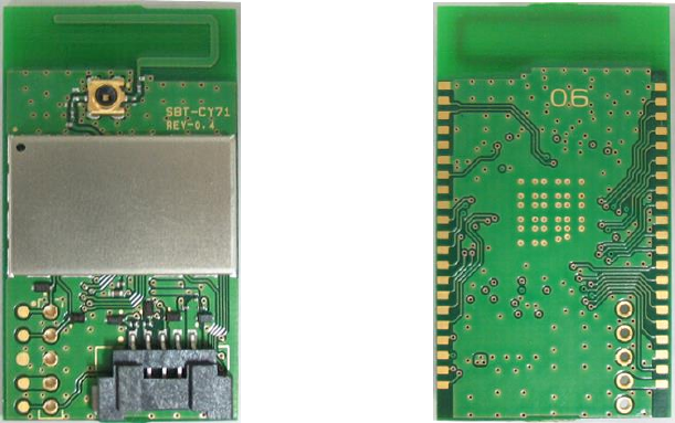
SBT-CY71 is the module for BLE at embedded and Digital appliance applications. It is based on
Cypress CYBL11171-56LQXI solution which comprises single chip with integrated BLE 4.2
Figure 1-1 Module Picture
1.2 Features
BLE - compliant
Supports Adaptive Frequency Hopping
On chip support for serial peripheral interface (master and slave modes)
Compact dimension: 3 5 mm x 2 0 mm / H max : 4.8 mm
Host Interfaces: UART Interface
RoHS compliant
1.2.1 Power Management
Supply voltage range
VCC 5V (4.5V ~ 5.5V)
1.2.2 Applications
Home appliances
( electric oven, Hood, Cooktop etc)
2 Dimension , Pin Assignments , Pictures
2.1 Dimension
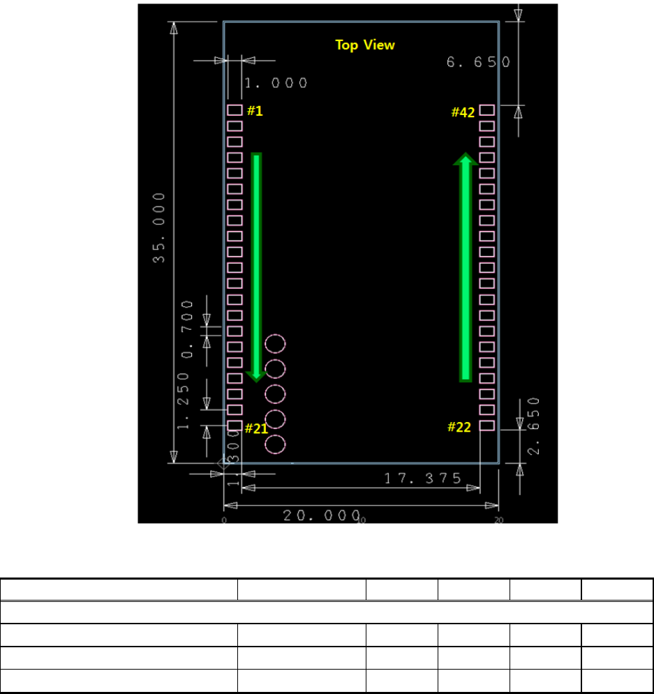
2.1.1 Module Dimension
- L X W X H = 20.0 x 35.0 x 4.8mm
Figure 2-1 Module Dimension
Parameter
Conditions
Min.
Nom.
Max.
Unit
Dimension (Module)
X
-
19.7
20
20.3
mm
Y
-
29.7
35
35.3
mm
Height
-
-
4.8
-
mm
2.2 Pin Assignments
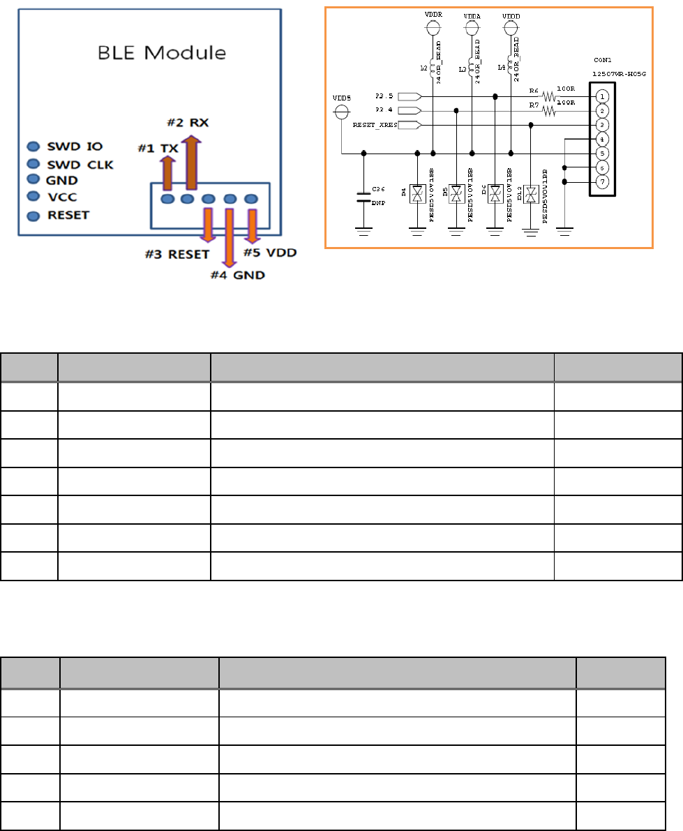
4.2.1 UART Interface
Figure 2-4 UART Pin Assignments (Top View)
No.
Pin Name
Description
Type
1
P3.5
UART TX
O
2
P3.4
UART RX
I
3
RESET_XRES
Reset
O
4
GND
Ground
G
5
VDD5
+5V Power supply for BLE
P
6
GND
Ground
G
7
GND
Ground
G
4.2.2 SWD Interface
No.
Pin Name
Description
Type
1
SWD DATA
SWD IO
I/O
2
SWD CLK
Clk
CLK
3
GND
Ground
G
4
VCC
VDD5
P
5
RESET
Reset
O
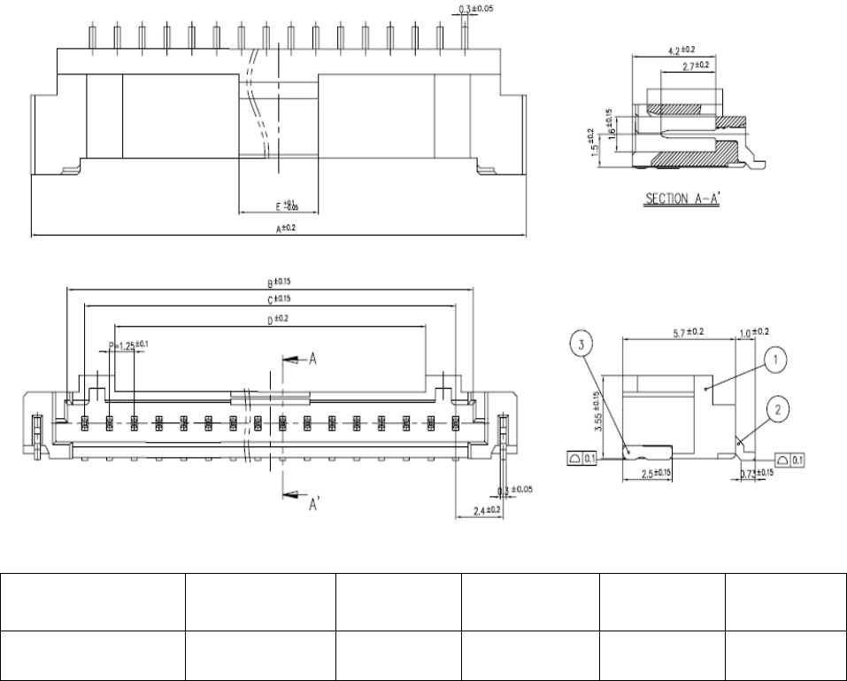
2.3 Connector Specification
PARTS NO.
A
B
C
D
E
12507WR-H05G
11.2
6.75
5.0
4.15
3.5

3 Electrical Characteristics(TBD)
3.1 Absolute Maximum Ratings
Symbol
Parameter
Min.
Max.
Unit
VDD_5
DC supply voltage
-
5.5V
V
3.2 Recommended Operating Conditions
Symbol
Parameter
Conditions
Min.
Nom.
Max.
Unit
VDD_5V
DC supply voltage from HOST
-
+4.5
+5
+5.5
V
Top
Operating temperature(Ambient)
-
0
-
+70
°C
3.3 Environmental Characteristics
Symbol
Parameter
Conditions
Min.
Max.
Unit
ESD
Electro-static discharge voltage
HBM
-4K
+4K
V
Top
Operating temperature
-
0
+70
°C
Tstg
Storage temperature
-
-30
+85
°C

4 RF Specifications
All measurements are made under nominal supply voltage, room temperature, and conducted conditions
at each antenna port except antenna.
4.1 Receiver RF Specifications (TBD)
Parameter
Conditions
Min
Typ.
Max
Unit
Frequency Range
2402+K*2MHz (K=0~39)
2402
-
2480
MHz
Receiver
Sensitivity (PER)
PER ≤30.8%
-
-
-70
dBm
Maximum Input Level
PER ≤30.8%
-10
dBm
Transmitter
Output Power
Average Power
-4
0
4
dBm
ICFT
-150
-
150
kHz
Frequency Drift
-50
-
50
Drift rate
-
-
20
kHz/50us
Frequency Deviation
Avg
(payload sequence 00001111)
225
-
275
kHz
Max
(payload sequence 10101010)
185
-
-
kHz
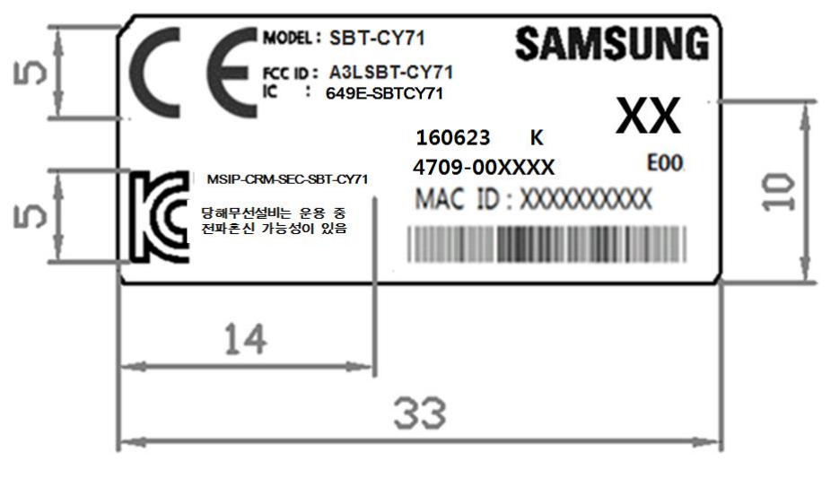
5 Product Label Information
6 Manufacturing Site
Samsung Electro-mechanics Thailand Co., Ltd. (SEMTHAI)
Wellgrow Industrial Estate, 93 Moo 5 T. Bangsamak, A.Bangpakong,
Chachoengsao 24180 THAILAND
Tel. : 66-38-562-000
Fax No. : 66-38-562-177
Instruction to OEM
This device complies with Industry Canada’s license-exempt RSSs. Operation is subject to
the following two conditions:
(1) This device may not cause interference and
(2) This device must accept any interference, including interference that may cause
undesired operation of the device.
This application and its antenna must not be co-located or operation in conjunction with
any other antenna or transmitter. A minimum separation distance of 20cm must be
maintained between the antenna and the person for this appliance to satisfy the RF
exposure requirements.
Host labeling requirement: “Contains transmitter module
FCC ID: A3LSBT-CY71
IC ID: 649E-SBTCY71”
This device complies with part 15 of the FCC Rules. Operation is subject to the following
two conditions:
(1) This device may not cause harmful interference and
(2) this device must accept any interference received, including interference that may cause
undesired operation.
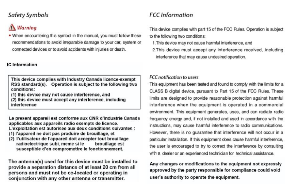
7 WARING & SAFETY INFORMATION