Samsung Electronics Co SCM140 Cable Modem User Manual
Samsung Electronics Co Ltd Cable Modem Users Manual
Users Manual

SCM-140U User Guide
CLASS B Digital device or Peripheral
This equipment has been tested and found to comply with the limits
for a Class B digital device, pursuant to Part 15 of the FCC Rules.
These limits are designed to provide reasonable protection against
harmful interference in a residential installation. This equipment
generates, uses and can radiate radio frequency energy and, if not
installed and used in accordance with the instructions, may cause
harmful interference to radio communications. However, there is no
guarantee that interference will not occur in a particular installation. If
this equipment does cause harmful interference to radio or television
reception, which can be determined by turning the equipment off and
on, the user is encouraged to try to correct the interference by one or
more of the following measures:
- Reorient or relocate the receiving antenna.
- Increase the separation between the equipment and receiver.
- Connect the equipment into an outlet on a circuit different from
that to which the receiver is connected.
- Consult the dealer or experienced radio TV technician for help.
iii
Stop using PC and get rid of all the cables, such as power cable,
coaxial cable, Ethernet cable and USB cable, connected to InfoRanger
and PC during a thunderstorm. An electrical interaction can cause
death, severe injury, or damage to the equipment.
The warranty will be voided should any of the following occur :
➀The warranty seal covering the screw under the cable modem is broken
or removed
➁The cable modem has been opened
➂There is substantial evidence that the cable modem's electronics have
been tampered with.
Samsung recommends to turn off and on the InfoRanger once in a while to
triger to download the latest software automatically.
Copyright © Samsung Electronics Co. Ltd. And Samsung Telecommunications America, Inc. 2001
All rights reserved. Samsung, the Samsung logo, Samsung InfoRanger are
registered trademarks. All other product names are used for identification only
and may be trademarks and/or registered trademarks of their respective
companies. Product specifications subject to change without notice.
No part of this publication may be reproduced in any form or by any means or
used to make any derivatives such as translation, transformation, or adaptation
without permission from Samsung Electronics as stipulated by the United States
Copyright Act of 1976.

iv
Limited Warranty
1. What Is Covered And For How
1. What Is Covered And For How 1. What Is Covered And For How
1. What Is Covered And For How Long ?
Long ?Long ?
Long ? SAMSUNG TELECOMMUNICATIONS AMERICA,
INC.(“SAMSUNG”)warrants to the original purchaser that SAMSUNG’s Cable Modems are free from defects in
material and workmanship under normal use and service for the period commencing upon the date of purchase and
continuing for the following specified period of time after that date :
InfoRangerTM Cable Modem 2 years
2. What is not covered?
2. What is not covered?2. What is not covered?
2. What is not covered? This Limited Warranty is conditional upon proper use of the product by the purchaser. The
Limited Warranty does not cover : (a) defects or damage resulting from accident, misuse, abuse, neglect, unusual
physical, electrical or electromechanical stress, modification of any part of the product, or cosmetic damage; (b)
equipment that has the serial number removed or made illegible;(c) all plastic surfaces and other externally exposed
parts that are scratched or damaged due to normal use;(d) malfunctions resulting from the use of the product in
conjunction with accessories, products or ancillary or peripheral equipment not authorized and approval of by
SAMSUNG; (e) defects or damage from improper testing, operation, maintenance, installation, or adjustment. Please
call SAMSUNG’s customer care center at 1-888-987-4357 for updated pricing on non-warranty repairs.
3. What Are
What Are What Are
What Are SAMSUNG
SAMSUNGSAMSUNG
SAMSUNG’s
ss
s Obligations?
Obligations? Obligations?
Obligations? During the applicable warranty period, SAMSUNG will repair or replace, at
SAMSUNG’s sole option, without charge to purchaser, any defective component part of the Cable Modem or accessory.
To obtain service under this Limited Warranty, purchaser must return the product to an authorized SAMSUNG service
facility in an adequate container for shipping, accompanied by purchaser’s sales receipt or comparable substitute proof of
purchase showing the date of purchase, the serial number of the product, and the sellers name and address. To obtain
assistance on where to deliver the Cable Modem, call SAMSUNG customer care at 1-888-987-4357. Upon receipt,
SAMSUNG will promptly repair or replace the defective product. SAMSUNG may, at SAMSUNG’s sole option, use
rebuilt, reconditioned, or new parts or components when repairing any product or replace a product with a rebuilt,
reconditioned or new product. Repaired products will be warranted for a period equal to the remainder of the original
Limited Warranty on the original product or for 90 days, which ever is longer. All replaced parts, components, boards
and equipment shall become the property of SAMSUNG. If SAMSUNG determines that the product is not covered by
this Limited Warranty or that the product is not defective, the purchaser must pay all parts, shipping, and labor charge
for the testing, repair and return of the product.
4. What Are The Limits On
What Are The Limits On What Are The Limits On
What Are The Limits On SAMSUNG
SAMSUNGSAMSUNG
SAMSUNG’
’’’s Liability?
s Liability?s Liability?
s Liability? THE WARRANTIES GIVEN IN THIS WARRANTY ARE LIMITED
TO THE DURATION OF THIS LIMITED WARRANTY SET OUT ABOVE. EXCECT TO THE EXTENT
PROHIBITED BY APPLICABLE LAW, SAMSUNG SHALL NOT BE LIABLE FOR ANY SPECIAL, INCIDENTAL,
CONSEQUENTIAL, INDIRECT OR SIMILAR DAMAGES, LOSS OF PROFITS, DAMAGES TO PURCHASER
PROPERTY, OR INJURY TO PURCHASER OR OTHERS ARISING OUT OF THE USE, MISUSE OR INABILITY TO
USE ANY SAMSUNG CABLE MODEM, BREACH OF WARRANTY, BREACH OF CONTRACT, OR NEGLIGENCE,
INCLUDING BUT NOT LIMITED TO SAMSUNG’S OWN NEGLIGENCE, EVEN IF SAMSUNG OR ITS AGENT HAS
BEEN ADVISED OF SUCH DAMAGES, OR FOR ANY CLAIM BROUGHT AGAINST PURCHASER BY ANY OTHER
PARTY. THIS LIMITED WARRANTY IS THE COMPLETE WARRANTY FOR SAMSUNG’S CABLE MODEM, AND
SAMSUNG HEREBY DISCLAIMS ANY OTHER WARRANTIES, EXPRESS OR IMPLIED, IMCLUDING ANY

v
IMPLIED WARRANTY OF MERCHANTABILITY OR FITNESS FOR A PARTICULAR PURPOSE. THIS LIMITED
WARRANTY SHALL NOT EXTEND TO ANYONE OTHER THAN THE ORIGINAL PURCHASER OF THIS
PRODUCT AND STATES PURCHASER’S EXCLUSIVE REMEDY. IF ANY PORTION OF THIS WARRANTY IS
ILLEGAL OR UNENFORCEABLE BY REASON OF ANY LAY, SUCH PARTIAL ILLEGALITY OR
UNENFORCEABILITY SHALL NOT AFFECT THE ENFORCEABILITY OF THE REMAINDER OF THIS LIMITED
WARRANTY WHICH PURCHASER ACKNOWLEDGES IS AND ALWAYS WILL BE CONSTRUCTED TO BE
LIMITED BY ITS TERMS OR AS LIMITED AS THE LAW PERMITS.
The Limited Warranty allocates the risk of product failure between purchaser and SAMSUNG, and SAMSUNG’s product
pricing reflects this allocation of risk and the limitations of liability contained in this Limited Warranty. The agents,
employees, distributors, and dealers of SAMSUNG are not authorized to make modifications to this Limited Warranty,
or make additional warranties binding on SAMSUNG. Accordingly, additional statements such as dealer advertising or
presentation, whether oral or written, do not constitute warranties by SAMSUNG and should not be relied upon. 5.
5.5.
5.
5. How Does State Law Apply To This Warranty?
5. How Does State Law Apply To This Warranty?5. How Does State Law Apply To This Warranty?
5. How Does State Law Apply To This Warranty? SOME STATES DO NOT ALLOW THE EXCLUSION OR
LIMITATIONS OF INCIDENTAL OR CONSEQUENTIAL DAMAGES OR HOW LONG AN IMPLIED WARRANTY
LASTS, SO THE ABOVE LIMITATIONS OR EXCLUSIONS MAY NOT APPLY TO YOU IN THEIR ENTIRETY.
The Limited Warranty gives you specific legal rights. You may also have other rights that vary from one jurisdiction to
another.
SAMSUNG Telecommunications America, Inc.
1601 East Plano Parkway Suite 150
Plano, TX 75074
Tel : 1-888-987-HELP(4357)
Fax : 1-972-761-7501
The software provided with this product is not covered under the hardware warranty described above. See Minimum
End-User Software License Terms which was shipped with the product for details on the software warranty.

vi
Intellectual Property
All Intellectual Property, as defined below, owned by or which is otherwise the
property of Samsung or its suppliers relating to the InfoRanger™, including but
not limited to, accessories, parts or software relating thereto (the Cable Modem
System), is proprietary to federal laws and state laws, and international treaty
provisions. Intellectual Property includes, but is not limited to, inventions
(patentable or unpatentable), patents, trade secrets, copyrights, software,
computer programs, and related documentation and other works of authorship.
You may not infringe or otherwise violate the rights secured by the Intellectual
Property. Moreover, you agree you will not (and will not attempt to) modify,
prepare derivative works of, reverse engineer, decompile, disassemble, or
otherwise attempt to create source code from the software.
No title to or ownership in the Intellectual Property is transferred to you. All
applicable rights of the Intellectual Property shall remain with Samsung and its
suppliers.
© 2001 Samsung Electronics Co., LTD. All rights reserved. No reproduction in whole
or in part allowed prior written approval.

vii
About This Guide
This manual is for users of the SAMSUNG InfoRangerTM cable modem. This
manual includes an introduction of the InfoRanger and shows how to install,
connect to a network, and use the InfoRanger. It also explains various problems
that the user may encounter while using the InfoRanger and how to troubleshoot
these problems.
Users who are accustomed to cable modem products as well as first time users
should read this manual carefully before installing and using the InfoRanger.
If you have any questions about this product or you think that the product is
damaged, please contact the SAMSUNG customer service center, as described in
the technical support page at the end of this manual or at the store where you
purchased this product.

viii
Document Organization
This InfoRanger User Guide includes the following contents in each chapter.
Chapter 1 Introduction to the InfoRanger explains the features of the cable modem,
the reasons for its wide use, the features and advantages of the InfoRanger.
Chapter 2 Prior to Installation explains the items that the user should prepare prior
to installing the InfoRanger. It also explains the environment configuration of a PC
for use with the InfoRanger.
Chapter 3 Installing the InfoRanger explains how to install the InfoRanger and how
to connect cables.
Chapter 4 Using the InfoRanger explains the names and features of each part of the
InfoRanger, how to distinguish the product status from the LEDs and how to
check whether the product is installed correctly or not.
Appendix A Troubleshooting
explains how to troubleshoot various problems that
may occur while using the InfoRanger.
Appendix B Product Specifications explains the specification of the InfoRanger in
table format.
Appendix C Glossary explains the terms that are useful when you use the
InfoRanger.
Appendix D Cable Specifications explains the cable specifications that are used to
connect the InfoRanger.

ix
Table of Contents
Chapter 1 Introduction to the InfoRanger ................. 1-1~1-4
Features of the InfoRanger ........................................................................ 1-2
Examples of Network Connection .............................................................. 1-3
Chapter 2 Prior to Installation ................................ 2-1~2-10
Subscribing to Cable Internet Service ........................................................ 2-1
Environment Preparation for Installation .................................................... 2-2
Preparing the Necessary Items .................................................................. 2-4
Configuring TCP/IP Protocol ...................................................................... 2-6
Installing TCP/IP Protocol on IBM Compatible PC ....................................... 2-7
Installing TCP/IP Protocol on Macintosh PC ................................................. 2-9
Chapter 3 Installing the InfoRanger ........................ 3-1~3-16
Locating in a Place ..................................................................................... 3-2
Connecting the Coaxial Cable .................................................................... 3-4
Connecting PCs ......................................................................................... 3-5
Single PC Connection ...................................................................................... 3-6
Multiple PCs Connection ............................................................................... 3-12
Connecting the Power Adapter ................................................................ 3-14
Inspecting Cable Connection ................................................................... 3-15
Chapter 4 Using the InfoRanger ................................ 4-1~4-5
Front View .................................................................................................. 4-1
Rear View ................................................................................................... 4-4
Appendix A Troubleshooting .................................. A-1~A-2
Appendix B Product Specifications ........................... B-1~B-2
Appendix C Glossary ................................................ C-1~C-4

x
Appendix D Cable Specifications .............................. D-1~D-4
RJ-45 Ethernet Cable ................................................................................. D-1
Twisted pair category-3,4,5 straight-through cable ....................................... D-1
Twisted pair category-3,4,5 crossover cable .................................................. D-2
USB Cable ................................................................................................. D-3

xi
List of Figures
Figure 1-1 Network connection if you subscribe to both cable TV
and the cable Internet service ............................................................. 1-3
Figure 1-2 Network connection if you only subscribe to a cable
Internet service .................................................................................... 1-4
Figure 2-1 Included items in the InfoRanger package ......................................... 2-4
Figure 3-1 Fixing the protrusion on the front to the groove of the
stand holder .......................................................................................... 3-2
Figure 3-2 Press the stand holder to the InfoRanger ........................................... 3-2
Figure 3-3 InfoRanger with stand holder .............................................................. 3-3
Figure 3-4 Connecting the coaxial cable to the Cable connector ........................ 3-4
Figure 3-5 Connecting the RJ-45 Ethernet cable to the Ethernet port
and a single PC ..................................................................................... 3-6
Figure 3-6 Connecting the USB cable to the USB port
and a single PC ..................................................................................... 3-7
Figure 3-7 Connecting the InfoRanger to multiple PCs through
an Ethernet hub ................................................................................. 3-13
Figure 3-8 Connecting the power adapter .......................................................... 3-14
Figure 3-9 Cable connection in case of a single PC connection ........................ 3-15
Figure 3-10 Cable connection in case of multiple PCs connection ..................... 3-16
Figure 4-1 Front View of the InfoRanger .............................................................. 4-1
Figure 4-2 Rear View of the InfoRanger ............................................................... 4-5
Figure D-1 Provided straight-through cable with RJ-45 connectors ................... D-1
Figure D-2 Pin Signals of the straight-through cable ........................................... D-1
Figure D-3 Pin connections of the straight-through cable ................................... D-1
Figure D-4 Crossover cable with RJ-45 connectors ............................................. D-2
Figure D-5 Pin Signals of the crossover cable ...................................................... D-2
Figure D-6 Pin connections of the crossover cable............................................... D-2
Figure D-7 USB connector termination ................................................................ D-3
Figure D-8 USB Cable ........................................................................................... D-3
Figure D-9 Pin Signals of the USB cable .............................................................. D-4

xii
(This page is left blank intentionally.)

1-1
Chapter
1Introduction
to
the
InfoRanger
The SAMSUNG InfoRanger is an external cable modem, which enables high-
speed data communication using a cable TV network.
With the SAMSUNG InfoRanger, you can receive data at 40Mbps, and send data at
10Mbps. Compared with conventional telephone lines, this remarkable speed is
100 times faster than 56Kbps modem.
SAMSUNG InfoRanger is specially designed for the users who want to transmit
data at high speed with lower cost. With SAMSUNG InfoRanger, you can enjoy
the highest communication.
InfoRanger speed can be changed by the following factors.
yUser’s computer specifications
yNumber of programs
yNetwork traffic when user is connected
yBandwidth provided by your service provider to the users

1-2 Chapter 1
Introduction to the InfoRanger
Features of InfoRanger
High speed
The InfoRanger enables you to connect to the Internet, transmit e-mails, and
download data up to 100 times faster than a 56Kbps modem.
Two-way data communication
The InfoRanger provides two-way data communication. With the InfoRanger, you
can download data up to 40Mbps, and simultaneously upload data up to 10Mbps.
Excellent Compatibility : DOCSIS-compliant InfoRanger
In compliance with DOCSIS (Data Over Cable Service Interface Specification),
the InfoRanger can receive services from all cable operators and can be used with
other DOCSIS compliant’s CMTS(Cable Modem Termination System).
Quick and easy installation process
With the InfoRanger, the IP address is set automatically. You only have to connect
the cables and any setting up procedure according to this guide.
Compact and convenient design
The InfoRanger is designed for easy to use and it fits well in any office
environment.
Support USB port
The InfoRanger supports USB port so that you can save trouble to open the case
of PC and install network interface card. It is a fast, bi-directional isochronal, low-
cost, dynamically attachable serial interface that is consistent with the
requirements of the PC platform. It supports up to 127 physical devices, and its
transfer rate assures up to 12Mb/s.
1-3
Examples of Network Connection
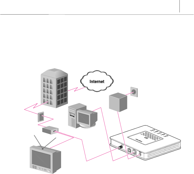
If you subscribe to both Cable TV and the Cable Internet Services
Figure 1-1 Network connection if you subscribe to both cable TV and the cable Internet service
Cable TV service provider
Cable outlet
Cable splitter
Coaxial cable
Ethernet cable
Television
PC Power adapter
InfoRanger
1-4 Chapter 1
Introduction to the InfoRanger
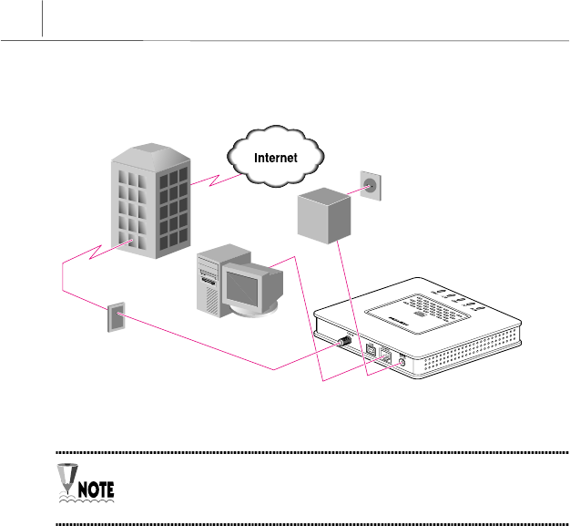
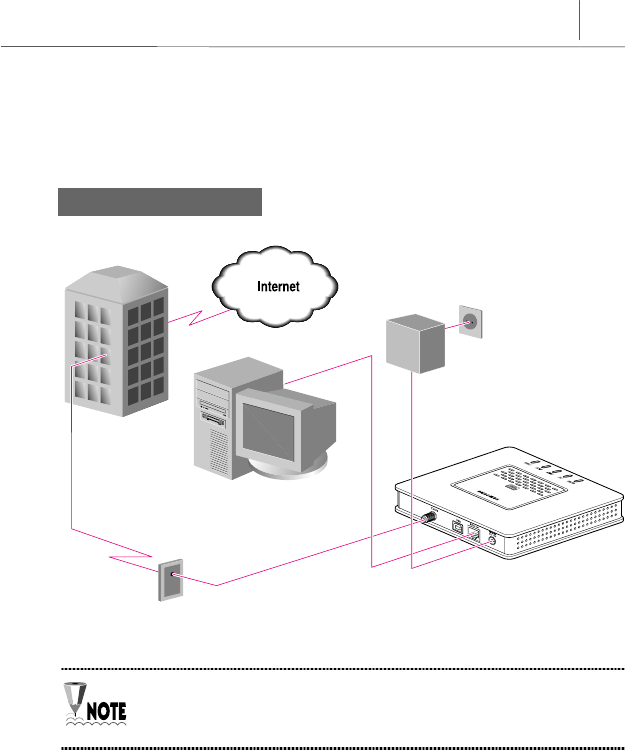
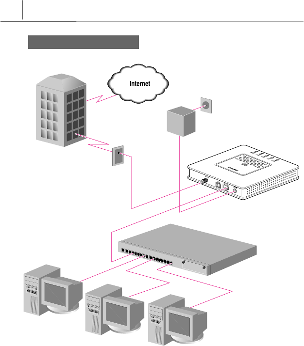
If you only subscribe to a Cable Internet Service
Figure 1-2 Network connection if you only subscribe to a cable Internet service
The above example is showing the case of connecting the PC to Ethernet
port of InfoRanger. The case of connecting the PC to USB port of
InfoRanger is identical.
PC
Ethernet cable
Coaxial cable
Cable outlet
Cable TV service provider
InfoRanger
Power adapter


2-1
Chapter 2 Prior to Installing
This chapter explains what you should do before installing the InfoRanger.
Subscribing to Cable Internet Service
The cable modem receives data through a cable TV network. Therefore, it is
necessary to have a cable Internet service to use your cable modem. If you are
already subscribing to cable TV, please make sure that you are also subscribing to
cable Internet service. If you do not have cable Internet service, contact your
cable TV provider and ask the following services.
yWhether they support two-way cable modem access service
or not.
☞The InfoRanger enables two-way data communication. If you want to use
all features of the InfoRanger, you need to subscribe to a cable TV
provider which provides two-way cable modem access service.
yWhether they provide the Internet service or not.
☞If you want to send or receive e-mails, access to WWW and/or use other
Internet services through the cable modem, you need to have cable
Internet service. Once you are an Internet service subscriber, your cable
TV provider will provide you with an Internet account, which you can
connect to via your cable modem. Please note that your Internet account
should be established before the installation of cable modem.
2-2 Chapter 2
Prior to Installing
Environment Preparation for Installation
The InfoRanger should be kept at moderate temperature, humidity, and stable
electric power. The recommended environment is as follows :
yOperation temperature : 32°F to 104°F
Storage temperature : - 13°F to 158°F
yOperation humidity : below 90% (104°F, non-condensing),
Preservation humidity : below 90% (140°F, non-condensing)
yPower Consumption : 7 Watt
yInput voltage : AC 120V
yRated frequency : 60Hz
While the InfoRanger is operating, keep the fluctuation range of input
voltage within 5% of regulated voltage. In addition, ground the electric
outlet which is connected to input terminal.
Avoid static electricity and electric noise….
Use preventive equipment if the InfoRanger is
installed in a place where high static electricity
or electric noise is present.
Clean and well ventilated place….
Install the InfoRanger in a ventilated place
where the appropriate temperature and airflow
is present. As dust can cause a serious failure of
operation, install the InfoRanger at a clean place.

2-3
Avoid the direct sunlight
Direct sunlight can increase temperature of the
InfoRanger and this can cause damage to
operational parts and lead to operation failure.
Therefore, Samsung recommends keeping the
InfoRanger away from direct sunlight.
2-4 Chapter 2
Prior to Installing
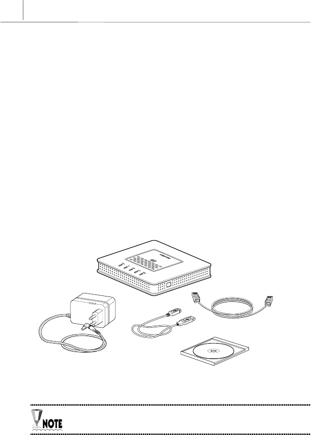
Preparing the Necessary Items
The following items should be prepared in order to use the InfoRanger.
Included Items
yInfoRanger (SCM-140U)
yA power adapter
yA stand holder
yA RJ-45 Ethernet cable (6Ft.)
yA USB cable (6Ft.)
yThis Manual
yUSB Driver Floppy Diskette for USB port (used for both Windows 98 SE
(Second Edition) and Windows 2000 environment)
Figure 2-1 Included items in the InfoRanger package
Specification and shape of the power cable contained in the package may
vary according to the regions where InfoRanger is purchased.
InfoRanger SCM-140U
RJ-45 Ethernet cable
(Straight –through cable)
Power adapter
This manual
USB cable
2-5
Not Included Items
The following items are not included in the InfoRanger package. These need to be
prepared separately.
yAn IBM compatible PC which TCP/IP is installed on and runs Windows 95 (or
later) or a Macintosh which TCP/IP is installed on and runs System 7.5 (or
later).
yA two-way coaxial cable
yA crossover cable for connecting hub
yA Network Interface Card (NIC)
If a user needs more than one straight-through cable, he/she should
prepare the necessary ones by himself/herself because only one straight-
through cable is supplied with InfoRanger by default.
It is necessary to prepare IBM-compatible PC running Windows 98 SE
(Second Edition) or later version, such as Windows Me(Millenium Edition) or
Windows 2000, to use USB port.
2-6 Chapter 2
Prior to Installing
Configuring TCP/IP Protocol
Once you have set-up the IBM compatible PC running on Windows 95 (or later)
or the Macintosh running on System 7.5(or later), you need to install TCP/IP
protocol and network interface card, only when using Ethernet port of InfoRanger.
You do not need to install TCP/IP protocol when using USB port, because TCP/IP
protocol is installed automatically while USB driver is installed. Skip this section
and go to the next chapter when using USB port.
Referring to the manual that provided with your network interface card, please
install the network interface card on your computer and install the network
interface card driver. Then, install TCP/IP protocol as follows. If you already
installed TCP/IP protocol, skip this section and go to the next chapter.
The TCP/IP protocol is installed automatically during Windows 2000
installation. Generally it is not necessary to install TCP/IP protocol in
Windows 2000 environment unless you removed TCP/IP protocol on
purpose.

2-7
Installing TCP/IP Protocol on IBM Compatible PC
This installation is an example of an IBM compatible PC running on
Windows 98 SE (Second Edition)/2000. Installation of TCP/IP protocol may
vary depending on the different operating system and/or a network
interface card used and/or Cable Service Provider, but the overall process is
generally similar. Contact the Cable Service Provider to install TCP/IP
protocol accuately.
For Windows 98 SE
1. Click the [Start] button on the desktop, and click Settings Î
ÎÎ
Î Control Panel.
2. In <Control Panel> window, double click
Network
icon.
3. When <Network> window appears, click
[Add…] button.
4. When <Select Network Component> window appears, click Protocol and then
click [Add…] button.
5. When <Select Network Protocol> window appears, click Microsoft from the
‘Manufacture’ list and then click TCP/IP from the ‘Network Protocols’ list. Click
[OK] button. Insert Windows 98 SE CD into CD-ROM drive and designate its
location in case a pop up window requesting to insert Windows 98 SE CD
appears. Otherwise you do not need to.
6. In <Network> Window, click TCP/IP from ‘The following network components
are installed’ list and click [Properties] button.
7. When <TCP/IP Properties> window appears, click <IP Address> tab. On the
<IP Address> tab, select Obtain an IP address automatically item and then click
[OK] button.
8. When the system reboot prompt message appears, click [Yes].

2-8 Chapter 2
Prior to Installing
For Windows 2000
1. Click the [Start] button on the desktop, and click Settings Î
ÎÎ
Î Control Panel.
2. In <Control Panel> window, double click
Network and Dial-Up Connections icon.
3. When <Network and Dial-Up Connection> window appears, select Local Area
Connection icon and press the right button of the mouse.
4. When <Local Area Connection Properties> window appears, Click [Install]
button.
5. When <Select Network Component Type> window appears, select Protocol
and then click [Add…] button.
6. When <Select Network Protocol> window appears, select Internet Protocol
(TCP/IP) and click [OK] button. TCP/IP protocol is installed. While TCP/IP is
installed, insert Windows 2000 CD into CD-ROM drive and designate its
location in case a pop up window requesting to insert Windows 2000 CD
appears. Otherwise you do not need to.
7. Select the newly installed Internet Protocol (TCP/IP) in <Select Network
Protocol> window, click [Properties] button.
8. When <Internet Protocol (TCP/IP) Properties> window appears, select
Obtain an IP address automatically item and Obtain DNS Server address
automatically item then click [OK] button.
9. When the system reboot prompt message appears, click [Yes]. Otherwise, it is
not necessary to reboot the system.

2-9
Installing TCP/IP Protocol on Macintosh PC
This installation is an example of a Macintosh running on System 8.5.
Installation method of TCP/IP protocol may vary depending on the different
operating system and/or a network interface card used and/or the Cable
Service Provider, but the overall process is generally similar. Contact the
Cable Service Provider to install TCP/IP protocol accuately.
1. Click the Apple icon and select the TCP/IP icon in the Control Panels.
2. In <TCP/IP> window, there are two menus, AppleTalk and Ethernet, in the
Connect Via list. Select Ethernet in the list.
3. The Setup box is changed. There are 4 menus in the Configure list. Select
Using DHCP Server in the list. Clicking this menu brings the IP address, router
address to be set automatically by InfoRanger.
4. Close the window to finish the TCP/IP installation. When <Save changes to
the current configuration?> message appears, click [Save].
5. If a message appears to restart the system, reboot the system. Otherwise you
do not need to.

2-10 Chapter 2
Prior to Installing
(This page is left blank intentionally.)


3-1
Chapter
3
Installing the InfoRanger
This chapter explains how to install the InfoRanger and how to connect the cables
to the InfoRanger. The following describes the process.
1. Connect the coaxial cable.
2. Connect to PC (Single PC / Multi PCs).
3. Connect the power adapter.
Do not conn
Do not connDo not conn
Do not conne
ee
ect the InfoRanger
ct the InfoRangerct the InfoRanger
ct the InfoRanger’
’’
’s power adapter before connecting any
s power adapter before connecting anys power adapter before connecting any
s power adapter before connecting any
cables to it.
cables to it.cables to it.
cables to it. It can cause serious damage to the equipment.
3-2 Chapter 3
Installing the InfoRanger
USB
Cable
Ethernet
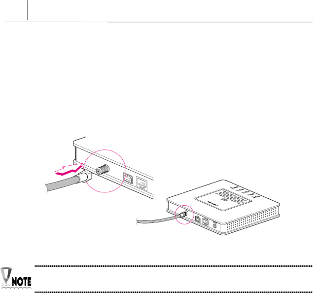
Connecting the Coaxial Cable
Connect one end of the coaxial cable to the Cable connector of the InfoRanger and
connect the other end of the coaxial cable to the cable outlet or cable splitter.
Slide the pin in the center of the coaxial cable into the hole in the Cable connector
carefully without bending, and turn the connector clockwise until the cable is
firmly attached.
Figure 3-4 Connecting the coaxial cable to the Cable connector
The coaxial cable is not provided by default.
3-3
Connecting PCs
You can connect the InfoRanger to a single PC or to group of PCs through a hub or
a switch. You must use RJ-45 Ethernet cable (straight-through cable) or USB
cable which are provided with the InfoRanger to connect the InfoRanger to PC. To
connect additional PCs to the InfoRanger, you must prepare the additional
Straight-through Ethernet cables, a hub, and a Crossover Ethernet cable.
You can use both Ethernet port and USB port at a time without any kind of
specific operation.
Use Ethernet port and prepare Network Interface Card and a Hub to
connect the InfoRanger to multiple PCs. You can connect the USB port to
only one PC at a time. Or, use both Ethernet port and USB port
simultaneously.
It is possible to connect the InfoRanger to multiple PCs by using USB port
and Ethernet port at the same time, but the amount of PCs is dependent on
the Cable Service Provider. Contact your Cable Service Provider for further
information.
3-4 Chapter 3
Installing the InfoRanger
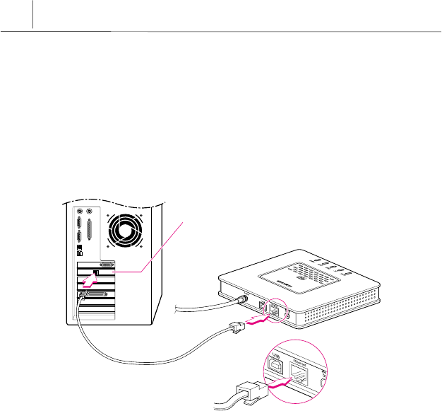
Single PC Connection
(1) Using Ethernet port
First, turn off the PC, which you connect to the InfoRanger. Connect the Ethernet
port of the InfoRanger to the port of the network interface card on the PC using
the RJ-45 network cable (provided with the InfoRanger).
Figure 3-5 Connecting the RJ-45 Ethernet cable to the Ethernet port and a PC
Network Interface Card
straight-through Cable
3-5
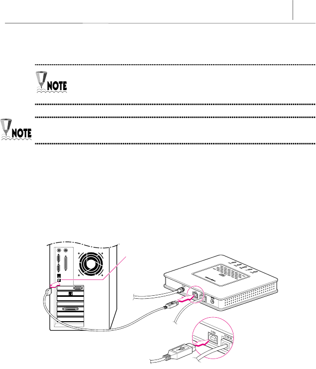
(2) Using USB port
Use IBM compatible PC running Windows 98 SE (Second Edition)or later
version such as Windows Me (Millenium Edition) and Windows 2000 in
case of using USB port.
The specifications of USB cable are described at Appendix D in detail.
To use USB port, there should be a USB port in the PC supposed to be connected
to InfoRanger. Make sure if there is a USB port in the PC most of all.
Connect the USB port of PC and the USB port of InfoRanger using USB cable,
which is provided with InfoRanger. It is not necessary to turn off the PC to
connect the PC to InfoRanger.
Figure 3-6 Connecting the USB cable to the USB port and a PC
USB Port

3-6 Chapter 3
Installing the InfoRanger
Install the driver for USB port
The final step for using USB port is to install the driver for USB port using USB
driver diskette provided with InfoRanger. Do the following steps to install USB
driver.
You can download a manual describing more in detail how to install USB
driver for InfoRanger SCM-140U in www.samsungnetwork.com.
▲
▲▲
▲ For Windows 98 SE
1. When you connect the InfoRanger and PC, the <Add New Hardware Wizard>
window appears. Click [Next]
to go on to the next step.
2. Select Search for the proper driver for your device (Recommended) in the
following window, and click [Next]
to go on to the next step.
3. Select Floppy Disk Drive as a location of a new driver and insert the USB driver
diskette provided with InfoRanger into floppy disk drive. Click [Next].
4. Select Use an updated Driver (Recommended)-Samsung Cable Modem USB Driver
in the following window, click [Next]
to go on to the next step.
5. A window appears reporting it has found the appropriate driver in the floppy
disk as following. Click [Next]
to go on to the next step.
6. Click [Next]
in the following window which reports it is ready to install
Samsung Cable Modem USB Driver. Insert Windows 98 SE CD into CD-ROM
drive during installation when a message appears requesting to insert
Windows 98 SE CD into CD-ROM drive. Click [Next]
when CD-ROM is ready.
7. Click [Finish]
to finish the installation process and restart the system.

3-7
▲
▲▲
▲ For Windows 2000:
1. When you connect the InfoRanger and PC, the <Found New Hardware Wizard
> window appears. Click [Next]
to go on to the next step.
2. Select Search for a suitable driver for my Device (Recommended)) in the following
window, and click [Next]
to go on to the next step.
3. Select Floppy Disk Drive as a location of a new driver and insert the USB driver
diskette provided with InfoRanger into floppy disk drive. Click [Next].
4. In this step, a window appears reporting it has found the suitable driver in the
floppy disk. Click [Next]
to go on to the next step.
5. When an window alarming Microsoft Digital Signature is not included in the
software, just click [Yes]
to proceed installation.
6. Click [Next]
in the window which reports it is ready to install the driver.
7. Insert Windows 2000 CD into CD-ROM drive during installation when a
message appears requesting to insert Windows 2000 CD into CD-ROM drive.
Click [Next]
when CD-ROM is ready. Files are copied from Windows 2000 CD.
If no message appears, skip this step.
8. Click [Finish]
to finish the installation process. It is not necessary to restart
the system in the Windows 2000 environment.

3-8 Chapter 3
Installing the InfoRanger
Uninstall the driver for USB port
If necessary, do the following steps to uninstall USB driver.
You can download a manual describing more in detail how to uninstall
USB driver for InfoRanger SCM-140U in www.samsungnetwork.com.
▲
▲▲
▲ For Windows 98 SE
1. Click the [Start] button on the desktop, and click Settings Î
ÎÎ
Î Control Panel.
2. In <Control Panel> window, double click
Network
icon. You can check the
Samsung Cable Modem USB Driver item in the configuration list.
3. Select the Samsung Cable Modem USB Driver and click [Remove]. The USB
driver is removed. Then, reboot the system.
4. When the system is restarted, the following items required deleting to
completely uninstall the driver.
a. File named C:\Windows\System, NetSecCm.sys
b. File named C:\Windows\INF\Other, SamsungNetSecCm.inf
5. After deleting the two files, reboot the system one more time.
▲
▲▲
▲ For Windows 2000:
1. Click the [Start] button on the desktop, and click Settings Î
ÎÎ
Î Control Panel.
2. In <Control Panel> window, double click
Add/Remove Hardware
icon to
launch <Add/Remove Hardware Wizard> window. Click [Next].
3. In the next window, select Uninstall/Unplug a device and click [Next]
to go on to
the next step.

3-9
4. In the next window, select Uninstall a device in order to load the item list to
uninstall. If Samsung Cable Modem USB Driver does not exist in the list, check
the Show hidden device under the list box to bring up all the devices. Select
Samsung Cable Modem USB Driver and click [Next]
to go on to the next step.
5. In the next window, select Yes, I want to uninstall device and click [Next]. The
USB Driver is uninstalled.
6. Click [Finish] to finish the <Add/Remove Hardware Wizard>.
7. Now launch Registry Editor; From [Start] menu, select Runs. then type regedit
on the command line. Delete the following:
HKEY_LOCAL_MACHINE\SYSTEM\CurrentControlSet\Enum\USB\Vid_04E8&Pid_0120
8. Exit the Registry Editor and launch the Windows Explorer. Find and delete one
oemX.inf(X=0,1,2,3…) file under C:\WINNT\INF, which contains a note ‘Samsung
SCM-140U/E USB CABLE MODEM’ at the beginning. Moreover, you need to an
oemX.pnf(X=0,1,2,3…) file correspond to the deleted oemX.inf file, for
example, if you deleted oem3.inf file, delete oem3.pnf file as well.
9. Finally, delete NetSecCm.sys under C:\WINNT\System32\Drivers.
10. USB uninstallation process is finished. Reboot the system.
The attribute of C:\WINNT\INF
C:\WINNT\INFC:\WINNT\INF
C:\WINNT\INF folder and *.inf
*.inf*.inf
*.inf files are hidden, so that
they may invisible in the Windows Explorer. In this case, click Tools
Tools Tools
Tools Î
ÎÎ
Î
Folder Option
Folder Option Folder Option
Folder Option of the Windows Explorer and select View
View View
View tab. In the
configuration list, open the Hidden File and Folders folder
Hidden File and Folders folderHidden File and Folders folder
Hidden File and Folders folder and check the
Show hidden file and folders
Show hidden file and foldersShow hidden file and folders
Show hidden file and folders. Now that the attribute of INF folder and *.inf
files are changed, you can see them in the Windows Explorer.
3-10 Chapter 3
Installing the InfoRanger
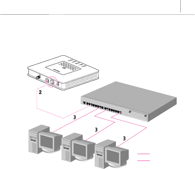
Multiple PCs Connection
The amount of PCs is dependent on the Cable Service Provider. Contact
your Cable Service Provider for further information.
If you want to connect more than one PC to the InfoRanger, you need to prepare
the following additional items:
yAn Ethernet hub or switch of 10/100Mbps transmission speed
yTwisted pair category-3,4,5 crossover cable
yTwisted pair-category-3,4,5 straight-through cables equal to the number of PCs
The specifications of twisted pair category-3,4,5 crossover cables and
straight-through cables are described at Appendix D in detail.
You can connect the InfoRanger to fifteen PCs simultaneously by using
Ethernet port.
If the user needs more than one straight-through cable to connect multiple
PCs to InfoRanger, he/she should prepare the necessary cables by
himself/herself because only one straight-through cable is supplied with
InfoRanger by default.
After preparing all the things to connect additional PCs, do the followings.
1. Turn off all the PCs you want to connect to the InfoRanger.
2. Connect one end of twisted pair category-3,4,5 crossover cable to the Ethernet
port of the InfoRanger. Then, connect the other end of cable to the port of hub.
3-11
3. Connect one end of twisted pair category-3,4,5 straight-through cable to the
port of network interface card installed on PC. Then, connect the other end of
cable to the port of hub.
Figure 3-7 Connecting the InfoRanger to multiple PCs through an Ethernet hub
: crossover
: straight-through
straight-through cable
straight-through cable
Ethernet hub
crossover cable
InfoRanger
straight-through cable
3-12 Chapter 3
Installing the InfoRanger
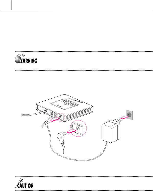
Connecting the Power Adapter
Be sure to connect the power adapter to the InfoRanger only after connecting
other cables.
Do not conn
Do not connDo not conn
Do not conne
ee
ect the InfoRanger
ct the InfoRangerct the InfoRanger
ct the InfoRanger’
’’
’s power adapter before connecting any
s power adapter before connecting anys power adapter before connecting any
s power adapter before connecting any
cables to it.
cables to it.cables to it.
cables to it. It can cause serious damage to the equipment.
Connect one end of the power adapter to DC 12V
jack of the InfoRanger and the
other end to a wall outlet as follows.
Figure 3-8 Connecting the power adapter
Use the power adapter supplied with the InfoRanger only. Using other type
of power adapter can cause critical damage to the InfoRanger.
3-13
Inspecting Cable Connection
The following diagram shows the correct cable connections.
Single PC Connection
Figure 3–9 Cable connection in case of a singal PC connection
The above diagram is showing the case of connecting the PC to Ethernet
port of InfoRanger. The case of connecting the PC to USB port of
InfoRanger is identical.
PC Power adapter
Ethernet cable
(straight-through)
Cable outlet Coaxial cable
InfoRanger
Cable TV service provider
3-14 Chapter 3
Installing the InfoRanger
Multiple PCs Connection
Figure 3-10 Cable connection in case of multiple PCs connection
PC
straight-through cable
straight-through cable
straight-through cable
Ethernet hub
crossover cable
InfoRanger
Coaxial cable
Cable outlet
Power adapter
Cable TV service provider
PC
PC

4-1
Chapter 4 Using the InfoRanger
This chapter explains features of the LEDs and the connectors of the InfoRanger.
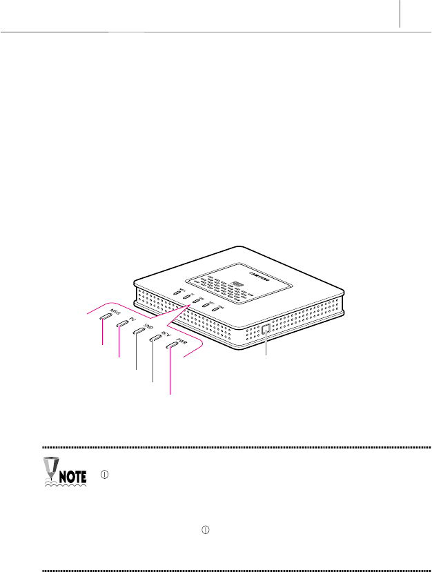
Front View
There are 4 LED indicators lights on the front side of the InfoRanger.
Figure 4-1 Front view of the InfoRanger
When you connect the power adapter to the InfoRanger, a green light is on
LED first, and the InfoRanger processes Self diagnosis Î Initialization for
receiving Î Initialization for sending Î Registering modem and
Authentificating services. While these processes are running, the RCV LED
and SND LED blinks. When this process is complete and the InfoRanger
operates normally, the LED, RCV LED, and SND LED light and remain
green, and PC LED starts blinking. After you connect the Ethernet cable to
the Ethernet port of InfoRanger, the PC LED also turns on steady green.
Reset switch
PWR LED
RCV LED
SND LED
PC LED
MSG LED
4-2 Chapter 4
Using the InfoRanger
The simple meaning of each LED is as follows:
LED Green
Indicates that the power is provided to InfoRanger normally
RCV Indicates InfoRanger is locked, initialization process, Receiving Data
SND Indicates InfoRanger is locked, initialization process, Sending Data
PC Indicates Ethernet link status is fine
LED (POWER LED)
☞When the power is provided to the InfoRanger’s, the green light turns on in
LED. The LED is turned off when the power is not provided to the
InfoRanger.
Color Description
ON Power is provided
Green OFF No Power
RCV LED (RECEIVE LED)
☞The green RCV LED blinks during modem initialization, which means
scanning a downstream (receiving) channel. When the scanning is complete,
the green RCV LED remains continuously lit as long as the modem is locked
on the channel. The RCV LED is turned off when the modem stops working.
The green RCV LED blinks fastly to indicate the modem is receiving data
through the cable network.
Color Description
ON Channel Locked
Green Blinking Low speed : Channel scanning,
Fast speed : Receiving data
4-3
SND LED (SEND LED)
☞The green SND LED blinks during initialization (channel ranging) for
transmitting data (upstream). When ranging is complete, the green SND LED
turns green and remains continuously lit. The SND LED is turned off when
the modem stops working. The green SND LED blinking fastly when the
modem is sending data.
Color Description
ON Ranging Locked
Green Blinking Low Speed : Channel ranging
Fast Speed : Sending Data
PC LED
☞The PC LED lights green and blinks when the InfoRanger comes online and
turns on when the Ethernet link between the PC and InfoRanger is normal.
The PC LED turns off when the Ethernet link goes offline.
Color Description
Blinking Online
ON Link OKGreen
OFF Offline
If the SND LED, RCV LED and the PC LED are off while you are using
the InfoRanger, check to see if the coaxial cable and the Ethernet
cable/USB cable are not connected to the Cable connector and
Ethernet port/USB port properly.
4-4 Chapter 4
Using the InfoRanger
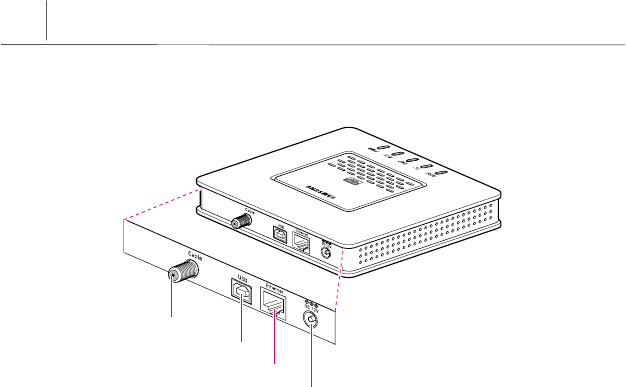
Rear View
Figure 4-2 Rear View of the InfoRanger
DC Input Terminal
☞This is an input terminal, which provides DC 12V to the InfoRanger through
the power adapter.
Reset Switch
☞This is used to initialize the modem.
Ethernet Port
☞The InfoRanger supports up to 40Mbps to download data and also up to
10Mbps to upload data with this Ethernet port. This port is connected to the
network interface card installed on PC or a hub or a switch if it is connected
to multiple PCs using the Ethernet cable.
Cable Connector
Ethernet Port
USB Port
DC Input Terminal

4-5
USB Port
☞This is a USB port with supports up to 12Mbps. This port is connected to the
USB port of PC.
Cable Connector
☞This is used to connect the coaxial cable to the cable outlet or the cable
splitter.


A-1
Appendix A Troubleshooting
Appendix A explains the most common and frequent problems that may occur
while you are using the InfoRanger and suggests how to solve these problems. If
you can not solve the problem with the method described in this Appendix, please
refer to the Technical Support page at the end of this manual or contact the
retailer where the InfoRanger was purchased.
Cannot connect to the Internet service.
- Check to see if the cables are connected correctly.
- If PC LED is off, check the Ethernet interface card installed on
PC and the USB port of PC.
☞ Please refer to the manual of Ethernet interface card.
- Check to see if PC runs normally.
- Check to see if TCP/IP protocol is installed on PC.
- Check to see if the specification of RJ-45 Ethernet cable or USB
cable, which is used for connecting the Ethernet interface card
installed on PC or USB port of PC, is suitable.
☞ Please refer to Appendix D.
- Make sure the cable TV service provider uses two-way cable
communication.
The LED is not turned on even though the power
adapter is connected.
- Check to see if the wall outlet where the power adapter is
connected.
- Make sure that the power adapter is the one supplied with the
InfoRanger.
- Pull out the power adapter from the DC input terminal and
connect it again in about 10 seconds later.
Problem
Solution
Problem
Solution
A-2 Appendix A
Troubleshooting
All LEDs on the side panel of the InfoRanger are
not turned on.
- Check to see if the power adapter is connected to the wall outlet
and DC input terminal of the InfoRanger.
- Check the wall outlet where the power adapter is connected.
- Check to see if the coaxial cable and Ethernet cable are not
connected to the Cable connector and Ethernet port properly.
PC LED is not turned on even though the cable is
connected to the Ethernet port or USB port.
- Check to see if the cable is connected properly to the Ethernet
interface card equipped in PC or the USB port of PC.
- Check the Ethernet interface card equipped in PC or USB port
of PC.
☞ Please refer to the manual of Ethernet interface card.
- Check to see if PC runs normally.
- Check to see if TCP/IP protocol is installed on PC.
- Check to see if the specification of RJ-45 Ethernet cable or USB
cable, which is used for connecting the Ethernet interface card
installed on PC or USB port of PC, is suitable.
☞ Please refer to Appendix D.
Cannot connect to the network after rebooting the
PC in Windows 2000 environment when using
Ethernet port of InfoRanger.
- Pull out the Ethernet cable from the Ethernet port of
InfoRanger and connect it again to get the new IP address.
Problem
Solution
Problem
Solution
Problem
Solution


B-1
Appendix
B
Product Specifications
Item Specification
Ethernet 10/100Mbps, RJ-45 1 port (6 ft.)
Interface USB 12Mbps, USB 1 port (6 ft.)
Operating 32°F to 104°F
Temperature Storage -13°F to 158°F
Downstream 90 ~ 858MHz
Frequency Upstream 5 ~ 42MHz
Downstream 256QAM : 64QAM
Modulation Upstream 16QAM : QPSK
Downstream 64QAM (30Mbps), 256 QAM (40Mbps)
Data rate Upstream QPSK (5Mbps), 16QAM (10Mbps)
Downstream 6MHz
Channel spacing
/ bandwidth Upstream 200KHz, 400KHz, 800KHz, 1.6MHz, 3.2MHz
Downstream RS (128,122) / Trellis
FEC Upstream RS (Programmable)
Downstream 64QAM : 5.056941Msps
256QAM : 5.360537Msps
Symbol rate
Upstream 160K, 320K, 640K, 1280K, 2560Ksps
Downstream 64QAM : 6-bits
256QAM : 8-bits
Bits per symbol
Upstream QPSK : 2-bits
16QAM : 4-bits
Downstream -15 ~ +15dBmV
Level range Upstream QPSK : +8 ~ +58dBmV
16QAM : +8 ~ +55dBmV
B-2 Appendix B
Product Specifications
Item Specification
Carrier to noise ratio 64QAM : >23.5dB @ BER < 10-8
256QAM : >30dB @ BER < 10-8
Security DES decryption / encryption
Size 1.52 (W) x 7.12 (D) x 6.12 (H) (″))
Physical dimension Weight 2.42lb (InfoRanger + Adapter)
AC AC 120V, 60Hz
Power supply DC +7.5V, 1.0A
Regulatory Agency Approval FCC, UL / CUL, CE
Table B-1 Specifications of the InfoRanger


C-1
Appendix C Glossary
10BASE-T
A 10BASE-T is a version of Ethernet using category 3,4,5 cable interface.
Cable modem
A cable modem is a device connected to your computer that enables you to
receive and request information from the Internet over your local cable TV line.
Cable modems are designed to enable peak connection speeds over 100 times
faster than traditional dial-up connections.
Cable splitter
A cable splitter is a metal interface that accepts single input and divides it into
multiple outputs.
Coaxial cable
A coaxial cable is an electrical cable that contains two separate wires. One wire is
solid and the other is a tube. The solid wire is inside the tube, both wires have the
same center point, or axis. Cable TV companies for distributing video signal
typically use it.
DOCSIS (Data Over Cable Service Interface Specification)
DOCSIS defines interface requirements for cable modems involved in high-speed
data distribution over cable television networks. The certified cable modem
project also provides cable modem equipment suppliers with a fast, market-
oriented method for obtaining cable industry acknowledgment of DOCSIS
compliance and has resulted in high-speed modems being certified for retail sale.

C-2 Appendix C
Glossary
Downloading
Downloading is the transfer of data from a server to your computer's hard disk.
You can use your browser or an FTP program to download files to your computer.
When you're retrieving your email, you're downloading your email to your
computer.
E-mail (Electronic mail)
An e-mail is a message, usually text, transmitted over the Internet and sent from
one person to another (although you can also send an e-mail to a large number of
e-mail addresses (mailing list)).
Ethernet
Ethernet is one of the standard specifications for LAN connection. In the Ethernet
configuration, computers are connected with the same axle cable or twisted pair
cable that compete for network access using CSMA/CD method. Data is
transmitted at a maximum speed of 100Mbps.
The representative cables that can be used for Ethernet connection are of three-
types such as 10BASE-5, 10BASE-2, 10BASE-T. InfoRanger uses 10BASE-T
cable.
Hub
A hub is a communication device used to connect several devices and share
resources with the computers on network. It retransmits the signal that is sent by
a device and transmits the received signal dividing it.
Internet
Internet is:
1. The worldwide system of linked networks that is capable of exchanging mail
and data through a common addressing and naming system based on TCP/IP
protocols. (Internet)
2. Any group of linked networks capable of exchanging electronic mail and data
using a common protocol. (internet)

C-3
IP address
An IP address is defined as IP protocol and a 32-bit address, assigned to the host
using TCP/IP. All resources of Internet have their own number, IP address that is
marked as decimal system. The address consists of a network part, optional
subnet part and host part.
LAN (Local Area Network)
A LAN is a network used for relatively small area (single-story or small building)
as an Ethernet and token-ring network. LAN makes it possible for users to
send/receive e-mail and share resources such as files, printers and modems. The
bigger companies connect their own LAN with the Internet to allow users to
connect with resources outside the LAN.
NIC (Network Interface Card)
A NIC is a hardware device that translates electronic signals between a computing
device's native network hardware and the transmission media.
MAC (Media Access Control) address
A MAC address is the physical address of a devices connected to a network such
as network interface card. MAC address is expressed by 6byte colon-separated
hexadecimal numbers.
OSI 7-Layer model
OSI 7-Lay model is a method of describing the relationships between network
protocols by grouping them according to the communication functions the
protocols provide. The OSI model defines 7 distinct categories (Layers) that act
successively on data as it makes its way between the user and the transmission
media.

C-4 Appendix C
Glossary
Protocol
A protocol is, in networking, a specification of the data structures and algorithm
necessary to accomplish a particular network function.
RJ-45
A RJ-45 is a connector used with Ethernet and Token Ring devices that looks like
a telephone jack but has eight wires instead of four or six.
TCP/IP (Transmission Control Protocol / Internet Protocol)
TCP/IP is one of the network protocols used mainly on LAN. When data is
transmitted via network, data is divided into packets. IP transmits the data
packets from one place to another. And TCP manages the data flow and confirms
the correctness of data packets.
Twisted pair
A twisted pair is a cable made up of a pair of insulated copper wires wrapped
around each other to cancel the effects of electrical noise.
USB
USB (Universal Serial Bus) is a new BUS specification, which is an answer to
connectivity for the PC architecture. It is a fast, bi-directional isochronal, low-cost,
dynamically attachable serial interface that is consistent with the requirements of
the PC platform. It supports up to 127 physical devices, and its transfer rate
assures up to 12Mbps.

D-1
ETHERNET ETHERNET
2000mm ± 40mm
RJ-45 RJ-45
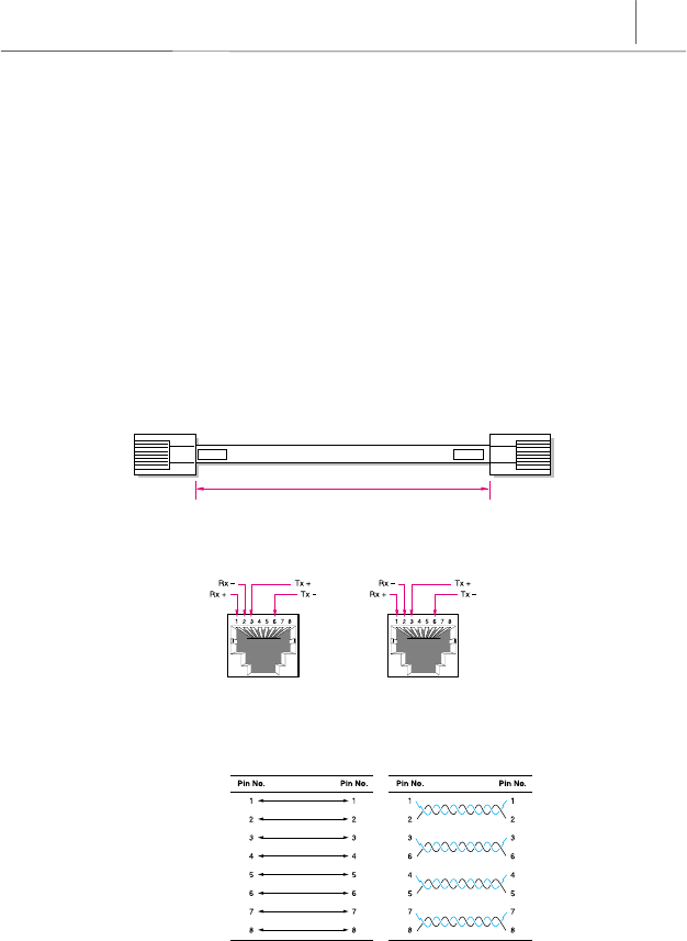
Appendix D Cable Specifications
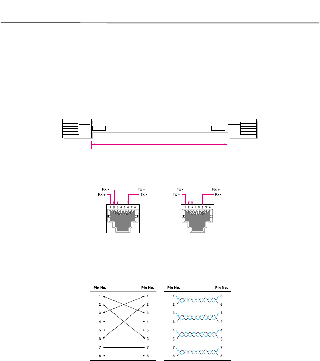
RJ-45 Ethernet Cable
Twisted pair category-3,4,5 straight-through cable
The following RJ-45 Twisted pair category-3,4,5 straight-through cable is used to
connect the Ethernet port of the InfoRanger and the network interface card
installed on PC.
Cable
Figure D-1 Provided Straight-through cable with RJ-45 connectors
Connector
Figure D-2 Pin connections of the straight-through cable
Pin connection
Figure D-3 Pin Signals of the straight-through cable
< Pin Configuration > < Actual Pin Connections >
D-2 Appendix D
Cable Specifications
ETHERNET ETHERNET
2000mm ± 40mm
RJ-45 RJ-45
Twisted pair category-3,4,5 crossover cable
The following RJ-45 Twisted pair category-3,4,5 crossover cable is used to
connect the Ethernet port and the network devices such as a hub or a switch.
Cable
Figure D-4 Crossover cable with RJ-45 connectors
Connector
Figure D-5 Pin Signals of the crossover cable
Pin connection
Figure D-6 Pin connections of the crossover cable
< Pin Configuration > < Actual Pin Connections >
D-3
Red(V
BUS
)
Black(Ground) Green(D +)
White(D
-
)
1.8m
A
A
B
B
C
C
C
C
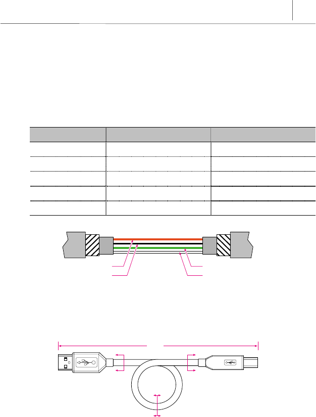
USB Cable
The following USB cable is used to connect the USB port of the InfoRanger and
the USB port of the PC.
USB Connector Termination Data
Contact Number Signal Name Typical wiring Assignment
8VBUS Red
2D- White
3 D+ Green
4 GND Black
Shell Shield Drain Wire
Figure D-7 USB Connector Termination
Cable
Figure D-8 USB Cable
D-4 Appendix D
Cable Specifications
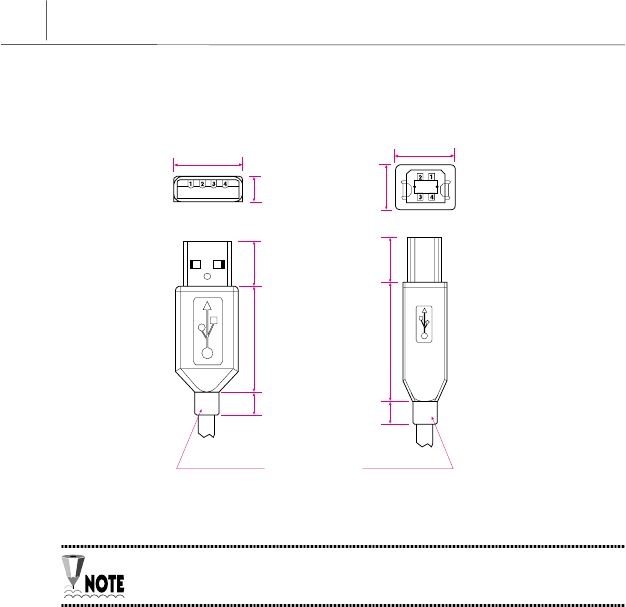
15.7 11.5
7.5
12.0
27.0
9.0
Optional Molded
Strain Relief
Detail A - A
(Series "A" Plug) Detail B - B
(Series "B" Plug)
12.0
27.0
9.0
10.5
Connector
Figure D-9 Pin Signals of the USB cable
All dimensions are in millmeters (mm) in this page.

Technical Support
SAMSUNG offers the highest level of customer service in the industry. Friendly
and knowledgeable customer service is available as follows through our web site
or your service provider.
yGeneral information about the product
ySupport when problems arise
yFAQs
Samsung Electronics Co.,Ltd.
Samsung Telecommunication America, Inc.
1601 East Plano Parkway Suite 150
Plano, TX 75074
Phone : 1-888-987-HELP (4357)
Fax : 1-972-761-7501
URL : www.samsungtelecom.com