Samsung Electronics Co SCS-26UC4 Indoor Base Station Transceiver System User Manual
Samsung Electronics Co Ltd Indoor Base Station Transceiver System
Manual

UbiCell User Guide _
User Menual
Model : SCS-26UC4

2_ © SAMSUNG Electronics Co., Ltd.
Federal Communication Commission Interference Statement
This equipment has been tested and found to comply with the limits for a Class B digital device, pursuant to Part 15 of the FCC
Rules. These limits are designed to provide reasonable protection against harmful interference in a residential installation. This
equipment generates, uses and can radiate radio frequency energy and, if not installed and used in accordance with the
instructions, may cause harmful interference to radio communications. However, there is no guarantee that interference will not
occur in a particular installation. If this equipment does cause harmful interference to radio or television reception, which can be
determined by turning the equipment off and on, the user is encouraged to try to correct the interference by one of the following
measures:
• Reorient or relocate the receiving antenna.
• Increase the separation between the equipment and receiver.
• Connect the equipment into an outlet on a circuit different from that to which the receiver is con-nected.
• Consult the dealer or an experienced radio/TV technician for help.
FCC Caution: To assure continued compliance, (example - use only shielded interface cables when connecting to computer
or peripheral devices). Any changes or modifications not expressly approved by the party responsible for compliance could void
the user’s authority to operate this equipment.This device complies with Part 15 of the FCC Rules. Operation is subject to the
following two conditions: (1) This device may not cause harmful interference, and (2) this device must accept any interference
received, including interference that may cause undesired operation
FCC RF Radiation Exposure Statement:
This equipment complies with FCC RF radiation exposure limits set forth for an uncontrolled environment. This equipment should
be installed and operated with a minimum distance of 20 centimeters between the radiator and your body.This transmitter must
not be co-located or operating in conjunction with any other antenna or transmitter.
UbiCell User Guide _
SAFETY CONCERNS
The purpose of the Safety Concerns section is to ensure the safety of users and prevent property damage.
Please read this document carefully for proper use.
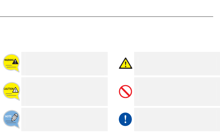
Conventions/Symbols
Warning
Provides information or instructions that
the reader should follow in order to
avoid personal injury or fatality.
Caution
Indication of a general caution.
Caution
Provides information or instructions that
the reader should follow in order to
avoid a service failure or damage to the
system.
Restriction
Indication for prohibiting an action for a
product.
Note
Indicates additional information as a
reference.
Instruction
Indication for commanding a
specifically required action.
4_ © SAMSUNG Electronics Co., Ltd.
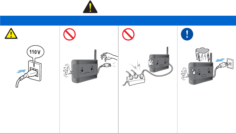
Warning
WARNING
Power
Insert power cord
tightly and fully into the
outlet.
Failure to do so may
cause fire.
Do not touch the
UbiCell or power plug
with wet hands.
Failure to do so may
cause electric shock.
Do not connect many
devices to a single
outlet.
Failure to do so may
cause electric shock.
Pull out the power plug
when the UbiCell is not
used for a long time or
bad weather condition.
Failure to do so may
cause fire or electric
shock.
UbiCell User Guide _
Installation/Maintenance
Do not use or
keep flammable
spray or materials
near the UbiCell.
Failure to do so
may cause fire or
explosion.
Do not install in
humid or dusty
area and near a
heating devices
(heater or light for
cigarette). Install in
the place well
ventilated.
Failure to do so
may cause fire or
electric shock.
Do not put
instruments that
contain water
such as vases,
cups, cosmetics,
and medicines, or
small metals near
the UbiCell.
Moisture in the
UbiCell can cause
a fire and electric
shocks.
Do not put heavy
materials on the
UbiCell.
Failure to do so
may cause the
damage to the
parts of the
UbiCell or fire.
Turn off the power
and unplug the
power cable, and
then contact the
service center if
unusual sound,
smell, or smoke
comes out.
Failure to do so
may cause fire or
electric shock.
6_ © SAMSUNG Electronics Co., Ltd.
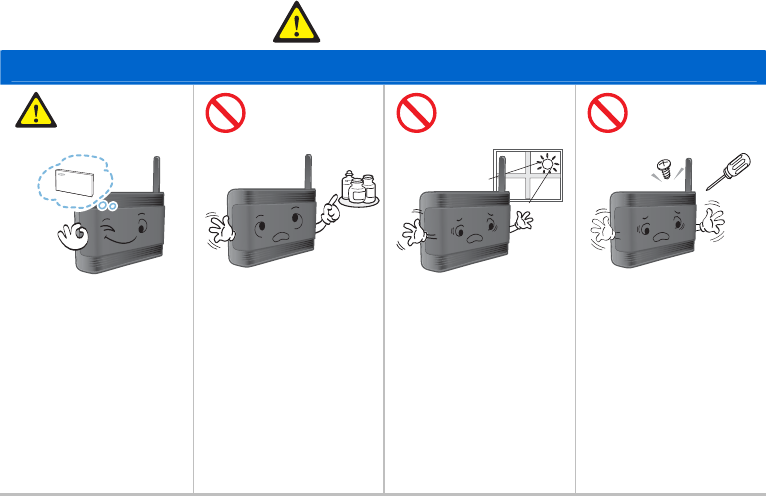
Caution
CAUTION
Installation/Maintenance
Accurately install and
properly use the
product according to
the manual.
This is to prevent
malfunctions and
reductions in product
lifetime.
Do not spray water
directly or do not use
chemical solvents such
as wax, benzene,
alcohol, thinner,
mosquito spray,
aerosol, lubricant, and
detergent.
Failure to do so may
cause the damage to
the product.
Do not install the
UbiCell on an unstable
surface or near the
direct rays of sunlight.
It may cause severe
damage to the parts of
the UbiCell, and your
UbiCell may not work
properly.
Do not separate, repair
or remodel the UbiCell
arbitrarily.
If a repair is needed,
please contact where
the UbiCell was
purchased or call the
Service Center.
UbiCell User Guide _
Installation/Maintenance
Do not place the
product on unstable
support and always be
in an upright position.
This is to protect the
product from falling and
damage from the rise of
inside temperature.
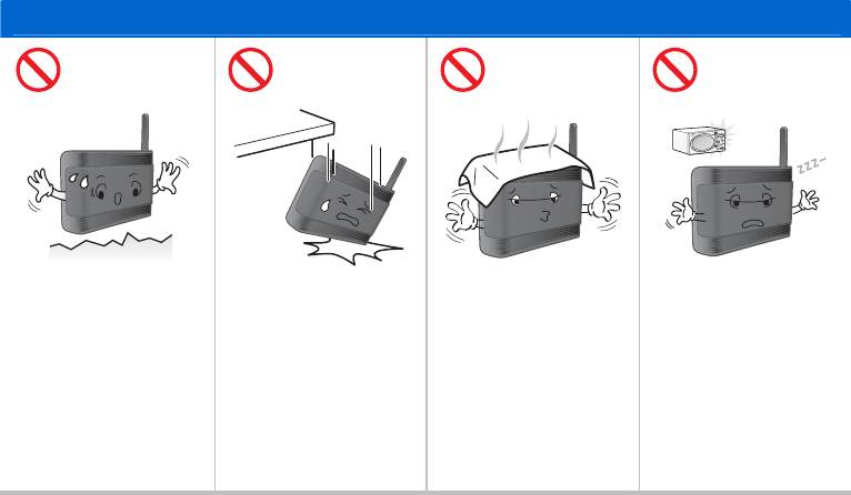
Do not give a shock to
the UbiCell.
The UbiCell can be
damaged.
Do not cover the
UbiCell.
Doing so may cause
product malfunction
resulting from the rise of
inside temperature.
Do not install the
UbiCell near the
products which release
electromagnetic waves
such as microwaves,
hair driers or vacuum
cleaners.
If they are too close,
GPS signal can not be
normally received.
8_ © SAMSUNG Electronics Co., Ltd.
Installation/Maintenance
Clean the UbiCell with a
soft and dry cloth when
cleaning.
Failure to do so may
cause the damage to
the product.
Check the maximum
length of the cable
and install it near the
router.
Failure to do so may
cause malfunction of
this product.
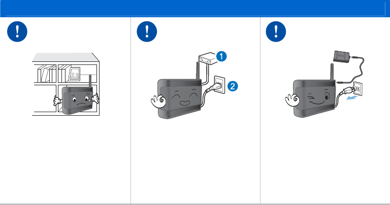
The UbiCell must be
placed more than 50 cm
apart from the other
LAN devices.
RF signal interference
may have a bad effect
on the other LAN
devices.
Please use a refined
accessory and a
charger provided or
activated by Samsung
Electronics.
The use of another
accessory and a
charger may cause the
critical damage to the
product.
UbiCell User Guide _
Installation/Maintenance
Install the product in an area with
good ventilation. Install the
UbiCell at a distance of more
than 30 cm from the walls or
other products.
Not doing so may cause product
malfunction resulting from the rise
of inside temperature.
Ethernet cable connector (RJ-45)
should be plugged before
plugging a DC power cable.
Not doing so may cause product
malfunction.
When detaching the GPS
antenna from the UbiCell to
receive superior GPS signal,
connect extension cable to GPS
antenna after pulling out the
power plug.
Failure to do so may cause the
damage to the product.
10_ © SAMSUNG Electronics Co., Ltd.
Installation/Maintenance
GPS antenna detached from the
UbiCell always should be located
indoors.
If not, GPS antenna can be
damaged, or cannot normally
receive GPS signal.
If the UbiCell does not work for a
long time, check the state of LED
and call customer service.
This is to prevent malfunctions
and reductions in product lifetime.
The UbiCell should be registered
first.
Your UbiCell will not be able to
function if the instruction is
violated.
UbiCell User Guide _
TABLE OF CONTENTS
SAFETY CONCERNS 1
Conventions/Symbols .............................................................................................3
Warning...................................................................................................................4
Caution ...................................................................................................................6
PREPARATION 13
Congratulations!....................................................................................................13
About This Guide ..................................................................................................13
What’s in the box ..................................................................................................14
Names and Functions of each part.......................................................................15
LED.................................................................................................................................................................15
Connector.......................................................................................................................................................16
Registering your UbiCell.......................................................................................19
OVERVIEW 20
삭제됨: 1
삭제됨: 2
삭제됨: 4
삭제됨:
1
삭제됨: 1
1
삭제됨: 1
1
삭제됨: 1
2
삭제됨: 1
3
삭제됨: 1
3
삭제됨: 1
4
삭제됨: 1
7
삭제됨:
1

12_ © SAMSUNG Electronics Co., Ltd.
INSTALLING YOUR UBICELL 21
TROUBLESHOOTING 25
ANNEX A 27
Product Specifications ..........................................................................................27
삭제됨:
1
삭제됨:
2
삭제됨:
2
삭제됨: 2
5
UbiCell User Guide _
PREPARATION
Congratulations!
The UbiCell ensures that you and your family have reliable wireless telephone service while in your home
or small business.
You only have to install the UbiCell in your home or small business, and register.
The UbiCell will be functioned normally through the UbiCell Manager (UCM).
About This Guide
This user guide provides instructions for the use of the UbiCell. Please take the time to make sure of this
guide to become familiar with the operation of your UbiCell and the benefits this new UbiCell can provide.
Keep this guide handy. You may need to look up instructions for infrequently used features.
14_ © SAMSUNG Electronics Co., Ltd.
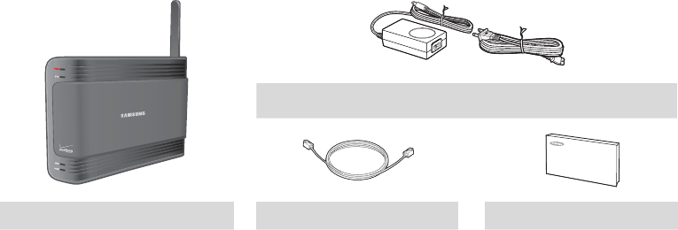
What’s in the box
After purchasing this product, check if the items below are all included in the package.
If any item is missing or damaged, contact your dealer:
Power Supply and Cord
UbiCell Ethernet Cable User Guide
UbiCell User Guide _
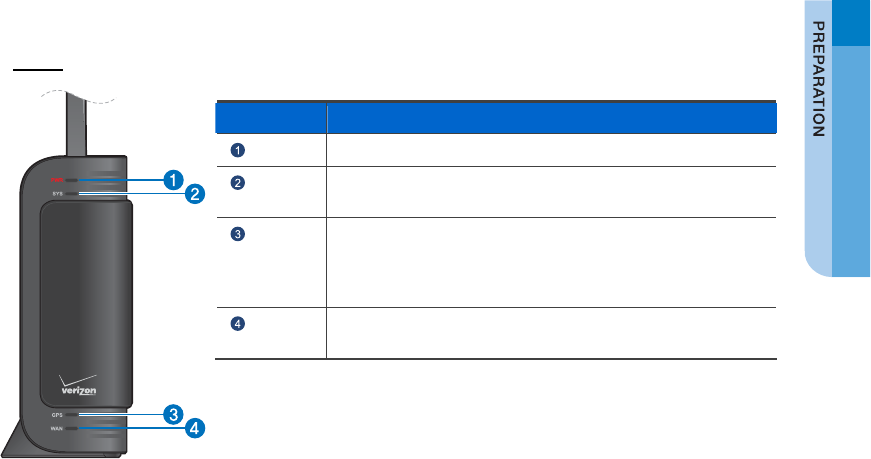
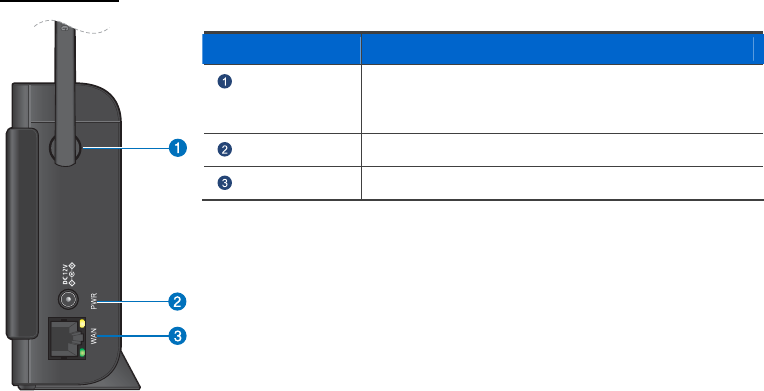
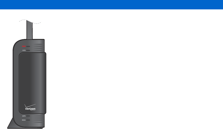
Names and Functions of each part
The UbiCell is very simple. On one end it has connectors for power and LAN.
On the other end the UbiCell has four LED indicators to let you know its status.
LED
Name Description
PWR When powering on the UbiCell, it turns blue.
SYS When the UbiCell normally works, It turns blue.
When the alarm occurs, it turns red.
GPS When GPS signal is normally received, it turns blue.
When the internal GPS antenna is not able to detect a stable
GPS signal and cannot validate accurate time and location
information, it turns red.
WAN When the Ethernet cable is normally connected, it turns blue.
When there is data traffic, it turns blinking blue.
16_ © SAMSUNG Electronics Co., Ltd.
Connector
Name Description
Antenna Provides omni-directional transmission and reception
of signals between the UbiCell and communicating
mobile station.
PWR Connects the power cable.
WAN Connects the Ethernet cable.
UbiCell User Guide _
Using the GPS Antenna detached from the UbiCell as an External GPS Antenna
NOTE
If the UbiCell is installed in places where GPS signals cannot be received,
detach the GPS antenna from the UbiCell. Extension cable for GPS antenna is sold
separately.
Power off
When detaching the GPS antenna from the UbiCell to receive superior GPS signal, connect
extension cable to GPS antenna after pulling out the power plug.
The GPS antenna detached from the UbiCell
The GPS antenna detached from the UbiCell always should be located indoors.
The GPS antenna detached from the UbiCell must be laid in a horizontal position, as close to a window as
possible. Laying it on a window is ideal. To be certain of keeping the antenna horizontal,
you may wish to tape it down, but do not use duct tape. The window should not have metal blinds,
nor metallic solar film.
The extension cable that is connected between the UbiCell and detached GPS antenna is 7 meters (about
23 feet) long, providing plenty of flexibility in locating both it and the UbiCell.
18_ © SAMSUNG Electronics Co., Ltd.
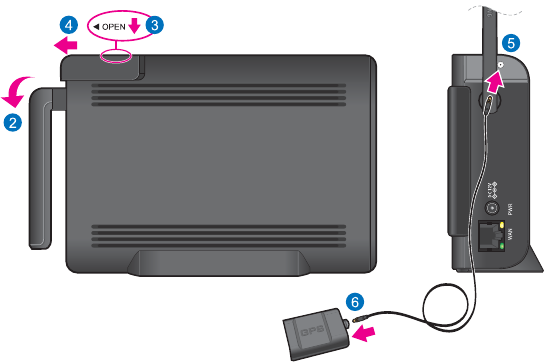
1) Turn off the base station.
2) Rotate the antenna down to provide access to the GPS antenna’s protective cover.
3) Firmly press down on the Open button (top of station)
4) Slide the protective cover back to expose the internal GPS mini-coax connector.
5) Connect and secure the GPS antenna to the exposed port by using the GPS cable.
6) Connect and secure the terminal end of the same mini-coax cable to the port on the GPS antenna.
GPS Antenna
UbiCell User Guide _
Registering your UbiCell
Before installing your UbiCell you need to register.
Registering
Your UbiCell will not be able to function if the instruction is violated.
Your UbiCell should be registered first.
20_ © SAMSUNG Electronics Co., Ltd.
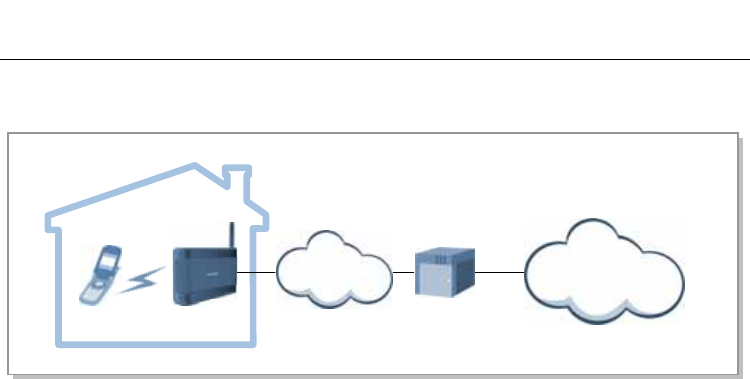
OVERVIEW
The UbiCell is a system that performs the radio interface with Mobile Stations (MS), and exchanges radio
subscriber data and signal data with the MSs under CDMA2000 standards.
MS
ISP
UbiCell
Provider’s
Network
Security Gateway
Home or Office
UbiCell User Guide _
INSTALLING YOUR UBICELL
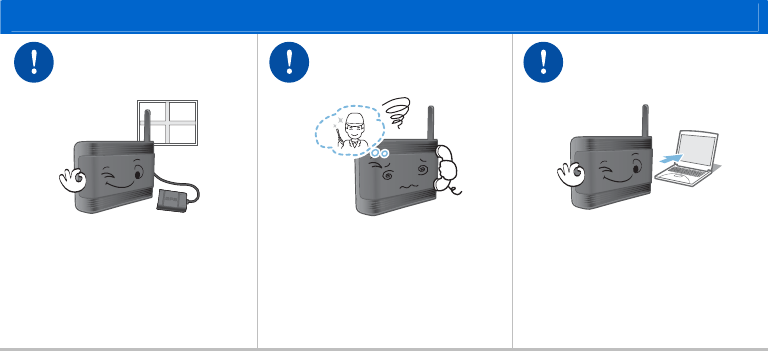
If possible, place the UbiCell in a high location such as on top of a book shelf or tall cabinet.
For best results place the UbiCell in a room with a window.
Make sure your DSL modem or cable modem and broadband router are on and working properly.
When your UbiCell is operating, you had better stay at a distance of more than 20 cm from the UbiCell.
Installation Environment
Refer to the ‘Environment Standard’ of ‘ANNEX’ for the conditions of the environment which
make the UbiCell normally work.
Installing your UbiCell
1) Your UbiCell always should be in an upright position.
2) Install the UbiCell at a distance of more than 30 cm from the walls or other products.
3) The adjustable antenna rotates only 180 degrees.
Rotating it beyond that angle may damage the antenna.
22_ © SAMSUNG Electronics Co., Ltd.
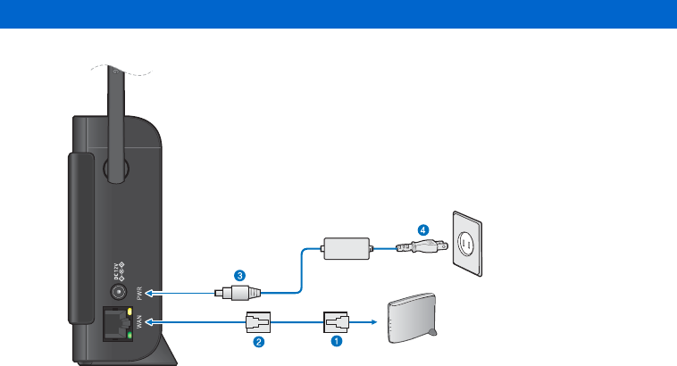
Connecting Ethernet Cables and Power
1) Connect one end of the included Ethernet cable to an open port on the modem.
2) Connect the other end to the WAN port located at the rear of the UbiCell.
3) Plug the power supply connector into the PWR connector located at the rear of the UbiCell.
Power Supply
Ethernet Cable
Power Cord
Modem
UbiCell User Guide _
4) Insert one end of the power cord into the power supply and then plug the other end into an available
power outlet.
Ethernet Cable
1) Check the maximum length of the cable and install it near the router.
2) Ethernet cable connector (RJ-45) should be plugged before plugging a DC power cable.
Connecting the power
1) Please use a refined accessory and a charger provided or activated by Samsung
Electronics.
2) Use only the power supply and cord that are included in the package.
Using any other power source may damage the UbiCell.
24_ © SAMSUNG Electronics Co., Ltd.
Checking the LED
The ‘PWR’ LED on the front of the UbiCell should lit up blue when power is
connected normally. Over the next few minutes the ‘WAN’ LED, the ‘GPS’
LED, and the ‘SYS’ LED should all lit up blue. (If after 10 minutes any of the
LEDs is not lit up, or is lit up red, see the ‘Troubleshooting’ instructions on the
next page.)
That’s all there is to it. You can now make and receive calls with your existing
handset using the UbiCell.
UbiCell User Guide _
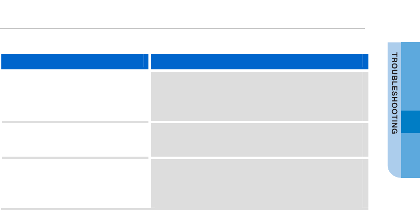
TROUBLESHOOTING
In the unlikely event that you have problems, check the following:
Trouble Solution
The PWR LED is not lit - Make sure that one end of the power cord is securely
connected to an active outlet and that the other end is
properly connected to the power supply.
- Make sure the power supply connector is securely inserted
into the rear PWR connector on the back of the UbiCell.
The SYS LED lights up red The UbiCell was unable to register.
A red System LED indicates a system error was detected.
Contact Samsung Customer Service.
The WAN LED lights up red - A red light indicates that the WAN port is receiving power
but has not detected a valid Ethernet connection.
- Confirm that both ends of the Ethernet cable are securely
plugged into the WAN port on the UbiCell and into an open
port on the router(or modem).

26_ © SAMSUNG Electronics Co., Ltd.
Trouble Solution
The GPS LED still does not light up
blue 10 minutes after plugging-in the
UbiCell
- The internal GPS antenna is either unable to obtain or
having difficulty obtaining a GPS signal.
- Move the UbiCell a location with fewer surrounding
obstructions. The new location should be in a more open
area and closer to a window, if possible.
- If relocation does not resolve the issue, detach the GPS
antenna from the UbiCell to use it as an external GPS
antenna.
- Make sure the power is properly configured and securely
connected to the rear of the UbiCell.
- If the preceding fails, remove the power cord from the wall
outlet, and then remove the power supply connector from
PWR connector at the rear of the UbiCell for at least 10
seconds.
- Reconnect the power supply connector to the PWR
connector, plug the power cord into the wall outlet.
This allows the UbiCell to initiate its startup sequence where
it detects the Ethernet connection, GPS signal,
and communication with the system.
If the above suggestions did not correct the problem, or you encounter a problem that is not listed here,
you can get additional assistance by calling Samsung customer service.
UbiCell User Guide _
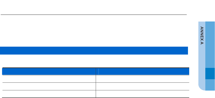
ANNEX A
Product Specifications
The specifications of the UbiCell are as follows:
Capacity
The capacity of the UbiCell is described as follows:
Category Specification
Maximum Number of Frequencies 1 FA
Sector Omni
Maximum Number of Channels 4 CEs
28_ © SAMSUNG Electronics Co., Ltd.
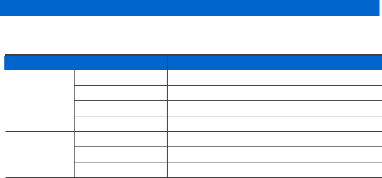
Transmitter/Receiver Specification
The specification of the transmitter and receiver of the UbiCell is described as follows:
The items that are not included in the following table should meet the IS-95A/B, IS-2000 standard.
Item Specification
Tx Frequency 1,930~1,990 MHz or 869~894 MHz
Channel Bandwidth 1.25 MHz
Power 50 mW/carrier
Transmission
Modulation QPSK
Rx Frequency 1,850~1,910 MHz or 824~849 MHz
Channel Bandwidth 1.25 MHz
Reception
Sensitivity -119 dBm (1.9 G) or -117 dBm (800 M)
UbiCell User Guide _
Unit Specification
The specification of the UbiCell is described as follows:
Category Specification
Size (H × W × D, mm) 144.0 ×204.4 × 42.2
Weight (g) 955 (580+ 375[adapter & cables]) ± 40
Power
The specification of the UbiCell power is described as follows.
The UbiCell meets the power safety criterion defined in UL60950-1 and EN60950-1.
Category Specification
Input Voltage AC 110 V
Voltage Variation Range (Tolerable error of
commercial electric power source) 100~250 VAC