Samsung Electronics Co SFG-D1100 5G Outdoor CPE User Manual Installation Manual
Samsung Electronics Co Ltd 5G Outdoor CPE Installation Manual
UserManual.wiki
>
Samsung Electronics Co
>
SFG-D1100 User Manual
>
Installation Manual
Contents
1.
Installation Manual
2.
Safety & Warranty Guide
Installation Manual
Navigation menu
Upload a User Manual
Namespaces
Wiki Guide
HTML
PDF
Info
Views
User Manual
Discussion / Help
Navigation
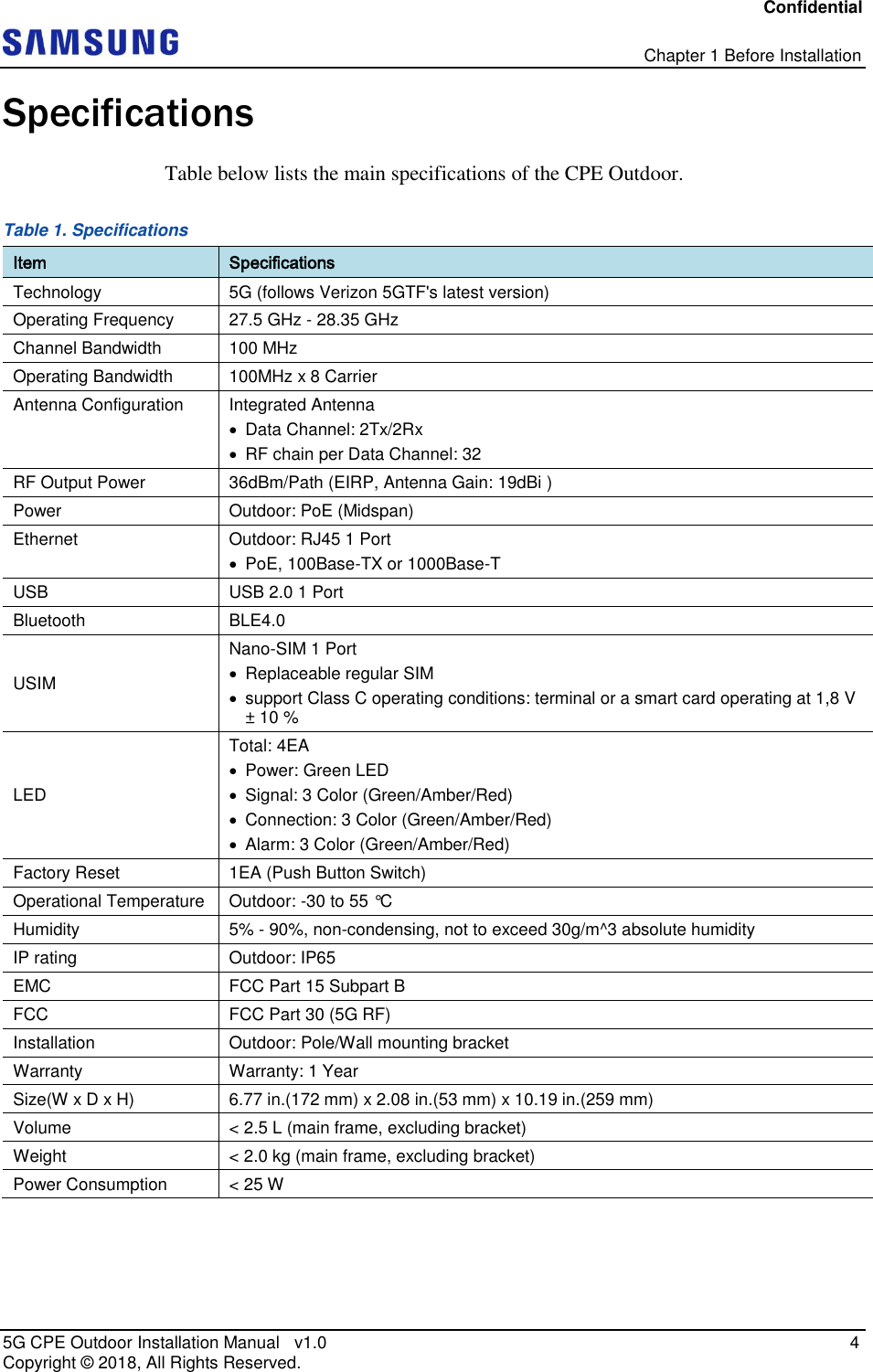
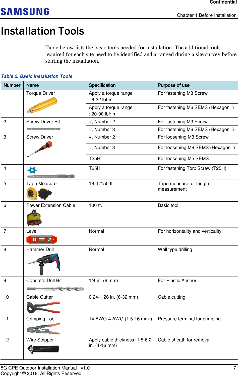
![Confidential 5G CPE Outdoor Installation Manual v1.0 1 Copyright © 2018, All Rights Reserved. Chapter 1 Before Installation This chapter introduces CPE Outdoor and describes the items that you should know before installation. System View and External Interface This section provides the pictorial view of the CPE Outdoor and its interfaces. CPE Outdoor View Figure below depicts the physical structure of the CPE Outdoor. Figure 1. CPE Outdoor View [Bottom View] [Top View] [Left View] 10.19 (259) 2.08 (53) Unit: in. (mm) [Right View] [Rear View] [Front View] 6.77 (172) 2.52 (64)](https://usermanual.wiki/Samsung-Electronics-Co/SFG-D1100.Installation-Manual/User-Guide-3755218-Page-13.png)
![Confidential Chapter 1 Before Installation 5G CPE Outdoor Installation Manual v1.0 2 Copyright © 2018, All Rights Reserved. Figure 2. CPE Outdoor View(include Cable Cover) [Bottom View] [Top View] [Left View] 13.71 (348.4) 2.08 (53) Unit: in. (mm) [Right View] [Rear View] [Front View] 6.86 (174.4) 2.52 (64)](https://usermanual.wiki/Samsung-Electronics-Co/SFG-D1100.Installation-Manual/User-Guide-3755218-Page-14.png)
![Confidential Chapter 1 Before Installation 5G CPE Outdoor Installation Manual v1.0 3 Copyright © 2018, All Rights Reserved. CPE Outdoor External Interface Figure below depicts the external interface structure of the CPE Outdoor. Figure 3. CPE Outdoor External Interface Ground Terminal LAN [Bottom View]](https://usermanual.wiki/Samsung-Electronics-Co/SFG-D1100.Installation-Manual/User-Guide-3755218-Page-15.png)
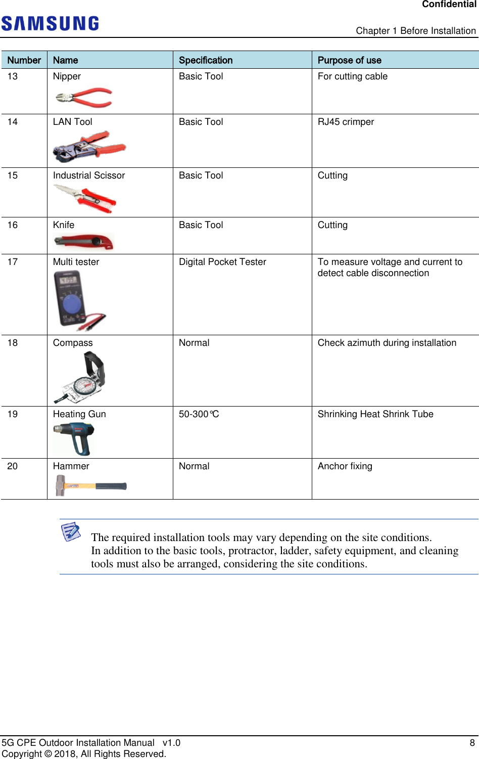
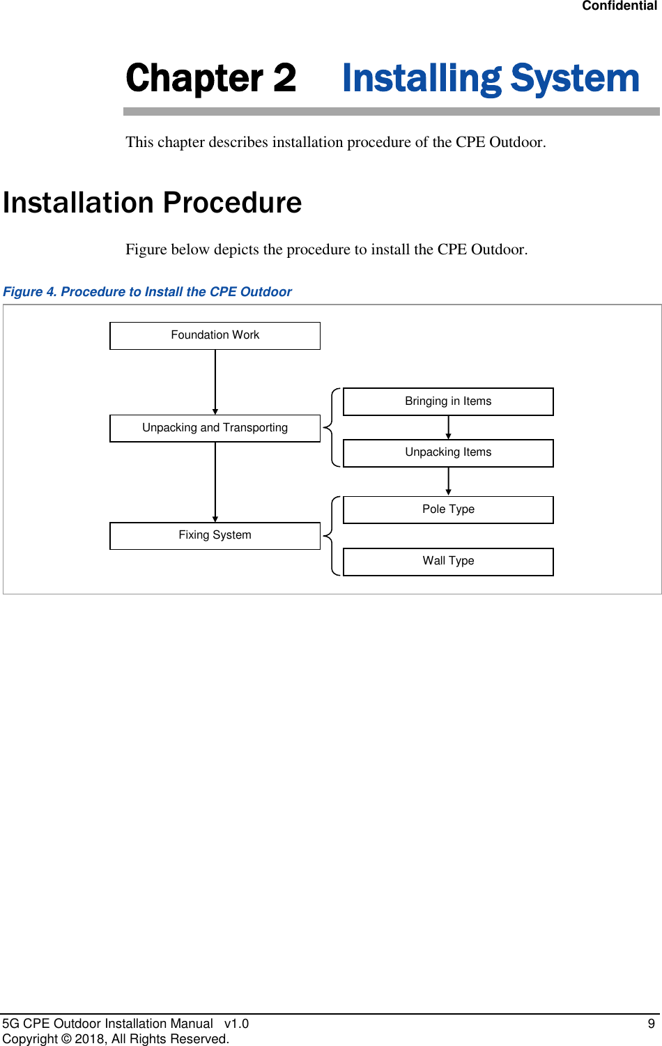
![Confidential Chapter 2 Installing System 5G CPE Outdoor Installation Manual v1.0 10 Copyright © 2018, All Rights Reserved. System Arrangement A minimum distance must be secured around the CPE Outdoor, in each direction for installation and maintenance. Figure below depicts the minimum distance that must be secured for pole type installation of the CPE Outdoor. Figure 5. CPE Outdoor Arrangement Pole type Installation Figure below depicts the minimum distance that must be secured for wall type installation of the CPE Outdoor. Figure 6. CPE Outdoor Arrangement Wall type Installation Unit: in. (mm) [Top View] [Front View] ≥ 16 (400) ≥ 8 (200) ≥ 8 (200) W: 6.86 (174.4) H: 13.71 (348.4) 4.88 (124) ≥ 32 (800) ≥ 16 (400) Unit: in. (mm) [Top View] [Front View] ≥ 16 (400) ≥ 8 (200) ≥ 8 (200) W: 6.86 (174.4) H: 13.71 (348.4) 4.88 (124) ≥ 32 (800) ≥ 16 (400)](https://usermanual.wiki/Samsung-Electronics-Co/SFG-D1100.Installation-Manual/User-Guide-3755218-Page-22.png)
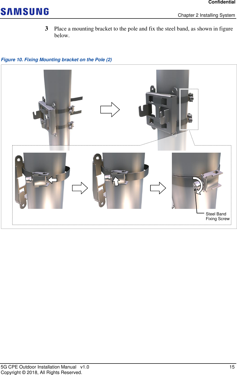
![Confidential Chapter 2 Installing System 5G CPE Outdoor Installation Manual v1.0 17 Copyright © 2018, All Rights Reserved. Figure 12. Fixing CPE Outdoor on the Pole Mounting Bracket Fixing System on a Wall Type An CPE Outdoor can be fixed on wall using a mounting bracket. This section details the procedures for fixing the mounting bracket on the wall and fixing the CPE Outdoor on the bracket. To mark on the wall 1 Ensure that the items mentioned in below table are available. Table 6. Tools for Marking Category Description Working Tools Tape Measure Permanent Maker Level M5 SEMS(T25H) Mounting Bracket_Hook Groove M5 SEMS(T25H) [Left View] [Right View]](https://usermanual.wiki/Samsung-Electronics-Co/SFG-D1100.Installation-Manual/User-Guide-3755218-Page-29.png)
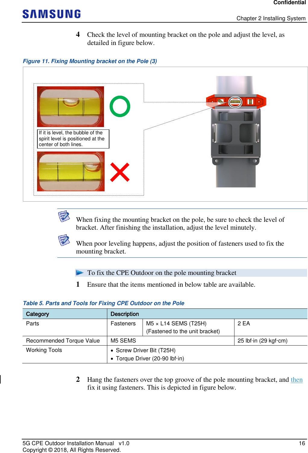
![Confidential Chapter 2 Installing System 5G CPE Outdoor Installation Manual v1.0 18 Copyright © 2018, All Rights Reserved. Perform leveling test before drilling by referring to System Leveling, to ensure the positions marked are horizontal or vertical. If the result shows the marked positions are not horizontal or vertical, modify the marking positions. When the position to place the system is determined, place the system on that position and then mark the positions where anchor bolts are to be fixed. This reduces marking error range. 2 Check the distance between the location for fixing the CPE Outdoor and the anchor bolt hole, as shown in figure below. Figure 13. CPE Outdoor Marking Dimensions for Wall Type 3 Place the mounting bracket on the fixing location, check the level status using a level, and adjust the level of the bracket assembly. 4 If the level status is normal, mark the anchor bolt holes on the wall. This is detailed in figure below. Unit: in. (mm) : Anchor Bolt Hole [Rear View] 2.49 (64) 3.69 (93.8)](https://usermanual.wiki/Samsung-Electronics-Co/SFG-D1100.Installation-Manual/User-Guide-3755218-Page-30.png)
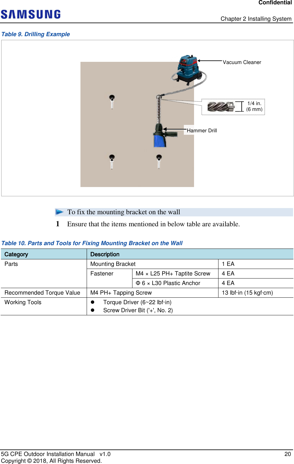
![Confidential Chapter 2 Installing System 5G CPE Outdoor Installation Manual v1.0 19 Copyright © 2018, All Rights Reserved. Figure 14. Marking Wall Type To drill the anchor holes 1 Ensure that the items mentioned in below table are available. Table 7. Tools for Drilling Category Description Woking Tools Hammer Drill Drill Bit (1/4 inch) Vacuum Cleaner Table 8. Anchor Bolt Drill Bits and Hole Depth Category Anchor Bolt Drill Bits Hole Depth CPE Outdoor Φ 6 1/4 in. (6 mm) 1.4 in. (35 mm) 2 Drill anchor holes at the marked points. Remove dust from the holes using a vacuum cleaner. [O] * Remove the debris from the drilled hole. [Anchor Hole Cross Section] 35 mm (1.4 in) [X] 1/4 in. (6 mm) 2.49 (64) Unit: in. (mm)/ Marking Point If it is level, the bubble of the spirit level is positioned at the center of both lines. 3.69 (93.8)](https://usermanual.wiki/Samsung-Electronics-Co/SFG-D1100.Installation-Manual/User-Guide-3755218-Page-31.png)
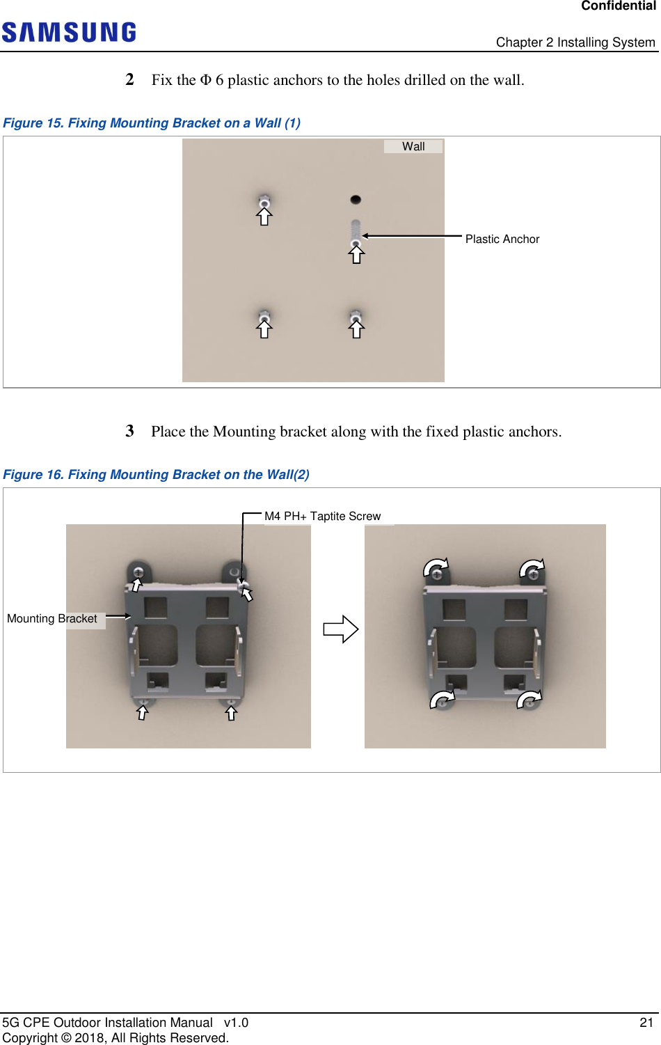
![Confidential Chapter 2 Installing System 5G CPE Outdoor Installation Manual v1.0 22 Copyright © 2018, All Rights Reserved. To fix the CPE Outdoor on the wall 1 Ensure that the items mentioned in below table are available. Table 11. Parts and Tools for Fixing CPE Outdoor on the Wall Category Description Parts Fasteners M5 × L14 SEMS (T25H) (Fastened to the unit bracket) 2 EA Recommended Torque Value M5 SEMS 25 lbfin (29 kgf·cm) Working Tools Screw Driver Bit (T25H) Torque Driver (20-90 lbf·in) 2 Hang the fasteners over the top groove of the wall mounting bracket, and then fix it using fasteners. This is depicted in figure below. Figure 17. Fixing CPE Outdoor on the Wall Mounting Bracket M5 SEMS(T25H) Mounting Bracket_Hook Groove M5 SEMS(T25H) [Left View] [Right View]](https://usermanual.wiki/Samsung-Electronics-Co/SFG-D1100.Installation-Manual/User-Guide-3755218-Page-34.png)