Samsung Electronics Co SIP005AFS30 ARTIK-0530 User Manual addendum for Full Modular Approval
Samsung Electronics Co Ltd ARTIK-0530 addendum for Full Modular Approval
Contents
- 1. User Manual_20160929_v1 - 06_ARTIK530DevBoardUserGuide_Draft_0928
- 2. User Manual_20161006_v2 - 06_SIP007AFS00_manual_final
- 3. User Manual addendum for Full Modular Approval
User Manual addendum for Full Modular Approval
Page 1 of 5
ARTIK 530(s) User Manual and HOST INSTALLATION MANUAL
Reference
Samsung Module Model: SIP005AFS30
FCC ID: A3L-SIP005AFS30
IC ID: 649E-SIP005AFS30
The Samsung ARTIK 530(s) is a certified transmitter module approved under FCC ID: A3L-SIP005AFS30
and ISED Canada certification number 649E-SIP005AFS30.
Instructions for installation of this module when using the onboard uFL connectors can be found in this
document and provided that those instructions are followed the certification of the module can be
leveraged for the combination of host and system. If using an on-board trace to connect to an antenna,
either directly or via an on-board rf connector, please refer to the limited modular approval installation
guide.
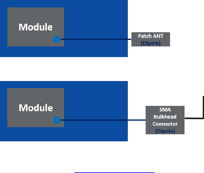
The Full Modular Approval (FMA) covers the module installed such that the U.FL connectors for the
ZigBee and Wi-Fi/Bluetooth antennas on the module connect directly to the antennas via an u.FL-to-RP-
SMA connector.
The FMA covers the antenna configuration listed below:
• Option 1: Patch Antenna direct connected to SoM (see the Molex 146153-0050 peak gain in the
section below)
• Option 2: Use SMA Mounted Antenna direct connected to SoM (see the Taoglas GW.71.5153
peak gain in the section below). The connector should be reverse gender or thread.
The u.FL-to-RP-SMA connector specification and its loss are listed below:
• Vendor: Data Alliance, LLC. (https://www.data-alliance.net)
• Antenna Cable: SKU: RSf30mmUFL, u.FL to RP-SMA Female: 1 inch cable
One end has a U.FL connector and the other end has a RP-SMA female connector.
• Cable Thickness: 1.13mm: Thin, flexible

Page 2 of 5
• Attenuation Per Foot:
o at 900 MHz: 0.23 db/ft
o at 2.4 GHz: 0.39 db/ft
o at 3.4GHz: 0.47 db/ft
o at 5.1-5.8GHz: 0.643 db/ft
• The actual measurement of the cable loss:
Frequency
Cable loss
WiFi
2400MHz
0.37
5180MHz
0.57
5320MHz
1.6
5600MHz
0.87
5800MHz
1.0
Zigbee
2400MHz
0.37
The Full Modular Approval covers these 2 antenna:
1. Molex 146153-0050
2. Taoglas GW.71.5153
Connection of an antenna directly to the U.FL connectors on the module, is covered by the certification
provided that the following requirements are met:
1. The antenna type must be a dipole or patch antenna;
Antenna type
2.4/5GHz Balanced Flex Antenna
Antenna peak gain
(WiFi and Zigbee)
+2.56 dBi(2484 MHz)
+3.04 dBi (5180 MHz)
+3.49 dBi (5320 MHz)
+4.59 dBi (5600 MHz)
-4.87 dBi (5800 MHz)
Antenna type
Diploe 2.4GHz/5.8GHz RP-SMA Antenna
Antenna peak gain
(WiFi and Zigbee)
+3.2 dBi(2484 MHz)
+4.8 dBi (5180 MHz)
+4.7 dBi (5320 MHz)
+4.3 dBi (5600 MHz)
+4.0 dBi (5800 MHz)
Page 3 of 5
2. The gain of the antenna, which includes any cable loss between the uFL connector on the
module and the antenna, must not exceed
1
the following:
Frequency
Maximum patch antenna gain
(antenna peak gain - cable loss)
(Molex 146153-0050)
Maximum dipole antenna gain
(antenna peak gain - cable loss)
(Taoglas GW.71.5153)
WiFi
2400MHz
2.56-0.37=2.19
3.2-0.37=2.83
5180MHz
3.04-0.57=2.47
4.8-0.57=4.23
5320MHz
3.49-1.6=1.89
4.7-1.6=3.1
5600MHz
4.59-0.87=3.72
4.3-0.87=3.43
5800MHz
4.87-1.0=3.87
4.0-1.0=3.0
Zigbee
2400MHz
2.56-0.37=2.19
3.2-0.37=2.83
All other requirements in the installation instructions must be followed. These include:
• Labeling the host device with “Contains FCC ID: A3L-SIP005AFS30 ” and “Contains IC ID: 649E-
SIP005AFS30”;
• Ensuring that the end user does not have the ability to remove the antennas, or if they do using
a unique antenna connector to ensure only an equivalent antenna can be used;
• Host devices must be considered as mobile equipment for RF exposure classification. This
means that the host device should not be operating within 20cm of people and would typically
be a desktop, wall mounted or similar device.
If the installation conditions cannot be met then additional certification requirements apply. Please
contact Samsung at support@samsung.com to determine if your installation conditions can be covered
through a Class 2 Permissive Change to the modular approval or need to be addressed as a system level
(host + module) approval.
Instruction to integrator for the dipole antenna
For the dipole the user/integration manual, according to RSS-GEN, must give direction to the integrator
that the end product manual needs to follow the following:
For license-exempt equipment with detachable antennas, the user manual shall also contain the
following notice in a conspicuous location:
This radio transmitter [649E-SIP005AFS30] has been approved by Innovation, Science and
Economic Development Canada to operate with the antenna types listed below, with the maximum
permissible gain indicated. Antenna types not included in this list that have a gain greater than the
maximum gain indicated for any type listed are strictly prohibited for use with this device.
1. Molex 146153-0050
1
These values are lower than those detailed for connection to the PCB trace as they account for the cable loss
between module and PCB trace and the loss of the PCB trace
Antenna type
2.4/5GHz Balanced Flex Antenna
Page 4 of 5
2. Taoglas GW.71.5153
FCC REGULATORY DISCLOSURES
This device complies with Part 15 of the FCC`s Rules. Operation is subject to the following two
Conditions: (1) This device may not cause harmful interference, and (2) This device must accept any
interference received, including interference that may cause undesirable operation.
This equipment has been tested and found to comply with the limits for a Class B digital device,
pursuant to part 15 of the FCC Rules. These limits are designed to provide reasonable protection against
harmful interference in a residential installation. This equipment generates, uses and can radiate radio
frequency energy and, if not installed and used in accordance with the instructions, may cause harmful
interference to radio communications. However, there is no guarantee that interference will not occur
in a particular installation. If this equipment does cause harmful interference to radio or television
reception, which can be determined by turning the equipment off and on, the user is encouraged to try
to correct the interference by one or more of the following measures:
• Reorient or relocate the receiving antenna.
• Increase the separation between the equipment and receiver.
• Connect the equipment into an outlet on a circuit different from that to which the receiver is
connected.
• Consult the dealer or an experienced radio/ TV technician for help.
This equipment complies with FCC radiation exposure limits set forth for an uncontrolled environment.
This equipment should be installed and operated with a minimum distance of 20cm between the
transmitter’s radiating structure(s) and the body of the user or nearby persons.
This module is intended for OEM integration. The OEM integrator is responsible for FCC compliance and
compliance with all applicable regulations including those for modular transmitters 47 C.F.R. 15.212. The
Antenna peak gain
(WiFi and Zigbee)
+2.56 dBi(2484 MHz)
+3.04 dBi (5180 MHz)
+3.49 dBi (5320 MHz)
+4.59 dBi (5600 MHz)
-4.87 dBi (5800 MHz)
Antenna type
Diploe 2.4GHz/5.8GHz RP-SMA Antenna
Antenna peak gain
(WiFi and Zigbee)
+3.2 dBi(2484 MHz)
+4.8 dBi (5180 MHz)
+4.7 dBi (5320 MHz)
+4.3 dBi (5600 MHz)
+4.0 dBi (5800 MHz)
Page 5 of 5
OEM product must comply with all applicable labeling requirements including those contained in 15
C.F.R. 15.19. The OEM is solely responsible for certification and testing and labeling of its own products.
In addition to any independently required labels, the OEM shall also affix to the outside of a device into
which the module is installed a label referring to the enclosed module. This exterior label should be
prepared in a legible font and permanently affixed and using the wording “Contains Transmitter Module
FCCID: A3LSIP005AFS30
The OEM is required to ensure that the end product integrates this module so as to maintain a minimum
distance of 20 cm between the equipment’s radiating structure(s) and the body of the user or nearby
persons. The OEM shall also advise its end user of this requirement as required by applicable rules.
The OEM shall require that the end user of its product be informed that the FCC radio frequency
exposure guidelines for an uncontrolled environment can be satisfied. The OEM shall further inform its
end user that any change or modifications to this module not expressly approved by the manufacturer
will void the warranty and the users’ authority to operate the equipment.
INDUSTRY CANADA REGULATORY DISCLOSURES
INDUSTRY CANADA STATEMENT
This device complies with Industry Canada license-exempt RSS standard(s). Operation is subject to the
following two conditions: (1) This device may not cause harmful interference, and (2) this device must
accept any interference received, including interference that may cause undesired operation.
Cet appareil est conforme avec Industrie Canada exempts de licence standard RSS (s). L'opération est
soumise aux deux conditions suivantes:(1) cet appareil ne peut causer d'interférences, et
(2) cet appareil doit accepter toute interférence, y compris les interférences qui peuvent causer un
mauvais fonctionnement de l'appareil.
INDUSTRY CANADA RADIATION EXPOSURE STATEMENT AND LIMITATIONS ON USE
This equipment complies with IC RSS-102 radiation exposure limits set forth for an uncontrolled
environment. This equipment should be installed and operated with minimum distance 20 cm between
the radiator and your body. This equipment should be installed and must not be co-located or operating
in conjunction with any other antenna or transmitter.
This equipment is restricted to indoor use in the 5.15-5.25 GHz range. This equipment is not able to be
operated at 5600-5650. In the United States and Canada, only Channel 1~11 can be operated and these
channel assignments deal only with the 2.4 GHz range.
The end product must be labeled to display the Industry Canada certification number of the module.
“Contains transmitter module IC: 649E-SIP005AFS30”
Le dispositif d'accueil doivent être étiquetés pour afficher le numéro de certification d'Industrie Canada
du module.
Contient module émetteur IC : 649E-SIP005AFS30.