Samsung Electronics Co SLS-2A00002100 LTE Evolved UTRAN Node-B System User Manual MetroPCS
Samsung Electronics Co Ltd LTE Evolved UTRAN Node-B System MetroPCS
UserManual.wiki
>
Samsung Electronics Co
>
SLS 2A00002100 User Manual
user manual
Navigation menu
Upload a User Manual
Namespaces
Wiki Guide
HTML
PDF
Info
Views
User Manual
Discussion / Help
Navigation


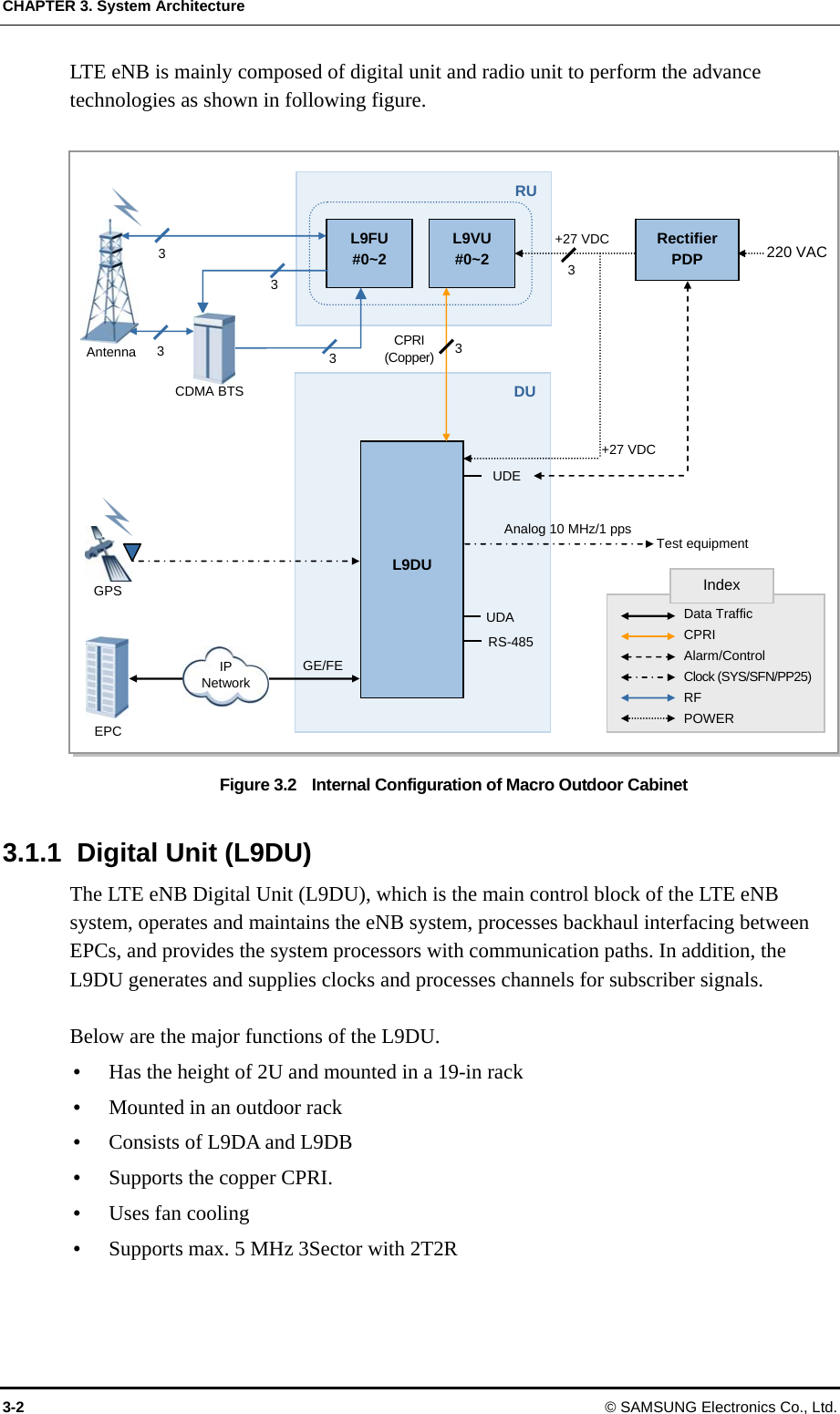
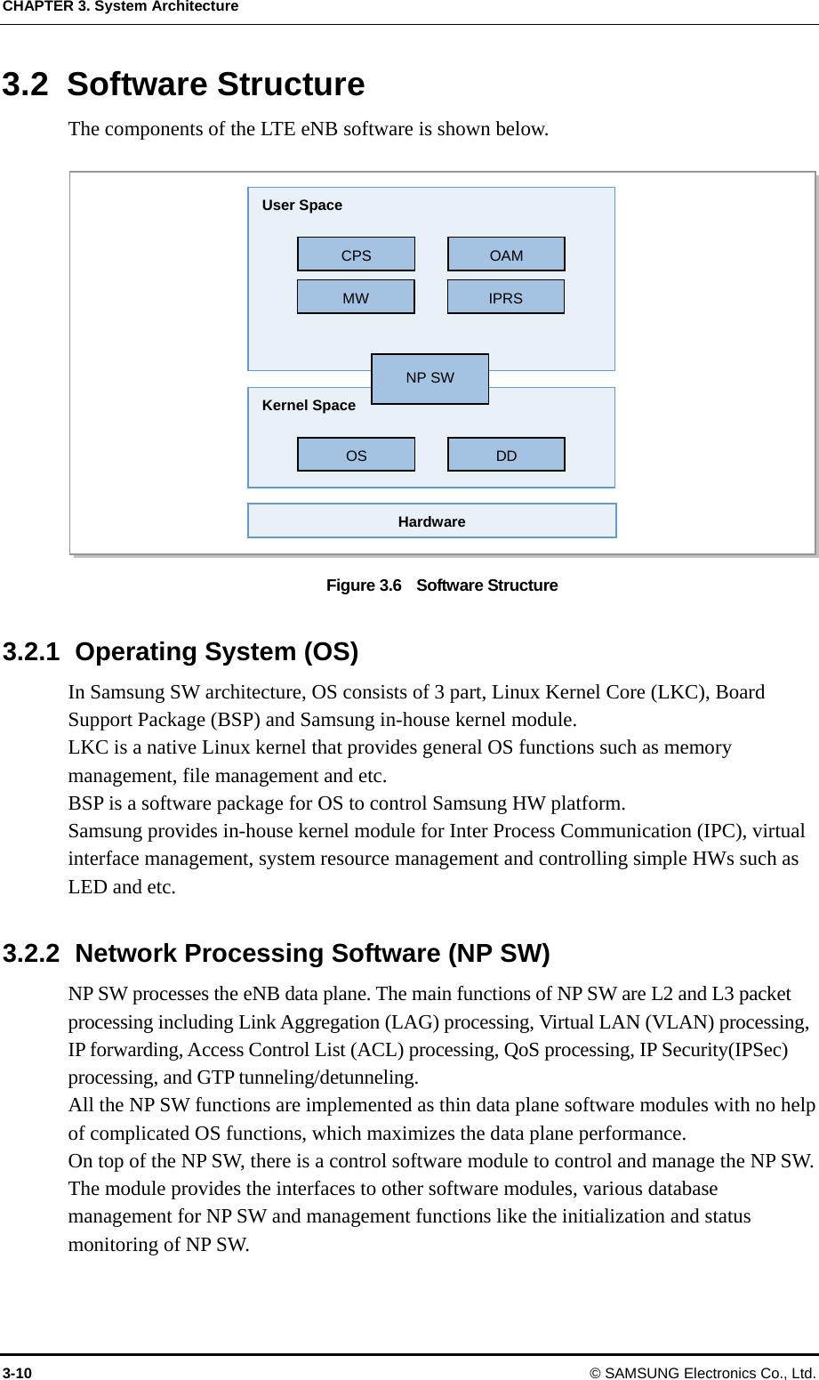
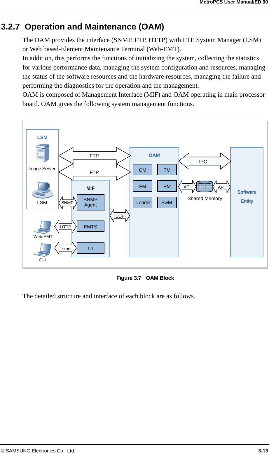
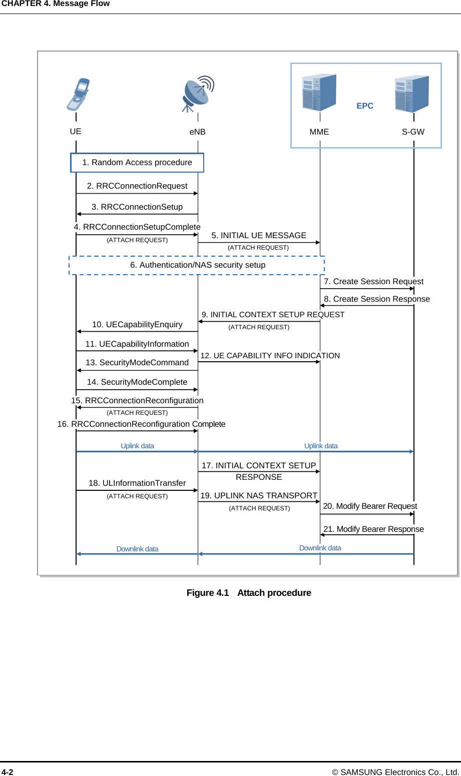
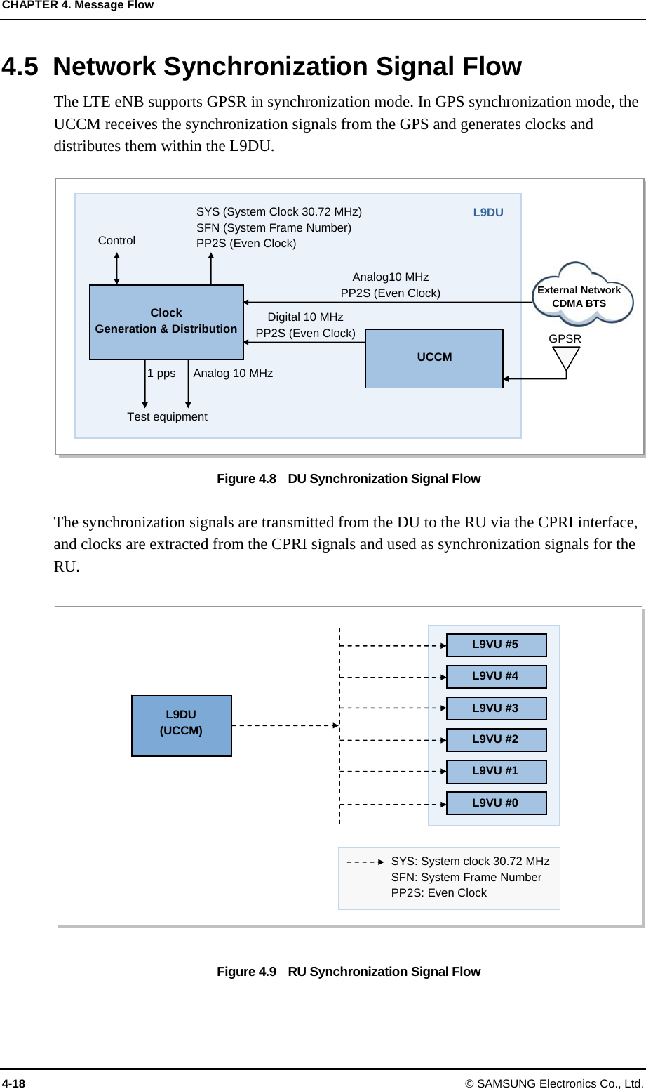
![CHAPTER 3. System Architecture 3-4 © SAMSUNG Electronics Co., Ltd. L9DA Below are the major functions of the L9DA. y Main Controller Function The L9DA, the main processor of the LTE eNB system, is the board which performs the topmost functions in the eNB, and sets up a communication path between the UE and EPC, carries out the Ethernet switch function within the eNB, and carries out the system operation and maintenance functions. In addition, the L9DA manages the status for all hardware/software in the eNB, allocates and manages resources, collects alarms, and reports all status information to the LSM. Also, it initializes the IF FPGA and Ethernet switches to manage boards. y Clock Generation and Distribution Function The L9DA is equipped with the Universal Core Clock Module (UCCM) for receiving GPS signals. The UCCM allows the blocks of the eNB to operate under a synchronized clock system. The UCCM generates analog 10 MHz clocks (for measuring instruments or attendants) and digital clocks [PP2S (even clock), digital 10 MHz] using synchronization signals received from the GPSR and transmits them to the L9DA. The UCCM generates system clocks (30.72 MHz), PP2S (even clock), and System Fame Number (SFN) to synchronize the signals received by a board and then distributes them to the hardware blocks within the system. These clocks are used to maintain internal synchronization in the eNB and operate the system. And, the UCCM also transmits time information and location information through the TOD path. If the UCCM fails to receive GPS signals due to an error during system operation, it carries out the holdover function that supplies the normal clocks that have been provided for a specific period of time. y Network Interface Function The L9DA interfaces directly with the EPC via Gigabit Ethernet or Fast Ethernet. If the network interface is provided directly to the EPC via Ethernet, a total of 4 ports, 2 L9DU optic ports, and 2 copper ports are supported. If necessary, the optic module can be changed to the LC connector type or SC connector type. In case of the copper ports, the cable configuration changes depending on the supported speed and distance. And, if either optic or copper ports are used, the other type of ports is used for the Ethernet path (for example, UDE). y Subscriber Channel Processing Function The L9DA is equipped with the modem which supports the LTE standard physical layer. The L9DA performs OFDMA/SC-FDMA channel processing and DSP processes RLC/MAC. The modem modulates the packet data received from the upper processor and transmits them to the RF part via Common Public Radio Interface (CPRI). In the other direction, it demodulates the packet data received from the RF part, converts them to the format which is defined in the LTE standard physical layer specifications, and transmits them to the upper processor.](https://usermanual.wiki/Samsung-Electronics-Co/SLS-2A00002100/User-Guide-1266043-Page-29.png)