Samsung Electronics Co SLS-BD104Q1 WiMAX / TD-LTE Remote Radio Head User Manual
Samsung Electronics Co Ltd WiMAX / TD-LTE Remote Radio Head
Contents
- 1. Installation Manual
- 2. User Manual
User Manual

Ver.
2600-00ETB9GAA
2.0
Mobile WiMAX/TD-LTE RRH-2WB
Installation Manual

COPYRIGHT
This manual is proprietary to SAMSUNG Electronics Co., Ltd. and is protected by copyright.
No information contained herein may be copied, translated, transcribed or duplicated for any commercial
purposes or disclosed to the third party in any form without the prior written consent of SAMSUNG Electronics
Co., Ltd.
TRADEMARKS
Product names mentioned in this manual may be trademarks and/or registered trademarks of their respective
companies.
This manual should be read and used as a guideline for properly installing and operating the product.
This manual may be changed for the system improvement, standardization and other technical reasons without prior
notice.
If you need updated manuals or have any questions concerning the contents of the manuals, contact our Document
Center at the following address or Web site:
Address: Document Center 3rd Floor Jeong-bo-tong-sin-dong. Dong-Suwon P.O. Box 105, 416, Maetan-3dong
Yeongtong-gu, Suwon-si, Gyeonggi-do, Korea 442-600
Homepage: http://www.samsungdocs.com
©2012 SAMSUNG Electronics Co., Ltd. All rights reserved.

Mobile WiMAX/TD-LTE RRH-2WB Installation Manual
© SAMSUNG Electronics Co., Ltd. I
INTRODUCTION
Purpose
This manual describes how to install the RRH-2WB of TD-LTE Flexible system (SLS-
BD104) which is a multi-mode BS of Mobile WiMAX/TD-LTE, and how to connect cables.
Document Content and Organization
This document consists of 3 Chapters, 6 Annex and Abbreviation, which are summarized as
follows:
CHAPTER 1. Before Installation
This chapter introduces the safety rules that must be understood for installing the RRH-
2WB and describes the block diagram of the RRH-2WB.
CHAPTER 2. Installing System
This chapter describes the procedures to install the RRH-2WB.
CHAPTER 3. Connecting Cables
This chapter describes the procedures to connect the cables to the RRH-2WB installed.
ANNEX A. Sector Antenna Installation
This annex describes cautions and installation procedure of the sector antenna.
ANNEX B. Installing Feeder Cable
This annex describes cautions and allowed radius of curvature when installing feeder line.
ANNEX C. Connector Assembly
This annex describes the procedure of assembling connector.
ANNEX D. Cleaning Optic Connector
This annex describes the procedure of cleaning the optic connector and cleaning tool.

INTRODUCTION
II © SAMSUNG Electronics Co., Ltd.
ANNEX E. Pressure Terminal Assembly
This annex describes the procedure of assembling the pressure terminal.
ANNEX F. Standard Torque
This annex describes the standard torque when assembling the fixing materials.
ABBREVIATION
Describes the acronyms used in this manual.
Conventions
The following types of paragraphs contain special information that must be carefully read
and thoroughly understood. Such information may or may not be enclosed in a rectangular
box, separating it from the main text, but is always preceded by an icon and/or a bold title.
WARNING
Provides information or instructions that the reader should follow in order to avoid
personal injury or fatality.
CAUTION
Provides information or instructions that the reader should follow in order to avoid
a service failure or damage to the system.
CHECKPOINT
Provides the operator with checkpoints for stable system operation.
NOTE
Indicates additional information as a reference.

Mobile WiMAX/TD-LTE RRH-2WB Installation Manual/Ver.2.0
© SAMSUNG Electronics Co., Ltd. III
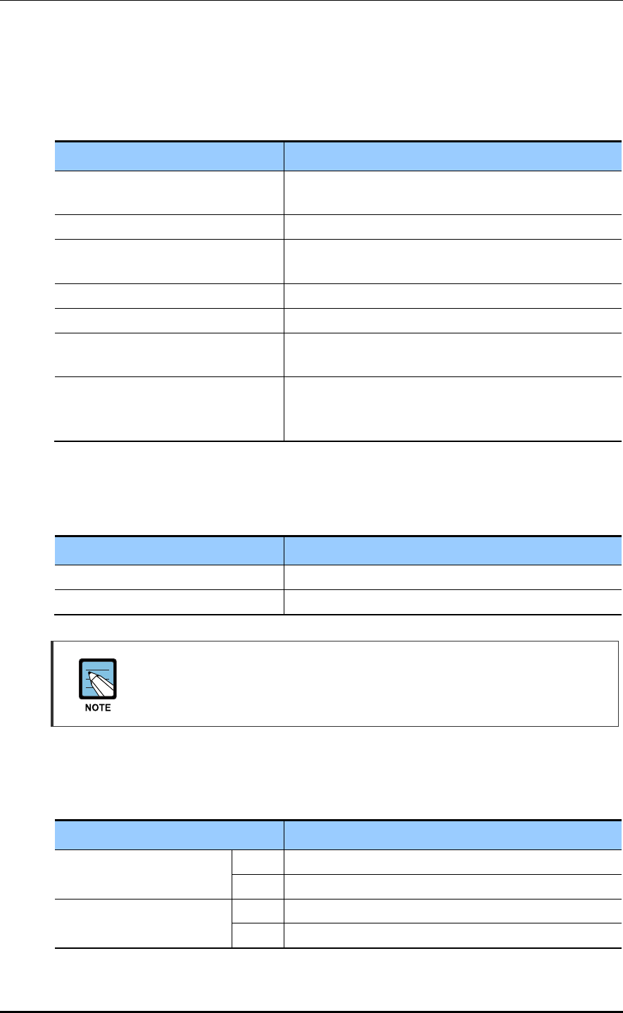
Revision History
VERSION DATE OF ISSUE REMARKS
2.0 06. 2012. - ‘Humidity condition’ was changed. (1.2)
- ‘Table 3.5’~‘Table 3.7’ were changed.
- ‘Cable Connection of RET’ (3.5.2) was added.
- DU configuration was changed. (Figure 3.2, Table 3.7)
1.0 04. 2012. First Version

INTRODUCTION
IV © SAMSUNG Electronics Co., Ltd.
This page is intentionally left blank.

Mobile WiMAX/TD-LTE RRH-2WB Installation Manual
© SAMSUNG Electronics Co., Ltd. V
SAFETY CONCERNS
The purpose of the Safety Concerns section is to ensure the safety of users and prevent
property damage. Please read this document carefully for proper use.
Symbols
Caution
Indication of a general caution
Restriction
Indication for prohibiting an action for a product
Instruction
Indication for commanding a specifically required action

SAFETY CONCERNS
VI © SAMSUNG Electronics Co., Ltd.
Warning
Power and Grounding
Watches, Rings, and Other Metallic Accessories
Do not wear accessories such as watches and rings in order to prevent electrical
shock.
Power Switch Off
Make sure the power switch of power supplier is off when installing the system.
Installing the system with power switch on may cause system damage or fatal
human injury when cables are not correctly connected.
Warning for Connecting the Ground Cable
In cabling, the connection of cables without the connection to the ground cable
may cause the damage of the equipment or the injury of the worker.
Connect the ground cable first.
Installation
Warning for Laser Beam Running through Optical Cables
In the system, the laser beam emitting light runs through the optical cable.
The exposure of the laser beam on worker’s eye may cause serious injury so that
it should be handled with care.
Protection gloves and goggles
Make sure that worker wears protection gloves and goggles to prevent damages
from debris while drilling holes in a wall or ceiling.
WARNING
Mobile WiMAX/TD-LTE RRH-2WB Installation Manual/Ver.2.0
© SAMSUNG Electronics Co., Ltd. VII
Caution
Power and Feeder line
Cautions while Cleaning Power Supply
While cleaning the power supply device, take caution that the device does not
come in contact with alien bodies that may cause power failure.
Handling the Power Cable
- Handling the power cable incorrectly may damage the rack or cause an electric
shock through the cable. Ensure the power switch on the rectifier or the system
is turned off before handling the power cable.
- The fixing materials for power cable must be tightly secured to prevent electrical
accidents.
Power cable
In case of using AWG8 (6 mm2 × 2C) power cable, it is applicable up to 70 m
(299.66 ft). When the distance is 70 m (299.66 ft), followings should be considered.
- Do not rapid ON/OFF (within one second): The voltage loss value caused by the
cable resistance loss is 3 V, and the RRH-2WB could be damaged by the
counter electromotive force caused by the cable inductance.
- The battery’s life could be shorten: The RRH-2WB could be off in spite the
battery remains. (When the battery capacity is designed within one hour)
- Do not use the power cables linked: Using the power cables linked each other,
the loss will be increased.
Precautions for Measuring Insulation Resistance
Since a high voltage is used for measuring insulation resistance, insulation
resistance should not be measured when the system is in operation. Make sure to
only measure the insulation resistance of the appointed part. Other components
such as the system’s internal components and the unit (system frame),
components of the communication cables, units, etc. should not be measured.
Cable Work Sequence
When performing cable work for the system, proceed with the ground work before
any other work to prevent errors occurring due to static electricity and other reasons.
CAUTION

SAFETY CONCERNS
VIII © SAMSUNG Electronics Co., Ltd.
Connection of Feeder Cable Connector
Connecting the feeder cable connector is critical process, so the qualified workers
who finished the related education should perform.
Radius of Curvature of Feeder Line
When installing a feeder line, the radius of curvature of the sections where cables
bent should be larger than the allowed radius of curvature. If the radius of
curvature for the feeder line installation is less than the allowed radius of curvature,
it may affect the performance of the system.
Installation
Cautions while Cleaning the Rack
Make sure that worker does not damage installed cables while cleaning the rack.
System Installation and Access
Only authorized workers are allowed to install or access the system.
Do not Work by Yourself
Worker must not work alone in any key process.
Management of Unused Ports
Cover the unused ports (conduit, cable gland, etc.) with waterproof cap (sealing
cap) to prevent infiltration of foreign material such as dust, moisture, or bug.
Caution When Connecting the Optical Cable
When connecting the optical cable, be careful to keep the cutting section of the
connector core away from dust and foreign substances. If the cable is soiled with
foreign substances, do not blow on the cable to remove them. Make sure to
remove the dust or foreign substances in accordance with the cleaning
instructions provided by the connector manufacturer.
Mobile WiMAX/TD-LTE RRH-2WB Installation Manual/Ver.2.0
© SAMSUNG Electronics Co., Ltd. IX
Finishing Heat Shrink Tube of a Sector Antenna
1) Insert an antenna protection plate to antenna port.
2) Place the heat shrink tube on the connection point and shrink the heat shrink
tube using a heat gun. Avoid aiming the heating gun toward the antenna’s body.
Installing the Antenna
When you install the antenna, the distant and angle between the antenna and
lightning rod must be within the protective angle (left/right side 45° each from the
central axis) to prevent the antenna from lightning damage.
California USA Only
This Perchlorate warning applies only to primary CR (Manganese Dioxide)
Lithium coin cells in the product sold or distributed ONLY in California USA
‘Perchlorate Material-special handling may apply, See
www.dtsc.ca.gov/hazardouswaste/perchlorate.’

SAFETY CONCERNS
X © SAMSUNG Electronics Co., Ltd.
This page is intentionally left blank.

Mobile WiMAX/TD-LTE RRH-2WB Installation Manual
© SAMSUNG Electronics Co., Ltd. XI
TABLE OF CONTENTS
INTRODUCTION I
Purpose .................................................................................................................................................. I
Document Content and Organization..................................................................................................... I
Conventions ........................................................................................................................................... II
Revision History .................................................................................................................................... III
SAFETY CONCERNS V
Symbols ................................................................................................................................................. V
Warning ................................................................................................................................................. VI
Caution ................................................................................................................................................ VII
California USA Only .............................................................................................................................. IX
CHAPTER 1. Before Installation 1-1
1.1 System Configuration and Structure ................................................................................... 1-1
1.2 Specifications ........................................................................................................................ 1-4
1.3 Cautions for Installation ........................................................................................................ 1-6
1.4 Pre-survey .............................................................................................................................. 1-8
1.5 Installation Tools .................................................................................................................... 1-9
CHAPTER 2. Installing System 2-1
2.1 Installing the RRH-2WB ......................................................................................................... 2-1
2.2 Foundation Work ................................................................................................................... 2-2
2.2.1 System Arrangement ............................................................................................................ 2-2
2.2.2 Marking and Drilling .............................................................................................................. 2-3
2.3 Unpacking and Transporting ................................................................................................ 2-4
2.3.1 Importing Items ..................................................................................................................... 2-4
2.3.2 Unpacking Items ................................................................................................................... 2-4
2.4 Fixing the System .................................................................................................................. 2-5
2.4.1 Fixing the Wall Type RRH-2WB ........................................................................................... 2-5
2.4.2 Fixing the Pole Type RRH-2WB ........................................................................................... 2-8

TABLE OF CONTENTS
XII © SAMSUNG Electronics Co., Ltd.
2.4.3 Fixing the Tower type RRH-2WB ........................................................................................ 2-22
2.5 System Leveling ................................................................................................................... 2-31
2.6 Insulation Test ...................................................................................................................... 2-33
CHAPTER 3. Connecting Cables 3-1
3.1 Work Flow for Cabling ........................................................................................................... 3-1
3.2 Cabling .................................................................................................................................... 3-5
3.3 Grounding ............................................................................................................................... 3-7
3.3.1 Grounding the System .......................................................................................................... 3-8
3.4 Power Construction ............................................................................................................. 3-10
3.4.1 Installing the Power Cable .................................................................................................. 3-10
3.5 External Interface Construction .......................................................................................... 3-14
3.5.1 Cable Connection between the DU and the RRH-2WB .................................................... 3-14
3.5.2 Cable Connection of RET ................................................................................................... 3-20
3.5.3 Connection of Feeder Cable ............................................................................................... 3-22
3.6 Installation Test .................................................................................................................... 3-30
ANNEX A. Sector Antenna Installation A-1
A.1 Cautions when Installing a Sector Antenna ........................................................................ A-1
A.2 Sector Antenna Layout ......................................................................................................... A-1
A.3 Sector Antenna Installation .................................................................................................. A-2
ANNEX B. Installing Feeder Cable B-1
B.1 Cautions When Installing Feeder Cable .............................................................................. B-1
B.2 Antenna Feeder Cable Ground ............................................................................................. B-4
B.3 Tower Ground Construction ................................................................................................. B-8
ANNEX C. Connector Assembly C-1
C.1 N type-male (1/2 in. feeder line) ............................................................................................ C-1
C.2 Din type-male (1/2 in. Feeder Line) ...................................................................................... C-6
C.3 Finishing the Connector Connection Part by Tape ............................................................ C-8
C.4 How to Shrink the Heat Shrink Tube .................................................................................... C-9
C.4.1 When Assembling a Connector to the Feeder Line ............................................................ C-9
C.4.2 When Connecting a Connector to another Connector ....................................................... C-11
C.5 Power Connector Assembly ............................................................................................... C-15

Mobile WiMAX/TD-LTE RRH-2WB Installation Manual/Ver.2.0
© SAMSUNG Electronics Co., Ltd. XIII
ANNEX D. Cleaning Optic Connector D-1
D.1 Cleaning Optic Connector ..................................................................................................... D-1
D.2 IBCTM Brand Cleaner .............................................................................................................. D-2
D.2.1 IBCTM Brand Type Cleaner (P/N 9393) ............................................................................... D-2
D.2.2 IBCTM Brand Type Cleaner (P/N 12910) ............................................................................. D-5
ANNEX E. Pressure Terminal Assembly E-1
ANNEX F. Standard Torque F-1
ABBREVIATION I
L ~ V ........................................................................................................................................................ I
LIST OF FIGURES
Figure 1.1 RRH-2WB Configuration ...................................................................................... 1-1
Figure 1.2 RRH-2WB Configuration When the Solar Shield is Assembled ............................. 1-2
Figure 1.3 RRH-2WB External Interface ................................................................................ 1-3
Figure 2.1 Procedure to Install the RRH-2WB ........................................................................ 2-1
Figure 2.2 RRH-2WB Installation Space................................................................................. 2-2
Figure 2.3 RRH-2WB Marking ................................................................................................ 2-3
Figure 2.4 Fixing the RRH-2WB_Wall Type (1) ...................................................................... 2-5
Figure 2.5 Fixing the RRH-2WB_Wall Type (2) ...................................................................... 2-6
Figure 2.6 Fixing the RRH-2WB_Wall Type (3) ...................................................................... 2-7
Figure 2.7 Example of Installing on Wall Mount Pole ............................................................. 2-8
Figure 2.8 Example of Installing on Mono Pole ...................................................................... 2-9
Figure 2.9 Example of Installing on Pole .............................................................................. 2-10
Figure 2.10 Example of Installing on Pole (Detail A, Detail B) ............................................... 2-11
Figure 2.11 Fixing 1 Sector Pole Type RRH-2WB (1) ........................................................... 2-12
Figure 2.12 Fixing 1 Sector Pole Type RRH-2WB (2) .......................................................... 2-13
Figure 2.13 Fixing 1 Sector Pole Type RRH-2WB (3) .......................................................... 2-14
Figure 2.14 Fixing 3 Sector Pole Type RRH-2WB (1) .......................................................... 2-15
Figure 2.15 Fixing 3 Sector Pole Type RRH-2WB (2) .......................................................... 2-16
Figure 2.16 Fixing 3 Sector Pole Type RRH-2WB (3) .......................................................... 2-17
Figure 2.17 Fixing 3 Sector Pole Type RRH-2WB (4) .......................................................... 2-18

TABLE OF CONTENTS
XIV © SAMSUNG Electronics Co., Ltd.
Figure 2.18 Fixing 3 Sector Pole Type RRH-2WB (5) ........................................................... 2-19
Figure 2.19 Fixing 3 Sector Pole Type RRH-2WB (6) ........................................................... 2-20
Figure 2.20 Bolt Specifications for 3 Sector Pole Type RRH-2WB-Examples ....................... 2-21
Figure 2.21 Example of Installing on the Tower .................................................................... 2-22
Figure 2.22 Fixing Tower Type RRH-2WB (1) ....................................................................... 2-23
Figure 2.23 Fixing Tower Type RRH-2WB (2) ....................................................................... 2-24
Figure 2.24 Fixing Tower Type RRH-2WB (3) ....................................................................... 2-25
Figure 2.25 Fixing Tower Type RRH-2WB (4) ....................................................................... 2-26
Figure 2.26 Fixing Tower Type RRH-2WB (5) ....................................................................... 2-27
Figure 2.27 Fixing Tower Type RRH-2WB (6) ....................................................................... 2-28
Figure 2.28 Fixing Tower Type RRH-2WB (7) ....................................................................... 2-29
Figure 2.29 Fixing Tower Type RRH-2WB (8) ....................................................................... 2-30
Figure 2.30 Leveling Test before Fixing Anchor Bolts ........................................................... 2-31
Figure 2.31 Leveling Test before Fixing System ................................................................... 2-32
Figure 2.32 Schematic Diagram for Insulation Test ............................................................... 2-33
Figure 3.1 Work Flow for Cabling ............................................................................................ 3-1
Figure 3.2 Cabling Diagram .................................................................................................... 3-5
Figure 3.3 Connection of the RRH-2WB Ground Cable .......................................................... 3-8
Figure 3.4 Power Equipment Diagram .................................................................................. 3-10
Figure 3.5 Installing the RRH-2WB Power Cable (1) ............................................................ 3-11
Figure 3.6 Installing the RRH-2WB Power Cable (2) ............................................................ 3-12
Figure 3.7 Power Cable Connector ....................................................................................... 3-13
Figure 3.8 Cable connection between the DU and the RRH-2WB (Optical connection) ....... 3-15
Figure 3.9 Optic Cable Connector between DU and RRH-2WB_RRH-2WB side ................. 3-16
Figure 3.10 Cable Connection of RET .................................................................................. 3-20
Figure 3.11 RET Cable Connector ........................................................................................ 3-21
Figure 3.12 Feeder Line Connection Diagram ...................................................................... 3-22
Figure 3.13 Connection of Feeder Cable (Detail A) .............................................................. 3-23
Figure 3.14 Connection of Feeder Cable (Detail B) .............................................................. 3-24
Figure 3.15 Heat Shrink Tube Specification .......................................................................... 3-26
Figure A.1 Sector Antenna ..................................................................................................... A-2
Figure B.1 Feeder Cable Grounding (1) ................................................................................. B-4
Figure B.2 Feeder Cable Grounding (2) ................................................................................. B-5
Figure B.3 Feeder Cable Grounding (3) ................................................................................. B-6
Figure B.4 Feeder Cable Grounding (4) ................................................................................. B-7
Figure B.5 Connecting the Tower Ground Cable .................................................................... B-9

Mobile WiMAX/TD-LTE RRH-2WB Installation Manual/Ver.2.0
© SAMSUNG Electronics Co., Ltd. XV
Figure C.1 Assembling the N type-male (1/2 in. Feeder Line) Connector (1) ......................... C-2
Figure C.2 Assembling the N type-male (1/2 in. Feeder Line) Connector (2) ......................... C-3
Figure C.3 Assembling the N type-male (1/2 in. Feeder Line) Connector (3) ......................... C-4
Figure C.4 Assembling the N type-male (1/2 in. Feeder Line) Connector (4) ......................... C-5
Figure C.5 Assembling the Din type-male (1/2 in. Feeder Line) Connector (1) ...................... C-6
Figure C.6 Assembling the Din type-male (1/2 in. Feeder Line) Connector (2) ...................... C-7
Figure C.7 Finishing the Connector Connection Part by Tape ................................................ C-8
Figure C.8 Shrinking the Heat Shrink Tube_Feeder Line (1) .................................................. C-9
Figure C.9 Shrinking the Heat Shrink Tube_Feeder Line (2) ................................................ C-10
Figure C.10 Shrinking the Heat Shrink Tube_Connection between Connectors (1) ............. C-11
Figure C.11 Shrinking the Heat Shrink Tube_Connection between Connectors (2) ............. C-12
Figure C.12 Shrinking the Heat Shrink Tube_Connection between Connectors (3) ............. C-13
Figure C.13 Power Connector Assembly (1) ........................................................................ C-15
Figure C.14 Power Connector Assembly (2) ........................................................................ C-16
Figure D.1 Optic Connector Cleaner (IBCTM Brand Type Cleaner: P/N 9393) ........................ D-2
Figure D.2 Optic Module Cleaning (LC Type Jack) ................................................................ D-3
Figure D.3 Optic Cable Connector Cleaning (LC Type Plug) .................................................. D-4
Figure D.4 Optic Connector Cleaner (IBCTM Brand Type Cleaner: P/N 12910) ...................... D-5
Figure D.5 Optic Port Cleaning (ODC, PT/LC Jack) ............................................................... D-6
Figure D.6 Optic Cable Connector Cleaning (ODC Type Plug) .............................................. D-7
Figure D.7 Optic Cable Connector Cleaning (PT/LC Type Plug) ............................................ D-8
Figure D.8 Measuring the Optical Output and Connecting the Optic Connector .................... D-9
Figure E.1 Pressure Terminal Assembly (1) ........................................................................... E-1
Figure E.2 Pressure Terminal Assembly (2) ........................................................................... E-2
LIST OF TABLES
Table 1.1 Basic Installation Tools ............................................................................................ 1-9
Table 2.1 Recommended Distances for System ..................................................................... 2-2
Table 2.2 Anchor Bolt Drill Bits and Hole Depth ..................................................................... 2-3
Table 3.1 Recommended Minimum Allowed Cable Bend Radius ........................................... 3-3
Table 3.2 RRH-2WB Connecting Cable .................................................................................. 3-6
Table 3.3 Amphenol CJE-AL06M25U15-2S Power Connector Pin Map ............................... 3-13
Table 3.4 Cable Spec for Mobile WiMAX Only Operation Mode ........................................... 3-17

TABLE OF CONTENTS
XVI © SAMSUNG Electronics Co., Ltd.
Table 3.5 Optic Connector Pin Map between RRH-2WB and
DU for Mobile WiMAX Only Operation Mode ......................................................... 3-17
Table 3.6 Cable Spec for WIMAX + TD-LTE Dual Mode ....................................................... 3-18
Table 3.7 Optic Connector Pin Map between RRH-2WB and
DU for WIMAX + TD-LTE Dual Mode .................................................................... 3-18
Table 3.8 RET Cable-side Connector Pin Map ...................................................................... 3-21
Table 3.9 RF Cable Identification Tag.................................................................................... 3-29
Table 3.10 Construction Situation Checklist .......................................................................... 3-30
Table B.1 Curvature Radius of Feeder Cable for Outdoor...................................................... B-1
Table B.2 Curvature Radius of Feeder Cable for Indoor (Based on LS Feeder Line) ............ B-2
Table B.3 Curvature Radius of LMR-400 (Based on Times Microwave System) .................... B-2
Table B.4 Connector Connection Torque Value ...................................................................... B-3
Table B.5 TGB Installation Example ....................................................................................... B-7
Table E.1 Compressor Specification by Cable Thickness ...................................................... E-2
Table F.1 Standard Torque Value for Tightening Bolts ............................................................ F-1
Mobile WiMAX/TD-LTE RRH-2WB Installation Manual
© SAMSUNG Electronics Co., Ltd. 1-1
CHAPTER 1. Before Installation
1.1 System Configuration and Structure
RRH-2WB Configuration
The configuration of RRH-2WB is as follows:
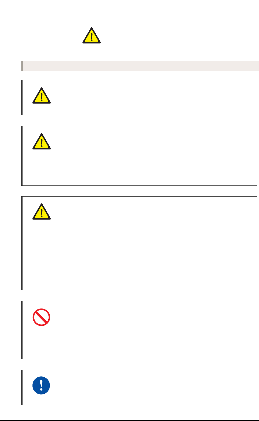
Figure 1.1 RRH-2WB Configuration
[Bottom View]
[Front View] [Right View]
[Top View]
[Left View]
143.5 (5.65)
354 (13.94)
370 (14.57)
504 (19.84)
520 (20.47)
112 (4.41)
Unit: mm (in.)
CHAPTER 1. Before Installation
1-2 © SAMSUNG Electronics Co., Ltd.
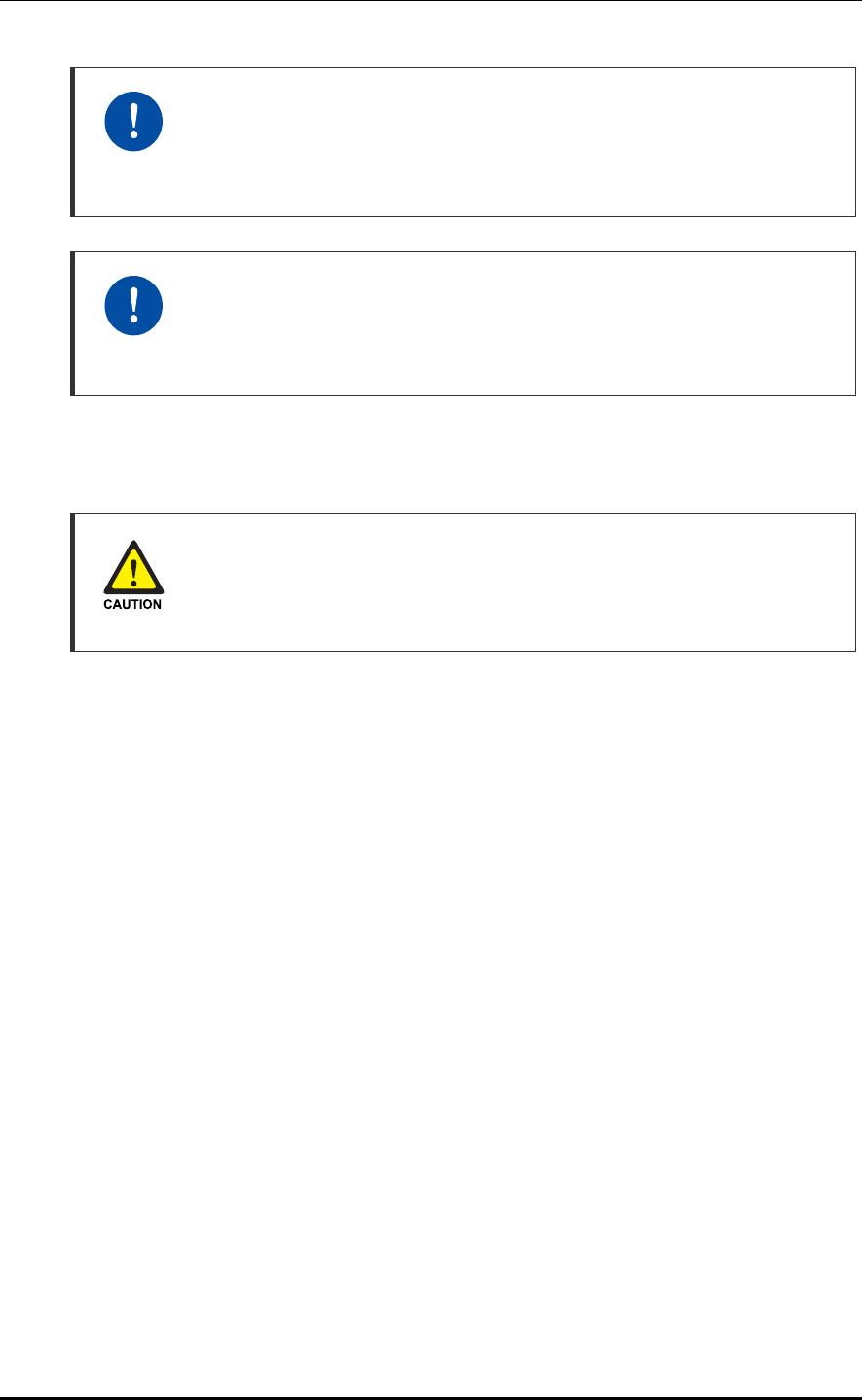
When the solar shield is assembled, the RRH-2WB should be configured as follows:
Figure 1.2 RRH-2WB Configuration When the Solar Shield is Assembled
[Bottom View]
[Front View] [Right View]
[Top View]
[Left View]
169 (6.65)
386.5 (15.22)
576 (22.68)
Unit: mm (in.)
Mobile WiMAX/TD-LTE RRH-2WB Installation Manual/Ver.2.0
© SAMSUNG Electronics Co., Ltd. 1-3
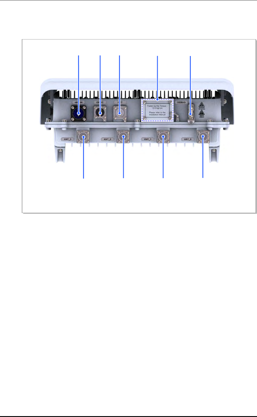
RRH-2WB External Interface
The external interface of RRH-2WB is as follows:
Figure 1.3 RRH-2WB External Interface
[Bottom View]
ATN_3 ATN_0
ATN_1ATN_2
-48 V IN Optic RET Frame Ground
Debug
CHAPTER 1. Before Installation
1-4 © SAMSUNG Electronics Co., Ltd.
1.2 Specifications
RF Specification
The RF specification of the RRH-2WB is as follows:
Category System Capacity
Channel Bandwidth - Mobile WiMAX: 10 MHz
- TD-LTE: 20 MHz
RF Band 2,496~2,690 MHz
Maximum Number of Carriers - 10 MHz Mobile WiMAX 1 carrier/path
- 20 MHz TD-LTE 1 carrier/path
Interface between DU and RRH-2WB CPRI, Optic (4 Core)
In band Spectral Mask FCC 43 + 10 logP
Tx/Rx Performance - Mobile WiMAX: RCT
- TD-LTE: 3 GPP TS 36.104
Output Antenna Port-based
- 5 W/Carrier/Path @ WiMAX 10 MHz
- 10 W/Carrier/Path @ TD-LTE 20 MHz
Input Power
The table below lists the power standard for the RRH-2WB.
Category Standard
System Input Voltage -48 VDC (Voltage Variation Range: -40~-56 VDC)
System Input Current (Max.) 6.25 A @ -48 V
System Input Voltage
If the operator wants AC power for the system input voltage, it can be supplied
using an additional external rectifier.
Unit Size and Weight
The table below lists the size and weight of the RRH-2WB.
Category Standard
Size mm 354 (W) × 112 (D) × 504 (H)
in. 13.94 (W) × 4.41 (D) × 19.84 (H)
Weight kg 20.4 or less
lb 45 or less

Mobile WiMAX/TD-LTE RRH-2WB Installation Manual/Ver.2.0
© SAMSUNG Electronics Co., Ltd. 1-5
Environmental Condition
The table below lists the environmental conditions and related standards such as
operational temperature and humidity.
Category Range
Temperature Conditiona) -40~+50°C (-104~122°F)
Humidity Conditiona) 5~100%, condensing, not to exceed 30g/m3 absolute humidity
Altitude -60~1,800 m (197~6,000 ft)
Vibration GR-487-CORE Sec.3.39
- Transportation shock
- Transportation vibration
- Installation shock
- Environmentally induced vibration
- Earthquake resistance
Noise (sound pressure level) Under 65 dBA in height of 1.0 m (3 ft) and distance of 1.5 m (5 ft).
Electromagnetic Wave (EMI) FCC Title 47 Part 15 Class B
EN 301 489 Section 7.1 EMC emission
GR-1089-CORE(Issue4) Sec. 3.2 Emission Criteria
RF Regulation FCC Title 47 Part 27
a) The standards of temperature/humidity conditions are based on the value on the position where is 400 mm
(1.3 ft) away from the front of the DU and in the height of 1.5 m (5 ft) on the bottom.
RF Specification
The table below lists the RF characteristics of the RRH-2WB.
Category Description
Total Tx Output Power 40 W
- Mobile WiMAX: 5 + 5 W
- TD-LTE: 10 + 10 + 10 + 10 W
Tx Constellation error - Mobile WiMAX: RCT
- TD-LTE: 3 GPP TS 36.104
RX Sensitivity - Mobile WiMAX: RCT
- TD-LTE: 3 GPP TS 36.104
CHAPTER 1. Before Installation
1-6 © SAMSUNG Electronics Co., Ltd.
1.3 Cautions for Installation
Observe the following safety instructions when installing the RRH-2WB:
Before Installing
Post warning signs in areas where high-voltage cables are installed.
Post ‘off limit’ signs in areas where accidents are most expected.
With guardrails or fences, block open areas such as connecting parts, roof, and scaffold.
While Installing
The power must be cut off before installing.
Be careful that boards mounted on the system and the cables among the boards are
damaged or scratched when the system is transported or installed.
Power Switch Off
Make sure the power switch of power supplier is off when installing the system.
Installing the system with power switch on may cause system damage or fatal
human injury when cables are not correctly connected.
Protection gloves and goggles
Make sure that worker wears protection gloves and goggles to prevent damages
from debris while drilling holes in a wall or ceiling.
Watches, Rings, and Other Metallic Accessories
Do not wear accessories such as watches and rings in order to prevent electrical
shock.
Do not Work by Yourself
Worker must not work alone in any key process.
System Installation and Access
Only authorized workers are allowed to install or access the system.
Mobile WiMAX/TD-LTE RRH-2WB Installation Manual/Ver.2.0
© SAMSUNG Electronics Co., Ltd. 1-7
Fixing Materials for outdoor
Stud bolts, Hex. nuts, spring washers, and plane washers that are used to fix the
pole should be made of stainless materials (STS 304). If not, the joint parts may
oxidize or gather rust.
After Installing
Cover the cable holes drilled on the floor with a solid cover.
Remove any debris produced during the work and clean up the installation site.
Warning for Laser Beam Running through Optical Cables
In the system, the laser beam emitting light runs through the optical cable.
The exposure of the laser beam on worker’s eye may cause serious injury so that
it should be handled with care.
Cautions while Cleaning the Rack
Make sure that worker does not damage installed cables while cleaning the rack.
Cautions while Cleaning Power Supply
While cleaning the power supply device, take caution that the device does not
come in contact with alien bodies that may cause power failure.
Management of Unused Ports
Cover the unused ports (conduit, cable gland, etc.) with waterproof cap (sealing
cap) to prevent infiltration of foreign material such as dust, moisture, or bug.

CHAPTER 1. Before Installation
1-8 © SAMSUNG Electronics Co., Ltd.
1.4 Pre-survey
Before starting the construction, the constructor and the departments concerned with the
construction inspect the following items with a pre-survey checklist for the smooth
progress of the construction. If any insufficiencies or problems are found, make the plan
upon deliberation with the departments.
Installation/construction personnel and the service provider carry out the site survey for the
system installation focusing on the following items:
Examination about the conformance and the economical efficiency of the place that
the system is transported or installed.
Status of external interfaces
Power capacity and wiring status
Possibility of system extension
Review if the place has the enough space to operate and maintain.
Mobile WiMAX/TD-LTE RRH-2WB Installation Manual/Ver.2.0
© SAMSUNG Electronics Co., Ltd. 1-9
1.5 Installation Tools
The basic tools for installation are listed in the table below. The additional tools required
for each site need to identified and prepared during a site survey before starting installation.
Table 1.1 Basic Installation Tools
No. Name Specification
1 Torque driver set - No.0~+ No.3 (M2.6~M6 ‘+’ Driver)
- 1.0~60 kgf.cm (0.07~4.34 lbf·ft)
2 Torque wrench set - M6~M12
- 10~30 kgf.cm (0.72~2.17 lbf·ft), 100~500 kgf.cm
(7.23~36.15 lbf·ft), Replaceable head
3 Nut driver set 6~10 mm (0.24~0.39 in.)
4 Hacksaw Frame/Blade Normal/HIS
5 Level/Plumb bobs Normal/500 g (1.10 lb)
6 Heating gun 50~300°C (122~572°F)
7 Solder 30~130 W
8 Power extension cable 30 m
9 Tape measure 5 m/50 m (196.85 in./1.97 in.)
10 Cable cutter 325 mm (12.80 in.)
11 Silicon gun/Silicon Normal/Gray & Colorless
12 Spanner 19 mm, 24 mm, 36 mm (0.75 in. 0.94 in. 1.42 in.)
Precautions when Using the Installation Tools
The required installation tools may vary depending on the conditions at the site.
In addition to the basic tools, a protractor, compass, GPS receiver, ladder, safety
equipment, cleaning tools etc. should also be prepared in consideration of the site
conditions.

CHAPTER 1. Before Installation
1-10 © SAMSUNG Electronics Co., Ltd.
This page is intentionally left blank.
Mobile WiMAX/TD-LTE RRH-2WB Installation Manual
© SAMSUNG Electronics Co., Ltd. 2-1
CHAPTER 2. Installing System
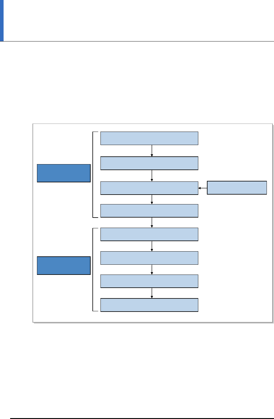
2.1 Installing the RRH-2WB
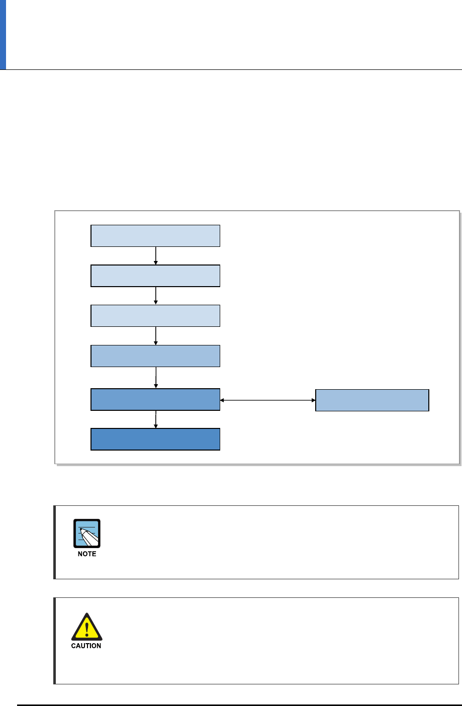
The procedure to install the RRH-2WB is listed in the flow chart below.
Figure 2.1 Procedure to Install the RRH-2WB
Unpacking and Transporting
Fixing System
Grounding
Power Construction
External Interface Construction
CHAPTER 2.
Installing System
CHAPTER 3.
Connecting Cables
Foundation Work
Installation Test
Insulation Test
System Leveling
CHAPTER 2. Installing System
2-2 © SAMSUNG Electronics Co., Ltd.
2.2 Foundation Work
2.2.1 System Arrangement
A certain distance must be secured around the RRH-2WB in each direction for installation
and maintenance.
Table 2.1 Recommended Distances for System
Category Recommended Distances
Front/Rear 800 mm (31.50 in.) or more
Side 200 mm (7.87 in.) or more
Top/Bottom (In case of Pole Type) 1,000 mm (39.37 in.) or more
Figure 2.2 RRH-2WB Installation Space
System Installation Spaces
The space specifications in the Figure above apply when the pole diameter is
101.6 mm (4 in.). The dimensions may vary depending on the diameter of the
pole.
Pole[76.3~114.3 (3~4.5)]
[Pole Type-3 RRH]
630.5 (24.82)
720.5 (28.37)
Pole[76.3~114.3 (3~4.5)]
[Pole Type-1 RRH]
390 (15.35)
140 (5.51)
200 (7.87)
390 (15.35)
[
Tower T
yp
e
]
200 (7.87)
Towe
r
Unit: mm (in.)
Mobile WiMAX/TD-LTE RRH-2WB Installation Manual/Ver.2.0
© SAMSUNG Electronics Co., Ltd. 2-3
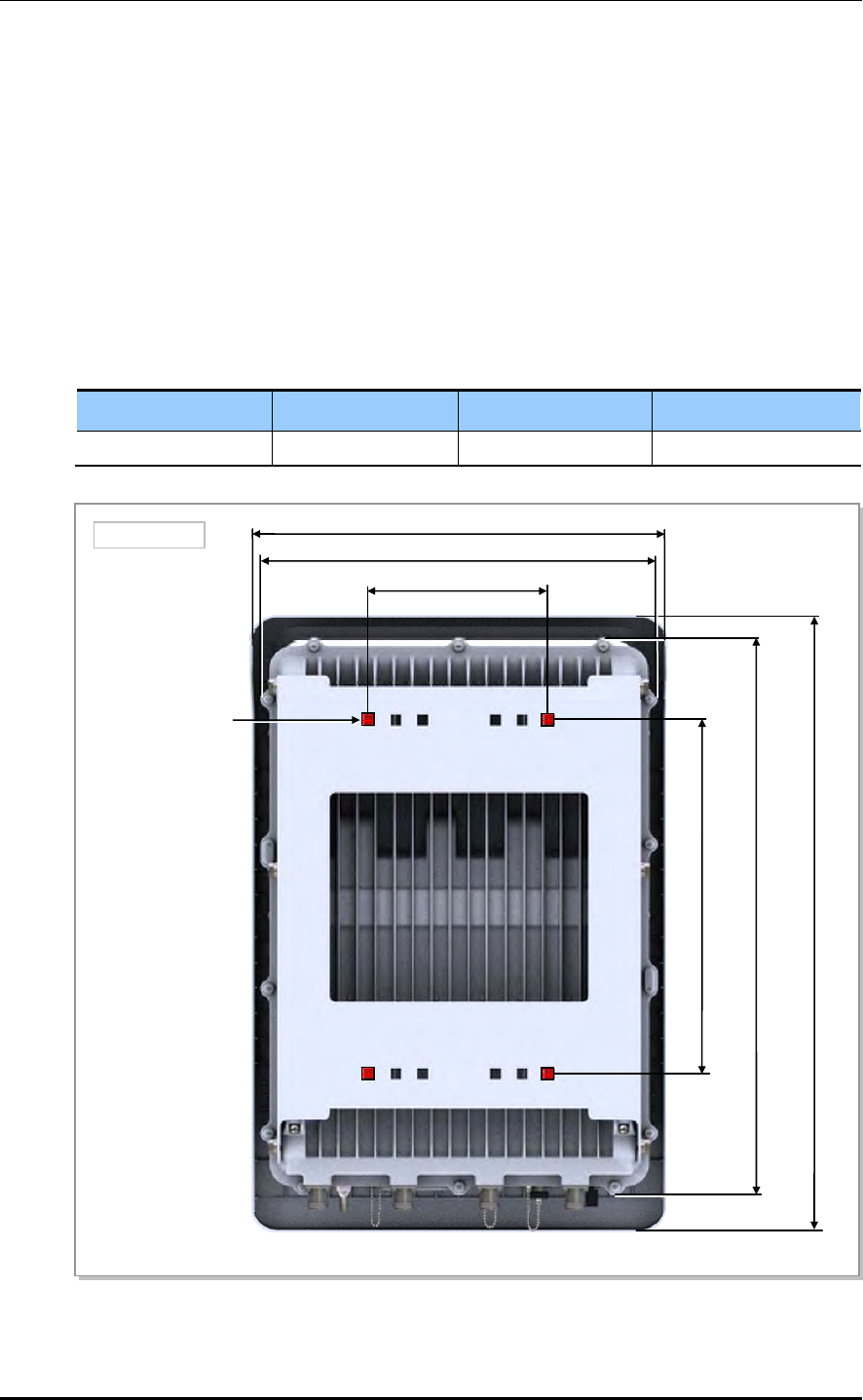
2.2.2 Marking and Drilling
System marking helps install the system in a precise location by marking the locations of
the system, anchor bolts, and cable racks on the floors, walls, and ceilings. When marking
is completed, drill holes for anchor bolts.
1) On the location of the system installation, mark the positions of the equipment and
anchor bolts as shown in the Figure below.
2) Drill holes to insert the anchor bolts and cover the holes with acetate tape before
installing the system.
Table 2.2 Anchor Bolt Drill Bits and Hole Depth
Mounting Method Anchor Bolt Drill Bits Hole Depth
Wall mount M6 10 mm (0.39 in.) 33 mm (1.3 in.)
Figure 2.3 RRH-2WB Marking
Anchor Bolt Hole
[Rear View]
168 (6.61)
370 (14.57)
576 (22.68)
520 (20.47)
330 (12.99)
390 (15.35)
Unit: mm (in.)

CHAPTER 2. Installing System
2-4 © SAMSUNG Electronics Co., Ltd.
2.3 Unpacking and Transporting
This paragraph describes the work to unpack cabinets and other components and transport
them to the place to be installed. The cabinet is externally packed and cabinet and other
components are individually packed.
The external packing should be unpacked in the outside. If necessary, the packing can
be unpacked after transported into the area near installation place.
Transport the cabinet to the installation place. Beware of the damage of walls, pillars,
and bottom of the passage when transporting the cabinet.
Transport other components with packing and sort by types.
2.3.1 Importing Items
Bring in items, taking care of the followings:
Regarding equipment weight and size, check the path to bring the equipment.
Lay Iron and veneer boards on stairs or doorsills to make the transportation easy.
When bring in equipment, beware of damage or impairment of main entrance, walls,
pillars, and floors of the station. Prepare protection materials and fix them with a high-
strength adhesive.
Carry boards in packing status, and unpack them when installing or mounting.
Vibration Level for Transportation
When carrying the system, fasten the system firmly not to exceed the proper vibration level
from 1 to 500 Hz.
When carrying system, use a lift to prevent accidents. However, if the system should be
carried by people, enough people are required to carry the system.
Before moving the system, check the storage place for the system and remove obstacles in
advance. While moving system, boards and other devices should not be shocked physically
and damaged caused by dust, moisture, and static electricity.
When installing the items imported, system must be installed in a location whose access is
not easy from outside.
2.3.2 Unpacking Items
The procedure to unpack items is as follows:
1) The packing items should be packed until they reach the installation place.
2) The items are classified in accordance with each job specification and stored on a
place that does not interfere with working.
3) Unpacked systems should be installed immediately. If not installed immediately, the
systems should be stored in the installation place temporarily.
4) Unpack only external packing, leaving the internal packing in unpacked status.
5) Unpack the inner packaging after each system is placed on its installation location.
6) Do not recycle packaging waste. Dispose of it in consultation with the provider.
Mobile WiMAX/TD-LTE RRH-2WB Installation Manual/Ver.2.0
© SAMSUNG Electronics Co., Ltd. 2-5
2.4 Fixing the System
2.4.1 Fixing the Wall Type RRH-2WB
The procedure for fixing the wall type RRH-2WB is as follows:
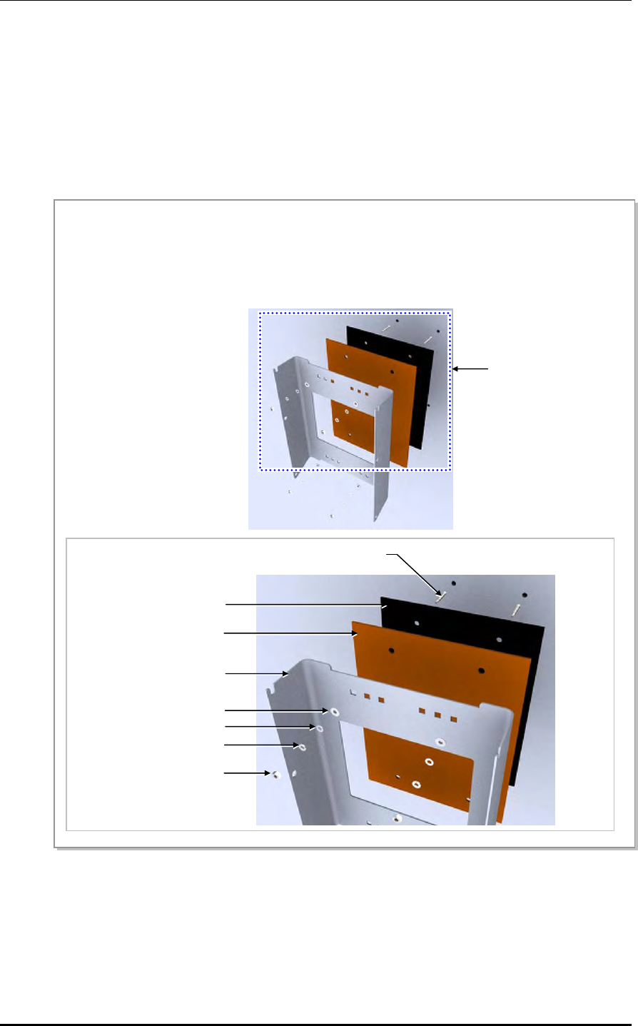
1) Fixing the RRH-2WB Unit Mounting Bracket
Figure 2.4 Fixing the RRH-2WB_Wall Type (1)
Detail ‘A’
‘A’
M6 Insulation Bushing
M6 Anchor Bolt Ass’y
Rubber Pad
Bakelite
RRH-2WB
Unit Mounting Bracket
M6 Spring Washe
r
M6 Hex. Nut
M6 Plane Washe
r
1) To mount the RRH-2WB on the wall, first fix an M6 anchor bolt assembly at the marked location on the wall.
2) Fit the rubber pads, the bakelites, and the RRH-2WB unit mounting bracket to the fixed M6 anchor bolt
assembly, and firmly fix them using the M6 insulation bushings, plane washers, spring washers, and Hex.
nuts in the order.
CHAPTER 2. Installing System
2-6 © SAMSUNG Electronics Co., Ltd.
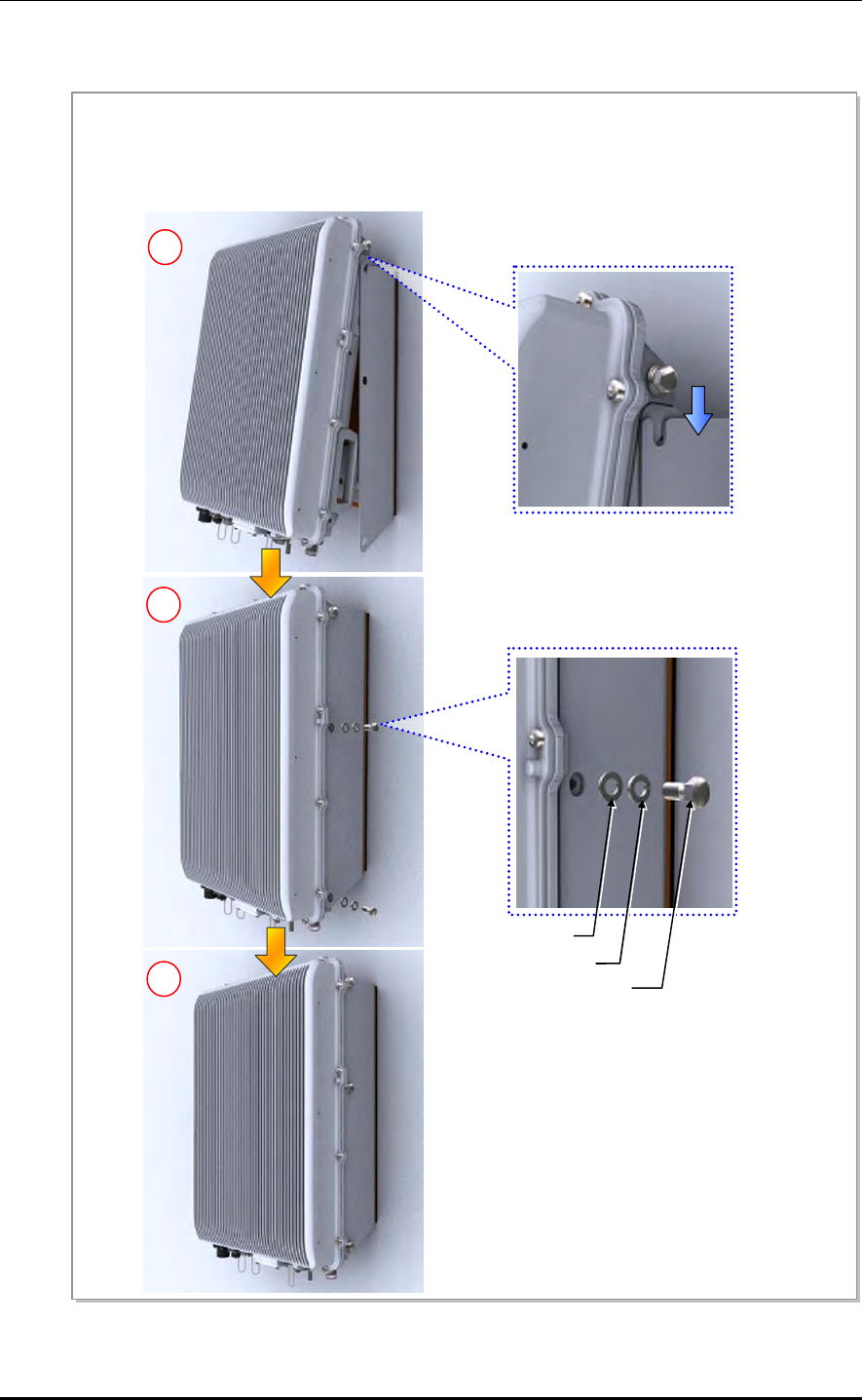
2) Fixing the RRH-2WB to the RRH-2WB Unit Mounting Bracket
Figure 2.5 Fixing the RRH-2WB_Wall Type (2)
1
2
M8 × 15L Hex. Bolt
M8 Spring Washer
M8 Plane Washer
3
Temporarily fix the M8 hex. bolt, plane washer, and spring washer loosely to the left/right fixing hole on the
top of the RRH-2WB. Hang the RRH-2WB to the hooking holes at the top of the RRH-2WB unit mounting
bracket. Then align the RRH-2WB with the fixing holes of the RRH-2WB unit mounting bracket and fix them
firmly.
Mobile WiMAX/TD-LTE RRH-2WB Installation Manual/Ver.2.0
© SAMSUNG Electronics Co., Ltd. 2-7
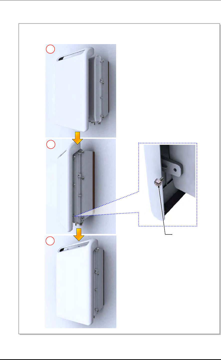
3) Assembling the Solar Shield to RRH-2WB
Figure 2.6 Fixing the RRH-2WB_Wall Type (3)
1
2
M5 × 12L SEMS
3
A
lign the solar shield cover with the fixing holes of the RRH-2WB and then fix them firmly using M5 SEMS
screws.
CHAPTER 2. Installing System
2-8 © SAMSUNG Electronics Co., Ltd.
2.4.2 Fixing the Pole Type RRH-2WB
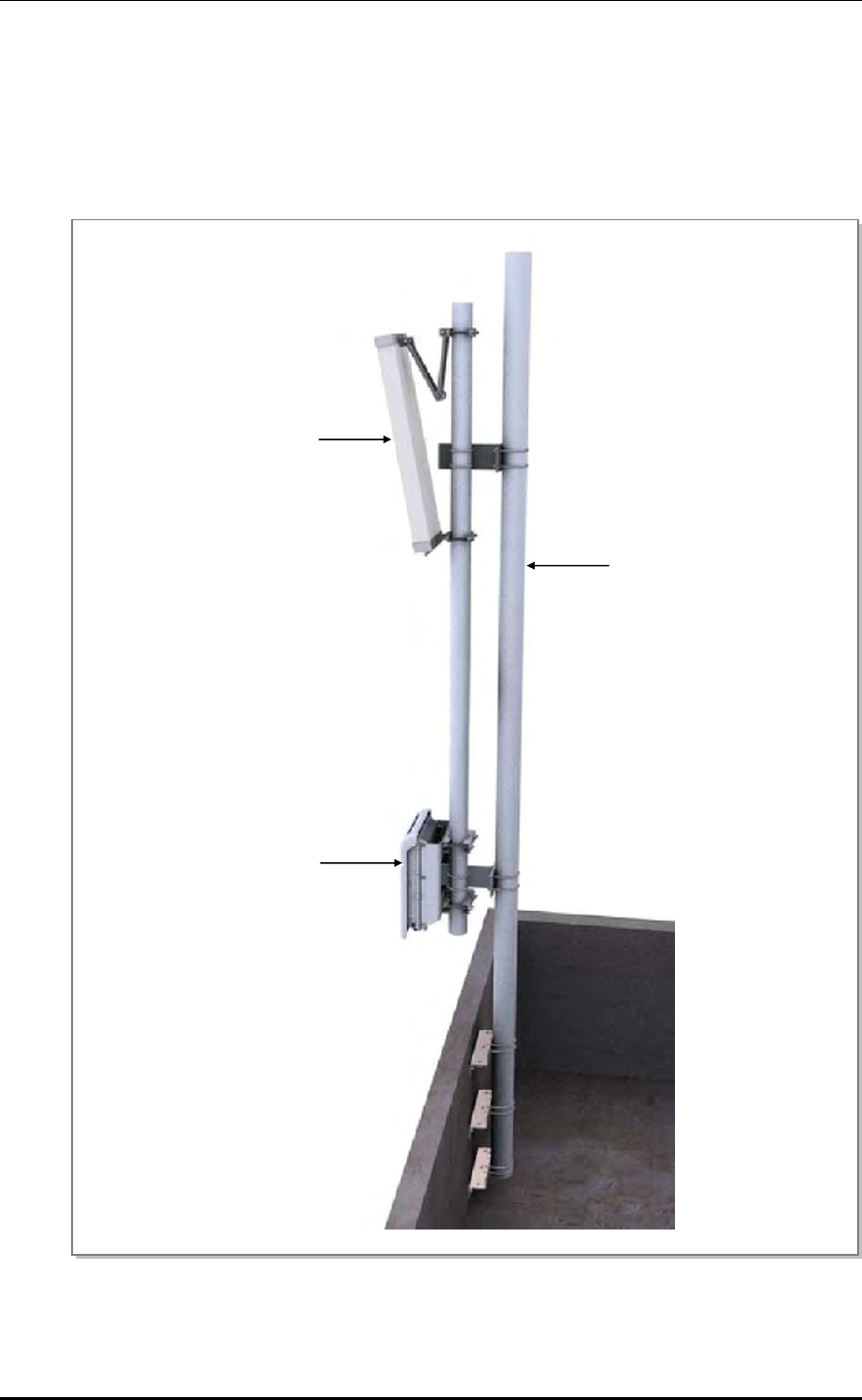
Installing on Wall Mount Pole
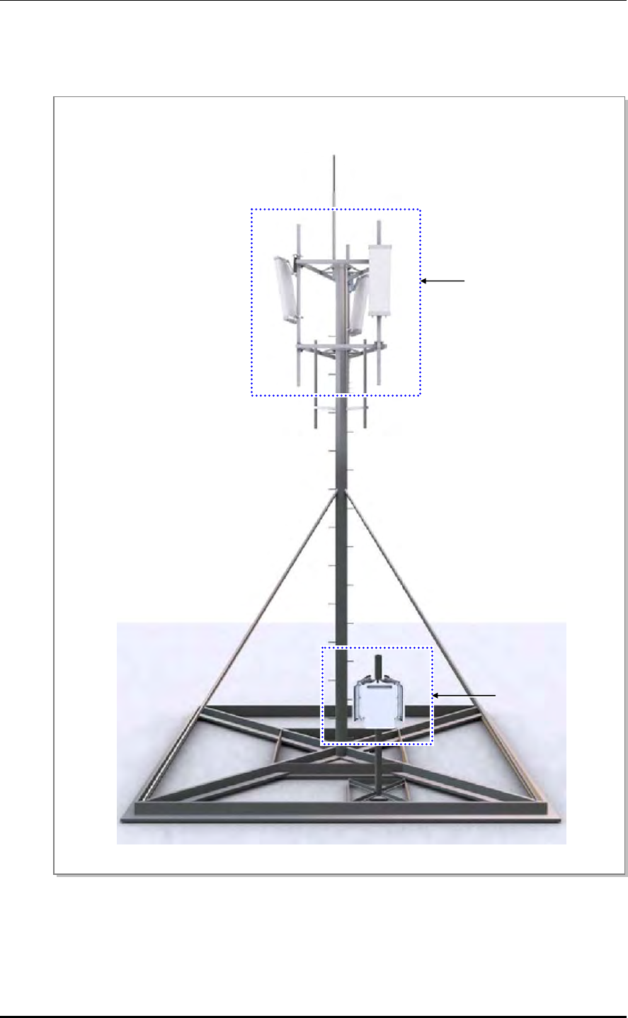
The following is an example of installing RRH-2WB and a sector antenna to the wall
mount pole:
Figure 2.7 Example of Installing on Wall Mount Pole
Sector Antenna (4T4R)
RRH-2WB
Wall Mount Pole
Mobile WiMAX/TD-LTE RRH-2WB Installation Manual/Ver.2.0
© SAMSUNG Electronics Co., Ltd. 2-9
Installing on Mono Pole
The following is an example of installing RRH-2WB and a sector antenna to the mono
pole:
Figure 2.8 Example of Installing on Mono Pole
RRH-2WB
Sector Antenna (4T4R)
CHAPTER 2. Installing System
2-10 © SAMSUNG Electronics Co., Ltd.
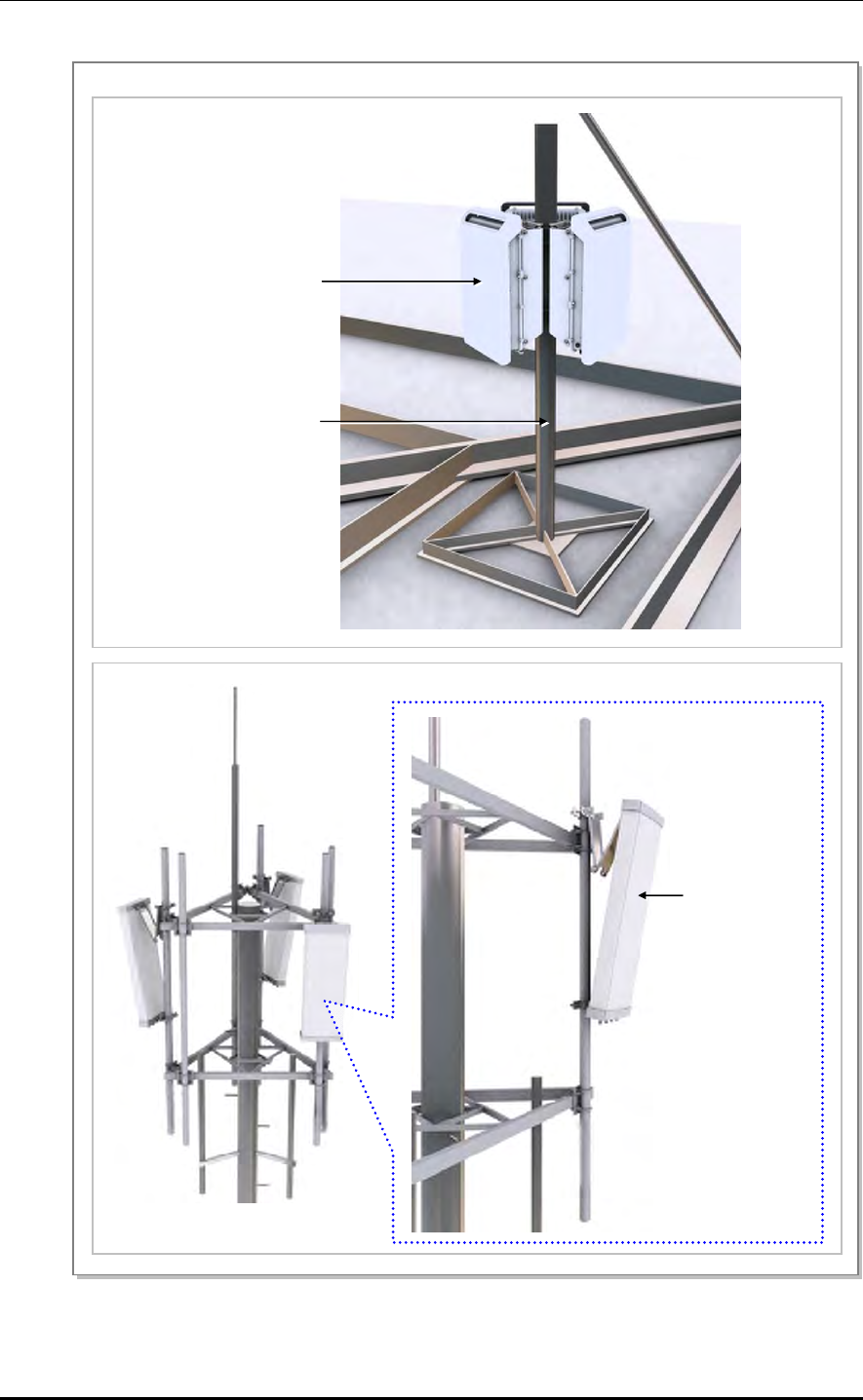
Installing on Pole
The following is an example of installing RRH-2WB and a sector antenna to the pole:
Figure 2.9 Example of Installing on Pole
‘B’
‘A’
Mobile WiMAX/TD-LTE RRH-2WB Installation Manual/Ver.2.0
© SAMSUNG Electronics Co., Ltd. 2-11
Figure 2.10 Example of Installing on Pole (Detail A, Detail B)
Detail ‘A’
RRH-2WB
Pole for RRH-2WB Fixing
Detail ‘B’
Sector Antenna
(4T4R)
CHAPTER 2. Installing System
2-12 © SAMSUNG Electronics Co., Ltd.
2.4.2.1 Fixing 1 Sector Pole Type RRH-2WB
Fix 1 sector pole type RRH-2WB in the following steps.
1) Fixing the RRH-2WB Unit Mounting Bracket and Pole Mount Bracket
Figure 2.11 Fixing 1 Sector Pole Type RRH-2WB (1)
Pole Mounting Bracket RRH-2WB Unit Mounting
Bracket
M8 Hex.Nut
M8 × 180L Carriage Bolt
M8 Plane Washer
M8 Spring Washer
To install the RRH-2WB into a pole, fix the RRH-2WB unit mounting bracket and the pole mounting bracket
firmly using M8 carriage bolts, plane washers, spring washers, and hex. nuts.
Mobile WiMAX/TD-LTE RRH-2WB Installation Manual/Ver.2.0
© SAMSUNG Electronics Co., Ltd. 2-13
2) Fixing the RRH-2WB to the RRH-2WB Unit Mounting Bracket
Figure 2.12 Fixing 1 Sector Pole Type RRH-2WB (2)
1
2
M8 × 15L Hex. Bolt
M8 Spring Washer
M8 Plane Washer
3
Temporarily fix the M8 hex. bolt, plane washer, and spring washer loosely to the left/right fixing hole on the
top of the RRH-2WB. Hang the RRH-2WB to the hooking holes at the top of the RRH-2WB unit mounting
bracket. Then align the RRH-2WB with the fixing holes of the RRH-2WB unit mounting bracket and fix them
firmly.
CHAPTER 2. Installing System
2-14 © SAMSUNG Electronics Co., Ltd.
3) Assembling the Solar Shield to RRH-2WB
Figure 2.13 Fixing 1 Sector Pole Type RRH-2WB (3)
1
2
M5 × 12L SEMS
3
A
lign the solar shield cover with the fixing holes of the RRH-2WB and then fix them firmly using M5 SEMS
screws.
Mobile WiMAX/TD-LTE RRH-2WB Installation Manual/Ver.2.0
© SAMSUNG Electronics Co., Ltd. 2-15
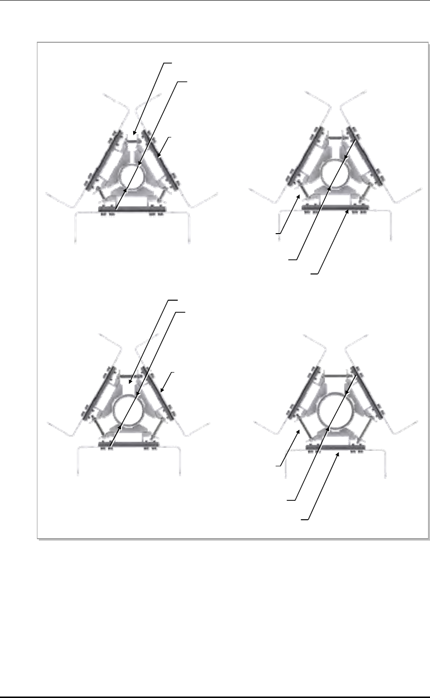
2.4.2.2 Fixing 3 Sector Pole Type RRH-2WB
Fix 3 sector pole type RRH-2WB in the following steps.
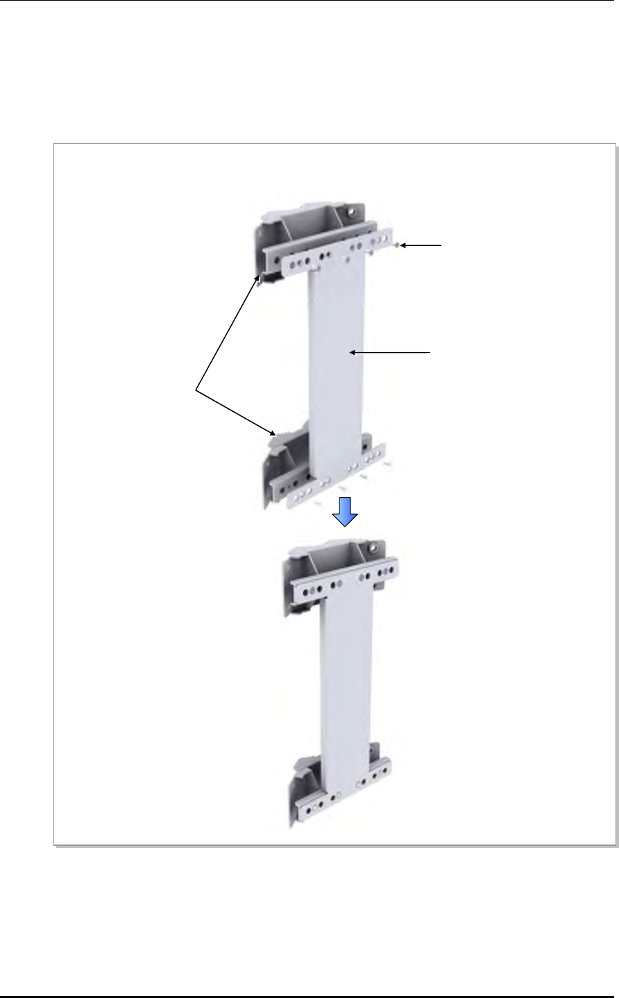
1) Assembling 3 sector Pole Mount Bracket
Figure 2.14 Fixing 3 Sector Pole Type RRH-2WB (1)
Attach a pole mount bracket-jig to the 3 sector pole mount brackets. Fix the brackets to each other using M4
flat head screws at 8 fixing spots.
Pole Mount Bracket-jig
Pole Mount Bracket
M4 × 8L Flat Head Screw
CHAPTER 2. Installing System
2-16 © SAMSUNG Electronics Co., Ltd.
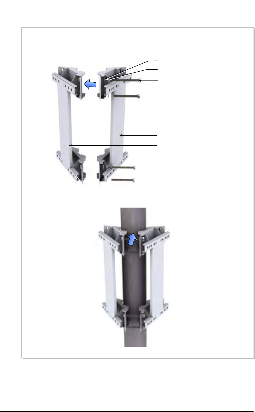
2) Fixing 3 sector Pole Mount Bracket Assemblies 1 and 2
Figure 2.15 Fixing 3 Sector Pole Type RRH-2WB (2)
M8 × 80L Hex. Bolt
M8 Spring Washer
M8 Plane Washer
3 Sector Pole Mounting Bracket Ass’y-1
3 Sector Pole Mounting Bracket Ass’y-2
Assemble 3 sector pole mount bracket assemblies 1 and 2. Firmly fix the two assemblies to each other
using M8 × 80L Hex. bolts, spring washers, and plane washers at 4 fixing spots.
Mobile WiMAX/TD-LTE RRH-2WB Installation Manual/Ver.2.0
© SAMSUNG Electronics Co., Ltd. 2-17
3) Fixing the 3 sector Pole Mount Bracket Assembly to the Pole
Figure 2.16 Fixing 3 Sector Pole Type RRH-2WB (3)
‘A’
Detail ‘A’
3 Sector Pole Mounting
Bracket Ass’y-2
3 Sector Pole Mounting
Bracket Ass’y-1
3 Sector Pole Mounting Bracket Ass’y-3
M8 Plane Washe
r
M8 Spring Washe
r
M8 × 80L Hex. Bolt
Fix 3 Sector pole mount bracket assembly 3 to the 3 sector pole mount bracket assemblies 1 and 2. Firmly
fix the assemblies to each other using M8 × 80L Hex. bolts, spring washers, and plane washers.
CHAPTER 2. Installing System
2-18 © SAMSUNG Electronics Co., Ltd.
4) Fixing the RRH-2WB Unit Mounting Bracket to the 3 sector Pole Mount Bracket
Assembly
Figure 2.17 Fixing 3 Sector Pole Type RRH-2WB (4)
RRH-2WB Unit Mounting Bracket
M8 × 25L Hex. Bolt
M8 Spring Washer
M8 Plane Washer
3 Sector Pole Mounting
Bracket Ass’y
Fix the RRH-2WB unit mounting brackets to the 3 sector pole mount bracket assembly attached to the
pole. At this time, the RRH-2WB unit mounting brackets should be firmly fixed using M8 Hex. bolts,
spring washers, and plane washers. Use four sets at the bottom and the top as shown in the Figure.
Mobile WiMAX/TD-LTE RRH-2WB Installation Manual/Ver.2.0
© SAMSUNG Electronics Co., Ltd. 2-19
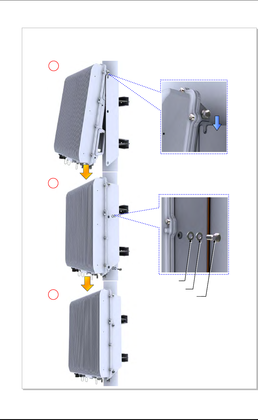
5) Fixing the RRH-2WB to the RRH-2WB Unit Mounting Bracket
Figure 2.18 Fixing 3 Sector Pole Type RRH-2WB (5)
Temporarily fix the M8 hex. bolt, plane washer, and spring washer loosely to the left/right fixing hole on
the top of the RRH-2WB. Hang the RRH-2WB to the hooking holes at the top of the RRH-2WB unit
mounting bracket. Then align the RRH-2WB with the fixing holes of the RRH-2WB unit mounting bracket
and fix them firmly.
1
3
2
M8 × 15L Hex. Bolt
M8 Spring Washer
M8 Plane Washer
CHAPTER 2. Installing System
2-20 © SAMSUNG Electronics Co., Ltd.
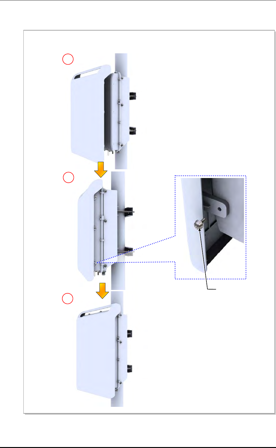
6) Assembling the Solar Shield Cover to RRH-2WB
Figure 2.19 Fixing 3 Sector Pole Type RRH-2WB (6)
1
2
M5 × 12L SEMS
3
A
lign the solar shield cover with the fixing holes of the RRH-2WB and then fix them firmly using M5 SEMS
screws.
Mobile WiMAX/TD-LTE RRH-2WB Installation Manual/Ver.2.0
© SAMSUNG Electronics Co., Ltd. 2-21
Bolt Specifications for 3 Sector Pole Type RRH-2WB-Examples
Figure 2.20 Bolt Specifications for 3 Sector Pole Type RRH-2WB-Examples
M8 × 50L Hex. Bolt
65 A Pole: Ф 76.3 mm (3 in.)
80 A Pole: Ф 89.1 mm (3.5 in.)
90 A Pole: Ф 101.6 mm (4 in.)
100 A Pole: Ф 114.3 mm (4.5 in.)
3 Sector Pole Mounting Ass’y
M8 × 70L Hex. Bolt
3 Sector Pole Mounting Ass’y
M8 × 80L Hex. Bolt
M8 × 80L Hex. Bolt
3 Sector Pole Mounting Ass’y
3 Sector Pole Mounting Ass’
y
CHAPTER 2. Installing System
2-22 © SAMSUNG Electronics Co., Ltd.
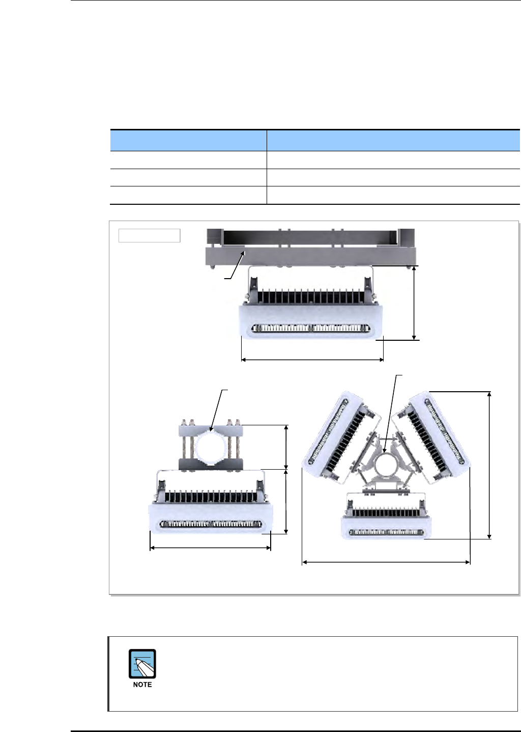
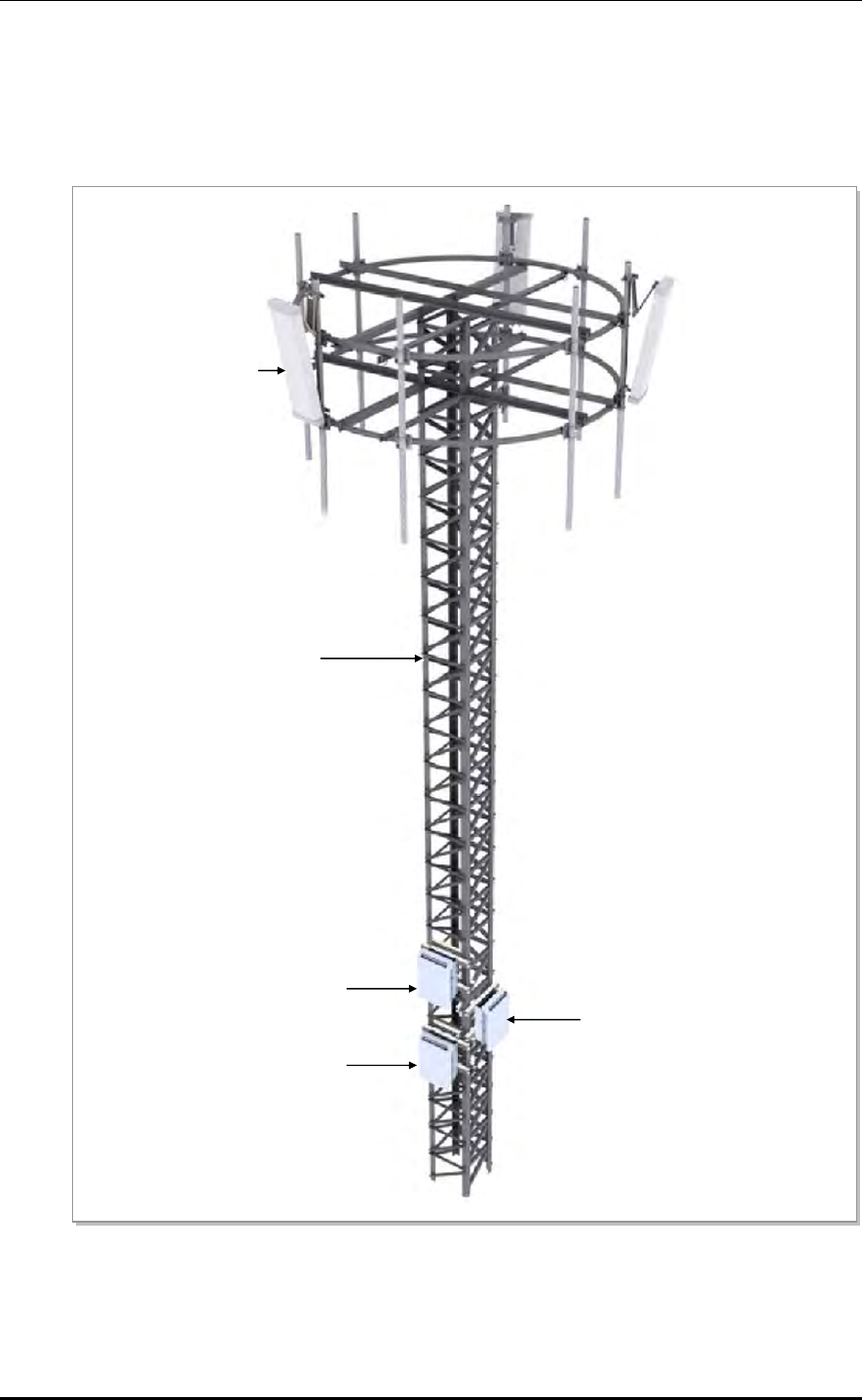
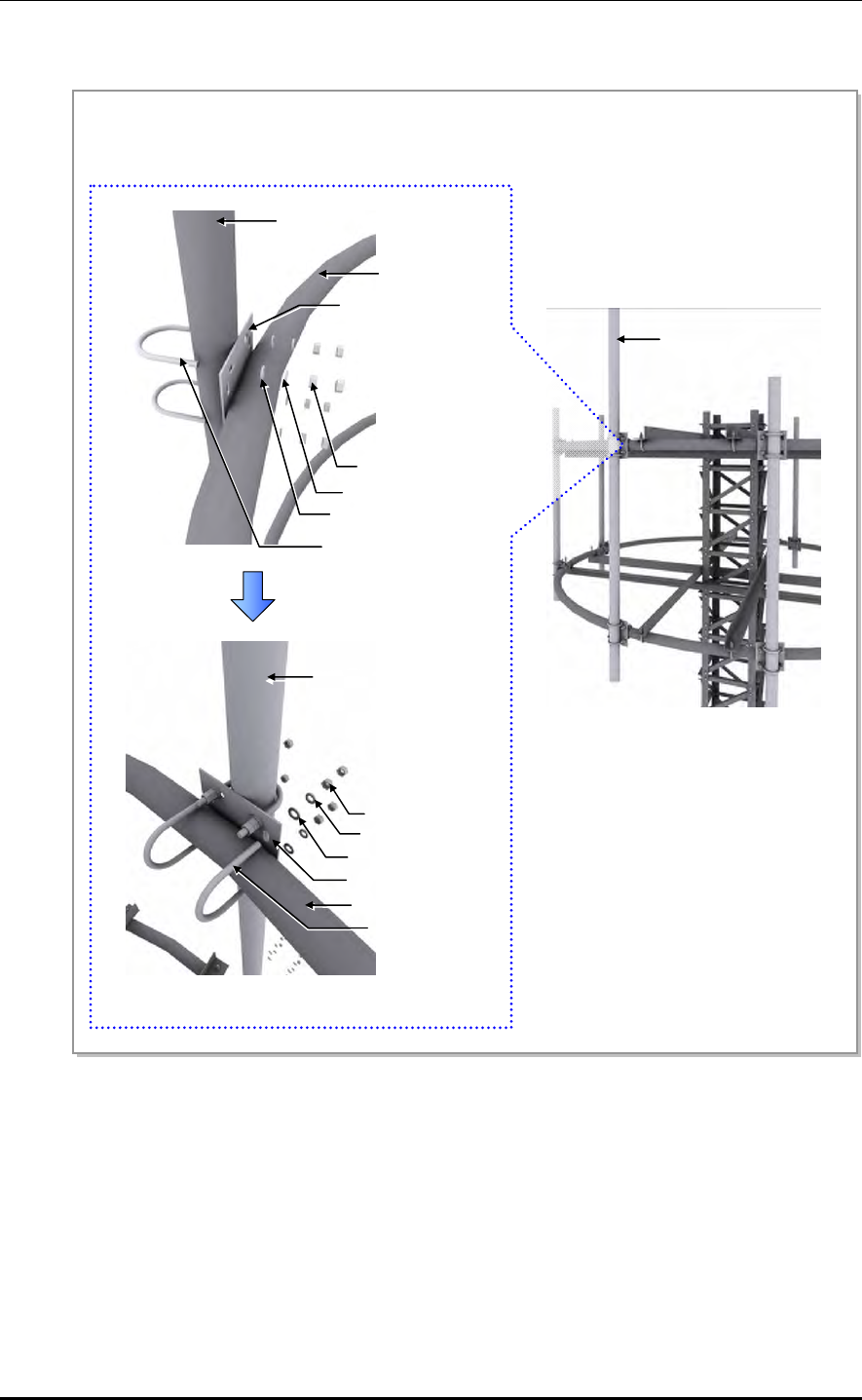
2.4.3 Fixing the Tower type RRH-2WB
Installing on the Tower
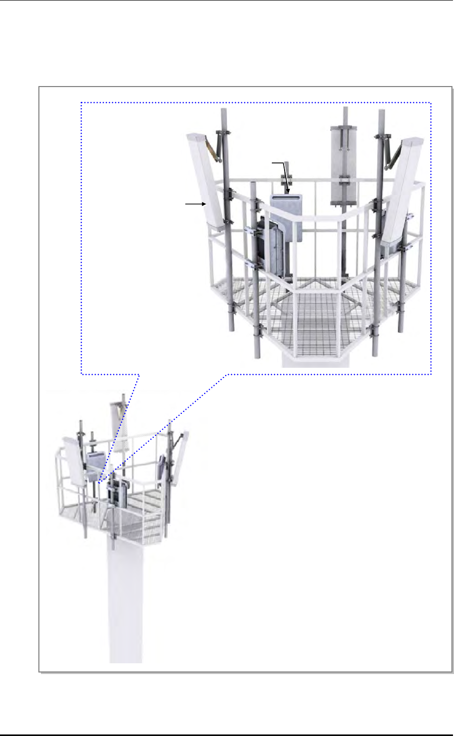
The following is an example of installing RRH-2WB, and a sector antenna to the tower:
Figure 2.21 Example of Installing on the Tower
Sector Antenna (4T4R)
Towe
r
RRH-2WB #2
RRH-2WB #1
RRH-2WB #3
Mobile WiMAX/TD-LTE RRH-2WB Installation Manual/Ver.2.0
© SAMSUNG Electronics Co., Ltd. 2-23
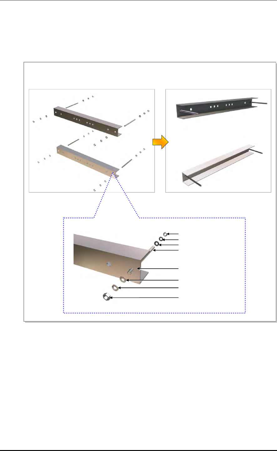
Fixing the Tower type RRH-2WB
Fix tower type RRH-2WB in the following steps.
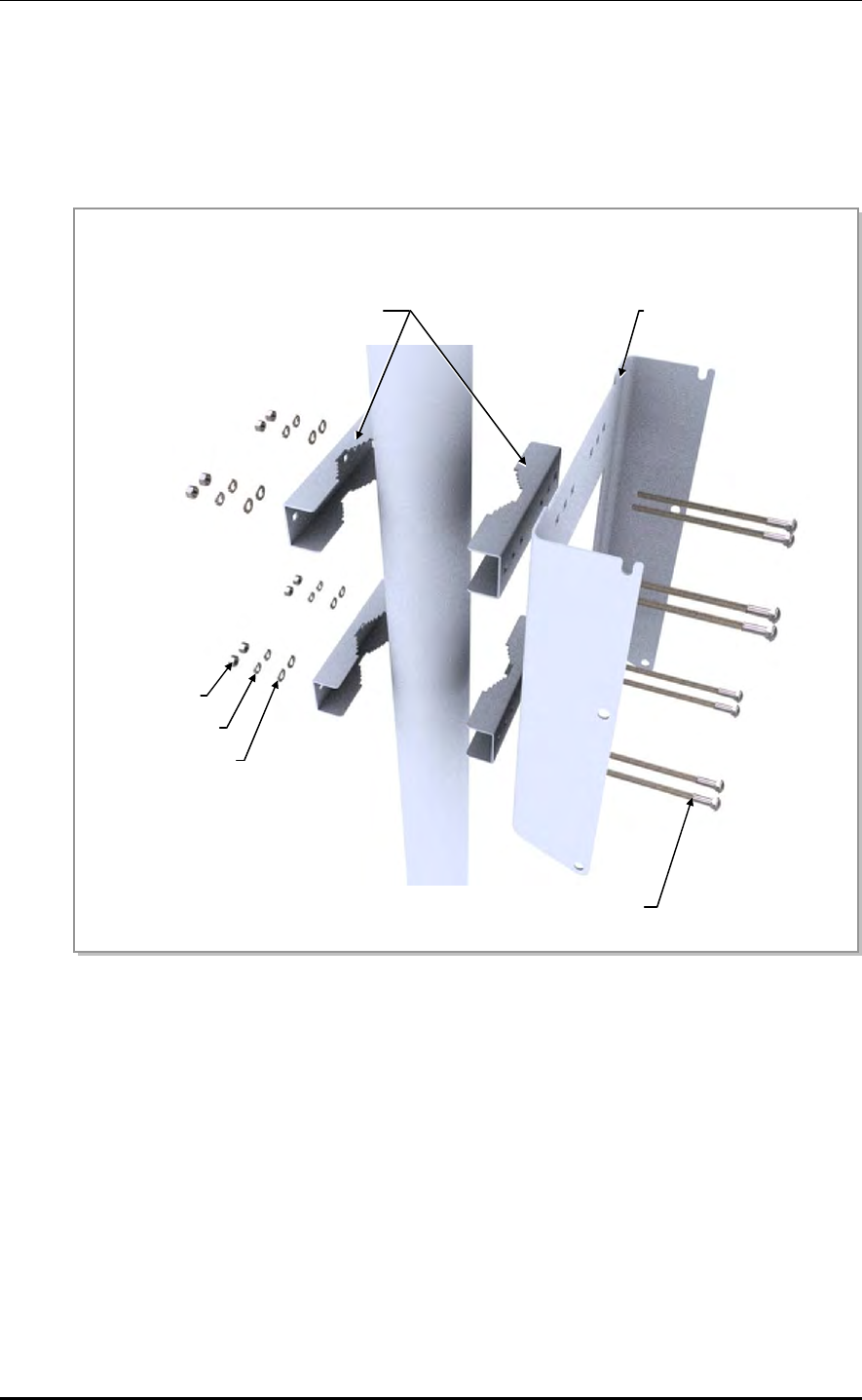
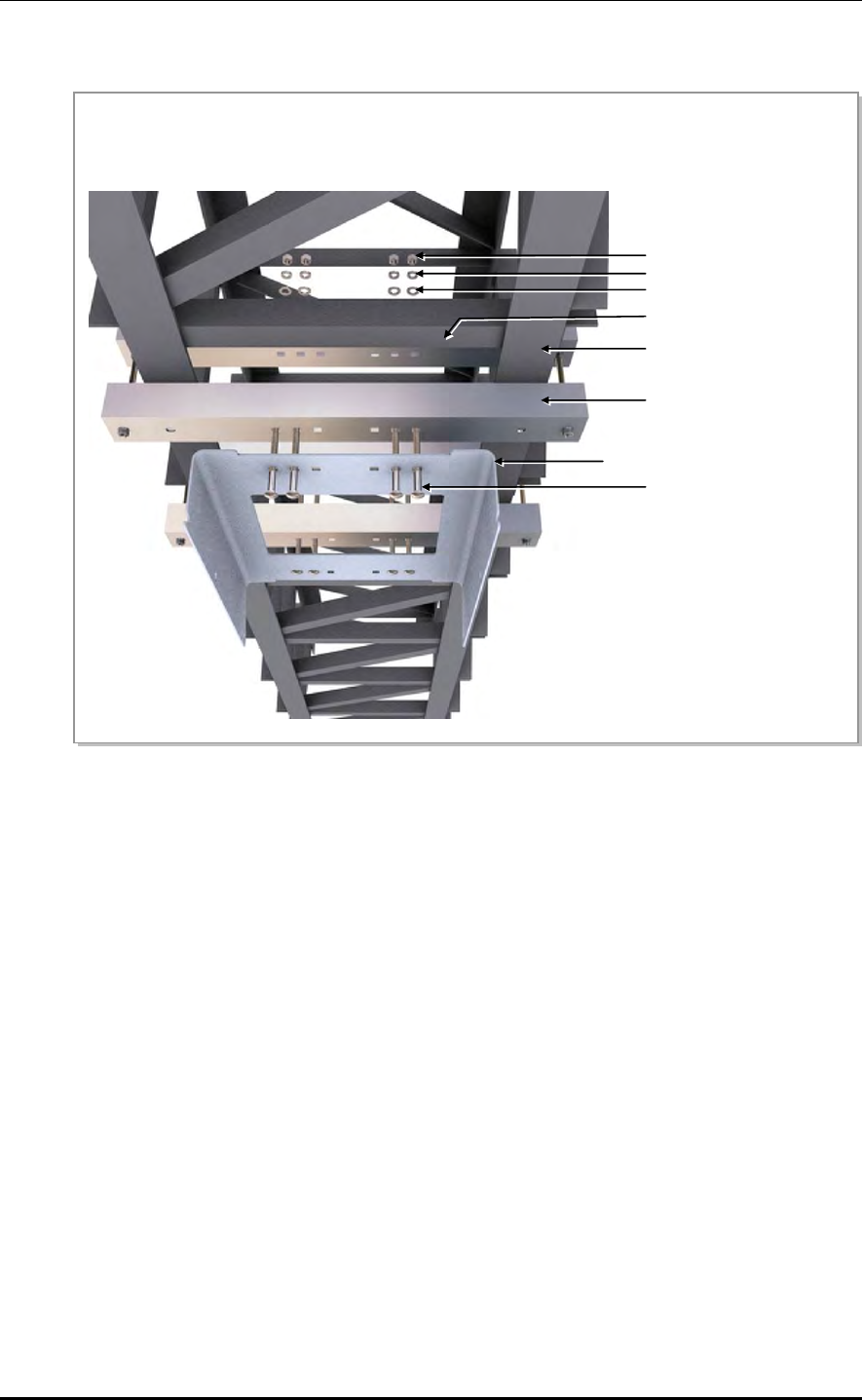
1) Fixing the RRH-2WB Fixing Support to Tower
Figure 2.22 Fixing Tower Type RRH-2WB (1)
a) Tighten the M8 stud bolts to the RRH-2WB fixing support (front side) fixing holes with plane washers,
spring washers, and hex. nuts.
M8 Hex. Nut
M8 Spring Washer
M8 Plane Washer
M8 Stud Bolt
RRH-2WB Fixing Support
(Front Side)
M8 Plane Washer
M8 Spring Washer
M8 Hex. Nut
CHAPTER 2. Installing System
2-24 © SAMSUNG Electronics Co., Ltd.
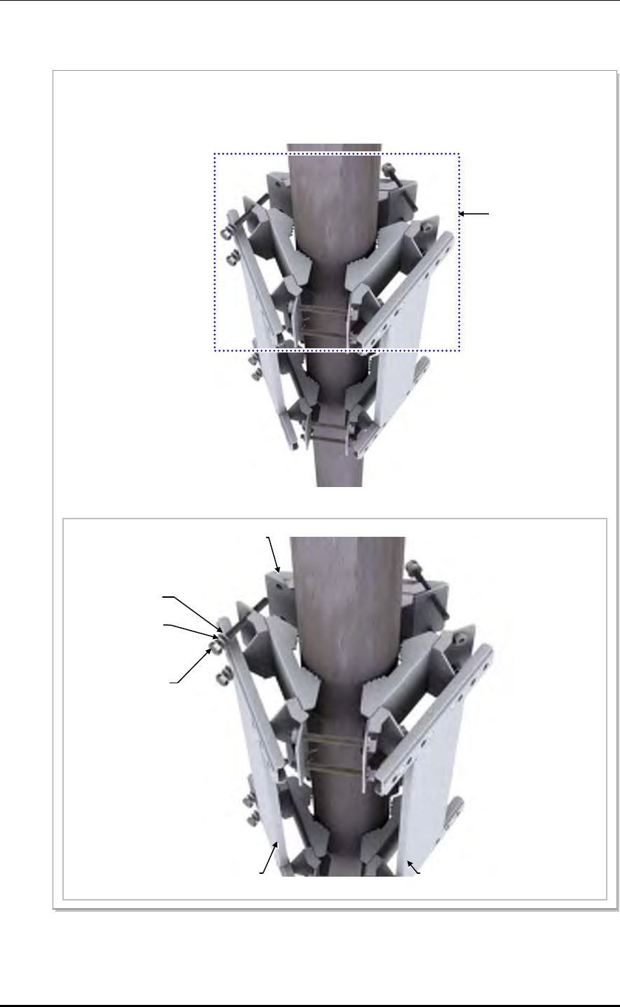
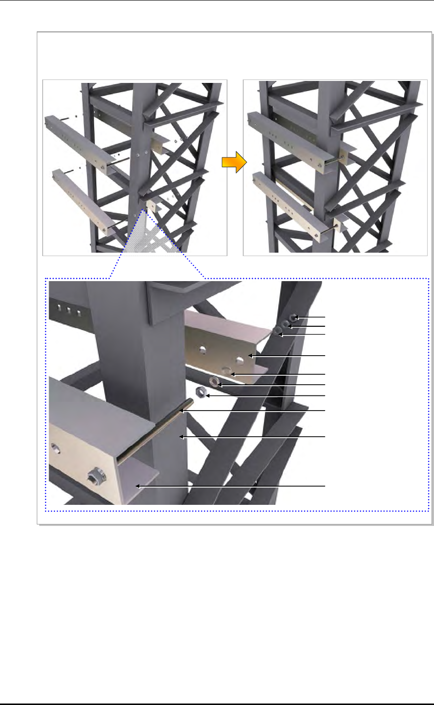
Figure 2.23 Fixing Tower Type RRH-2WB (2)
b) Align the RRH-2WB fixing support (front side) outside of the tower and the RRH-2WB fixing support
(rear side) inside of the tower with each M8 stud bolt and fixing hole, and tighten them with M8 plane
washers, spring washers, and hex. nuts.
M8 Hex. Nut
M8 Spring Washer
M8 Plane Washer
RRH-2WB Fixing Support
(Rear Side)
M8 Plane Washer
M8 Spring Washer
M8 Hex. Nut
M8 Stud bolt
Tower Angle
RRH-2WB Fixing Support
(Front Side)
Mobile WiMAX/TD-LTE RRH-2WB Installation Manual/Ver.2.0
© SAMSUNG Electronics Co., Ltd. 2-25
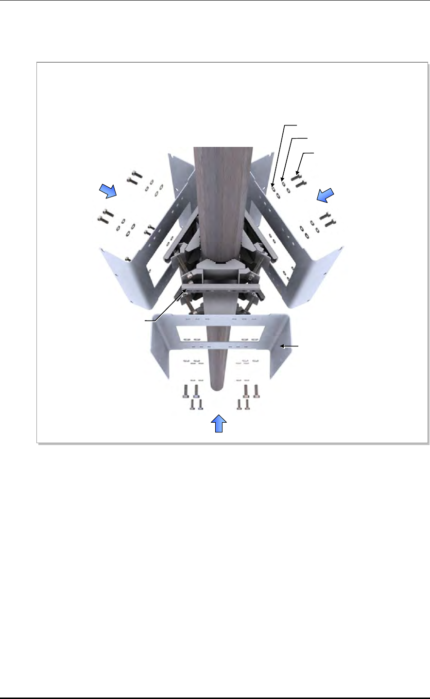
2) Fixing the RRH-2WB Unit Mounting Bracket to the RRH-2WB Fixing Support
Figure 2.24 Fixing Tower Type RRH-2WB (3)
Tighten the RRH-2WB unit mounting bracket to the RRH-2WB fixing supports with the M8 carriage bolts,
plane washers, spring washers, and hex. nuts.
M8 Hex. Nut
M8 Spring Washer
M8 Plane Washer
RRH-2WB Fixing Support
(Rear Side)
RRH-2WB Unit Mounting Bracket
M8 Carriage Bolt
Tower Angle
RRH-2WB Fixing Support
(Front Side)
CHAPTER 2. Installing System
2-26 © SAMSUNG Electronics Co., Ltd.
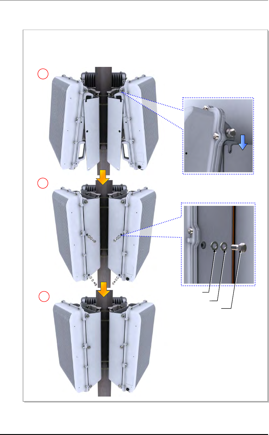
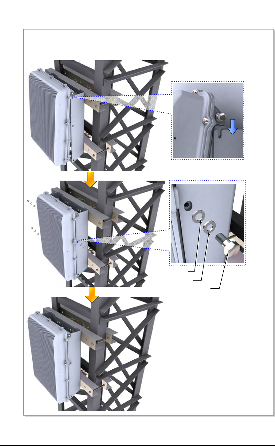
3) Fixing the RRH-2WB to the RRH-2WB Unit Mounting Bracket
Figure 2.25 Fixing Tower Type RRH-2WB (4)
Temporarily fix the M8 hex. bolt, plane washer, and spring washer loosely to the left/right fixing hole on the top
of the RRH-2WB. Hang the RRH-2WB to the hooking holes at the top of the RRH-2WB unit mounting bracket.
Then align the RRH-2WB with the fixing holes of the RRH-2WB unit mounting bracket and fix them firmly.
M8 × 15L Hex. Bolt
M8 Spring Washer
M8 Plane Washer
Mobile WiMAX/TD-LTE RRH-2WB Installation Manual/Ver.2.0
© SAMSUNG Electronics Co., Ltd. 2-27
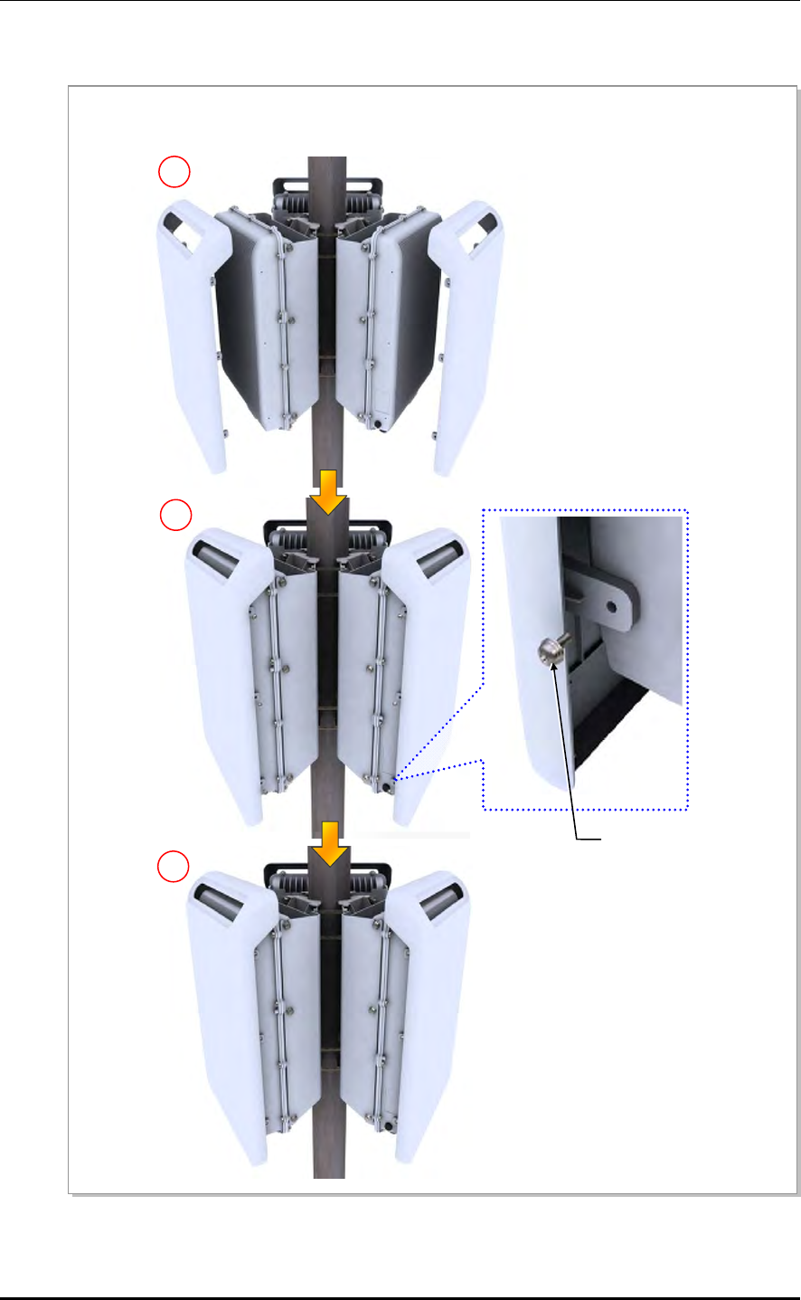
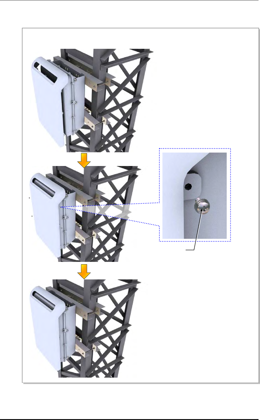
4) Assembling the Solar Shield to RRH-2WB
Figure 2.26 Fixing Tower Type RRH-2WB (5)
a) Align the solar shield cover with the fixing holes of the RRH-2WB and then fix them firmly using M5
SEMS screws.
M5 × 12L SEMS
CHAPTER 2. Installing System
2-28 © SAMSUNG Electronics Co., Ltd.
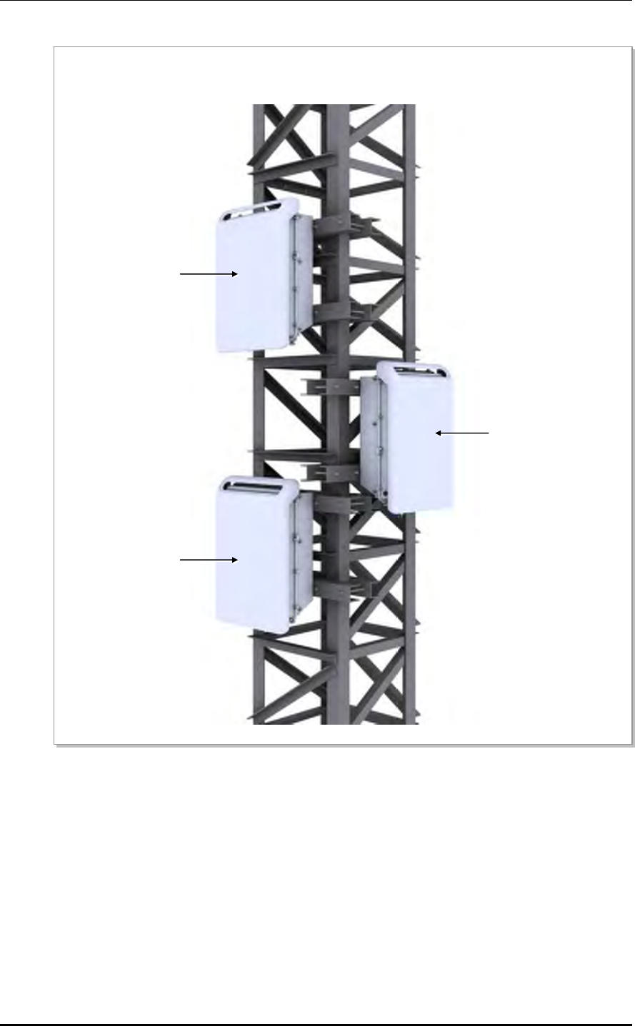
Figure 2.27 Fixing Tower Type RRH-2WB (6)
b) Attach RRH-2WB #1 and #2 to one side of the tower and RRH-2WB #3 to the other side
RRH-2WB #1
RRH-2WB #3
RRH-2WB #2
Mobile WiMAX/TD-LTE RRH-2WB Installation Manual/Ver.2.0
© SAMSUNG Electronics Co., Ltd. 2-29
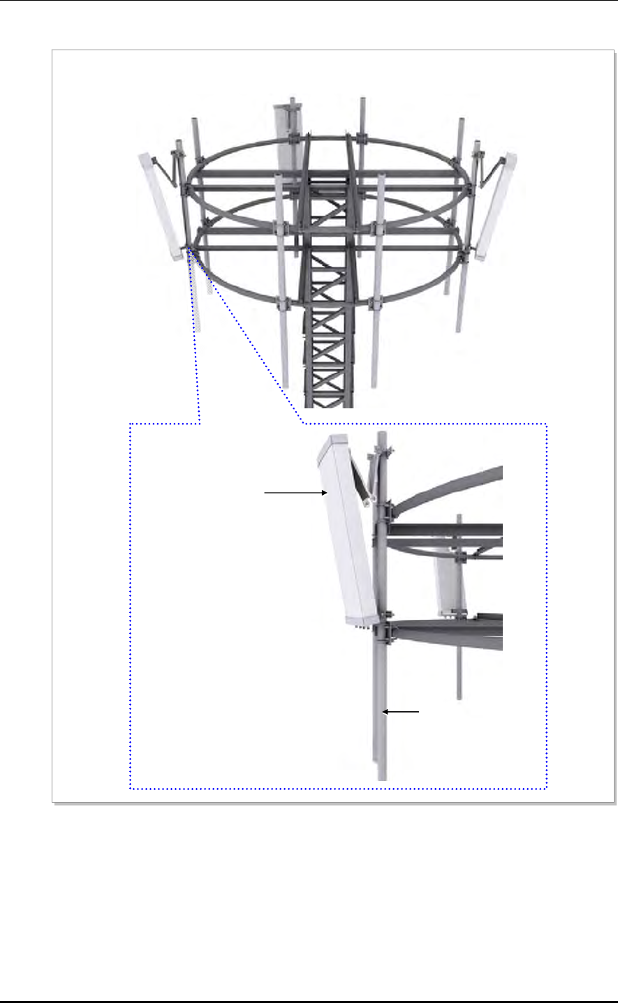
5) Fixing the Sector Antenna
Figure 2.28 Fixing Tower Type RRH-2WB (7)
a) Place the pipe fixing plate and antenna fixing pipe in their positions and fix them to the platform pipe
using M10 U-bolts.
A
ntenna Fixing Pipe
Pipe Fixing Plate
Platform Pipe
A
ntenna Fixing Pipe
Platform Pipe
Pipe Fixing Plate
M10 Hex. Nut
M10 Spring Washer
M10 Plane Washer
M10 U-Bolt
A
ntenna Fixing Pipe
M10 Hex. Nut
M10 Spring Washer
M10 Plane Washer
M10 U-Bolt
CHAPTER 2. Installing System
2-30 © SAMSUNG Electronics Co., Ltd.
Figure 2.29 Fixing Tower Type RRH-2WB (8)
b) Install a sector antenna (4T4R) to each antenna fixing pipe.
Sector Antenna (4T4R)
A
ntenna Fixing Pipe
Mobile WiMAX/TD-LTE RRH-2WB Installation Manual/Ver.2.0
© SAMSUNG Electronics Co., Ltd. 2-31
2.5 System Leveling
Leveling refers to compensating for the level difference on the floor that is generated
during floor work to install devices horizontally or vertically. Leveling can be carried out
using a vinyl hose, a balance weight, or a level.
However, levels are used for this system.
Leveling Using a Level
1) Attach a level to the top, left, and right of the system.
2) Adjust the system height so that the bubble in the level moves to the center of the
window. (In the case of a digital level, the LCD should indicate an even plane.)
3) Leveling is complete when the bubble stays at the window center in every level.
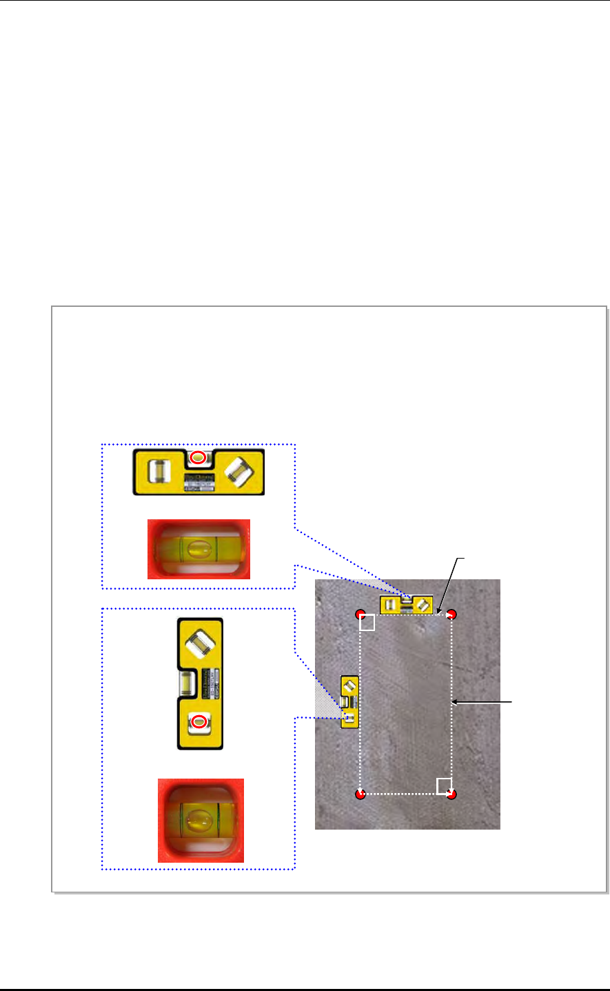
Figure 2.30 Leveling Test before Fixing Anchor Bolts
Vertical line
90°
90°
Horizontal line
Leveling Test for Wall Type System (Before Fixing the Anchor Bolt)
1) Before fixing the anchor bolts, draw a vertical and a horizontal between the markings of the anchor
bolts, as shown in the Figure below. Make the lines vertical/horizontal using a spirit level.
2) When the lines are not placed in vertical/horizontal, complying with the distance to fix the equipment,
modify the markings of the anchor bolts until the lines are placed in vertical/horizontal.
Measuring for horizontal section
Measuring for vertical section
CHAPTER 2. Installing System
2-32 © SAMSUNG Electronics Co., Ltd.
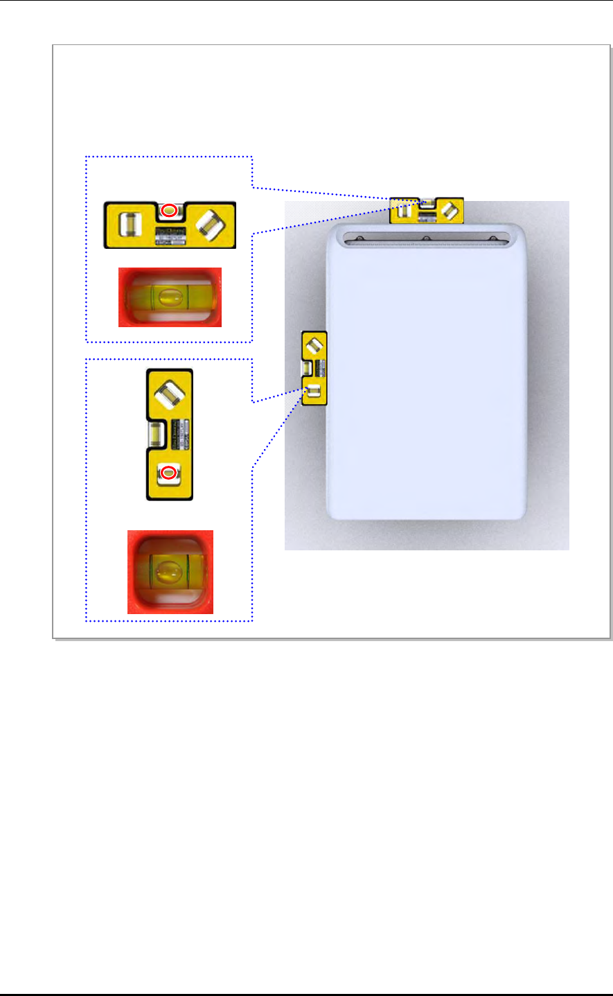
Figure 2.31 Leveling Test before Fixing System
3) After fixing the equipment, place a spirit level on the side and top of the equipment, test the vertical/
horizontal leveling.
4) If the leveling result shows that the equipment is not placed in vertical/horizontal, check and adjust the
drilling location, connection materials’ dimensions, and structures’ dimensions and then make the
Measuring Horizontal
Position
Measuring Vertical Position
Mobile WiMAX/TD-LTE RRH-2WB Installation Manual/Ver.2.0
© SAMSUNG Electronics Co., Ltd. 2-33
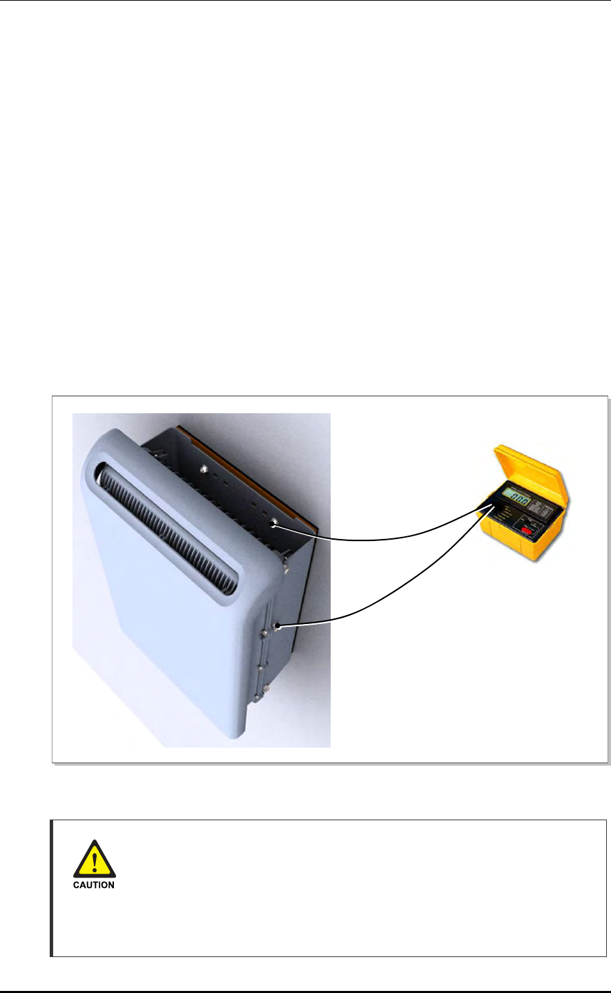
2.6 Insulation Test
When conducting an insulation test, it is advised to set the insulation tester to DC 500 V
and the insulation value is recommend as 100 MΩ or higher.
1) Connect a lead of an insulation tester to the Hex.bolt for fixing the RRH-2WB.
2) Connect another lead to the anchor bolt.
3) Measure the insulation resistance by using the insulation tester.
The insulation resistance should be over 100 MΩ.
If the measured resistance is less than 100 MΩ, the value indicates the insulation failure.
Thus, check the following and perform the insulation test again.
Check if the connection between the Hex.bolt for fixing the RRH-2WB and the anchor
bolt is proper. (Note that the anchor bolts must be shielded with an insulated bushing.)
Check if the insulated bushing is damaged.
Replace the insulator (insulated bushing, bakelite, rubber pad, etc.) or parts for fixing.
Figure 2.32 Schematic Diagram for Insulation Test
Precautions for Measuring Insulation Resistance
Since a high voltage is used for measuring insulation resistance, insulation
resistance should not be measured when the system is in operation. Make sure to
only measure the insulation resistance of the appointed part. Other components
such as the system’s internal components and the unit (system frame),
components of the communication cables, units, etc. should not be measured.
Measuring Instrument
of Insulation Resistance
Anchor Bolt
Hex.bolt for Fixing the
RRH-2WB

CHAPTER 2. Installing System
2-34 © SAMSUNG Electronics Co., Ltd.
This page is intentionally left blank.
Mobile WiMAX/TD-LTE RRH-2WB Installation Manual
© SAMSUNG Electronics Co., Ltd. 3-1
CHAPTER 3. Connecting Cables
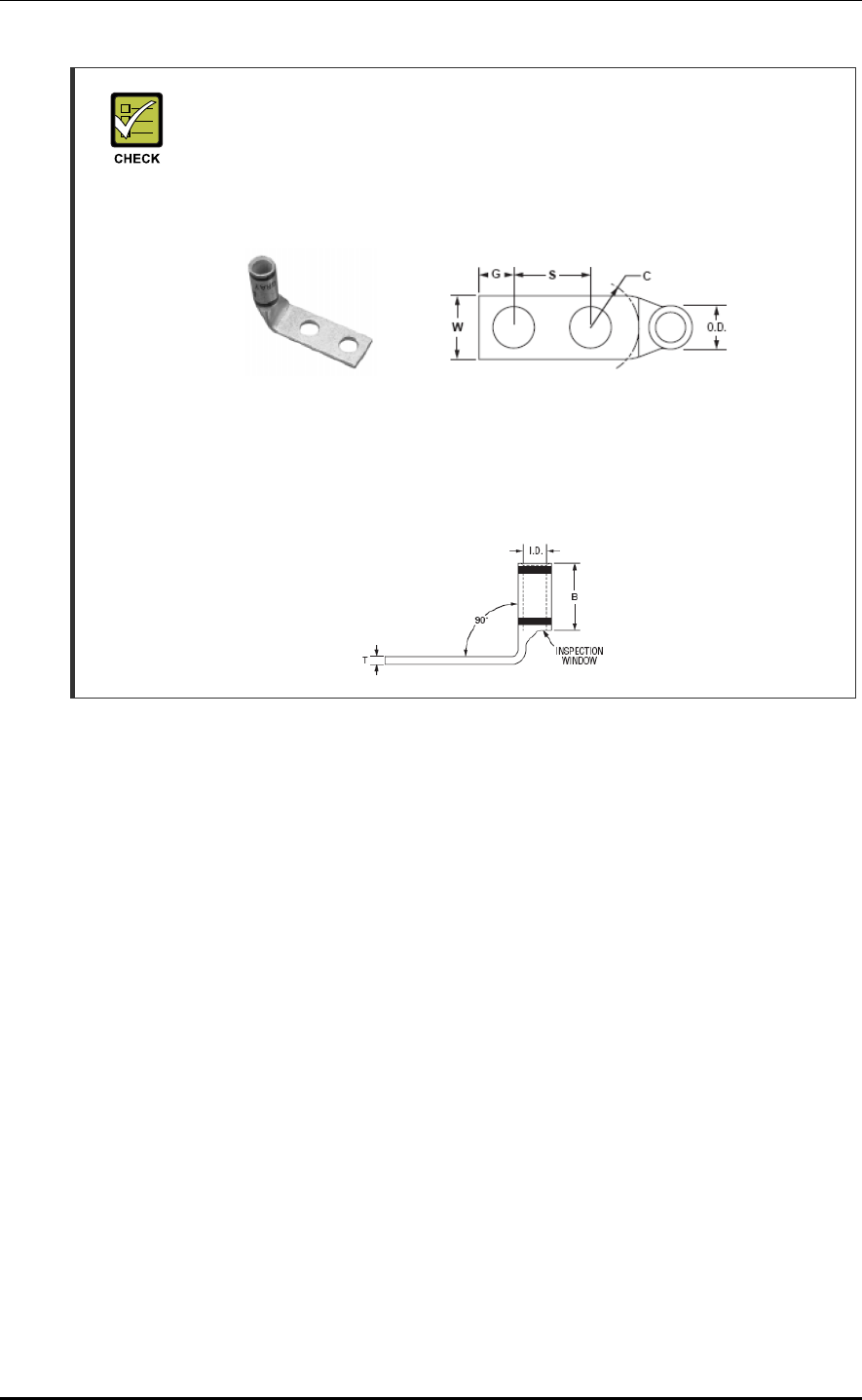
3.1 Work Flow for Cabling
The cabling sequence is as follows.
Figure 3.1 Work Flow for Cabling
Cabling Workflow
The sequence of cable cutting and installation of the cable workflow can be
changed depending on the field situation such as ‘cutting after installing’ or
‘installing after cutting’.
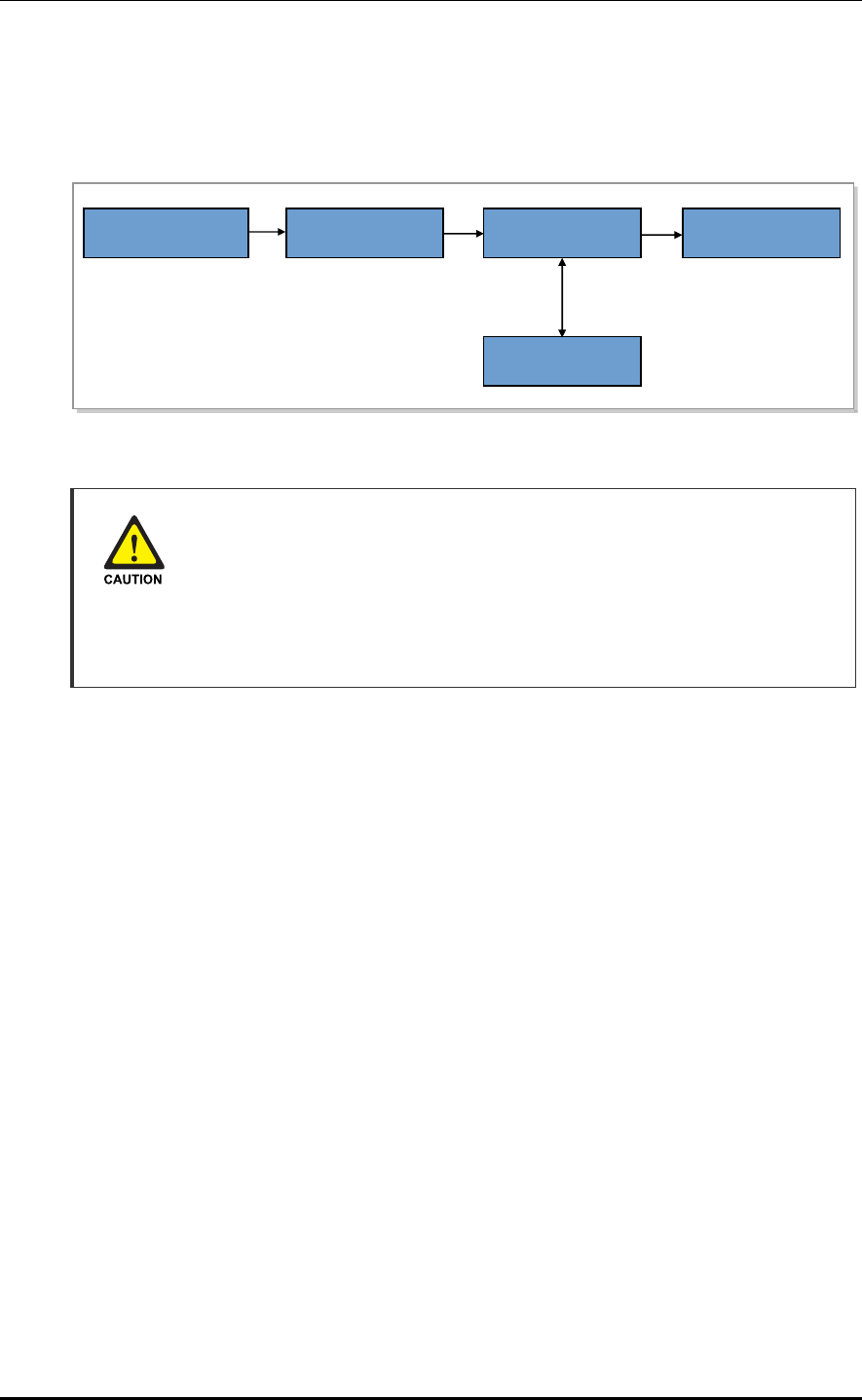
Considerations when Cutting the Cable after Installation
When cutting the cable after installation, make sure that the connector is
disconnected. Installation of the cable with the connector connected to the system
may cause contact failure or damage to the connector assembled to the system
and the cable due to cable tension or the operator’s mistakes.
Cable Installation
Cable Binding
Connector Attachment
Identification Tag Attachment
Connector Assembly
When assembling the
connector at the site
Cable Path Inspection
Cable Cutting

CHAPTER 3. Connecting Cables
3-2 © SAMSUNG Electronics Co., Ltd.
Cable Path Inspection
When installing a cable that connects between the rectifier, Main Ground Bar (MGB), and
backhaul device, etc. within the system, the cable path length and the cable installation
method, etc. must be inspected.
Follow these guidelines when inspecting the cabling path.
A minimum cable length must be selected provided that it does not affect the cable
installation and maintenance.
The cable must be placed in a location where it will not be damaged by external
factors. (power line, flooding, footpaths, etc.)
In areas where the cable may be damaged by external factors, ensure that measures are
taken to prevent damage to the cable. (cable tray, ducts, flexible pipe, etc.)
Cable Cutting
Measure the exact distance, carefully checking the route, and cut the cable using a cutting tool.
Follow these guidelines when cutting the cable.
Cut the cable to the length determined in the Cable Path Inspection step.
Use a dedicated cable cutting tool.
Cut the cable at right angles.
Be careful to keep the cable away from any moisture, iron, lead, dust or other foreign
material when cutting. Remove any foreign material attached to the cable using
solvent and a brush.
Cable Installation
Cable installation involves running the cable along the cabling path to the target connector
of the system or an auxiliary device after cable path inspection and cable cutting have been
completed.
Follow these guidelines when installing a cable.
Be careful not to damage the cable.
If the cable is damaged, cut out the damaged section before installing.
When installing the cable over other cables, make sure the cable is installed on the
other cables. Pay more attention to the vertical and horizontal cross sections where the
cables are usually reversed.
Always use the maximum curvature radius possible, and make sure that the minimum
curvature radius specification is complied with.
If the cable needs to be protected, use a PVC channel, spiral sleeve, flexible pipe, and
cable rack, etc.

Mobile WiMAX/TD-LTE RRH-2WB Installation Manual/Ver.2.0
© SAMSUNG Electronics Co., Ltd. 3-3
Table 3.1 Recommended Minimum Allowed Cable Bend Radius
No Type Recommended Minimum Allowed
Cable Bend Radius Remark
1 GV/CV/FR-8 8 times of the cable external diameter 0.6/1 KV Cable
2 Optic Cable 20 times of the cable external diameter -
3 UTP/FTP/S-FTP Cable 4 times of the cable external diameter PVC/LSZH, 4 Pair
4 1/2 in. Feeder Line (Indoor) 32 mm (1.26 in.) RFS, LS
5 1/2 in. Feeder Line (Outdoor) 125 mm (4.92 in.) RFS, LS
6 7/8 in. Feeder Line (Outdoor) 250 mm (9.84 in.) RFS, LS
7 1-1/4 in. Feeder Line (Outdoor) 380 mm (14.96 in.) RFS, LS
8 1-5/8 in. Feeder Line (Outdoor) 500 mm (19.69 in.) RFS, LS
9 LMR-400 25.4 mm (1 in.) Installation
101.6 mm (4 in.) Repeated
10 RG-316D 15 mm (0.59 in.) -
※ If the allowed cable bend radius is specified by the manufacturer, comply with the bend radius specified.
Cable Binding
Cable binding involves fixing and arranging an installed cable using binding strings, cable
ties, binding lines, and ram clamps, etc.
Follow these guidelines when binding a cable.
Be careful not to damage the cable during binding.
Use appropriate cable binding tools according to the target location (indoor or outdoor,
etc.) and the use of the cable (power supply cable, optical cable, feeder line, etc.).
Do not let the cutting section of a cable tie and binding line, etc. be exposed to the
outside. This may cause damage to cables or personal injury. Make sure that the
cutting sections of cables are not exposed to the outside.
If there is a danger that contact failure may occur in a connector connection due to
tension, install the cable as short as possible.
Connector Attachment
Connector attachment involves assembling a connector to an installed cable or to a device
on the site.
Follow these guidelines when attaching a connector.
Make sure you are fully aware of the connector assembly method before assembling a
connector. Assemble the connector in accordance with its pin map.
Each connector has a hook to prevent its core positions from being changed.
Check the corresponding grooves before connecting a connector to another connector.
Trim the remaining string of any knot in a binding string so that the knot does not loosen.
CHAPTER 3. Connecting Cables
3-4 © SAMSUNG Electronics Co., Ltd.
Use a heat shrink tube at a connector connection for cables that are installed outdoor,
such as feeder lines, to prevent water leakage and corrosion from occurring at the part
exposed to the outside.
Connect each cable of the connector assembly in a straight line.
Be careful when connecting a cable so that contact failure does not occur at a
connector connection due to tension.
Identification Tag Attachment
Identification tag attachment involves attaching a marker cable tie, nameplate, and label,
etc. to the both ends of a cable (connections to a connector) to identify its use and cabling path.
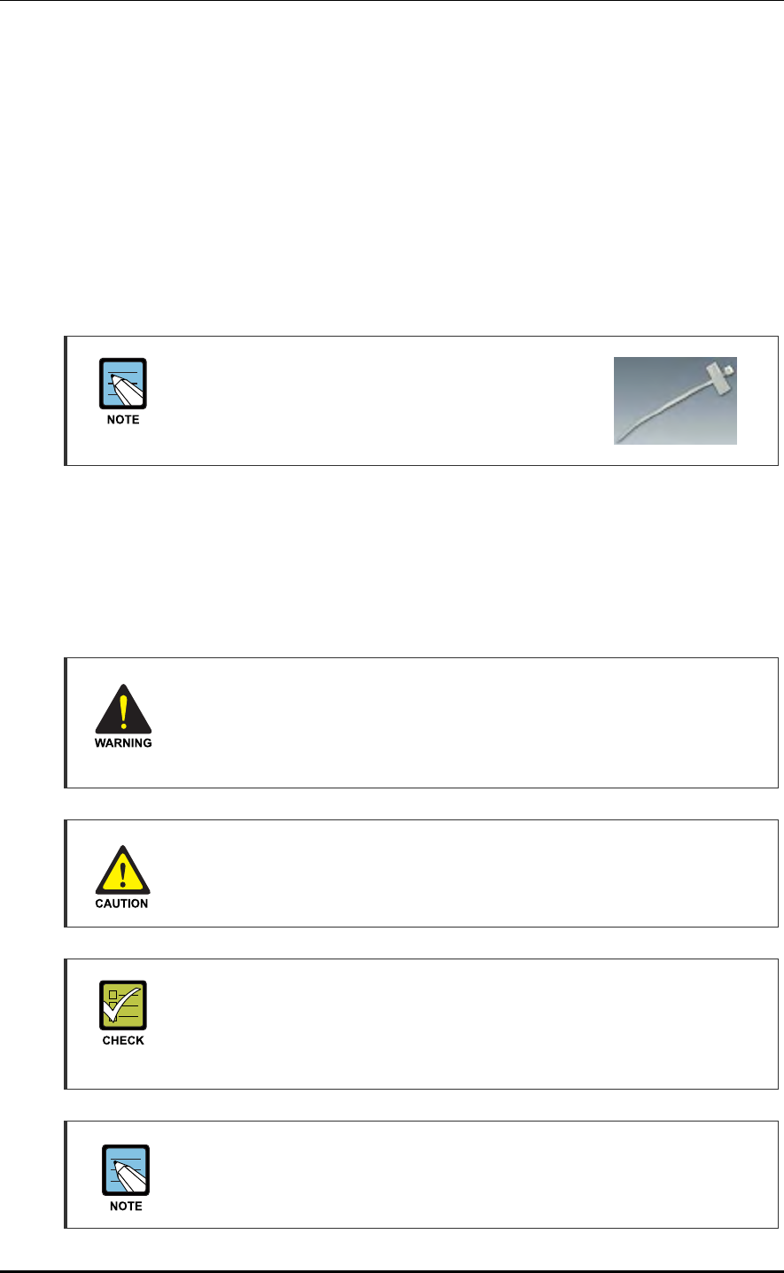
Marker Cable Tie
On the marker cable tie, a label can be attached.
The appearance and specification may differ depending
on the type and manufacturer.
Follow these guidelines when attaching an identification tag.
When installing a cable outdoor, use relief engraving and coated labels, etc. to prevent
the markings from being erased.
Since the form and attachment method for identification tags are different for each
provider, consult with the provider before attaching them.
Connecting Ground Cable
In cabling, the connection of cables without the connection to the ground cable
may cause the damage of the equipment or the bodily injury of the worker.
Connect the ground cable first.
Cable Work Sequence
When performing cable work for the system, proceed with the ground work before any
other work to prevent errors occurring due to static electricity and other reasons.
Cable Installation Checklist
When installing, take care not to overlap or tangle the cables; also, consider
future expansion. Install the DC power cable and data transmission cable away
from the AC power cable to prevent electromagnetic induction.
Cable Works
The cable works require the knowledge for the cabling works such as cable
installation/tying.
Mobile WiMAX/TD-LTE RRH-2WB Installation Manual/Ver.2.0
© SAMSUNG Electronics Co., Ltd. 3-5
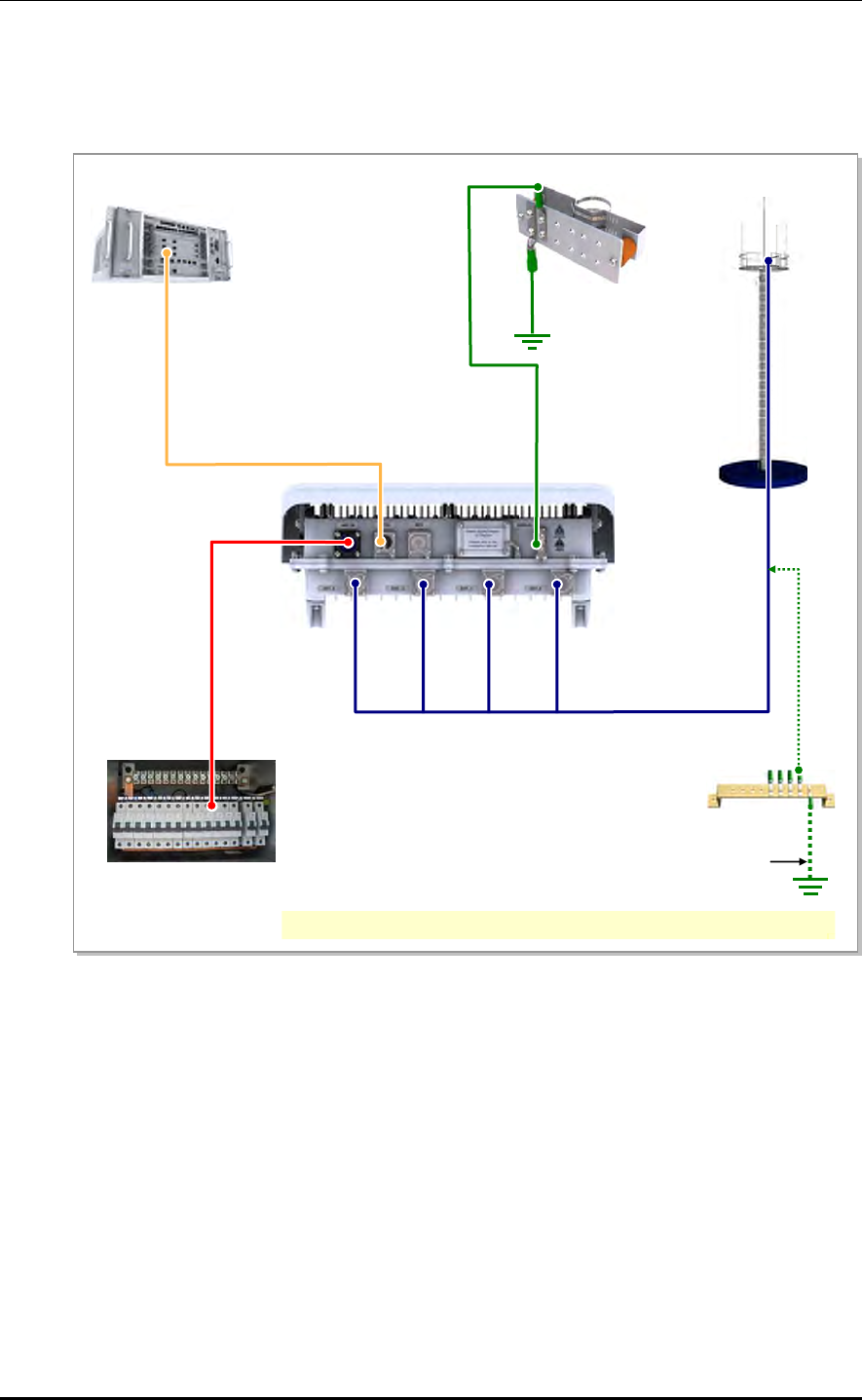
3.2 Cabling
The cabling diagram of the RRH-2WB is as follows:
Figure 3.2 Cabling Diagram
1) RRH-2WB Frame
Ground Cable
[DU]
[Rectifier]
[RF Antenna]
[MGB]
4) RF Antenna Cable
TGB Ground Cable
[
TGB
]
Ground Kit
※ TGB and Ground Kit are used when using the 7/8 in. feeder line or more.
3) Optic Cable (for DU)
2) Power Cable

CHAPTER 3. Connecting Cables
3-6 © SAMSUNG Electronics Co., Ltd.
Table 3.2 RRH-2WB Connecting Cable
From To Cable
RRH-2WB MGB 1) RRH-2WB Frame Ground Cable
: AWG 10, GV 4 mm2 × 1C
Rectifier 2) Power Cable
: AWG8, CV 6 mm2 × 2C
DU 3) Optic Cable
: ODC-4 to LC/PC, Single Mode
RF Antenna 4) RF Antenna Cable
: 1/2 in. Feeder Line, 7/8 in. Feeder Line
Underground ground MGB AWG4/0, GV 95 mm2 × 1C
(However, this can be different, defending on the standard
of service provider)
TGB AWG4/0, GV 95 mm2 × 1C
(However, this can be different, defending on the standard
of service provider)
Mobile WiMAX/TD-LTE RRH-2WB Installation Manual/Ver.2.0
© SAMSUNG Electronics Co., Ltd. 3-7
3.3 Grounding
Grounding is required for protecting complex electronic or electric systems such as power
system, communication system, and control system from lightning, over-current, over-
voltage, and electric noise. Thus, the systems can operate properly and protect human life
from electrical shock. Ground equipment minimizes the electrical potential of the
electronic device to that of the ground, which is zero electrical potential, so that it can
prevent the device from occurring electrification.
The purposes of the ground construction are as follows:
To prevent human life and the system from over-current, over-voltage, and lightning
To provide a discharge path for surge voltage generated by lightning and power switch
To protect the system from static electricity
To eliminate or minimize the high-frequency potential in the system housing
To provide a conductor for the balance and stability of high-frequency current
To stabilize the potential of the circuit against the ground
Connecting Ground Cable
In cabling, the connection of cables without the connection to the ground cable
may cause the damage of the equipment or the bodily injury of the worker.
Connect the ground cable first.
CHAPTER 3. Connecting Cables
3-8 © SAMSUNG Electronics Co., Ltd.
3.3.1 Grounding the System
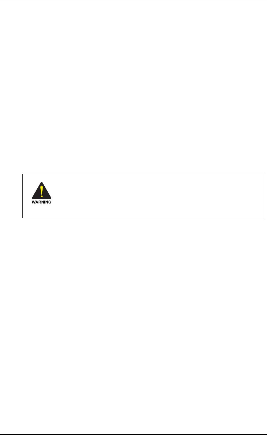
RRH-2WB Grounding
The way to connect the ground cable of RRH-2WB is as follows:
1) Install a ground cable (AWG10, GV 4 mm2 × 1C) from the MGB to the ground
terminal at the bottom of the RRH-2WB.
2) Fix a 4 mm2 pressure terminal and a heat shrink tube at the cable end.
Pressure terminal: 2 Hole, 90°, hole diameter: 6.3 mm (0.25 in.), hole distance
16 mm (0.63 in.)
Heat shrink tube: Green
3) Align the pressure terminal fixed to the cable with the fixing holes on the RRH-2WB’s
grounding terminal, and fix it with M6 SEMS. Apply a torque of 20~30 kgf.cm (1.45~
2.17 lbf·ft).
Figure 3.3 Connection of the RRH-2WB Ground Cable
Heat Shrink Tube
(Green)
RRH-2WB
Ground Cable
(AWG10, GV 4 mm2 × 1C)
From MGB (Main Ground Bar)
Detail ‘A’
‘A’
M6 × 12L SEMS
4 mm2 Pressure Terminal
Mobile WiMAX/TD-LTE RRH-2WB Installation Manual/Ver.2.0
© SAMSUNG Electronics Co., Ltd. 3-9
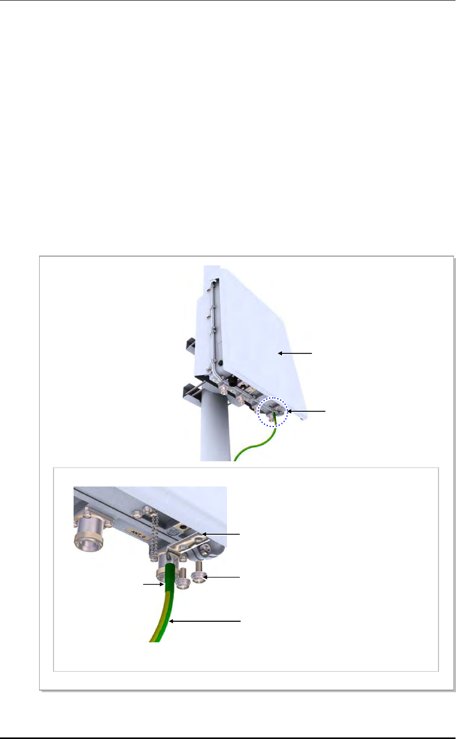
Pressure Terminal for RRH-2WB Frame Grounding
As for the pressure terminal or the cable, the UL certified products or equivalent
should be used.
Ex) Manufacturer-Panduit
4 mm2 Pressure Terminal: LCD10-14AF-L
When connecting the pressure terminal to a cable, remove the cable sheath
where the pressure terminal is connected, and then push the cable all the way to
the end of the cable lead-in part.
Check the position of the coaxial cable through the inspection window of the
pressure terminal before compressing it with a compressor.
CHAPTER 3. Connecting Cables
3-10 © SAMSUNG Electronics Co., Ltd.
3.4 Power Construction
The power construction is to supply the power inside the exchange. The power supply
device is configured as follows:
Figure 3.4 Power Equipment Diagram
Handling the Power Cable
- Handling the power cable incorrectly may damage the rack or cause an electric
shock through the cable. Ensure the power switch on the rectifier or the system
is turned off before handling the power cable.
- The fixing materials for power cable must be tightly secured to prevent electrical
accidents.
3.4.1 Installing the Power Cable
1) Install a power cable (AWG8, CV 6 mm2 × 2C) covered with flexible pipes from the
rectifier to the power port at the bottom of the RRH-2WB.
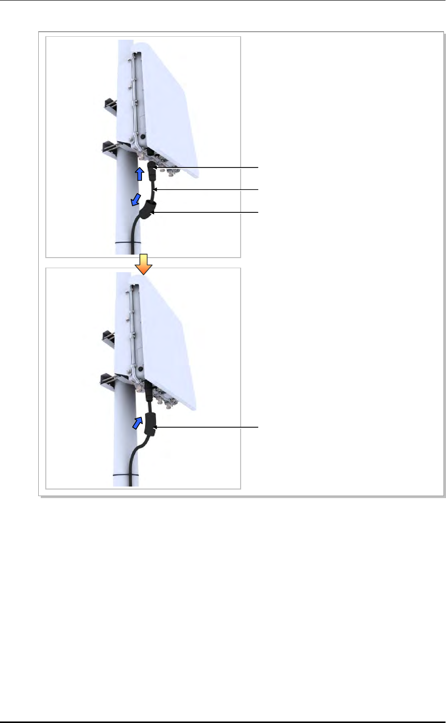
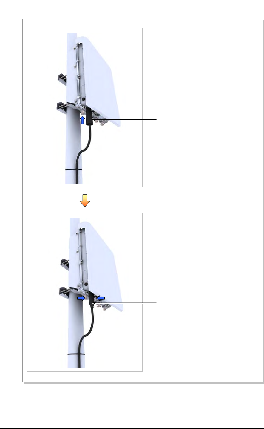
2) Fit a water-proof power connector to the installed power cable (AWG8, CV 6 mm2 ×
2C). Refer to the assembly manual enclosed in the connector box for how to assemble
the connector.
3) Fit a cut heat shrink tube to the power cable before connecting the cable to the system
power port.
4) Connect the cable fitted with the power connector to the power port at the bottom of
the system.
5) When the cable connection is completed, contract the heat shrink tube (jelly type)
using a heating gun so that the flexible pipes and the connector unit are well fixed.
(Finish using silicon if necessary.)
A
C
AC Distributor Commercial Power DC System
Rectifier
Battery
Mobile WiMAX/TD-LTE RRH-2WB Installation Manual/Ver.2.0
© SAMSUNG Electronics Co., Ltd. 3-11
Figure 3.5 Installing the RRH-2WB Power Cable (1)
Power Connector
(Amphenol, CJE-AL06M25U15-2S)
Power Cable
(AWG8, CV 6 mm2 × 2C, -48 V DC)
Heat Shrink Tube (Jelly Type, Black)
Heat Shrink Tube (Jelly Type, Black)
CHAPTER 3. Connecting Cables
3-12 © SAMSUNG Electronics Co., Ltd.
Figure 3.6 Installing the RRH-2WB Power Cable (2)
Heat Shrink Tube (Jelly Type, Black)
Heat Shrink Tube (Jelly Type, Black)

Mobile WiMAX/TD-LTE RRH-2WB Installation Manual/Ver.2.0
© SAMSUNG Electronics Co., Ltd. 3-13
[RRH-2WB Power Cable Side]
C
D
Circuit Breaker Installation
Circuit breaker of slow blow type should be installed to the power line which is
connected from the rectifier (or power distributor) to the system in order to supply
the power stably. The capacity of -48 VDC circuit breaker is 20 A.
Power cable
In case of using AWG8 (6 mm2 × 2C) power cable, it is applicable up to 70 m
(299.66 ft). When the distance is 70 m (299.66 ft), followings should be
considered.
- Do not rapid ON/OFF (within one second): The voltage loss value caused by the
cable resistance loss is 3 V, and the RRH-2WB could be damaged by the
counter electromotive force caused by the cable inductance.
- The battery’s life could be shorten: The RRH-2WB could be off in spite the
battery remains. (When the battery capacity is designed within one hour)
- Do not use the power cables linked: Using the power cables linked each other,
the loss will be increased.
Figure 3.7 Power Cable Connector
Table 3.3 Amphenol CJE-AL06M25U15-2S Power Connector Pin Map
Pin No. Description Power Cable Color (CV 6 mm2 × 2C) Heat Shrink Tube Color
C -48 V Black Blue
D Return White Red
Power Cable Color
In the table above, the cable color is based on the inner wire of the CV 6 mm2 ×
2 core cable. The color of the inner wires may vary depending on the type and
manufacturer of the cable used.

CHAPTER 3. Connecting Cables
3-14 © SAMSUNG Electronics Co., Ltd.
3.5 External Interface Construction
3.5.1 Cable Connection between the DU and the RRH-2WB
The RRH-2WB is a unified RF module interfacing remotely with the DU through an
optical cable. It is located at the front end of the antenna.
Cable connection between the DU and the RRH-2WB is as shown below.
1) Install an optic cable from the DU to the optic port at the bottom of the RRH-2WB.
2) Fit a cut heat shrink tube to the optic cable before connecting the cable to the system
optic port.
3) Connect the optic cable connector (ODC type) to the optic port at the bottom of the
system.
4) When the cable connection is completed, contract the heat shrink tube (jelly type)
using a heating gun so that the flexible pipes and the connector unit are well fixed.
(Finish using silicon if necessary.)
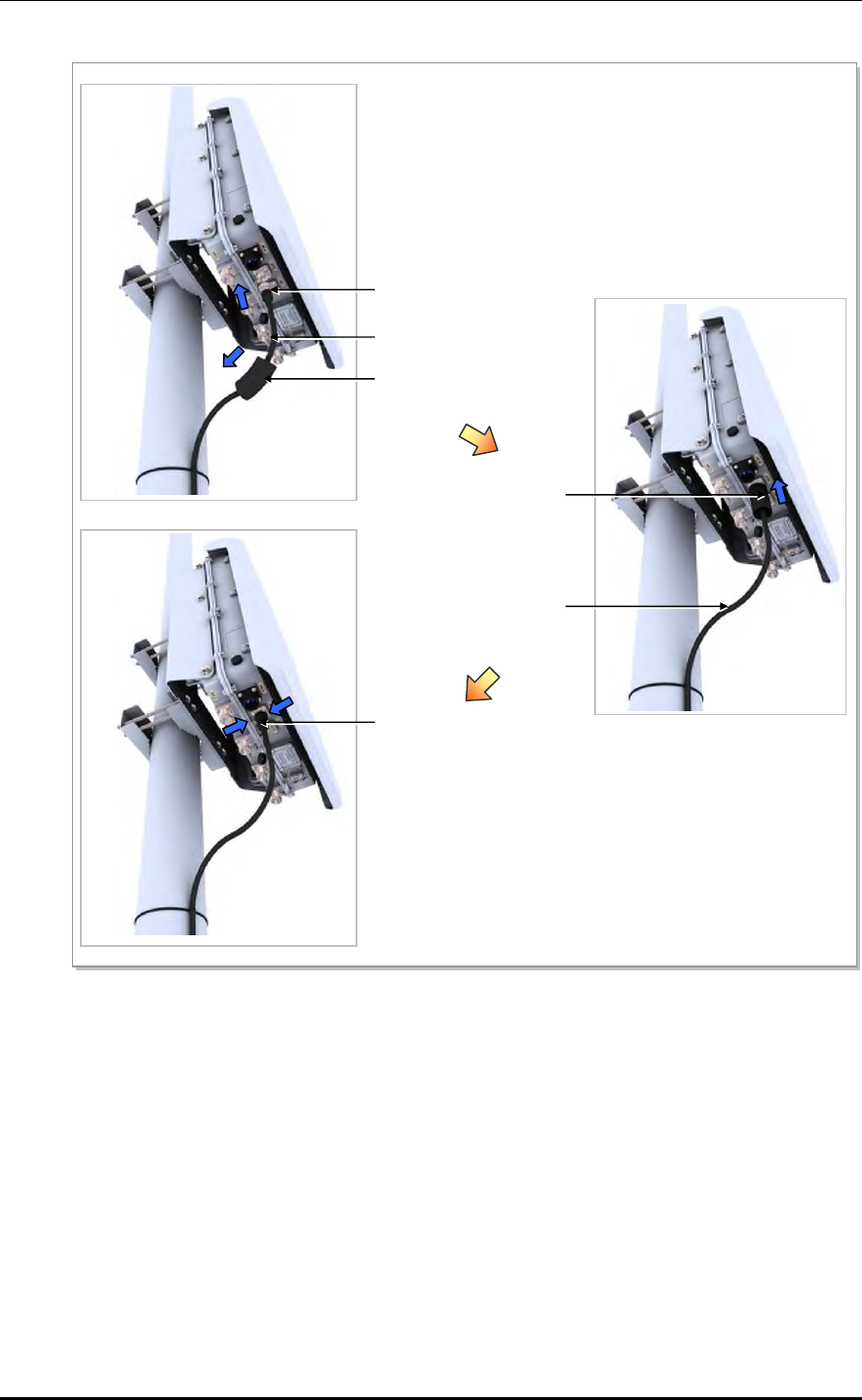
Mobile WiMAX/TD-LTE RRH-2WB Installation Manual/Ver.2.0
© SAMSUNG Electronics Co., Ltd. 3-15
Figure 3.8 Cable connection between the DU and the RRH-2WB (Optical connection)
Optic Connector
(ODC-Outdoor connector)
Heat Shrink Tube
(Jelly Type, Black)
Optic Cable (Single Mode)
Heat Shrink Tube
(Jelly Type, Black)
Optic Cable (Single Mode)
Heat Shrink Tube
(Jelly Type, Black)
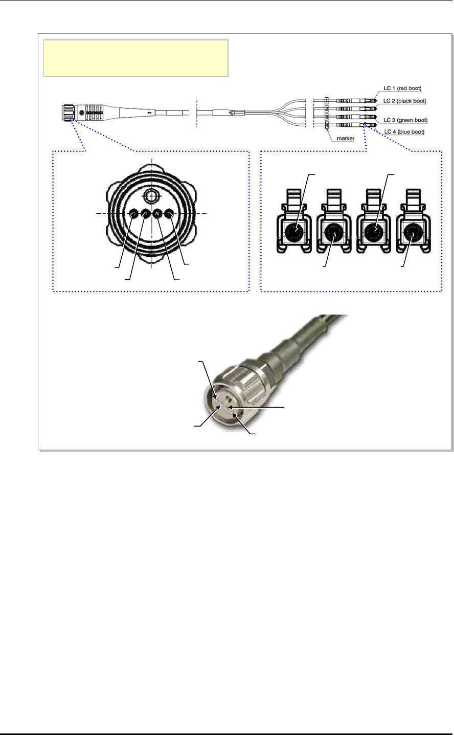
CHAPTER 3. Connecting Cables
3-16 © SAMSUNG Electronics Co., Ltd.
Figure 3.9 Optic Cable Connector between DU and RRH-2WB_RRH-2WB side
[RRH-2WB-side Connector: ODC-4 (ODCP-Z/M-A300-04)] [DU-side Connector: FLC-Z/K-A006]
[Cable: 04-E9/FSN (ZN)Z-G55]
[Huber + Suhner]
Full Part No.: 09Z04FG0-J3/85-5-10[XX]NN
※ XX is cable length. (10: 10 meter)
LC 1 LC 3
LC 2 LC 4
Pin 1: Blue
Pin 2: Green
Pin 3: Black
Pin 4: Red
Pin 4 (LC 1): Red
Pin 3 (LC 2): Black Pin 1 (LC 4): Blue
Pin 2 (LC 3): Green
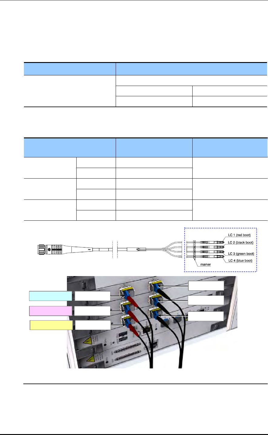
Mobile WiMAX/TD-LTE RRH-2WB Installation Manual/Ver.2.0
© SAMSUNG Electronics Co., Ltd. 3-17
Mobile WiMAX Only Operation Mode (4T4R)
Optic cable between RRH-2WB and DU for Mobile WIMAX only operation mode is as
follows:
Table 3.4 Cable Spec for Mobile WiMAX Only Operation Mode
Cable type DU Side (LC)
ODC-4 to LC Cable For 1st Carrier
Red Green
Primary Secondary
Table 3.5 Optic Connector Pin Map between RRH-2WB and DU for Mobile WiMAX Only
Operation Mode
DU Port LC Connector Boot Color
(Cable Marker) RRH-2WB
MRA-F #0 L0 Red (LC1) RRH-2WB #0
L1 Black (LC2)
MRA-F #1 L0 Red (LC1) RRH-2WB #1
L1 Black (LC2)
MRA-F #2 L0 Red (LC1) RRH-2WB #2
L1 Black (LC2)
RRH-2WB #0
RRH-2WB #1
RRH-2WB #2
LC 1 (Red)
LC 1 (Red)
LC 1 (Red)
LC 2 (Black)
LC 2 (Black)
LC 2 (Black)
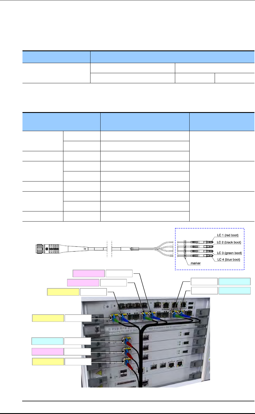
CHAPTER 3. Connecting Cables
3-18 © SAMSUNG Electronics Co., Ltd.
WiMAX + TD-LTE Dual Mode (2T2R)
Optic cable between RRH-2WB and DU for WIMAX + TD-LTE dual mode is as follows:
Table 3.6 Cable Spec for WIMAX + TD-LTE Dual Mode
Cable type DU Side(LC)
ODC-4 to LC Cable WiMAX @ ANT0/ANT1 LTE @ ANT2/ANT3
Red (LC1) Green (LC3) Blue (LC4)
Table 3.7 Optic Connector Pin Map between RRH-2WB and DU for WIMAX + TD-LTE Dual
Mode
DU Port LC Connector Boot Color
(Cable Marker) RRH-2WB
MRA-L A0 Green (LC3) RRH-2WB #0
A1 Blue (LC4)
MRA-F #0 L0 Red (LC1)
MRA-L B0 Green (LC3) RRH-2WB #1
B1 Blue (LC4)
MRA-F #1 L0 Red (LC1)
MRA-L C0 Green (LC3) RRH-2WB #2
C1 Blue (LC4)
MRA-F #2 L0 Red (LC1)
RRH-2WB #0
RRH-2WB #1
RRH-2WB #2
LC 1(Red)
LC 1(Red)
LC 1(Red)
LC 3(Green) RRH-2WB #0
LC 4(Blue)RRH-2WB #0
LC 3(Green)
RRH-2WB #1
LC 4(Blue)RRH-2WB #1
LC 3(Green) RRH-2WB #2
LC 4(Blue) RRH-2WB #2

Mobile WiMAX/TD-LTE RRH-2WB Installation Manual/Ver.2.0
© SAMSUNG Electronics Co., Ltd. 3-19
Warning for Laser Beam Running through Optical Cables
In the system, the laser beam emitting light runs through the optical cable.
The exposure of the laser beam on worker’s eye may cause serious injury so that
it should be handled with care.
Connecting the Optic Cable
Before connecting the optical cable, check if the cutting section of the connector
core is soiled. Be careful to keep the cutting section away from dust or foreign
material. If the cable is soiled with foreign material, do not blow to remove them.
Make sure to clean the connector in accordance with the cleaning directions for
the optic cable. Refer the ‘ANNEX D’.
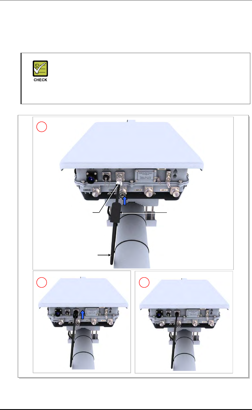
CHAPTER 3. Connecting Cables
3-20 © SAMSUNG Electronics Co., Ltd.
3.5.2 Cable Connection of RET
Below is the method for connecting the Remote Electrical Tilting (RET) cable to control
the antenna tilting angle remotely.
RET
- When applying 27 VDC voltage, a current of 1 A or less must be supplied to the
RET from the RRH-2WB.
- For the external material of the RET, metal without vent hole or the UL certificated
material must be use.
Figure 3.10 Cable Connection of RET
RET Connecto
r
(Samwoo, SU-20SP-8P)
RET Cable
Heat Shrink Tube
(Jelly Type, Black)
1
2 3
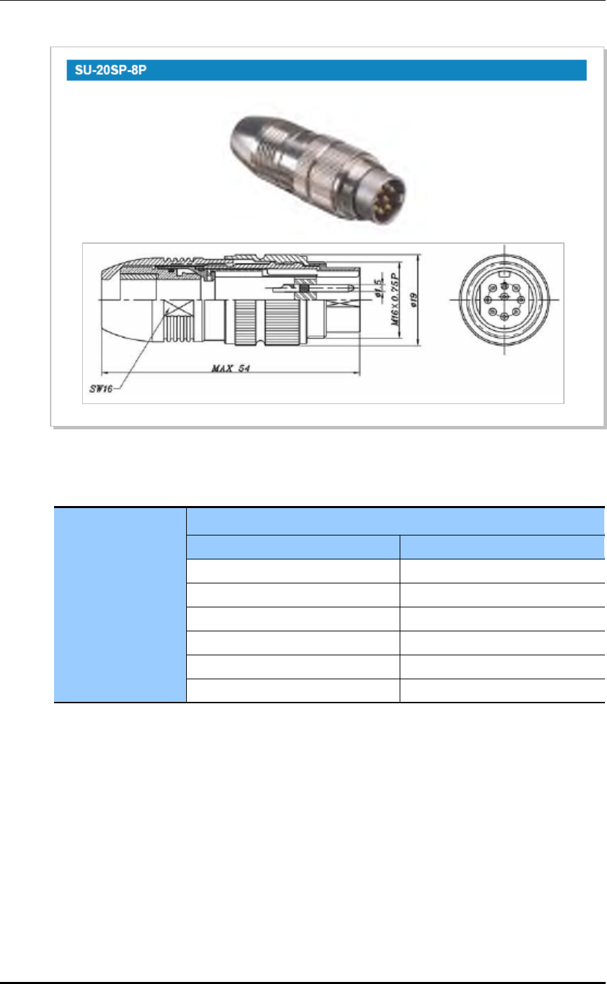
Mobile WiMAX/TD-LTE RRH-2WB Installation Manual/Ver.2.0
© SAMSUNG Electronics Co., Ltd. 3-21
Figure 3.11 RET Cable Connector
Table 3.8 RET Cable-side Connector Pin Map
RET Connector
Samwoo, SU-20SP-8P
Pin Function
3 RS485B
4 DGND
5 RS485A
6 +28 V
7 +28 V RTN
1, 2, 8 NC
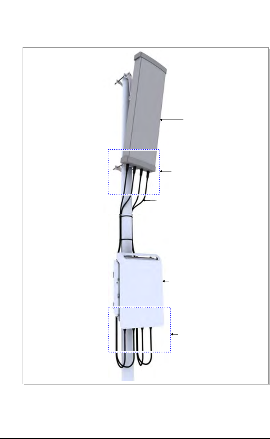
CHAPTER 3. Connecting Cables
3-22 © SAMSUNG Electronics Co., Ltd.
3.5.3 Connection of Feeder Cable
Connect a feeder cable between the RRH-2WB and the sector antenna as follows.
Figure 3.12 Feeder Line Connection Diagram
1/2 in. Feeder line
‘B’
Sector Antenna
RRH-2WB
‘A’
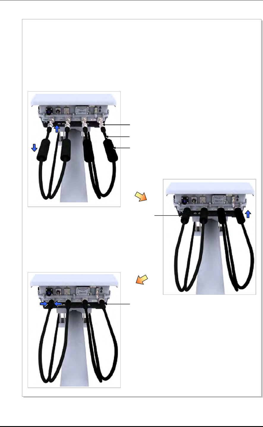
Mobile WiMAX/TD-LTE RRH-2WB Installation Manual/Ver.2.0
© SAMSUNG Electronics Co., Ltd. 3-23
Figure 3.13 Connection of Feeder Cable (Detail A)
1) From the 1/2 in. jumper ass’y between RRH-2WB and the RF antenna 1/2 in. jumper ass’y, install one
end of the cable, which the miniature Din-type male connector is connected to, to the RF port at the
bottom of RRH-2WB.
2) Attach the heat shrink tube (jelly type) for finishing to the Jumper cable, and connect the miniature Din-
type male connector to the RF port.
3) After connecting the connector, finish the connection with a heat shrink tube (jelly type).
Detail ‘A’
Miniature Din Type- Male Connector
(For 1/2 in. Feeder Line)
Heat Shrink Tube (Jelly Type, Black)
RF Cable (1/2 in. Feeder Line)
Heat Shrink Tube (Jelly Type, Black)
Heat Shrink Tube (Jelly Type, Black)
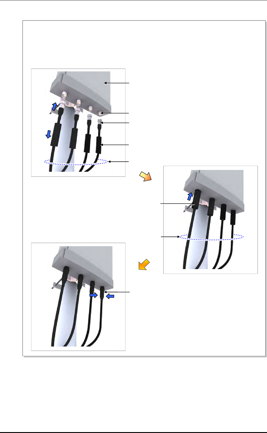
CHAPTER 3. Connecting Cables
3-24 © SAMSUNG Electronics Co., Ltd.
Figure 3.14 Connection of Feeder Cable (Detail B)
N Type-Male Connector For 1/2 in. Feeder Line
Heat Shrink Tube (Jelly Type, Black)
1/2 in. Feeder Line
A
ntenna Connector (N Type-Female)
Detail ‘B’
Sector Antenna (4T4R)
Heat Shrink Tube (Jelly Type, Black)
1/2 in. Feeder Line
Heat Shrink Tube (Jelly Type, Black)
4) Attach the heat shrink tube (jelly type, black) for finishing to the other end of the 1/2 in. jumper ass’y
connected to the RRH-2WB’s RF port, and connect the N-type male connector to the sector antenna’s port.
5) After connecting the connector, finish the connection with a heat shrink tube (jelly type, black).

Mobile WiMAX/TD-LTE RRH-2WB Installation Manual/Ver.2.0
© SAMSUNG Electronics Co., Ltd. 3-25
Checking the Antenna/Arrestor/Line Amplifier Connector Specs
The connector specifications may differ depending on the supplier and the
manufacturer of antenna/arrestor/line amplifier. Check the specifications of the
antenna/arrestor/line amplifier before preparing materials. Even, the same kind of
connectors may have different specifications depending on the cable, so check
whether the connector can be applied to the cable to be used.
Ex) Din Type-Male: 1/2 in. for feeder line, 7/8 in. for feeder line
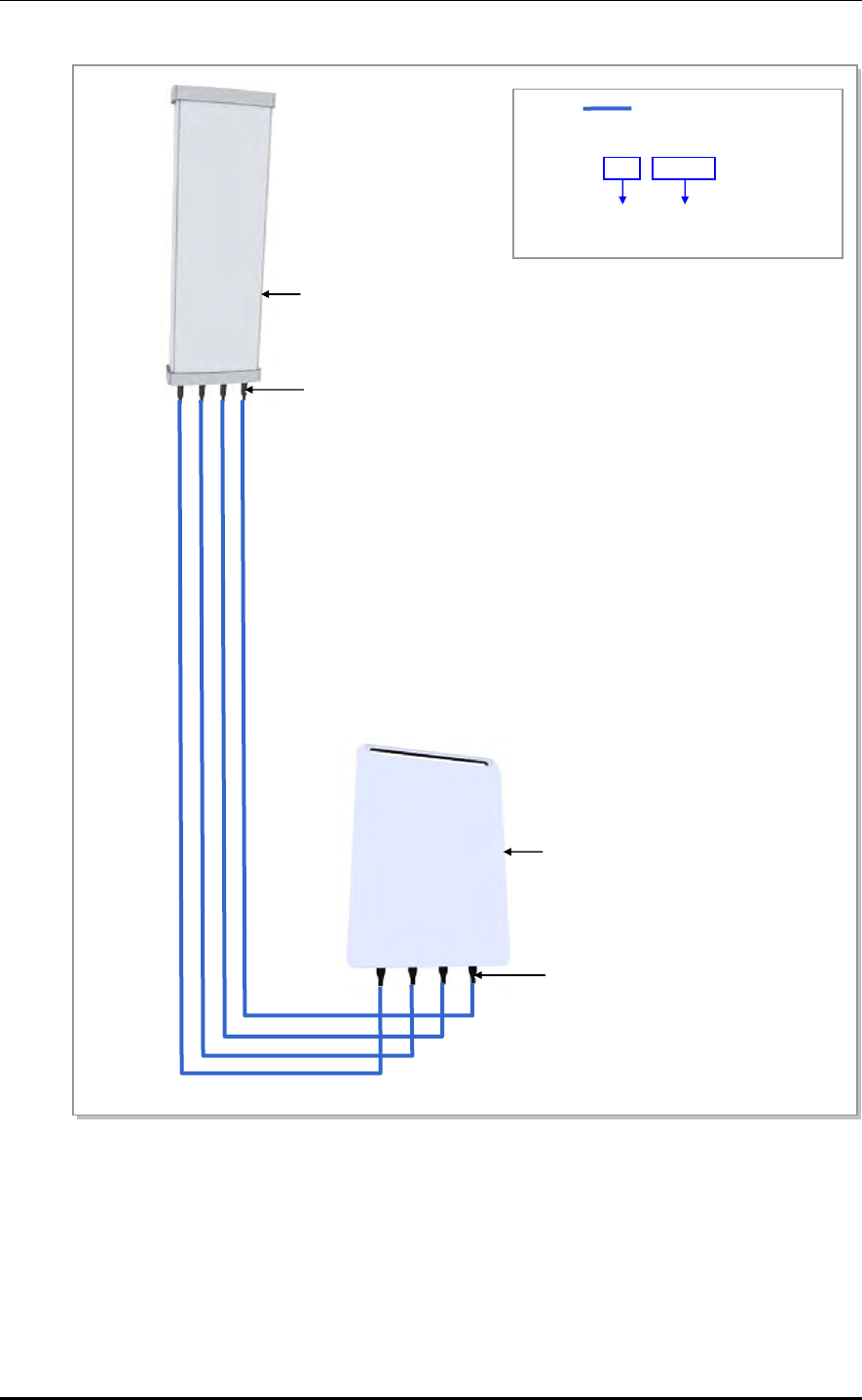
CHAPTER 3. Connecting Cables
3-26 © SAMSUNG Electronics Co., Ltd.
Figure 3.15 Heat Shrink Tube Specification
1/2 in. Feeder Line
※ Heat Shrink Tube (Jelly Type)
28/6 × 150 mm
Before Shrinking
/Max. Shrink
Length
Sector Antenna (4T4R)
N Type-Male Connector For 1/2 in. Feeder Line
- Heat Shrink Tube (Jelly Type, Black)
: 28/6 × 150 mm (1.10/0.24 × 5.91 in.)
RRH-2WB
Miniature Din Type-Male Connector
(For 1/2 in. Feeder Line)
- Heat Shrink Tube (Jelly Type, Black)
: 28/6 × 150 mm (1.10/0.24 × 5.91 in.)
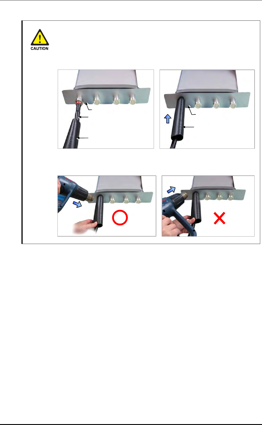
Mobile WiMAX/TD-LTE RRH-2WB Installation Manual/Ver.2.0
© SAMSUNG Electronics Co., Ltd. 3-27
Finishing Heat Shrink Tube of a Sector Antenna
1) Insert an antenna protection plate to antenna port.
2) Place the heat shrink tube on the connection point and shrink the heat shrink
tube using a heat gun.
Avoid aiming the heating gun toward the antenna’s body as shown in the
figure below.
Heat Shrink Tube (Jelly Type)
A
ntenna Jumper Cable
(1/2 in. Feeder Line) Heat Shrink Tube
(Jelly Type)
A
ntenna Protection Plate
A
ntenna Protection Plate
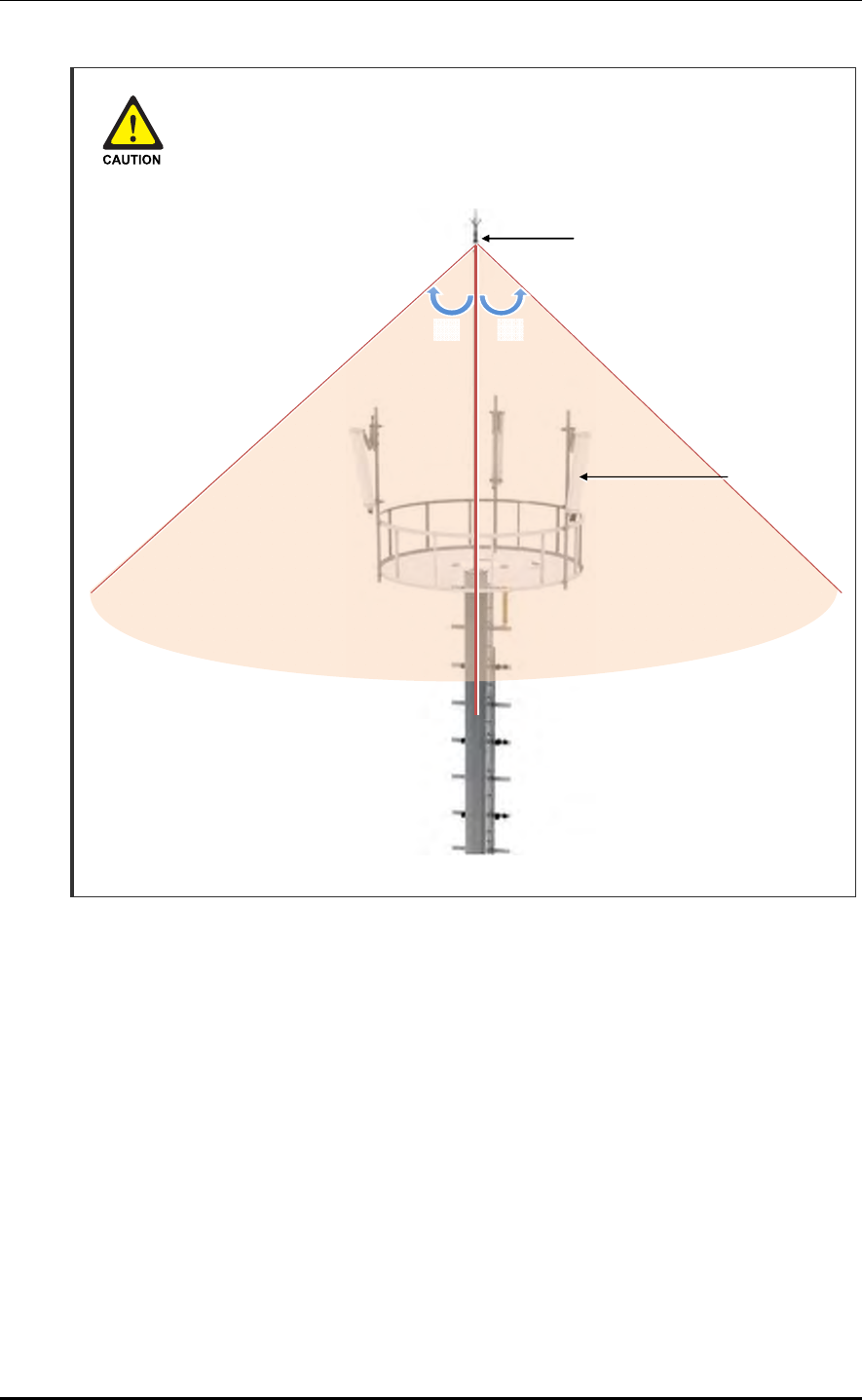
CHAPTER 3. Connecting Cables
3-28 © SAMSUNG Electronics Co., Ltd.
Installing the Antenna
When you install the antenna, the distant and angle between the antenna and
lightning rod must be within the protective angle (left/right side 45° each from the
central axis) to prevent the antenna from lightning damage.
Lightning Rod
45°45°
RF Antenna

Mobile WiMAX/TD-LTE RRH-2WB Installation Manual/Ver.2.0
© SAMSUNG Electronics Co., Ltd. 3-29
Checking Feeder Connection
After connecting the feeder cables, perform the continuity test and feeder cable return loss
to check if the feeder cable is changed and measure VSWR of antenna and feeder cable.
Measure all cables of section ~. The measured VSWR should be the specification
value or less. If the VSWR exceeds the specification value, disassemble the connector and
measure each section separately.
Checking VSWR for Minimum Cable Bend Radius and Length of RF Cable
If the VSWR value for minimum cable bend radius and length of RF cable is not
applied, system may not work properly because RF signals cannot transmit or
receive smoothly. So, the VSWR value for minimum cable bend radius and length
of RF cable must be checked and applied.
RF Cable Identification Tag Installation
Attach the identification tape in the below table to the RF cable.
Table 3.9 RF Cable Identification Tag
Category Description
Installation position Attach the identification tag to the both ends of the antenna.
Materials Use the material of aluminum coated by vinyl for the identification tag.
Fixing method - Antenna side: Attach the tag to the feeder line using binding strings
through the two holes on the tag.
- Equipment Side: Cover up the feeder line with the tag and fix it using
binding strings through the two holes on the tag.
Identification method The markings must be prevented from being erased by using relief
engraving or coated labels.
Connection Part of System External
Interface Connector Antenna

CHAPTER 3. Connecting Cables
3-30 © SAMSUNG Electronics Co., Ltd.
3.6 Installation Test
If the installation of the system is complete, progress the installation test to check the status
of the system. If there is any problem, restore the system and write out the failure table.
Table 3.10 Construction Situation Checklist
Category Check Items Criteria Result Remarks
Pass Fail
System
Installation
System fixing status
(vertical and horizontal)
Horizontal and vertical
locations
System arrangement status Horizontal and vertical
locations
Locking status and standard
compatibility of bolts/nuts/
washers
Visual inspection and
magnet test
External wiring and other
wirings
Visual inspection for
twist, array and
arrangement
Cable installation between
systems
Checking twist, distortion
and installation status
External connector
connection
Visual inspection to
check poor contact
(tightening status)
Other appurtenant work
(Cable duct installation and
others)
Visual inspection
Power
Acceptance
Equipment power line
standards
Visual inspection
Power terminal panel ↔
System
Visual inspection
Cabling Status Visual inspection for
twisted or entangled
status
Damage of cable sheath Visual inspection
Connection status of system
power connector
Visually inspect to ensure
that the power connector
is properly connected,
and that there are no
gaps or movement.
System input voltage
(BATT voltage)
Measurement by digital
meter (voltmeter)
Cabling status Visual inspection
(Flexible, Vinyl hose)
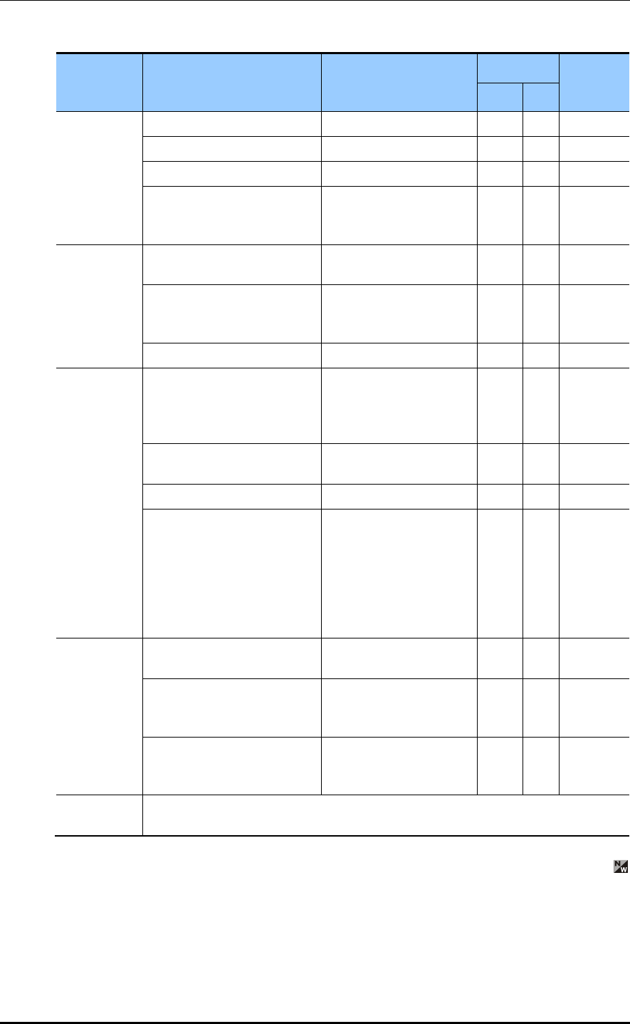
Mobile WiMAX/TD-LTE RRH-2WB Installation Manual/Ver.2.0
© SAMSUNG Electronics Co., Ltd. 3-31
Table 3.10 Construction Situation Checklist (Continued)
Category Check Items Criteria Result Remarks
Pass Fail
Ground
Construction
Ground line standard Visual inspection
Ground bar ↔ System Visual inspection
Ground line cabling status Cabling status check
Termination treatment of the
ground line (pressure
terminal)
Visual inspection
Feeder Line
Status
Feeder line cabling and
locking status
Beauty, robustness and
Bending
ANT installation and
attachment status
Visual inspection
(ANT bar’s vibration
status)
Connection and finish status Beauty and robustness
Various
TAG Status
Feeder tag Visual inspection
(Information mentioned:
length, loss value,
location)
Power cable tag Visual inspection
(Power Identification)
Ground table tag Visual inspection
Attachment status of the
label for the real-name
construction system
- Indoor: wall side of the gate
side
- Outdoor: inside of the
cover of the distribution box
Visual inspection
(size and material)
Finish
Status
Cable duct bolt’s attachment
status
Visual inspection
Feeder inlet finish treatment
status
Visual inspection (check
if the rear part is
attached)
Status of inside/outside of
the system and vicinity of the
base station
Visual inspection
General
Opinion

CHAPTER 3. Connecting Cables
3-32 © SAMSUNG Electronics Co., Ltd.
This page is intentionally left blank.

Mobile WiMAX/TD-LTE RRH-2WB Installation Manual
© SAMSUNG Electronics Co., Ltd. A-1
ANNEX A. Sector Antenna Installation
A.1 Cautions when Installing a Sector Antenna
Precautions of antenna installation are as follows.
Sector antennas should be installed vertically. (± 1°)
Antenna is the precise material, so be careful not to make damage or form change.
When moving antenna, use the tool suitable to rating. In addition, use the rated
carrying device which is at least 200 % or more than antenna considering the stability.
Be careful not to give too much strength to the antenna.
If it rains, suspend connecting the feeder cable and antenna.
Fix it after adjusting the direction of antenna exactly.
Distance between steel tower and antenna and the distance between send-receive
antennas are based on the antenna layout.
Attach the antenna on the position specified in the drawing.
Install the antenna not to make a feature change of the antenna considering the
direction of the radiation
Connect the antenna not making the alien substance flowed so that Passive Inter-
Modulation Distortion (PMID) is not affected.
Measure VSWR of all antennas and the value should be within the regulated value.
A.2 Sector Antenna Layout
The method of sector antenna layout is as follows.
1) Use the transit to adjust the antenna installation direction exactly.
2) Fix the direction of the sector antenna, same as the angle settled when designing the
cell after installing the steel tower.
3) Arrange the antennas of each sector to the sector directional angle at right angles by
adjusting the distance between antenna and steel tower.
In the event of the station whose the direction between sectors is not 120°, install it to
make the steel tower and antenna direction different being careful of the tilt and azimuth.
4) For circular platform, separate the antenna interval at maximum.
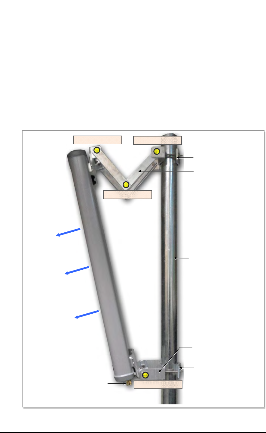
ANNEX A. Sector Antenna Installation
A-2 © SAMSUNG Electronics Co., Ltd.
A.3 Sector Antenna Installation
The method of sector antenna installation is as follows.
1) Put up an antenna pole and insert the sector antenna into the antenna pole using a
fixing clamp.
2) Set the antenna’s up/down tilt to 0° and fix the fixing clamps at the top and bottom.
3) After tightening the fixing clamp, adjust the antenna up/down (tilt) depending on the
signal strength. The bolt of the guide clamp must be loosened, so the antenna angle can
be adjusted.
4) After setting the antenna angle, tighten the bolt of the guide clamp, which was
loosened previously. Regarding the nut, the double nut mounting should be used to
prevent the nut from coming loose.
Figure A.1 Sector Antenna
Antenna Input Port
Pole
Main Radiation Direction
Upper Fixing Clamp
Lower Fixing Clamp
Upper Guide Clamp
Lower Guide Clamp
Guide Clamp Bolt_2
Guide Clamp Bolt_1
Guide Clamp Bolt_3
Guide Clamp Bolt_4

Mobile WiMAX/TD-LTE RRH-2WB Installation Manual/Ver.2.0
© SAMSUNG Electronics Co., Ltd. A-3
Installing the Antenna
When you install the antenna, the antenna must be installed within the protective
angle (left/right side 45° each from the central axis) of lightning rod to prevent the
antenna from lightning damage.
Lightning Rod
GPS Antenna
45°45°
RF Antenna

ANNEX A. Sector Antenna Installation
A-4 © SAMSUNG Electronics Co., Ltd.
This page is intentionally left blank.
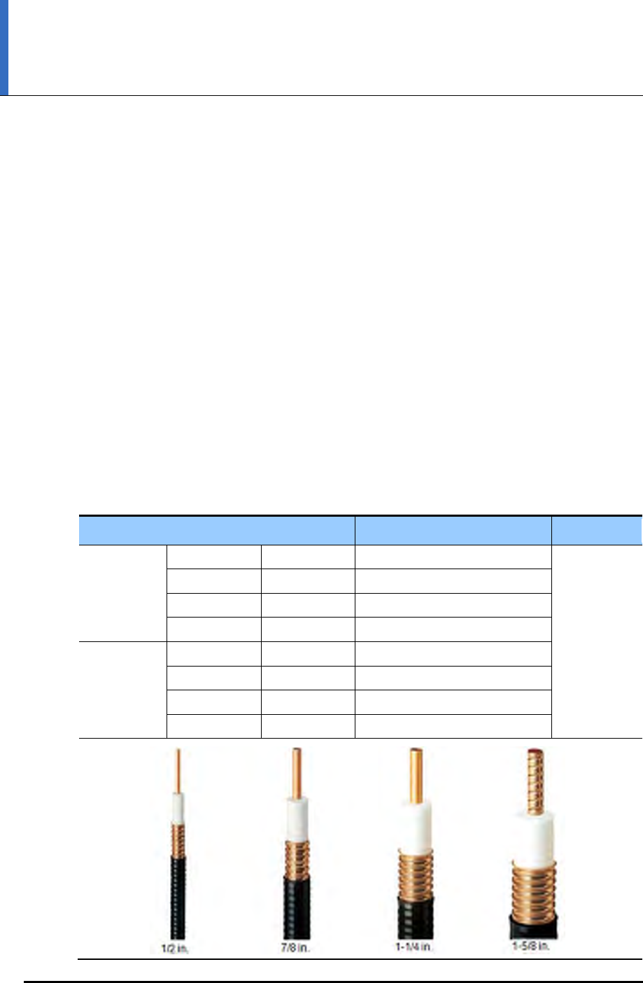
Mobile WiMAX/TD-LTE RRH-2WB Installation Manual
© SAMSUNG Electronics Co., Ltd. B-1
ANNEX B. Installing Feeder Cable
B.1 Cautions When Installing Feeder Cable
When installing the feeder, the following cautions shall be considered:
Put a plate to work not to make damage for the surface of the feeder cable.
If there is external damage of the feeder cable, cut the damaged part and work wiring.
After connecting the antenna to the feeder cable, finish the connection part of the
contracted pipe using the contracted tube.
Attach the cognitive tapes to the both ends of the feeder cable, which makes it easy to
recognize.
When connecting cabinet, antenna and lightening arrestor, etc. to the feeder cable,
connect strongly to prevent from generating reflected wave.
The curvature radius should be maximized, keep the minimum curvature radius.
Table B.1 Curvature Radius of Feeder Cable for Outdoor
Specification Allowed Radius of Curvature Remark
LS Feeder
Line
HFC-12D 1/2 in. 125 mm (4.92 in.) Outdoor
HFC-22D 7/8 in. 250 mm (9.84 in.)
HFC-33D 1-1/4 in. 380 mm (14.96 in.)
HFC-42D 1-5/8 in. 510 mm (20.08 in.)
RFS Feeder
Line
LCF12-50 1/2 in. 125 mm (4.92 in.)
LCF78-50 7/8 in. 250 mm (9.84 in.)
LCFS114-50 1-1/4 in. 380 mm (14.96 in.)
LCF158-50 1-5/8 in. 500 mm (19.69 in.)
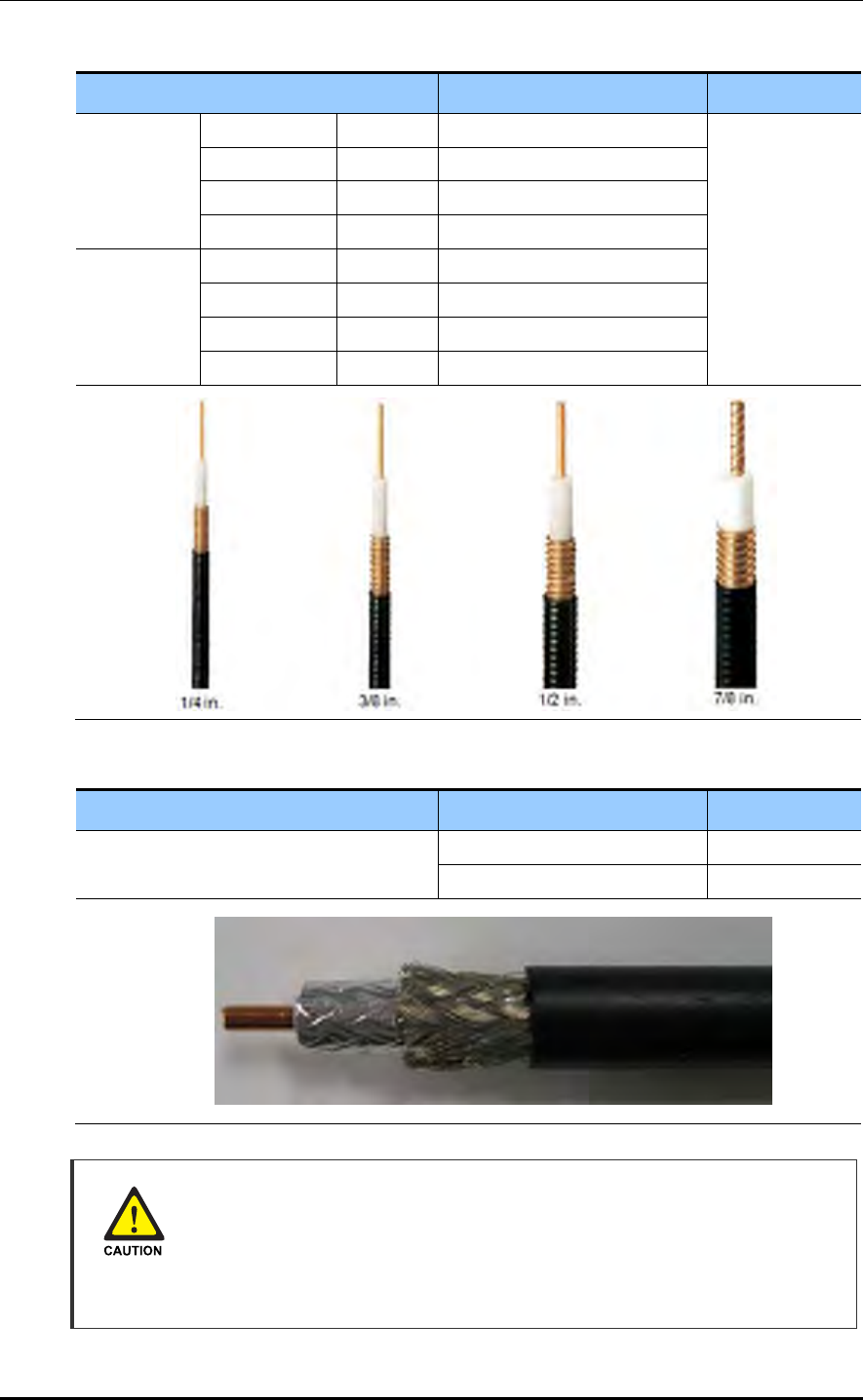
ANNEX B. Installing Feeder Cable
B-2 © SAMSUNG Electronics Co., Ltd.
Table B.2 Curvature Radius of Feeder Cable for Indoor (Based on LS Feeder Line)
Specification Allowed Radius of Curvature Remark
LS Feeder
Line
HFSC 6D 1/4 in. 25 mm (0.98 in.) Indoor
HFSC 10D 3/8 in. 25 mm (0.98 in.)
HFSC 12D 1/2 in. 32 mm (1.26 in.)
HFSC 22D 7/8 in. 125 mm (4.92 in.)
RFS Feeder
Line
SCF14-50 1/4 in. 25 mm (0.98 in.)
SCF38-50 3/8 in. 25 mm (0.98 in.)
SCF12-50 1/2 in. 32 mm (1.26 in.)
UCF78-50 7/8 in. 125 mm (4.92 in.)
Table B.3 Curvature Radius of LMR-400 (Based on Times Microwave System)
Specification Allowed Radius of Curvature Remark
LMR-400 25.4 mm (1 in.) Installation
101.6 mm (4 in.) Repeated
Radius of Curvature of Feeder Line
When installing a feeder line, the radius of curvature of the sections where cables
bent should be larger than the allowed radius of curvature. If the radius of
curvature for the feeder line installation is less than the allowed radius of
curvature, it may affect the performance of the system.
Mobile WiMAX/TD-LTE RRH-2WB Installation Manual/Ver.2.0
© SAMSUNG Electronics Co., Ltd. B-3
Ensure that the feeder cable does not interfere with steel towers, ladders and in the
areas chiefly used by people.
Connect the connector to the antenna in a straight line and after connecting, do not
apply excessive force.
Use the vinyl tape for electricity and heat shrink tube for the external exposed part of
the connector not to avoid leak water.
Wind the self-bonding rubber tape overlapping (keep a distance as the half size of
rubber tape) to the connector connection part and wind the vinyl tape for electricity to
the 2 times or more and then cover with the jelly type heat shrink tube.
Connection of Feeder Cable Connector
Connecting the feeder cable connector is critical process, so the qualified workers
who finished the related education should perform.
Table B.4 Connector Connection Torque Value
Connector Torque Value
SMA connector 2.5 kgf·cm (0.18 lbf·ft)
TNC connector 9 kgf·cm (0.65 lbf·ft)
N-type connector 20 kgf·cm (1.45 lbf·ft)
Din-type connector 200 kgf·cm (14.46 lbf·ft)
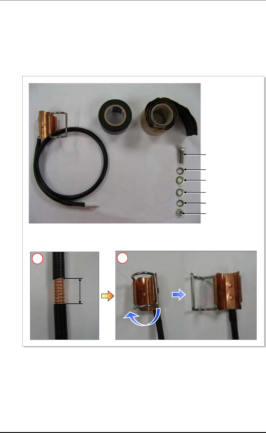
ANNEX B. Installing Feeder Cable
B-4 © SAMSUNG Electronics Co., Ltd.
B.2 Antenna Feeder Cable Ground
Ground the antenna feeder line using the grounding kit located under the Tower Ground
Bar (TGB) installed in the lower section of the tower or in the antenna feeder line duct.
The procedure for connecting the ground kit to the feeder line is as follows:
Figure B.1 Feeder Cable Grounding (1)
55 mm
M6 Hex. Nut
Ground Kit
Insulation Tape Rubber Tape
M6 × 25L Hex. Bolt
M6 Spring Washer
M6 Plane Washer
M6 Plane Washer
M6 Spring Washer
1) Remove about 55 mm (2.17 in.) of the sheath of cable when the 7/8 in. feeder cable is used.
2) Open it by returning hook of the clamp fixing for Ground kit in the left direction.
1 2
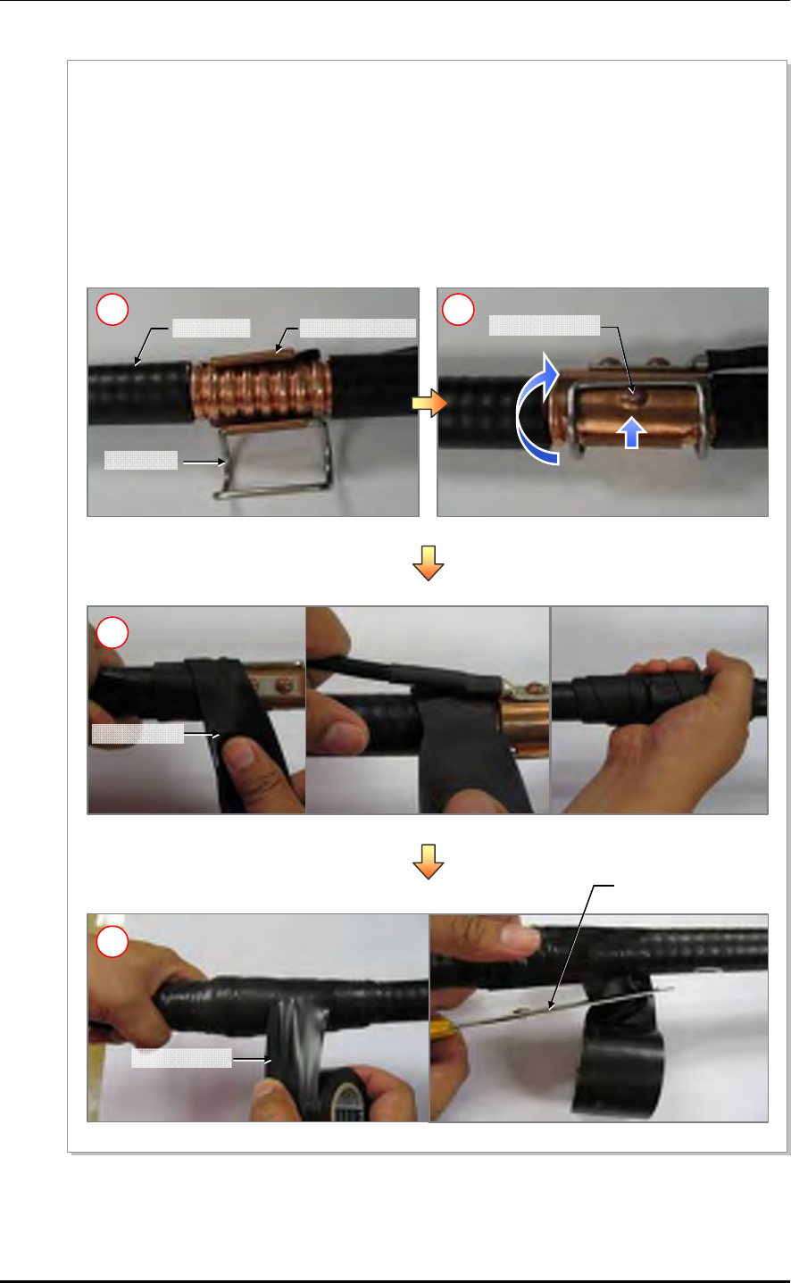
Mobile WiMAX/TD-LTE RRH-2WB Installation Manual/Ver.2.0
© SAMSUNG Electronics Co., Ltd. B-5
Figure B.2 Feeder Cable Grounding (2)
Protrusion area
Clam
p
lock
Feeder Line Ground Kit Clam
p
Scissors (knife)
Rubber Ta
p
e
Insulation Ta
p
e
3) Insert the ground kit clamp into the place from which the feeder line sheath is removed.
4) Pull the clamp lock to the upward so that the lock can be hung on the global protrusion area on the side.
5) Overlap the exposed part of the ground kit clamp using rubber tape (Keep a distance as the half size of
rubber tape) and press it with your hands lightly to make rubber tape adhere well.
6) Wrap the part where the rubber tape is attached using insulation tape two times or more. When cutting
off the tape, cut it off neatly using a cutting device such as scissors or a knife.
4
5
6
3
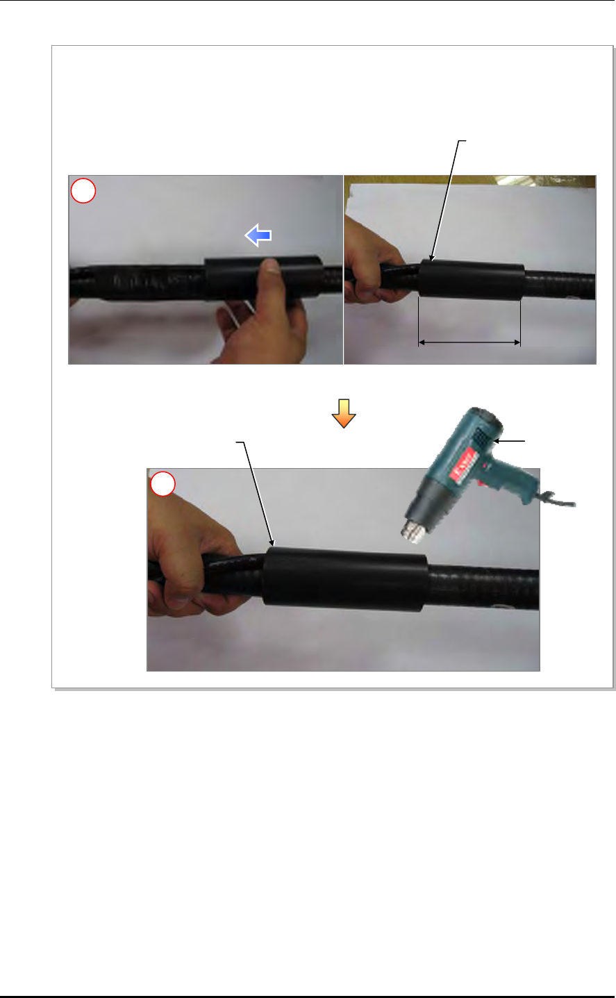
ANNEX B. Installing Feeder Cable
B-6 © SAMSUNG Electronics Co., Ltd.
Figure B.3 Feeder Cable Grounding (3)
200 mm
(7.87 in.)
Heating Gun
Heat Shrink Tube
42 mm (1.65 in.)
Heat Shrink Tube
42 mm (1.65 in.)
7) Align the 42 mm (1.65 in.) heat shrink tube [jelly type, 200 mm (7.87 in.)] inserted when installing the
feeder line into the fixing part of the ground kit.
8) Shrink the heat shrink tube[jelly type, 200 mm (7.87 in.)] by heating gun.
7
8
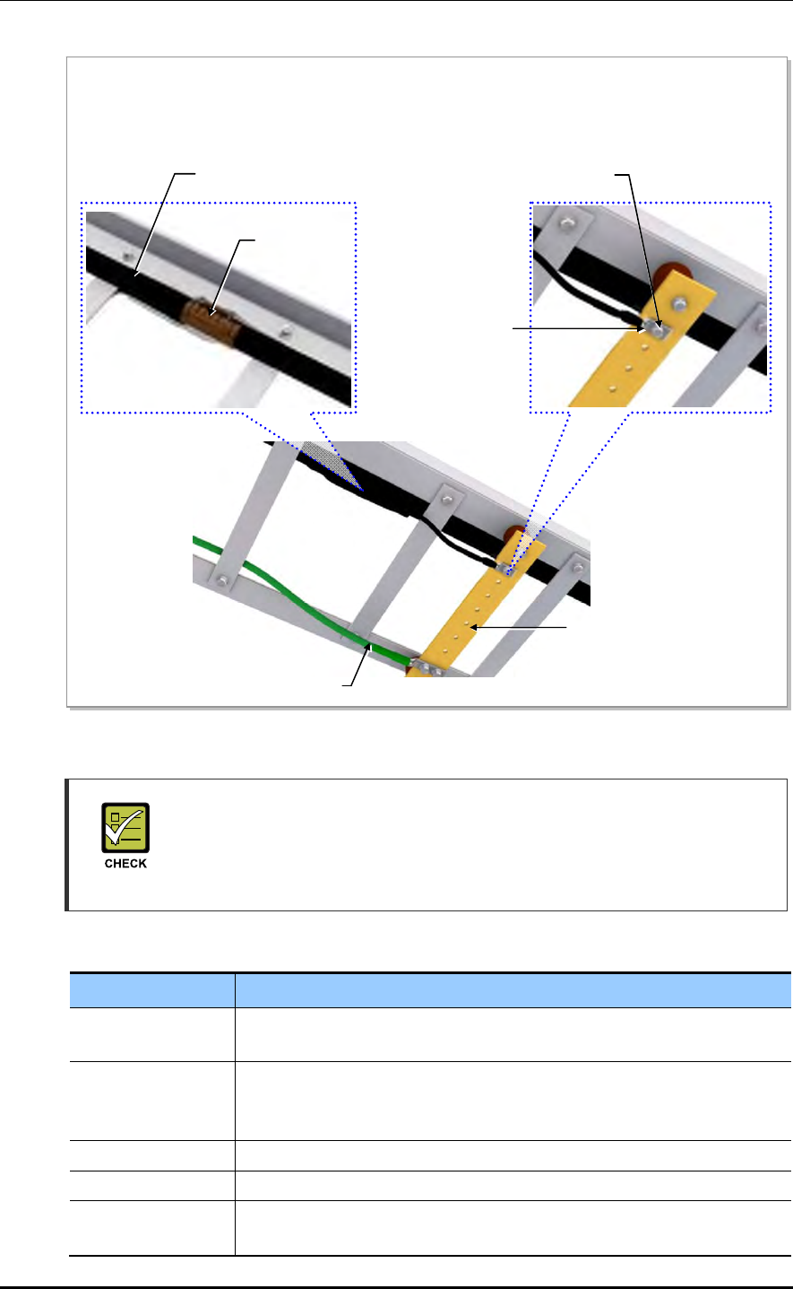
Mobile WiMAX/TD-LTE RRH-2WB Installation Manual/Ver.2.0
© SAMSUNG Electronics Co., Ltd. B-7
Figure B.4 Feeder Cable Grounding (4)
Checking the Ground Kit and TGB Specifications
The specifications, clamp, and pressure terminal type of the ground kit and TGB
differ depending on manufacturers. Make sure to check the specifications of the
ground kit and TGB, and identify the installation method before installing it.
Table B.5 TGB Installation Example
Category Description
TGB Usage Earth terminal board for feeder cable for grounding in using the feeder
cable of more than 7/8 in.
TGB Location Lower section of cable rack in feeder cable duck
- Less than 20 m (65.62 ft): 1 (Ex. steel tower lower section)
- Exceed 20 m (65.62 ft): 2 or more (Ex. steel tower lower and upper section)
Material Pure copper
Installation Method Using the insulator to separate from the steel tower electrically
Connection Method Extract the AWG1, GV 35 mm2 ground cable to the direction of the floor and
weld it to the tower’s ground cable.
9) After the ground kit has been installed to the feeder line, attach the pressure terminal (1 hole) of the
ground cable connected to the ground kit to the TGB.
10) When attaching the pressure terminal, use M6 × 25L hex. Bolts.
TGB (Tower Ground Bar)
TGB Ground Cable
(AWG 1, GV 35 mm2 × 1C)
M6 × 25L Hex. Bolt (STS304)
Pressure Terminal
(1 Hole)
Ground kit
7/8 in. Feeder Line

ANNEX B. Installing Feeder Cable
B-8 © SAMSUNG Electronics Co., Ltd.
B.3 Tower Ground Construction
1) Install a Tower Ground Bar (TGB) that will be used to ground a feeder cable onto the
tower. If the height of the tower is exceeds 20 m (65.62 ft), two or more TGBs should
be installed (onto the lower and upper sections of the tower). If the tower is 20 m
(65.62 ft) or less, one TGB should be installed. Since the TGB installation location and
the number of TGBs to be installed can differ depending on the system environment
and provider’s standards, consult your service provider.
2) Each TGB should be grounded and separated from other grounds. If there is an
existing ground bar or ground cable for TGB, install the TGB by branching from it
using a ground cable (AWG 1, GV 35 mm2 × 1C) ground cable. (However, the
specification of TGB ground cable can be different, defending on the standard of
service provider.)
3) Tighten the ground kit (feeder cable grounding assembly) to the TGB ground terminal
and the tower hole using the pressure terminal hole attached at the end of the ground
kit’s ground cable.
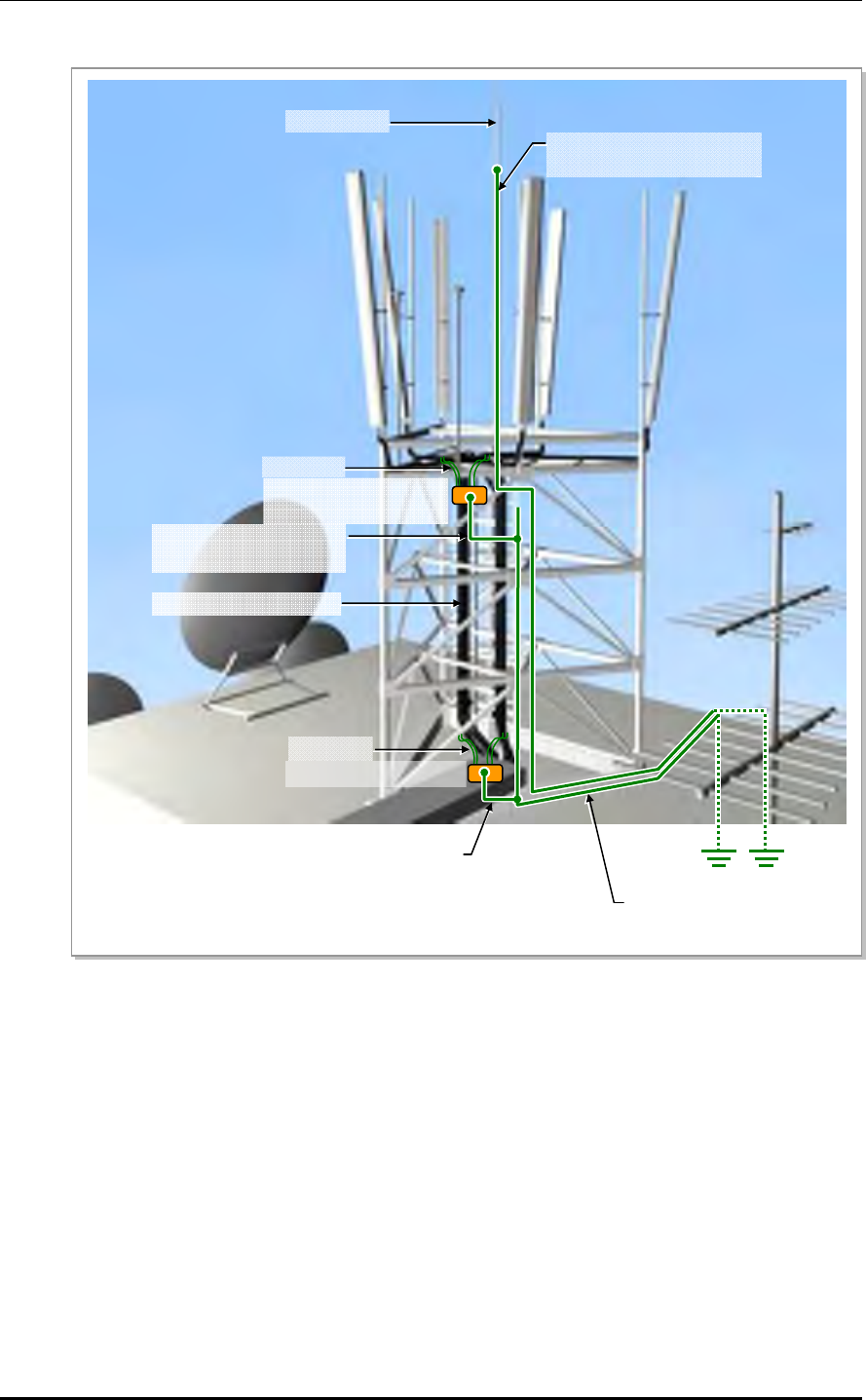
Mobile WiMAX/TD-LTE RRH-2WB Installation Manual/Ver.2.0
© SAMSUNG Electronics Co., Ltd. B-9
Figure B.5 Connecting the Tower Ground Cable
Lightning Rod
7/8 in. Feeder Line or more
Ground Kit
TGB (Tower Ground Bar)
(Tower Height>20 m)
TGB Ground Cable
(AWG1, GV 35 mm2 × 1C)
Lightning Rod Ground Cable
(AWG4/0, GV 95 mm2 × 1C)
TGB (Tower Ground Bar)
Ground Kit
TGB Ground Cable
(AWG1, GV 35 mm2 × 1C)
TGB Ground Cable
(AWG4/0, GV 95 mm2 × 1C)

ANNEX B. Installing Feeder Cable
B-10 © SAMSUNG Electronics Co., Ltd.
This page is intentionally left blank.

Mobile WiMAX/TD-LTE RRH-2WB Installation Manual
© SAMSUNG Electronics Co., Ltd. C-1
ANNEX C. Connector Assembly
C.1 N type-male (1/2 in. feeder line)
Below is the method for assembling the N type-male connector to the 1/2 in. feeder line.
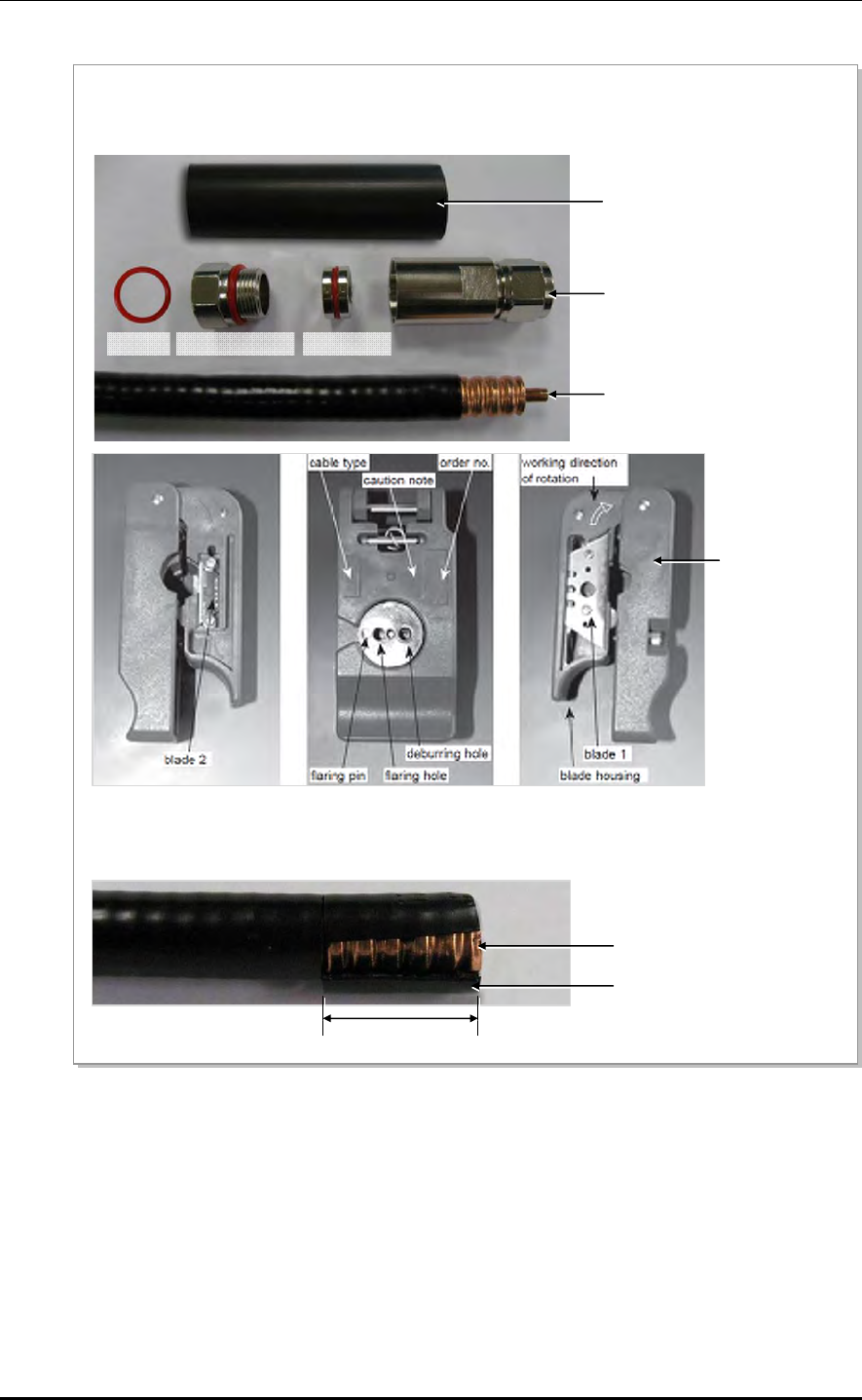
ANNEX C. Connector Assembly
C-2 © SAMSUNG Electronics Co., Ltd.
Figure C.1 Assembling the N type-male (1/2 in. Feeder Line) Connector (1)
1) The components of the N type-male are an N type-male body, an insert ring, a clamping nut, O-ring, and a heat
shrink tube, and it is assembled using the wire stripper, trimming tool, spanner, etc.
2) Using a stripping tool or a knife, strip the 1/2 in. feeder line by 25 mm (0.98 in.) from the end, as shown in the
figure below.
Trimming Tool
Heat Shrink Tube [28 mm (1.1 in.)]
Insert Ring
N type-Male Body
Clamping Nut
1/2 in. Feeder Line
O-Ring
25 mm
1/2 in. Feeder Line Conductor
1/2 in. Feeder Line Jacket
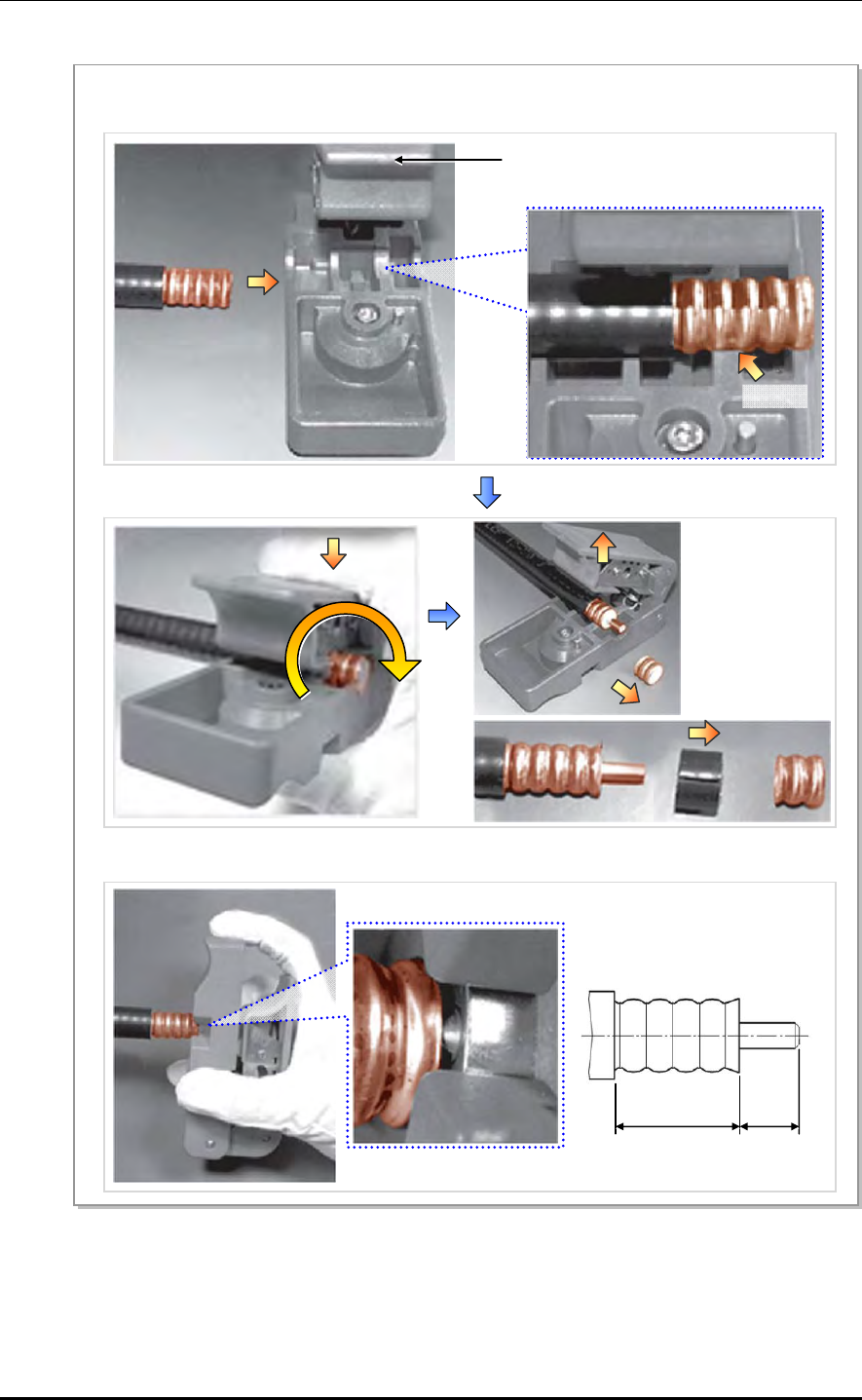
Mobile WiMAX/TD-LTE RRH-2WB Installation Manual/Ver.2.0
© SAMSUNG Electronics Co., Ltd. C-3
Figure C.2 Assembling the N type-male (1/2 in. Feeder Line) Connector (2)
Trimming Tool
3) Remove the 11 mm (0.43 in.) of the external conductor end and 10 mm (0.39 in.)of the jacket using a
trimming tool.
Collet
4) Insert the internal conductor into the deburring hole at the bottom of the trimming tool to trim it.
24 mm
(0.94 in.)
11 mm
(0.43 in.)
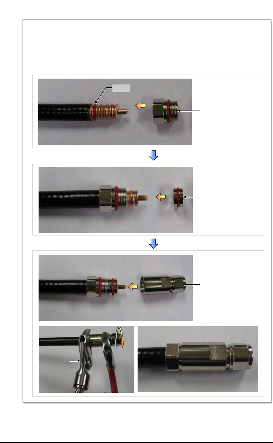
ANNEX C. Connector Assembly
C-4 © SAMSUNG Electronics Co., Ltd.
Figure C.3 Assembling the N type-male (1/2 in. Feeder Line) Connector (3)
5) Insert the o-ring, clamping nut, insert ring and N type-male body to the stripped 1/2 in. feeder line in
this order. O-ring is inserted into the second groove from inside of outer insulator.
6) Tighten the clamping nut and N type-male body inserted into the 1/2 in. feeder line firmly using a spanner.
The recommended torque for tightening the clamping nut and N type-male body is 30~50 N.m (306~510
lbf·ft). (Note that it should only be tightened by rotating the external body with the clamping nut in a fixed
and stable position.)
Insert Ring
N type-Male Body
Clamping Nut
O-Ring
Keep the
fixed state
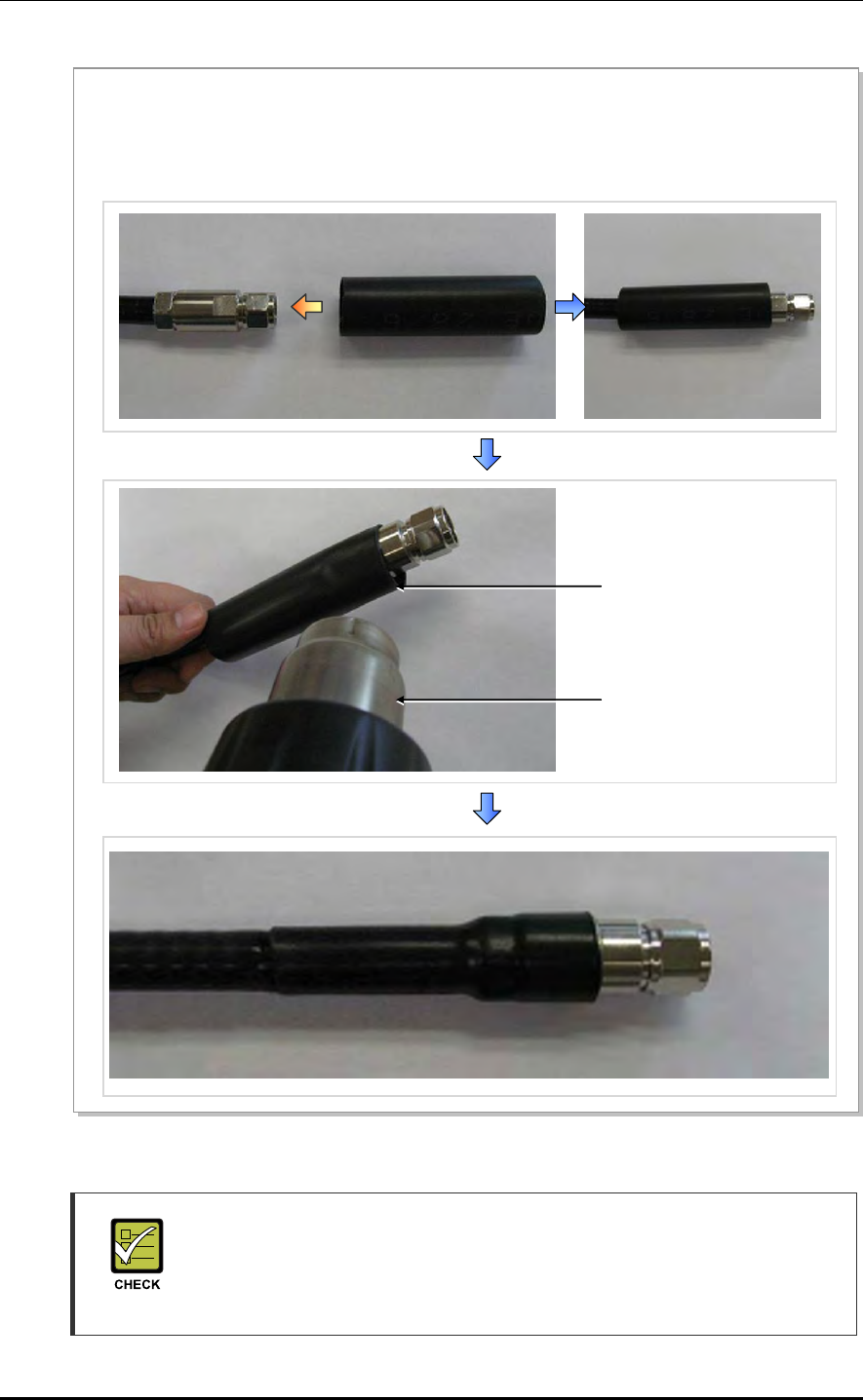
Mobile WiMAX/TD-LTE RRH-2WB Installation Manual/Ver.2.0
© SAMSUNG Electronics Co., Ltd. C-5
Figure C.4 Assembling the N type-male (1/2 in. Feeder Line) Connector (4)
Checking to carry out when assembling the N type-male connector
The shape, tool and assembly method may differ depending on the connector
type and manufacturer. Make sure to check the user manual provided by the
manufacturer before assembling.
Clamping Nut
7) Insert the heat shrink tube into the 1/2 in. feeder line fitted with the N type-male connector as shown in the
figure below.
- Heat shrink tube: Ф 28 mm, 100 mm (Ф 1.1 in., 3.94 in.)
8) Shrink the heat shrink tube inserted into the 1/2 in. feeder line using a heating gun.
Heating Gun
Heat Shrink Tube
28 mm (1.1 in.)
ANNEX C. Connector Assembly
C-6 © SAMSUNG Electronics Co., Ltd.
C.2 Din type-male (1/2 in. Feeder Line)
Below is the method for assembling the Din type-male connector to the 1/2 in. feeder line.
Figure C.5 Assembling the Din type-male (1/2 in. Feeder Line) Connector (1)
2) Straighten the cable, then, using a suitable tool, strip it to the connector’s wire strip length.
When cutting the sheath, hold the cable firmly with one hand and cut the cable pulling the cutting
tool inwards with the other hand. Gently rotate the tool several times (do not pull it too hard), so that
the internal copper line is not damaged.
3) Using a cutter, cut the sheath from the stripped edge to the end of the cable and completely strip the sheath.
Cutting Tool
Cutter
Feeder Line
1) The components of the Din type-male are an Din type-male body, pin, an insert ring, a clamping nut,
o-ring, and a heat shrink tube, and it is assembled using the wire stripper, trimming tool, wrench, etc.
4) Insert the o-ring, clamping nut, insert ring, pin and Din type-male body into the stripped feeder line in
this order.
Din type-male Body
Pin
Insert Ring
Clamping Nut
O-Ring
Feeder Line
Heat Shrink Tube
Mobile WiMAX/TD-LTE RRH-2WB Installation Manual/Ver.2.0
© SAMSUNG Electronics Co., Ltd. C-7
Figure C.6 Assembling the Din type-male (1/2 in. Feeder Line) Connector (2)
Checking to carry out when assembling the Din type-male connector
The shape, tool and assembly method may differ depending on the connector
type and manufacturer. Make sure to check the user manual provided by the
manufacturer before assembling.
Spanner (keep the fixed state)
5) Tighten firmly the clamping nut and Din type-male body inserted to the 1/2 in. feeder line using a wrench.
The recommended torque for tightening the clamping nut and Din type-male body is 30~50 N.m
(306~510 lbf·ft) (Note that it should only be tightened by rotating the external body with the clamping nut
in a fixed and stable position.)
Clamping Nut
6) Insert the heat shrink tube [28 mm/10 cm (1.10 in./3.94 in.)] to the 1/2 in. feeder line fitted with the Din
type-male connector; and shrink the heat shrink tube inserted into the feeder line using a heating gun.
Heating Gun
Heat Shrink Tube
Din type-Male Body
ANNEX C. Connector Assembly
C-8 © SAMSUNG Electronics Co., Ltd.
C.3 Finishing the Connector Connection Part by
Tape
Finishing the connector connection part by tape (insulation tape, rubber tape, etc.) in the
outdoor environment is as follows:
Figure C.7 Finishing the Connector Connection Part by Tape
Cable Tie
Rubber Tape
Insulation Tape
1) Overlap the exposed part of the connector connection part using rubber tape (Keep a distance as the
half size of rubber tape) and press it with your hands lightly to make rubber tape adhere well.
2) Wrap the part where the rubber tape is attached using insulation tape two times or more. When cutting
off the tape, cut it off neatly using a cutting device such as scissors or a knife.
3) Bind the end part of the insulation tape using cable tie to prevent slips.
Mobile WiMAX/TD-LTE RRH-2WB Installation Manual/Ver.2.0
© SAMSUNG Electronics Co., Ltd. C-9
C.4 How to Shrink the Heat Shrink Tube
C.4.1 When Assembling a Connector to the Feeder Line
Below is the procedure for shrinking the heat shrink tube.
Figure C.8 Shrinking the Heat Shrink Tube_Feeder Line (1)
1) Prepare a 1/2 in. feeder line, heat shrink tube, and
heating gun to finish the cable using a heat shrink
tube.
2) Insert the heat shrink tube into the 1/2 in. feeder
line, and then place the heat shrink tube at the end
of the cutting area of the connector where the tool
will be used.
3) Set the heating gun to 250 to 300°C. (482~572°F)
Heat Shrink Tube (Jelly Type)
28/6 × 150 mm (5.9 in.)
1/2 in. Connector
Heating Gun
1/2 in. Feeder Line
Cutting Area
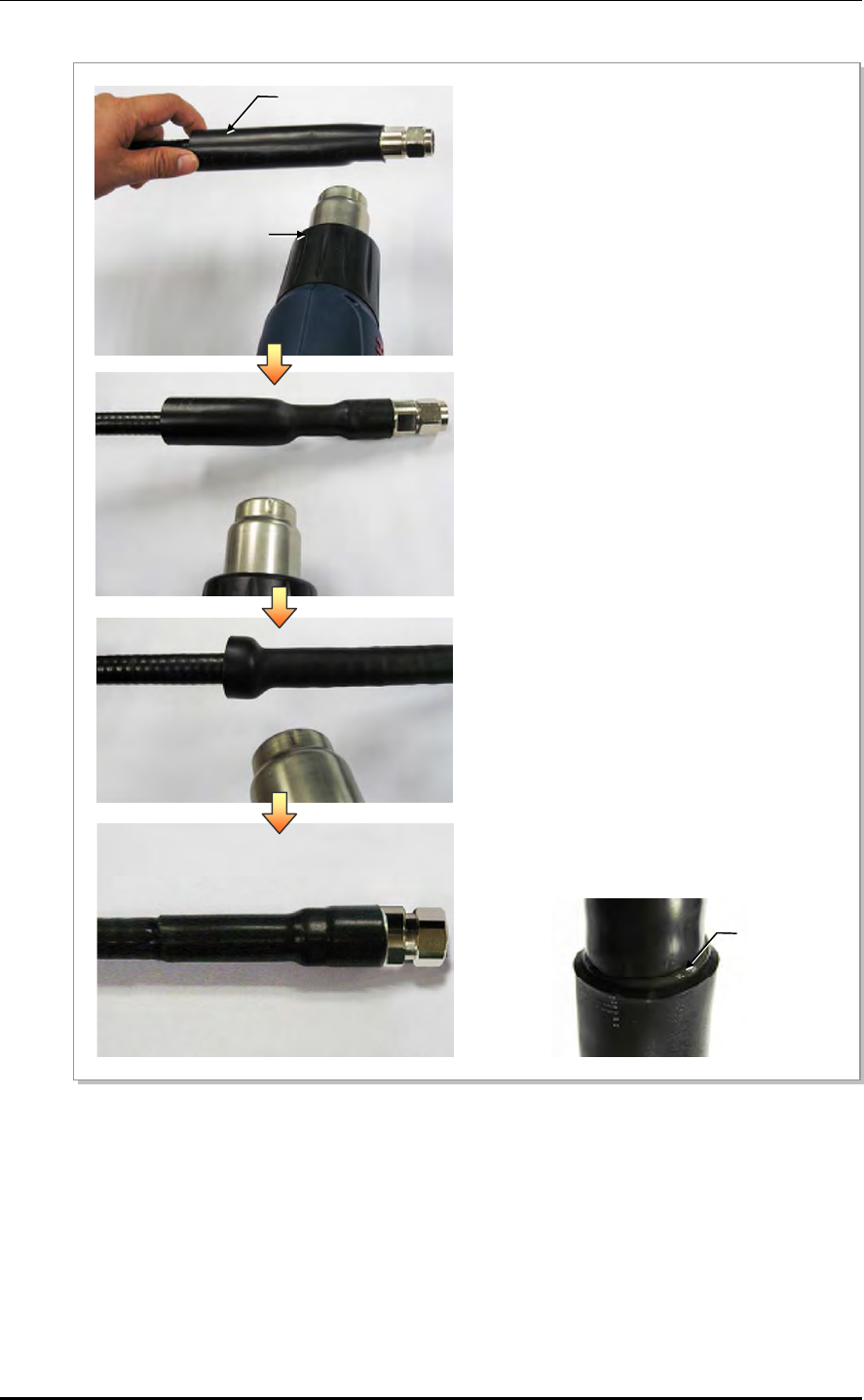
ANNEX C. Connector Assembly
C-10 © SAMSUNG Electronics Co., Ltd.
Figure C.9 Shrinking the Heat Shrink Tube_Feeder Line (2)
6) Shrink the heat shrink tube until jelly appears at the
end part of it (refer the Figure below) and finish it.
4) Holding one end of the heat shrink tube with your
hand, apply heat starting from the connector using
the heating gun.
5) Rotate the heating gun so that heat is evenly
distributed to prevent that bubbles are generated or
heat is concentrated to a specific part.
Heat Shrink Tube
Heating Gun
Jelly

Mobile WiMAX/TD-LTE RRH-2WB Installation Manual/Ver.2.0
© SAMSUNG Electronics Co., Ltd. C-11
C.4.2 When Connecting a Connector to another Connector
Below is the procedure for shrinking the heat shrink tube.
Figure C.10 Shrinking the Heat Shrink Tube_Connection between Connectors (1)
1) Prepare a 1/2 in. feeder line, 7/8 in. feeder line,
heat shrink tube, and heating gun to finish the
cable using a heat shrink tube.
3) Insert the heat shrink tube, placing connector part
(where 1/2 in. and 7/8 in. feeder line will be connected)
in the center, and mark the center part.
Heat Shrink Tube (Jelly Type)
38/12 × 300 mm (11.81 in.)
7/8 in. Feeder Line
Connector
1/2 in. Feeder Line
Heating Gun
2) Inset the heat shrink tube to one end of the feeder
line and connect the connector.
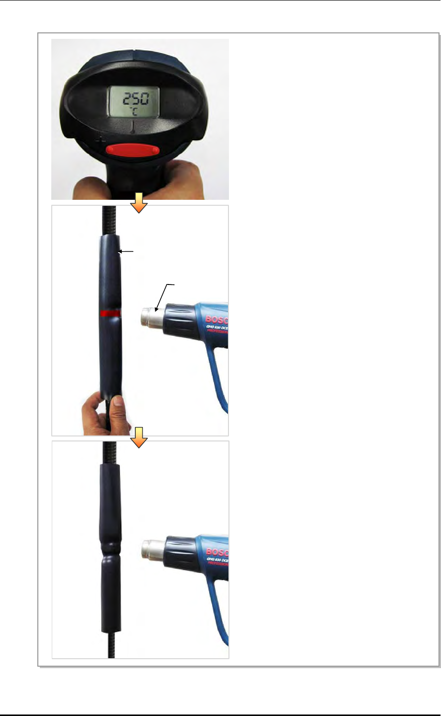
ANNEX C. Connector Assembly
C-12 © SAMSUNG Electronics Co., Ltd.
Figure C.11 Shrinking the Heat Shrink Tube_Connection between Connectors (2)
4) Set the heating gun to 250 to 300°C. (482~572°F)
5) Holding one end of the heat shrink tube with your
hand, apply heat starting from the marked part at
the center using the heating gun.
6) Rotate the heating gun so that heat is evenly
distributed to prevent that bubbles are generated
or heat is concentrated to a specific part.
Heat Shrink Tube
Heating Gun
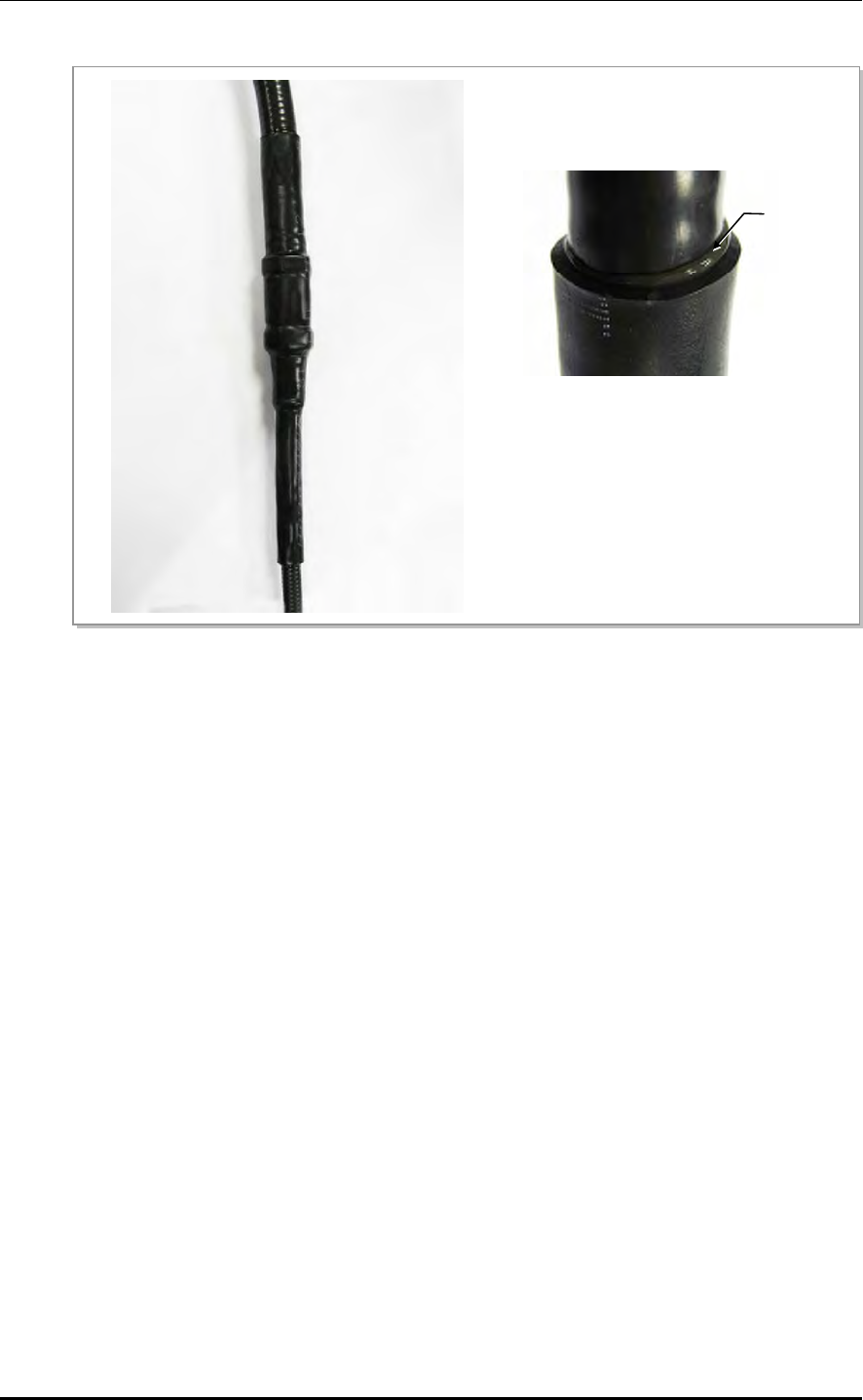
Mobile WiMAX/TD-LTE RRH-2WB Installation Manual/Ver.2.0
© SAMSUNG Electronics Co., Ltd. C-13
Figure C.12 Shrinking the Heat Shrink Tube_Connection between Connectors (3)
7) Shrink the heat shrink tube until jelly appears at
the end part of it (refer the figure below) and
finish it.
Jelly
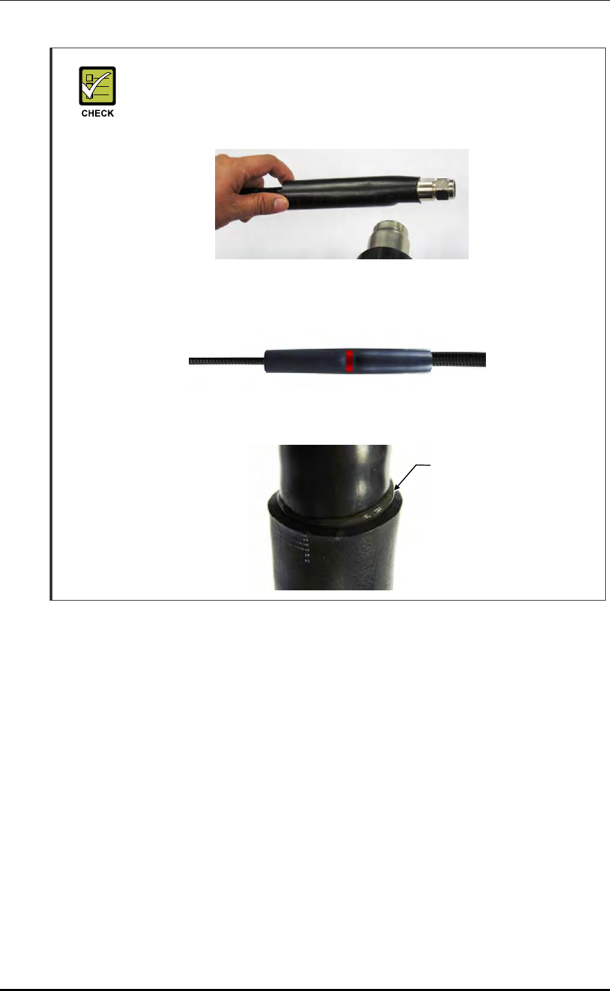
ANNEX C. Connector Assembly
C-14 © SAMSUNG Electronics Co., Ltd.
Check for Working with the Heat Shrink Tube
- If you work without holding one end of the heat shrink tube, the location of the
heat shrink tube may be changed. Therefore, make sure to hold one end of it
when applying heat.
- The connector part where 1/2 in. and 7/8 in. feeder line are connected must be
the center of the heat shrink tube. After inserting the heat shrink tube, mark the
center part.
- If jelly does not appear on the end of the heat shrink tube, it may mean that it is
not shrunk properly. Apply heat until jelly appears using a heating gun.
Jelly
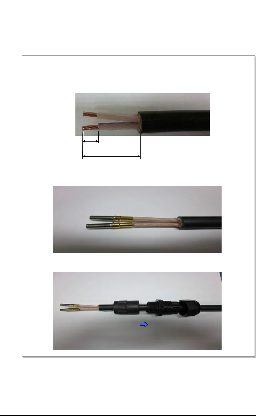
Mobile WiMAX/TD-LTE RRH-2WB Installation Manual/Ver.2.0
© SAMSUNG Electronics Co., Ltd. C-15
C.5 Power Connector Assembly
The procedure for assembling the power connector (Amphenol, CJE-AL06M25U15-2S) is
as follows.
Figure C.13 Power Connector Assembly (1)
10 mm
(0.39 in.)
1) Cut the power cable to the length of installing section.
2) Strip the external sheath of the cable for the connector about 35 mm (1.38 in.) from the end and sheath
of internal core conductor about 10 mm (0.39 in.).
35 mm
(1.38 in.)
3) Solder the connector pin after inserting it into the stripped core conductor. After soldering, check if the
co
nn
ecto
r
p
in i
s
firml
y
fix
ed
.
4) Insert the connector parts into the cable with the connector pin as below.
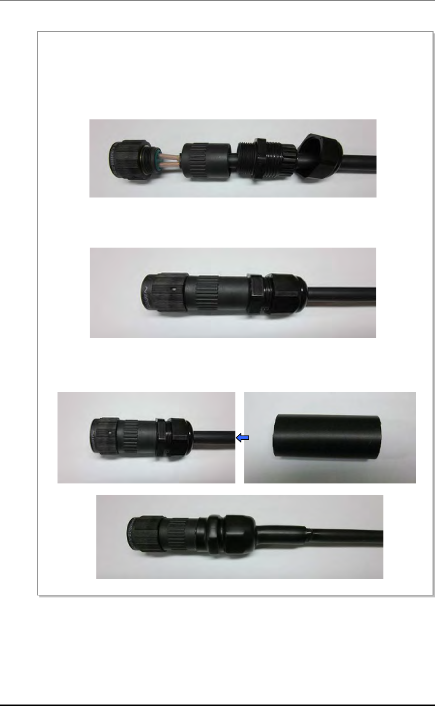
ANNEX C. Connector Assembly
C-16 © SAMSUNG Electronics Co., Ltd.
Figure C.14 Power Connector Assembly (2)
5) Insert the connector pin assembled with the power cable into the end of connector. The pin map of
connector end and cable is as below.
- C: -48 VDC/Black
- D: Return/White
Push the pin into the end and check if it does not pull off.
6) After connecting the connector end and the pin assembled with the cable, assemble the connector parts
to the connector end one by one.
7) Place the heat shrink tube [38 mm (1.50 in.)] to the lead-in part of connector cable, and shrink it using
the heating gun. Do not shrink the tube for too long time since the jelly might come out too much.
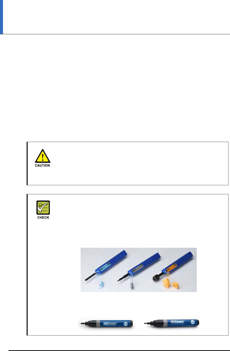
Mobile WiMAX/TD-LTE RRH-2WB Installation Manual
© SAMSUNG Electronics Co., Ltd. D-1
ANNEX D. Cleaning Optic Connector
D.1 Cleaning Optic Connector
When connecting optical cable to the system, performance of system can be decreased or
fails can occur if core section of optical connector is dirty due to dust or foreign material.
Therefore, worker should clean the optic connector before connecting optic cable to the
system to prevent this phenomenon.
This manual describes the method that cleans optic connector when using the IBCTM Brand
cleaner.
Caution When Connecting the Optical Cable
When connecting the optical cable, be careful to keep the cutting section of the
connector core away from dust or foreign material.
If the cable is soiled with foreign material, do not blow to remove them. Make sure
to clean the connector in accordance with the cleaning directions below.
When using Optic Connector Cleaner
When using optic connector cleaner, use the products shown in the example
below or their equivalents.
Ex) Manufacturer-USCONEC (http://www.usconec.com)
- IBCTM Brand Cleaner (P/N: 9393): For LC-LC and MU Connector Cleaning
- IBCTM Brand Cleaner (P/N: 9392): For SC Connector Cleaning
- IBCTM Brand Cleaner (P/N: 12910): For ODC Connector Cleaning
Manufacturer-TheFibers (www.thefibers.com)
- HuxCleaner 1.25 mm (0.05 in.)Type: For LC and MU Connector Cleaning
- HuxCleaner 2.5 mm (0.10 in.) Type: For SC, FC and ST Connector Cleaning
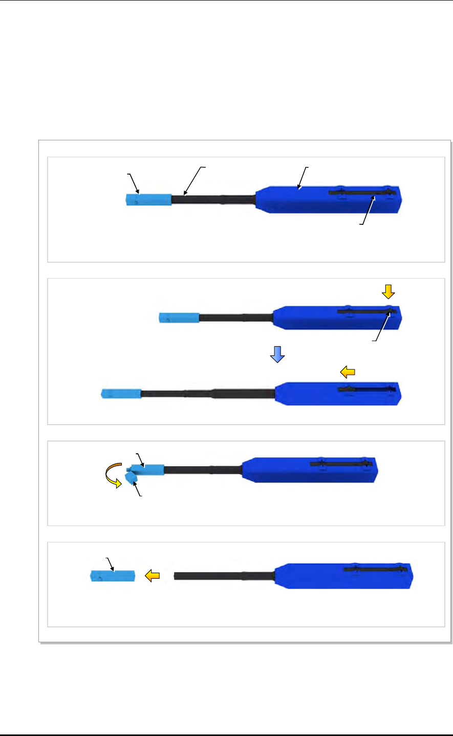
ANNEX D. Cleaning Optic Connector
D-2 © SAMSUNG Electronics Co., Ltd.
D.2 IBCTM Brand Cleaner
Method that uses IBCTM Brand Cleaner is as follows:
D.2.1 IBCTM Brand Type Cleaner (P/N 9393)
Method that uses IBCTM Brand Cleaner for LC-LC and MU connector is as follows:
Figure D.1 Optic Connector Cleaner (IBCTM Brand Type Cleaner: P/N 9393)
Outer Shell
[Optic Connector Cleaner Configuration]
Nozzle
Guide Cap
Lock Button
(for Extend Nozzle)
[Nozzle Extension]
[In Case of LC type Connector (Plug)]
Guide Cap
Guide Cap Cover
[In Case of LC type Connector (Jack)]
Guide Cap
Lock Button
(for Extend Nozzle)
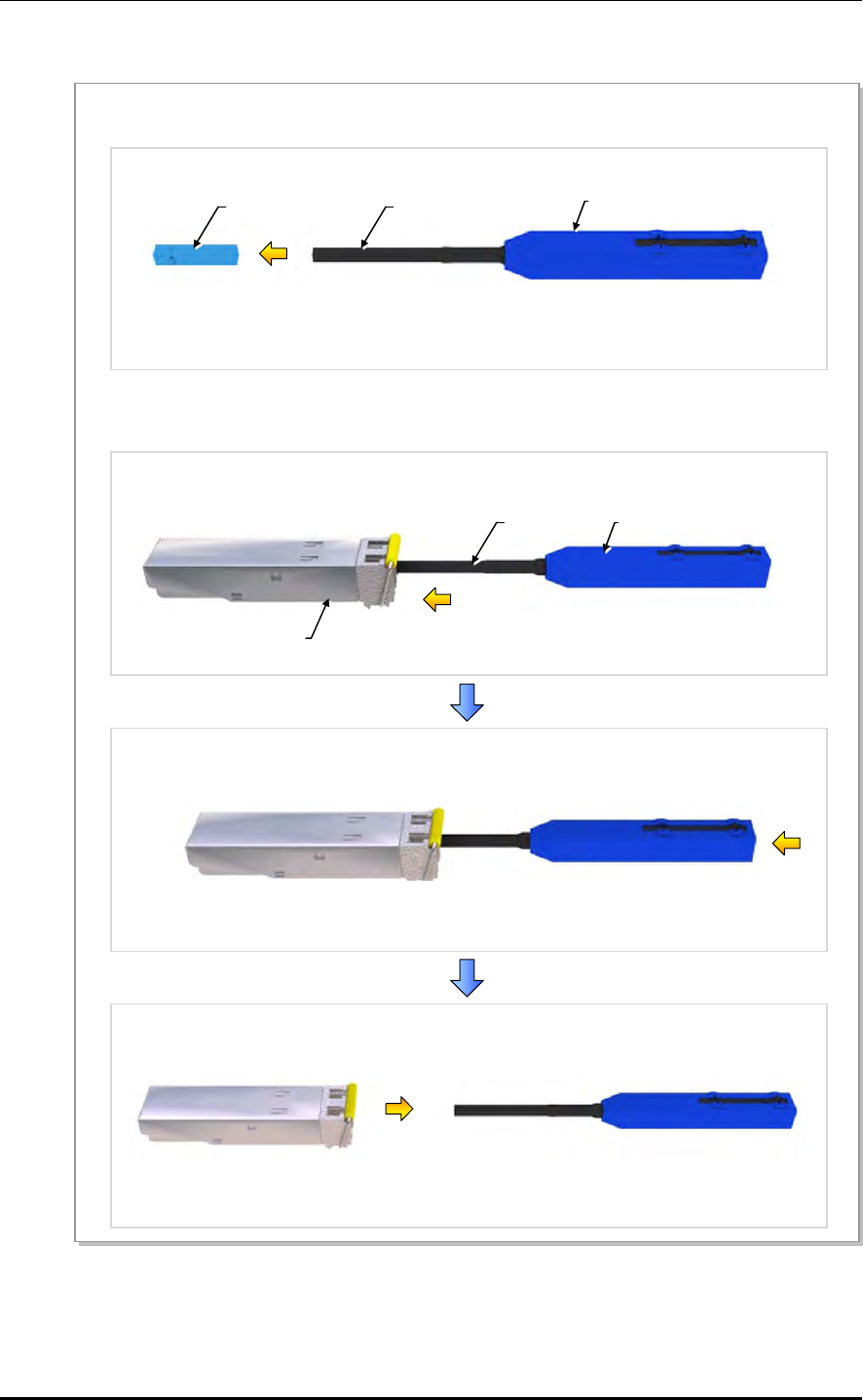
Mobile WiMAX/TD-LTE RRH-2WB Installation Manual/Ver.2.0
© SAMSUNG Electronics Co., Ltd. D-3
Optic Module Cleaning (LC Type Jack)
Figure D.2 Optic Module Cleaning (LC Type Jack)
Guide Cap
1) To clean the optic module, remove the guide cap from the cleaner (P/N: 9393).
2) Insert a cleaner guide cap to every core of the optic module. Clean it by pushing the outer shell
toward the nozzle until you hear the sound of the detergent being sprayed. (Repeat once or twice.)
Outer Shell
Nozzle
Nozzle Outer Shell
Optic Module
[IBC Brand Cleaner: P/N 9393]
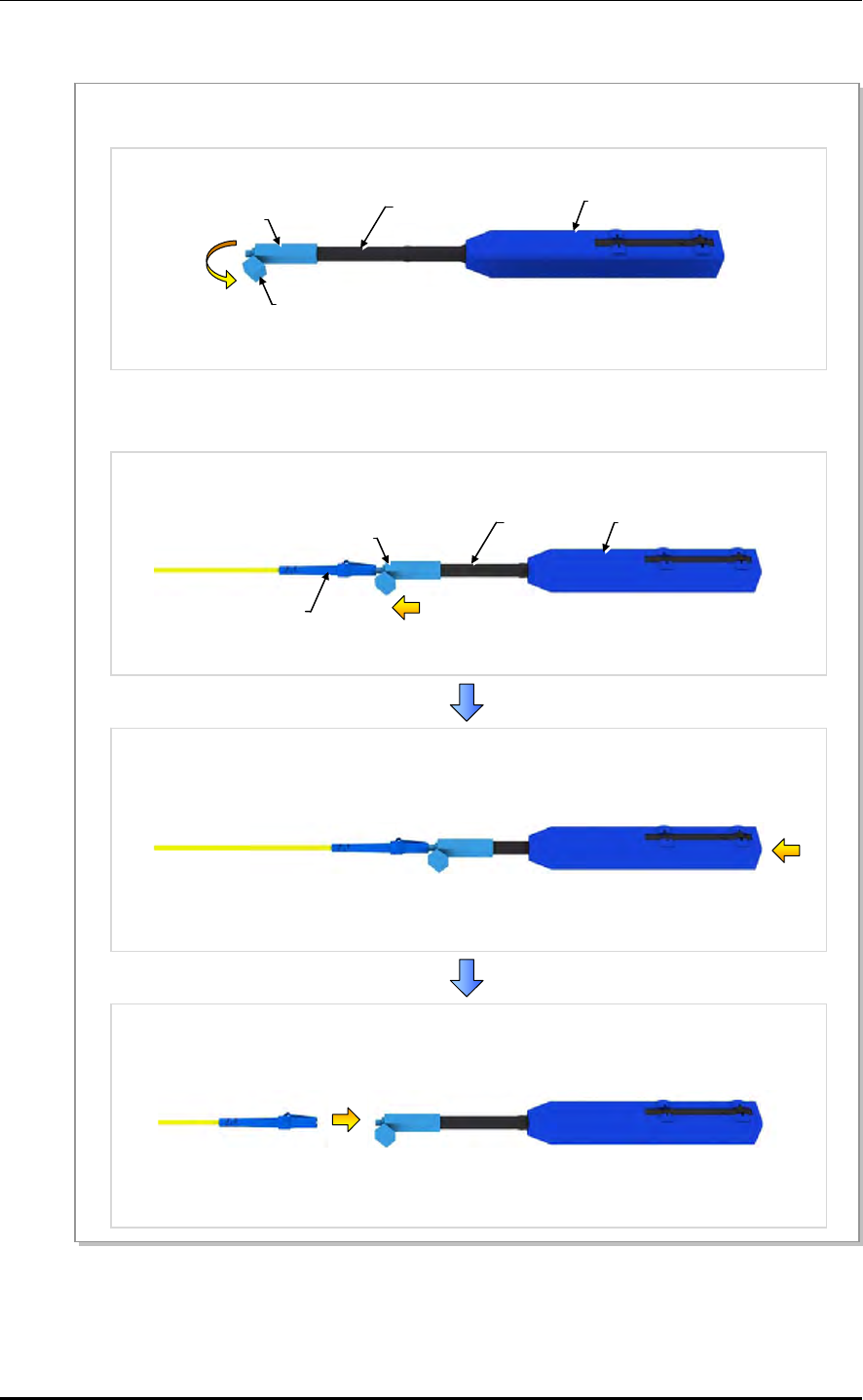
ANNEX D. Cleaning Optic Connector
D-4 © SAMSUNG Electronics Co., Ltd.
Optic Cable Connector Cleaning (LC Type Plug)
Figure D.3 Optic Cable Connector Cleaning (LC Type Plug)
Guide Cap
Guide Cap Cover
1) To clean the optic cable connector, open the guide cap cover from the cleaner (P/N: 9393).
2) Insert a cleaner guide cap to every core of the optic cable connector. Clean it by pushing the outer shell
toward the nozzle until you hear the sound of the detergent being sprayed. (Repeat once or twice.)
Outer Shell
Nozzle
Guide Cap Nozzle Outer Shell
LC Type Connecto
r
[IBC Brand Cleaner: P/N 9393]
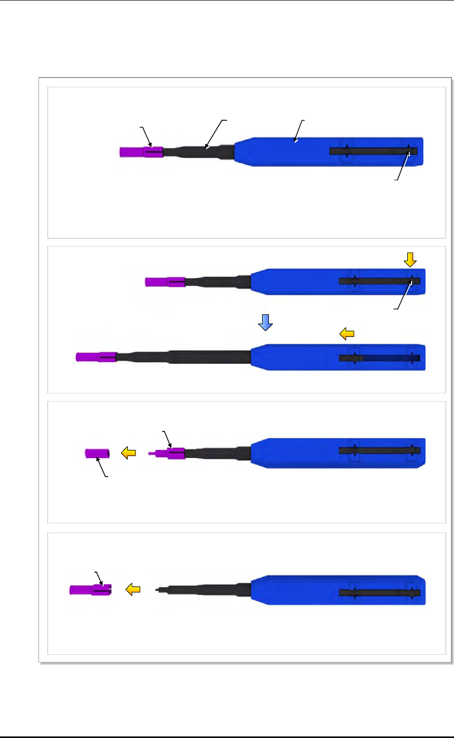
Mobile WiMAX/TD-LTE RRH-2WB Installation Manual/Ver.2.0
© SAMSUNG Electronics Co., Ltd. D-5
D.2.2 IBCTM Brand Type Cleaner (P/N 12910)
Method that uses IBCTM Brand Cleaner for ODC connector is as follows:
Figure D.4 Optic Connector Cleaner (IBCTM Brand Type Cleaner: P/N 12910)
Outer Shell
[Optic Connector Cleaner Configuration]
Nozzle
Guide Cap
Lock Button
(for Extend Nozzle)
[Nozzle Extension]
[In Case of LC type Connector (Plug)]
Guide Cap
Guide Cap Cover
[In Case of LC type Connector (Jack)]
Guide Cap
Lock Button
(for Extend Nozzle)
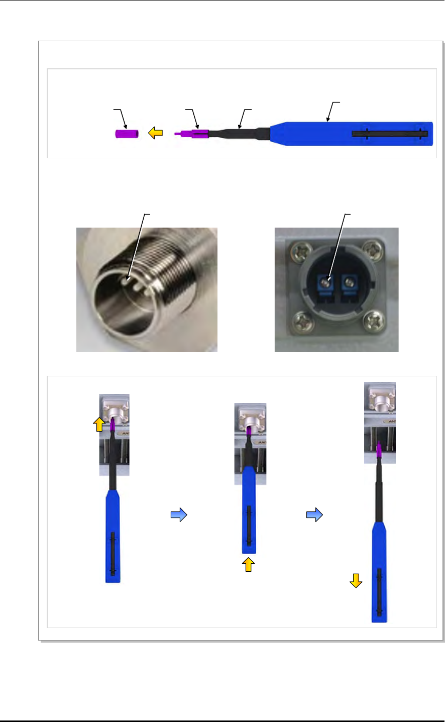
ANNEX D. Cleaning Optic Connector
D-6 © SAMSUNG Electronics Co., Ltd.
Optic Port Cleaning (ODC, PT/LC Jack)
Figure D.5 Optic Port Cleaning (ODC, PT/LC Jack)
[Optic Port of System: ODC-4]
1) To clean the optic port of system, remove the guide cap from the cleaner.
Guide Cap
2) Insert a cleaner guide cap to every core hole of the system’s optic port. Clean it by pushing the outer
shell toward the nozzle until you hear the sound of the detergent being sprayed. (Repeat once or twice.)
Outer Shell
Nozzle
Core
Guide Cap Cove
r
[Optic Port of System: PT/LC]
Core
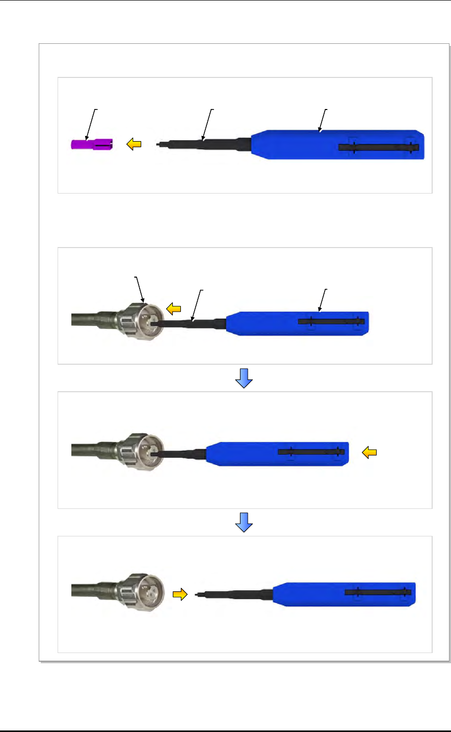
Mobile WiMAX/TD-LTE RRH-2WB Installation Manual/Ver.2.0
© SAMSUNG Electronics Co., Ltd. D-7
Optic Cable Connector Cleaning (ODC Type Plug)
Figure D.6 Optic Cable Connector Cleaning (ODC Type Plug)
Guide Cap
1) To clean the ODC connector of cable, remove the guide cap from the cleaner (P/N: 12910).
2) Insert a cleaner guide cap to every core hole of the ODC connector. Clean it by pushing the outer shell
toward the nozzle until you hear the sound of the detergent being sprayed. (Repeat once or twice.)
Outer Shell
Nozzle
Outer Shell
Nozzle
ODC Connecto
r
[IBC Brand Cleaner: P/N 12910]
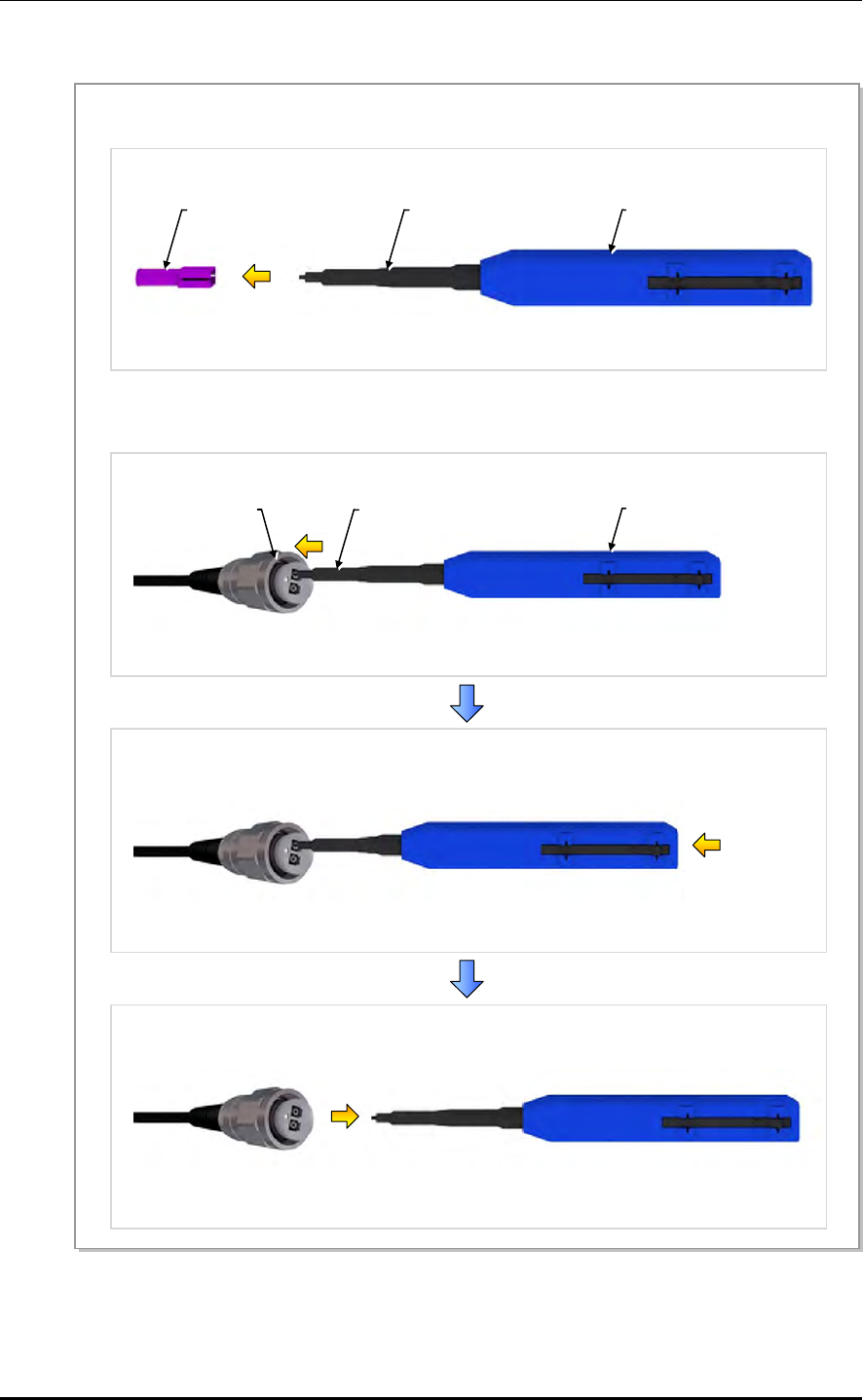
ANNEX D. Cleaning Optic Connector
D-8 © SAMSUNG Electronics Co., Ltd.
Optic Cable Connector Cleaning (PT/LC Type Plug)
Figure D.7 Optic Cable Connector Cleaning (PT/LC Type Plug)
Guide Cap
1) To clean the PT/LC connector of cable, remove the guide cap from the cleaner (P/N: 12910).
2) Insert a cleaner guide cap to every core hole of the the PT/LC connector. Clean it by pushing the outer
shell toward the nozzle until you hear the sound of the detergent being sprayed. (Repeat once or twice.)
Outer Shell
Nozzle
Outer Shell
Nozzle
PT/LC Connecto
r
[IBC Brand Cleaner: P/N 12910]

Mobile WiMAX/TD-LTE RRH-2WB Installation Manual/Ver.2.0
© SAMSUNG Electronics Co., Ltd. D-9
Measuring the Optical Output and Connecting the Optic Connector
Figure D.8 Measuring the Optical Output and Connecting the Optic Connector
[Optic Powermeter]
1) Check the optical output again using an optic power meter.
2) If the optical output measurement result meets the reference value, clean the connector again and
connect it. If the measurement result does not meet the reference value, discard the cable, replace it
with a new cable, and then clean the new one and connect it to the system.
[LC/PC Plug]
[PT/LC Plug]
[ODC Plug]
[Harting Plug]

ANNEX D. Cleaning Optic Connector
D-10 © SAMSUNG Electronics Co., Ltd.
This page is intentionally left blank.
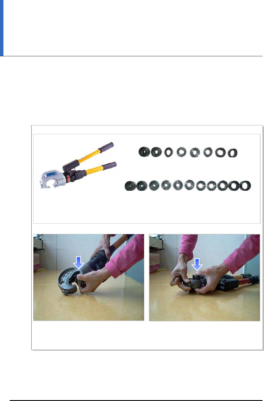
Mobile WiMAX/TD-LTE RRH-2WB Installation Manual
© SAMSUNG Electronics Co., Ltd. E-1
ANNEX E. Pressure Terminal
Assembly
Method that assembles the pressure terminal by using the crimp-type compressor is as
follows:
Figure E.1 Pressure Terminal Assembly (1)
[Ring Type Dies]
[Hex. Type Dies]
[Hydraulic Pressure
Terminal Compressor]
1) Select the appropriate compressor and dies for the cable specification and pressure type.
2) Attach the cable and dies satisfying the pressure
terminal specification to the lower section of the
compressor terminal.
3) Attach the cable and dies satisfying the pressure
terminal specification to the upper section of the
compressor terminal.
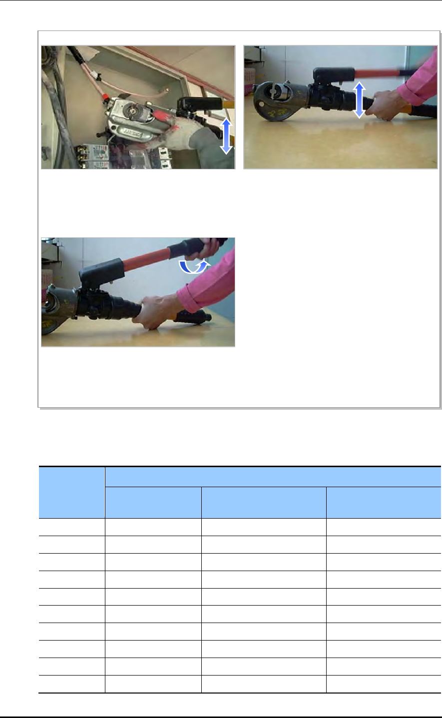
ANNEX E. Pressure Terminal Assembly
E-2 © SAMSUNG Electronics Co., Ltd.
Figure E.2 Pressure Terminal Assembly (2)
Table E.1 Compressor Specification by Cable Thickness
Cable Spec.
(mm2)
Compressor Specification
Small-size Hand
Compressor
Large-size Hand
Compressor (AK-38, 100)
Hydraulic Compressor
(IZUMI Hex. Type Dies)
2.5 2 X X
4 2 X X
6 5.5 X X
10 8 8 X
16 14 14 16
25 22 22 25
35 38 38 35
50 X 60 50
70 X 80 70
95 X 100 95~300
4) Insert the pressure terminal into the compressor
lock and press gently.
5) Unsheathe the cable and insert the high pressure
heat shrink tube that fits the cable into the
pressure terminal attached to the compressor.
By moving the compressor lever up and down,
firmly connect the cable to the pressure terminal.
6) Once the pressure terminal assembly is complete,
turn the compressor lever handle to the right to
unlock it, and remove the pressure terminal
attached to the cable.
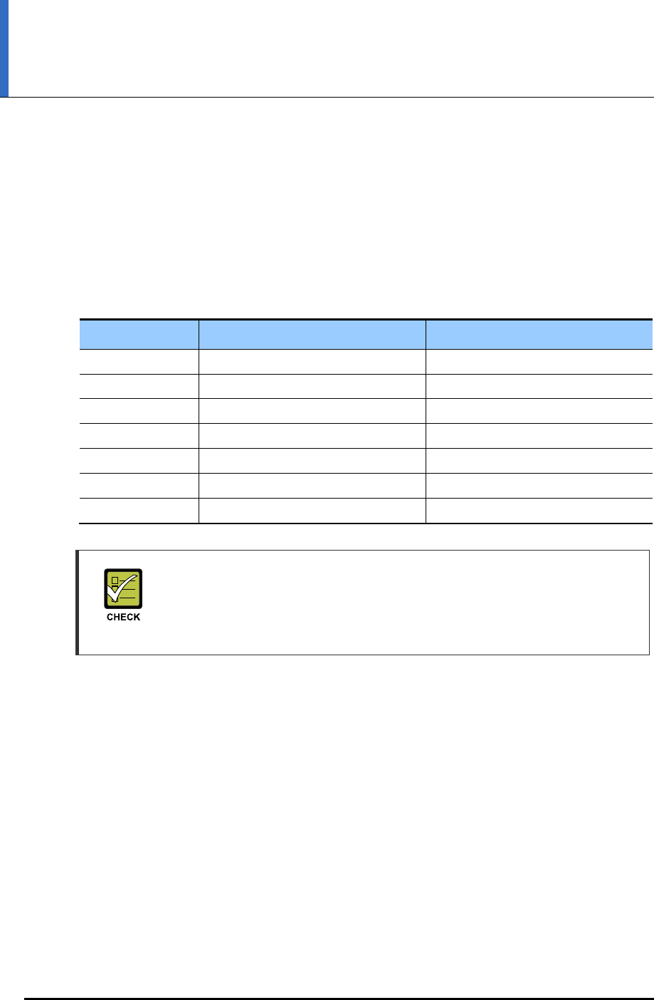
Mobile WiMAX/TD-LTE RRH-2WB Installation Manual
© SAMSUNG Electronics Co., Ltd. F-1
ANNEX F. Standard Torque
When you tighten the bolt, refer to the standard torque value below to prevent the
equipment and bolt from damage and secure by tightening. When the torque value for each
connection part is defined already, refer to the defined value.
Table F.1 Standard Torque Value for Tightening Bolts
Bolt Spec. Torque Value (kgf.cm) Torque Value (lbf.ft)
M3 4.08~6.12 0.29~0.44
M4 9.52~14.28 0.69~1.03
M5 20.0~30.0 1.45~2.17
M6 33.28~49.92 2.41~3.61
M8 82.4~123.6 5.96~8.94
M10 166.4~249.6 12.03~18.05
M12 292.0~438.0 21.11~31.67
Checking Standard Torque Value
Torque value can be different, defending on the material, characteristic and
specification of the equipment and fixing material. Make sure to check the proper
torque value for each specification of the equipment and fixing material.

ANNEX F. Standard Torque
F-2 © SAMSUNG Electronics Co., Ltd.
This page is intentionally left blank.

Mobile WiMAX/TD-LTE RRH-2WB Installation Manual
© SAMSUNG Electronics Co., Ltd. I
ABBREVIATION
L
LTE Long Term Evolution
M
MGB Main Ground Bar
MIMO Multiple Input Multiple Output
MIP Mobile IP
N
NE Network Element
P
PIMD Passive Inter-Modulation Distortion
R
RSSI Received Signal Strength Indicator
RRH Remote RF Head
T
TGB Tower Ground Bar
V
VSWR Voltage Standing Waveform Ratio

MPE Information
ⓒ SAMSUNG Electronics Co., Ltd.
Warning: Exposure to Radio Frequency Radiation The radiated output power
of this device is far below the FCC radio frequency exposure limits.
Nevertheless, the device should be used in such a manner that the potential
for human contact during normal operation is minimized. In order to avoid
the possibility of exceeding the FCC radio frequency exposure limits, human
proximity to the antenna should not be less than 900cm during normal
operation. The gain of the antenna is 19.8 dBi.The antenna(s) used for this
transmitter must not be co-located or operating in conjunction with any other
antenna or transmitter.

Mobile WiMAX/TD-LTE RRH-2WB
Installation Manual
©2012 Samsung Electronics Co., Ltd.
All rights reserved.
Information in this manual is proprietary to SAMSUNG
Electronics Co., Ltd.
No information contained here may be copied, translated,
transcribed or duplicated by any form without the prior written
consent of SAMSUNG.
Information in this manual is subject to change without notice.