Samsung Electronics Co SLS-BD106Q RRH (Remote Radio Head) User Manual 1
Samsung Electronics Co Ltd RRH (Remote Radio Head) 1
UserManual.wiki
>
Samsung Electronics Co
>
SLS-BD106Q User Manual
>
User Manual 1
Contents
1.
User Manual
2.
User Manual 1
3.
User Manual 2
User Manual 1
Navigation menu
Upload a User Manual
Namespaces
Wiki Guide
HTML
PDF
Info
Views
User Manual
Discussion / Help
Navigation
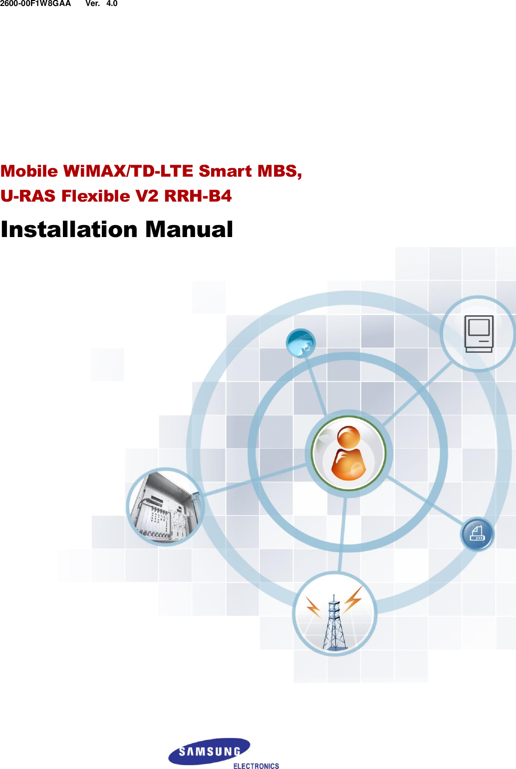
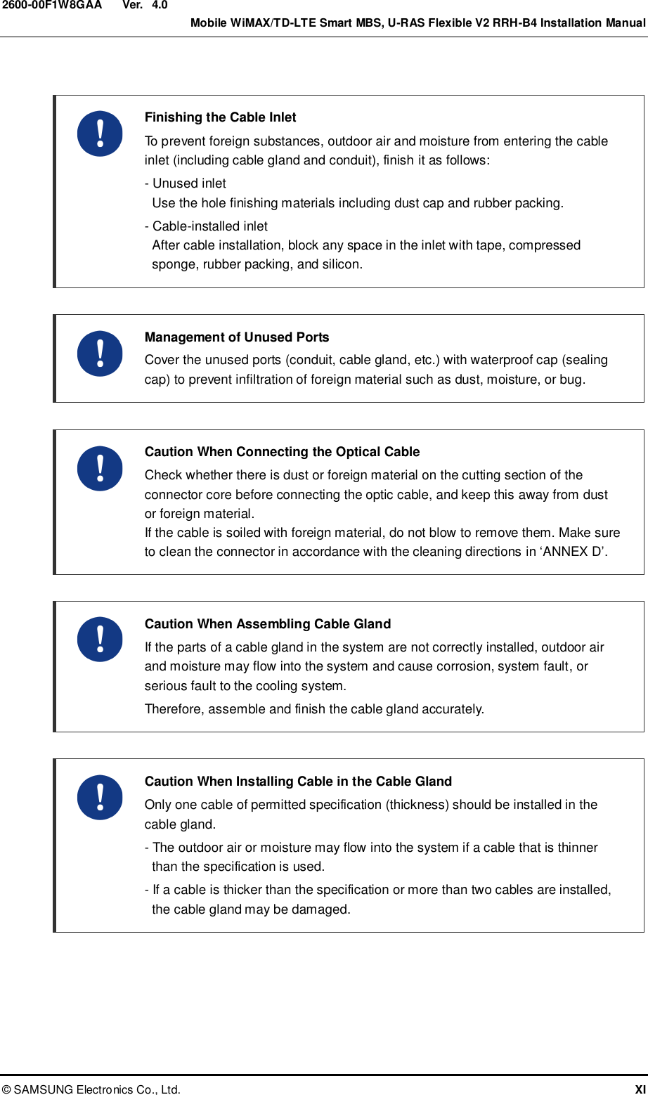
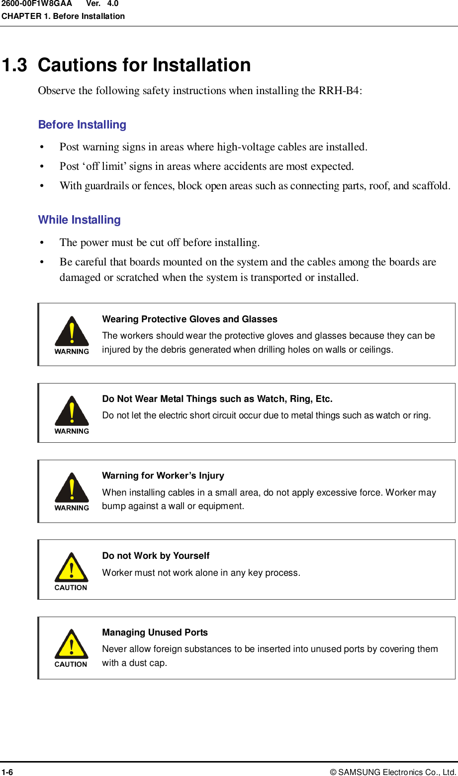
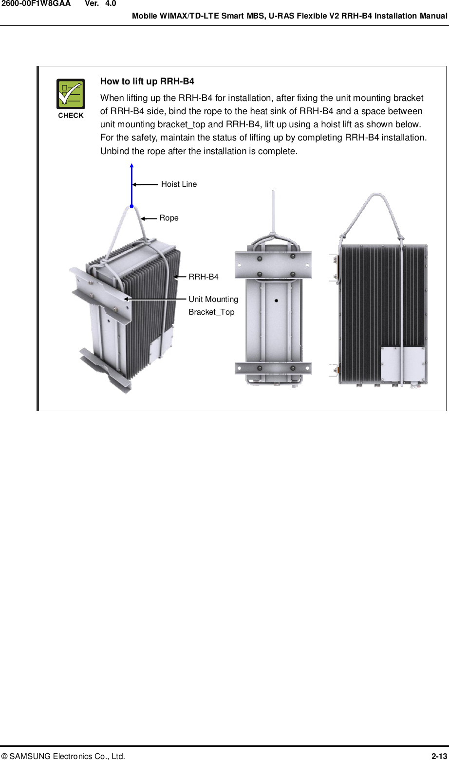
![Ver. Mobile WiMAX/TD-LTE Smart MBS, U-RAS Flexible V2 RRH-B4 Installation Manual © SAMSUNG Electronics Co., Ltd. 1-1 2600-00F1W8GAA 4.0 CHAPTER 1. Before Installation 1.1 System Configuration RRH-B4 Configuration The configuration of RRH-B4 is as follows: Figure 1.1 RRH-B4 Configuration 13.78 (350) [Front View] [Right View] [Left View] [Rear View] Unit: in. (mm) 21.65 (550) [Bottom View] [Top View] 8.17 (207.5) 13.78 (350)](https://usermanual.wiki/Samsung-Electronics-Co/SLS-BD106Q.User-Manual-1/User-Guide-1865351-Page-23.png)
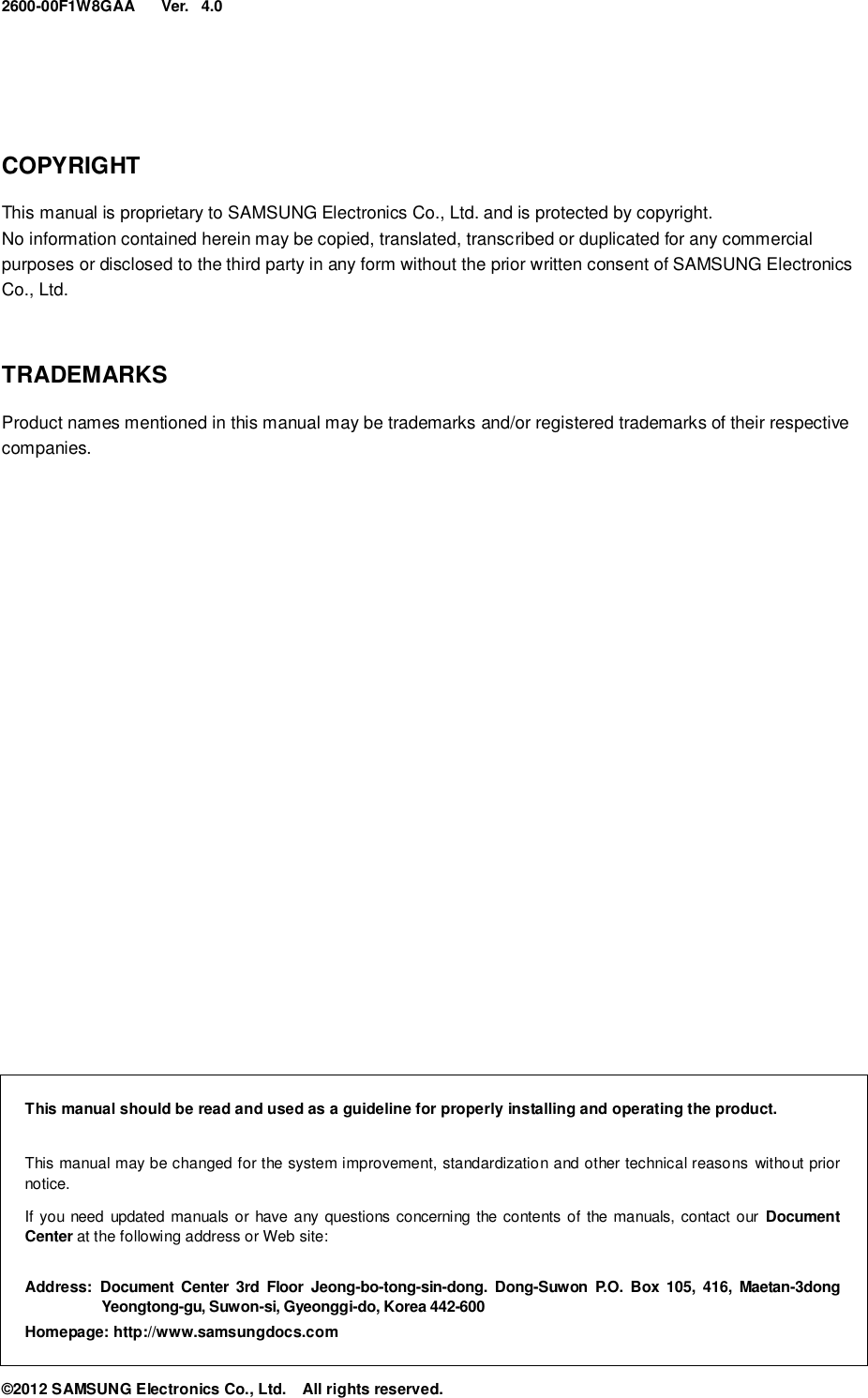
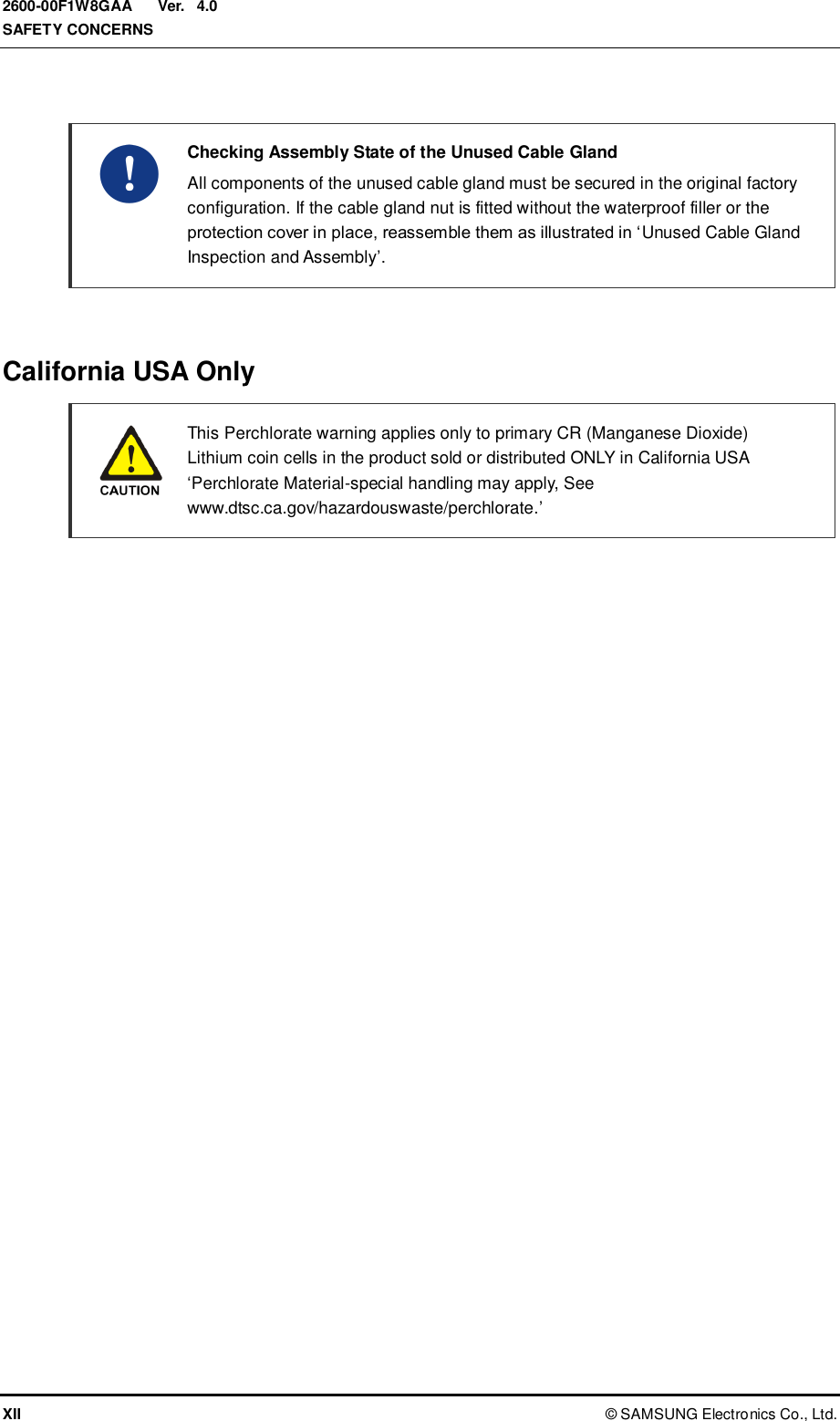
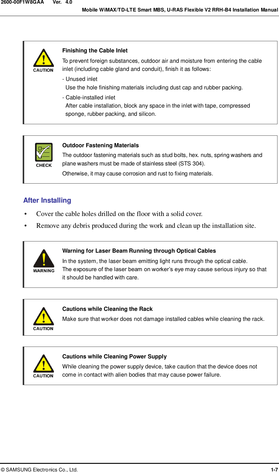
![Ver. CHAPTER 1. Before Installation 1-2 © SAMSUNG Electronics Co., Ltd. 2600-00F1W8GAA 4.0 External Interface of RRH-B4 The external interface structure of RRH-B4 is as follows: Figure 1.2 External Interface of RRH-B4 [Bottom View] DC Power (Gland M25: 22553y16) RET ANT_0 Optic (Gland M25: 22553y8) Ground Terminal ANT_1 ANT_2 ANT_3](https://usermanual.wiki/Samsung-Electronics-Co/SLS-BD106Q.User-Manual-1/User-Guide-1865351-Page-24.png)
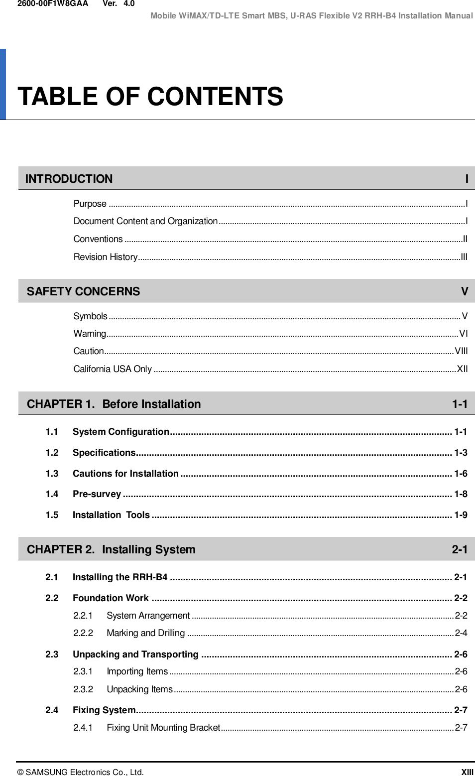
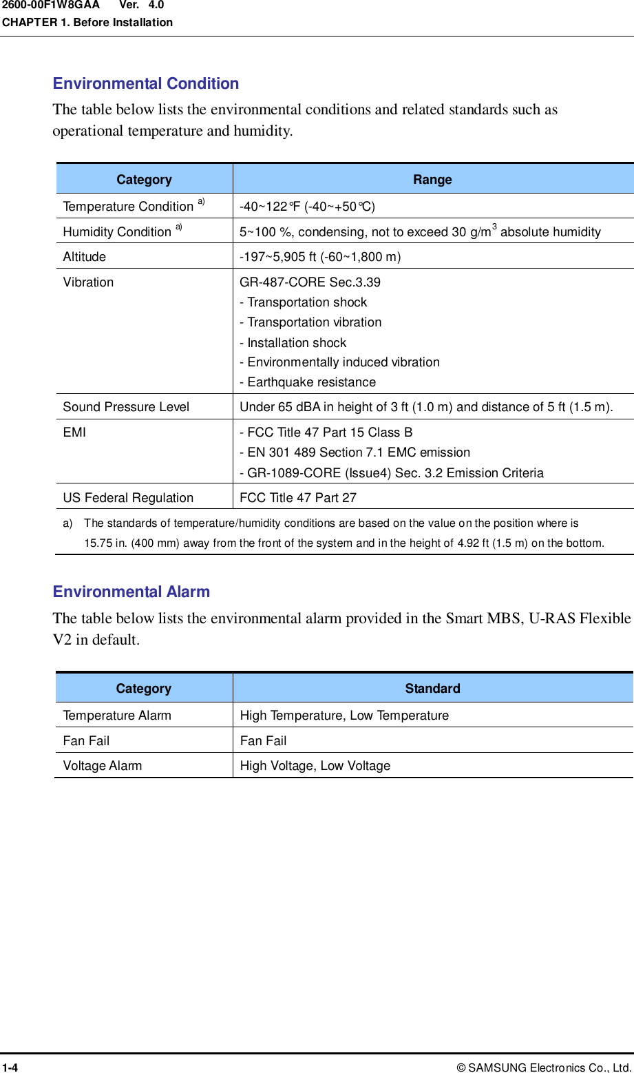
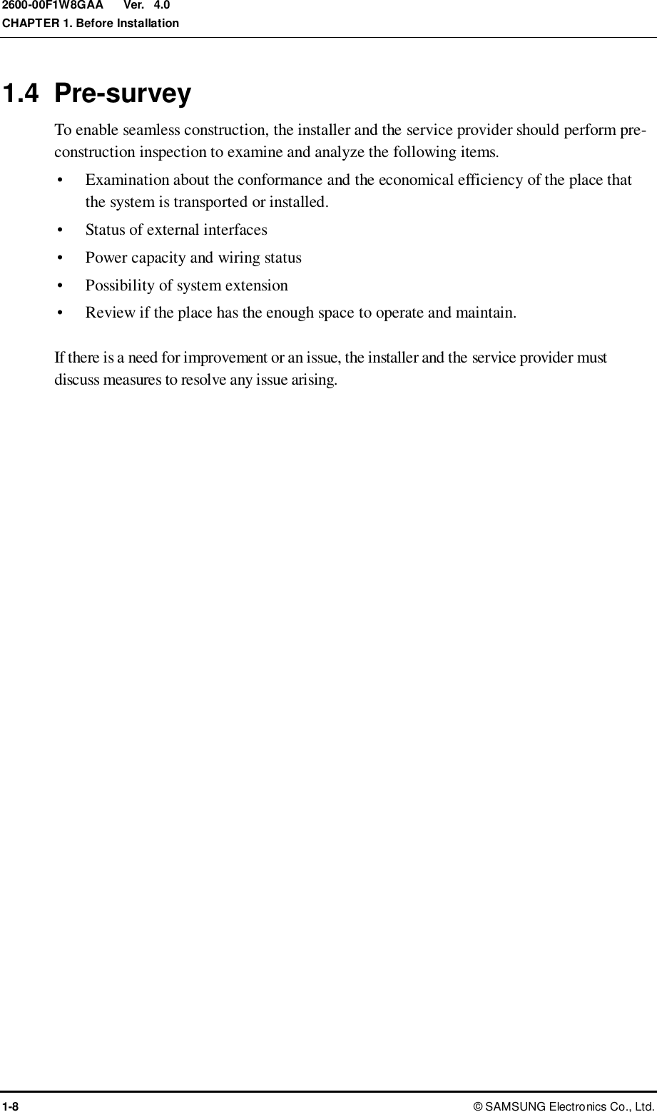
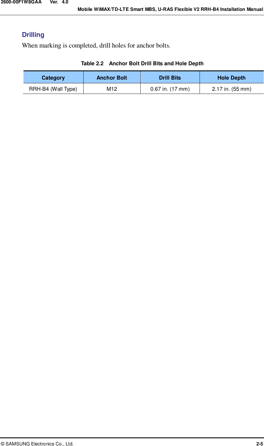
![Ver. Mobile WiMAX/TD-LTE Smart MBS, U-RAS Flexible V2 RRH-B4 Installation Manual © SAMSUNG Electronics Co., Ltd. 1-3 2600-00F1W8GAA 4.0 1.2 Specifications Main Specifications The table below lists the main specifications of the system. Category System Capacity Air specification WiMAX/TD-LTE Channel Bandwidth - Mobile WiMAX: 10 MHz - TD-LTE: 20 MHz Operating Frequency 2,496~2,690 MHz (BC41) RRH-B4 Capacity - WiMAX 4 Carriers - TD-LTE 2 Carriers Interface between DU and RRH-B4 - WiMAX: 1.25 Gbps CPRI - TD-LTE: 2.5 Gbps CPRI Output Antenna port based - WiMAX: 5 W/Carrier/Path - TD-LTE: 20 W/Carrier/Path Input Power The table below lists the power standard for the RRH-B4. The RRH-B4satisfies the electrical safety standard prescribed in UL60950. If an operator wants to use AC system input voltage, the operator can supply power using an external rectifier (provided by a service provider). Category Standard System Input Voltage -48 VDC (Voltage Variation Range: -40~-56 VDC) System Consumption Current 9.27 A AVG. @ 48 V, 28: 18 (DL UL ratio) * Each of the DU (UADU) and RRH-B4 receives -48 VDC of power for its operation. Unit Size and Weight The table below lists the size and weight of the RRH-B4. Category Standard Size [W × D × H, in. (mm)] 13.8 (350) × 8 (207.5) × 21.7 (550) Weight [lb (kg)] About 50.7 (23)](https://usermanual.wiki/Samsung-Electronics-Co/SLS-BD106Q.User-Manual-1/User-Guide-1865351-Page-25.png)
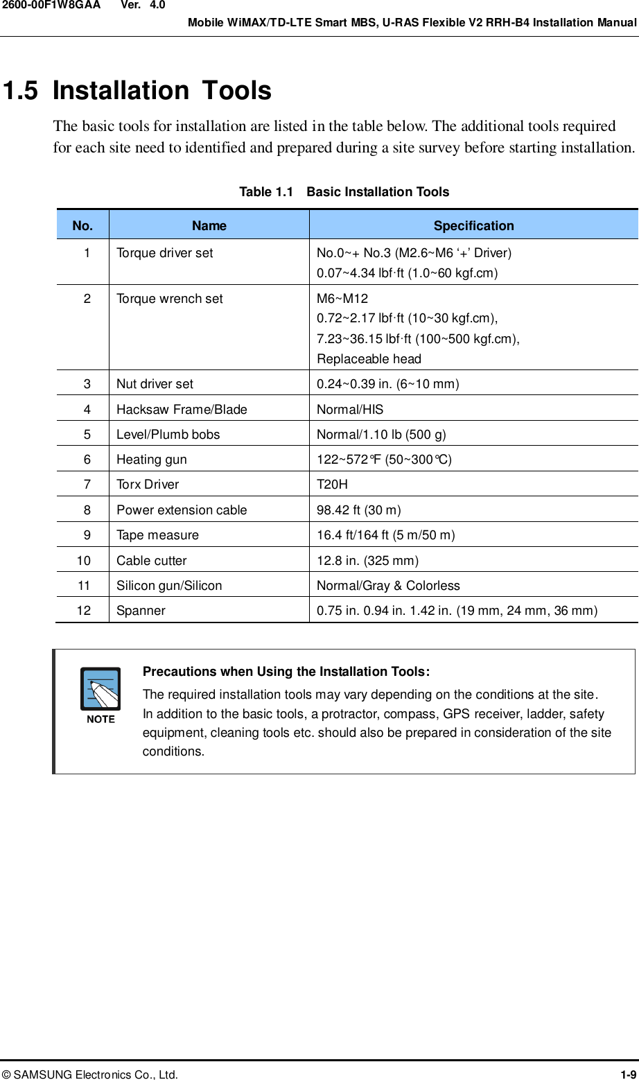
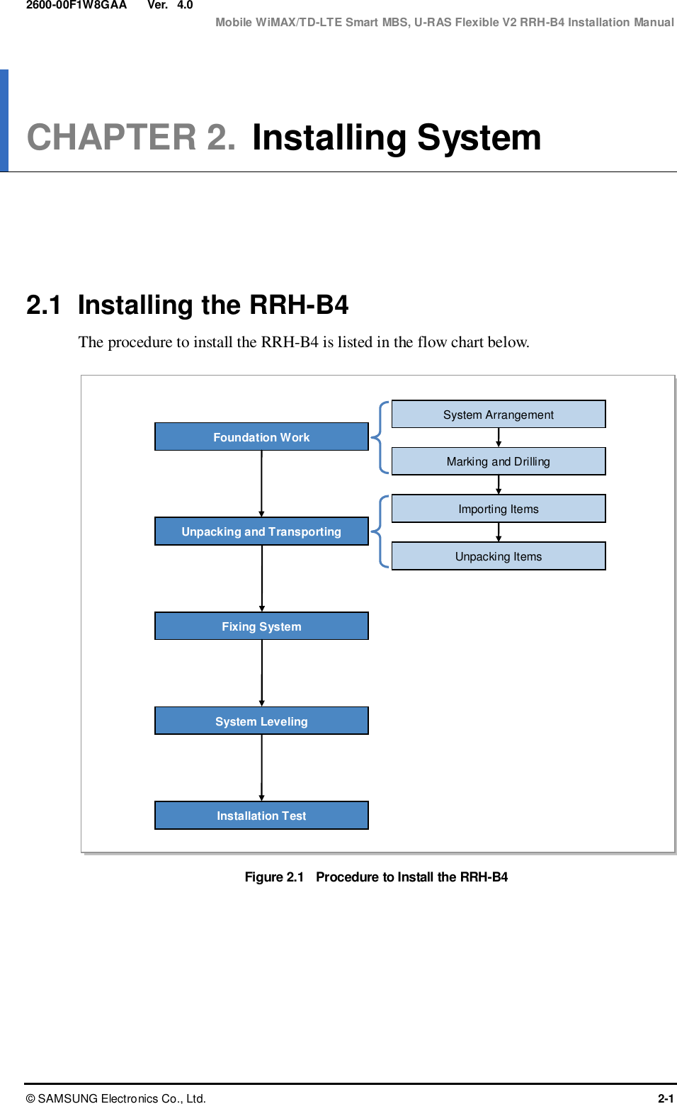
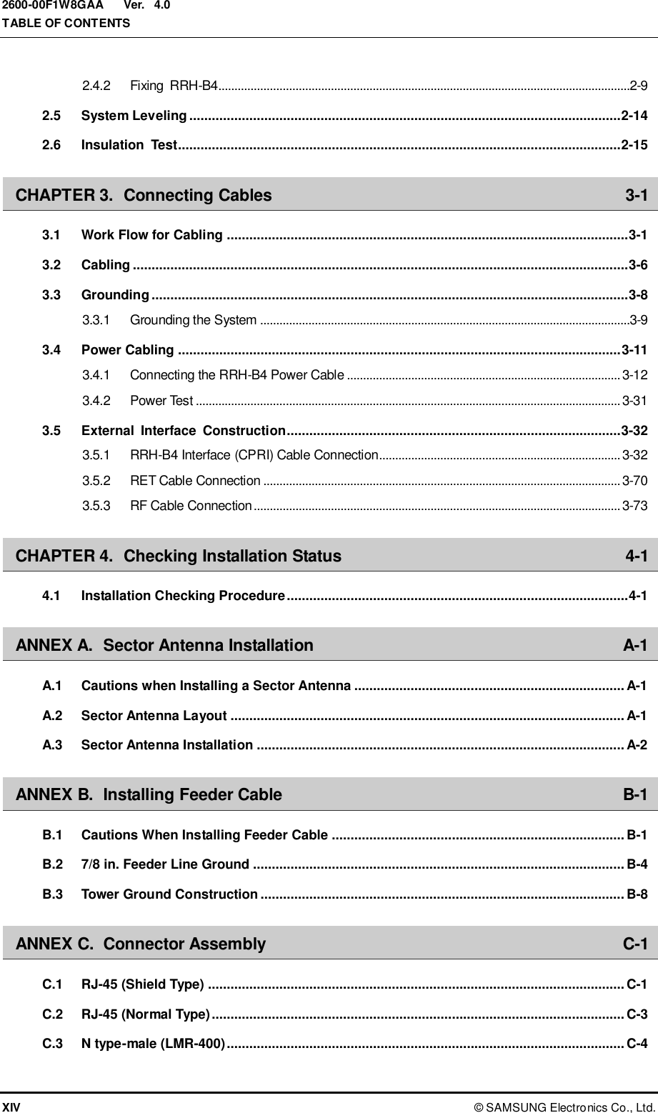
![Ver. CHAPTER 2. Installing System 2-2 © SAMSUNG Electronics Co., Ltd. 2600-00F1W8GAA 4.0 2.2 Foundation Work 2.2.1 System Arrangement A minimum distance must be secured around the RRH-B4, in each direction for installation and maintenance. Table 2.1 Recommended Distances for RRH-B4 Installation Category Recommended Distances Front/Rear 31.5 in. (800 mm) or more Side 23.62 in. (600 mm) or more Figure 2.2 RRH-B4 Arragement (Wall Type) [Left View] 15.35 (390) [Top View] 21.65 (550) 8.17 (207.5) Unit: in. (mm)](https://usermanual.wiki/Samsung-Electronics-Co/SLS-BD106Q.User-Manual-1/User-Guide-1865351-Page-34.png)
![Ver. Mobile WiMAX/TD-LTE Smart MBS, U-RAS Flexible V2 RRH-B4 Installation Manual © SAMSUNG Electronics Co., Ltd. 2-3 2600-00F1W8GAA 4.0 Figure 2.3 RRH-B4 Arragement (Sector Pole Type) System Installation Spaces The space specifications in the figure above apply when the pole diameter is 3 in. (76.3 mm). The dimensions may vary depending on the diameter of the pole. [Front View] 13.78 (350) [Top View] 21.65 (550) 11.81 (300) Unit: in. (mm) 5.57 (141.6)](https://usermanual.wiki/Samsung-Electronics-Co/SLS-BD106Q.User-Manual-1/User-Guide-1865351-Page-35.png)
![Ver. CHAPTER 2. Installing System 2-4 © SAMSUNG Electronics Co., Ltd. 2600-00F1W8GAA 4.0 2.2.2 Marking and Drilling Marking Before placing the system, mark the position where the system will be installed and also the positions where anchor bolts will be fixed using an ink line or a pen. Checking Marking (horizontal/vertical) When Mounting the System on Wall If you do the drilling or anchoring on a wall when the positions are not marked to be horizontal or vertical, only limited range of tuning is allowed for leveling after the system is mounted. To mount the system on a wall, perform the leveling test by referring to ‘System Leveling’ to check the positions are marked to be horizontal or vertical before drilling. If the result shows they are not horizontal or vertical, modify the marking positions. Marking Using the System When the position where the system will be placed is determined, place the system on the position and then mark the positions where anchor bolts will be fixed using a pen. This will reduce marking error range caused by a worker. Figure 2.4 System Marking-Wall Type [Rigt View] 15.94 (405) Anchor Bolt Hole (Ф 14) Unit: in. (mm) 8.17 (207.5) 21.65 (550) 10.49 (266.5)](https://usermanual.wiki/Samsung-Electronics-Co/SLS-BD106Q.User-Manual-1/User-Guide-1865351-Page-36.png)
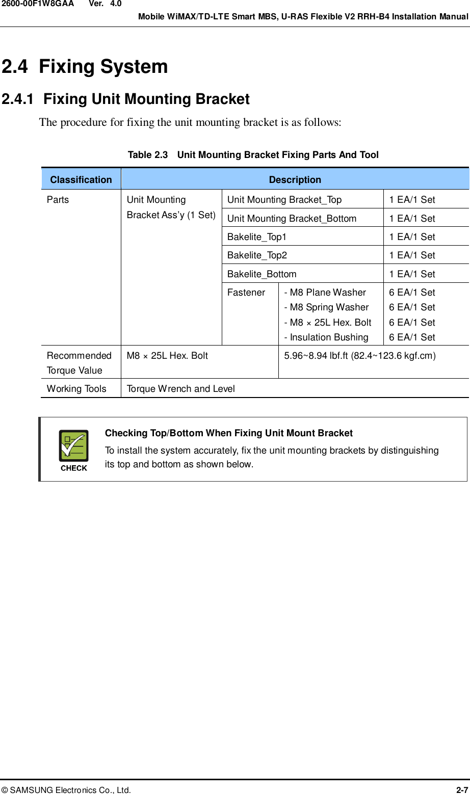
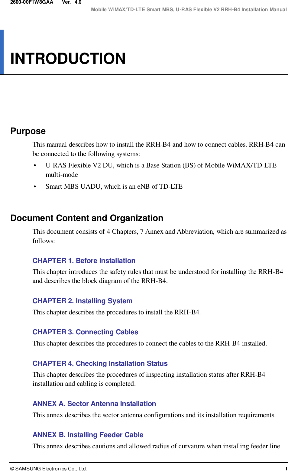
![Ver. CHAPTER 2. Installing System 2-8 © SAMSUNG Electronics Co., Ltd. 2600-00F1W8GAA 4.0 Figure 2.5 Fixing Unit Mounting Bracket 1) Place the bakelite-top 1, 2 and unit mounting bracket_top to the RRH-B4's top fixing holes and fix these firmly with fasteners. 2) Place the bakelite-bottom and unit mounting bracket_bottom to the RRH-B4's bottom fixing holes and fix these firmly with fasteners. Bakelite_Top 2 [Unit Mounting Bracket_Bottom] Left Right 3.13 in. (79.5 mm) 2.24 in. (57 mm) Unit Mounting Bracket_Top M8 Insulation Bushing M8 Plane Washer M8 Spring Washer M8 × 25L Hex. Bolt Bakelite_Top 1 Bakelite-Bottom M8 Insulation Bushing M8 Plane Washer M8 Spring Washer M8 × 25L Hex. Bolt Unit Mounting Bracket_Bottom](https://usermanual.wiki/Samsung-Electronics-Co/SLS-BD106Q.User-Manual-1/User-Guide-1865351-Page-40.png)
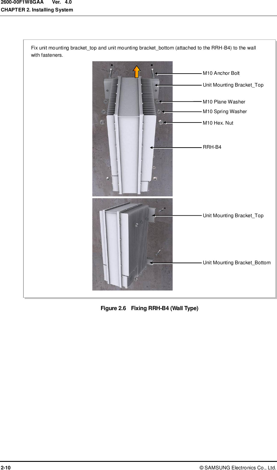
![Ver. CHAPTER 2. Installing System 2-12 © SAMSUNG Electronics Co., Ltd. 2600-00F1W8GAA 4.0 Figure 2.7 Fixing RRH-B4 (Pole Type) Place the RRH-B4 (attaching unit mounting bracket_top, bottom) to the pole front, place the rear bracket to the pole rear, and fix these firmly with fasteners. M12 × 180L Hex. Bolt Pole [Φ 3~4.5 in. (Φ 76.3~114.3 mm)] Unit Mounting Bracket_Top Rear Bracket M12 Plane Washer M12 Spring Washer M12 Hex. Nut Rear Bracket Unit Mounting Bracket_Bottom Left Right 5.69 in. (144.5 mm) 4.8 in. (122 mm) Rear Bracket](https://usermanual.wiki/Samsung-Electronics-Co/SLS-BD106Q.User-Manual-1/User-Guide-1865351-Page-44.png)
![Ver. CHAPTER 2. Installing System 2-14 © SAMSUNG Electronics Co., Ltd. 2600-00F1W8GAA 4.0 2.5 System Leveling Leveling refers to compensating for the level difference on the floor that is generated during floor work to install devices horizontally or vertically. Leveling can be carried out using a vinyl hose, a balance weight, or a level. In this manual, a commonly used method, which uses a spirit level, is described. Leveling Using a Level Leveling method using a level is as follows: Table 2.6 Leveling Using a Level Classification Description Test method The level is measured based on the position of a bubble after attaching the spirit level to the top and side of the system. Evaluation criteria Good Poor If it is leveled, the bubble of the spirit level is positioned at the center of both lines. Corrective measures for poor leveling Use an aid such as bakelite on the back side of the system or an auxiliary fixture to adjust the height. Adjust the position of fasteners used to fix the system or its leveling status. Figure 2.8 Leveling Using a Level (Example) [Measuring Vertical Position] [Measuring Horizontal Position]](https://usermanual.wiki/Samsung-Electronics-Co/SLS-BD106Q.User-Manual-1/User-Guide-1865351-Page-46.png)
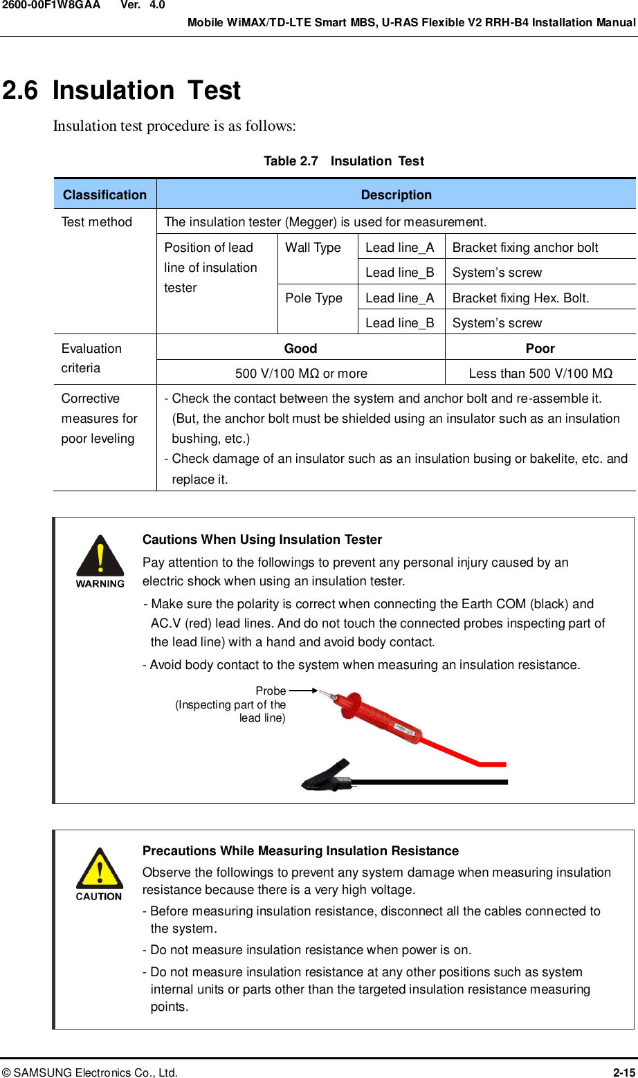
![Ver. CHAPTER 2. Installing System 2-16 © SAMSUNG Electronics Co., Ltd. 2600-00F1W8GAA 4.0 Figure 2.9 Schematic Diagram for Insulation Test (Wall Type) Figure 2.10 Schematic Diagram for Insulation Test (Pole Type)[Megger] [System’s screw] [Bracket Fixing Anchor Bolt] [Megger] [System’s screw] [Bracket Fixing Hex.Bolt]](https://usermanual.wiki/Samsung-Electronics-Co/SLS-BD106Q.User-Manual-1/User-Guide-1865351-Page-48.png)
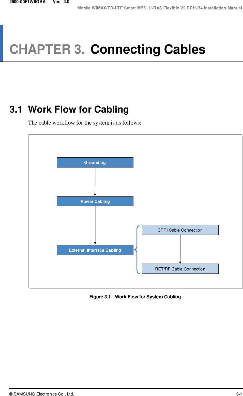
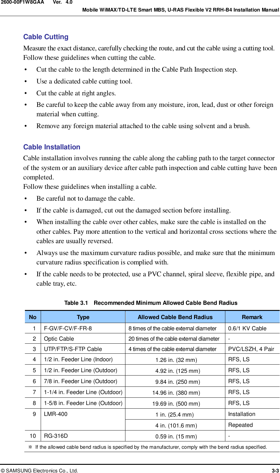
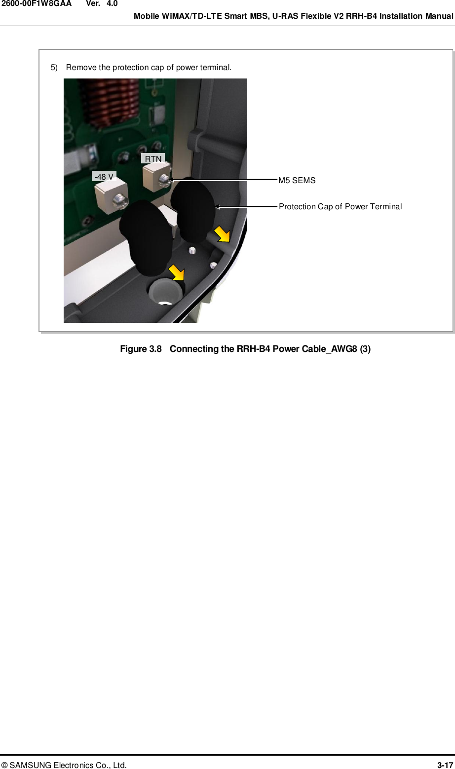
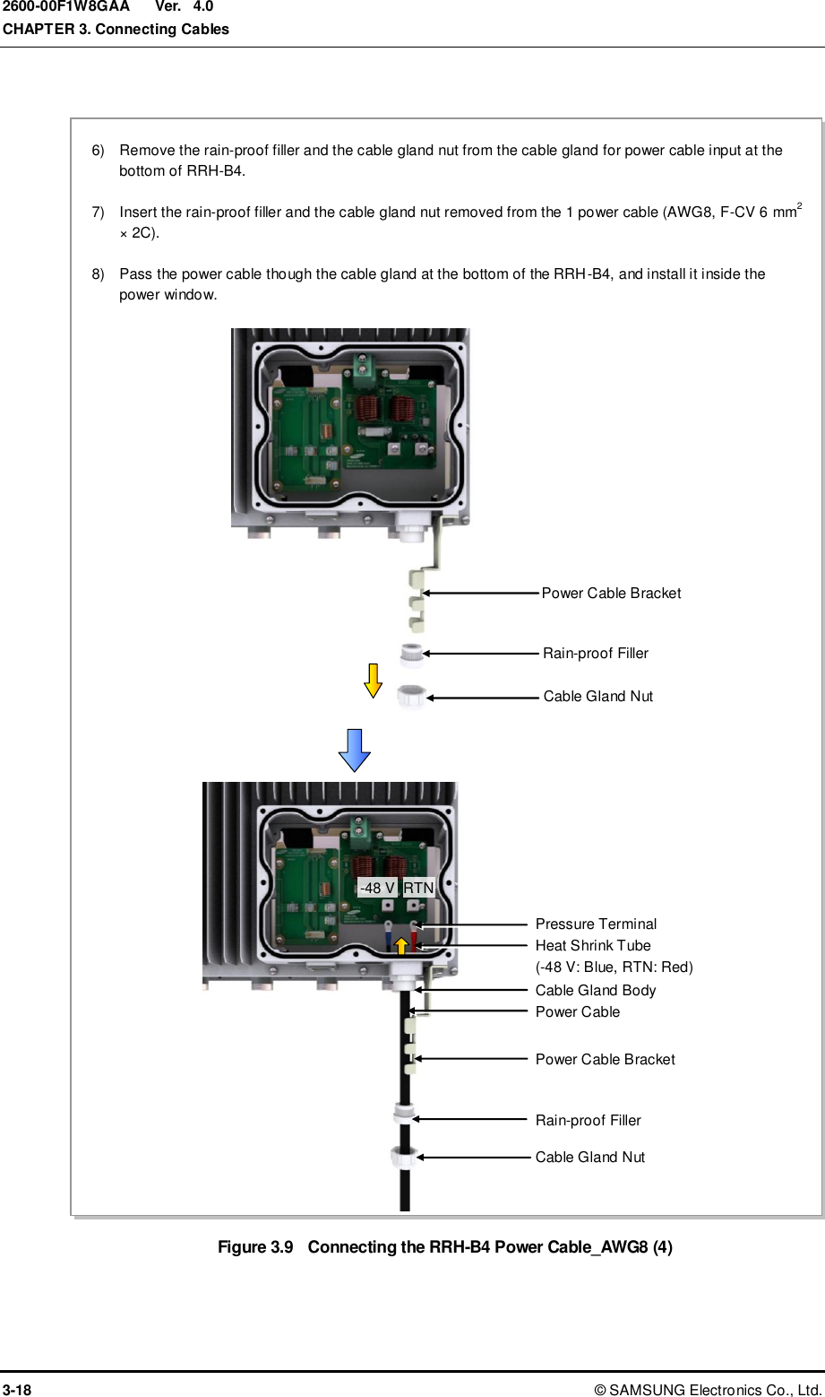
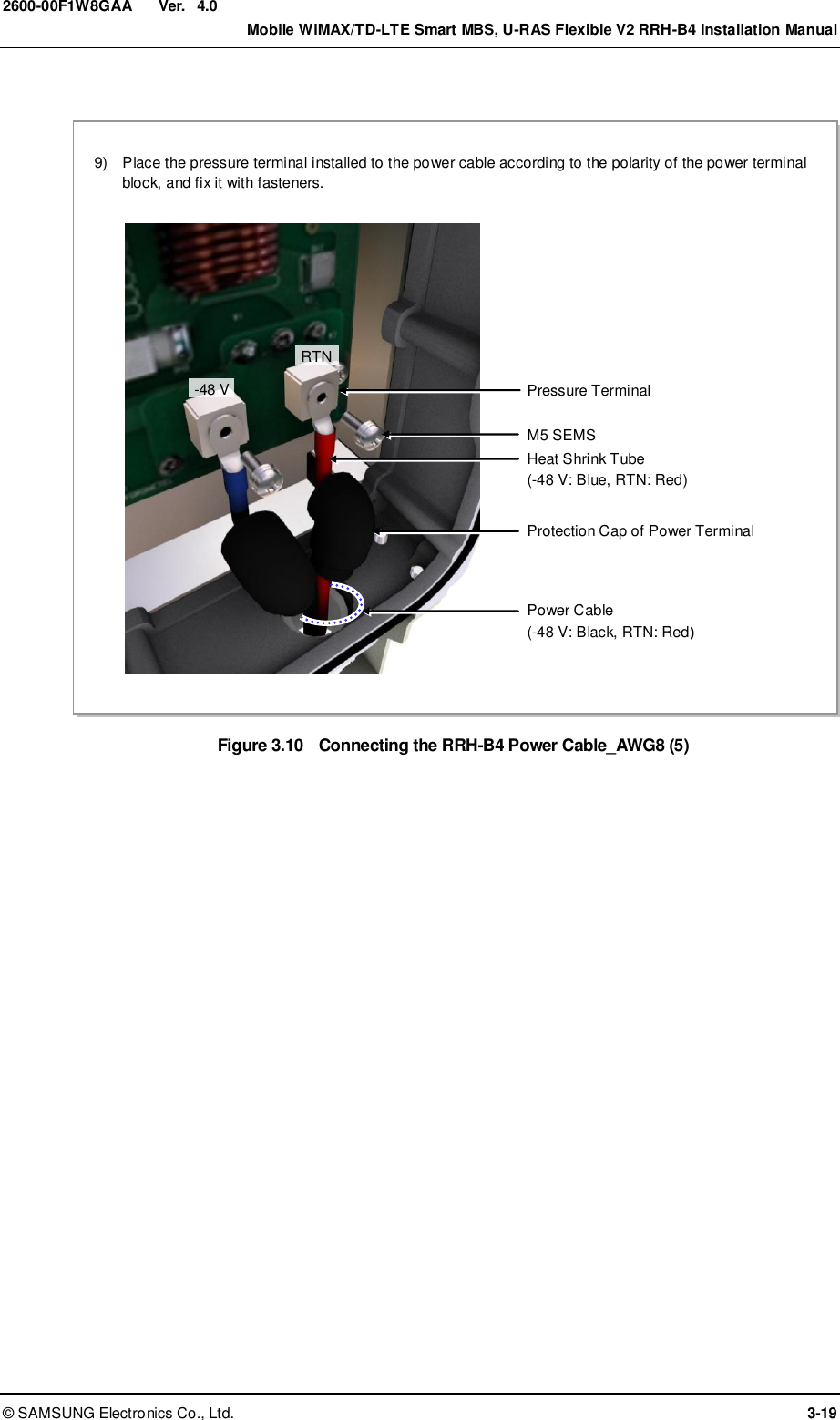
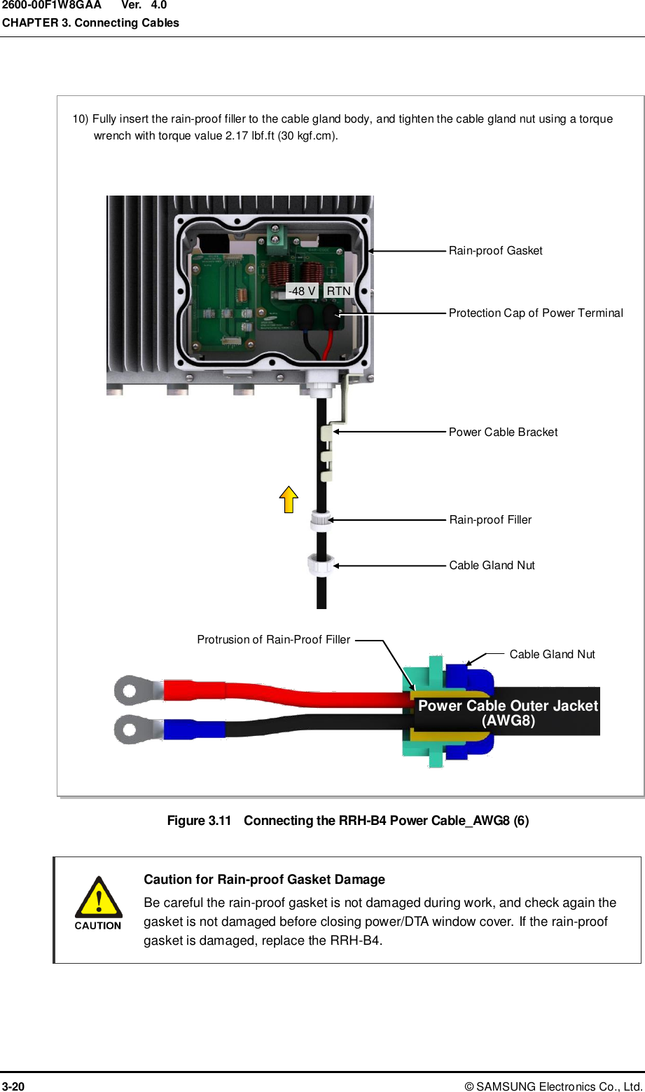
![Ver. CHAPTER 3. Connecting Cables 3-6 © SAMSUNG Electronics Co., Ltd. 2600-00F1W8GAA 4.0 3.2 Cabling The cabling diagram of the RRH-B4 is as follows: Figure 3.3 Cabling Diagram 3) RRH-B4 Ground Cable [RF Antenna] [MGB] 2) TGB Ground Cable [TGB] Feeder Line Ground Cable (When Using Ground Kit/7/8 in. Feeder Line) ※ TGB and Ground Kit are used when using the 7/8 in. feeder line or more. [Rectifier] [Smart MBS UADU] 4) Power Cable 1) MGB Ground Cable 5) CPRI Cable 6) RET Cable 7) RF Cable [U-RAS Flexible V2 DU]](https://usermanual.wiki/Samsung-Electronics-Co/SLS-BD106Q.User-Manual-1/User-Guide-1865351-Page-54.png)
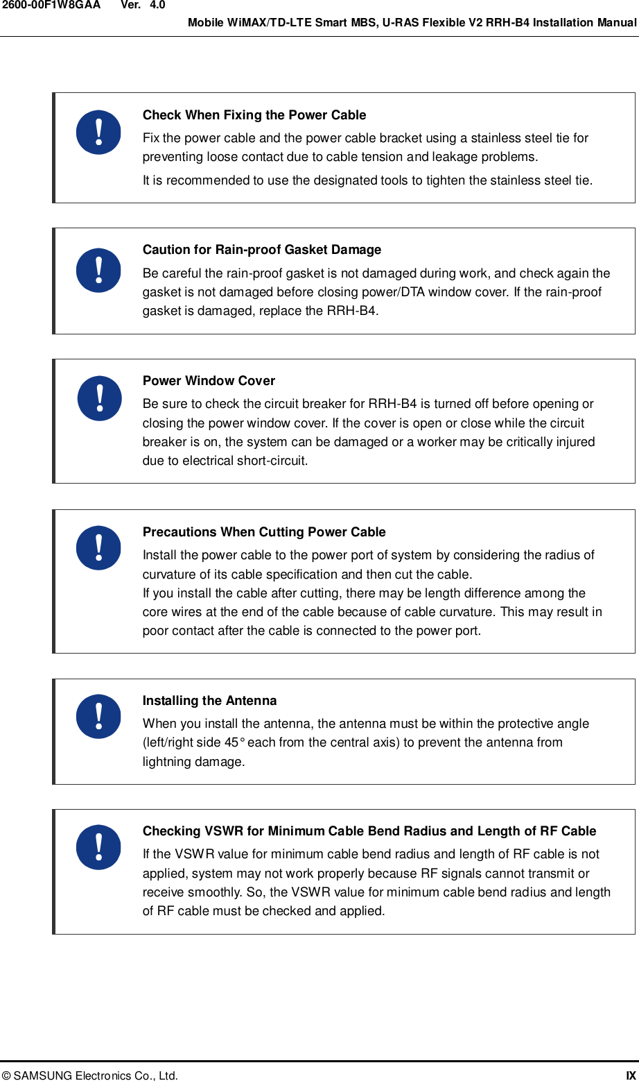
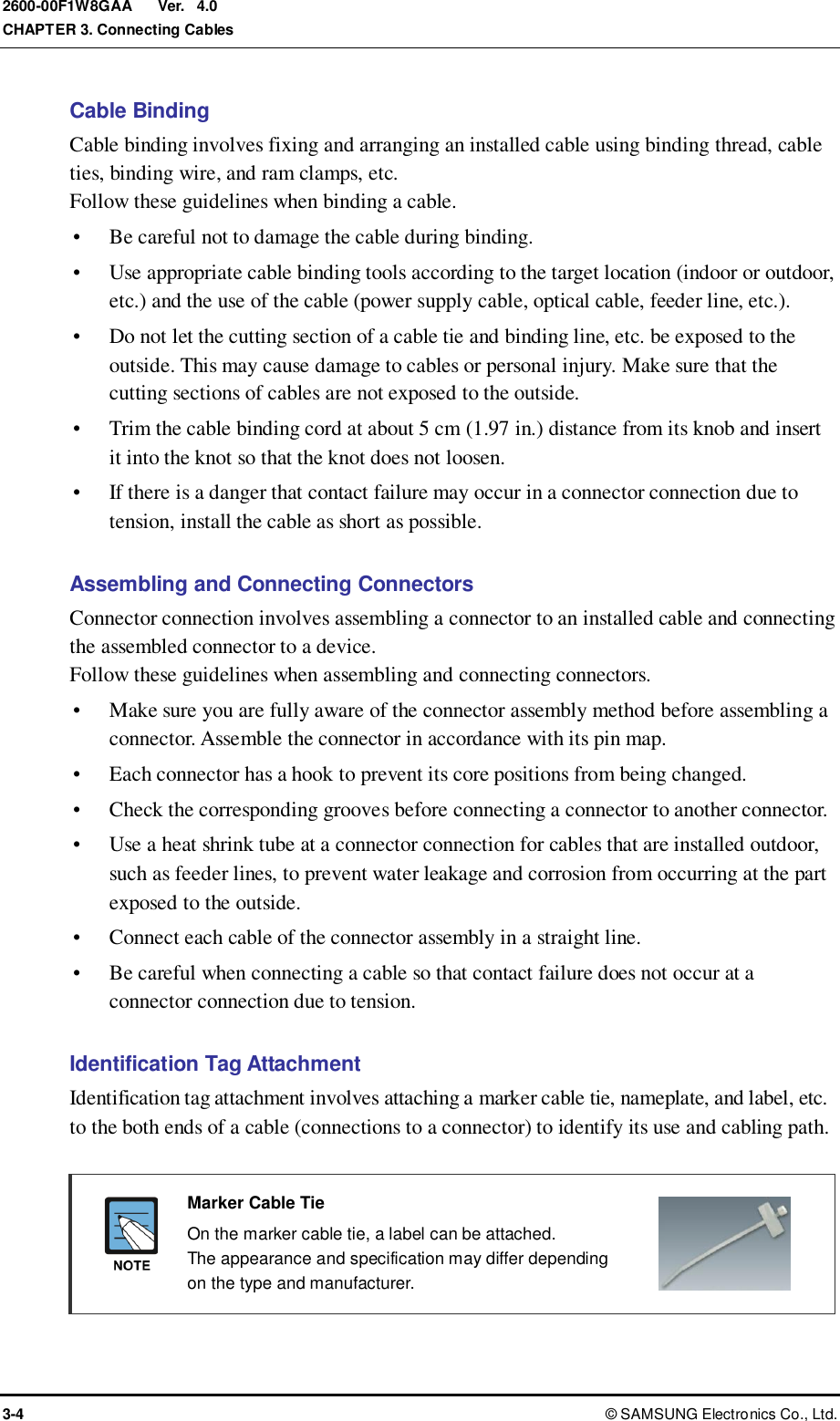
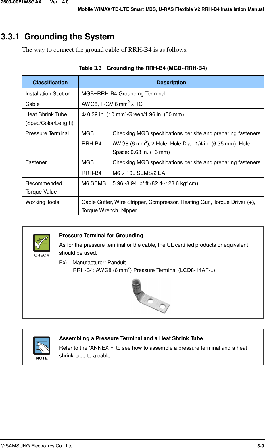
![Ver. CHAPTER 3. Connecting Cables 3-8 © SAMSUNG Electronics Co., Ltd. 2600-00F1W8GAA 4.0 3.3 Grounding Grounding is required for protecting complex electronic or electric systems such as power system, communication system, and control system from lightning, over-current, over-voltage, and electric noise. Thus, the systems can operate properly and protect human life from electrical shock. Ground equipment minimizes the electrical potential of the electronic device to that of the ground, which is zero electrical potential, so that it can prevent the device from occurring electrification. The purposes of the ground construction are as follows: To prevent human life and the system from over-current, over-voltage, and lightning To provide a discharge path for surge voltage generated by lightning and power switch To protect the system from static electricity To eliminate or minimize the high-frequency potential in the system housing To provide a conductor for the balance and stability of high-frequency current To stabilize the potential of the circuit against the ground Connecting Ground Cable In cabling, the connection of cables without the connection to the ground cable may cause the damage of the equipment or the bodily injury of the worker. Connect the ground cable first. System Grounding Method Ground bar for lightning protector/power/communication must be isolated from each other. These three ground bars can be grounded as the isolation grounding method, or branched from ground mesh buried in the underground as common grounding method. Ground Bar for Communication Ground Bar for Power Ground Bar for Lightning Protector Ground Bar for Communication Ground Bar for Power Ground Bar for Lightning Protector Underground [Isolation Grounding] [Common Grounding] Underground](https://usermanual.wiki/Samsung-Electronics-Co/SLS-BD106Q.User-Manual-1/User-Guide-1865351-Page-56.png)
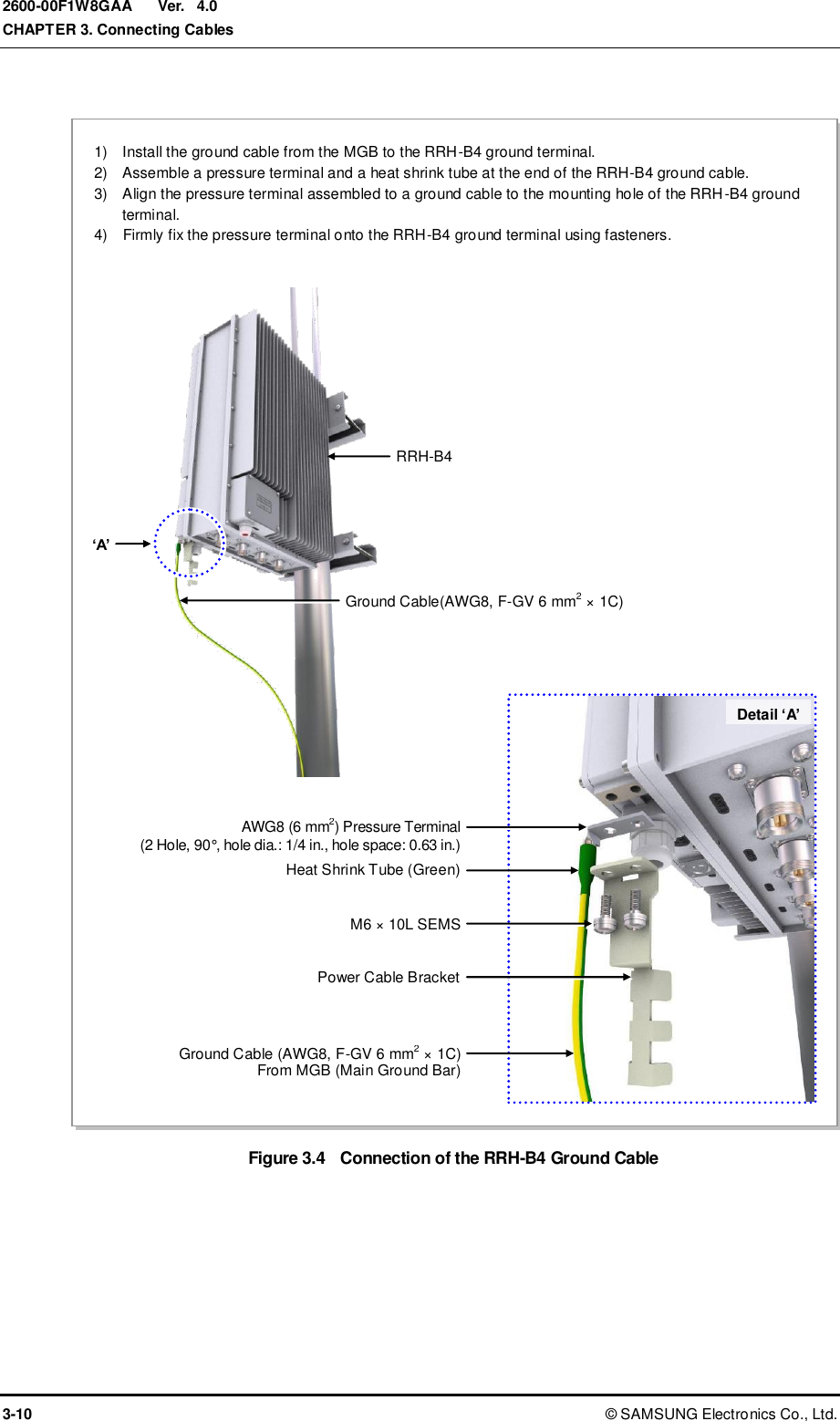

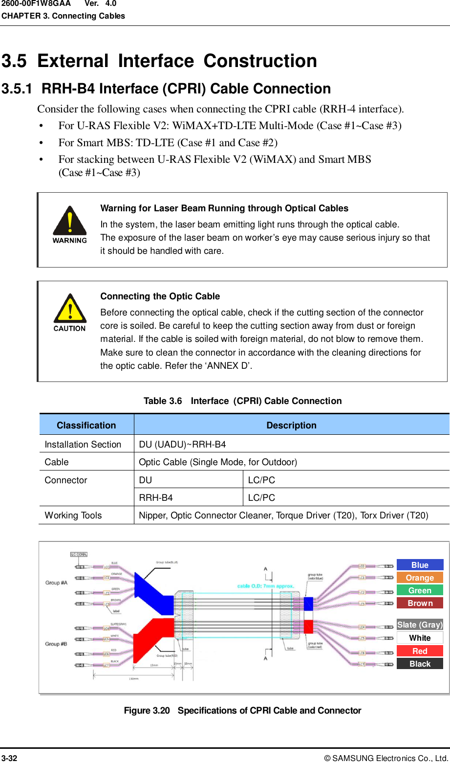
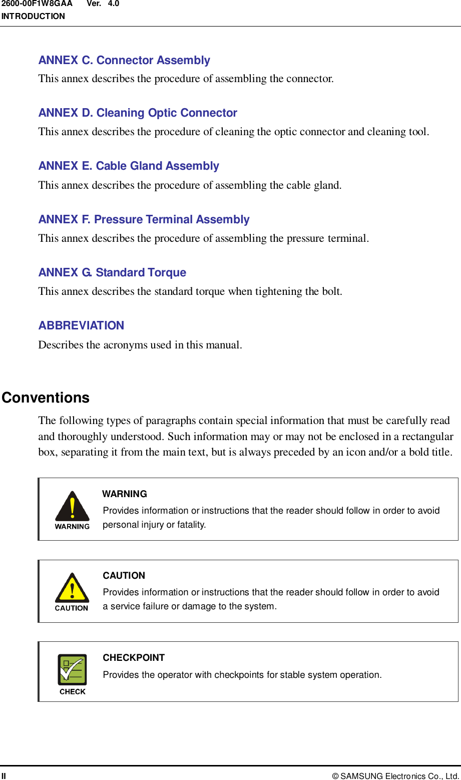
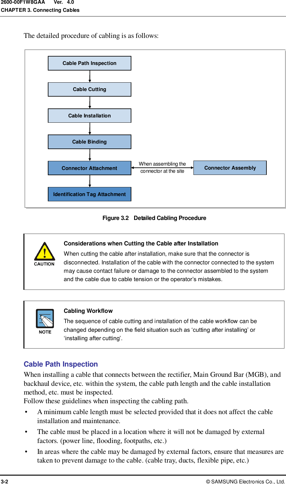
![Ver. CHAPTER 3. Connecting Cables 3-38 © SAMSUNG Electronics Co., Ltd. 2600-00F1W8GAA 4.0 3.5.1.1 For U-RAS Flexible V2: WiMAX + TD-LTE Multi-Mode Consider the following cases when connecting the CPRI cable (RRH-4 interface) for WiMAX + TD-LTE multi-mode. Case #1: WiMAX+TD-LTE, 2Tx/2Rx Follow the steps below to connect CPRI cables for 2Tx/2Rx configuration of the U-RAS Flexible V2. Table 3.7 CPRI Cable Connector Pin Map (U-RAS Flexible V2, Case #1) DU Port Optic Cable Color (Cable Marker) RRH-B4 MRA-F #0 L0 Slate[Gray] (LC4) RRH-B4 #0 L1 - MRA-F #1 L0 Slate[Gray] (LC4) RRH-B4 #1 L1 - MRA-F #2 L0 Slate[Gray] (LC4) RRH-B4 #2 L1 - MRA-F #3 L0 White (LC5) RRH-B4 #0 or #1 or #2 L1 - MRA-L A0 Blue (LC0) RRH-B4 #0 A1 - A2 NC A3 NC B0 Blue (LC0) RRH-B4 #1 B1 - B2 NC B3 NC C0 Blue (LC0) RRH-B4 #2 C1 - C2 NC C3 NC](https://usermanual.wiki/Samsung-Electronics-Co/SLS-BD106Q.User-Manual-1/User-Guide-1865351-Page-86.png)
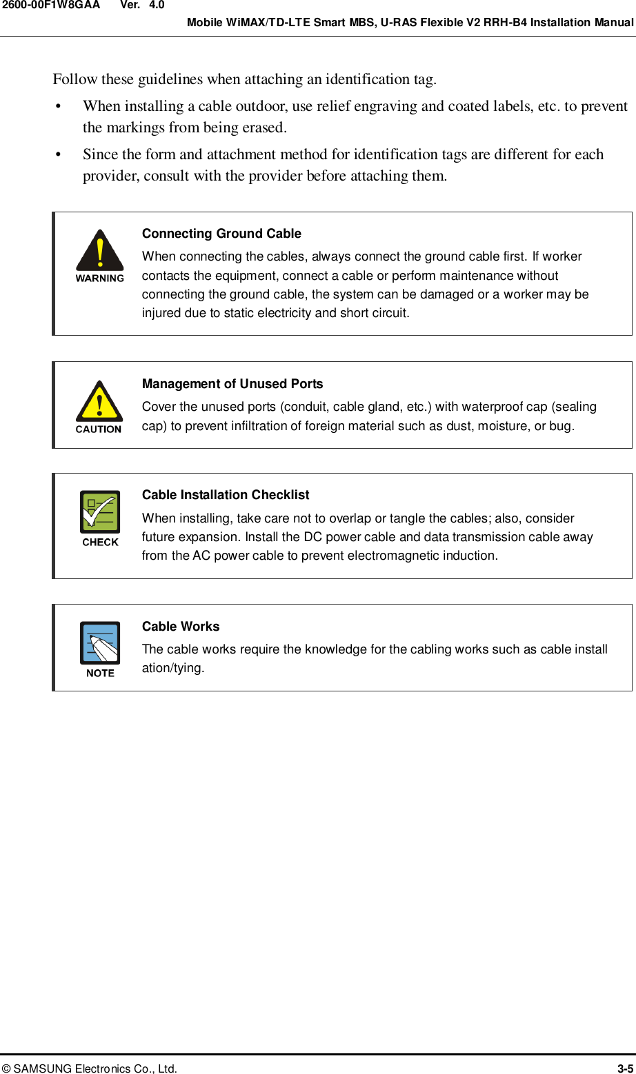
![Ver. Mobile WiMAX/TD-LTE Smart MBS, U-RAS Flexible V2 RRH-B4 Installation Manual © SAMSUNG Electronics Co., Ltd. 3-39 2600-00F1W8GAA 4.0 Figure 3.26 CPRI Cable Pin Map (U-RAS Flexible V2, Case #1) [U-RAS Flexible V2 DU] Optic0 (LTE0) Optic1 (LTE1) Optic2 (LTE2) Optic3 (LTE3) [RRH-B4 #0~#2] RRH-B4 #0 or #1 or #2 MRA-L MRA-F #3 MRA-F #2 MRA-F #1 MRA-F #0 Optic4 (WiMAX0) Optic6 (WiMAX2) Optic5 (WiMAX1) Optic7 (WiMAX3) L0 L0 L1 L0 L1 L0 L1 L1 A0 A1 A2 A3 B0 B1 B2 B3 C0 C1 C2 C3](https://usermanual.wiki/Samsung-Electronics-Co/SLS-BD106Q.User-Manual-1/User-Guide-1865351-Page-87.png)
![Ver. CHAPTER 3. Connecting Cables 3-40 © SAMSUNG Electronics Co., Ltd. 2600-00F1W8GAA 4.0 Figure 3.27 CPRI Cable Connection_U-RAS Flexible V2, Case #1 (1) 1) Install the CPRI cable (RRH-B4 interface) from the U-RAS Flexible V2 DU to the optic port on RRH-B4. 2) Connect RRH-B4 side connector of CPRI cable to the optic port. ‘A’ ‘A’ [RRH-B4 #0] [U-RAS Flexible V2 DU Front] [RRH-B4 #1] [U-RAS Flexible V2 DU Front] ‘A’ [RRH-B4 #2] [U-RAS Flexible V2 DU Front] CPRI Cable CPRI Cable CPRI Cable Optic4 (WiMAX0) Optic6 (WiMAX2) Optic5 (WiMAX1) Optic7 (WiMAX3) Optic4 (WiMAX0) Optic6 (WiMAX2) Optic5 (WiMAX1) Optic4 (WiMAX0) Optic6 (WiMAX2) Optic5 (WiMAX1) Optic7 (WiMAX3) Optic7 (WiMAX3) Optic0 (LTE0) Optic1 (LTE1) Optic3 (LTE3) Optic2 (LTE2) Optic0 (LTE0) Optic1 (LTE1) Optic2 (LTE2) Optic3 (LTE3) Optic0 (LTE0) Optic1 (LTE1) Optic2 (LTE2) Optic3 (LTE3)](https://usermanual.wiki/Samsung-Electronics-Co/SLS-BD106Q.User-Manual-1/User-Guide-1865351-Page-88.png)
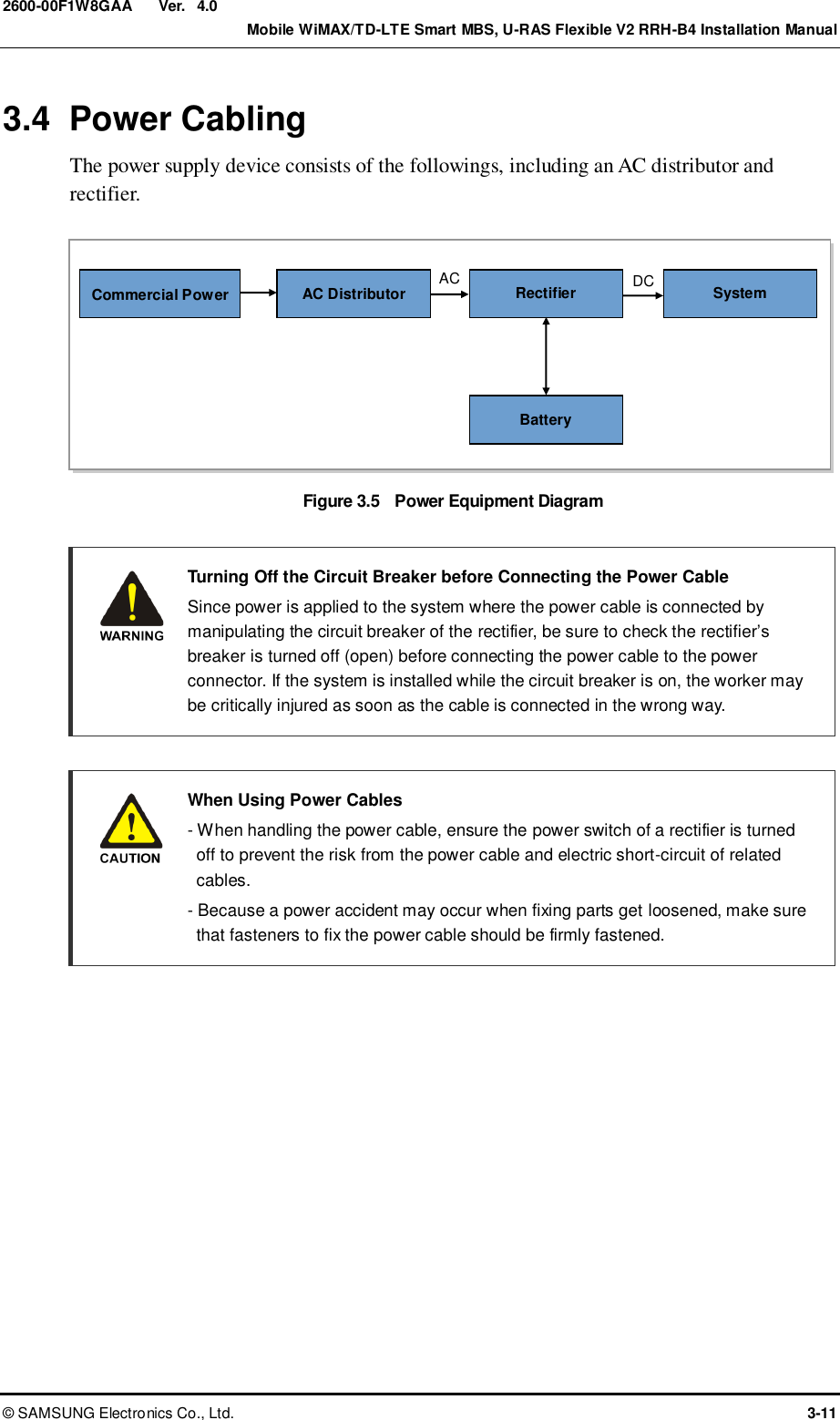
![Ver. CHAPTER 3. Connecting Cables 3-42 © SAMSUNG Electronics Co., Ltd. 2600-00F1W8GAA 4.0 Case #2: WiMAX 4 Subcells+TD-LTE 1 Carrier/3 Sector, 2Tx/2Rx Follow the steps below to connect CPRI cables for WiMAX 4 subcells + TD-LTE 1 Carrier/3 Sector 2Tx/2Rx configuration of U-RAS Flexible V2. When U-RAS Flexible V2 supports WiMAX/TD-LTE multi-mode, up to 4 WiMAX channel cards (MRA-F) can be mounted on the U-RAS Flexible V2 to support 4 subcells. The operator can set operating sectors and frequencies for each subcell. The following example shows the pin map where an alpha sector has 3 and a beta sector has 1 respectively among 6 WiMAX subcells. Table 3.8 CPRI Cable Connector Pin Map (U-RAS Flexible V2, Case #2) DU Port Optic Cable Color (Cable Marker) RRH-B4 MRA-F #0 L0 Slate[Gray] (LC4) RRH-B4 #0 L1 - MRA-F #1 L0 White (LC5) RRH-B4 #0 L1 - MRA-F #2 L0 Red (LC6) RRH-B4 #0 L1 - MRA-F #3 L0 Slate[Gray] (LC4) RRH-B4 #1 L1 - MRA-L A0 Blue (LC0) RRH-B4 #0 A1 - A2 NC A3 NC B0 Blue (LC0) RRH-B4 #1 B1 - B2 NC B3 NC C0 Blue (LC0) RRH-B4 #2 C1 - C2 NC C3 NC](https://usermanual.wiki/Samsung-Electronics-Co/SLS-BD106Q.User-Manual-1/User-Guide-1865351-Page-90.png)
![Ver. Mobile WiMAX/TD-LTE Smart MBS, U-RAS Flexible V2 RRH-B4 Installation Manual © SAMSUNG Electronics Co., Ltd. 3-43 2600-00F1W8GAA 4.0 Figure 3.29 CPRI Cable Pin Map (U-RAS Flexible V2, Case #2) Optic0 (LTE0) Optic1 (LTE1) Optic2 (LTE2) Optic3 (LTE3) Optic4 (WiMAX0) Optic6 (WiMAX2) Optic5 (WiMAX1) Optic7 (WiMAX3) Optic0 (LTE0) Optic1 (LTE1) Optic2 (LTE2) Optic3 (LTE3) Optic4(WiMAX0) Optic6(WiMAX2) Optic5(WiMAX1) Optic7(WiMAX3) MRA-L MRA-F #3 MRA-F #2 MRA-F #1 MRA-F #0 L0 L0 L1 L1 L0 L1 L1 A0 A1 A2 A3 B0 B1 B2 B3 Power Cable Bracket C0 C1 C2 C3 [U-RAS Flexible V2 DU] [RRH-B4 #0] [RRH-B4 #1] [RRH-B4 #2] L0 Optic0 (LTE0) Optic1 (LTE1) Optic2 (LTE2) Optic3 (LTE3) Optic4 (WiMAX0) Optic6 (WiMAX2) Optic5 (WiMAX1) Optic7 (WiMAX3)](https://usermanual.wiki/Samsung-Electronics-Co/SLS-BD106Q.User-Manual-1/User-Guide-1865351-Page-91.png)
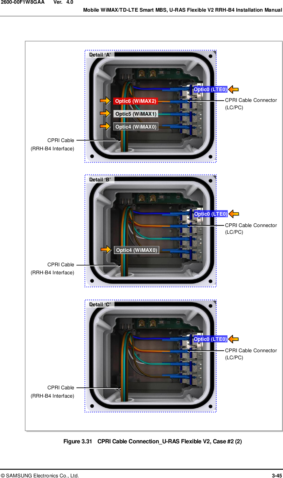
![Ver. CHAPTER 3. Connecting Cables 3-44 © SAMSUNG Electronics Co., Ltd. 2600-00F1W8GAA 4.0 Figure 3.30 CPRI Cable Connection_U-RAS Flexible V2, Case #2 (1) Optic0 (LTE0) Optic1 (LTE1) Optic2 (LTE2) Optic3 (LTE3) Optic0 (LTE0) Optic1 (LTE1) Optic2 (LTE2) Optic3 (LTE3) Optic0 (LTE0) Optic1 (LTE1) Optic2(LTE2) Optic3 (LTE3) ‘B’ ‘A’ [RRH-B4 #0] 1) Install the CPRI cable (RRH-B4 interface) from the U-RAS Flexible V2 DU to the optic port on RRH-B4. 2) Connect RRH-B4 side connector of CPRI cable to the optic port. [U-RAS Flexible V2 DU Front] [RRH-B4 #1] [U-RAS Flexible V2 DU Front] ‘C’ [U-RAS Flexible V2 DU Front] Optic4 (WiMAX0) Optic6 (WiMAX2) Optic5 (WiMAX1) Optic7 (WiMAX3) Optic4 (WiMAX0) Optic6 (WiMAX2) Optic5 (WiMAX1) Optic7 (WiMAX3) Optic4 (WiMAX0) Optic6 (WiMAX2) Optic5 (WiMAX1) Optic7 (WiMAX3)](https://usermanual.wiki/Samsung-Electronics-Co/SLS-BD106Q.User-Manual-1/User-Guide-1865351-Page-92.png)
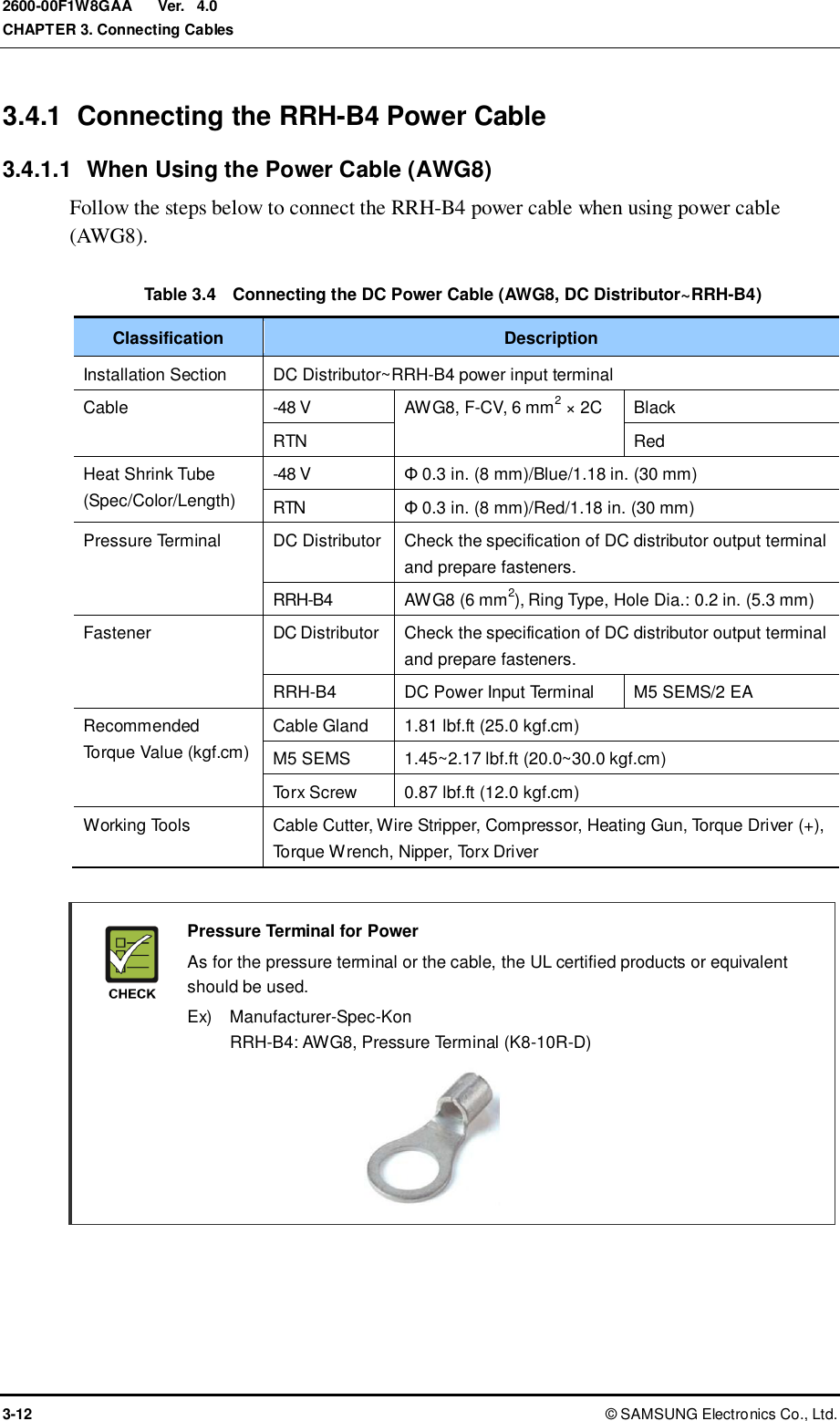
![Ver. CHAPTER 3. Connecting Cables 3-46 © SAMSUNG Electronics Co., Ltd. 2600-00F1W8GAA 4.0 Case #3: 2Tx/4Rx or 4Tx/4Rx Follow the steps below to connect CPRI cables for 2Tx/4Rx or 4Tx/4Rx configuration of the U-RAS Flexible V2. Table 3.9 CPRI Cable Connector Pin Map (U-RAS Flexible V2, Case #3) DU Port Optic Cable Color (Cable Marker) RRH-B4 MRA-F #0 L0 Slate[Gray] (LC4) RRH-B4 #0 L1 Red (LC6) MRA-F #1 L0 Slate[Gray] (LC4) RRH-B4 #1 L1 Red (LC6) MRA-F #2 L0 Slate[Gray] (LC4) RRH-B4 #2 L1 Red (LC6) MRA-F #3 L0 White (LC5) RRH-B4 #0 or #1 or #2 L1 Black (LC7) MRA-L A0 Blue (LC0) RRH-B4 #0 A1 Green (LC1) A2 NC A3 NC B0 Blue (LC0) RRH-B4 #1 B1 Green (LC1) B2 NC B3 NC C0 Blue (LC0) RRH-B4 #2 C1 Green (LC1) C2 NC C3 NC](https://usermanual.wiki/Samsung-Electronics-Co/SLS-BD106Q.User-Manual-1/User-Guide-1865351-Page-94.png)
![Ver. Mobile WiMAX/TD-LTE Smart MBS, U-RAS Flexible V2 RRH-B4 Installation Manual © SAMSUNG Electronics Co., Ltd. 3-47 2600-00F1W8GAA 4.0 Figure 3.32 CPRI Cable Pin Map (U-RAS Flexible V2, Case #3) [U-RAS Flexible V2 DU] Optic0 (LTE0) Optic1 (LTE1) Optic2 (LTE2) Optic3 (LTE3) [RRH-B4 #0~#2] RRH-B4 #0 or #1 or #2 MRA-L MRA-F #3 MRA-F #2 MRA-F #1 MRA-F #0 Optic4 (WiMAX0) Optic6 (WiMAX2) Optic5 (WiMAX1) Optic7 (WiMAX3) L0 L0 L1 L0 L1 L0 L1 L1 A0 A1 A2 A3 B0 B1 B2 B3 C0 C1 C2 C3 RRH-B4 #0 or #1 or #2](https://usermanual.wiki/Samsung-Electronics-Co/SLS-BD106Q.User-Manual-1/User-Guide-1865351-Page-95.png)
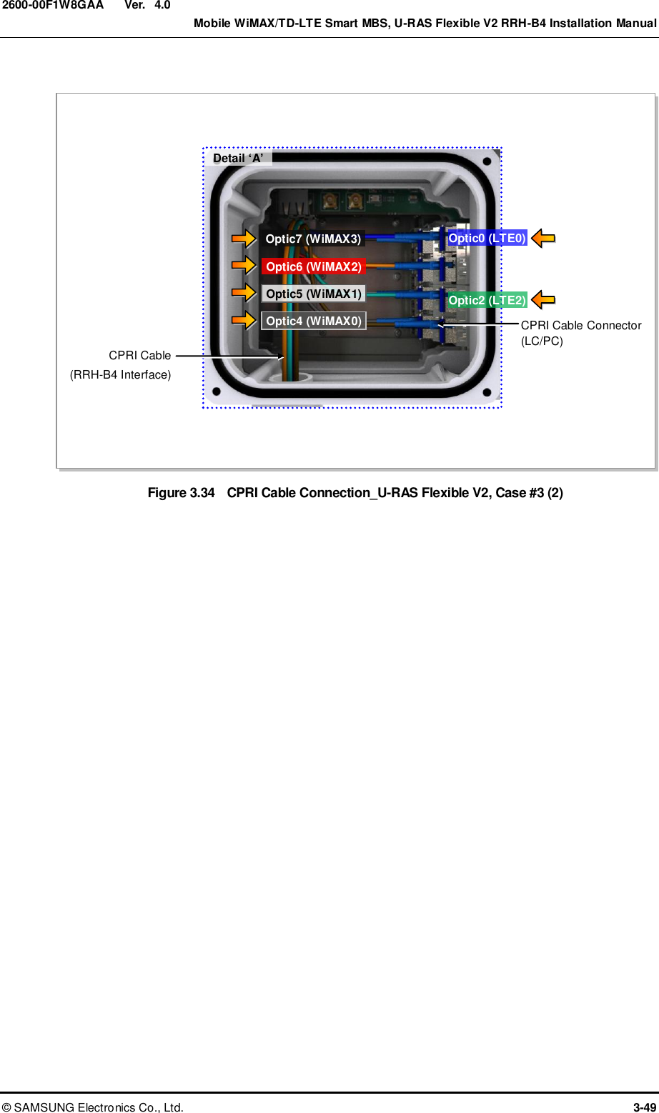
![Ver. CHAPTER 3. Connecting Cables 3-48 © SAMSUNG Electronics Co., Ltd. 2600-00F1W8GAA 4.0 Figure 3.33 CPRI Cable Connection_U-RAS Flexible V2, Case #3 (1) ‘A’ [RRH-B4 #0] 1) Install the CPRI cable (RRH-B4 interface) from the U-RAS Flexible V2 DU to the optic port on RRH-B4. 2) Connect RRH-B4 side connector of CPRI cable to the optic port. [U-RAS Flexible V2 DU Front] ‘A’ [RRH-B4 #1] [U-RAS Flexible V2 DU Front] ‘A’ [RRH-B4 #2] [U-RAS Flexible V2 DU Front] Optic4 (WiMAX0) Optic6 (WiMAX2) Optic5 (WiMAX1) Optic7 (WiMAX3) Optic4 (WiMAX0) Optic6 (WiMAX2) Optic5 (WiMAX1) Optic7 (WiMAX3) Optic4 (WiMAX0) Optic6 (WiMAX2) Optic 5(WiMAX1) Optic7 (WiMAX3) Optic0 (LTE0) Optic1 (LTE1) Optic2 (LTE2) Optic3 (LTE3) Optic0 (LTE0) Optic1 (LTE1) Optic2 (LTE2) Optic3 (LTE3) Optic0 (LTE0) Optic1 (LTE1) Optic2 (LTE2) Optic3 (LTE3)](https://usermanual.wiki/Samsung-Electronics-Co/SLS-BD106Q.User-Manual-1/User-Guide-1865351-Page-96.png)
![Ver. Mobile WiMAX/TD-LTE Smart MBS, U-RAS Flexible V2 RRH-B4 Installation Manual © SAMSUNG Electronics Co., Ltd. 3-51 2600-00F1W8GAA 4.0 Figure 3.35 CPRI Cable Pin Map (Smart MBS, Case #1) L0 L9CA #0 L2 L4 [UADU] L0 L2 L4 Optic0 (LTE0) Optic1 (LTE1) Optic2 (LTE2) Optic3 (LTE3) Optic4 (WiMAX0) Optic6 (WiMAX2) Optic5 (WiMAX1) Optic7 (WiMAX3) [RRH-B4 #0~#2] L1 L3 L5 L1 L3 L5 L9CA #1](https://usermanual.wiki/Samsung-Electronics-Co/SLS-BD106Q.User-Manual-1/User-Guide-1865351-Page-99.png)
![Ver. CHAPTER 3. Connecting Cables 3-52 © SAMSUNG Electronics Co., Ltd. 2600-00F1W8GAA 4.0 Figure 3.36 CPRI Cable Connection_Smart MBS, Case #1 (1) Optic4 (WiMAX0) Optic6 (WiMAX2) Optic5 (WiMAX1) Optic7 (WiMAX3) ‘A’ [RRH-B4 #0] Optic4 (WiMAX0) Optic6 (WiMAX2) Optic5 (WiMAX1) Optic7 (WiMAX3) 1) Install the CPRI cable (RRH-B4 interface) from the Smart MBS UADU to the optic port on RRH-B4. 2) Connect RRH-B4 side connector of CPRI cable to the optic port. [UADU] ‘A’ CPRI Cable CPRI Cable [UADU] [RRH-B4 #1] Optic0 (LTE0) Optic1 (LTE1) Optic2 (LTE2) Optic3 (LTE3) Optic0 (LTE0) Optic1 (LTE1) Optic2 (LTE2) Optic3 (LTE3)](https://usermanual.wiki/Samsung-Electronics-Co/SLS-BD106Q.User-Manual-1/User-Guide-1865351-Page-100.png)
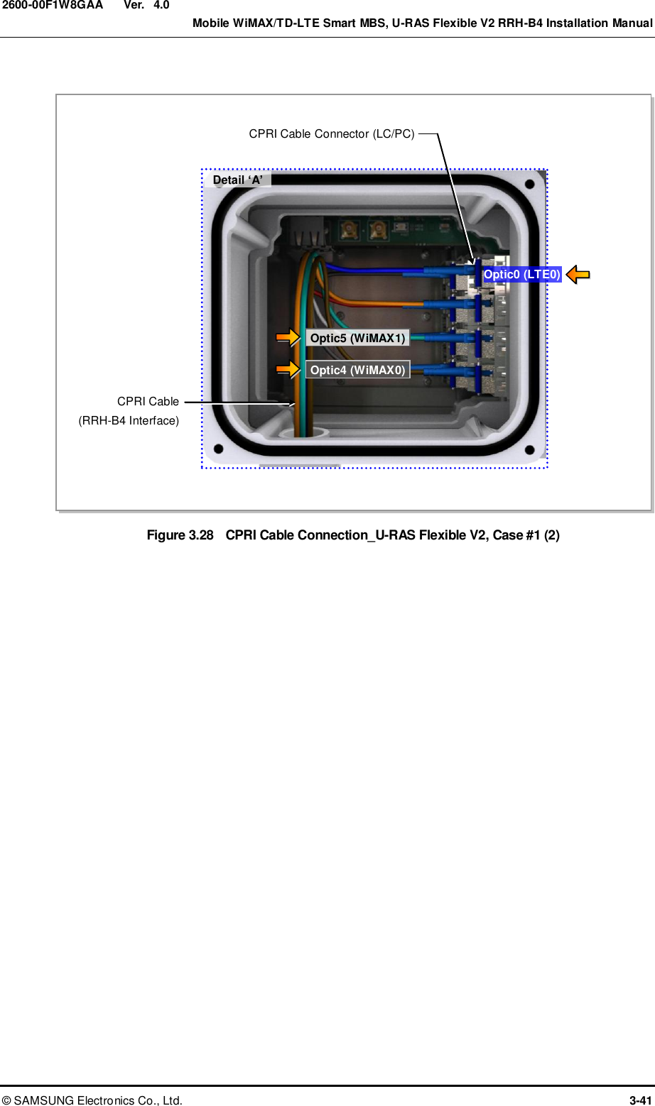
![Ver. Mobile WiMAX/TD-LTE Smart MBS, U-RAS Flexible V2 RRH-B4 Installation Manual © SAMSUNG Electronics Co., Ltd. 3-53 2600-00F1W8GAA 4.0 Figure 3.37 CPRI Cable Connection_Smart MBS, Case #1 (2) Optic4 (WiMAX0) Optic6 (WiMAX2) Optic5 (WiMAX1) Optic7 (WiMAX3) ‘A’ [UADU] CPRI Cable [RRH-B4 #2] Detail ‘A’ CPRI Cable (RRH-B4 Interface) CPRI Cable Connector (LC/PC) Optic0 (LTE0) Optic1 (LTE1) Optic0 (LTE0) Optic1 (LTE1) Optic2 (LTE2) Optic3 (LTE3)](https://usermanual.wiki/Samsung-Electronics-Co/SLS-BD106Q.User-Manual-1/User-Guide-1865351-Page-101.png)
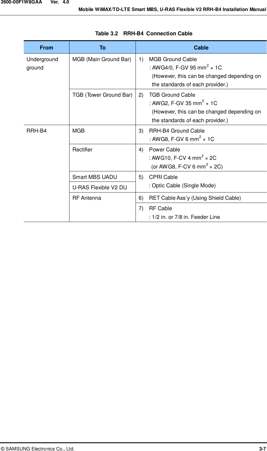
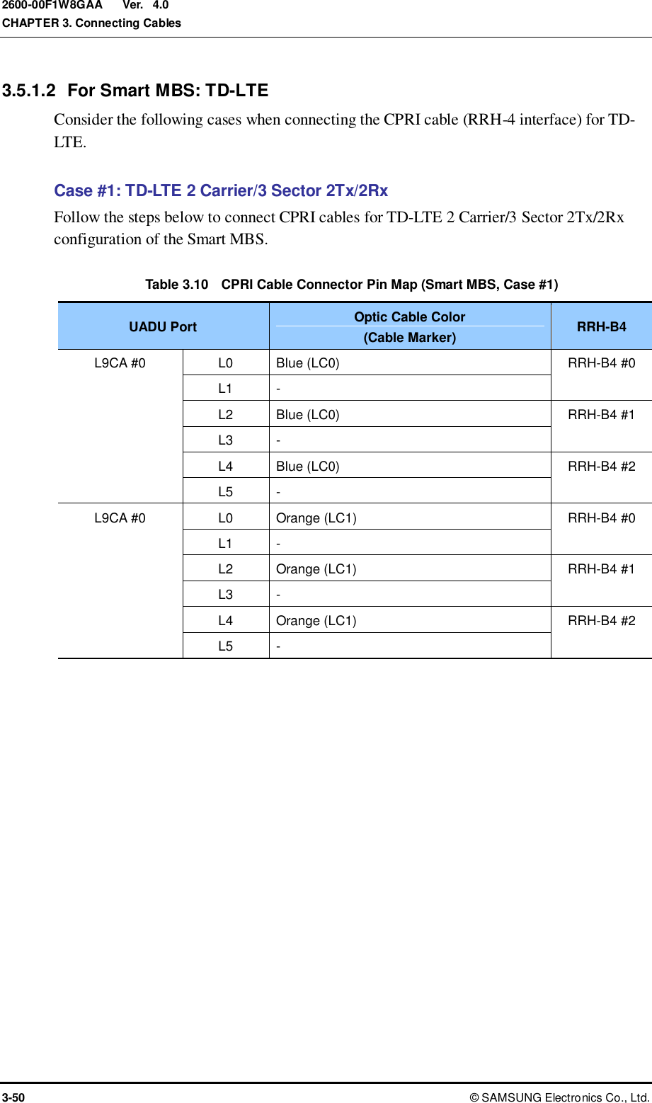
![Ver. CHAPTER 3. Connecting Cables 3-54 © SAMSUNG Electronics Co., Ltd. 2600-00F1W8GAA 4.0 Case #2: TD-LTE 2 Carrier/3 Sector 2Tx/4Rx or 4Tx/4Rx Follow the steps below to connect CPRI cables for TD-LTE 2 Carrier/3 Sector 2Tx/4Rx or 4Tx/4Rx configuration of the Smart MBS. Table 3.11 CPRI Cable Connector Pin Map (Smart MBS, Case #2) UADU Port Optic Cable Color (Cable Marker) RRH-B4 L9CA #0 L0 Blue (LC0) RRH-B4 #0 L1 Green (LC2) L2 Blue (LC0) RRH-B4 #1 L3 Green (LC2) L4 Blue (LC0) RRH-B4 #2 L5 Green (LC2) L9CA #1 L0 Orange (LC1) RRH-B4 #0 L1 Brown (LC3) L2 Orange (LC1) RRH-B4 #1 L3 Brown (LC3) L4 Orange (LC1) RRH-B4 #2 L5 Brown (LC3) Figure 3.38 CPRI Cable Pin Map (Smart MBS, Case #2) Optic0 (LTE0) Optic1 (LTE1) Optic2 (LTE2) Optic3 (LTE3) [RRH-B4 #0~2] L0 L9CA #1 L9CA #0 L2 L4 L1 L3 L5 [UADU] L0 L2 L4 L1 L3 L5 Optic4 (WiMAX0) Optic6 (WiMAX2) Optic5 (WiMAX1) Optic7 (WiMAX3)](https://usermanual.wiki/Samsung-Electronics-Co/SLS-BD106Q.User-Manual-1/User-Guide-1865351-Page-102.png)
![Ver. Mobile WiMAX/TD-LTE Smart MBS, U-RAS Flexible V2 RRH-B4 Installation Manual © SAMSUNG Electronics Co., Ltd. 3-55 2600-00F1W8GAA 4.0 Figure 3.39 CPRI Cable Connection_Smart MBS, Case #2 (1) Optic4 (WiMAX0) Optic6 (WiMAX2) Optic5 (WiMAX1) Optic7 (WiMAX3) ‘A’ [RRH-B4 #0] Optic4 (WiMAX0) Optic6 (WiMAX2) Optic5 (WiMAX1) Optic7 (WiMAX3) 1) Install the CPRI cable (RRH-B4 interface) from the Smart MBS UADU to the optic port on RRH-B4. 2) Connect RRH-B4 side connector of CPRI cable to the optic port. ‘A’ [RRH-B4 #1] [UADU] CPRI Cable [UADU] CPRI Cable Optic0 (LTE0) Optic1 (LTE1) Optic2 (LTE2) Optic3 (LTE3) Optic0 (LTE0) Optic1 (LTE1) Optic2 (LTE2) Optic3 (LTE3)](https://usermanual.wiki/Samsung-Electronics-Co/SLS-BD106Q.User-Manual-1/User-Guide-1865351-Page-103.png)
![Ver. CHAPTER 3. Connecting Cables 3-56 © SAMSUNG Electronics Co., Ltd. 2600-00F1W8GAA 4.0 Figure 3.40 CPRI Cable Connection_Smart MBS, Case #2 (2) Optic4 (WiMAX0) Optic6 (WiMAX2) Optic5 (WiMAX1) Optic7 (WiMAX3) ‘A’ [RRH-B4 #2] Detail ‘A’ CPRI Cable (RRH-B4 Interface) CPRI Cable Connector (LC/PC) Optic0 (LTE0) Optic1 (LTE1) CPRI Cable [UADU] Optic3 (LTE3) Optic1 (LTE2) Optic0 (LTE0) Optic1 (LTE1) Optic2 (LTE2) Optic3 (LTE3)](https://usermanual.wiki/Samsung-Electronics-Co/SLS-BD106Q.User-Manual-1/User-Guide-1865351-Page-104.png)
![Ver. Mobile WiMAX/TD-LTE Smart MBS, U-RAS Flexible V2 RRH-B4 Installation Manual © SAMSUNG Electronics Co., Ltd. 3-57 2600-00F1W8GAA 4.0 3.5.1.3 For Stacking between U-RAS Flexible V2 (WiMAX) and Smart MBS Following shows how to connect CPRI cables for stacking between U-RAS Flexible V2 (WiMAX) and Smart MBS (TD-LTE). Case#1: WiMAX 2 Carrier/3 Sector 2Tx/2Rx+TD-LTE 2 Carrier/3 Sector 2Tx/2Rx Follow the steps below to connect CPRI cables for WiMAX 2 Carrier/3 Sector 2Tx/2Rx + TD-LTE 2 Carrier/3 Sector 2Tx/2Rx configuration of U-RAS Flexible V2 and Smart MBS. Table 3.12 CPRI Cable Connector Pin Map (Stacking, Case #1) DU (UADU) DU (UADU) Port Optic Cable Color (Cable Marker) RRH-B4 U-RAS Flexible V2 MRA-F #0 L0 Slate[Gray] (LC4) RRH-B4 #0 L1 - MRA-F #1 L0 Slate[Gray] (LC4) RRH-B4 #1 L1 - MRA-F #2 L0 Slate[Gray] (LC4) RRH-B4 #2 L1 - MRA-F #3 L0 White (LC5) RRH-B4 #0 L1 - MRA-F #4 L0 White (LC5) RRH-B4 #1 L1 - MRA-F #5 L0 White (LC5) RRH-B4 #2 L1 - Smart MBS L9CA #0 L0 Blue (LC0) RRH-B4 #0 L1 - L2 Blue (LC0) RRH-B4 #1 L3 - L4 Blue (LC0) RRH-B4 #2 L5 - L9CA #1 L0 Orange (LC1) RRH-B4 #0 L1 - L2 Orange (LC1) RRH-B4 #1 L3 - L4 Orange (LC1) RRH-B4 #2 L5 -](https://usermanual.wiki/Samsung-Electronics-Co/SLS-BD106Q.User-Manual-1/User-Guide-1865351-Page-105.png)
![Ver. CHAPTER 3. Connecting Cables 3-58 © SAMSUNG Electronics Co., Ltd. 2600-00F1W8GAA 4.0 Figure 3.41 CPRI Cable Pin Map (Stacking, Case #1) L0 L9CA #1 L9CA #0 L2 L4 Optic0 (LTE0) Optic1 LTE1) Optic2 (LTE2) Optic3 (LTE3) L1 L3 L5 [UADU] [RRH-B4 #0~#2] L0 L2 L4 L1 L3 L5 [U-RAS Flexible V2 DU] L0 L0 L0 L0 L0 L0 MRA-F #5 MRA-F #4 MRA-F #3 MRA-F #2 MRA-F #1 MRA-F #0 L1 L1 L1 L1 L1 L1 Optic4 (WiMAX0) Optic6 (WiMAX2) Optic5 (WiMAX1) Optic7 (WiMAX3)](https://usermanual.wiki/Samsung-Electronics-Co/SLS-BD106Q.User-Manual-1/User-Guide-1865351-Page-106.png)
![Ver. Mobile WiMAX/TD-LTE Smart MBS, U-RAS Flexible V2 RRH-B4 Installation Manual © SAMSUNG Electronics Co., Ltd. 3-59 2600-00F1W8GAA 4.0 Figure 3.42 CPRI Cable Connection_Stacking, Case #1 (1) 1) Install CPRI cables (RRH-B4 interface) between: - RRH-B4 and L0, L2, and L4 ports on UADU L9CA #0 and #1 - RRH-B4 and L0 ports on U-RAS Flexible V2 DU MRA-F #0-#5 2) Connect the UADU- and U-RAS Flexible V2 DU-side connectors to the following ports. - L0, L2, and L4 ports on UADU L9CA #0 and #1 - L0 ports on U-RAS Flexible V2 DU MRA-F #0-#5 CPRI Cable [RRH-B4 #0] [UADU Front] ‘A’ [RRH-B4 #1] [RRH-B4 #2] CPRI Cable CPRI Cable [U-RAS Flexible V2 DU Front] ‘B’ CPRI Cable CPRI Cable CPRI Cable](https://usermanual.wiki/Samsung-Electronics-Co/SLS-BD106Q.User-Manual-1/User-Guide-1865351-Page-107.png)
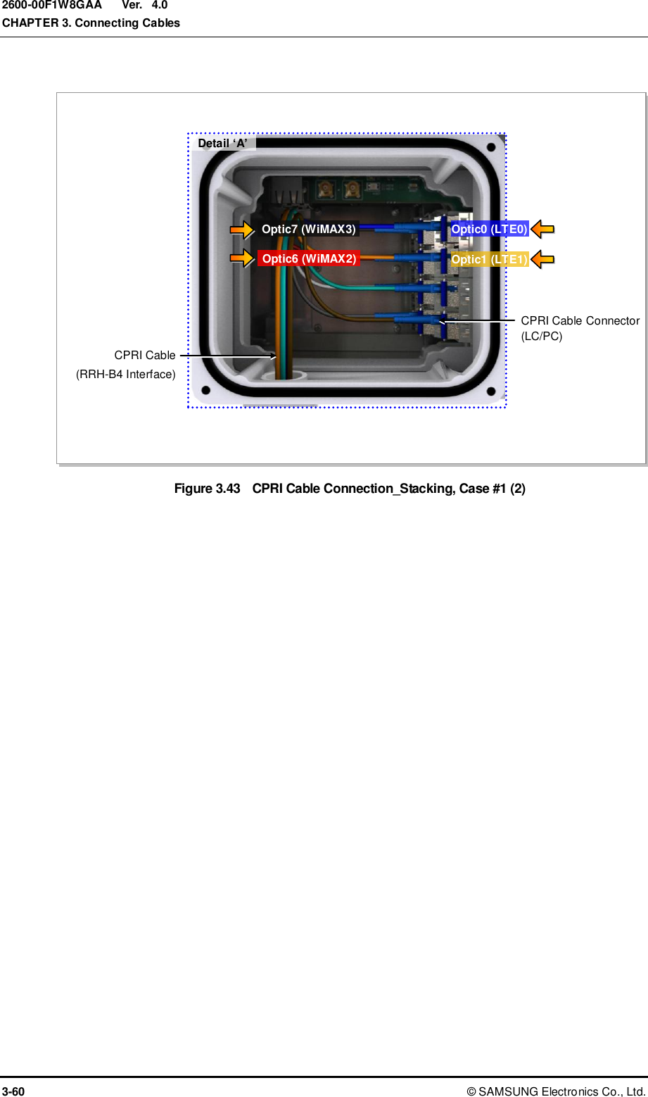
![Ver. Mobile WiMAX/TD-LTE Smart MBS, U-RAS Flexible V2 RRH-B4 Installation Manual © SAMSUNG Electronics Co., Ltd. 3-61 2600-00F1W8GAA 4.0 Case #2: WiMAX 2 Carrier/3 Sector 2Tx/4Rx + TD-LTE 2 Carrier/3 Sector 2Tx/4Rx Follow the steps below to connect CPRI cables for WiMAX 2 Carrier/3 Sector 2Tx/4Rx + TD-LTE 2 Carrier/3 Sector 2Tx/4Rx configuration of U-RAS Flexible V2 and Smart MBS. Table 3.13 CPRI Cable Connector Pin Map (Stacking, Case #2) DU (UADU) DU (UADU) Port Optic Cable Color (Cable Marker) RRH-B4 U-RAS Flexible V2 MRA-F #0 L0 Slate[Gray] (LC4) RRH-B4 #0 L1 Red (LC6) MRA-F #1 L0 Slate[Gray] (LC4) RRH-B4 #1 L1 Red (LC6) MRA-F #2 L0 Slate[Gray] (LC4) RRH-B4 #2 L1 Red (LC6) MRA-F #3 L0 White (LC5) RRH-B4 #0 L1 Black (LC7) MRA-F #4 L0 White (LC5) RRH-B4 #1 L1 Black (LC7) MRA-F #5 L0 White (LC5) RRH-B4 #2 L1 Black (LC7) Smart MBS L9CA #0 L0 Blue (LC0) RRH-B4 #0 L1 Green (LC2) L2 Blue (LC0) RRH-B4 #1 L3 Green (LC2) L4 Blue (LC0) RRH-B4 #2 L5 Green (LC2) L9CA #1 L0 Orange (LC1) RRH-B4 #0 L1 Brown (LC3) L2 Orange (LC1) RRH-B4 #1 L3 Brown (LC3) L4 Orange (LC1) RRH-B4 #2 L5 Brown (LC3)](https://usermanual.wiki/Samsung-Electronics-Co/SLS-BD106Q.User-Manual-1/User-Guide-1865351-Page-109.png)
![Ver. CHAPTER 3. Connecting Cables 3-62 © SAMSUNG Electronics Co., Ltd. 2600-00F1W8GAA 4.0 Figure 3.44 CPRI Cable Pin Map (Stacking, Case #2) L0 L9CA #1 L9CA #0 L2 L4 Optic0 (LTE0) Optic1 (LTE1) Optic2 (LTE2) Optic3 (LTE3) L1 L3 L5 [UADU] [RRH-B4 #0~#2] L0 L2 L4 L1 L3 L5 [U-RAS Flexible V2 DU] L0 L0 L0 L0 L0 L0 MRA-F #5 MRA-F #4 MRA-F #3 MRA-F #2 MRA-F #1 MRA-F #0 L1 L1 L1 L1 L1 L1 Optic4 (WiMAX0) Optic6 (WiMAX2) Optic5 (WiMAX1) Optic7 (WiMAX3)](https://usermanual.wiki/Samsung-Electronics-Co/SLS-BD106Q.User-Manual-1/User-Guide-1865351-Page-110.png)
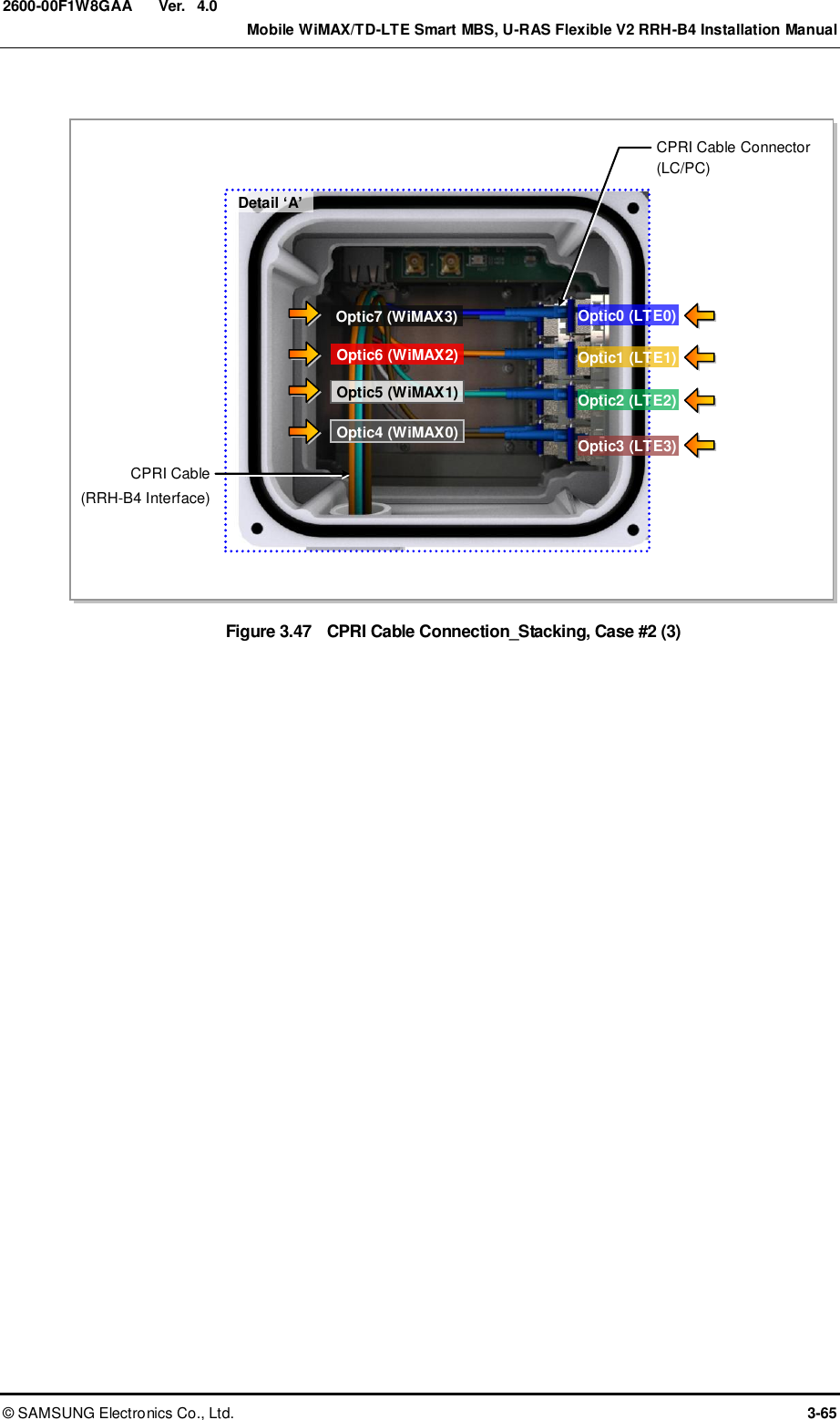
![Ver. Mobile WiMAX/TD-LTE Smart MBS, U-RAS Flexible V2 RRH-B4 Installation Manual © SAMSUNG Electronics Co., Ltd. 3-63 2600-00F1W8GAA 4.0 Figure 3.45 CPRI Cable Connection_Stacking, Case #2 (1) [U-RAS Flexible V2 DU Front] 1) Install CPRI cables (RRH-B4 interface) between: - RRH-B4 and L0~L5 ports on UADU L9CA #0 and #1 - RRH-B4 and L0 and L1 ports on U-RAS Flexible V2 DU MRA-F #0-#5 2) Connect the UADU- and U-RAS Flexible V2 DU-side connectors to the following ports. - L0~L5 ports on UADU L9CA #0 and #1 - L0 and L1 ports on U-RAS Flexible V2 DU MRA-F #0-#5 [RRH-B4 #0] [UADU Front] ‘A’ ‘B’ CPRI Cable CPRI Cable [U-RAS Flexible V2 DU Front]](https://usermanual.wiki/Samsung-Electronics-Co/SLS-BD106Q.User-Manual-1/User-Guide-1865351-Page-111.png)
![Ver. CHAPTER 3. Connecting Cables 3-64 © SAMSUNG Electronics Co., Ltd. 2600-00F1W8GAA 4.0 Figure 3.46 CPRI Cable Connection_Stacking, Case #2 (2) [UADU Front] [U-RAS Flexible V2 DU Front] [UADU Front] [U-RAS Flexible V2 DU Front] [RRH-B4 #1] ‘A’ CPRI Cable CPRI Cable ‘B’ [RRH-B4 #2] ‘A’ CPRI Cable CPRI Cable ‘B’](https://usermanual.wiki/Samsung-Electronics-Co/SLS-BD106Q.User-Manual-1/User-Guide-1865351-Page-112.png)
![Ver. CHAPTER 3. Connecting Cables 3-66 © SAMSUNG Electronics Co., Ltd. 2600-00F1W8GAA 4.0 Case #3: WiMAX 6 Subcell 2Tx/2Rx + TD-LTE 2 Carrier/3 Sector 2Tx/2Rx U-RAS Flexible V2 DU interfaces with Smart MBS to support the WiMAX and TD-LTE services simultaneously. Up to 6 WiMAX channel cards (MRA-F) can be mounted on the U-RAS Flexible V2 to support 6 subcells. The operator can set operating sectors and frequencies for each subcell. The following example shows the pin map where an alpha sector has 4 and a beta sector has 2 respectively among 6 WiMAX subcells. Table 3.14 CPRI Cable Connector Pin Map (Stacking, Case #3) DU (UADU) DU (UADU) Port Optic Cable Color (Cable Marker) RRH-B4 U-RAS Flexible V2 MRA-F #0 L0 Slate[Gray] (LC4) RRH-B4 #0 L1 - MRA-F #1 L0 White (LC5) RRH-B4 #0 L1 - MRA-F #2 L0 Red (LC6) RRH-B4 #0 L1 - MRA-F #3 L0 Black (LC7) RRH-B4 #0 L1 - MRA-F #4 L0 Slate[Gray] (LC4) RRH-B4 #1 L1 - MRA-F #5 L0 White (LC5) RRH-B4 #1 L1 - Smart MBS L9CA #0 L0 Blue (LC0) RRH-B4 #0 L1 - L2 Blue (LC0) RRH-B4 #1 L3 - L4 Blue (LC0) RRH-B4 #2 L5 - L9CA #1 L0 Orange (LC1) RRH-B4 #0 L1 - L2 Orange (LC1) RRH-B4 #1 L3 - L4 Orange (LC1) RRH-B4 #2 L5 -](https://usermanual.wiki/Samsung-Electronics-Co/SLS-BD106Q.User-Manual-1/User-Guide-1865351-Page-114.png)