Samsung Electronics Co SLS-BD106Q RRH (Remote Radio Head) User Manual 2
Samsung Electronics Co Ltd RRH (Remote Radio Head) 2
Contents
- 1. User Manual
- 2. User Manual 1
- 3. User Manual 2
User Manual 2
Ver.
Mobile WiMAX/TD-LTE Smart MBS, U-RAS Flexible V2 RRH-B4 Installation Manual
© SAMSUNG Electronics Co., Ltd. 3-67
2600-00F1W8GAA
4.0
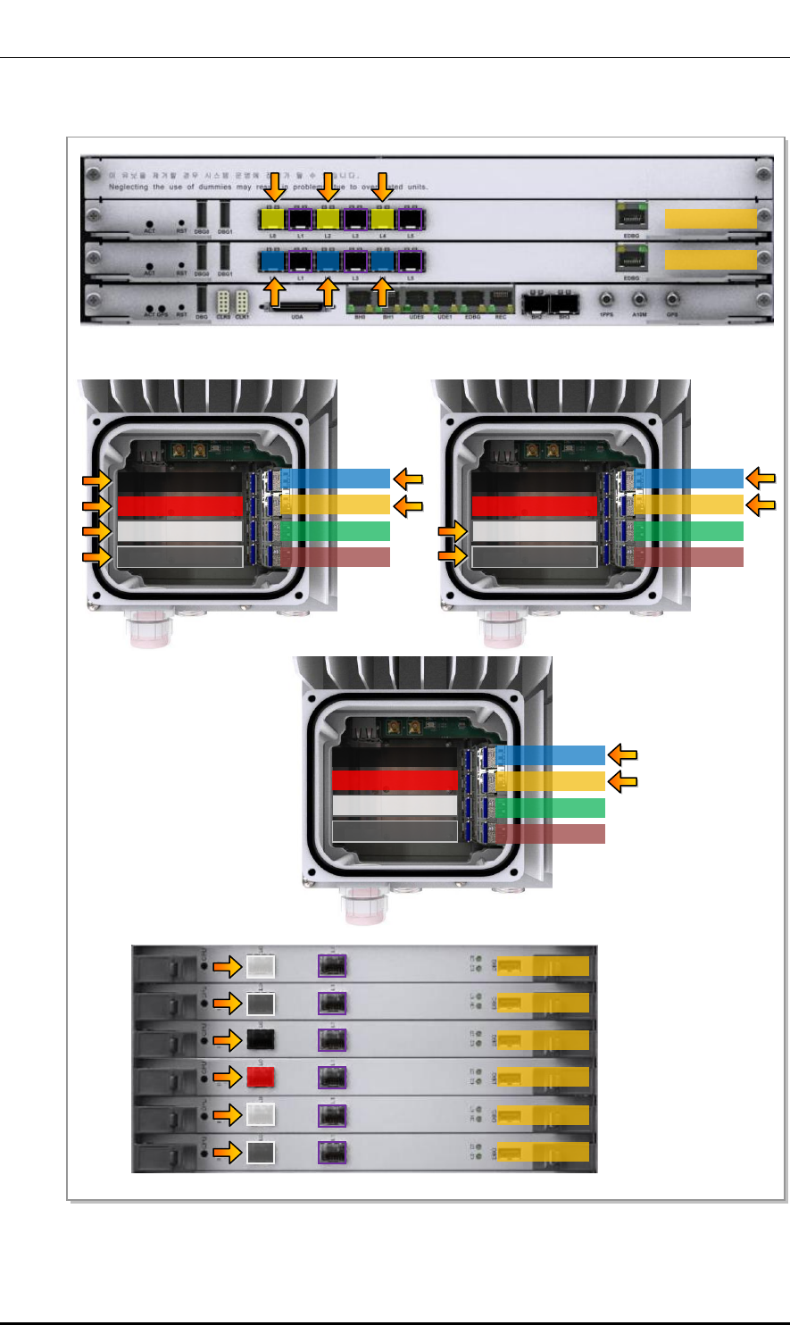
Figure 3.48 CPRI Cable Pin Map (Stacking, Case #3)
L0
L9CA #1
L9CA #0
L2
L4
Optic0 (LTE0)
Optic1 (LTE1)
Optic2 (LTE2)
Optic3 (LTE3)
L1
L3
L5
[UADU]
[RRH-B4 #0]
L0
L2
L4
L1
L3
L5
[U-RAS Flexible V2 DU]
L0
L0
L0
MRA-F #5
MRA-F #4
MRA-F #3
MRA-F #2
MRA-F #1
MRA-F #0
L1
L1
L1
L1
L1
L1
L0
L0
L0
Optic0 (LTE0)
Optic1 (LTE1)
Optic2 (LTE2)
Optic3 (LTE3)
[RRH-B4 #1]
Optic0 (LTE0)
Optic1 (LTE1)
Optic2 (LTE2)
Optic3 (LTE3)
[RRH-B4 #2]
Optic4 (WiMAX0)
Optic6 (WiMAX2)
Optic5 (WiMAX1)
Optic7 (WiMAX3)
Optic4 (WiMAX0)
Optic6 (WiMAX2)
Optic5 (WiMAX1)
Optic7 (WiMAX3)
Optic4 (WiMAX0)
Optic6 (WiMAX2)
Optic5 (WiMAX1)
Optic7 (WiMAX3)
Ver.
CHAPTER 3. Connecting Cables
3-68 © SAMSUNG Electronics Co., Ltd.
2600-00F1W8GAA
4.0
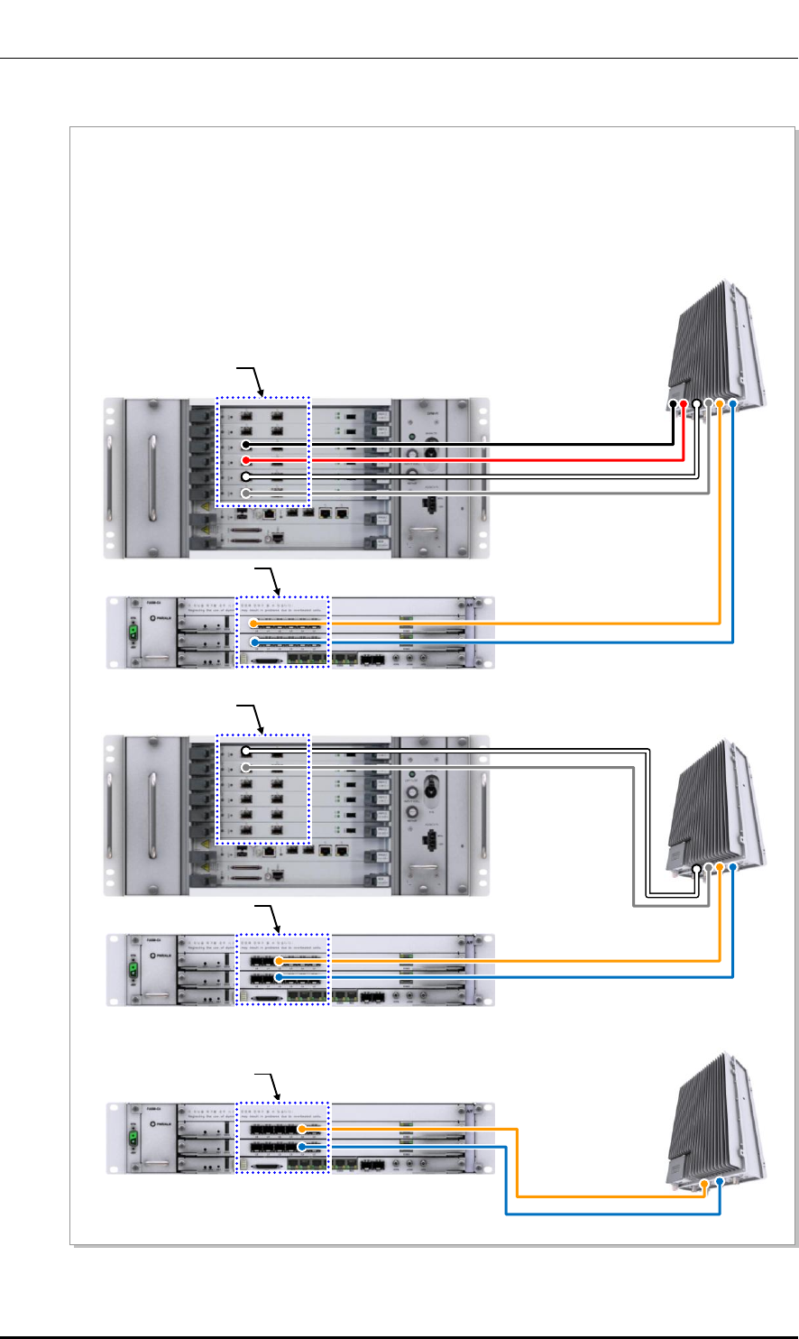
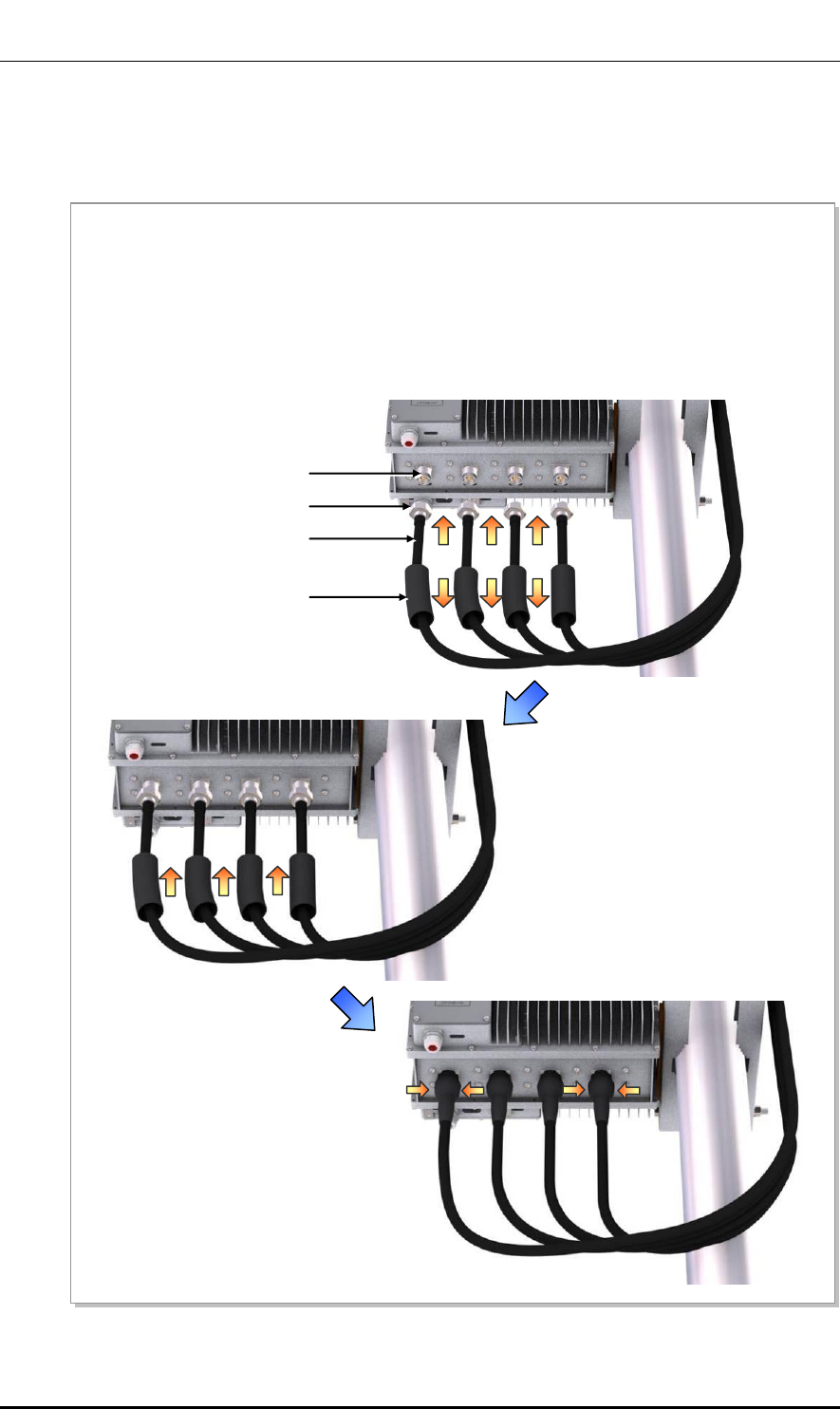
Figure 3.49 CPRI Cable Connection_Stacking, Case #3 (1)
[UADU Front]
[UADU Front]
[U-RAS Flexible V2 DU Front]
1) Install CPRI cables (RRH-B4 interface) between:
- RRH-B4 and L0, L2, and L4 ports on UADU L9CA #0 and #1
- RRH-B4 and L0 port on U-RAS Flexible V2 DU MRA-F #0-#5
2) Connect the UADU- and U-RAS Flexible V2 DU-side connectors to the following ports.
- L0, L2, and L4 ports on UADU L9CA #0 and #1
- L0 ports on U-RAS Flexible V2 DU MRA-F #0-#5
[UADU Front]
[U-RAS Flexible V2 DU Front]
[UADU Front]
[RRH-B4 #0]
‘A’
CPRI Cable
CPRI Cable
‘B’
[RRH-B4 #1]
‘A’
CPRI Cable
CPRI Cable
‘B’
[RRH-B4 #2]
‘A’
CPRI Cable

Ver.
Mobile WiMAX/TD-LTE Smart MBS, U-RAS Flexible V2 RRH-B4 Installation Manual
© SAMSUNG Electronics Co., Ltd. 3-69
2600-00F1W8GAA
4.0
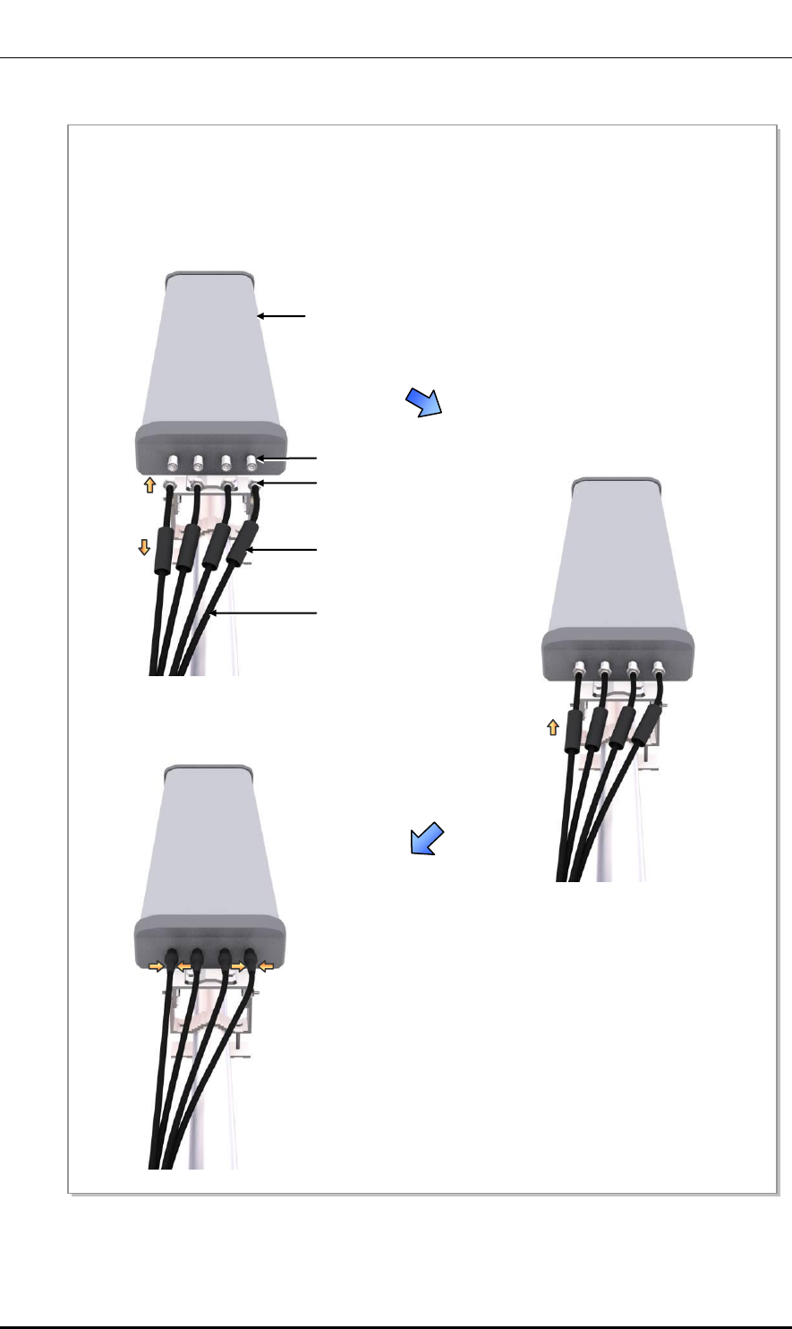
Figure 3.50 CPRI Cable Connection_Stacking, Case# 3 (2)
CPRI Cable
(RRH-B4 Interface)
CPRI Cable Connector
(LC/PC)
Optic0 (LTE0)
Optic1 (LTE1)
CPRI Cable
(RRH-B4 Interface)
CPRI Cable Connector
(LC/PC)
Optic0 (LTE0)
Optic1 (LTE1)
Detail ‘A’
CPRI Cable
(RRH-B4 Interface)
CPRI Cable Connector
(LC/PC)
Detail ‘B’
Detail ‘C’
Optic0 (LTE0)
Optic1 (LTE1)
Optic4 (WiMAX0)
Optic6 (WiMAX2)
Optic5 (WiMAX1)
Optic7 (WiMAX3)
Optic6 (WiMAX2)
Optic7 (WiMAX3)
Ver.
CHAPTER 3. Connecting Cables
3-70 © SAMSUNG Electronics Co., Ltd.
2600-00F1W8GAA
4.0
3.5.2 RET Cable Connection
Follow the steps below to connect the Remote Electrical Tilting (RET) cable to control the
antenna tilting angle remotely.
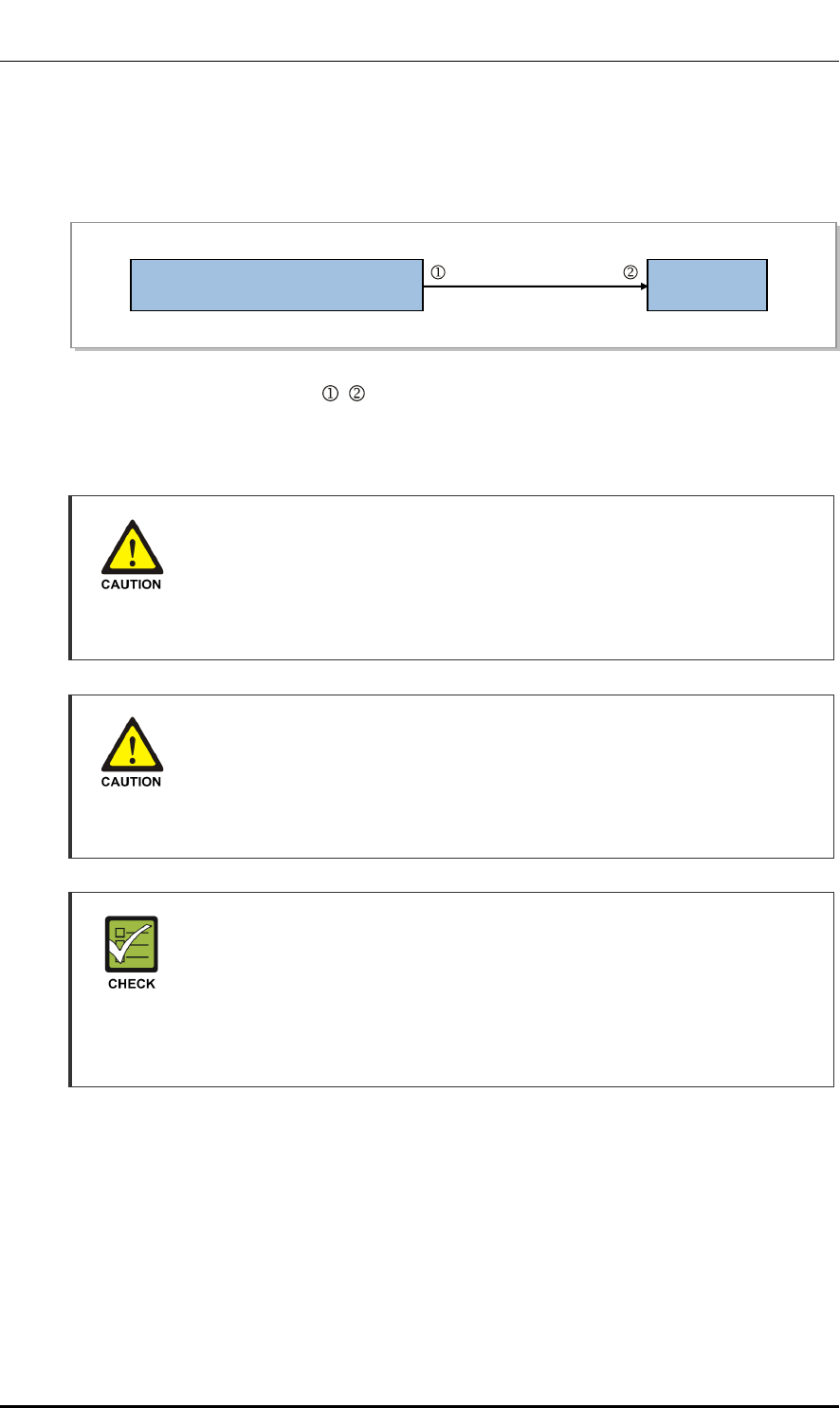
Table 3.15 RET Cable Connection
Classification
Description
Installation Section
RF Antenna~RRH-B4
Cable
RET Cable Ass’y
Connector
RS-485
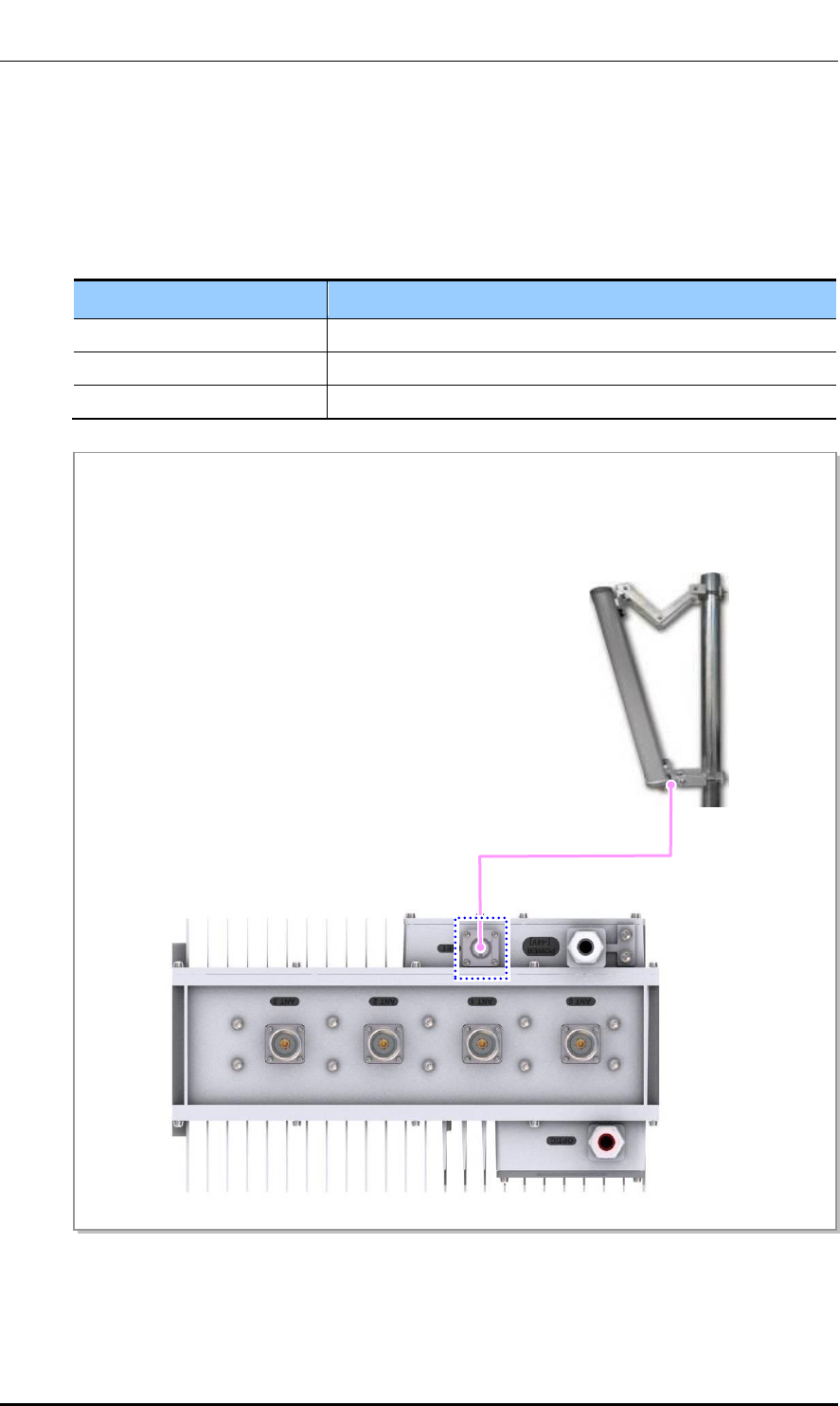
Figure 3.51 RET Cable Connection (1)
RET Cable Ass’y
1) Install a RET cable ass’y from the RF antenna to the RET port of RRH-B4
[RF Antenna]
Ver.
Mobile WiMAX/TD-LTE Smart MBS, U-RAS Flexible V2 RRH-B4 Installation Manual
© SAMSUNG Electronics Co., Ltd. 3-71
2600-00F1W8GAA
4.0
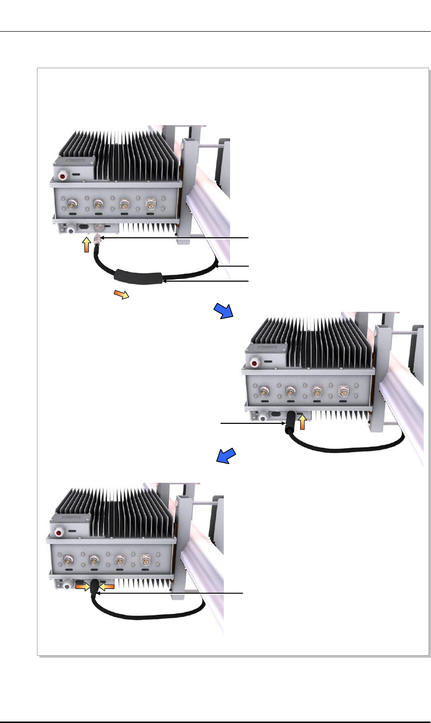
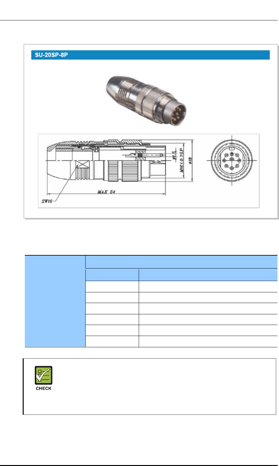
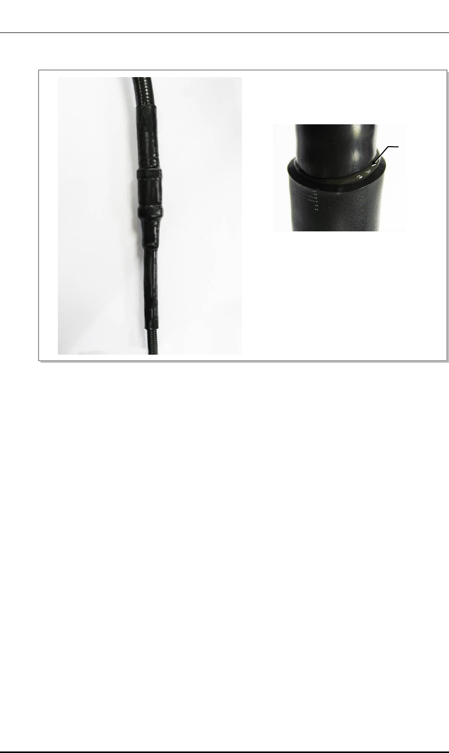
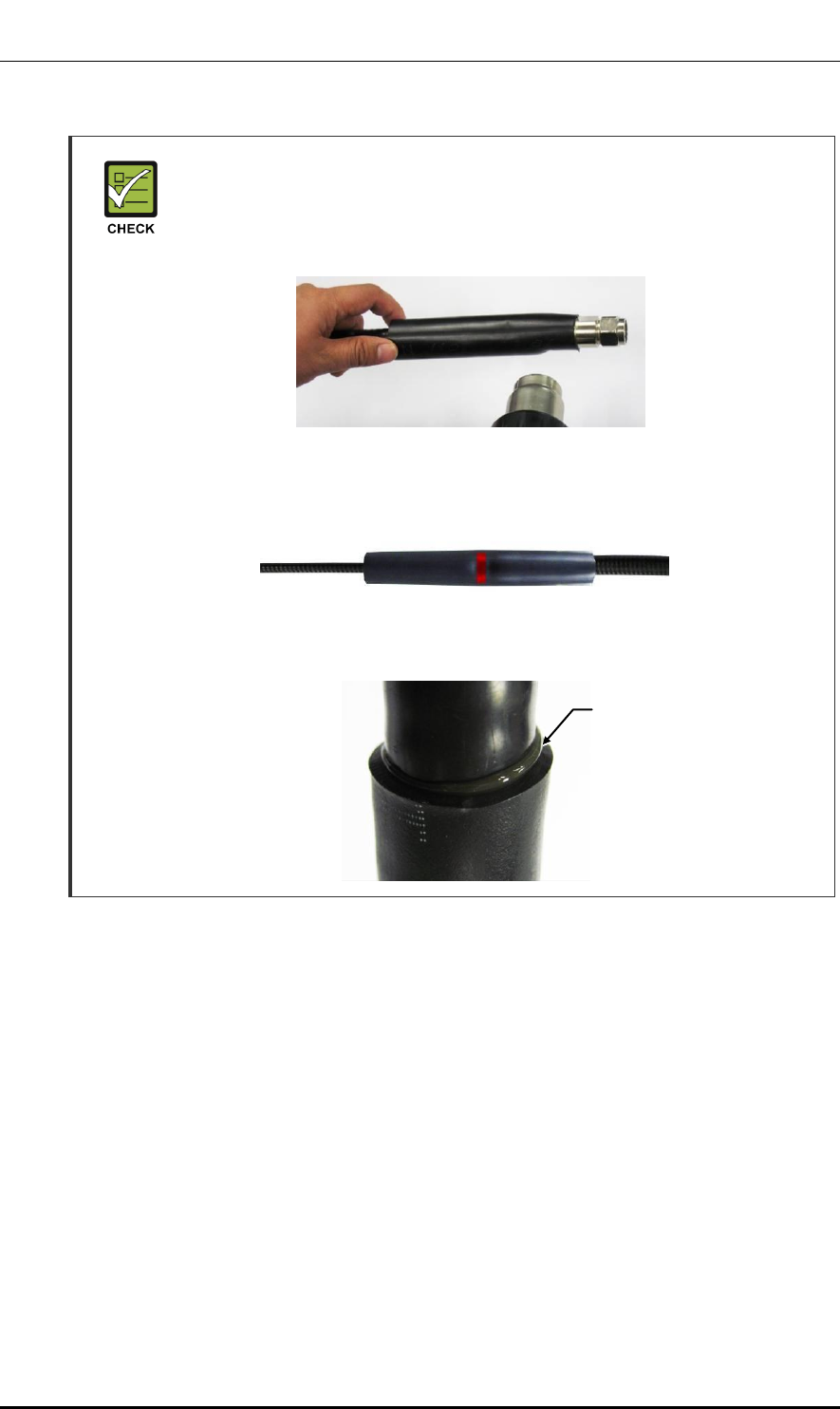
Figure 3.52 RET Cable Connection (2)
RET Connector (SAMWOO, SU-20SP-8P)
RET Cable (Shield Cable)
Heat Shrink Tube (Jelly Type)
Heat Shrink Tube (Jelly Type)
Heat Shrink Tube (Jelly Type)
2) Connect the RET cable connector to the RET port at the bottom of the RRH-B4
Ver.
CHAPTER 3. Connecting Cables
3-72 © SAMSUNG Electronics Co., Ltd.
2600-00F1W8GAA
4.0
Figure 3.53 RET Cable Connector
Table 3.16 RET Cable Connector Pin Map
RET Connector
Samwoo, SU-20SP-8P
Pin
Function
3
RS485B
4
DGND
5
RS485A
6
+21 V
7
+21 V RTN
1, 2, 8
NC
RET
- When 21 VDC volts are applied, the current supplied to the RET from RRH-B4
must be 1 A or lower.
- The exterior of the RET connector must be made of metal without vent hole or
other UL certified material.
Ver.
Mobile WiMAX/TD-LTE Smart MBS, U-RAS Flexible V2 RRH-B4 Installation Manual
© SAMSUNG Electronics Co., Ltd. 3-73
2600-00F1W8GAA
4.0
3.5.3 RF Cable Connection
Follow the steps below to connect the RF cable.
Table 3.17 RF Cable Connection
Classification
Description
Installation Section
RRH-B4~RF Antenna
Cable
RRH-B4~RF Antenna
1/2 in. Feeder Line
Connector
RRH-B4
Mini Din Type-Male
RF Antenna
Din Type-Male
Recommended
Torque Value
Mini Din Type-Male
1.45 lbf.ft (20 kgf.cm)
Din Type-Male
14.50 lbf.ft (200 kgf.cm)
Working Tools
Cable Cutter, Wire Stripper, Nipper, Torque Wrench, Spanner, Knife,
Soldering Iron, Lead
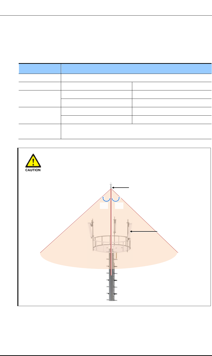
Installing the Antenna
When you install the antenna, the antenna must be within the protective angle
(left/right side 45° each from the central axis) to prevent the antenna from
lightning damage.
Lightning Rod
45°
45°
RF Antenna
Ver.
CHAPTER 3. Connecting Cables
3-74 © SAMSUNG Electronics Co., Ltd.
2600-00F1W8GAA
4.0
RF Cable Configuration
The RF cable is connected in the following two methods. Prepare and install parts based on
the method agreed by a service provider or the site conditions.
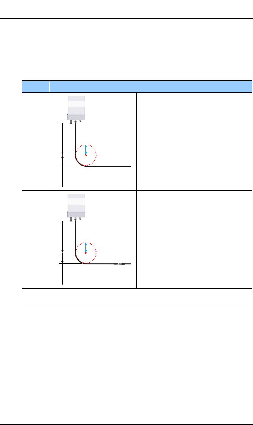
Table 3.18 RF Cable Connection at Antenna Connection Area
Case
Description
Case #1
Connect a 7/8 in. or longer feeder line directly to
the RF antenna.
- If a space for min. radius of curvature can be
secured when a 7/8 in. or longer feeder line is
used.
- If no excessive force is applied to the
connector assembled to the antenna port or
cable because the straight cable section is
long enough.
Case #2
Connect a 1/2 in. feeder line (jumper cable) to
the RF antenna.
- If a space for min. radius of curvature cannot
be secured when a 7/8 in. or longer feeder line
is used.
- If excessive force is applied to the connector
assembled to the antenna port or cable and it
may cause poor contact or damage because
the straight cable section is not long enough.
※ 7/8 in. or longer feeder line: 7/8 in./1 1/4 in./1 5/8 in. feeder line, etc.
※ The RF cable must be connected based on the method agreed by a provider or the site conditions.
R’
RF Antenna
Straight cable
section
Min. radius
of curvature
Straight cable
section
Min. radius
of curvature
R’
RF Antenna
Ver.
Mobile WiMAX/TD-LTE Smart MBS, U-RAS Flexible V2 RRH-B4 Installation Manual
© SAMSUNG Electronics Co., Ltd. 3-75
2600-00F1W8GAA
4.0
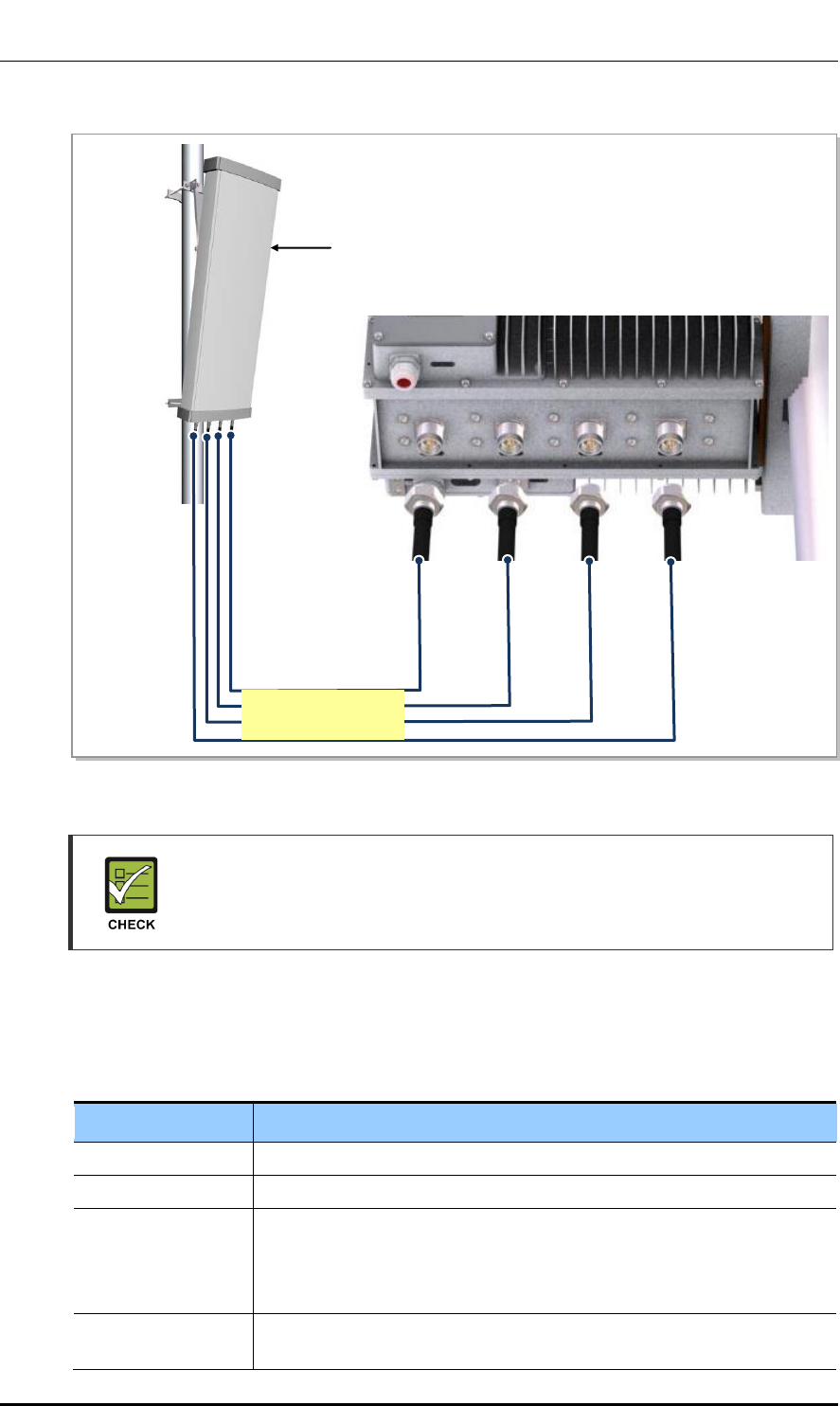
Figure 3.54 RF Cable Configuration
RF Antenna Connector
As different connector types may be used depending on the RF antenna type,
check the antenna connector before connecting the cable.
RF Cable Identification Tag Installation
Attach the identification tape in the below table to the RF cable.
Table 3.19 RF Cable Identification Tag
Category
Description
Installation position
Attach the identification tag to the both ends of the antenna.
Materials
Use the material of aluminum coated by vinyl for the identification tag.
Fixing method
- Antenna side: Attach the tag to the feeder line using binding strings
through the two holes on the tag.
- Equipment Side: Cover up the feeder line with the tag and fix it using
binding strings through the two holes on the tag.
Identification method
The markings must be prevented from being erased by using relief
engraving or coated labels.
RF Antenna
[RRH-B4]
1/2 in. Feeder Line
(RRH-B4~RF Antenna)
Ver.
CHAPTER 3. Connecting Cables
3-76 © SAMSUNG Electronics Co., Ltd.
2600-00F1W8GAA
4.0
RF Cable Connection
Follow the steps below to connect the cable between RRH-B4 and RF antenna.
Figure 3.55 RF Cable Connection (1)
Mini Din Type-Male Connector
1/2 in. Feeder Line
(RRH-B4 RF Port~RF Antenna)
1) Before connecting the connector to the RF port (Mini Din type-female) at the bottom of RRH-B4, insert a
heat shrink tube (jelly type).
2) After connecting the connector, place the heat shrink tube inserted in the previous step at the connecting
area and shrink it using a heating gun.
Mini Din Type-Female Connector
Heat Shrink Tube (Jelly Type)
Ver.
Mobile WiMAX/TD-LTE Smart MBS, U-RAS Flexible V2 RRH-B4 Installation Manual
© SAMSUNG Electronics Co., Ltd. 3-77
2600-00F1W8GAA
4.0
Figure 3.56 RF Cable Connection (2)
3) Insert a heat shrink tube (jelly type) for finishing at the end of the antenna jumper cable (1/2 in. feeder
line) with a Din type-male connector installed and then connect to the antenna input port.
4) When the connector is connected completely, insert the heat shrink tube inserted in the previous step
up to the connecting area and shrink it using a heating gun.
Antenna Connector (Din Type-Female)
1/2 in. Feeder Line
Heat Shrink Tube (Jelly Type)
RF Antenna
Din Type-Male Connector
for 1/2 in. Feeder Line
Ver.
CHAPTER 3. Connecting Cables
3-78 © SAMSUNG Electronics Co., Ltd.
2600-00F1W8GAA
4.0
Checking RF Cable Connection
After connecting the RF cables, perform the continuity test and feeder cable return loss to
check if the RF cable is changed and measure VSWR of antenna and RF cable.
Measure all cables of section ~ . The measured VSWR should be the specification
value or less. If the VSWR exceeds the specification value, disassemble the connector and
measure each section separately.
Checking VSWR for Minimum Cable Bend Radius and Length of RF Cable
If the VSWR value for minimum cable bend radius and length of RF cable is not
applied, system may not work properly because RF signals cannot transmit or
receive smoothly. So, the VSWR value for minimum cable bend radius and length
of RF cable must be checked and applied.
Cautions When Measuring VSWR
When measuring VSWR, if you open the antenna port when the transmission
output is not completely off, a spike signal may flow into the reception path, which
may cause damage to LNA. Make sure the transmission output is completely off
when measuring VSWR.
Checking the Specifications of Antenna/Arrestor Connector
Depending on the supplier or manufacturer of antenna/arrestor the connector
type may be different. Also, the detail specifications of a connector may be
different depending on cable type even for the same connector type.
Therefore, check the detail specifications of a connector before preparing parts.
Ex) Din Type-Male: for 1/2 in. Feeder line, for 7/8 in. Feeder Line
Connection Part of System External
Interface Connector
Antenna
Ver.
Mobile WiMAX/TD-LTE Smart MBS, U-RAS Flexible V2 RRH-B4 Installation Manual
© SAMSUNG Electronics Co., Ltd. 4-1
2600-00F1W8GAA
4.0
CHAPTER 4. Checking Installation
Status
4.1 Installation Checking Procedure
Below is the procedure to check installation status.
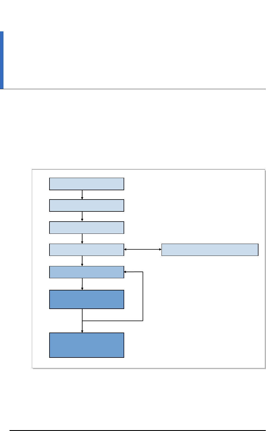
Figure 4.1 Installation Checking Procedure
Nok
OK
Sharing Inspection Results
Taking Corrective Actions
Checking the Results of
Corrective Actions
On-site Inspection
Inspection Checklist
Inspection Checklist/Corrective Actions
Sharing the Results of
Corrective Actions and
Preparing Preventive Plan
Inspection Plan

Ver.
CHAPTER 4. Checking Installation Status
4-2 © SAMSUNG Electronics Co., Ltd.
2600-00F1W8GAA
4.0
Inspection Plan
Create an inspection sheet per system and select an inspector to set an inspection schedule
per site.
On-site Inspection and Inspection Checklist
The on-site inspection is to perform inspection visually or using instruments for each
specification, standard, and installation status, etc. based on the inspection checklist
actually at a site where the system ins installed.
The inspector must record the results onto the inspection checklist during or after filed
inspection.
Sharing Inspection Results and Taking Corrective Actions
The inspector must share the inspection results (inspection checklist/corrective actions)
with a installation operator and the installation operator must take the corrective actions if
necessary after reviewing the requirements.
Checking the Results of Corrective Actions
The inspector must check if the corrective actions are properly taken. If they are not sufficient,
the inspector must ask the installation operator to take the corrective actions again.
Sharing the Results of Corrective Actions and Preparing Preventive Plan
After the corrective actions are all completed, the inspector must share the results with the
installation operator and relevant departments and prepare a preventive plan to prevent the
same or similar problems from re-occurring.
Table 4.1 Construction Situation Checklist
Category
Check Items
Criteria
Result
Pass
Fail
Installing
Equipment
Appearance of equipment and
mechanical parts
Equipment damage such as Dent,
scratch and crack, etc.
Placement of equipment and
mechanical parts
Maintenance and horizontal/vertical
placement
Leveling condition of equipment
and mechanical parts
Horizontal/vertical fixing
(level, weight, rubber hose, etc.)
Validity of status and
specifications of tightening
bolt/nut/washer, etc.
Visual inspection and magnet check
Compliance with tightening torque
value
Board/blank panel installation
status
Checking assembly status
Insulation status
Checking electrical contact between
insulators (insulation resistance tester)
Other works (cable duct
installation status, etc.)
Checking position and installation
status

Ver.
Mobile WiMAX/TD-LTE Smart MBS, U-RAS Flexible V2 RRH-B4 Installation Manual
© SAMSUNG Electronics Co., Ltd. 4-3
2600-00F1W8GAA
4.0
Table 4.1 Construction Situation Checklist (Continued)
Category
Check Items
Criteria
Result
Pass
Fail
Grounding
Status of ground bar
installation per usage
Checking the separation of
communication/power/lightning
grounding
Cable Size
Checking specifications such as
thickness, etc.
Cabling and binding status
Cable damage/properness installation
route
Checking binding interval and the
condition of used materials
Cable connection
Assembly and tightening condition of a
pressure terminal
Checking compliance with tightening
torque value
Installation status of cable
tag
Checking position, marking, and tag
installation type
Power
Installation status of power
supply and circuit breaker
Power supply capacity/input voltage
(tester)
Checking circuit breaker type and
capacity
Cable Size
Checking thickness and length
limitation
Cabling and binding status
Cable damage/properness installation
route
Checking binding interval and the
condition of used materials
Cable connection
Cable damage/properness installation
route
Checking binding interval and the
condition of used materials
Installation status of cable
tag
Checking position, marking, and tag
installation type
Other data
cables
Cable size
Checking cable specifications per
usage
Cabling and binding status
Checking cable damage/properness
installation route, binding distance and
condition of used materials
Cable connection
Checking cable connection (Pin Map),
assembly and tightening status of a
connector and compliance with tightening
torque value
Installation status of cable
tag
Checking position, marking, and tag
installation type

Ver.
CHAPTER 4. Checking Installation Status
4-4 © SAMSUNG Electronics Co., Ltd.
2600-00F1W8GAA
4.0
Table 4.1 Construction Situation Checklist (Continued)
Category
Check Items
Criteria
Result
Pass
Fail
RF
Antenna installation status
Checking specifications, installation
position, fixing status, and gap between
antennas
Installation status of
arrestor/line
amplifier/splitter, etc.
Checking specifications, installation
position, and fixing status
Cabling and binding status
Checking cable damage/properness of
installation route/binding distance and
the condition of used materials
Cable connection
Checking cable connection status,
connector assembly and tightening
status, compliance with tightening
torque value, and finishing
Installation of cable tag
Checking position, marking, and tag
installation type
Others
Reserved ports and cable
inlet status
Finishing (dust cap, etc.)
Connection of equipment
I/O port (Conduit/Cable
Gland)
Checking tightening status
Installation of cable
installation route
Installation of cable tray and duct, etc.
Status of inside/outside of
the equipment and system
surrounding area
Checking the stocking condition of
waste parts, waste materials, packing
materials, etc.
Opinion

Ver.
Mobile WiMAX/TD-LTE Smart MBS, U-RAS Flexible V2 RRH-B4 Installation Manual
© SAMSUNG Electronics Co., Ltd. A-1
2600-00F1W8GAA
4.0
ANNEX A. Sector Antenna Installation
A.1 Cautions when Installing a Sector Antenna
Precautions of antenna installation are as follows.
Sector antennas should be installed vertically. (±1°)
Antenna is the precise material, so be careful not to make damage or form change.
When moving antenna, use the tool suitable to rating. In addition, use the rated
carrying device which is at least 200 % or more than antenna considering the stability.
Be careful not to give too much strength to the antenna.
If it rains, suspend connecting the feeder cable and antenna.
Fix it after adjusting the direction of antenna exactly.
Distance between steel tower and antenna and the distance between send-receive
antennas are based on the antenna layout.
Attach the antenna on the position specified in the drawing.
Install the antenna not to make a feature change of the antenna considering the
direction of the radiation.
Connect the antenna not making the alien substance flowed so that Passive Inter-
Modulation Distortion (PMID) is not affected.
Measure VSWR of all antennas and the value should be within the regulated value.
A.2 Sector Antenna Layout
The method of sector antenna layout is as follows.
1) Use the transit to adjust the antenna installation direction exactly.
2) Fix the direction of the sector antenna, same as the angle settled when designing the
cell after installing the steel tower.
3) Arrange the antennas of each sector to the sector directional angle at right angles by
adjusting the distance between antenna and steel tower.
In the event of the station whose the direction between sectors is not 120°, install it to
make the steel tower and antenna direction different being careful of the tilt and azimuth.
4) For circular platform, separate the antenna interval at maximum.

Ver.
ANNEX A. Sector Antenna Installation
A-2 © SAMSUNG Electronics Co., Ltd.
2600-00F1W8GAA
4.0
A.3 Sector Antenna Installation
The method of sector antenna installation is as follows.
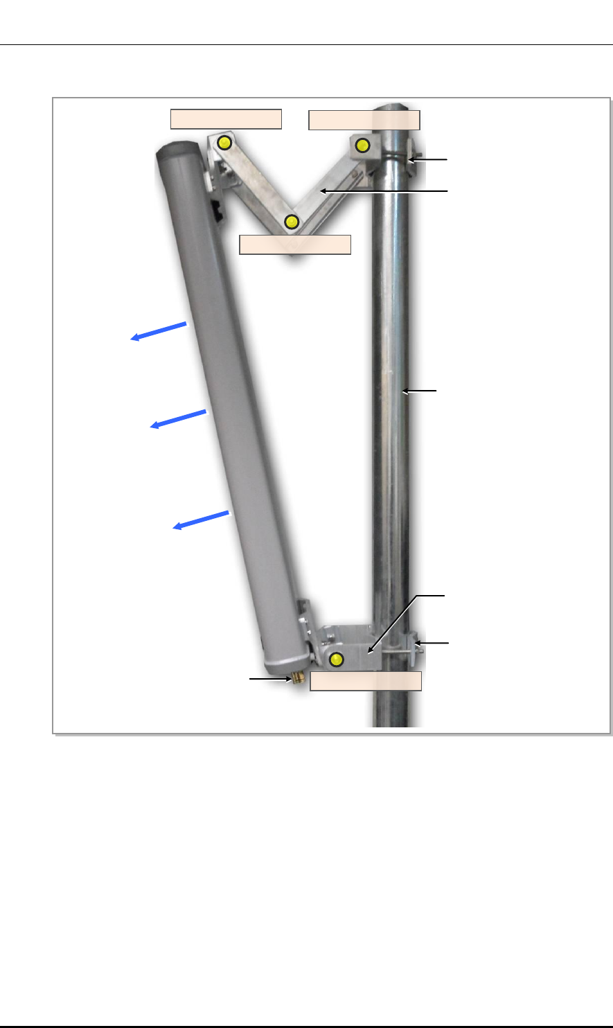
1) Put up an antenna pole and insert the sector antenna into the antenna pole using a
fixing clamp.
2) Set the antenna’s up/down tilt to 0° and fix the fixing clamps at the top and bottom.
3) Adjust the tilted angle of the antenna by taking the signal strength into account.
The bolts on the upper and lower guide clamps must be loose as to allow angle
adjustment of the antenna.
4) After adjusting the antenna angle, tighten up the 4 loose bolts on the upper and lower
guide clamps.
Ver.
Mobile WiMAX/TD-LTE Smart MBS, U-RAS Flexible V2 RRH-B4 Installation Manual
© SAMSUNG Electronics Co., Ltd. A-3
2600-00F1W8GAA
4.0
Figure A.1 Sector Antenna
Antenna Input Port
Pole
Main Radiation Direction
Upper Fixing Clamp
Lower Fixing Clamp
Upper Guide Clamp
Lower Guide Clamp
Guide Clamp Bolt_2
Guide Clamp Bolt_1
Guide Clamp Bolt_3
Guide Clamp Bolt_4
Ver.
ANNEX A. Sector Antenna Installation
A-4 © SAMSUNG Electronics Co., Ltd.
2600-00F1W8GAA
4.0
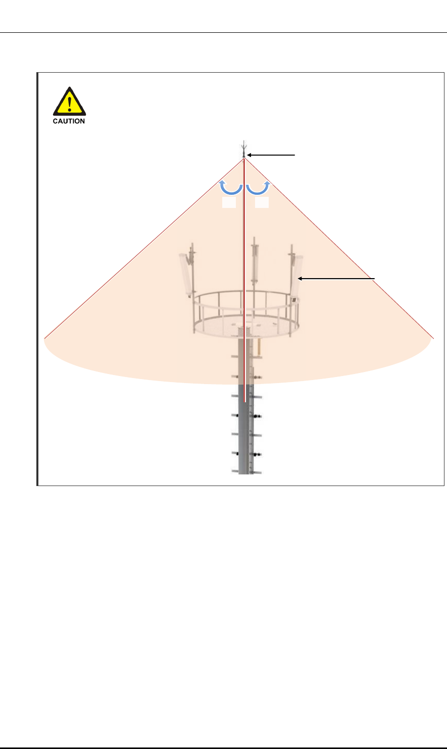
Installing the Antenna
When you install the antenna, the antenna must be within the protective angle
(left/right side 45° each from the central axis) to prevent the antenna from
lightning damage.
Lightning Rod
45°
45°
Sector Antenna
Ver.
Mobile WiMAX/TD-LTE Smart MBS, U-RAS Flexible V2 RRH-B4 Installation Manual
© SAMSUNG Electronics Co., Ltd. B-1
2600-00F1W8GAA
4.0
ANNEX B. Installing Feeder Cable
B.1 Cautions When Installing Feeder Cable
When installing the feeder cable (GPS/RF cable), the following cautions shall be
considered:
Put a plate to work not to make damage for the surface of the feeder cable.
If there is external damage of the feeder cable, cut the damaged part and work wiring.
After connecting the antenna to the feeder cable, finish the connection part of the
contracted pipe using the contracted tube.
Attach the cognitive tapes to the both ends of the feeder cable, which makes it easy to
recognize.
When connecting cabinet, antenna and lightening arrestor, etc. to the feeder cable,
connect strongly to prevent from generating reflected wave.
The curvature radius should be maximized, keep the minimum curvature radius.
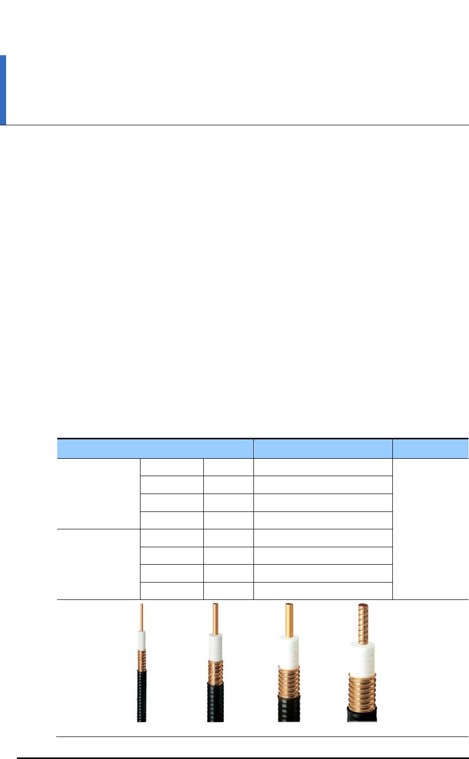
Table B.1 Curvature Radius of Feeder Cable for Outdoor
Specification
Allowed Radius of Curvature
Remark
LS Feeder Line
HFC-12D
1/2 in.
4.02 in. (125 mm)
Outdoor
HFC-22D
7/8 in.
9.84 in. (250 mm)
HFC-33D
1-1/4 in.
14.96 in. (380 mm)
HFC-42D
1-5/8 in.
20.08 in. (510 mm)
RFS Feeder Line
LCF12-50
1/2 in.
4.92 in. (125 mm)
LCF78-50
7/8 in.
9.84 in. (250 mm)
LCFS114-50
1-1/4 in.
14.96 in. (380 mm)
LCF158-50
1-5/8 in.
19.69 in. (500 mm)
1/2 in.
7/8 in.
1-1/4 in.
1-5/8 in.

Ver.
ANNEX B. Installing Feeder Cable
B-2 © SAMSUNG Electronics Co., Ltd.
2600-00F1W8GAA
4.0
Table B.2 Curvature Radius of Feeder Cable for Indoor (Based on LS Feeder Line)
Specification
Allowed Radius of Curvature
Remark
LS Feeder Line
HFSC 6D
1/4 in.
0.98 in. (25 mm)
Indoor
HFSC 10D
3/8 in.
0.98 in. (25 mm)
HFSC 12D
1/2 in.
1.26 in. (32 mm)
HFSC 22D
7/8 in.
4.92 in. (125 mm)
RFS Feeder Line
SCF14-50
1/4 in.
0.98 in. (25 mm)
SCF38-50
3/8 in.
0.98 in. (25 mm)
SCF12-50
1/2 in.
1.26 in. (32 mm)
UCF78-50
7/8 in.
4.92 in. (125 mm)
Table B.3 Curvature Radius of LMR-400 (Based on Times Microwave System)
Specification
Allowed Radius of Curvature
Remark
LMR-400
1 in. (25.4 mm)
Installation
4 in. (101.6 mm)
Repeated
Radius of Curvature of Feeder Line
When installing a feeder line, the radius of curvature of the sections where cables
bent should be larger than the allowed radius of curvature. If the radius of
curvature for the feeder line installation is less than the allowed radius of
curvature, it may affect the performance of the system.
1/4 in.
3/8 in.
1/2 in.
7/8 in.
Ver.
Mobile WiMAX/TD-LTE Smart MBS, U-RAS Flexible V2 RRH-B4 Installation Manual
© SAMSUNG Electronics Co., Ltd. B-3
2600-00F1W8GAA
4.0
Ensure that the feeder cable does not interfere with steel towers, ladders and in the
areas chiefly used by people.
Connect the connector to the antenna in a straight line and after connecting, do not
apply excessive force.
Use the vinyl tape for electricity and heat shrink tube for the external exposed part of
the connector not to avoid leak water.
Wind the self-bonding rubber tape overlapping (keep a distance as the half size of
rubber tape) to the connector connection part and wind the vinyl tape for electricity to
the 2 times or more and then cover with the jelly type heat shrink tube.
Connection of Feeder Cable Connector
Connecting the feeder cable connector is critical process, so the qualified workers
who finished the related education should perform.
Table B.4 Connector Connection Torque Value
Connector
Torque Value
SMA connector
0.18 lbf·ft (2.5 kgf·cm)
TNC connector
0.65 lbf·ft (9 kgf·cm)
N-type connector
1.45 lbf·ft (20 kgf·cm)
Din-type connector
14.46 lbf·ft (200 kgf·cm)
Ver.
ANNEX B. Installing Feeder Cable
B-4 © SAMSUNG Electronics Co., Ltd.
2600-00F1W8GAA
4.0
B.2 7/8 in. Feeder Line Ground
Ground Kit
Ground the 7/8 in. feeder line using the grounding kit located under the Tower Ground Bar
(TGB) installed in the lower section of the tower or in the cable duct.
The procedure for connecting the ground kit to the 7/8 in. feeder line is as follows:
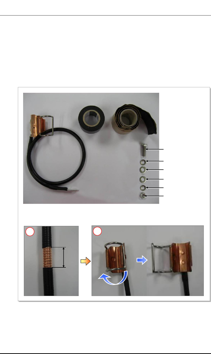
Figure B.1 7/8 in. Feeder Line Grounding (1)
2.17 in.
(55 mm)
M6 Hex. Nut
Ground Kit
Insulation Tape
Rubber Tape
M6 × 25L Hex. Bolt
M6 Spring Washer
M6 Plane Washer
M6 Plane Washer
M6 Spring Washer
1) Remove about 2.17 in. (55 mm) of the sheath of cable when the 7/8 in. feeder line is used.
2) Open it by returning hook of the clamp fixing for Ground kit in the left direction.
1
2
Ver.
Mobile WiMAX/TD-LTE Smart MBS, U-RAS Flexible V2 RRH-B4 Installation Manual
© SAMSUNG Electronics Co., Ltd. B-5
2600-00F1W8GAA
4.0
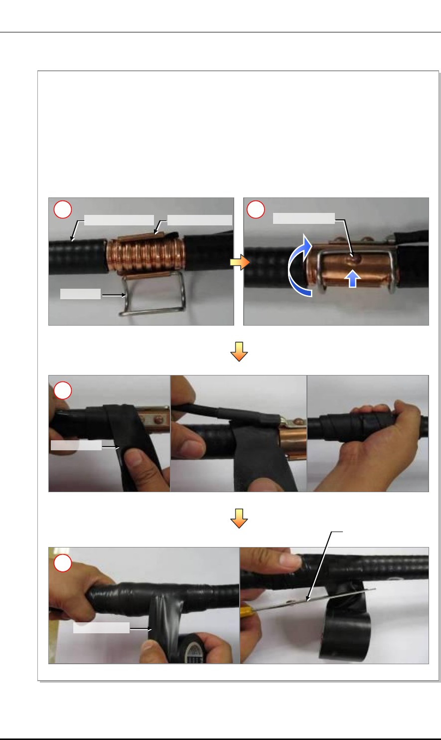
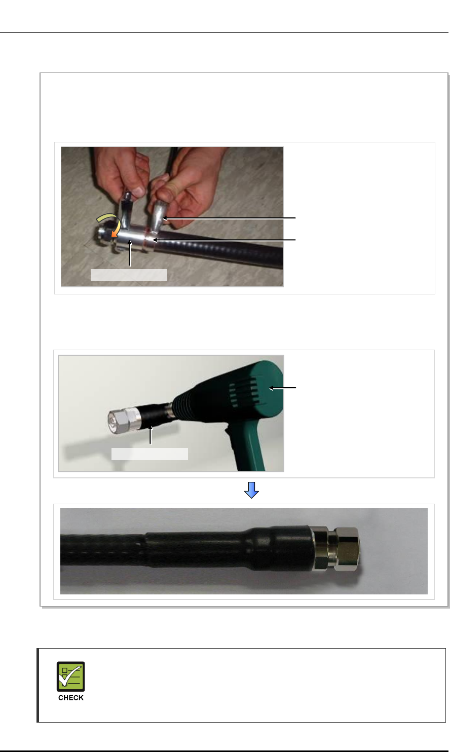
Figure B.2 7/8 in. Feeder Line Grounding (2)
Protrusion area
Clamp lock
Ground Kit Clamp
Scissors (knife)
Rubber Tape
Insulation Tape
3) Insert the ground kit clamp into the place from which the 7/8 in. feeder line sheath is removed.
4) Pull the clamp lock to the upward so that the lock can be hung on the global protrusion area on the side.
5) Overlap the exposed part of the ground kit clamp using rubber tape (Keep a distance as the half size of
rubber tape) and press it with your hands lightly to make rubber tape adhere well.
6) Wrap the part where the rubber tape is attached using insulation tape two times or more. When cutting
off the tape, cut it off neatly using a cutting device such as scissors or a knife.
6
7/8 in. Feeder Line
4
3
5
Ver.
ANNEX B. Installing Feeder Cable
B-6 © SAMSUNG Electronics Co., Ltd.
2600-00F1W8GAA
4.0
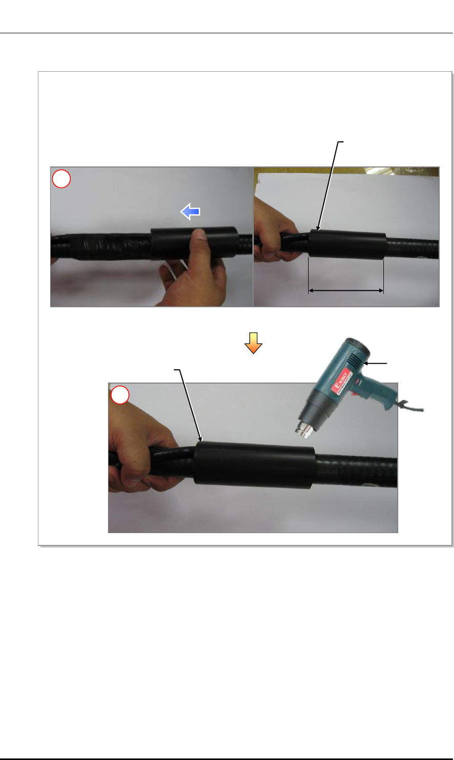
Figure B.3 7/8 in. Feeder Line Grounding (3)
7.87 in.
(200 mm)
Heating Gun
Heat Shrink Tube
Heat Shrink Tube
7) Align the heat shrink tube inserted when installing the 7/8 in. feeder line into the fixing part of the ground kit.
- Heat shrink tube: jelly type, Φ 1.65 in., 7.87 in. (Φ 42 mm, 200 mm)
8) Shrink the heat shrink tube by heating gun.
7
8
Ver.
Mobile WiMAX/TD-LTE Smart MBS, U-RAS Flexible V2 RRH-B4 Installation Manual
© SAMSUNG Electronics Co., Ltd. B-7
2600-00F1W8GAA
4.0
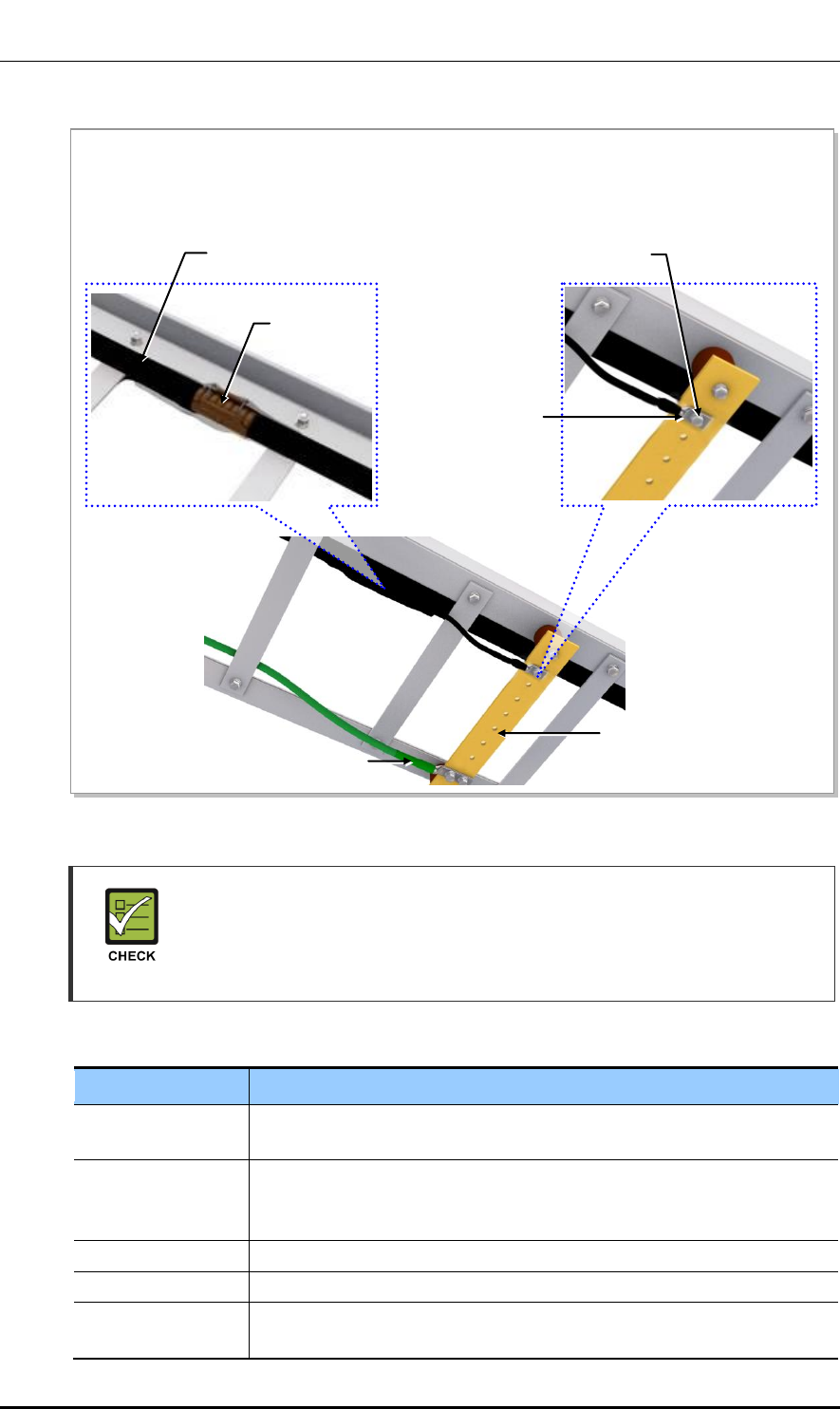
Figure B.4 7/8 in. Feeder Line Grounding (4)
Checking the Ground Kit and TGB Specifications
The specifications, clamp, and pressure terminal type of the ground kit and TGB
differ depending on manufacturers. Make sure to check the specifications of the
ground kit and TGB, and identify the installation method before installing it.
Table B.5 TGB Installation Example
Category
Description
TGB Usage
Earth terminal board for RF cable for grounding in using the feeder line of
more than 7/8 in.
TGB Location
Lower section of cable rack in feeder cable duck
- Less than 65.62 ft (20 m): 1 (Ex. steel tower lower section)
- Exceed 65.62 ft (20 m): 2 or more (Ex. steel tower lower and upper section)
Material
Pure copper
Installation Method
Using the insulator to separate from the steel tower electrically
Connection Method
Extract the GV 35 mm2 ground cable to the direction of the floor and weld it
to the tower’s ground cable.
9) After the ground kit has been installed to the 7/8 in. feeder line, attach the pressure terminal (1 hole) of
the ground cable connected to the ground kit to the TGB.
10) When attaching the pressure terminal, use M6 × 25L hex. Bolts.
TGB (Tower Ground Bar)
TGB Ground Cable (F-GV 35 mm2 × 1C)
M6 × 25L Hex. Bolt (STS304)
Pressure Terminal
(1 Hole)
Ground kit
7/8 in. Feeder Line
Ver.
ANNEX B. Installing Feeder Cable
B-8 © SAMSUNG Electronics Co., Ltd.
2600-00F1W8GAA
4.0
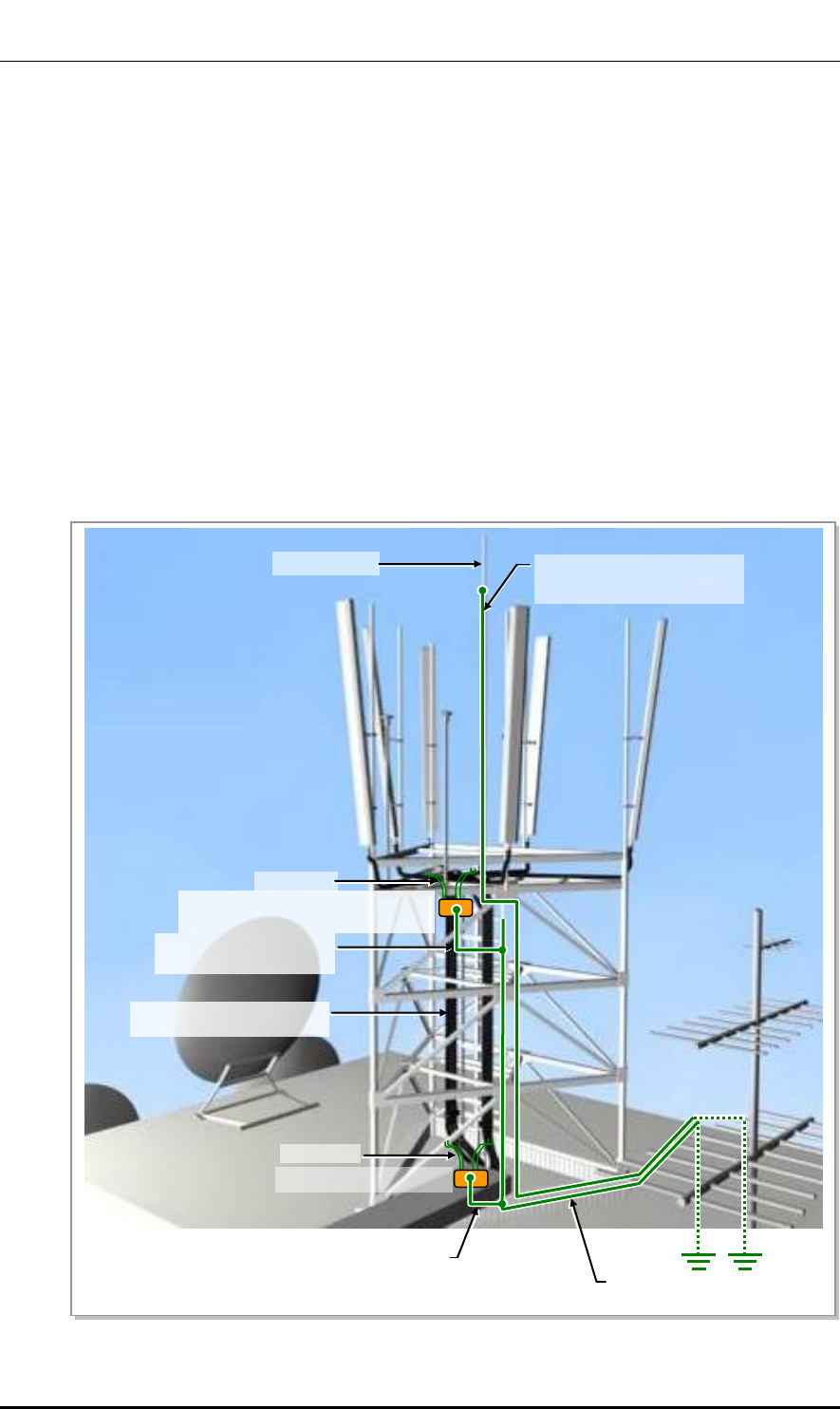
B.3 Tower Ground Construction
1) Install a Tower Ground Bar (TGB) that will be used to ground a RF cable onto the
tower. If the height of the tower is exceeds 65.62 ft (20 m), two or more TGBs should be
installed (onto the lower and upper sections of the tower). If the tower is 65.62 ft (20 m)
or less, one TGB should be installed. Since the TGB installation location and the
number of TGBs to be installed can differ depending on the system environment and
provider’s standards, consult your service provider.
2) Each TGB should be grounded and separated from other grounds. If there is an
existing ground bar or ground cable for TGB, install the TGB by branching from it
using a ground cable (GV35 mm2 × 1C) ground cable. (However, the specification of
TGB ground cable can be different, defending on the standard of service provider.)
3) Tighten the Ground Kit (RF cable grounding assembly) to the TGB ground terminal
and the tower hole using the pressure terminal hole attached at the end of the ground
kit’s ground cable.
Figure B.5 Connecting the Tower Ground Cable
Lightning Rod
RF cable
(7/8 in. Feeder Line or more)
Ground Kit
TGB (Tower Ground Bar)
[Tower Height>65.62 ft (20 m)]
TGB Ground Cable
(F-GV 35 mm2 × 1C)
Lightning Rod Ground Cable
(GV 95 mm2 × 1C)
TGB (Tower Ground Bar)
Ground Kit
TGB Ground Cable
(F-GV 35 mm2 × 1C)
TGB Ground Cable
(F-GV 95 mm2 × 1C)
Ver.
Mobile WiMAX/TD-LTE Smart MBS, U-RAS Flexible V2 RRH-B4 Installation Manual
© SAMSUNG Electronics Co., Ltd. C-1
2600-00F1W8GAA
4.0
ANNEX C. Connector Assembly
C.1 RJ-45 (Shield Type)
Procedure that assembles the RJ-45 (shield type) connector is as follows:
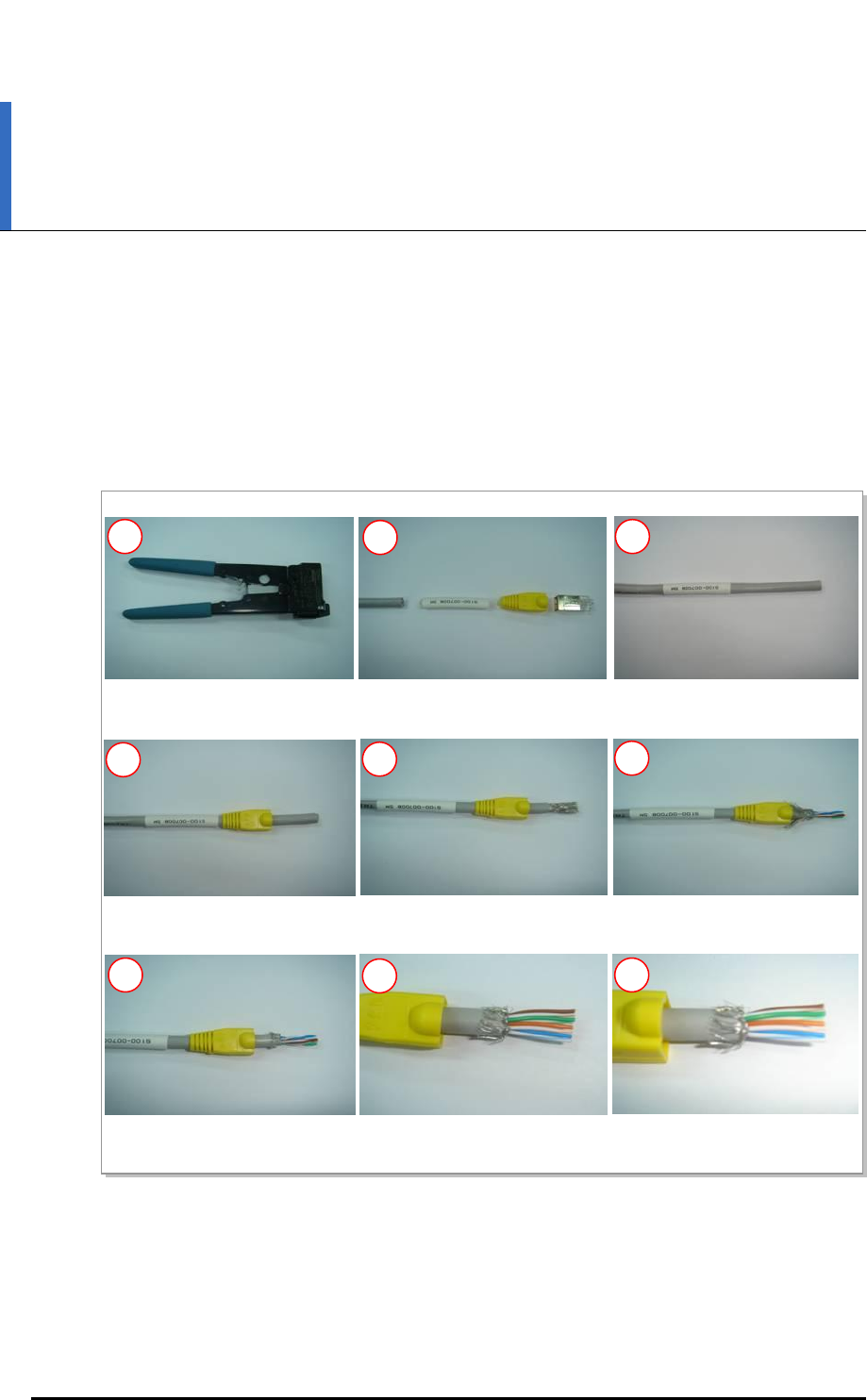
Figure C.1 Assembling the RJ-45 Connector (Shield Type) (1)
1), 2) Prepare work tools and materials.
4) Pass the cable through the
RJ-45 cap.
5) Remove the coating 0.67 in.
(17 mm) from the end.
6) Push the shield backward,
and cut the aluminum shield.
7) Cut the shield leaving a 0.2 in.
(5 mm) of it.
8) Arrange the cable in reference
to the pin map.
9) Cut the cable to make it
0.47 in.(12 mm) long.
3) Pass the cable through the
marking tube.
1
2
3
4
5
6
7
8
9
Ver.
ANNEX C. Connector Assembly
C-2 © SAMSUNG Electronics Co., Ltd.
2600-00F1W8GAA
4.0
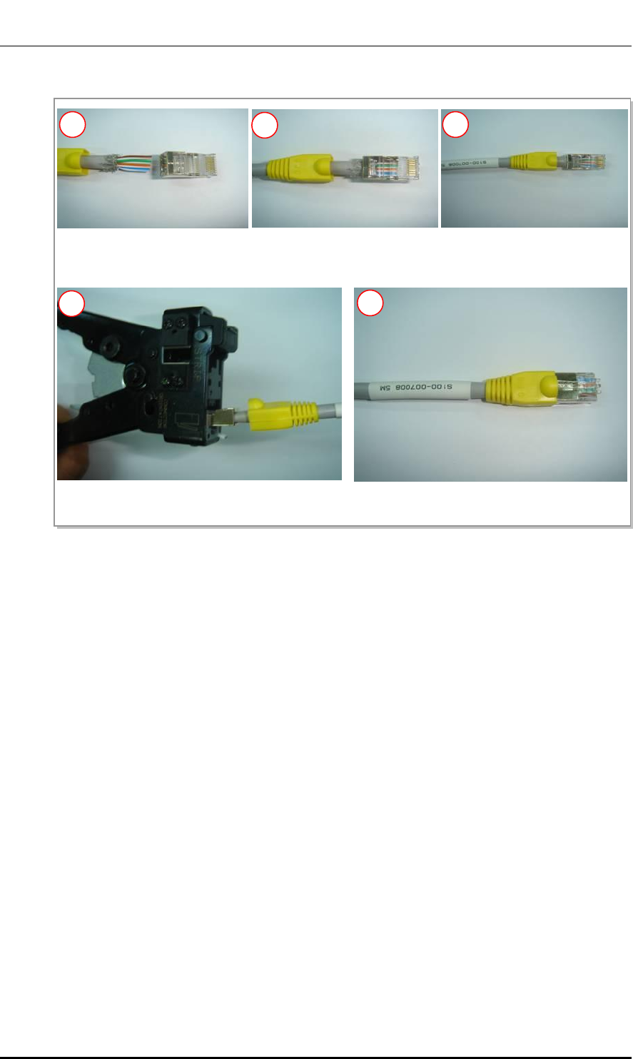
Figure C.2 Assembling the RJ-45 Connector (Shield Type) (2)
10) Insert the RJ-45 modular jack.
11) Make sure that the shield does
not get in the RJ-45 modular jack.
12) Insert the cable completely into
the RJ-45 modular jack.
13) Compress the jack using the tool.
14) Compress the marking tube to finish the assembly.
10
11
12
13
14
Ver.
Mobile WiMAX/TD-LTE Smart MBS, U-RAS Flexible V2 RRH-B4 Installation Manual
© SAMSUNG Electronics Co., Ltd. C-3
2600-00F1W8GAA
4.0
C.2 RJ-45 (Normal Type)
Procedure that assembles the RJ-45 (normal type) connector is as follows:
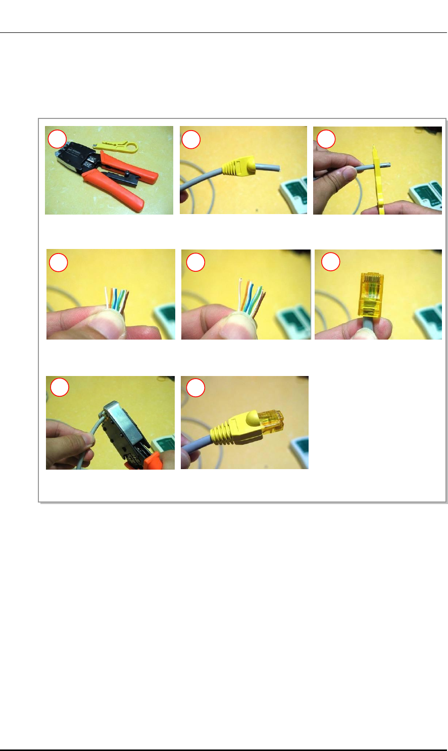
Figure C.3 Assembling the RJ-45 Connector (Normal Type)
1) Prepare work tools and
materials.
2) Insert the RJ-45 cap to the
cable.
3) Remove the coating 0.67 in.
(17 mm) from the end.
4) Arrange the cable in reference
to the pin map.
5) Cut the cable to make it
0.47 in. (12 mm) long.
1
2
3
4
5
6
7
8
7) Compress the jack using the
tool.
6) Insert the cable completely
into the RJ-45 modular jack.
8) Push the RJ-45 cap to the
connector.
Ver.
ANNEX C. Connector Assembly
C-4 © SAMSUNG Electronics Co., Ltd.
2600-00F1W8GAA
4.0
C.3 N type-male (LMR-400)
Below is the procedure for assembling the N type-male cable connector to LMR-400 cable.
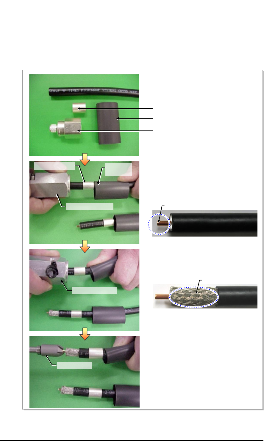
Figure C.4 N type-male Connector Assembling (1)
in.B
in.
케이블 랙
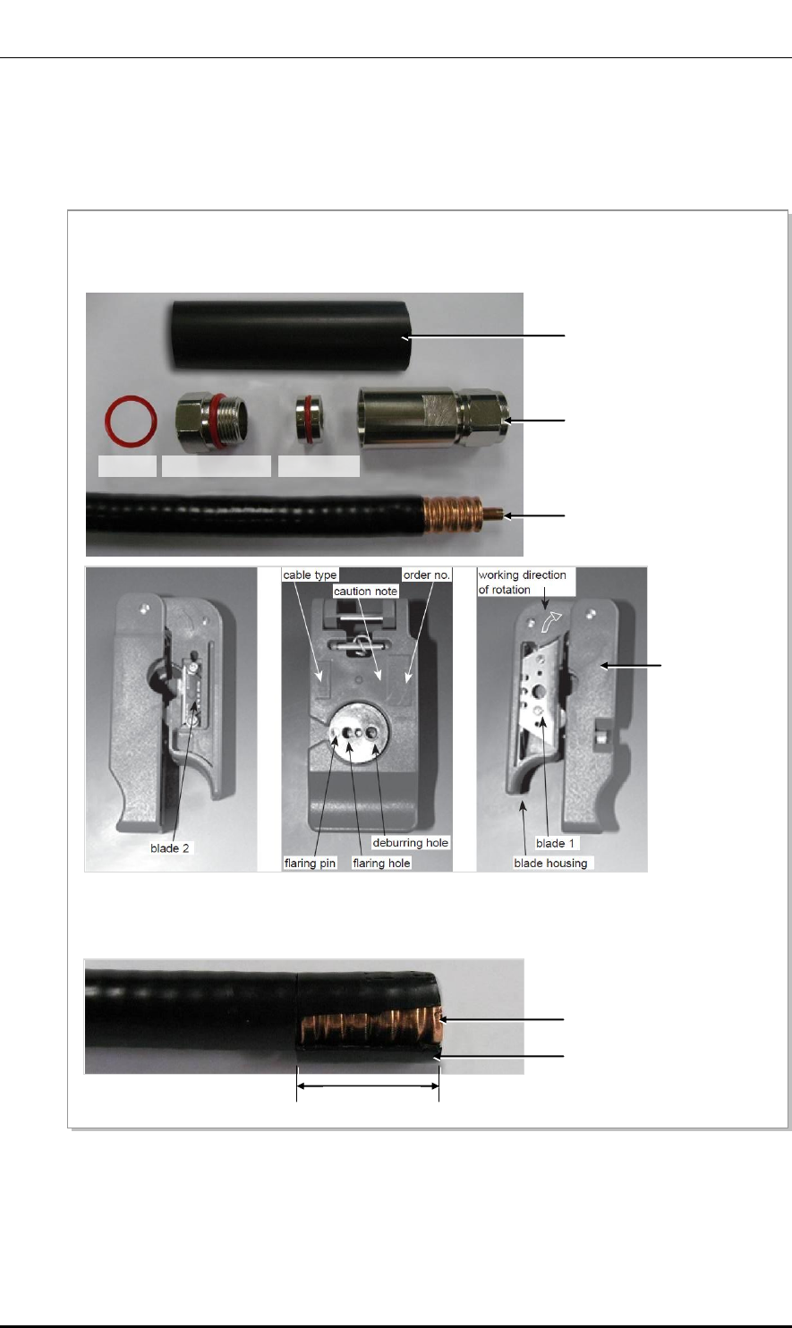
1) The components of the N type-male include
N type-male body, clamp ring, and heat shrink
tube.
2) Insert a heat shrink tube and clamp ring to the
cable, and insert the cable into the ‘End1’ of the
prep/strip tool. Then remove the shield and sheath
except for the center conductor at the end of cable
by rotating the tool clockwise.
3) Insert the cable into the ‘End2’ of the prep/strip tool
again, and remove the sheath except for the shield
by rotating the tool.
4) Trim the end of the center conductor by using a
deburring tool.
Heat Shrink Tube
Clamp Ring
N type-Male Body
LMR-400
LMR-400
Prep/strip Tool End1
Prep/strip Tool End2
Deburring tool
Center Conductor
Shield
Clamp Ring
Heat Shrink
Tube
Ver.
Mobile WiMAX/TD-LTE Smart MBS, U-RAS Flexible V2 RRH-B4 Installation Manual
© SAMSUNG Electronics Co., Ltd. C-5
2600-00F1W8GAA
4.0
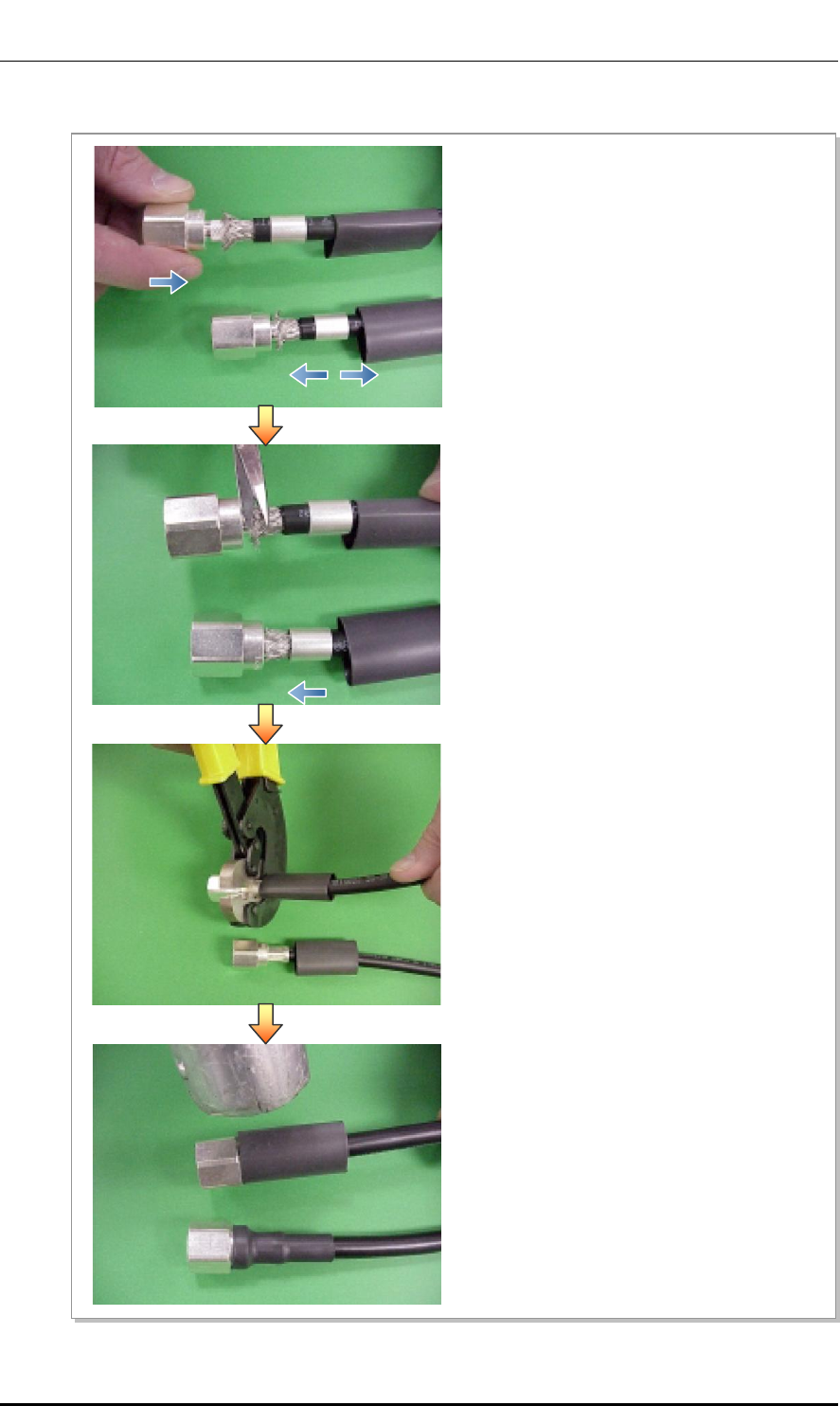
Figure C.5 N type-male Connector Assembling (2)
in.B
in.
케이블 랙
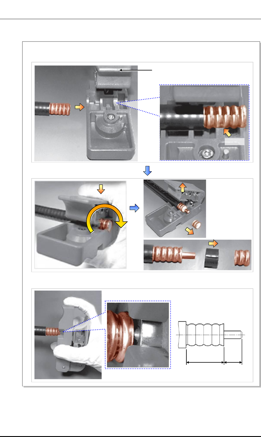
5) Push a connector into the end of the cable.
Then, push it further until the center conductor is
firmly inserted into the pin connection part of the
N-Type male body.
Make the shield overlap the N-Type male body,
pull out the clamp ring, and let it go to its original
position so that the remaining length may be folded.
6) Cut off the folded length of the shield using a
cutting device so that it does not protrude outside
when the clamp ring is inserted.
After arranging the shield, push up the clamp ring
toward the connector until the entire shield is
covered.
7) Using a compressor and hexagonal dies,
pressurize the clamp ring to fix the cable and
connector.
8) Lift the heat shrink tube up to the connection point
on the connector and shrink the heat shrink tube
using a heating gun.
Ver.
ANNEX C. Connector Assembly
C-6 © SAMSUNG Electronics Co., Ltd.
2600-00F1W8GAA
4.0
C.4 TNC-male (LMR-400)
Below is the procedure for assembling the TNC-male cable connector to LMR-400 cable.
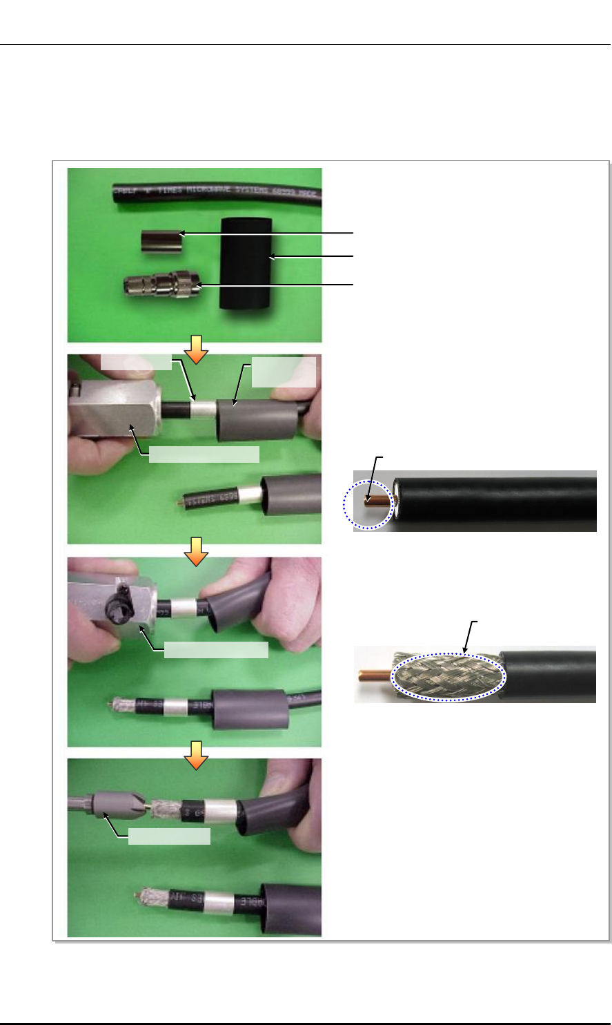
Figure C.6 TNC-male Connector Assembling (1)
1) The components of the TNC-male include TNC-
male body, clamp ring, and heat shrink tube.
2) Insert a heat shrink tube and clamp ring to the
cable, and insert the cable into the ‘End1’ of the
prep/strip tool. Then remove the shield and sheath
except for the center conductor at the end of cable
by rotating the tool clockwise.
3) Insert the cable into the ‘End2’ of the prep/strip tool
again, and remove the sheath by rotating the tool.
4) Trim the end of the center conductor by using a
deburring tool.
Heat Shrink Tube
Clamp Ring
TNC-Male Body
Prep/strip tool End1
Prep/strip tool End2
Deburring tool
Clamp Ring
Heat Shrink
Tube
LMR-400
Center Conductor
LMR-400
Shield
Ver.
Mobile WiMAX/TD-LTE Smart MBS, U-RAS Flexible V2 RRH-B4 Installation Manual
© SAMSUNG Electronics Co., Ltd. C-7
2600-00F1W8GAA
4.0
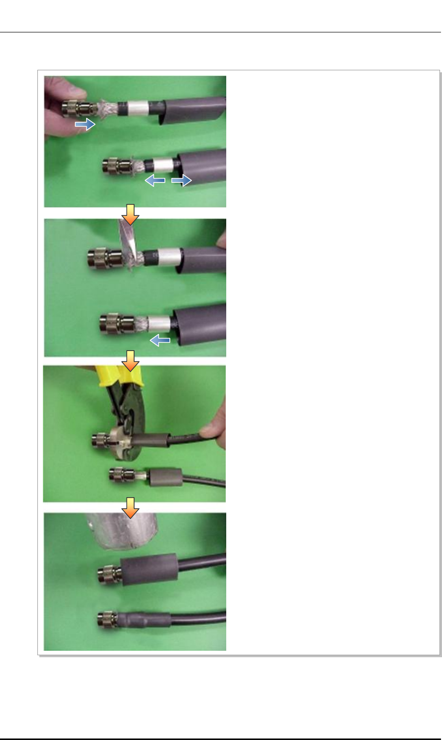
Figure C.7 TNC-male Connector Assembling (2)
5) Push a connector into the end of the cable.
Then, push it further until the center conductor is
firmly inserted into the pin connection part of the
N-Type male body.
Make the shield overlap the N-Type male body, pull
out the clamp ring, and let it go to its original
position so that the remaining len1/2 in. be folded.
6) Cut off the folded length of the shield using a
cutting device so that it does not protrude outside
when the clamp ring is inserted.
After arranging the shield, push up the clamp ring
toward the connector until the entire shield is
covered.
7) Using a compressor and hexagonal dies,
pressurize the clamp ring to fix the cable and
connector.
8) Lift the heat shrink tube up to the connection point
on the connector and shrink the heat shrink tube
using a heating gun.
Ver.
ANNEX C. Connector Assembly
C-8 © SAMSUNG Electronics Co., Ltd.
2600-00F1W8GAA
4.0
C.5 N type-male (1/2 in. feeder line)
Below is the method for assembling the N type-male connector to the 1/2 in. feeder line.
Figure C.8 Assembling the N type-male (1/2 in. Feeder Line) Connector (1)
1) The components of the N type-male are an N type-male body, an insert ring, a clamping nut, O-ring, and a heat
shrink tube, and it is assembled using the wire stripper, trimming tool, spanner, etc.
2) Using a stripping tool or a knife, strip the 1/2 in. feeder line by 1 in. (25.4 mm) from the end, as shown in the
figure below.
Trimming Tool
Heat Shrink Tube
[1.1 in. (28 mm)]
Insert Ring
N type-Male Body
Clamping Nut
1/2 in. Feeder Line
O-Ring
1 in. (25.4 mm)
1/2 in. Feeder Line Conductor
1/2 in. Feeder Line Jacket
Ver.
Mobile WiMAX/TD-LTE Smart MBS, U-RAS Flexible V2 RRH-B4 Installation Manual
© SAMSUNG Electronics Co., Ltd. C-9
2600-00F1W8GAA
4.0
Figure C.9 Assembling the N type-male (1/2 in. Feeder Line) Connector (2)
Trimming Tool
3) Remove the 0.43 in. (11 mm) of the external conductor end and 0.39 in. (10 mm) of the jacket using a
trimming tool.
Collet
4) Insert the internal conductor into the deburring hole at the bottom of the trimming tool to trim it.
0.94 in.
(24 mm)
0.43 in.
(11 mm)

Ver.
ANNEX C. Connector Assembly
C-10 © SAMSUNG Electronics Co., Ltd.
2600-00F1W8GAA
4.0
Figure C.10 Assembling the N type-male (1/2 in. Feeder Line) Connector (3)
5) Insert the o-ring, clamping nut, insert ring and N type-male body to the stripped 1/2 in. feeder line in
this order. O-ring is inserted into the second groove from inside of outer insulator.
6) Tighten the clamping nut and N type-male body inserted into the 1/2 in. feeder line firmly using a spanner.
The recommended torque for tightening the clamping nut and N type-male body is 306~510 lbf·ft (30~
50 N.m). (Note that it should only be tightened by rotating the external body with the clamping nut in a
fixed and stable position.)
Insert Ring
N type-Male Body
Clamping Nut
O-Ring
Keep the
fixed state
Ver.
Mobile WiMAX/TD-LTE Smart MBS, U-RAS Flexible V2 RRH-B4 Installation Manual
© SAMSUNG Electronics Co., Ltd. C-11
2600-00F1W8GAA
4.0
Figure C.11 Assembling the N type-male (1/2 in. Feeder Line) Connector (4)
Checking to carry out when assembling the N type-male connector
The shape, tool and assembly method may differ depending on the connector
type and manufacturer. Make sure to check the user manual provided by the
manufacturer before assembling.
Clamping Nut
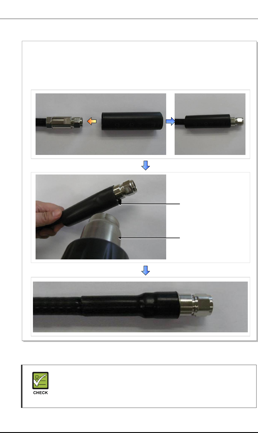
7) Insert the heat shrink tube into the 1/2 in. feeder line fitted with the N type-male connector as shown in the
Figure below.
- Heat shrink tube: Φ 1.1 in., 3.94 in. (Φ 28 mm, 100 mm)
8) Shrink the heat shrink tube inserted into the 1/2 in. feeder line using a heating gun.
Heating Gun
Heat Shrink Tube (1.1 in.)
Ver.
ANNEX C. Connector Assembly
C-12 © SAMSUNG Electronics Co., Ltd.
2600-00F1W8GAA
4.0
C.6 Din type-male (1/2 in. Feeder Line)
Below is the method for assembling the Din type-male connector to the 1/2 in. feeder line.
Figure C.12 Assembling the Din type-male (1/2 in. Feeder Line) Connector (1)
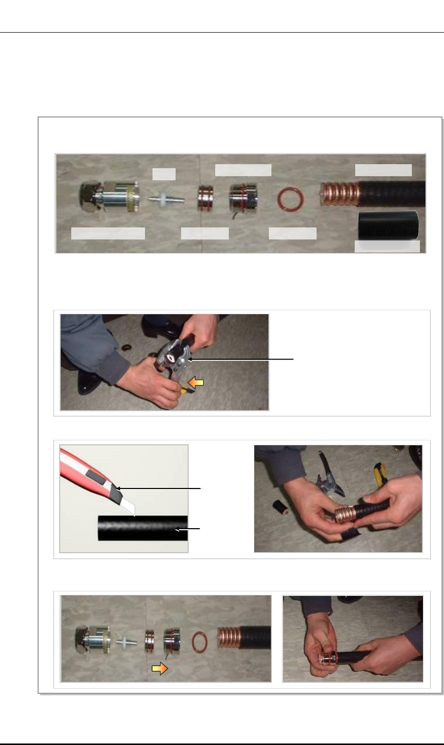
2) Straighten the cable, then, using a suitable tool, strip it to the connector’s wire strip length.
When cutting the sheath, hold the cable firmly with one hand and cut the cable pulling the cutting
tool inwards with the other hand. Gently rotate the tool several times (do not pull it too hard), so that
the internal copper line is not damaged.
3) Using a cutter, cut the sheath from the stripped edge to the end of the cable and completely strip the sheath.
Cutting Tool
Cutter
Feeder Line
1) The components of the Din type-male are an Din type-male body, pin, an insert ring, a clamping nut,
o-ring, and a heat shrink tube, and it is assembled using the wire stripper, trimming tool, wrench, etc.
4) Insert the o-ring, clamping nut, insert ring, pin and Din type-male body into the stripped feeder line in
this order.
Din Type-Male Body
Pin
Insert Ring
Clamping Nut
O-Ring
Feeder Line
Heat Shrink Tube
Ver.
Mobile WiMAX/TD-LTE Smart MBS, U-RAS Flexible V2 RRH-B4 Installation Manual
© SAMSUNG Electronics Co., Ltd. C-13
2600-00F1W8GAA
4.0
Figure C.13 Assembling the Din type-male (1/2 in. Feeder Line) Connector (2)
Checking to carry out when assembling the Din type-male connector
The shape, tool and assembly method may differ depending on the connector
type and manufacturer. Make sure to check the user manual provided by the
manufacturer before assembling.
Spanner (keep the fixed state)
5) Tighten firmly the clamping nut and Din type-male body inserted to the 1/2 in. feeder line using a wrench.
The recommended torque for tightening the clamping nut and Din type-male body is 30~50 N.m.
(Note that it should only be tightened by rotating the external body with the clamping nut in a fixed and
stable position.)
Clamping Nut
6) Insert the heat shrink tube to the 1/2 in. feeder line fitted with the Din type-male connector; and shrink the
heat shrink tube inserted into the feeder line using a heating gun.
- Heat shrink tube: Φ 1.1 in., 3.94 in. (Φ 28 mm, 100 mm)
Heating Gun
Heat Shrink Tube
Din Type-Male Body
Ver.
ANNEX C. Connector Assembly
C-14 © SAMSUNG Electronics Co., Ltd.
2600-00F1W8GAA
4.0
C.7 Finishing the Connector Connection Part by
Tape
Finishing the connector connection part by tape (insulation tape, rubber tape, etc.) in the
outdoor environment is as follows:
Figure C.14 Finishing the Connector Connection Part by Tape
Cable Tie
Rubber Tape
Insulation
Tape
1) Overlap the exposed part of the connector connection part using rubber tape (Keep a distance as the
half size of rubber tape) and press it with your hands lightly to make rubber tape adhere well.
2) Wrap the part where the rubber tape is attached using insulation tape two times or more. When cutting
off the tape, cut it off neatly using a cutting device such as scissors or a knife.
3) Bind the end part of the insulation tape using cable tie to prevent slips.

Ver.
Mobile WiMAX/TD-LTE Smart MBS, U-RAS Flexible V2 RRH-B4 Installation Manual
© SAMSUNG Electronics Co., Ltd. C-15
2600-00F1W8GAA
4.0
C.8 How to Shrink the Heat Shrink Tube
C.8.1 When Assembling a Connector to the Feeder Line
Below is the procedure for shrinking the heat shrink tube.
Figure C.15 Shrinking the Heat Shrink Tube_Feeder Line (1)
1) Prepare a 1/2 in. feeder line, heat shrink tube, and
heating gun to finish the cable using a heat shrink
tube.
2) Insert the heat shrink tube into the 1/2 in. feeder
line, and then place the heat shrink tube at the end
of the cutting area of the connector where the tool
will be used.
3) Set the heating gun to 482 to 572°F (250 to 300°C).
Heat Shrink Tube (Jelly Type)
28/6 × 5.9 in. (150 mm)
1/2 in. Connector
Heating Gun
1/2 in. Feeder Line
Cutting Area
Ver.
ANNEX C. Connector Assembly
C-16 © SAMSUNG Electronics Co., Ltd.
2600-00F1W8GAA
4.0
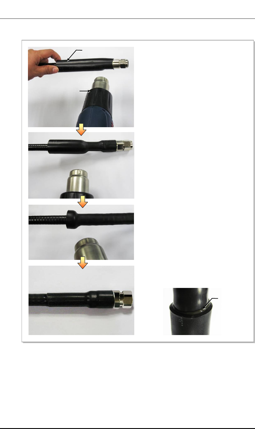
Figure C.16 Shrinking the Heat Shrink Tube_Feeder Line (2)
6) Shrink the heat shrink tube until jelly appears at the
end part of it (refer the Figure below) and finish it.
4) Holding one end of the heat shrink tube with your
hand, apply heat starting from the connector using
the heating gun.
5) Rotate the heating gun so that heat is evenly
distributed to prevent that bubbles are generated or
heat is concentrated to a specific part.
Heat Shrink Tube
Heating Gun
Jelly

Ver.
Mobile WiMAX/TD-LTE Smart MBS, U-RAS Flexible V2 RRH-B4 Installation Manual
© SAMSUNG Electronics Co., Ltd. C-17
2600-00F1W8GAA
4.0
C.8.2 When Connecting a Connector to another Connector
Below is the procedure for shrinking the heat shrink tube.
Figure C.17 Shrinking the Heat Shrink Tube_Connection between Connectors (1)
1) Prepare a 1/2 in. feeder line, 7/8 in. feeder line,
heat shrink tube, and heating gun to finish the
cable using a heat shrink tube.
3) Insert the heat shrink tube, placing connector part
(where 1/2 in. and 7/8 in. feeder line will be connected)
in the center, and mark the center part.
Heat Shrink Tube (Jelly Type)
38/12 × 11.81 in. (300 mm)
7/8 in. Feeder Line
Connector
1/2 in. Feeder Line
Heating Gun
2) Inset the heat shrink tube to one end of the feeder
line and connect the connector.
Ver.
ANNEX C. Connector Assembly
C-18 © SAMSUNG Electronics Co., Ltd.
2600-00F1W8GAA
4.0
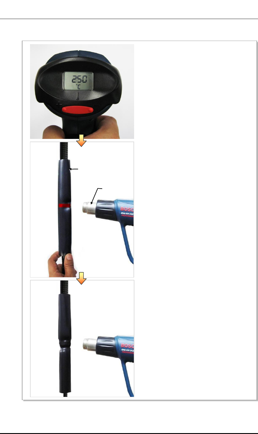
Figure C.18 Shrinking the Heat Shrink Tube_Connection between Connectors (2)
4) Set the heating gun to 482 to 572°F (250 to 300°C).
5) Holding one end of the heat shrink tube with your
hand, apply heat starting from the marked part at
the center using the heating gun.
6) Rotate the heating gun so that heat is evenly
distributed to prevent that bubbles are generated
or heat is concentrated to a specific part.
Heat Shrink Tube
Heating Gun
Ver.
Mobile WiMAX/TD-LTE Smart MBS, U-RAS Flexible V2 RRH-B4 Installation Manual
© SAMSUNG Electronics Co., Ltd. C-19
2600-00F1W8GAA
4.0
Figure C.19 Shrinking the Heat Shrink Tube_Connection between Connectors (3)
7) Shrink the heat shrink tube until jelly appears at
the end part of it (refer the figure below) and
finish it.
Jelly
Ver.
ANNEX C. Connector Assembly
C-20 © SAMSUNG Electronics Co., Ltd.
2600-00F1W8GAA
4.0
Check for Working with the Heat Shrink Tube
- If you work without holding one end of the heat shrink tube, the location of the
heat shrink tube may be changed. Therefore, make sure to hold one end of it
when applying heat.
- The connector part where 1/2 in. and 7/8 in. feeder line are connected must be
the center of the heat shrink tube. After inserting the heat shrink tube, mark the
center part.
- If jelly does not appear on the end of the heat shrink tube, it may mean that it is
not shrunk properly. Apply heat until jelly appears using a heating gun.
Jelly
Ver.
Mobile WiMAX/TD-LTE Smart MBS, U-RAS Flexible V2 RRH-B4 Installation Manual
© SAMSUNG Electronics Co., Ltd. D-1
2600-00F1W8GAA
4.0
ANNEX D. Cleaning Optic Connector
D.1 Cleaning Optic Connector
When connecting optical cable to the system, performance of system can be decreased or
fails can occur if core section of optical connector is dirty due to dust or foreign material.
Therefore, worker should clean the optic connector before connecting optic cable to the
system to prevent this phenomenon.
This manual describes the method that cleans optic connector when using the IBCTM Brand
cleaner.
Caution When Connecting the Optical Cable
Check whether there is dust or foreign material on the cutting section of the
connector core before connecting the optic cable, and keep this away from dust
or foreign material.
If the cable is soiled with foreign material, do not blow to remove them. Make sure
to clean the connector in accordance with the cleaning directions below.
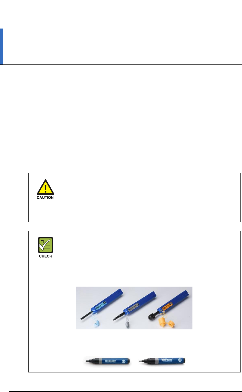
When using Optic Connector Cleaner
When using optic connector cleaner, use the products shown in the example
below or their equivalents.
Ex) Manufacturer-USCONEC (http://www.usconec.com)
- IBCTM Brand Cleaner (P/N: 9393): For LC-LC and MU Connector Cleaning
- IBCTM Brand Cleaner (P/N: 9392): For SC Connector Cleaning
- IBCTM Brand Cleaner (P/N: 12910): For ODC Connector Cleaning
Manufacturer-TheFibers (www.thefibers.com)
- HuxCleaner 1.25 mm Type: For LC and MU Connector Cleaning
- HuxCleaner 2.5 mm Type: For SC, FC and ST Connector Cleaning
Ver.
ANNEX D. Cleaning Optic Connector
D-2 © SAMSUNG Electronics Co., Ltd.
2600-00F1W8GAA
4.0
D.2 IBCTM Brand Cleaner
Method that uses IBCTM Brand Cleaner is as follows:
D.2.1 IBCTM Brand Type Cleaner (P/N 9393)
Method that uses IBCTM Brand Cleaner for LC-LC and MU connector is as follows:
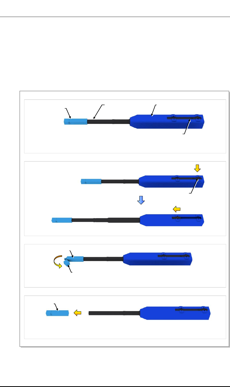
Figure D.1 Optic Connector Cleaner (IBCTM Brand Type Cleaner: P/N 9393)
Outer Shell
[Optic Connector Cleaner Configuration]
Nozzle
Guide Cap
Lock Button
(for Extend Nozzle)
[Nozzle Extension]
[In Case of LC type Connector (Plug)]
Guide Cap
Guide Cap Cover
[In Case of LC type Connector (Jack)]
Guide Cap
Lock Button
(for Extend Nozzle)
Ver.
Mobile WiMAX/TD-LTE Smart MBS, U-RAS Flexible V2 RRH-B4 Installation Manual
© SAMSUNG Electronics Co., Ltd. D-3
2600-00F1W8GAA
4.0
Optic Module Cleaning (LC Type Jack)
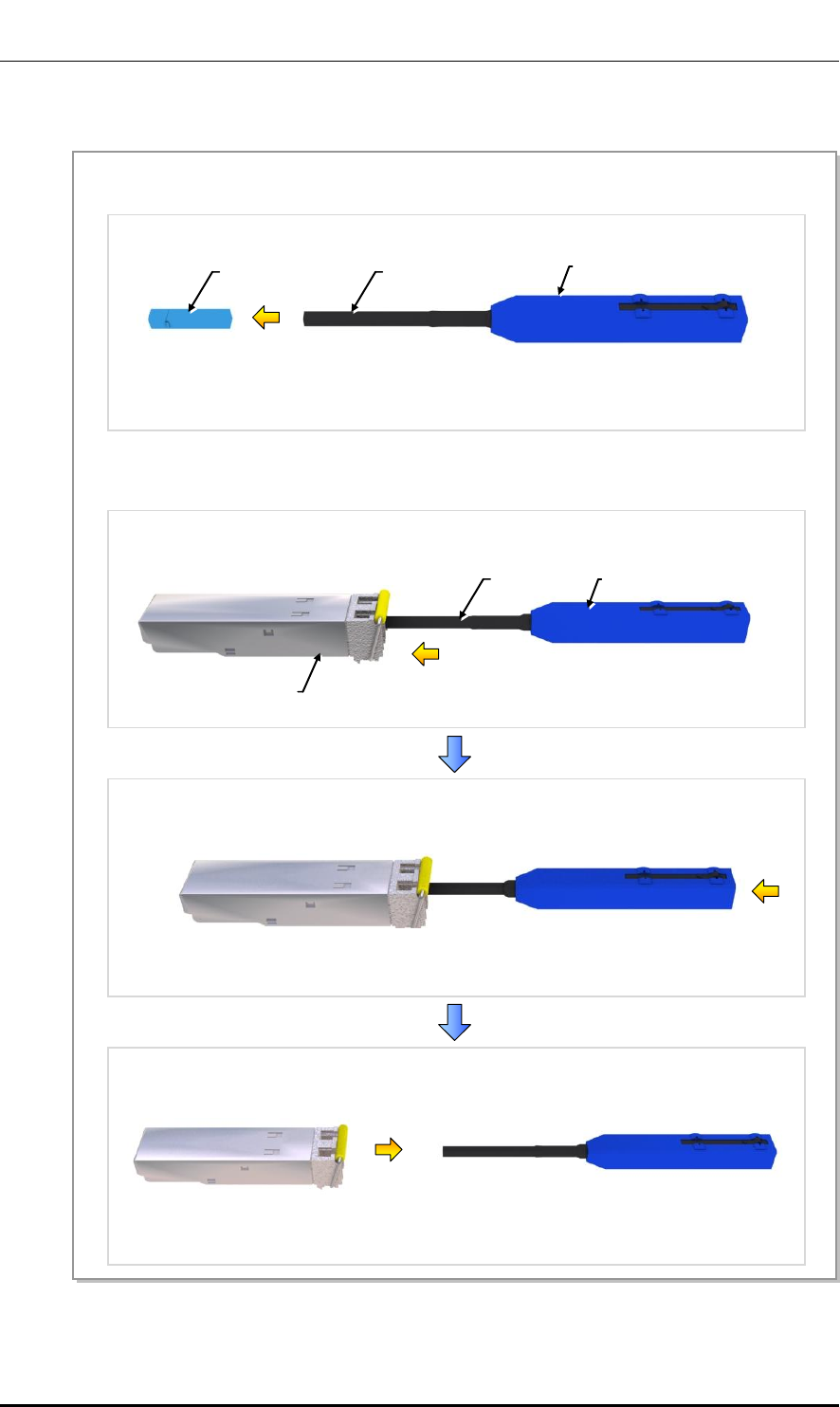
Figure D.2 Optic Module Cleaning (LC Type Jack)
Guide Cap
1) To clean the optic module, remove the guide cap from the cleaner (P/N: 9393).
2) Insert a cleaner guide cap to every core of the optic module. Clean it by pushing the outer shell
toward the nozzle until you hear the sound of the detergent being sprayed. (Repeat once or twice.)
Outer Shell
Nozzle
Nozzle
Outer Shell
Optic Module
[IBC Brand Cleaner: P/N 9393]
Ver.
ANNEX D. Cleaning Optic Connector
D-4 © SAMSUNG Electronics Co., Ltd.
2600-00F1W8GAA
4.0
Optic Cable Connector Cleaning (LC Type Plug)
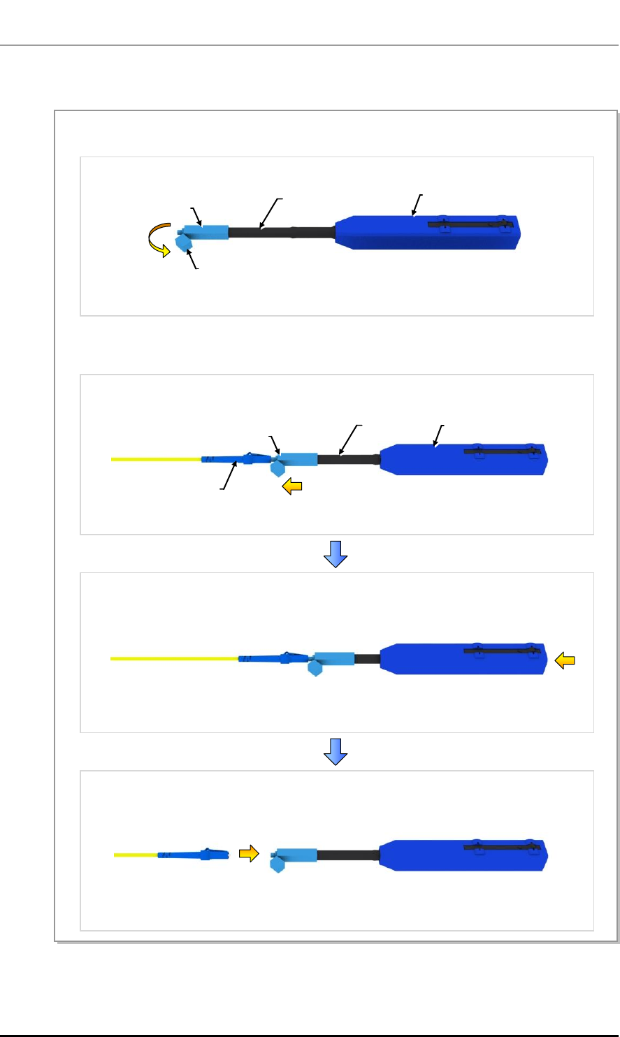
Figure D.3 Optic Cable Connector Cleaning (LC Type Plug)
Guide Cap
Guide Cap Cover
1) To clean the optic cable connector, open the guide cap cover from the cleaner (P/N: 9393).
2) Insert a cleaner guide cap to every core of the optic cable connector. Clean it by pushing the outer shell
toward the nozzle until you hear the sound of the detergent being sprayed. (Repeat once or twice.)
Outer Shell
Nozzle
Guide Cap
Nozzle
Outer Shell
LC Type Connector
[IBC Brand Cleaner: P/N 9393]

Ver.
Mobile WiMAX/TD-LTE Smart MBS, U-RAS Flexible V2 RRH-B4 Installation Manual
© SAMSUNG Electronics Co., Ltd. D-5
2600-00F1W8GAA
4.0
Measuring the Optical Output and Connecting the Optic Connector
Figure D.4 Measuring the Optical Output and Connecting the Optic Connector
[Optic Powermeter]
1) Check the optical output again using an optic power meter.
2) If the optical output measurement result meets the reference value, clean the connector again and
connect it. If the measurement result does not meet the reference value, discard the cable, replace it
with a new cable, and then clean the new one and connect it to the system.
[LC/PC Plug]

Ver.
ANNEX D. Cleaning Optic Connector
D-6 © SAMSUNG Electronics Co., Ltd.
2600-00F1W8GAA
4.0
This page is intentionally left blank.
Ver.
Mobile WiMAX/TD-LTE Smart MBS, U-RAS Flexible V2 RRH-B4 Installation Manual
© SAMSUNG Electronics Co., Ltd. E-1
2600-00F1W8GAA
4.0
ANNEX E. Cable Gland Assembly
Caution When Assembling Cable Gland
If the parts of a cable gland in the system are not correctly installed, outdoor air
and moisture may flow into the system and cause corrosion, system fault, or
serious fault to the cooling system. Therefore, assemble and finish the cable
gland accurately.
Caution When Installing Cable in the Cable Gland
Only one cable of permitted specification (thickness) should be installed in the
cable gland.
- The outdoor air or moisture may flow into the system if a cable that is thinner
than the specification is used.
- If a cable is thicker than the specification or more than two cables are installed,
the cable gland may be damaged.
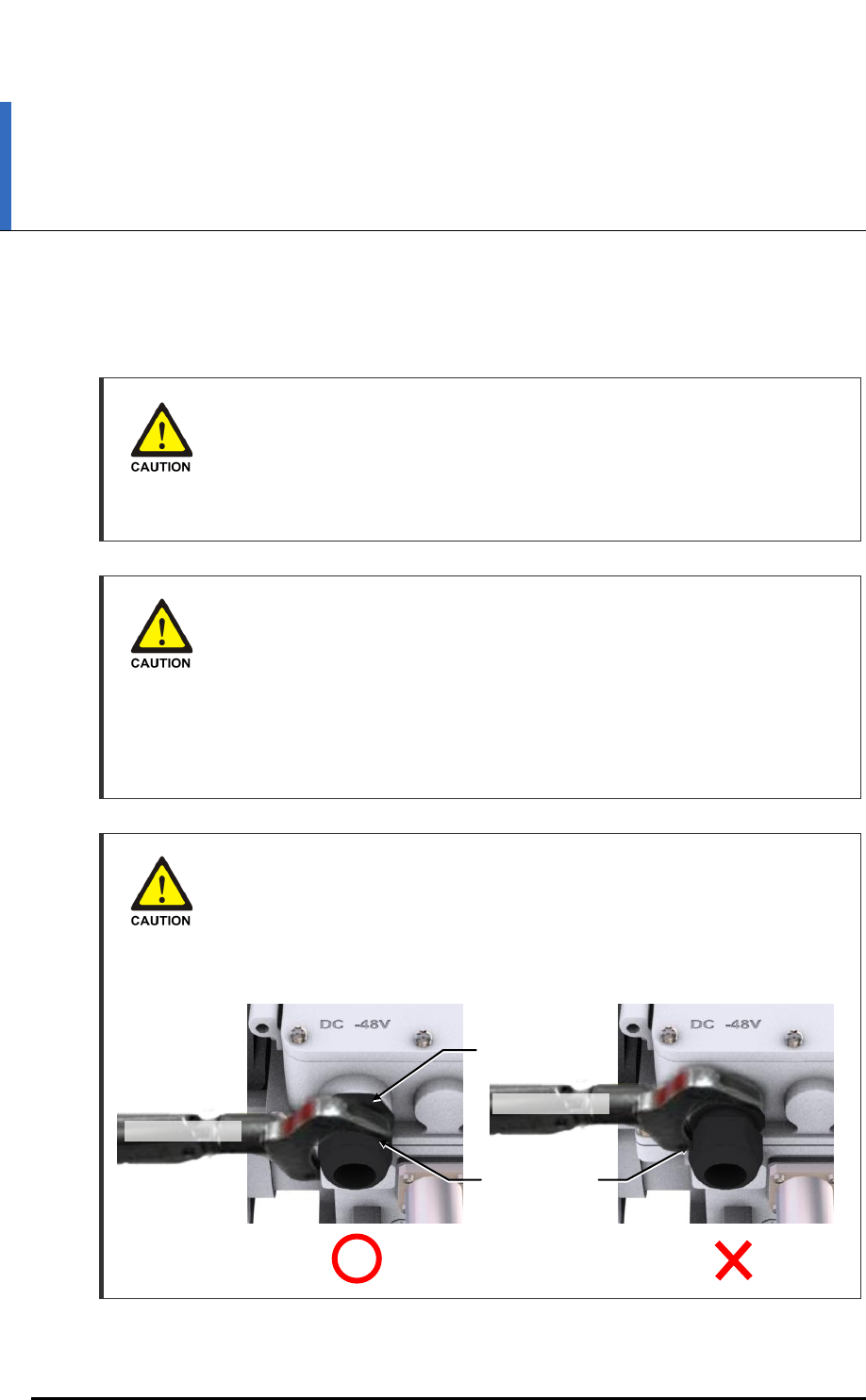
Caution When Loosening or Tightening Cable Gland Nut
When assembling the cable gland or connecting it to a cable, make sure not to
turn other parts (cable gland body) than a gland nut to loosen or tighten the gland.
Turning the cable gland body may cause the influx of external air or moisture into
the system, which may result in corrosion or system malfunction.
Cable Gland Nut
Cable Gland Body
Torque Wrench
Torque Wrench
Ver.
ANNEX E. Cable Gland Assembly
E-2 © SAMSUNG Electronics Co., Ltd.
2600-00F1W8GAA
4.0
Use Torque Wrench When Tightening Cable Gland Nut
Tighten the cable gland nut using a torque wrench with standard torque.
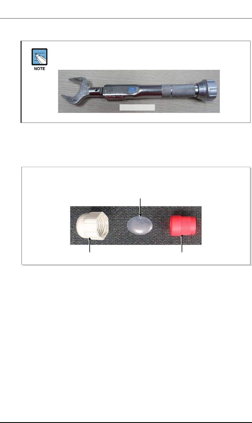
E.1 Cable Gland Components
The components of the cable gland are as follows.
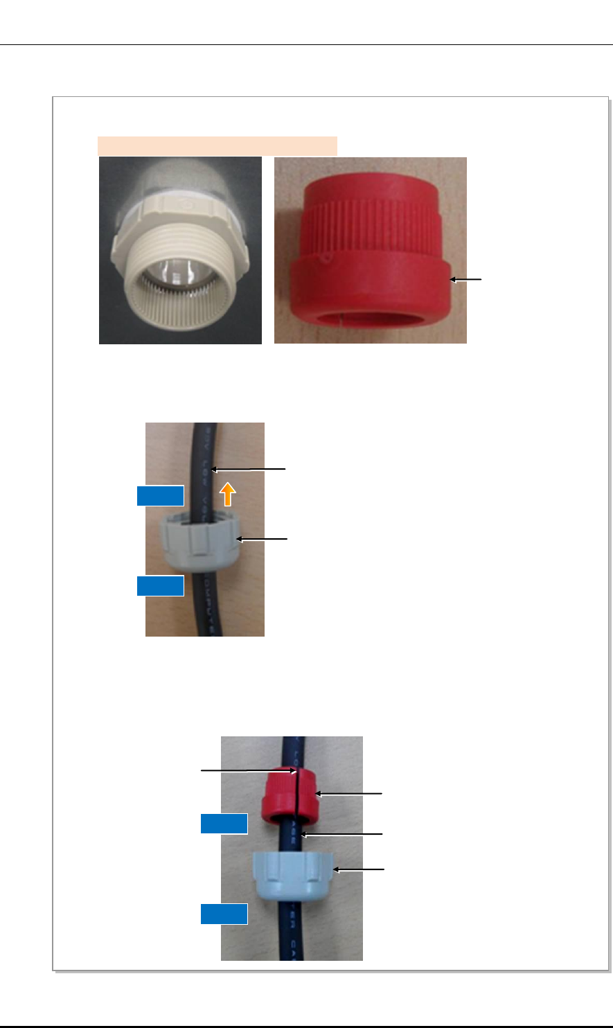
Figure E.1 Cable Gland Components
By loosening the gland nuts outside the unit, the cable gland is dissembled into 3 parts as shown in the
picture below. (Except for system-side fixing parts)
Protection Cover
Cable Gland Nut
Rain-proof Filler
Torque Wrench

Ver.
Mobile WiMAX/TD-LTE Smart MBS, U-RAS Flexible V2 RRH-B4 Installation Manual
© SAMSUNG Electronics Co., Ltd. E-3
2600-00F1W8GAA
4.0
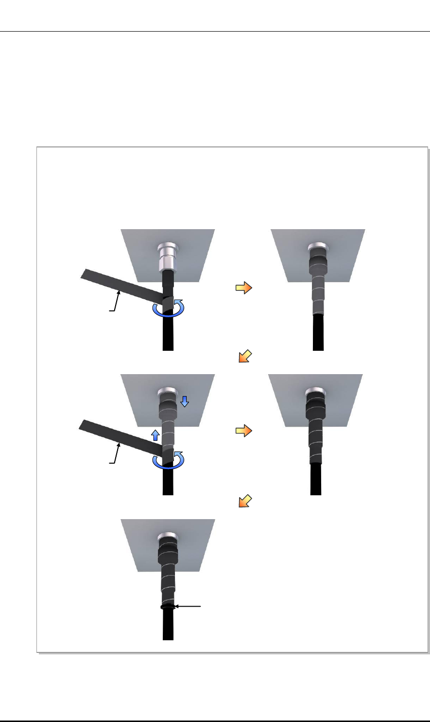
E.2 Cable Gland Assembly and Cabling
When assembling a cable gland, follow the below steps to prevent any moisture or foreign
substance from coming in.
Figure E.2 Cable Gland Assembly and Cabling (1)
1) Check the cable gland built on the unit to see whether it has the protection cover inside the cable
gland nut as shown in the picture below (cross-section picture of outer wall of the unit), the same as
the original factory configuration.
3) Remove the protection cover and keep it carefully.
[Side picture]
Protection Cover
Cable Gland Nut
2) Separate the cable gland nut by loosening counterclockwise. Here, check the protection cover
(circular transparent plate).
Protection Cover
Cable Gland Nut
[When a cable gland nut is disassembled]
Protection Cover
[When the protection cover is removed]
Ver.
ANNEX E. Cable Gland Assembly
E-4 © SAMSUNG Electronics Co., Ltd.
2600-00F1W8GAA
4.0
Figure E.3 Cable Gland Assembly and Cabling (2)
4) Separate the waterproof filler from the cable gland body.
6) After installing the cable through the cable gland body, connect it to the system according to
assembling standard and clean up the rest of the cable.
5) Install the cable by passing it through the cable gland nut from outside to inside.
Rain-proof Filler
[When the rainproof filler is disassembled]
Cable Gland Nut
Cable
Inside
Outside
7) Put the rainproof filler on the cable inside the cable gland nut. At this time, widen the waterproof filler
and wrap the cable around.
Rain-proof Filler
Cable
Cable Gland Nut
Grooves of Rain-proof Filler
Inside
Outside

Ver.
Mobile WiMAX/TD-LTE Smart MBS, U-RAS Flexible V2 RRH-B4 Installation Manual
© SAMSUNG Electronics Co., Ltd. E-5
2600-00F1W8GAA
4.0
Figure E.4 Cable Gland Assembly and Cabling (3)
8) Push the waterproof filler into the cable gland body. There are bumps inside of a cable gland body and
outside of a rainproof filler, which allow easy coupling while preventing slippery rotation. Align the
bumps and push the rainproof filler into the cable gland body.
9) Attach the waterproof filler into the cable gland body as shown in the picture below. Make sure it is
pushed in completely.
Rain-proof Filler
Cable
Cable Gland Nut
Cable Gland Body
Bumps of
Rain-proof
Filler
Rain-proof Filler
Cable Gland Nut
Cable
Cable Gland Body
X
O
10) Attach the cable gland nut and the cable gland body together and tighten the nut clockwise.
Cable Gland Nut
Cable
Cable Gland Body

Ver.
ANNEX E. Cable Gland Assembly
E-6 © SAMSUNG Electronics Co., Ltd.
2600-00F1W8GAA
4.0
E.3 Unused Cable Gland Inspection and Assembly
The unused cable gland should not be disassembled, and be kept in the original factory
configuration.
If the cable gland is disassembled, it should be assembled to the factory default by referring
to the sequence of ‘Cable Gland Parts Configuration’.
Figure E.5 Unused Cable Gland Inspection and Assembly
Checking Assembly State of the Unused Cable Gland
All components of the unused cable gland must be secured in the original factory
configuration. If the cable gland nut is fitted without the waterproof filler or the
protection cover in place, reassemble them as illustrated in ‘Unused Cable Gland
Inspection and Assembly’.
Inside of the
System
Outside of the System
Cable Gland
Washer
Cable Gland Body
Rain-proof
Filler
Protection
Cover
Cable Gland
Nut
System Frame
Ver.
Mobile WiMAX/TD-LTE Smart MBS, U-RAS Flexible V2 RRH-B4 Installation Manual
© SAMSUNG Electronics Co., Ltd. F-1
2600-00F1W8GAA
4.0
ANNEX F. Pressure Terminal
Assembly
F.1 Preparations
The followings must be prepared to connect a pressure terminal to a cable.
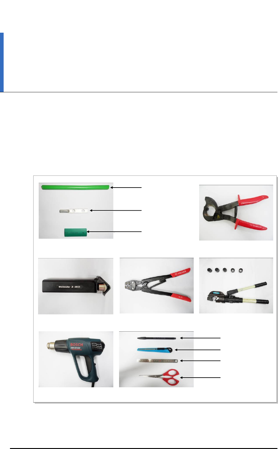
Figure F.1 Preparations
[Cable Cutter]
[Wire Stripper]
[Handheld Compressor]
[Hydraulic Press]
[Heating Gun]
[Marking Pen]
[Cutter Blade]
[Steel Ruler]
[Scissors]
[Cable]
[Pressure Terminal]
[Heat Shrink Tube]
Ver.
ANNEX F. Pressure Terminal Assembly
F-2 © SAMSUNG Electronics Co., Ltd.
2600-00F1W8GAA
4.0
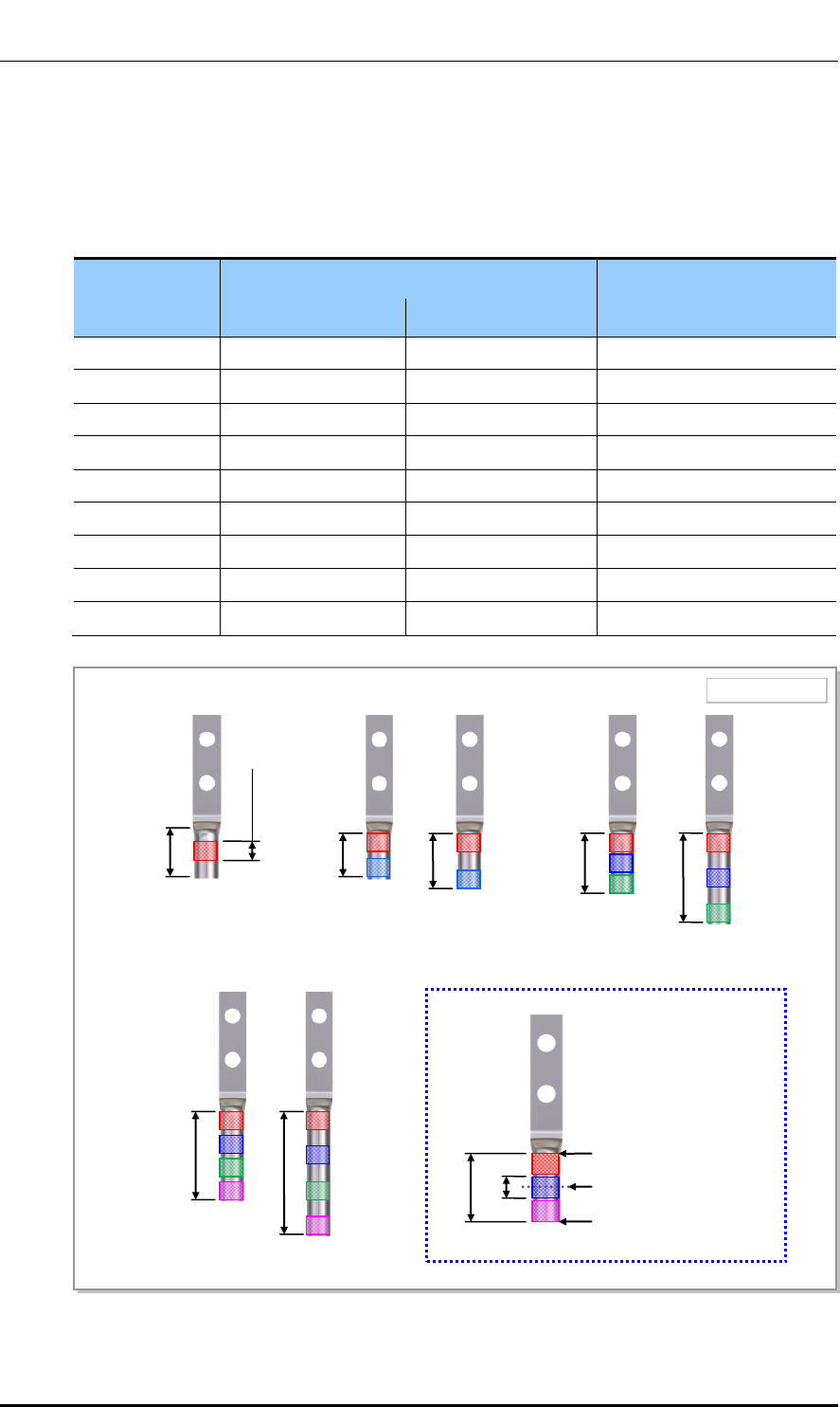
F.2 Pressure Reference Table
The pressure reference table used to assemble a pressure terminal to a cable is shown below.
Table F.1 Pressure Reference Table for Pressure Terminal
Category
Copper tube length of a pressure terminal
Number of pressure points
mm
In.
Hand
11 mm or less
0.43 in.
1
Hand
12~15 mm
0.47~0.59 in.
2
Hand
16~23 mm
0.63~0.91 in.
3
Hand
24~32 mm
0.94~1.26 in.
4
Hand
33 mm or more
1.3 in. or more
5
Hydraulic
30 mm or less
1.18 in. or less
2
Hydraulic
31~47 mm
1.22~1.85 in.
3
Hydraulic
48~63 mm
1.89~2.48 in.
4
Hydraulic
64 mm or more
2.52 in. or more
5
Figure F.2 Pressure Reference Drawing (Handheld Compressor)
[1-spot]
[2-spot]
[3-spot]
[4-spot]
Unit: in. (mm)
0.43 (11)
0.18 (4.5)
0.47 (12)
0.59 (15)
0.63 (16)
0.91 (23)
0.94 in. (24)
1.26 (32)
0.63 (16)
0.18 (4.5)
Copper Tube Starting
Middle of Copper Tube
Arbitrary Fixing
Reference Points
Ver.
Mobile WiMAX/TD-LTE Smart MBS, U-RAS Flexible V2 RRH-B4 Installation Manual
© SAMSUNG Electronics Co., Ltd. F-3
2600-00F1W8GAA
4.0
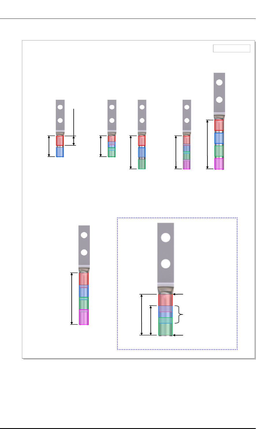
Figure F.3 Pressure Reference Drawing (Hydraulic Press)
Unit: in. (mm)
[2-spot]
[3-spot]
[4-spot]
1.18 (30)
[4-spot]
Copper Tube
Starting
Duplicate Pressure
Arbitrary Fixing
Reference Points
0.53 (13.5)
1.22 (31)
0.53 (13.5)
1.22 (31)
1.85 (47)
1.89 (48)
2.48 (63)
2.52 (64)

Ver.
ANNEX F. Pressure Terminal Assembly
F-4 © SAMSUNG Electronics Co., Ltd.
2600-00F1W8GAA
4.0
Table F.2 Compressor Specifications per Cable Thickness
Cable Size
(mm2)
Press Size
Small Handheld Press
Large Handheld Press
(AK-38, 100)
Hydraulic Press
(IZUMI Hexagonal Dies)
2.5
2
X
X
4
2
X
X
6
5.5
X
X
10
8
8
X
16
14
14
16
25
22
22
25
35
38
38
35
50
X
60
50
70
X
80
70
95
X
100
95~300
Ver.
Mobile WiMAX/TD-LTE Smart MBS, U-RAS Flexible V2 RRH-B4 Installation Manual
© SAMSUNG Electronics Co., Ltd. F-5
2600-00F1W8GAA
4.0
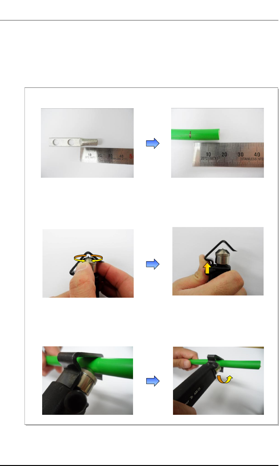
F.3 Assembling Pressure Terminal
The procedures for assembling a pressure terminal to a cable are as follows:
Strip the Cable Sheath
Figure F.4 Stripping Cable Sheath (1)
4) Put a cable into a clamp, locate a blade on a marking position, and push it into the sheath.
5) Align the stripper to be perpendicular to the cable and rotate it more than two laps.
1) After checking the inside length of a pressure terminal, mark the cable.
2) Adjust the length of a cutter blade according to the sheath thickness of the cable.
3) Push the clamp with a thumb a ccording to the cable size to secure a space for the cable.
Ver.
ANNEX F. Pressure Terminal Assembly
F-6 © SAMSUNG Electronics Co., Ltd.
2600-00F1W8GAA
4.0
Figure F.5 Stripping Cable Sheath (2)
6) Push the lever of the stripper to the right to turn its blade at 90°.
8) Remove the sheath.
7) Move the stripper up to the end of cable while maintaining the stripper to be perpendicular to the cable.
Ver.
Mobile WiMAX/TD-LTE Smart MBS, U-RAS Flexible V2 RRH-B4 Installation Manual
© SAMSUNG Electronics Co., Ltd. F-7
2600-00F1W8GAA
4.0
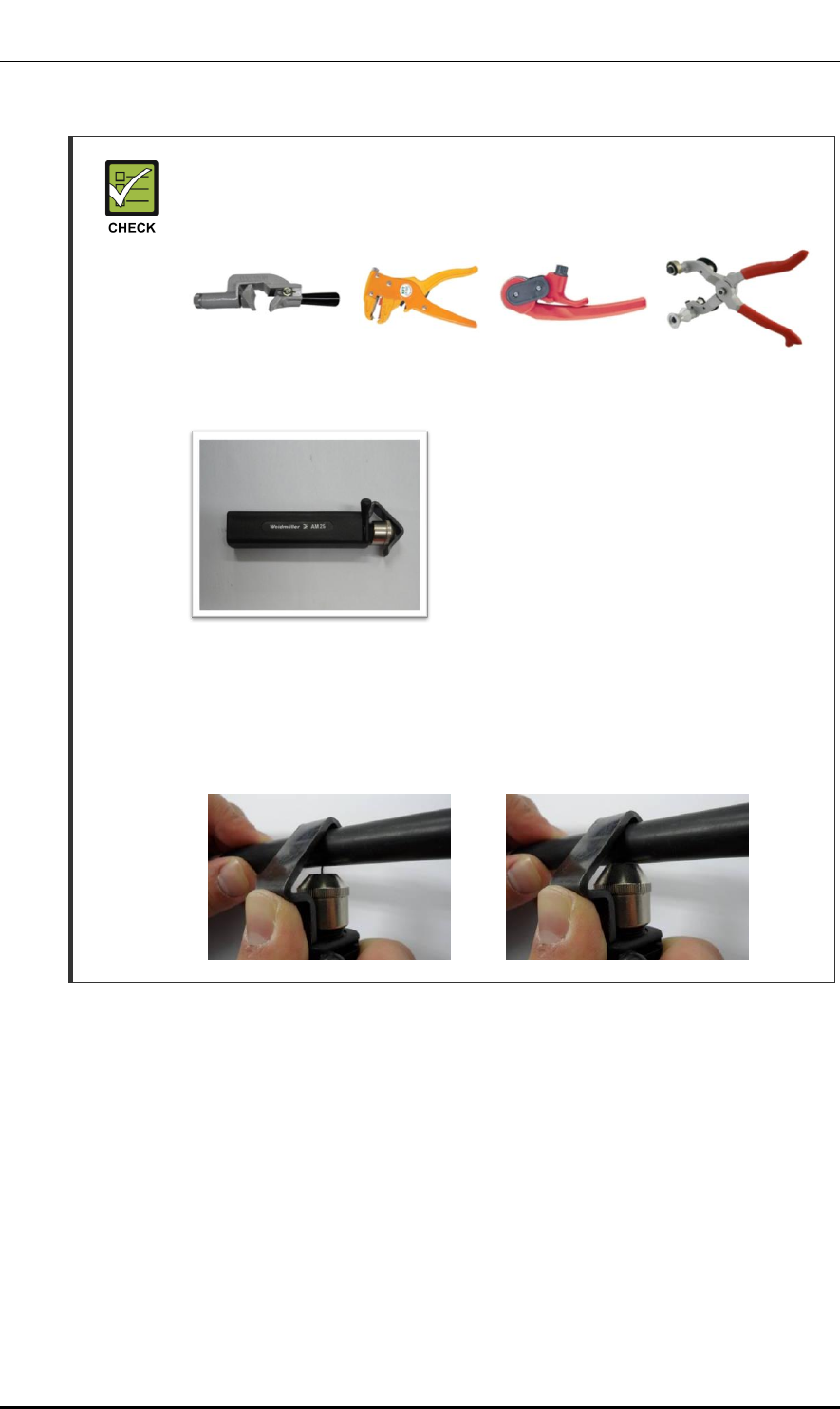
Checking When Using A Wire Stripper
A wire stripper is used differently depending on its manufacturer or type.
Therefore, refer to the user manual enclosed with the product.
The specifications and cautions of a wire stripper described in this manual are as
follows:
Vender: Weidmuller
Model: Weidmuller-AM25 (Order No-
9001080000)
Specifications: For outer diameter 0.24~0.94 in.
(6~24 mm) PVC clothing Up to 4.5 mm
clothing cutting depth
- To prevent the cutter blade of a wire stripper from touching the cable conductor,
adjust the length of cutter blade by checking the cable sheath thickness.
- Make sure that the cutter blade goes into the cable sheath completely.
- Rotate the wire stripper perpendicularly to the cable.
[X]
[O]

Ver.
ANNEX F. Pressure Terminal Assembly
F-8 © SAMSUNG Electronics Co., Ltd.
2600-00F1W8GAA
4.0
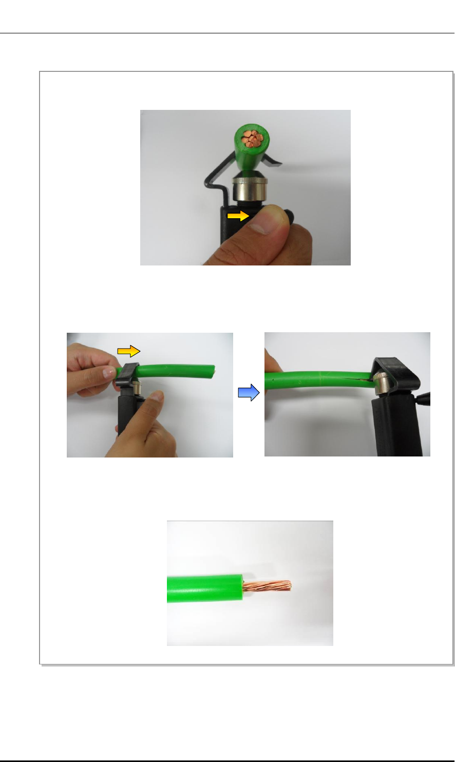
Fixing Pressure Terminal (Handheld Compressor)
Figure F.6 Fixing Pressure Terminal_Handheld Compressor (1)
1) Insert the conductor of the cable with the sheath stripped to the internal end of pressure terminal. For a
ring type pressure terminal, push it in until the conduct comes out 1 mm from the end of the terminal.
2) From the holes of handheld compressor, select one that fits to the pressure terminal.
3) Insert the pressure terminal to the selected hole.
4) Fix the pressure terminal and cable temporarily so the position can be changed later by pressing the
compressor.
Ver.
Mobile WiMAX/TD-LTE Smart MBS, U-RAS Flexible V2 RRH-B4 Installation Manual
© SAMSUNG Electronics Co., Ltd. F-9
2600-00F1W8GAA
4.0
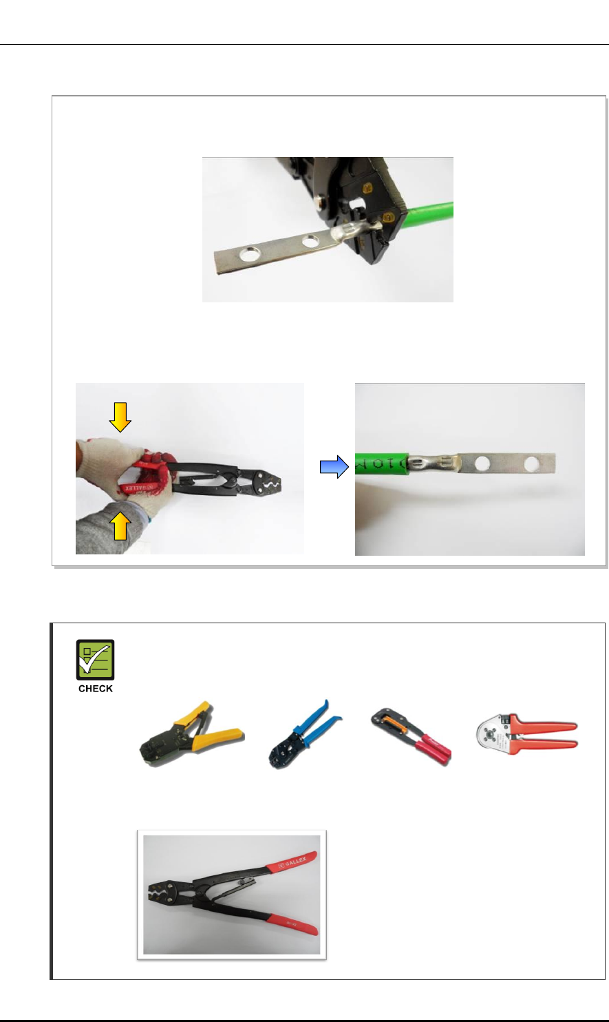
Figure F.7 Fixing Pressure Terminal_Handheld Compressor (2)
Checking When Using A Handheld Compressor
A handheld compressor is used differently depending on its manufacturer or type.
Therefore, refer to the user manual enclosed with the product.
The specifications and cautions of a handheld compressor described in this
manual are as follows:
Vender: GALLEX
Model: GL-2045A-22
Specification: 5.5 mm2, 8 mm2, 14 mm2,
22 mm2 (JIS)
6 mm2, 10 mm2, 16 mm2, 25 mm2 (DIN)
5) After complementary of the cable which is temporary fixed, align it to the hole and firmly compress the
pressure terminal to secure fix it.
6) Separate the pressure terminal from the handheld compressor. Press down the handle of compressor
until a clicking sound is heard to be unlocked.
Ver.
ANNEX F. Pressure Terminal Assembly
F-10 © SAMSUNG Electronics Co., Ltd.
2600-00F1W8GAA
4.0
Fixing Pressure Terminal (Hydraulic Press)
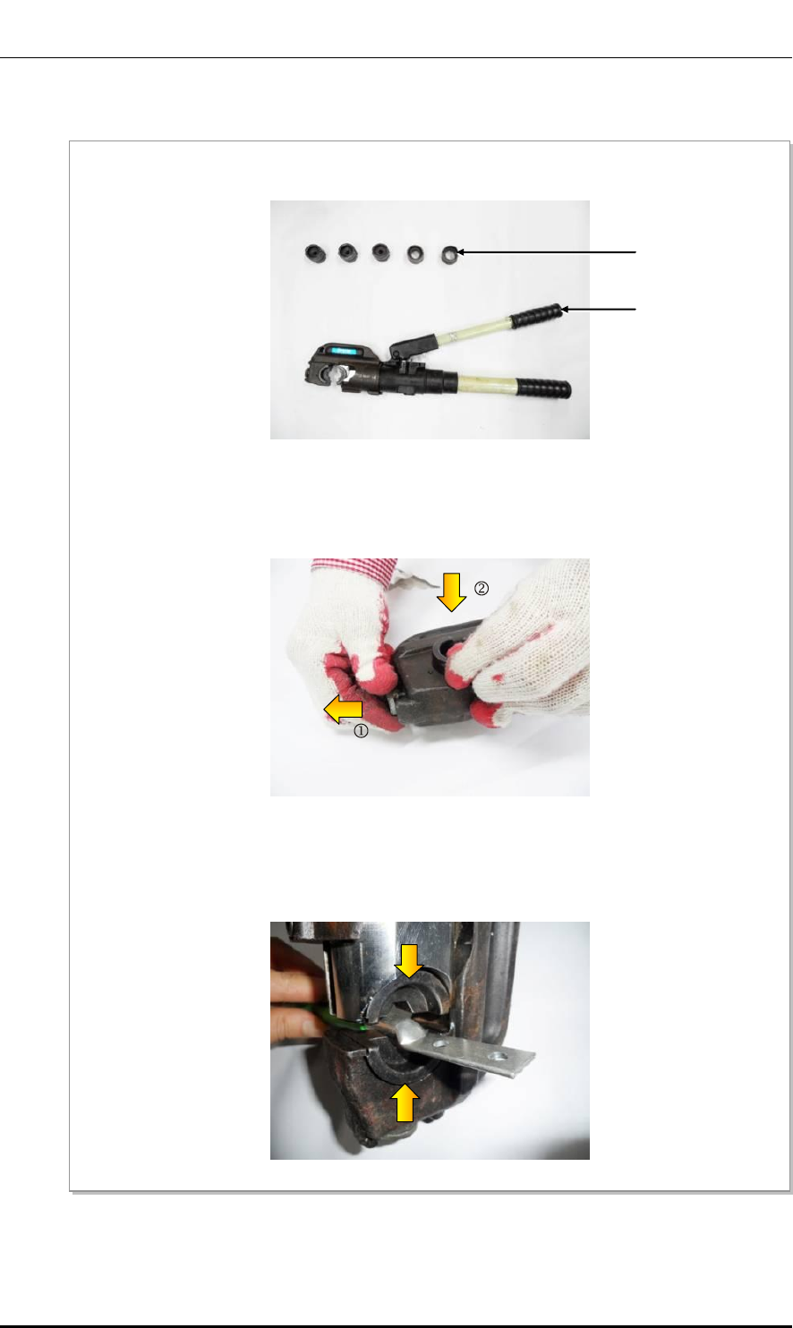
Figure F.8 Fixing Pressure Terminal_Hydraulic Press (1)
1) Among the dies of the hydraulic press, select one that fits to the pressure terminal.
Dies
Hydraulic
Press
2) Assemble the dies to the pressing area of the compressor.
3) Insert the pressure terminal into the pressing area and fix it slightly by aligning it to the end of cable
sheath.
Ver.
Mobile WiMAX/TD-LTE Smart MBS, U-RAS Flexible V2 RRH-B4 Installation Manual
© SAMSUNG Electronics Co., Ltd. F-11
2600-00F1W8GAA
4.0
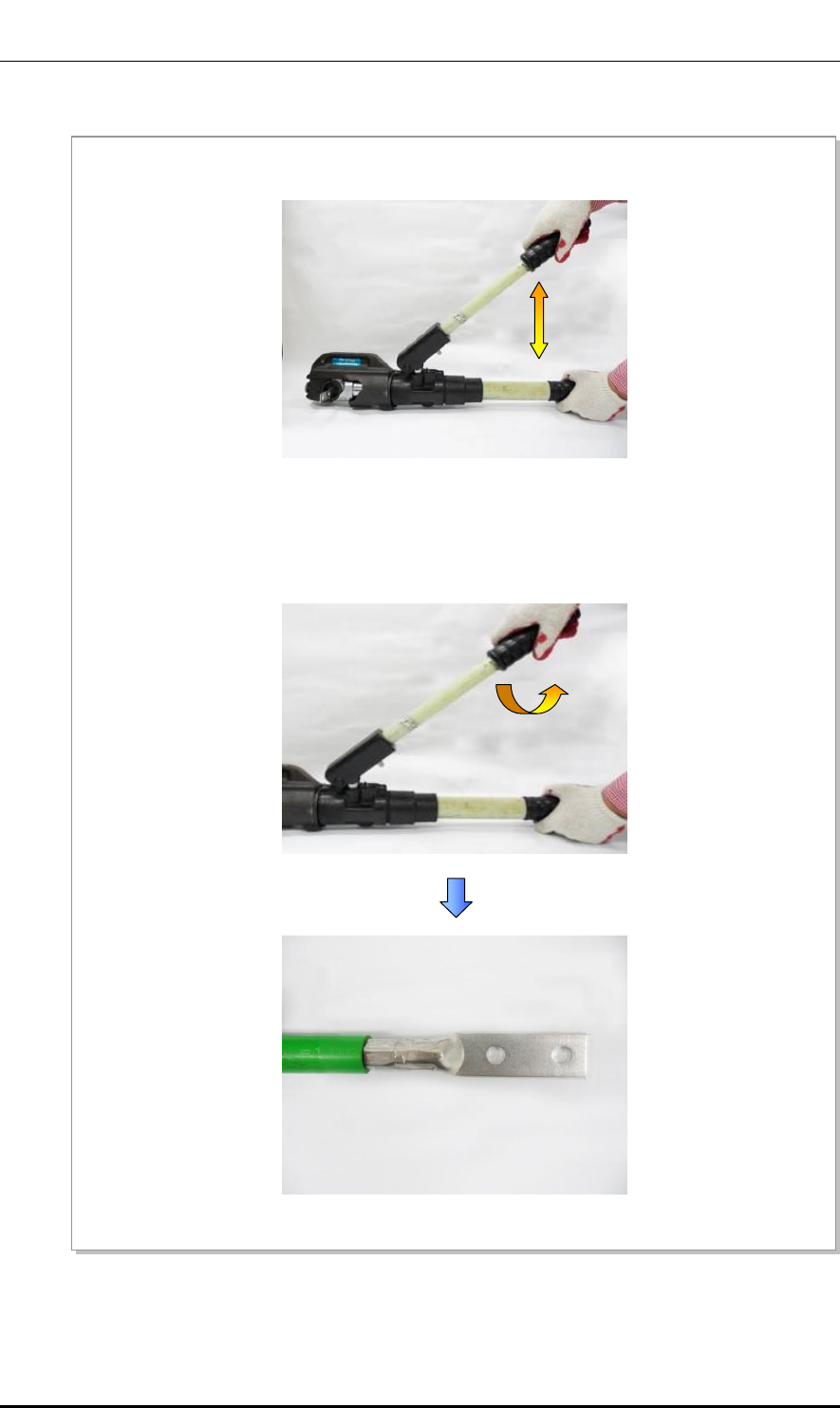
Figure F.9 Fixing Pressure Terminal_Hydraulic Press (2)
4) Move the compressor lever up and down to press the pressure terminal firmly.
5) Turn the top compressing lever clockwise and then push it down. When the pressing area of
compressor is loosened, remove the pressure terminal.
Ver.
ANNEX F. Pressure Terminal Assembly
F-12 © SAMSUNG Electronics Co., Ltd.
2600-00F1W8GAA
4.0
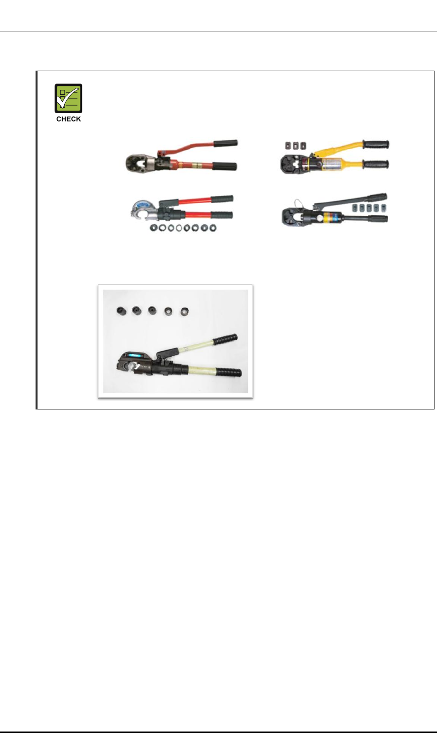
Checking When Using a Hydraulic Press
A hydraulic press is used differently depending on its manufacturer or type.
Therefore, refer to the user manual enclosed with the product.
The specifications and cautions of a hydraulic press described in this manual are
as follows:
Vender: IZUMI
Model: IZUMI-EP-510B
Specification: Circular 32~160 (SQ)
Hex 14~325 (SQ)

Ver.
Mobile WiMAX/TD-LTE Smart MBS, U-RAS Flexible V2 RRH-B4 Installation Manual
© SAMSUNG Electronics Co., Ltd. F-13
2600-00F1W8GAA
4.0
Assembling Heat Shrink Tube
Figure F.10 Assembling Heat Shrink Tube
2) Set the temperature of the heat gun to 356-392℉(180-200°C).
3) Locate a heat shrink tube to cover the entire copper tube of the pressure terminal.
4) Rotate a heat gun 360° to apply heat evenly to shrink the tube.
(Because the pressure terminal and the cable is hot due to the heat of a heating gun, be careful not to
have a burn.)
1) After assembling a pressure terminal, move the heat shrink tube, inserted to the cable, to the end of
pressure terminal copper tube.
Heat Shrink Tube
Pressure Terminal

Ver.
ANNEX F. Pressure Terminal Assembly
F-14 © SAMSUNG Electronics Co., Ltd.
2600-00F1W8GAA
4.0
This page is intentionally left blank.
Ver.
Mobile WiMAX/TD-LTE Smart MBS, U-RAS Flexible V2 RRH-B4 Installation Manual
© SAMSUNG Electronics Co., Ltd. G-1
2600-00F1W8GAA
4.0
ANNEX G. Standard Torque
When you tighten the bolt, refer to the standard torque value below to prevent the
equipment and bolt from damage and secure by tightening. When the torque value for each
connection part is defined already, refer to the defined value.
Table G.1 Standard Torque Value for Tightening Bolts
Bolt Spec.
Torque Value (kgf.cm)
Torque Value (N.m)
Torque Value (lbf.ft)
M3
4.08~6.12
0.40~0.60
0.29~0.44
M4
9.52~14.28
0.93~1.40
0.69~1.03
M5
20.0~30.0
1.96~2.94
1.45~2.17
M6
33.28~49.92
3.26~4.90
2.41~3.61
M8
82.4~123.6
8.08~12.12
5.96~8.94
M10
166.4~249.6
16.32~24.48
12.03~18.05
M12
292.0~438.0
28.64~42.65
21.11~31.67
Table G.2 Brass Bolts Torque Value
Bolt Spec.
Torque Value (kgf.cm)
Torque Value (N.m)
Torque Value (lbf.ft)
M6
29.98 ± 10 %
2.94 ±10 %
2.17 ± 10 %
M8
64.26 ± 10 %
6.3 ± 10 %
4.16 ± 10 %
Checking Standard Torque Value
Torque value can be different, defending on the material, characteristic and
specification of the equipment and fastener. Make sure to check the proper torque
value for each specification of the equipment and fastener.

Ver.
ANNEX G. Standard Torque
G-2 © SAMSUNG Electronics Co., Ltd.
2600-00F1W8GAA
4.0
This page is intentionally left blank.

Ver.
Mobile WiMAX/TD-LTE Smart MBS, U-RAS Flexible V2 RRH-B4 Installation Manual
© SAMSUNG Electronics Co., Ltd. I
2600-00F1W8GAA
4.0
ABBREVIATION
C
CPRI Common Public Radio Interface
D
DU Digital Unit
E
eNB evolved UTRAN Node-B
L
L9CA LTE eNB Channel card board Assembly
LTE Long Term Evolution
M
MGB Main Ground Bar
MIMO Multiple-Input Multiple-Output
R
RET Remote Electrical Tilt
RF Radio Frequency
RRH Remote Radio Head
T
TGB Tower Ground Bar
U
UADU Universal Platform type A Digital Unit
UAMA Universal platform type A Management board Assembly

Ver.
ABBREVIATION
II © SAMSUNG Electronics Co., Ltd.
2600-00F1W8GAA
4.0
V
VSWR Voltage Standing Waveform Ratio

MPE Information
ⓒ SAMSUNG Electronics Co., Ltd.
Warning: Exposure to Radio Frequency Radiation The radiated output power
of this device is far below the FCC radio frequency exposure limits.
Nevertheless, the device should be used in such a manner that the potential
for human contact during normal operation is minimized. In order to avoid
the possibility of exceeding the FCC radio frequency exposure limits, human
proximity to the antenna should not be less than 300 cm during normal
operation. The gain of the antenna is 17.0 dBi.The antenna(s) used for this
transmitter must not be co-located or operating in conjunction with any other
antenna or transmitter.

Ver.
2600-00F1W8GAA
4.0
Mobile WiMAX/TD-LTE Smart MBS,
U-RAS Flexible V2 RRH-B4
Installation Manual
©2012 Samsung Electronics Co., Ltd.
All rights reserved.
Information in this manual is proprietary to SAMSUNG
Electronics Co., Ltd.
No information contained here may be copied, translated,
transcribed or duplicated by any form without the prior written
consent of SAMSUNG.
Information in this manual is subject to change without notice.