Samsung Electronics Co SLS-BR02BQ RRU (Remote Radio Unit) User Manual
Samsung Electronics Co Ltd RRU (Remote Radio Unit) Users Manual
Contents
- 1. Users Manual
- 2. User Manual_20151112_v1 - SLS-BR02BQ_User manual_rev02
Users Manual

Radio Access Networ
k
Smart MBS RRH-B8
Installation Manual
Describes product installation and requirement procedure.
Document Version 3.0
February 2015
Document Number: 2600-00G5XIGAA

© 2013~2015 SAMSUNG Electronics Co., Ltd.
All Rights Reserved. No part of this document may be photocopied, reproduced, stored in a retrieval
system, or transmitted, in any form or by any means whether, electronic, mechanical, or otherwise
without the prior written permission of SAMSUNG Electronics Co., Ltd.
No warranty of accuracy is given concerning the contents of the information contained in this
publication. To the extent permitted by law no liability (including liability to any person by reason of
negligence) will be accepted by SAMSUNG Electronics Co., Ltd., its subsidiaries or employees for
any direct or indirect loss or damage caused by omissions from or inaccuracies in this document.
SAMSUNG Electronics Co., Ltd. reserves the right to change details in this publication without notice.
SNMTC-v3-0312
This manual should be read and used as a guideline for properly installing and/or operating the
product. Owing to product variations across the range, any illustrations and photographs used in
this manual may not be a wholly accurate depiction of the actual products you are using.
This manual may be changed for system improvement, standardization and other technical
reasons without prior notice.
Samsung Networks documentation is available at http://www.samsungdocs.com

Smart MBS RRH-B8 Installation Manual v3.0 iii
©Samsung Proprietary and Confidential
Contents
Prefaceix
ConventionsinthisDocument........................................................................................................ix
NewandChangedInformation........................................................................................................x
RevisionHistory................................................................................................................................x
OrganizationofThisDocument.......................................................................................................x
PersonalandProductSafety...........................................................................................................xi
Chapter1BeforeInstallation1
SystemConfigurationandInterface................................................................................................1
RRH‐B8Configuration..................................................................................................................1
ExternalInterfacesofRRH‐B8......................................................................................................2
Specifications...................................................................................................................................3
KeySpecifications........................................................................................................................3
PowerSpecifications....................................................................................................................3
UnitSizeandWeight...................................................................................................................3
AmbientConditions.....................................................................................................................4
InstallationPrecaution.....................................................................................................................5
BeforeInstallation.......................................................................................................................5
OSHATraining..............................................................................................................................5
DuringInstallation.......................................................................................................................6
CablePathInspection..................................................................................................................6
CableCutting...............................................................................................................................7
CableInstallation.........................................................................................................................7
CableBinding...............................................................................................................................8
ConnectorAttachment................................................................................................................8
IdentificationTagAttachment.....................................................................................................9
AfterInstallation........................................................................................................................10
InstallationTool..............................................................................................................................11
Chapter2InstallationofRRH‐B813
InstallationProcedure....................................................................................................................13
FoundationWork...........................................................................................................................14
EquipmentArrangement...........................................................................................................14
UnpackingandTransporting..........................................................................................................16
BringinginItems
........................................................................................................................16
UnpackingItems........................................................................................................................17
FixingtheSystem...........................................................................................................................18
Preparations..............................................................................................................................18
FixingWallMount.....................................................................................................................23
1SectorPoleFixation................................................................................................................26
Cabling............................................................................................................................................33
ConnectingcablebetweenRRHandAntenna...............................................................................35
ConnectingRFCable..................................................................................................................35
ConnectingRETcable.................................................................................................................45
ConnectingCALCable................................................................................................................
47
ConnectingGroundCable..............................................................................................................56
ConnectingPowerCable................................................................................................................58

Contents
Smart MBS RRH-B8 Installation Manual v3.0 iv
©Samsung Proprietary and Confidential
Type1_UsingHybridCable........................................................................................................58
Type2_UsingAUXHybridCable................................................................................................68
ConnectingCPRIcable....................................................................................................................70
Type1_UsingHybridCable........................................................................................................70
Type2_UsingAUXHybridCable................................................................................................83
InstallationTest..............................................................................................................................90
AppendixAAcronyms92
AppendixBSectorAntennaInstallation93
CautionswhenInstallingaSectorAntenna...................................................................................93
SectorAntennaInstallation............................................................................................................94
AppendixCFeederLineWork97
Wheninstallingthefeeder,thecautions.......................................................................................97
AntennaFeederCableGround.....................................................................................................100
TowerGroundConstruction........................................................................................................105
AppendixDAssemblingconnector107
RJ‐45(Shieldtype)........................................................................................................................107
RJ‐45(Normaltype).....................................................................................................................109
Ntype‐male(1/2in.feederline)..................................................................................................110
Dintype‐male(1/2in.FeederLine).............................................................................................114
Finishingconnectorconnectionwithatape................................................................................117
AppendixECleaningOpticConnector119
CleaningOpticConnector............................................................................................................119
IBCTMBrandCleaner.....................................................................................................................120
IBCTMbrandtypecleaner(P/N9393).......................................................................................120
AppendixFPressureTerminalAssembly126
Preparations.................................................................................................................................126
PressureReferenceTable............................................................................................................127
AssemblingPressureTerminal.....................................................................................................130
StriptheCableSheath.............................................................................................................130
FixingPressureTerminal(HandheldCompressor)...................................................................134
FixingPressureTerminal(HydraulicPress)..............................................................................137
AssemblingHeatShrinkTube..................................................................................................141
AppendixGStandardTorque143

Smart MBS RRH-B8 Installation Manual v3.0 v
©Samsung Proprietary and Confidential
List of Figures
Figure1.RRH‐B8Configuration......................................................................................................................1
Figure2.ExternalInterfacesofRRH‐B8..........................................................................................................2
Figure3.SystemInstallation&CableConnectionProcedure......................................................................13
Figure4.RRH‐B8InstallationSpace(1SectorPoleType).............................................................................14
Figure5.RRH‐B8InstallationSpace(WallType)...........................................................................................15
Figure6.FixingUnitMountingBracket(1)...................................................................................................19
Figure7.FixingUnitMountingBracket(2)...................................................................................................20
Figure8.FixingFingerGuard........................................................................................................................22
Figure9.FixingWallMount(1).....................................................................................................................23
Figure10.FixingWallMount(2).....................................................................................................................24
Figure11.1SectorPoleFixation(1)...............................................................................................................26
Figure12.1SectorPoleFixation(2)...............................................................................................................27
Figure13.1SectorPoleFixation(3)...............................................................................................................28
Figure14.1SectorPoleFixation(4)...............................................................................................................29
Figure15.1SectorPoleFixation(5)...............................................................................................................30
Figure16.1SectorPoleFixation(6)...............................................................................................................31
Figure17.1SectorPoleFixation(7)...............................................................................................................32
Figure18.CablingDiagram.............................................................................................................................33
Figure19.ConnectingRFCable_Type1(1)....................................................................................................35
Figure20.ConnectingRFCable_Type1(2)....................................................................................................36
Figure21.ConnectingRFCable_Type1(3)....................................................................................................37
Figure22.ConnectingRFCable_Type2(1)....................................................................................................38
Figure23.ConnectingRFCable_Type2(2)....................................................................................................
40
Figure24.ConnectingRFCable_Type2(3)....................................................................................................41
Figure25.ConnectingRETcable.....................................................................................................................45
Figure26.RETCableConnector......................................................................................................................46
Figure27.ConnectingCALCable_Type1(1)..................................................................................................48
Figure28.ConnectingCALCable_Type1(2)..................................................................................................49
Figure29.ConnectingCALCable_Type1(3)..................................................................................................51
Figure30.ConnectingCALCable_Type2(1)..................................................................................................52
Figure31.ConnectingCALCable_Type2(2)..................................................................................................53
Figure32.ConnectingCALCable_Type2(3)..................................................................................................55
Figure33.ConnectingGroundCable(1).........................................................................................................56
Figure34.ConnectingGroundCable(2).........................................................................................................57
Figure35.ConnectingPowerCable_Type1(1)..............................................................................................58
Figure36.ConnectingPowerCable_Type1(2)..............................................................................................59
Figure37.ConnectingPowerCable_Type1(3)..............................................................................................59
Figure38.ConnectingPowerCable_Type1(4)..............................................................................................60
Figure39.ConnectingPowerCable_Type1(5)..............................................................................................60
Figure40.ConnectingPowerCable_Type1(6)..............................................................................................61
Figure41.ConnectingPowerCable_Type1(7)..............................................................................................61
Figure42.ConnectingPowerCable_Type1(8)..............................................................................................62
Figure43.ConnectingPowerCable_Type1(9)..............................................................................................63
Figure44.ConnectingPowerCable_Type1(10)............................................................................................64
Figure45.ConnectingPowerCable_Type1(11)............................................................................................64
Figure46.ConnectingPowerCable_Type1(12)............................................................................................65
Figure47.ConnectingPowerCable_Type1(13)............................................................................................65

List of Figures
Smart MBS RRH-B8 Installation Manual v3.0 vi
©Samsung Proprietary and Confidential
Figure48.ConnectingPowerCable_Type1(14)............................................................................................66
Figure49.ConnectingPowerCable_Type1(15)............................................................................................67
Figure50.ConnectingPowerCable_Type2...................................................................................................68
Figure51.ConnectingCPRICable_Type1(1).................................................................................................70
Figure52.ConnectingCPRICable_Type1(2).................................................................................................71
Figure53.ConnectingCPRICable_Type1(3).................................................................................................71
Figure54.ConnectingCPRICable_Type1(4).................................................................................................72
Figure55.ConnectingCPRICable_Type1(5).................................................................................................72
Figure56.ConnectingCPRICable_Type1(6).................................................................................................72
Figure57.ConnectingCPRICable_Type1(7).................................................................................................73
Figure58.ConnectingCPRICable_Type1(8).................................................................................................73
Figure59.ConnectingCPRICable_Type1(9).................................................................................................73
Figure60.ConnectingCPRICable_Type1(10)...............................................................................................74
Figure61.ConnectingCPRICable_Type1(11)...............................................................................................74
Figure62.ConnectingCPRICable_Type1(12)...............................................................................................75
Figure63.ConnectingCPRICable_Type1(13)...............................................................................................75
Figure64.ConnectingCPRICable_Type1(14)...............................................................................................76
Figure65.ConnectingCPRICable_Type1(15)...............................................................................................77
Figure66.ConnectingCPRICable_Type2......................................................................................................83
Figure67.SectorAntenna...............................................................................................................................95
Figure68.FeederCableGrounding(1).........................................................................................................100
Figure69.FeederCableGrounding(2).........................................................................................................101
Figure70.FeederCableGrounding(3).........................................................................................................102
Figure71.FeederCableGrounding(4).........................................................................................................103
Figure72.FeederCableGrounding(5).........................................................................................................104
Figure73.ConnectingtheTowerGroundCable...........................................................................................106
Figure74.Finishingconnectorconnectionwiththetape............................................................................118
Figure75.OpticConnectorCleaner(IBCTMBrandTypeCleaner:P/N9393)................................................120
Figure76.OpticModuleCleaning(LCtypeJack)(1).....................................................................................121
Figure77.OpticModuleCleaning(LCtypeJack)(2).....................................................................................122
Figure78.OpticCableConnectorCleaning(LCtypeplug)(1)......................................................................123
Figure79.OpticCableConnectorCleaning(LCtypeplug)(2)......................................................................124
Figure80.MeasuringtheOpticalOutputandConnectingtheOpticConnector..........................................125
Figure81.Preparations.................................................................................................................................126
Figure82.PressureReferenceDrawing(HandheldCompressor).................................................................127
Figure83.PressureReferenceDrawing(HydraulicPress)............................................................................128
Figure84.StrippingCableSheath(1)............................................................................................................130
Figure85.StrippingCableSheath(2)............................................................................................................130
Figure86.StrippingCableSheath(3)............................................................................................................131
Figure87.StrippingCableSheath(4)............................................................................................................131
Figure88.StrippingCableSheath(5)............................................................................................................132
Figure89.StrippingCableSheath(6)............................................................................................................132
Figure90.FixingPressureTerminal_HandheldCompressor(1)...................................................................134
Figure91.FixingPressureTerminal_HandheldCompressor(2)...................................................................134
Figure92.FixingPressureTerminal_HandheldCompressor(3)...................................................................135
Figure93.FixingPressureTerminal_HandheldCompressor(4)...................................................................135
Figure94.FixingPressureTerminal_HandheldCompressor(5)...................................................................136
Figure95.FixingPressureTerminal_HydraulicPress(1)..............................................................................137
Figure96.FixingPressureTerminal_HydraulicPress(2)..............................................................................137
Figure97.FixingPressureTerminal_HydraulicPress(3)..............................................................................138
Figure98.FixingPressureTerminal_HydraulicPress(4)..............................................................................138
Figure99.FixingPressureTerminal_HydraulicPress(5)..............................................................................139

List of Figures
Smart MBS RRH-B8 Installation Manual v3.0 vii
©Samsung Proprietary and Confidential
Figure100.AssemblingHeatShrinkTube(1).................................................................................................141
Figure101.AssemblingHeatShrinkTube(2).................................................................................................142

Smart MBS RRH-B8 Installation Manual v3.0 viii
©Samsung Proprietary and Confidential
List of Tables
Table1.KeySpecifications.............................................................................................................................3
Table2.PowerSpecifications........................................................................................................................3
Table3.UnitSizeandWeight........................................................................................................................3
Table4.AmbientConditions.........................................................................................................................4
Table5.MinimumAllowedCableBendRadius.............................................................................................7
Table6.BasicInstallationTools...................................................................................................................11
Table7.RecommendedDistancesforSystemArrangement......................................................................14
Table8.SystemCabling...............................................................................................................................34
Table9.RRHtoAntennaMapping(1Sector/RRH).....................................................................................42
Table10.RRHtoAntennaMapping(2Sector/RRH:4T4R2Sector).............................................................42
Table11.RRHtoAntennaMapping(3Sector/RRH:2T2R3Sector).............................................................42
Table12.GPSIdentificationTagofFeederline.............................................................................................44
Table13.RETCable‐SideConnectorPinMap................................................................................................46
Table14.PowerConnectorPinMap.............................................................................................................69
Table15.DU~RRHOpticJunctionCylinderHybridCableConnectionConfiguration(1Sector/RRH)..........78
Table16.DU~RRHOpticJunctionCylinderHybridCableConnectionConfiguration(4T4R2Sectorwith1
RRH).......................................................................................................................................................80
Table17.DU~RRHOpticJunctionCylinderHybridCableConnectionConfiguration(2T2R3Sectorwith1
RRH).......................................................................................................................................................81
Table18.DU~RRHAUXHybridCableConnectionConfiguration(1Sector/RRH)........................................84
Table19.DU~RRHAUXHybridCableConnectionConfiguration(4T4R2Sectorwith1RRH).......................86
Table20.DU~RRHAUXHybridCableConnectionConfiguration(2T2R3Sectorwith1RRH).......................88
Table21.ConstructionStatusChecklist.........................................................................................................90
Table22.CurvatureRadiusofFeederCableforOutdoor.............................................................................97
Table23.CurvatureRadiusofFeederCableforIndoor................................................................................98
Table24.ConnectorConnectionTorqueValue.............................................................................................99
Table25.TGBInstallationExample.............................................................................................................104
Table26.PressureReferenceTableforPressureTerminal.........................................................................127
Table27.CompressorSpecificationsperCableThickness..........................................................................129
Table28.StandardTorqueValueforTighteningBolts................................................................................143
Table29.BrassBoltsTorque........................................................................................................................143
Smart M
B
©Samsu
n
Con
Sym
b
Men
u
File
N
User
B
S RRH-B8 I
n
n
g Proprietar
y
P
T
m
venti
o
S
b
ols
u
Comm
a
m
T
n
N
ames a
T
C
Input a
n
I
n
c
C
T
n
stallation Ma
y
and Confide
n
P
ref
a
T
his manual
d
m
odal Base
S
o
ns in
S
amsung Ne
t
Symbol
D
I
n
I
n
P
P
f
a
P
i
n
P
a
nds
m
enu | com
m
T
his indicate
s
n
ame of the
m
nd Path
T
hese are in
d
C
opy filena
m
n
d Cons
o
n
put and ou
t
c
ontext
<
C
LI comma
n
T
ype the RT
R
n
ual v3.0
n
tial
a
ce
d
escribes pr
o
S
tation) RR
H
this
D
t
works prod
u
D
escription
n
dicates a ta
s
n
dicates a sh
o
P
rovides addit
P
rovides infor
m
a
ilure or dam
a
P
rovides infor
m
n
jury or fatalit
y
P
rovides antis
t
m
and
s
that you m
u
m
enu, and c
o
s
d
icated by a
b
m
e.ext into t
h
o
le Scre
e
t
put text is p
r
<
designat
n
ds are prese
n
R
V-NE-
S
T
S
o
cedure and
H
-B8.
D
ocum
u
ct documen
s
k.
o
rtcut or an al
t
ional informa
t
m
ation or inst
r
a
ge to equip
m
m
ation or inst
r
y
.
t
atic precauti
o
u
st select a
c
o
mmand is
t
b
old typefac
e
h
e /home/fo
l
e
n Outp
u
r
esented in t
h
ed epc-
co
n
ted in bold
S
command
i
method for
i
ent
t
ation uses t
h
t
ernative met
h
t
ion.
r
uctions that
y
m
ent.
r
uctions that
y
o
ns that you s
h
c
ommand o
n
t
he name of
t
e
. For exam
p
l
der1/folder
u
t Text
h
e Courier f
o
o
ntext-
na
small caps.
F
i
n the input
f
i
nstalling S
m
h
e followin
g
h
od.
y
ou should foll
o
y
ou should foll
o
h
ould observ
e
a menu, wh
t
he comman
d
p
le:
2
/bin/ folde
r
o
nt. For exa
m
a
me>
F
or example
,
f
ield.
m
art MBS (
M
g
convention
s
ow to avoid s
e
ow to avoid p
e
e
.
h
ere menu is
d
on that me
n
r
.
m
ple,
,
ix
M
ulti-
s
.
e
rvice
e
rsonal
the
n
u.
Preface
Smart MBS RRH-B8 Installation Manual v3.0 x
©Samsung Proprietary and Confidential
New and Changed Information
This section describes information that has been added/changed since the previous
publication of this manual.
Manual template is changed.
2Sector and 3Sector configurations are added.
Revision History
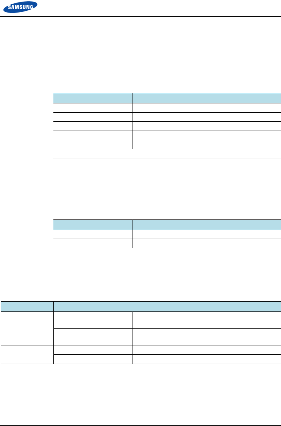
The following table lists all versions of this document.
Version Publication Date
1.0 December 2013
2.0 February 2014
3.0 February 2015
3.1 May 2015 (update power specification to -38~-56Vdc)
3.2 June 2015 (add antenna clearance distance)
Organization of This Document
Section Title Description
Chapter 1 Before Installation This chapter introduces RRH-B8 and describes
items should be understood before installation.
Chapter 2 Installation of RRH-B8 This chapter describes the procedure to install
RRH-B8.
Appendix A Acronyms This appendix describes the acronyms used in
this manual.
Appendix B Sector Antenna Installation This annex describes sector antenna
configurations and its installation requirements.
Appendix C Feeder Line Work This annex describes cautions and allowed
radius of curvature when installing feeder line.
Appendix D Assembling connector This annex describes the procedure of
assembling connector.
Appendix E Cleaning Optic Connector This annex describes the procedure of cleaning
the optic connector and cleaning tool.
Appendix F Pressure Terminal Assembly This annex describes the procedure of
assembling the pressure terminal.
Appendix G Standard Torque This annex describes the standard torque when
assembling the fixing materials.

Preface
Smart MBS RRH-B8 Installation Manual v3.0 xi
©Samsung Proprietary and Confidential
Personal and Product Safety
This product safety information includes European directives, which you must
follow. If these do not apply in your country, please follow similar directives that
do apply in your country.
Electrical
The product is designed to operate from a -48 V DC supply and is therefore
classified as Safe Extra Low Voltage (SELV) equipment.
All structural parts are grounded and all input and outputs have built-in isolation
from the network. All input and output ports that connect to external power
sources are designed to meet relevant national safety requirements.
The product contains hazardous energy levels as defined by EN 60950. Care must
be taken when maintaining this equipment as injury to personnel or damage to the
equipment could result from mistakes. Maintenance should only be carried out by
trained and competent engineers who are familiar with the relevant procedures and
instructions.
Lasers
The product is fitted with optic modules rated as Class 1 radiation-emitting devices
under EN 60825-1. During installation, operation, and maintenance, never look
into the end of an optical fiber directly or by reflection either with the naked eye or
through an optical instrument. Do not operate equipment with exposed fiber
connectors-cover these with fiber cables or blanking caps. Do not remove
equipment covers during operation unless requested to do so in the documentation.
Carry out normal safety precautions when trimming fibers during installation.
Manual Handling
Care should be taken when handling equipment. Give due consideration to the
weight of the equipment, the physical capability of the individual(s) handling the
equipment, and movements such as twisting, bending and stooping, which could
lead to skeletal and muscular injuries.
Installation
Installation must be carried out by trained and competent engineers only. All
relevant safety measures should be taken to ensure equipment is not connected to
live power and transmission sources during installation. Equipment must be
correctly installed in order to meet the relevant safety standards and approval
conditions.
Each power feed to the unit requires a separate fused feed from the provided
power supply. The cable between the power distribution point and the installed
equipment must have a minimum cross-sectional area of 2.5 mm2.

Preface
Smart MBS RRH-B8 Installation Manual v3.0 xii
©Samsung Proprietary and Confidential
Rack-mountable equipment must be placed in a standard 19-inch rack and secured
with the appropriate fixings as detailed in the installation manual.
Maintenance
Maintenance must only be carried out by a suitably trained and competent
technician. All safety instructions must be carefully observed at all times.
Equipment covers should not be removed while live power and transmission is
connected unless in a controlled environment by trained technicians.
Fire
The product is powered from a -48 V DC supply. To protect against fire, the
equipment is fused.
Environment
The product must be operated in an environment with the specified relative
humidity and ambient temperature ranges.
Keep all liquids away from the equipment as accidental spillage can cause severe
damage.
Cooling
The product cools down by its own set of cooling fans housed in a fan module.
Each fan module detects a fan that is not operating normally. LEDs on the front
panel of the fan tray provide an alarm indication in the event of fan failure.
In the event of fan failure, take urgent remedial action to restore full cooling
capacity.
Take appropriate measures to ensure that fan modules do not start spinning during
repair and maintenance procedures.
Anti-Static Precautions
The circuit boards and other modules in the product are sensitive to and easily
damaged by static electricity. If any card or sub-assembly is removed from the unit,
the following anti-static precautions must be observed at all times:
Service personnel must wear anti-static wrist straps.
Circuit boards and sub-assemblies must be placed on ground conductive mats
or in conductive bags.
All tools must be discharged to ground before use.
The anti-static wrist strap and cord must be checked at regular intervals for
their suitability for use.

Preface
Smart MBS RRH-B8 Installation Manual v3.0 xiii
©Samsung Proprietary and Confidential
Grounding
To comply with EN 60950, the equipment must be connected to a safety
grounding point via a permanent link. Grounding points are located on the product
for this purpose. Always connect the ground cable before fitting other cables. The
product must remain grounded continuously unless all connections to the power
supply and data network are all removed.
If equipment is grounded through a cabinet or rack, make sure it is done so
properly according to the installation instructions.
Power Supply Connection
The equipment is designed to be powered from a -48 V DC supply. Power
connections and installation of associated wiring must be carried out by a suitably
qualified technician.
Only devices that comply with all relevant national safety requirements should be
connected to the unit's power supply inlets. Other usage will invalidate any
approval given to this equipment.
Connection of this equipment to devices that are not marked with all relevant
national safety requirements may produce hazardous conditions on the network.
When the power supply is obtained by a rectifier/safety isolation transformer, the
supply must meet the requirements of EN 60950 providing double/reinforced
insulation between hazardous voltages and SELV/TNV circuits. Any battery must
be separated from hazardous voltages by reinforced insulation.
Indirect Connection
Before indirectly connecting any equipment to another device through a shared
power supply, ALWAYS seek advice from a competent engineer.
Devices that are not marked according to the relevant national safety standards
may produce hazardous conditions on the network.
Product Disposal
To reduce the environmental impact of products, Samsung has joined WEEE
compliance activities.
The WEEE symbol on the product indicates that the product is covered by the
European Directive 2002/96/CE for the disposal of Waste Electrical and Electronic
Equipment (WEEE). This means that the product should be disposed of separately
from the municipal waste stream via designated collection facilities appointed by
the government or the local authorities. This will help prevent potential negative
consequences for the environment and human health. Please check the terms and
conditions of the purchase contract for information about correct disposal.

Preface
Smart MBS RRH-B8 Installation Manual v3.0 xiv
©Samsung Proprietary and Confidential
Battery Disposal
The product contains a battery on the processor card. The battery should not be
disposed of with other household waste. Where marked, the chemical symbols Hg,
Cd or Pb indicate that the battery contains mercury, cadmium or lead above the
reference levels in EC Directive 2006/66. The battery incorporated in this product
is not user replaceable. For information on its replacement, please contact your
service provider. Do not attempt to remove the battery or dispose it in a fire. Do
not disassemble, crush, or puncture the battery.
End of life recycling materials information is available from Samsung.
Chemical Warning
This product contains chemicals known to the State of California to cause cancer
and reproductive toxicity.
California USA Only
This Perchlorate warning applies only to primary CR (Manganese Dioxide)
Lithium coin cells in the product sold or distributed ONLY in California USA
‘Perchlorate Material-special handling may apply, See
www.dtsc.ca.gov/hazardouswaste/perchlorate.’
Smart MBS RRH-B8 Installation Manual v3.0 1
©Samsung Proprietary and Confidential
Chapter 1 Before
Installation
System Configuration and Interface
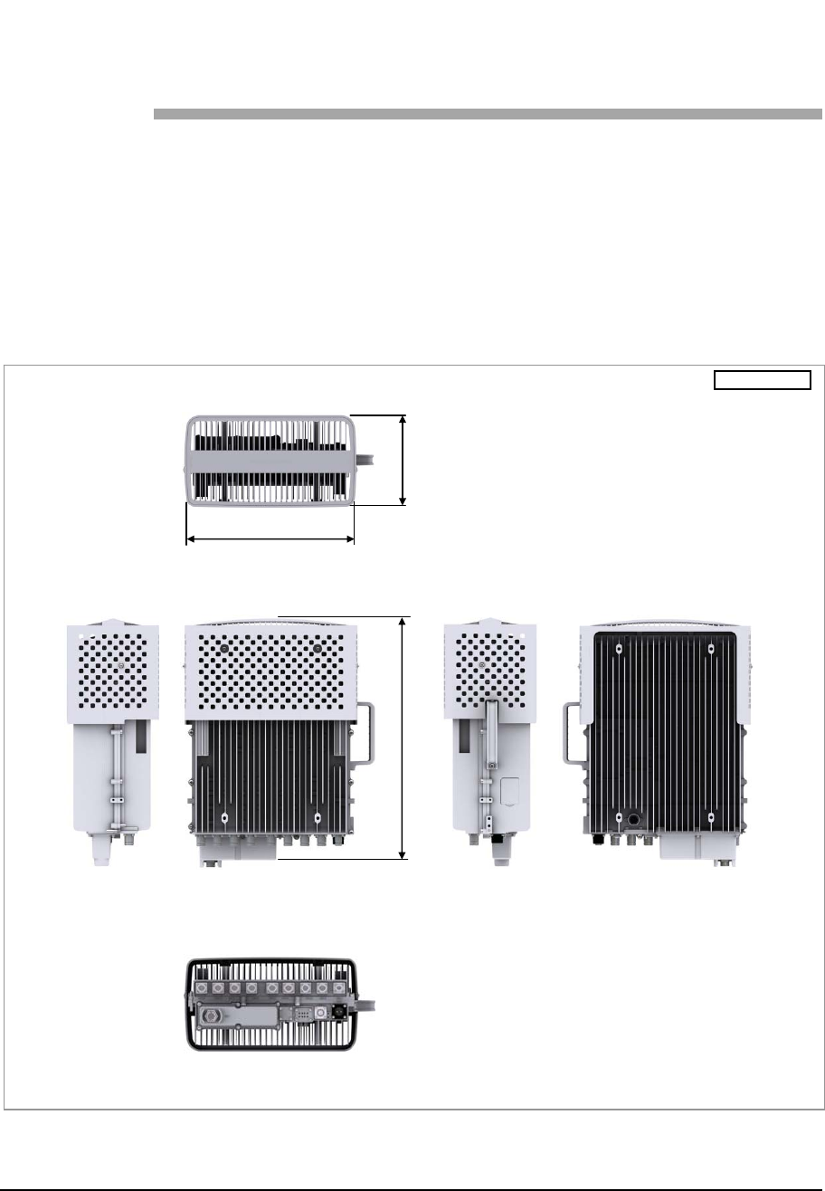
RRH-B8 Configuration
The following shows the configuration of RRH-B8.
Figure 1. RRH-B8 Configuration
[Top View]
[Front
V
iew]
[Bottom View]
[Right View] [Left View] [Rear View]
21.1 (536) 9.45 (240)
15.03 (382)
Unit:in. (mm)
Chapter 1 Before Installation
Smart MBS RRH-B8 Installation Manual v3.0 2
©Samsung Proprietary and Confidential
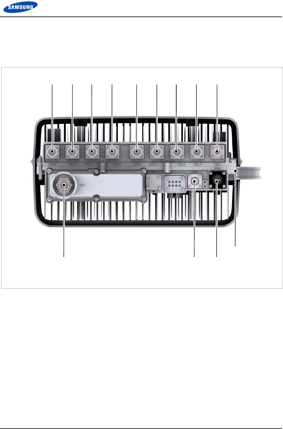
External Interfaces of RRH-B8
The following shows the external interfaces of RRH-B8.
Figure 2. External Interfaces of RRH-B8
[Bottom View]
PWR
[-48 V]
Ground
ANT_0 ANT_1 ANT_2 ANT_3 ANT_4 ANT_5 ANT_6 ANT_7 CAL
RET
CPRI (MFC)
Chapter 1 Before Installation
Smart MBS RRH-B8 Installation Manual v3.0 3
©Samsung Proprietary and Confidential
Specifications
Key Specifications
The following table shows the key specifications for RRH-B8.
Table 1. Key Specifications
Item Specifications
Air specification LTE TDD
Operating Frequency 2496~2690 MHz
RF Power per Sectora) 40 W × 4Tx (Total 160 W)
Multiple Antenna 8T8R/4T8R/4T4R/2T2R
DU~RRH-B8 Interface 10 Gbps, CPRI 4.0 (Optic)
a) Output power at the RU antenna port. (Not external filter antenna port)
Power Specifications
The following table shows the power specifications for RRH-B8. RRH-B8
complies with UL60950 safety standard for electrical equipment.
Table 2. Power Specifications
Item Specifications
Input voltage -48 V DC: -38~-56 V DC
Current consumption (Max.) 17 A
Unit Size and Weight
The following table shows the size and weight of RRH-B8.
Table 3. Unit Size and Weight
Item Specifications
Size (W × D × H) 13.78 × 6.75 × 17.72 (in.)
350 × 171.5 × 450 (mm)
Without. Finger guard, MFC Box
15.03 × 8.03 × 21.26 (in.)
382 × 204 × 540 (mm)
With. Finger guard, MFC Box
Weight 56.00 lb (25.4 kg) Without. Finger guard, MFC Box
59.74 lb (27.1 kg) With. Finger guard, MFC Box

Chapter 1 Before Installation
Smart MBS RRH-B8 Installation Manual v3.0 4
©Samsung Proprietary and Confidential
Ambient Conditions
This section describes the operating temperature, humidity level and other ambient
conditions and related standard of RRH-B8.
The following table shows the ambient conditions and related standard of RRH-B8.
Table 4. Ambient Conditions
Item Range
Temperaturea) -40~131°F (-40~55°C) without solar load
Humiditya) 10~95 %
The moisture content must not exceed 0.024 kg per 1 kg
of air.
Altitude 0~6000 ft (0~1800 m)
Vibration GR-63-CORE Sec.4.4
Earthquake
Office Vibration
Transportation Vibration
Noise (sound pressure level) Max. 65 dBA at distance of 5 ft (1.5 m) and height of 3 ft
(1.0 m)
Electromagnetic Interference
(EMI)
FCC Title47 Part 15 Class B
US Federal Regulation FCC Title47 Part27
a) Temperature and humidity are measured at 59 in. (1.5 m) above the floor and at 15.8
in. (400 mm) away from the front panel of the RRH-B8.

Smart M
B
©Samsu
n
Inst
Befo
r
OSH
A
B
S RRH-B8 I
n
n
g Proprietar
y
allati
o
T
i
n
r
e Instal
l
A
Trainin
I
t
S
G
a
a
R
n
stallation Ma
y
and Confide
n
o
n Pre
T
he followin
g
n
stallation.
l
ation
Install a
h
located.
Install a
r
Cover ex
p
or fence
o
Study us
e
use it.
Check th
e
g
t
is importa
n
S
UPERVISI
N
G
.C. employ
e
a
nd maintain
i
a
nd abide by
R
eview syst
e
OSHA st
agency o
f
OSHA’s
OSHA
w
n
ual v3.0
n
tial
cauti
o
g
precaution
h
igh voltage
r
estricted en
t
p
osed areas
o
ff the area.
e
of the fire
a
e
location o
f
n
t that ALL
W
N
G THIS S
T
e
rs as havin
g
i
ng MMBS
a
all require
m
ms checklis
t
ands for the
f
the U.S. D
e
responsibili
t
w
ebsite: http:
/
o
n
n
must be ob
s
warning sig
n
t
ry warning
s
such as junc
a
larm and th
e
f
the nearest
W
ORKERS
A
T
A installati
o
g
sufficient t
r
a
nd battery
s
m
ents as defi
n
t
.
Occupation
a
e
partment o
f
t
y is worker
/
/www.osha.
s
erved to pr
e
n
near the a
r
s
ign near th
e
tions, ceilin
g
e
location o
f
emergency
e
A
ND LEA
D
o
n manual is
r
aining and
a
s
ystems, and
n
ed in this m
a
l Safety an
d
f
Labo
r
safety and h
e
gov
Chapt
e
vent accide
n
ea where hi
g
potential ac
g
s, footholds
f
the fire exti
n
e
xit.
D
S PERFOR
M
validated a
s
a
dequate pro
that they ar
e
a
nual and th
e
d
Health Ad
m
e
alth protect
i
e
r 1 Before In
n
ts during R
R
g
h voltage c
a
c
cident area.
s
etc. with sa
i
nguisher an
d
M
ING AN
D
s
qualified b
y
o
ficiency in i
n
e
aware, und
e
h
e Field Site
A
m
inistration,
t
ion
s
tallation
5
R
H-B8
a
ble is
f
ety rails
d
how to
D
y
their
n
stalling
e
rstand,
A
udit
an
Chapter 1 Before Installation
Smart MBS RRH-B8 Installation Manual v3.0 6
©Samsung Proprietary and Confidential
During Installation
Cut all equipment power before installation.
Always wear protection gloves and goggles when drilling holes into the wall
or ceiling.
To prevent electric shocks from metallic objects, remove all accessories such
as watches or rings.
Wearing protection gloves and goggles
Make sure to wear protection gloves and goggles to prevent damages from debris
while drilling holes in a wall or ceiling.
Watches, Rings, and Other Metallic Accessories
Do not wear accessories such as watches and rings in order to prevent electrical
shock.
Do not work by yourself
Do not work by yourself in any key process.
Do not use base station antenna within the distance of 1600 cm from people and
also do not co-locate nor operate in conjunction with any other antenna or
transmitter for the protection of general public from exposure to radio frequency
electromagnetic field.
Cable Path Inspection
When installing a cable that connects between the rectifier, Main Ground Bar
(MGB), and backhaul device, etc. within the system, the cable path length and the
cable installation method, etc. must be inspected.
Follow these guidelines when inspecting the cabling path.
A minimum cable length must be selected provided that it does not affect the
cable installation and maintenance.
The cable must be placed in a location where it will not be damaged by
external factors. (Power line, flooding, footpaths, etc.)
In areas where the cable can be damaged by external factors, ensure that
measures are taken to prevent damages to the cable. (Cable tray, ducts, flexible
pipe, etc.)

Chapter 1 Before Installation
Smart MBS RRH-B8 Installation Manual v3.0 7
©Samsung Proprietary and Confidential
Cable Cutting
Measure the exact distance, carefully checking the route, and cut the cable using a
cutting tool.
Follow these guidelines when cutting the cable.
Cut the cable to the length determined in the Cable Path Inspection step.
Use a dedicated cable cutting tool.
Cut the cable at right angles.
Be careful to keep the cable away from any moisture, iron, lead, dust or other
foreign material when cutting. Remove any foreign material attached to the
cable using solvent and a brush.
Cable Installation
Cable installation involves running the cable along the cabling path to the target
connector of the system or an auxiliary device after cable path inspection and cable
cutting have been completed.
Follow these guidelines when installing a cable.
Be careful not to damage the cable.
If the cable is damaged, cut out the damaged section before installing.
Run the cable so that it is not tangled. In particular, when installing a cable
from a horizontal section to a vertical section, be careful not to reverse the
upper and lower lines of the cable.
Always use the maximum curvature radius possible, and make sure that the
minimum curvature radius specification is complied with.
If the cable needs to be protected, use a PVC channel, spiral sleeve, flexible
pipe, and cable rack, etc.
Table 5. Minimum Allowed Cable Bend Radius
No Type Min. Allowed Cable Bend Radius Remarks
1 GV/CV/FR-8 8 times of the cable external diameter 0.6/1 KV cable
2 Optic Cable 20 times of the cable external diameter -
3 UTP/FTP/S-FTP Cable 4 times of the cable external diameter PVC/LSZH, 4 Pair
4 1/2 in. Feeder Line (Indoor) 1.26 in. (32 mm) RFS, LS
5 1/2 in. Feeder Line (Outdoor) 4.92 in. (125 mm) RFS, LS
6 7/8 in. Feeder Line (Outdoor) 9.84 in. (250 mm) RFS, LS
7 1 1/4 in. Feeder Line (Outdoor) 14.96 in. (380 mm) RFS, LS
8 1 5/8 in. Feeder Line (Outdoor) 19.69 in. (500 mm) RFS, LS
9 LMR-400 1 in. (25.4 mm) Installation
4 in. (101.6 mm) Repeated
10 RG-316D 0.59 in. (15 mm) -

Chapter 1 Before Installation
Smart MBS RRH-B8 Installation Manual v3.0 8
©Samsung Proprietary and Confidential
No Type Min. Allowed Cable Bend Radius Remarks
11 Hybrid
Cable
External diameter: 0.98
in. (25 mm)
11.81 in. (300 mm) -
External diameter: 1.06
in. (27 mm)
13.0 in. (330 mm) -
External diameter: 1.18
in. (30 mm)
15.35 in. (390 mm) -
External diameter: 1.26
in. (32 mm)
17.71 in. (450 mm) -
* If the allowed cable bend radius is specified by the manufacturer, comply with the bend radius specified.
Cable Binding
Cable binding involves fixing and arranging an installed cable using binding
strings, cable ties, binding lines, and ram clamps, etc.
Follow these guidelines when binding a cable.
Be careful not to damage the cable during binding.
Use appropriate cable binding tools according to the target location (indoor or
outdoor, etc.) and the use of the cable (power cable, optical cable, RF cable,
etc.).
Do not let the cutting section of a cable tie and binding line, etc. be exposed to
the outside. This may cause damage to cables or personal injury. Make sure
that the cutting sections of cables are not exposed to the outside.
Trim the binding string so that you have about 1.97 in. (5 cm) of string left
from the knot. And insert the remaining string into the knot and make sure the
knot does not loosen.
If there is a potential danger of contact failure in a connector connection due to
tension, install the cable in the shortest distance.
Connector Attachment
Connector attachment involves assembling a connector to an installed cable or to a
device on the site.
Follow these guidelines when attaching a connector.
Make sure you are fully aware of the connector assembly method before
assembling a connector. Assemble the connector in accordance with its pin
map.
Each connector has a hook to prevent its core positions from being changed.
Use a heat shrink tube at a connector connection for cables that are installed
outdoor, such as RF cables, to prevent water leakage and corrosion from
occurring at the part exposed to the outside.
Connect each cable of the connector assembly in a straight line.
Chapter 1 Before Installation
Smart MBS RRH-B8 Installation Manual v3.0 9
©Samsung Proprietary and Confidential
Be careful when connecting a cable not to trigger contact failure at a connector
connection due to tension.
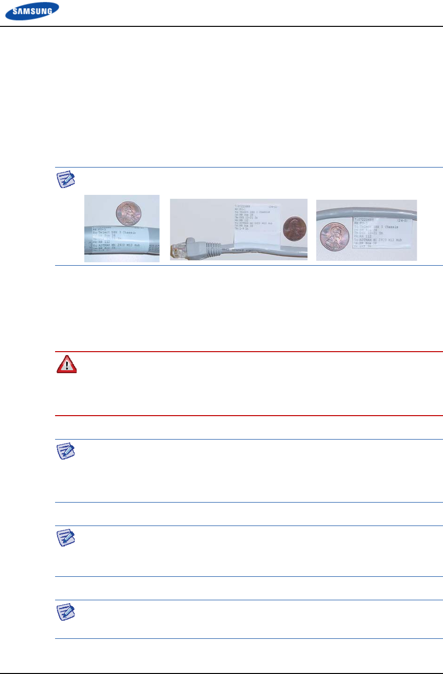
Identification Tag Attachment
Identification tag attachment involves attaching a marker cable tie, nameplate, and
label, etc. to the both ends of a cable (connections to a connector) to identify its
use and cabling path.
Follow the Cable labeling standards as below;
Category: Full Wrap, Full Flag, Half Flag, etc.
Follow these guidelines when attaching an identification tag.
When installing a cable outdoor, use relief engraving and coated labels, etc. to
prevent markings from being erased.
Since the form and attachment method for identification tags are different for
each provider, consult with the provider before attaching them.
When connecting the cables, always connect the ground cable first. If worker
contacts the equipment, connect a cable or perform maintenance without
connecting the ground cable, the system can be damaged or a worker may be
injured due to static electricity and short circuit.
When cutting the cable after installation, make sure that the connector is
disconnected. Installation of the cable with the connector connected to the system
may cause contact failure or damage to the connector assembled to the system and
the cable due to cable tension or the electrician’s mistakes
When installing, take care not to overlap or tangle the cables; also, consider future
expansion. Install the DC power cable and data transmission cable away from the
AC power cable to prevent electromagnetic induction.
The cable works require knowledge for the cabling works such as cable
installation/binding.

Chapter 1 Before Installation
Smart MBS RRH-B8 Installation Manual v3.0 10
©Samsung Proprietary and Confidential
After Installation
Cover the cable hole on the floor with a solid cover.
Remove all installation residues; clean the area.
The optical module and cable used in the system emit bright laser beams.
Always handle them with care as there is risk of serious injury if the eyes are
exposed to the laser beam of the optical cable.
While cleaning the power supply device, take caution that the device does not
come in contact with alien bodies that may cause power failure.
Smart M
B
©Samsu
n
Inst
Table 6.
No.
1
2
3
4
5
6
7
8
9
10
11
13
B
S RRH-B8 I
n
n
g Proprietar
y
allati
o
T
r
e
s
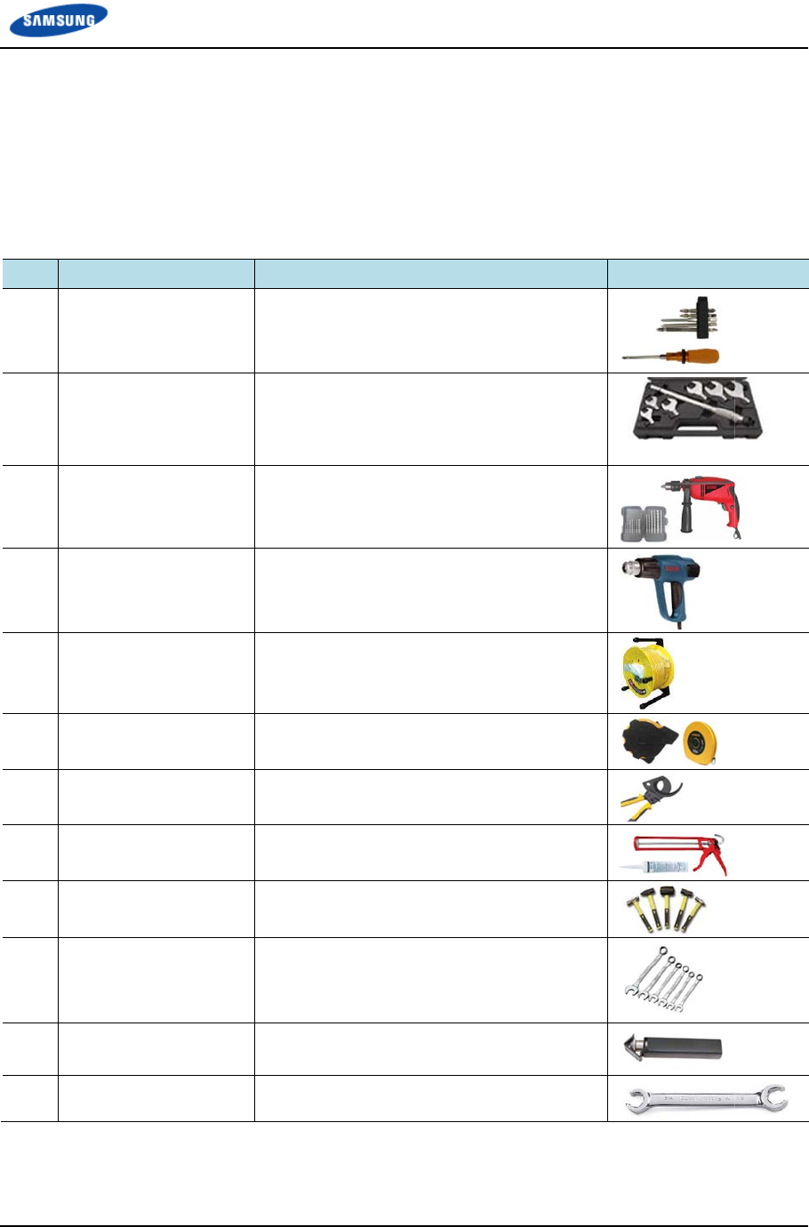
Basic Install
a
Name
Torque Drive
r
Torque Wren
Drill/Bit Set
Heating Gun
Power Exten
s
Tape Measu
r
Cable Cutter
Silicon Gun/
S
Hummer Set
Spanner
Wire Stripper
Flare Nut Wr
e
n
stallation Ma
y
and Confide
n
o
n To
o
T
he basic to
o
e
quired for
e
tarting insta
l
a
tion Tools
r
Set
ch Set
s
ion Cable
r
e
S
ilicon
e
nch
n
ual v3.0
n
tial
o
l
o
ls for install
e
ach installa
t
l
lation.
Purpose
No.0~+ No.
3
lbf·ft (1.0~6
0
M6~M14
0.72~2.17 lb
f
7.23~36.15 l
Replaceable
0.24~0.67 in
122~572°F (
98.42 ft (30
m
16.4 ft/164 f
t
12.8 in. (325
Normal/Gra
y
Still/Rubber/
P
0.39 in., 0.5
1
1.42 in.
(10 mm, 13
m
mm)
0.24~0.94 in
Hexagon 7/
8
l
ation are lis
t
t
ion procedu
r
3
(M2.6~M6 ‘
+
0
kgf·cm)
f·ft (10~30 kg
f
bf·ft (100~50
0
e
head
. (6~17 mm)
50~300°C)
m
)
t
(5 m/50 m)
5
mm)
y
& Colorless
PVC
1
in., 0.67 in.,
m
m, 17 mm,
1
. ( 6~24 mm)
8
in.
t
ed in the ta
b
r
e need to b
e
+
’ Driver) 0.07
~
f
·cm),
0
kgf·cm),
0.75 in., 0.94
1
9 mm, 24 m
m
Chapt
e
b
le below. T
h
e
identified
a
Sp
e
~
4.34
in.,
m
, 36
e
r 1 Before In
h
e additiona
l
a
nd prepared
e
cification
s
tallation
11
l
tools
before

Chapter 1 Before Installation
Smart MBS RRH-B8 Installation Manual v3.0 12
©Samsung Proprietary and Confidential
The required installation tools may vary depending on the conditions at the site.
In addition to the basic tools, a protractor, compass, GPS receiver, ladder, safety
equipment, cleaning tools etc. should also be prepared in consideration of the site
conditions.
Smart MBS RRH-B8 Installation Manual v3.0 13
©Samsung Proprietary and Confidential
Chapter 2 Installation of
RRH-B8
Installation Procedure
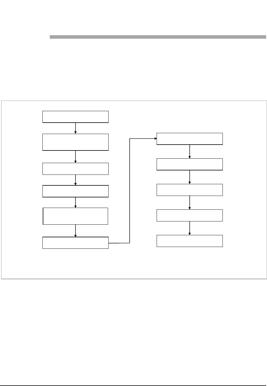
The following diagram shows RRH-B8 installation procedure.
Figure 3. System Installation & Cable Connection Procedure
Cabling in the Cabinet
Cabling the Hybrid Cable
Check
* This procedure may be omitted when using an existing installation. If required, additional work can be
done through the standard procedure, and thus will not be described in this manual.
Antenna Installation
Material Check
* Antenna Mounting
System Installation
Cabling from Antenna
to RRH
RRH Installation
* Bus bar Installation
RRH Grounding
Cabling in the RRH
Chapter 2 Installation of RRH-B8
Smart MBS RRH-B8 Installation Manual v3.0 14
©Samsung Proprietary and Confidential
Foundation Work
Equipment Arrangement
A minimum distance must be secured around the RRH-B8 in each direction for
installation and maintenance.
Table 7. Recommended Distances for System Arrangement
Item Recommended Distances
Front/Rear 31.5 in. (800 mm) or more
Sides 23.62 in. (600 mm) or more
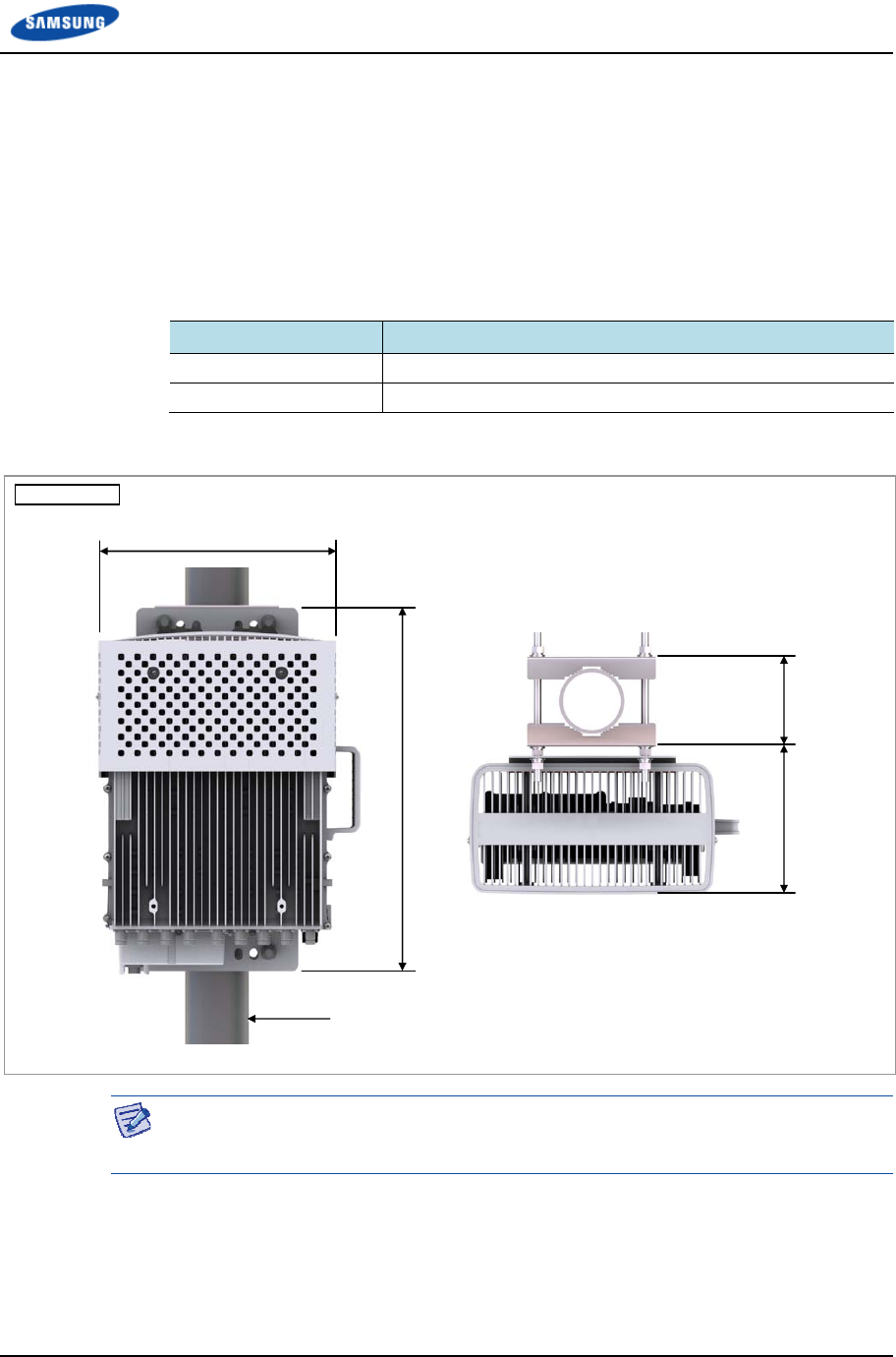
Figure 4. RRH-B8 Installation Space (1 Sector Pole Type)
The figure above illustrates the installation space using a 4 in. (101.6 mm)/90 A
diameter pole. The measures may differ depending on the diameter of the pole.
22.98 (583.6)
Pole
(Φ 3~4.5 in./Φ 76.3~114.3 mm)
5.57 (141.6)
15.03
(
382
)
Unit: in. (mm)
9.09 (231)
Chapter 2 Installation of RRH-B8
Smart MBS RRH-B8 Installation Manual v3.0 15
©Samsung Proprietary and Confidential
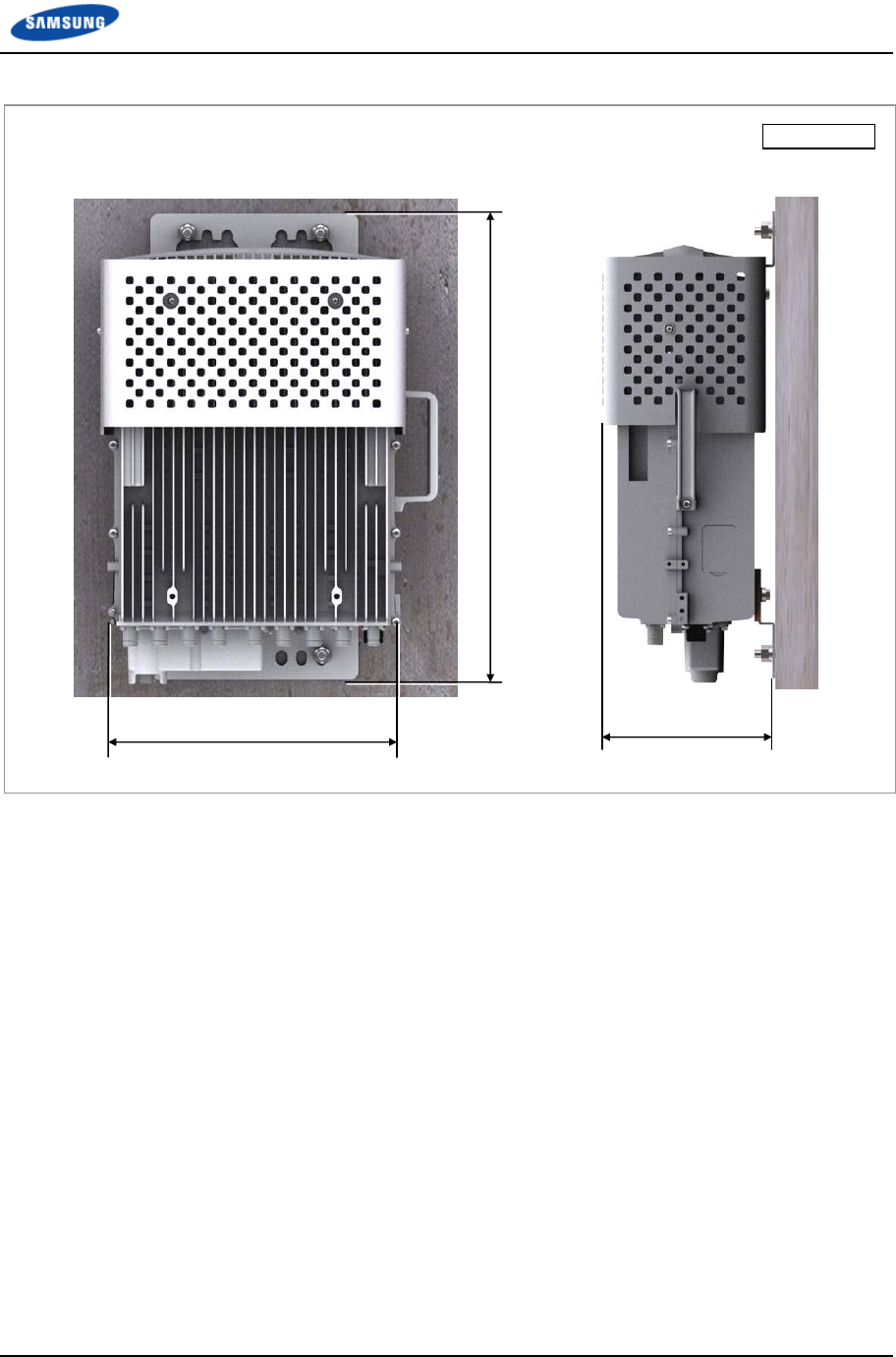
Figure 5. RRH-B8 Installation Space (Wall Type)
Unit: in. (mm)
8.54 (217)
22.98 (583.6)
15.03 (382)

Chapter 2 Installation of RRH-B8
Smart MBS RRH-B8 Installation Manual v3.0 16
©Samsung Proprietary and Confidential
Unpacking and Transporting
This paragraph describes the work to unpack cabinets and other components and
transport them to the place to be installed. The cabinet is externally packed and
cabinet and other components are individually packed.
The external packing should be unpacked outside of the building. If necessary,
it can be unpacked after transporting to the area near installation place.
Transport the cabinet to the installation place. Be aware of the damage of walls,
pillars, and bottom of the passage when transporting the cabinet.
Transport other components with packing and sort by types.
Bringing in Items
Bring in items, taking care of the followings:
Regarding equipment weight and size, check the path to bring the equipment.
Lay Iron and veneer boards on stairs or doorsills to make the transportation
easy.
When bring in equipment, beware of damage or impairment of main entrance,
walls, pillars, and floors of the station. Prepare protection materials and fix
them with a high-strength adhesive.
Carry boards in packing status, and unpack them when installing or mounting.
Vibration Level for Transportation
When carrying the system, fasten the system firmly not to exceed the proper
vibration level from 1 to 500 Hz.
When carrying system, use a lift to prevent accidents. However, if the system
should be carried by people, enough people are required to carry the system.
Before moving the system, check the storage place for the system and remove
obstacles in advance.
While moving system, boards and other devices should not be shocked
physically and damaged caused by dust, moisture, and static electricity.
System should be installed in a location whose access is not easy from outside.

Chapter 2 Installation of RRH-B8
Smart MBS RRH-B8 Installation Manual v3.0 17
©Samsung Proprietary and Confidential
Unpacking Items
The procedure to unpack items is as follows:
The packing items should be packed until they reach the installation place.
The items are classified in accordance with each job specification and stored
on a place with no interference on working.
Unpacked systems should be installed immediately. If not installed
immediately, the systems should be stored in the installation place temporarily.
Unpack the inner packaging after each system is placed on its installation
location.
Unpack the inner packaging after each system is placed on its installation
location.
Do not recycle the packaging waste. Dispose of them pursuant to the rules.
Chapter 2 Installation of RRH-B8
Smart MBS RRH-B8 Installation Manual v3.0 18
©Samsung Proprietary and Confidential
Fixing the System
Preparations
For the system fixation, assemble the unit mounting brackets and finger guard first
on the ground.
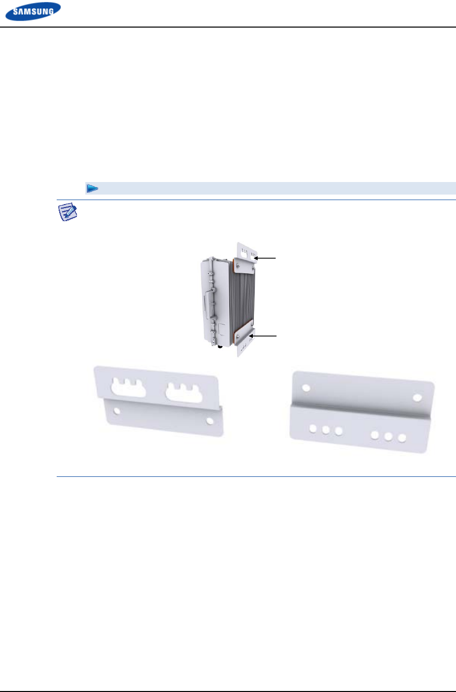
Fixing Unit Mounting Bracket
Fixing Unit Mounting Bracket
There are two types of unit mounting brackets, for top and bottom.
[Unit Mounting Bracket_Top] [Unit Mounting Bracket_Bottom]
Unit Mounting Bracket_Top
Unit Mounting Bracket_Bottom
Chapter 2 Installation of RRH-B8
Smart MBS RRH-B8 Installation Manual v3.0 19
©Samsung Proprietary and Confidential
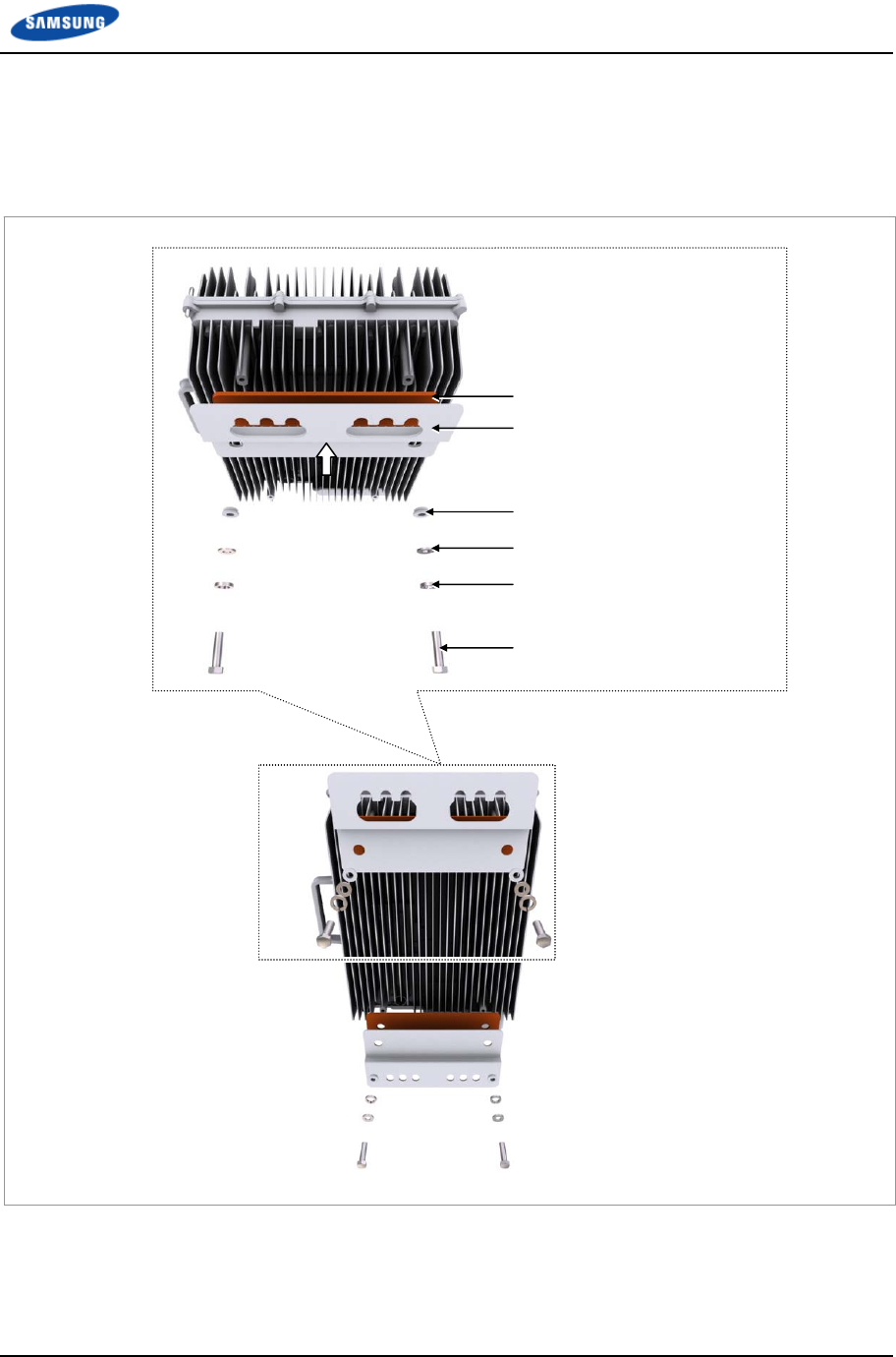
1 Allign the bakelite and unit mounting bracket_top to the upper rear fixing
holes of RRH-B8 and fix them firmly in place using insulation bushings, plain
washers, spring washers, and M8 hex. bolts.
Figure 6. Fixing Unit Mounting Bracket (1)
Bakelite
Unit Mounting Bracket_Top
M8 Insulation Bushing
M8 Plain Washer
M8 Spring Washer
M8 × 30L Hex. Bolt
Chapter 2 Installation of RRH-B8
Smart MBS RRH-B8 Installation Manual v3.0 20
©Samsung Proprietary and Confidential
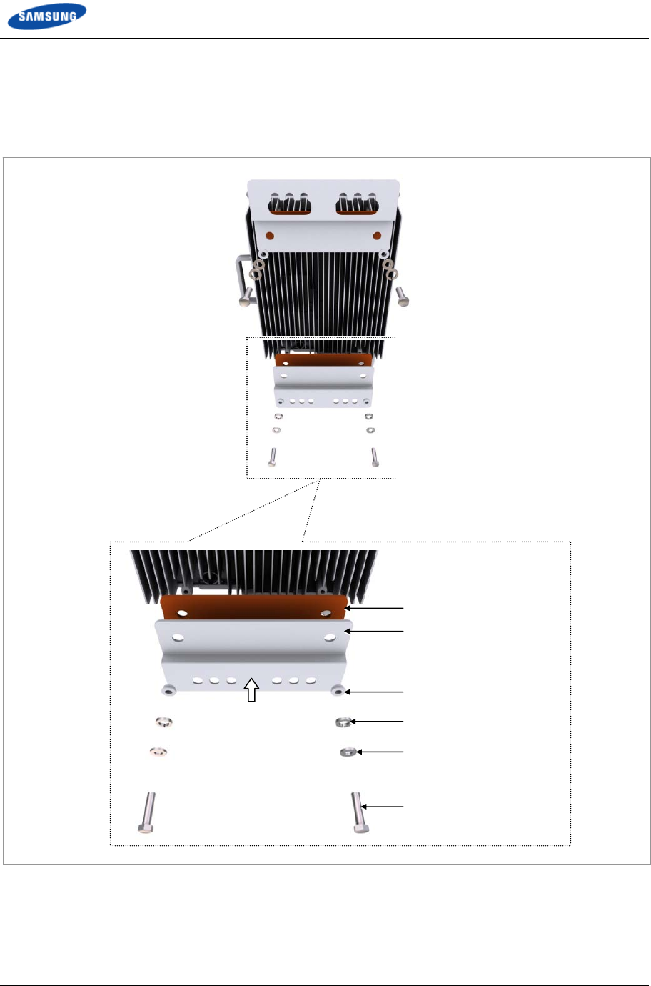
2 Allign the bakelite and unit mounting bracket_bottom to the lower rear fixing
holes of RRH-B8 and fix them firmly in place using insulation bushings, plain
washers, spring washers, and M8 hex. bolts.
Figure 7. Fixing Unit Mounting Bracket (2)
Bakelite
Unit Mounting Bracket_Top
M8 Insulation Bushing
M8 Plain Washer
M8 Spring Washer
M8 × 30L Hex. Bolt

Chapter 2 Installation of RRH-B8
Smart MBS RRH-B8 Installation Manual v3.0 21
©Samsung Proprietary and Confidential
Fixing Finger Guard
Fixing Finger Guard
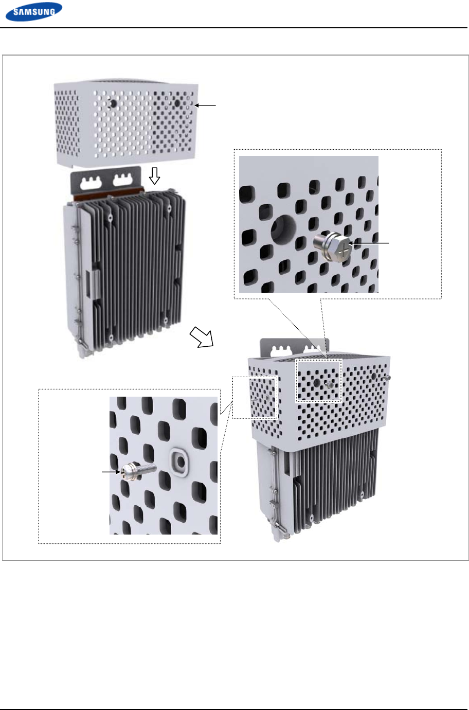
1 Place the finger guard to the fixing holes at the RRH-B8.
2 Fix the finger guard to the RRH-B8 using the screws on the front, left, and
right sides of RRH-B8.
o Front side: M8 x 15L Hex. Screw (WSP)
o Left/Right sides: M5 × 12L SEMS
Chapter 2 Installation of RRH-B8
Smart MBS RRH-B8 Installation Manual v3.0 22
©Samsung Proprietary and Confidential
Figure 8. Fixing Finger Guard
Finger Guard
M5 × 12L SEMS
M8 × 15L
Hex. Screw
(WSP)
Chapter 2 Installation of RRH-B8
Smart MBS RRH-B8 Installation Manual v3.0 23
©Samsung Proprietary and Confidential
Fixing Wall Mount
Fixing Wall Mount
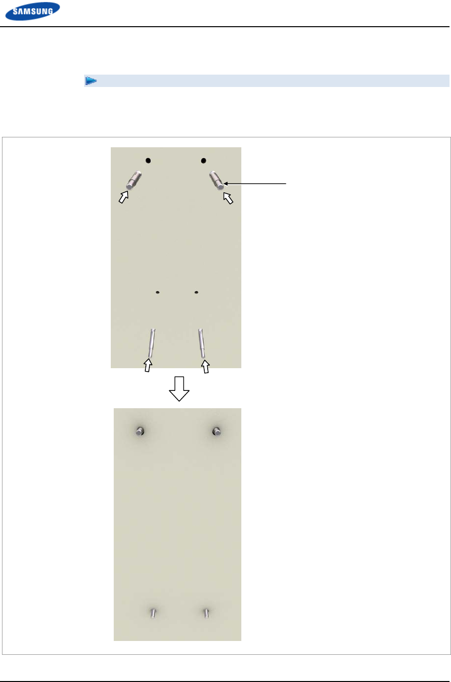
1 Fix M12 anchor bolts to the drilled holes on the wall.
Figure 9. Fixing Wall Mount (1)
M12 Anchor Bolt
Chapter 2 Installation of RRH-B8
Smart MBS RRH-B8 Installation Manual v3.0 24
©Samsung Proprietary and Confidential
2 Hang the RRH-B8 unit mounting brackets by alligning the bracket holes to the
M12 anchor bolts that are fixed on the wall and fix them using M12 plain
washers, spring washers, and hex. bolts.
Figure 10. Fixing Wall Mount (2)
M12 Plain Washer
M12 Spring Washer
M12 Hex. Nut
M12 Anchor Bolt
M12 Plain Washer
M12 Spring Washer
M12 Hex. Nut

Chapter 2 Installation of RRH-B8
Smart MBS RRH-B8 Installation Manual v3.0 25
©Samsung Proprietary and Confidential
The fasteners used to attach the wall mount, including the anchor bolts, spring
washers, plain washers and hex. nuts must be made of stainless steel (STS 304).
Otherwise, it may cause corrosion and rust to fixing materials.
Chapter 2 Installation of RRH-B8
Smart MBS RRH-B8 Installation Manual v3.0 26
©Samsung Proprietary and Confidential
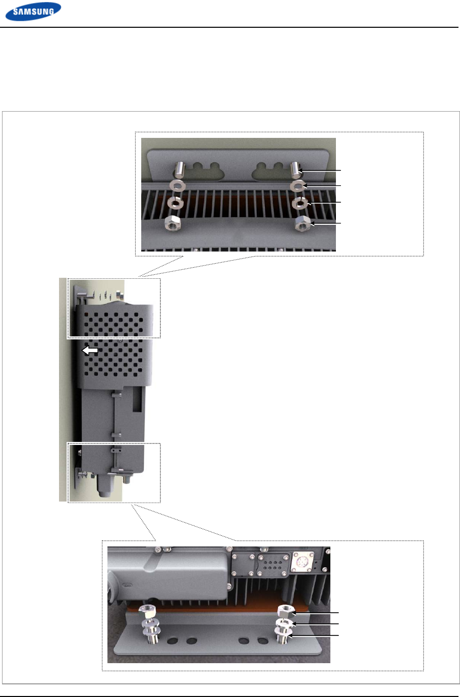
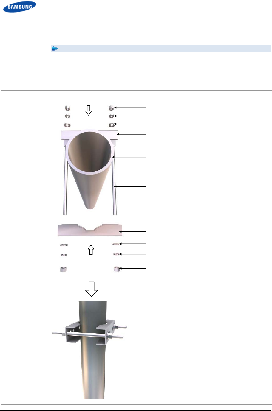
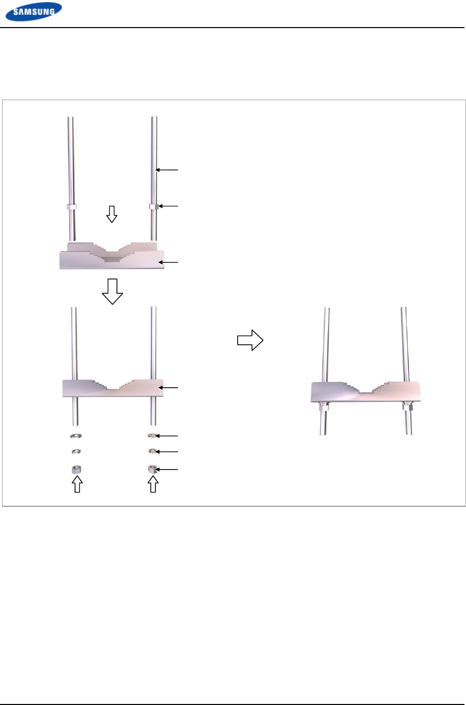
1 Sector Pole Fixation
1 Sector Pole Fixation
1 Attach the pole mounting brackert-1, 2 to match the installation location of
RRH-B8.
Figure 11. 1 Sector Pole Fixation (1)
Pole Mounting Bracket-1
M12 Plain Washer
M12 Spring Washer
M12 Hex. Nut
M12 Stud Bolt
Pole Mounting Bracket-2
M12 Plain Washer
M12 Spring Washer
M12 Hex. Nut
Pole
(Φ 3~4.5 in./Φ 76.3~114.3 mm)
Chapter 2 Installation of RRH-B8
Smart MBS RRH-B8 Installation Manual v3.0 27
©Samsung Proprietary and Confidential
2 Temporarily attach the plain washer, spring washer, Hex. Nut to the stud bolt
where the RRH-B8 is to be attached.
Figure 12. 1 Sector Pole Fixation (2)
Pole Mounting Bracket-1
M12 Hex. Nut
M12 Plain Washer
M12 Spring Washer
M12 Hex. Nut
M12 Stud Bolt
0.4 in. (10 mm)
Pole Mounting Bracket-2
Chapter 2 Installation of RRH-B8
Smart MBS RRH-B8 Installation Manual v3.0 28
©Samsung Proprietary and Confidential
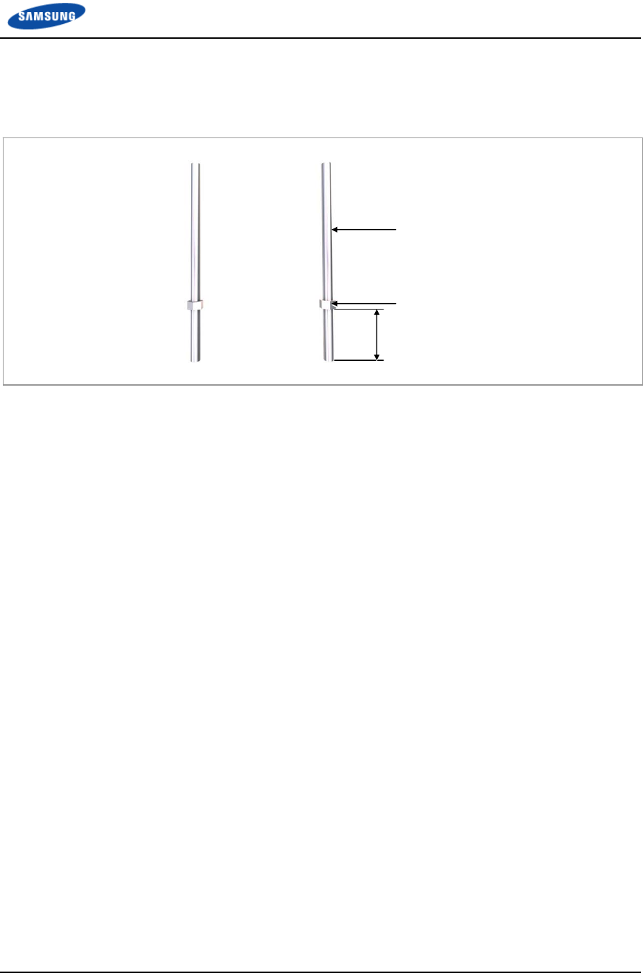
3 Attach the M12 Hex. Nut to the point 1.96 in. (50 mm) from one end of the
M12 stud bolt.
Figure 13. 1 Sector Pole Fixation (3)
M12 Stud Bolt
1.96 in.
(50 mm)
M12 Hex. Nut
Chapter 2 Installation of RRH-B8
Smart MBS RRH-B8 Installation Manual v3.0 29
©Samsung Proprietary and Confidential
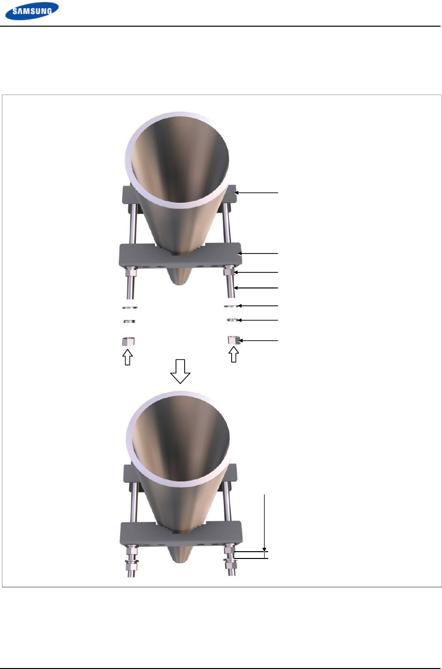
4 Insert the M12 stud bolt into the hole of the Pole mounting bracket-3 and use
plain washer, spring washer, Hex. Nut to fasten it hard.
Figure 14. 1 Sector Pole Fixation (4)
M12 Hex. Nut
M12 Stud Bolt
Pole Mounting Bracket-3
Pole Mounting Bracket-3
M12 Hex. Nut
M12 Spring Washer
M12 Plain Washer
Pole Mounting Bracket Assembly
Chapter 2 Installation of RRH-B8
Smart MBS RRH-B8 Installation Manual v3.0 30
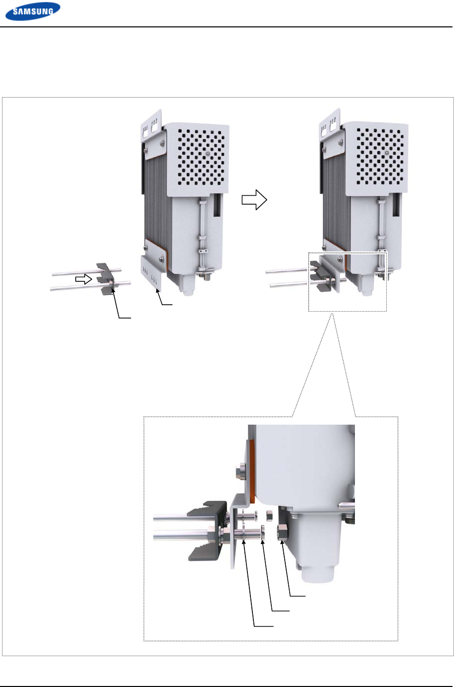
©Samsung Proprietary and Confidential
5 Attach the pole mounting bracket assembly to the RRH-B8 unit mounting
bracket-bottom.
Figure 15. 1 Sector Pole Fixation (5)
M12 Hex. Nut
Pole Mounting Bracket assembly
Unit Mounting Bracket-Bottom
M12 Spring Washer
M12 Plain Washer
Chapter 2 Installation of RRH-B8
Smart MBS RRH-B8 Installation Manual v3.0 31
©Samsung Proprietary and Confidential
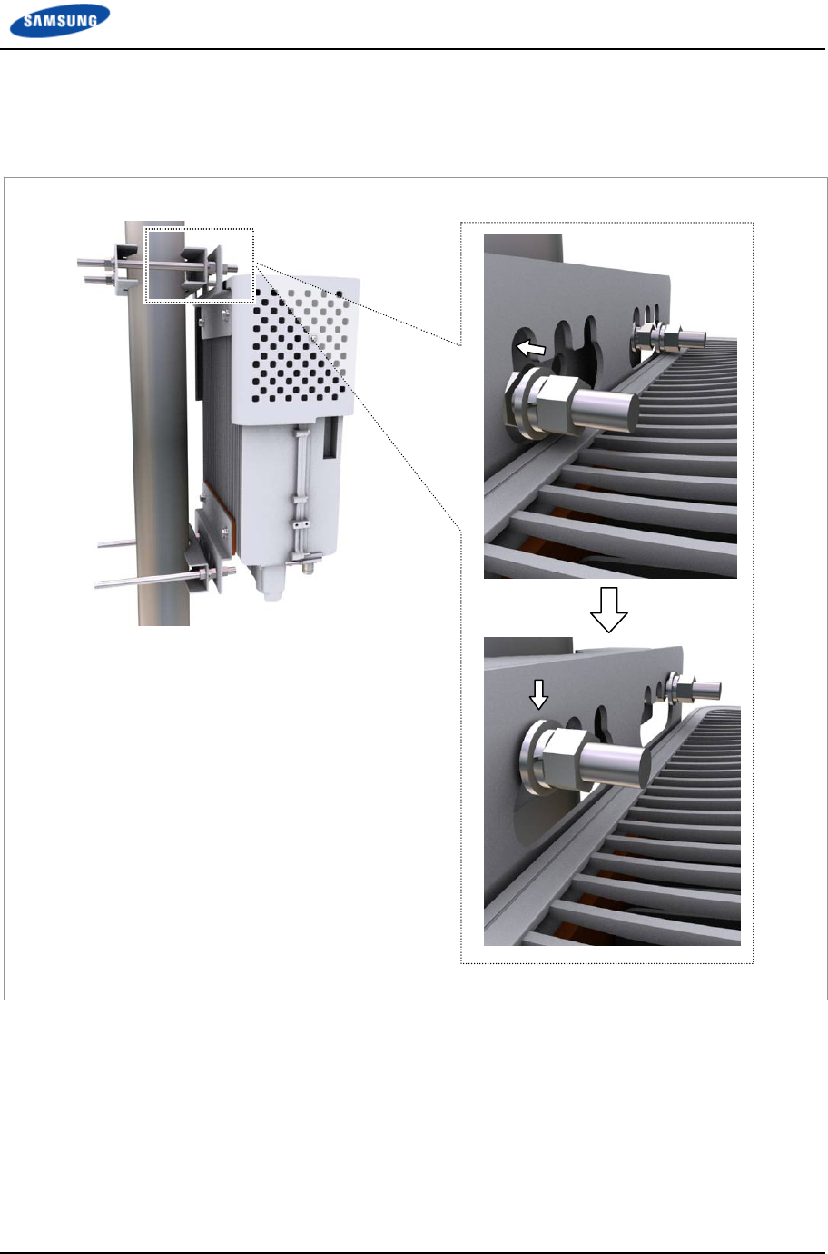
6 Hang the RRH-B8 to the stud bolts fixed on the pole using the fixing holes of
the RRH-B8 unit mounting bracket-top.
Figure 16. 1 Sector Pole Fixation (6)
Chapter 2 Installation of RRH-B8
Smart MBS RRH-B8 Installation Manual v3.0 32
©Samsung Proprietary and Confidential
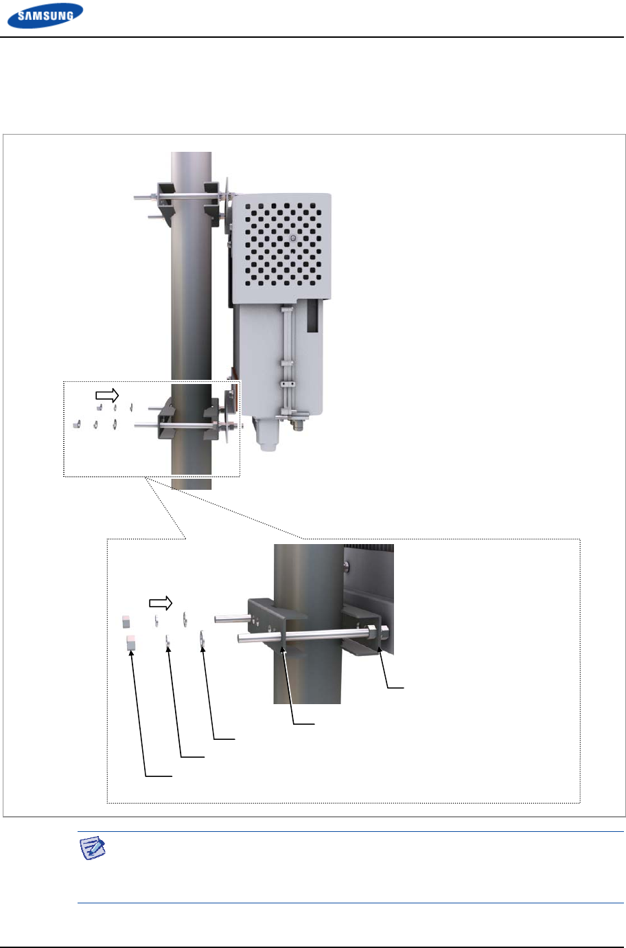
7 Attach the pole mounting bracket assembly on the lower part of RRH-B8 and
the pole mounting bracket-4.
Figure 17. 1 Sector Pole Fixation (7)
The fasteners used to attach the pole, including the hex. bolts, hex. nut, spring
washers and plain washers must be made of stainless steel (STS 304). Otherwise, it
may cause corrosion and rust to fixing materials.
Pole Mounting Bracket-4
M12 Plain Washer
M12 Spring Washer
M12 Hex. Nut
Pole Mounting Bracket Assembly
Chapter 2 Installation of RRH-B8
Smart MBS RRH-B8 Installation Manual v3.0 33
©Samsung Proprietary and Confidential
Cabling
The following shows the cables connected to RRH-B8.
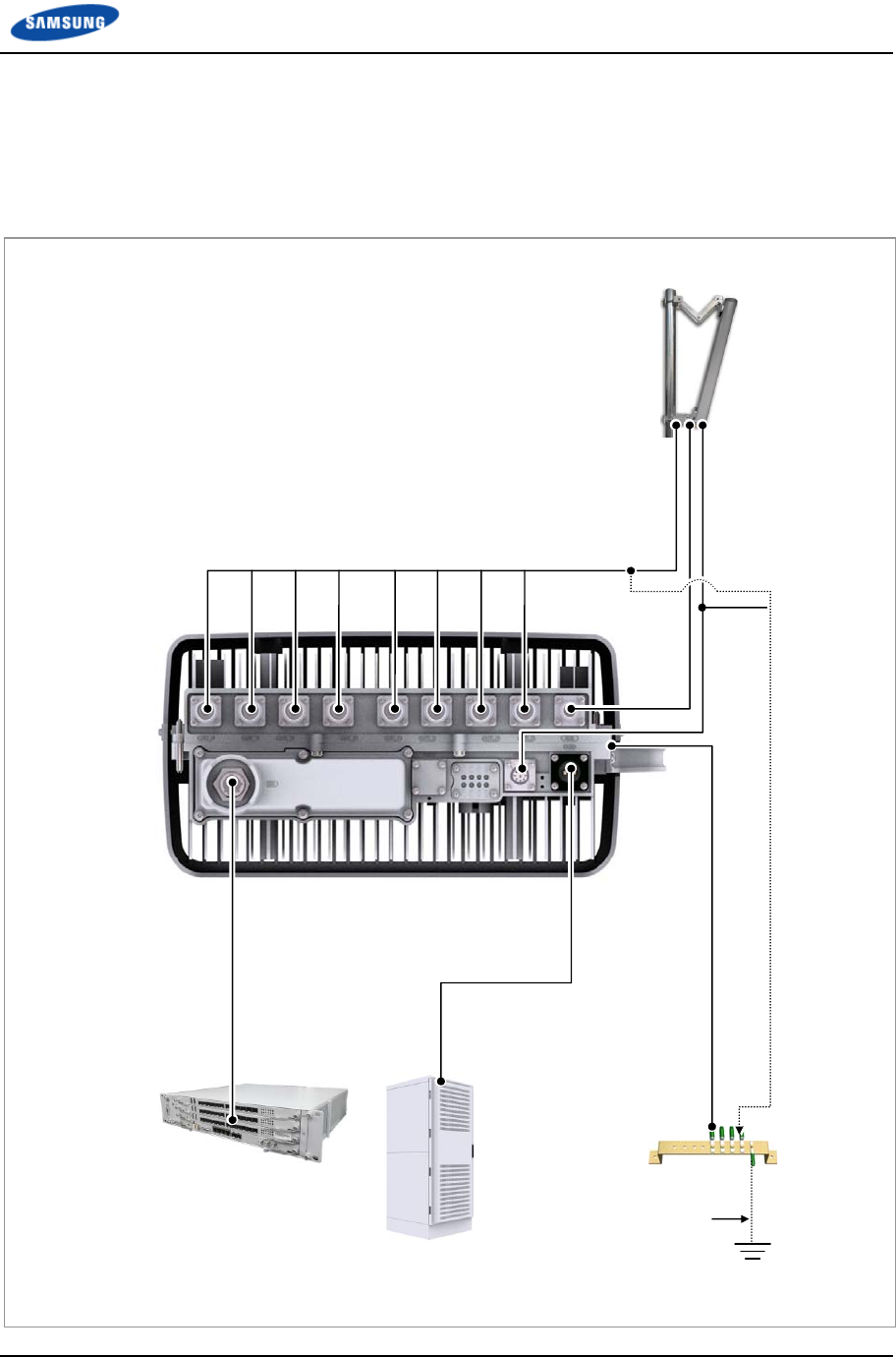
Figure 18. Cabling Diagram
[RF Antenna]
1) TGB Ground Cable
[TGB]
Feeder Line Ground Cable
(Ground Kit/7/8 in. Feeder Line or more)
※ TGB and Ground Kit are used in case of the 7/8 in. feeder line or more.
[Rectifier]
[UADU]
7) CPRI Cable
2) RF Cable
3) RET Cable
6) Power Cable
5) RRH-B8 Ground Cable
4) CAL Cable
Chapter 2 Installation of RRH-B8
Smart MBS RRH-B8 Installation Manual v3.0 34
©Samsung Proprietary and Confidential
Table 8. System Cabling
From To Cable
Underground
Ground
TGB
(Tower Ground Bar)
1 TGB Ground Cable
: AWG2, GV 25 mm2 × 1C
(However, This can be different, defending on the standard of
service provider)
RRH-B8 RF Antenna 2 RF Cable
: 1/2 in. or 7/8 in. Feeder Line
Mini Din-Male Connector (10 feet, 3 m; Site Dependant)
3 RET Cable (Shield Cable)
4 CAL Cable
: 1/2 in. or 7/8 in. Feeder Line
N Type-Male Connector (10 feet, 3 m; Site Dependant)
TGB 5 RRH-B8 Ground Cable
: AWG8, GV 6 mm2 × 1C
Rectifier 6 Power Cable
: AWG8,6 mm2 × 2C
UADU 7 CPRI Cable
: Optic Cable (Single Mode)
Refer to Annex C for connecting the tower grounding cable.
Chapter 2 Installation of RRH-B8
Smart MBS RRH-B8 Installation Manual v3.0 35
©Samsung Proprietary and Confidential
Connecting cable between RRH and Antenna
Connecting RF Cable
Follow the steps below to connect the RF cables between an RRH and an antenna.
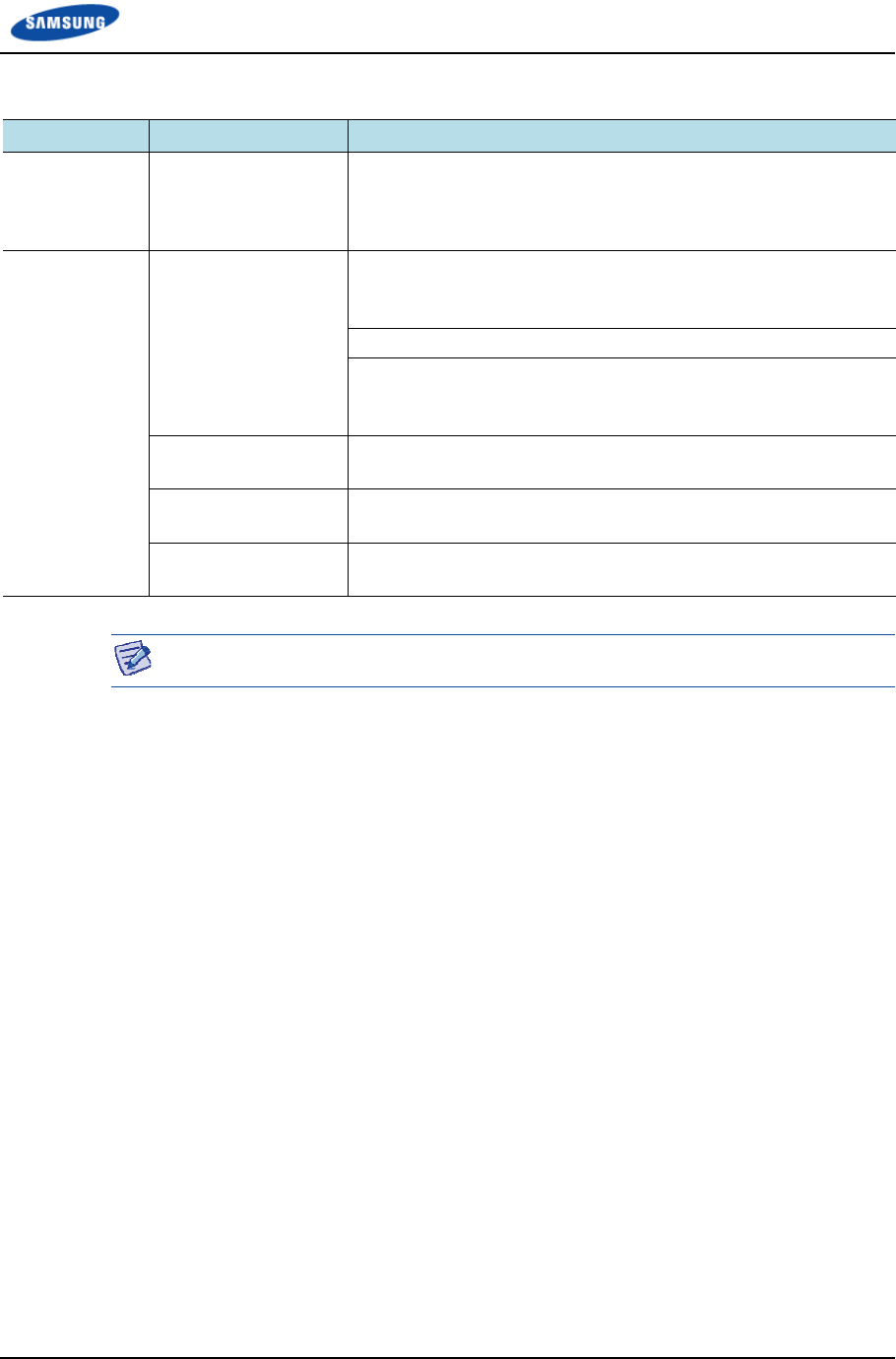
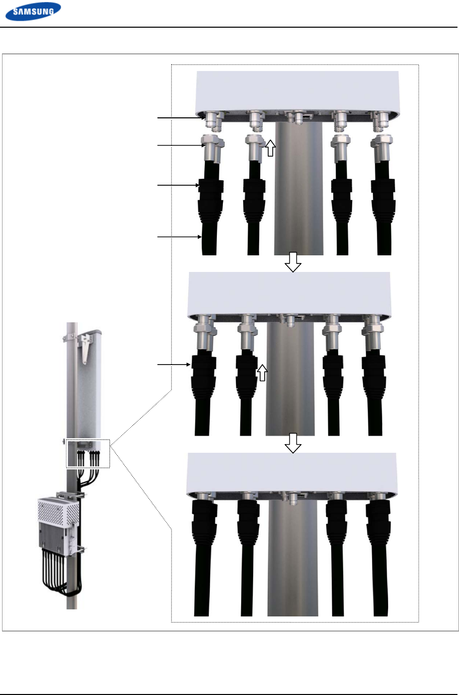
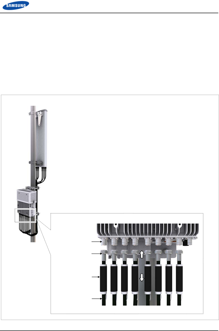
Type 1_Finishing Connection Part using the JMA Boots
1 Install the RF cable assemblies from the RRH-B8 to the RF antenna ports.
(JMA boots are inserted at both ends of the RF cable assemblies.)
o Connector on the RRH side: Mini Din Type-Male
o Connector on the RF antenna side: Mini Din Type-Male
2 Connect the connectors that are attached at the ends of the RRH-B8 side cables
to the ANT_0~7 ports of RRH-B8.
Figure 19. Connecting RF Cable_Type 1 (1)
JMA Boots
Mini Din Type-Male
Connector
ANT Port
(Mini Din Type-Female)
RF Cable
Chapter 2 Installation of RRH-B8
Smart MBS RRH-B8 Installation Manual v3.0 36
©Samsung Proprietary and Confidential
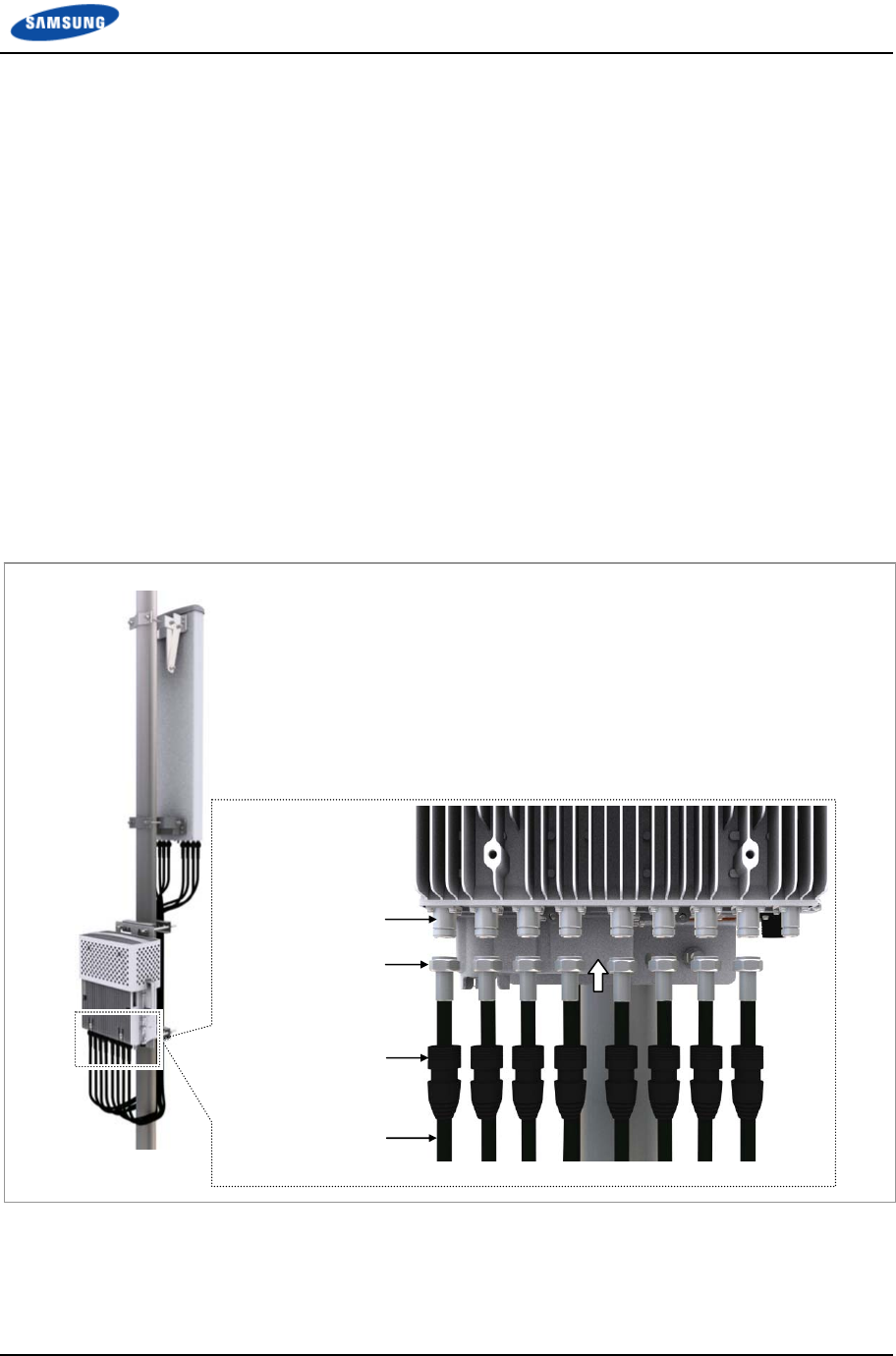
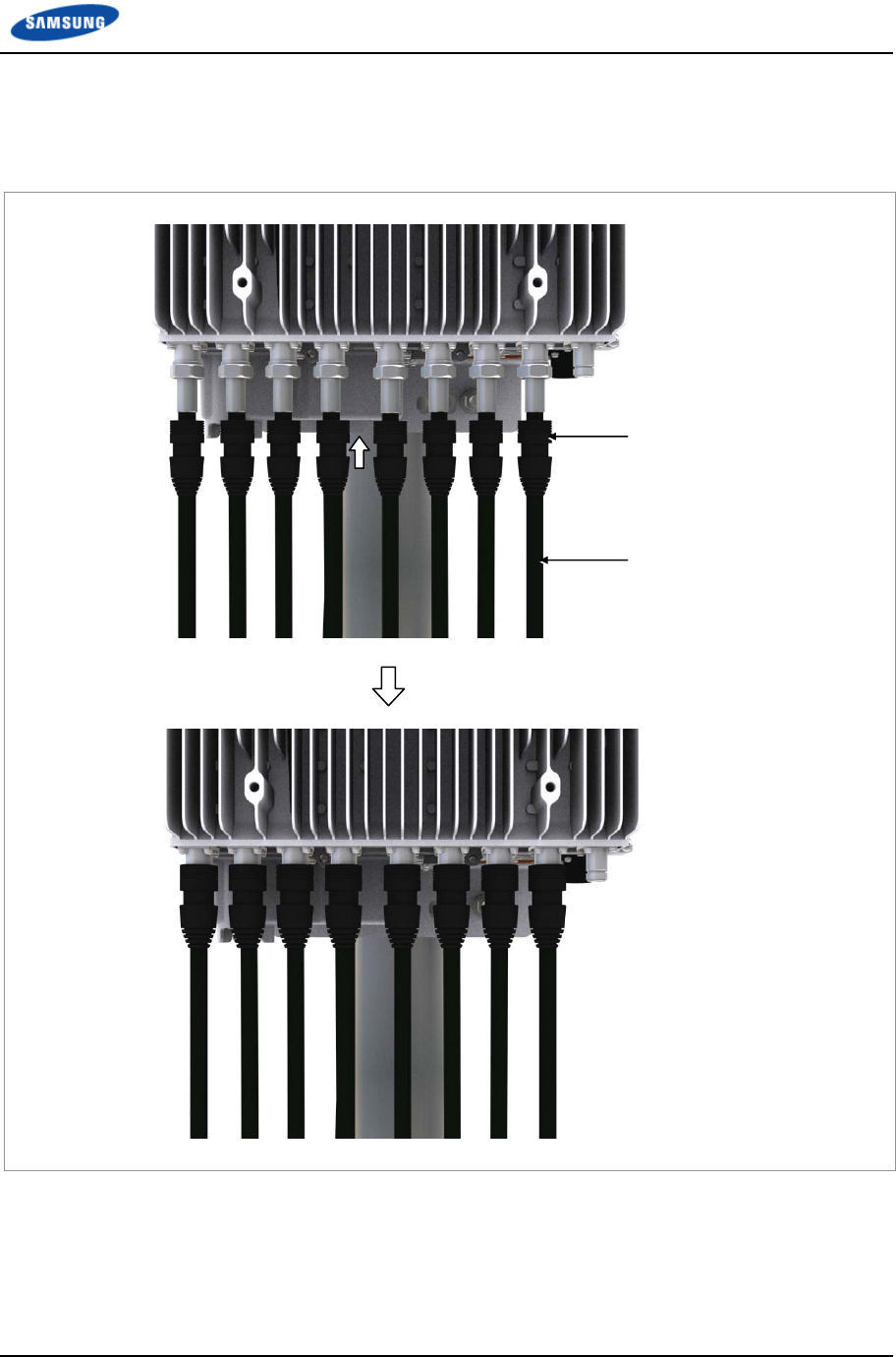
3 After connecting the connectors, push up the JMA boots to the connector
connection parts.
Figure 20. Connecting RF Cable_Type 1 (2)
4 Connect the connectors assembled at the ends of RF antenna side cables to the
antenna input ports.
5 After connecting the connectors, push up the JMA boots to the connector
connection parts.
JMA Boots
RF Cable
Chapter 2 Installation of RRH-B8
Smart MBS RRH-B8 Installation Manual v3.0 37
©Samsung Proprietary and Confidential
Figure 21. Connecting RF Cable_Type 1 (3)
Antenna Input Port
(Mini Din Type-Female)
Mini Din Type-Male
RF Cable
JMA Boots
JMA Boots
Chapter 2 Installation of RRH-B8
Smart MBS RRH-B8 Installation Manual v3.0 38
©Samsung Proprietary and Confidential
Type 2_Finishing using the Cold Shrink Tube
1 Install the RF cable assemblies from the RRH-B8 to the RF antenna ports.
o Connector on the RRH side: Mini Din Type-Male
o Connector on the RF antenna side: Mini Din Type-Male
2 Insert cold shrink tubes at the ends of the RRH-B8 side cables.
3 Connect the connectors that are attached at the ends of the RRH-B8 side cables
to the ANT_0~7 ports of RRH-B8.
Figure 22. Connecting RF Cable_Type 2 (1)
Mini Din Type-Male
Connector
ANT Port
(Mini Din Type-Female)
RF Cable
Cold Shrink Tube

Chapter 2 Installation of RRH-B8
Smart MBS RRH-B8 Installation Manual v3.0 39
©Samsung Proprietary and Confidential
4 After connecting the connectors, place the cold shrink tubes to the connector
connection parts.
5 Hold one side of the cold shrink tube with a hand to make it unmovable and
shrink the tube by pulling downward the lead wire.
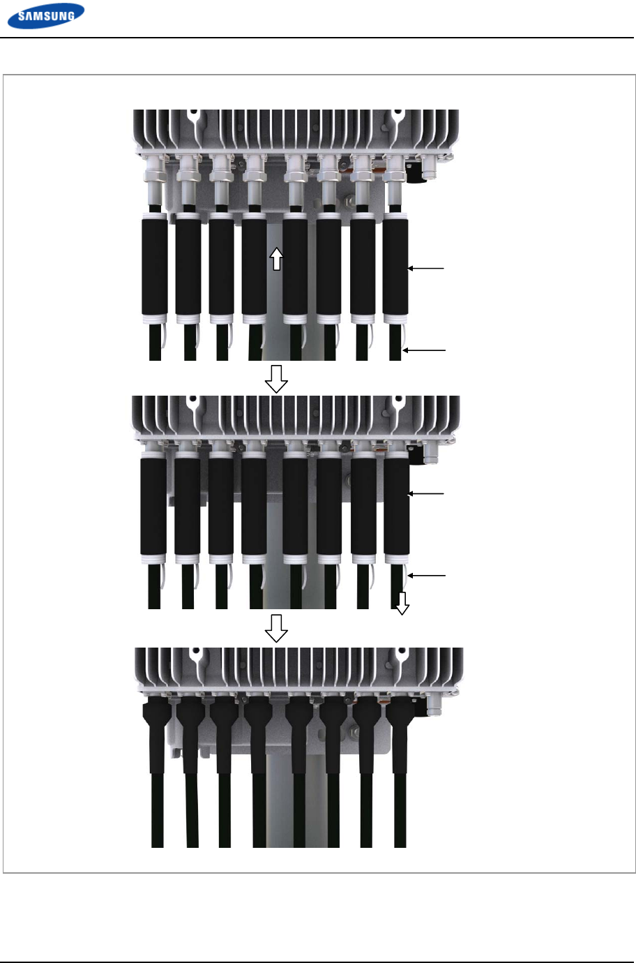
Chapter 2 Installation of RRH-B8
Smart MBS RRH-B8 Installation Manual v3.0 40
©Samsung Proprietary and Confidential
Figure 23. Connecting RF Cable_Type 2 (2)
6 Insert cold shrink tubes at the ends of the RF antenna side cables for finishing
and connect the connectors to the antenna input ports.
RF Cable
Cold Shrink Tube
Cold Shrink Tube
Lead wire
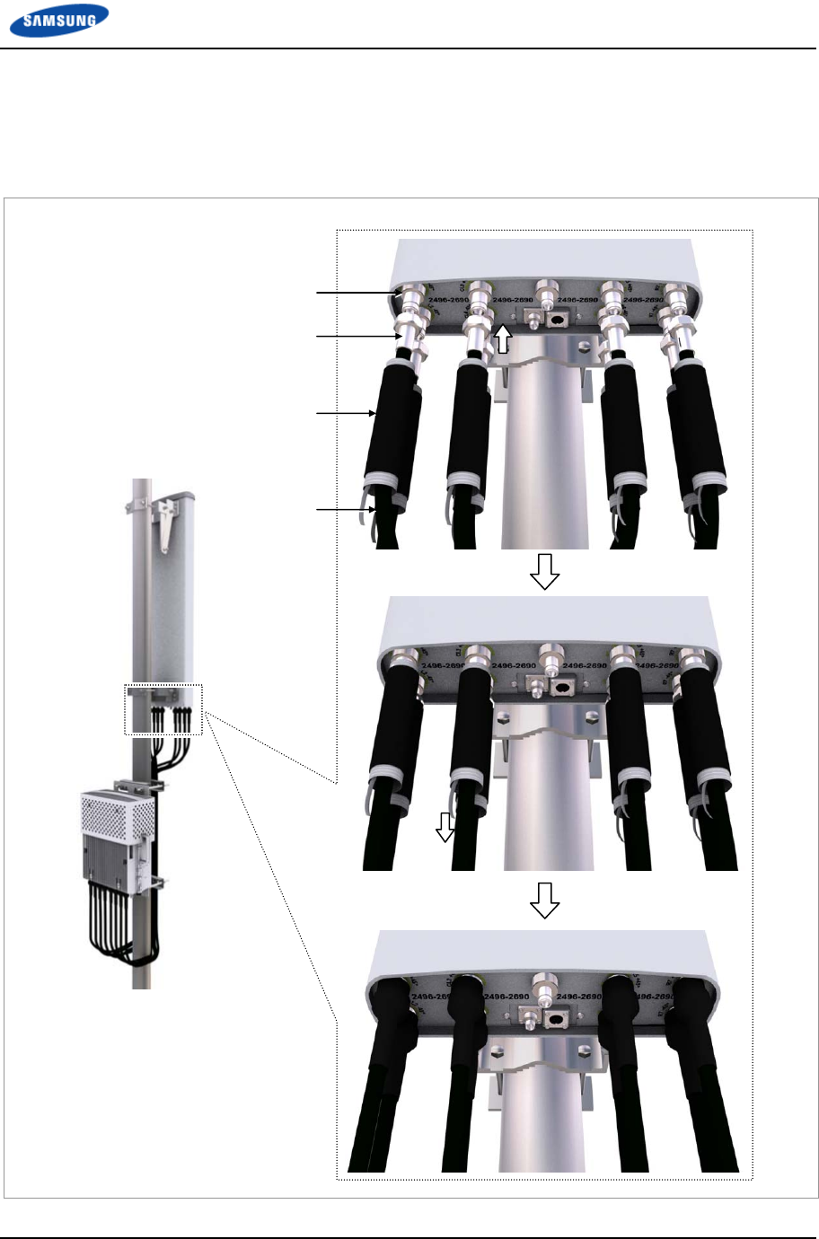
Chapter 2 Installation of RRH-B8
Smart MBS RRH-B8 Installation Manual v3.0 41
©Samsung Proprietary and Confidential
7 After connecting the connectors, place the cold shrink tubes to the connector
connection parts and finish the connectors as the same method as the RRH-B8
side connectors.
Figure 24. Connecting RF Cable_Type 2 (3)
Antenna Input Port
(Mini Din Type-Female)
Mini Din Type-Male
RF Cable
Cold Shrink Tube
Chapter 2 Installation of RRH-B8
Smart MBS RRH-B8 Installation Manual v3.0 42
©Samsung Proprietary and Confidential
Table 9. RRH to Antenna Mapping (1Sector / RRH)
RRH Port Cable 8T8R Antenna Port
0 RF Cable 8
1 7
2 6
3 5
4 4
5 3
6 2
7 1
Table 10. RRH to Antenna Mapping (2Sector / RRH : 4T4R 2Sector)
RRH Port Cable 4T4R Antenna Port
0 RF Cable α sector - 4
1 α sector - 3
2 α sector - 2
3 α sector - 1
4 β sector - 4
5 β sector - 3
6 β sector - 2
7 β sector - 1
Table 11. RRH to Antenna Mapping (3Sector / RRH : 2T2R 3Sector)
RRH Port Cable 2T2R Antenna Port
0 RF Cable α sector - 2
1 α sector - 1
2 β sector - 2
3 β sector - 1
4 γ sector - 2
5 γ sector - 1
6 N/C
7 N/C
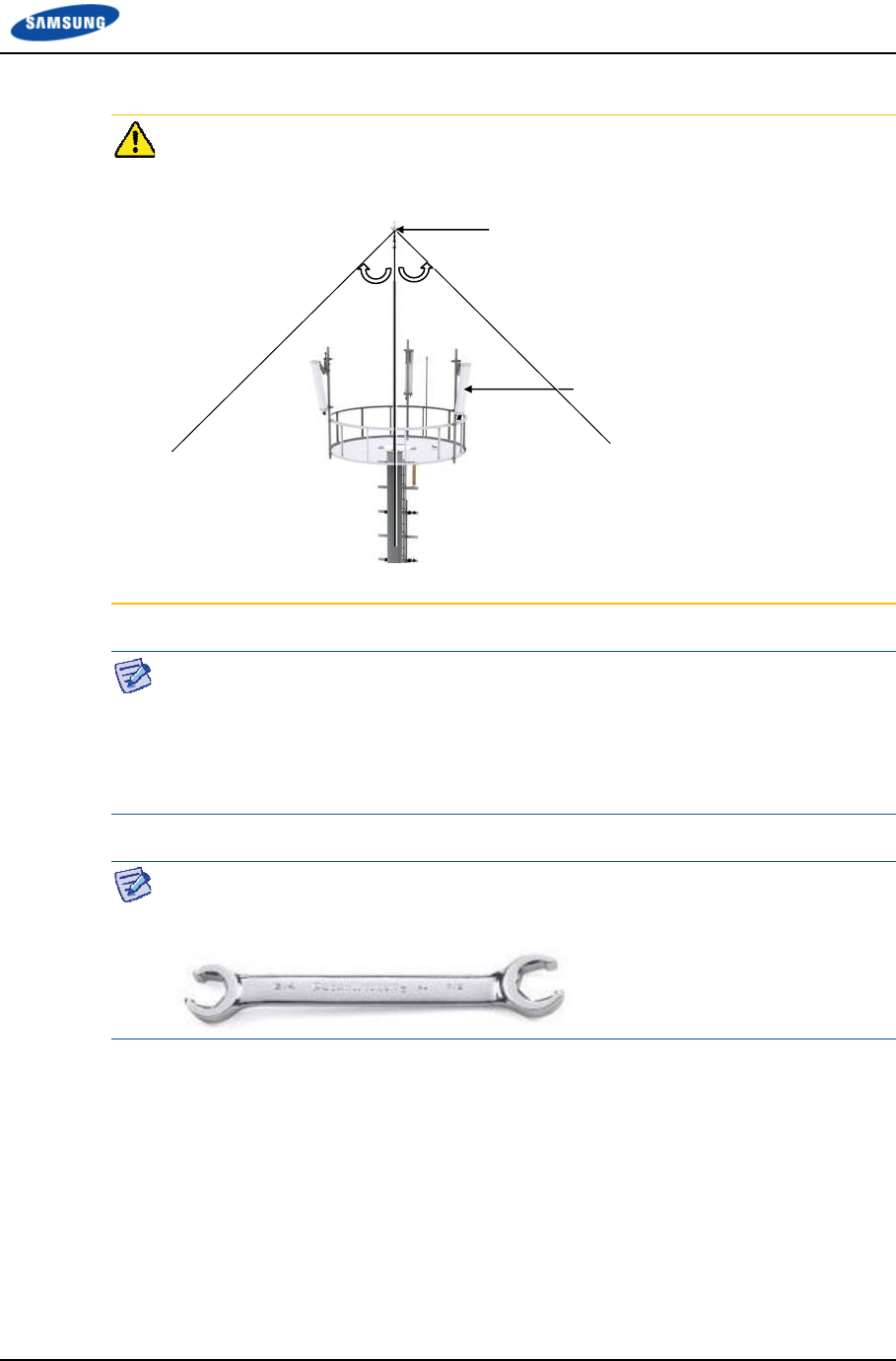
Chapter 2 Installation of RRH-B8
Smart MBS RRH-B8 Installation Manual v3.0 43
©Samsung Proprietary and Confidential
When you install the antenna, the antenna must be within the protective angle
(left/right side 45° each from the central axis) to prevent the antenna from
lightning damage.
Check whether the system is turned off before connecting or disconnecting an RF
cable connector to or from the RRH-B8 RF port and the RF antenna.
When connecting the RF cable between RRH-B8 RF port and RF antenna, each
port and the RF cable connector should be tighten by 8 lbf·ft (110.4 kgf·cm)
torque to minimize influence of PIMD.
Use a flare nut wrench (Hexagon: 7/8 in.) when connecting/disconnecting the RF
cable connector to/from RRH-B8 RF Port and RF Antenna.
Lightning rod
45°45°
RF Antenna
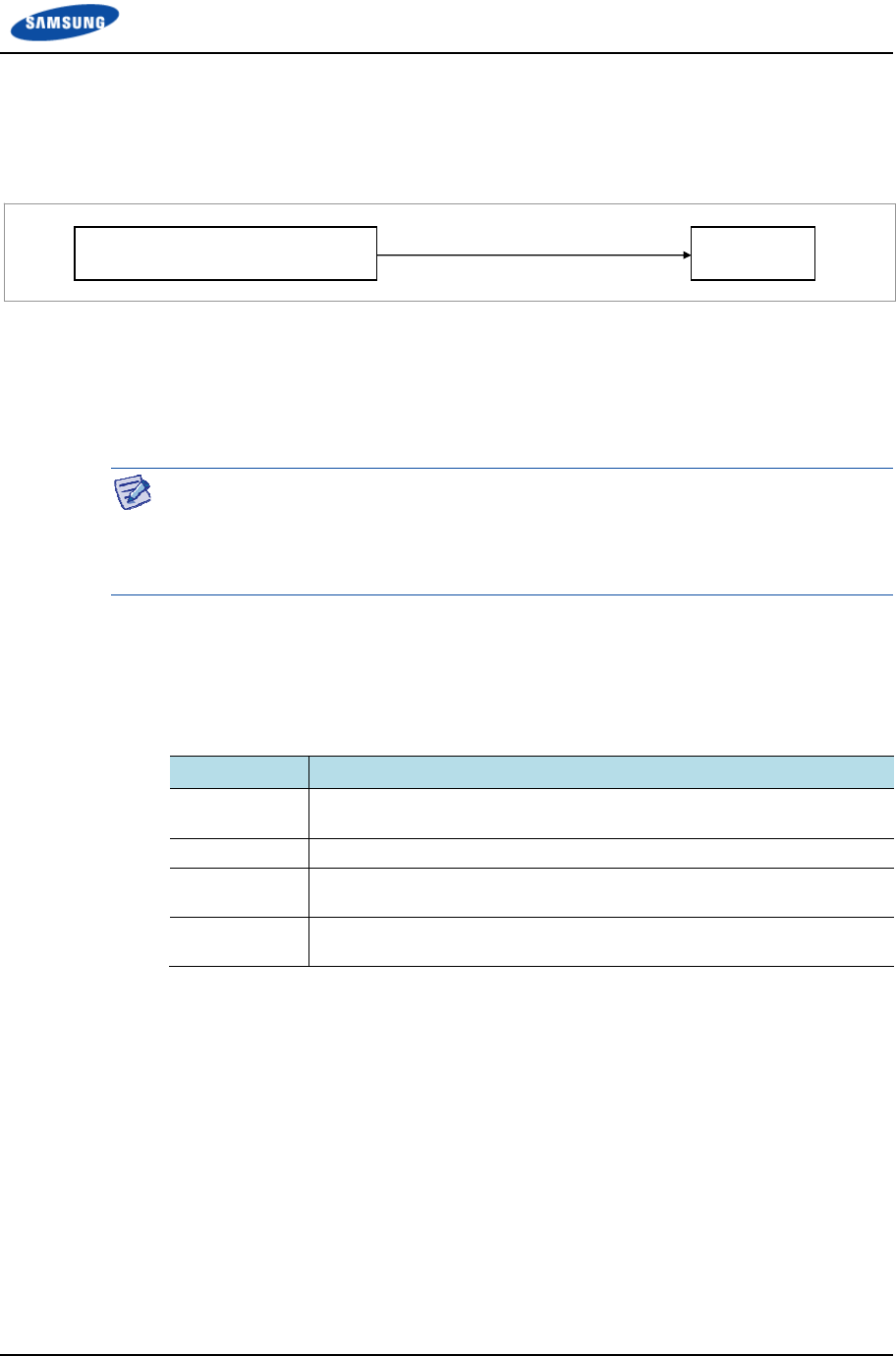
Chapter 2 Installation of RRH-B8
Smart MBS RRH-B8 Installation Manual v3.0 44
©Samsung Proprietary and Confidential
Checking Feeder line Connection
After connecting the feeder line, perform the continuity test and feeder cable return
loss to check if the feeder cable is changed and measure VSWR of antenna and
feeder cable.
Take measurements for the sections ①-② for all of the cables.
The standing wave ratio must be equal to or less than the reference value. If not,
the cable must be removed, measured for each section again, and necessary actions
be taken.
The voltage standing wave ratio (VSWR) of the cable and connector between the
system’s RF port to the antenna port must be smaller than 1.5 (return loss: 14 dB).
If a separate standard has been established with the career, the established standard
will take precedence.
Identification tag installation
Attach the identification tag in the below table to the feeder line.
Table 12. GPS Identification Tag of Feeder line
Category Description
Installation
position
Attach the identification tag to the both ends of the antenna.
Materials Use the material of aluminum coated by vinyl for the identification tag.
Fixing method Fix the feeder cable to the 2 holes on the identification tag with the
black cable tie.
Marking The markings must be prevented from being erased by using relief
engraving or coated labels.
Antenna
System’s external ‘I connector’
connection
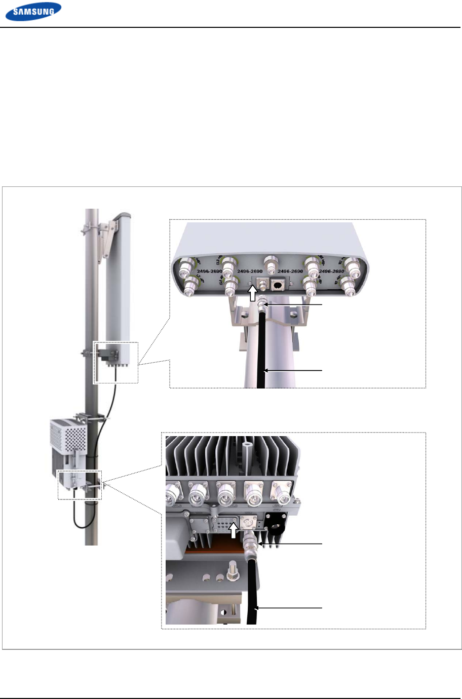
Chapter 2 Installation of RRH-B8
Smart MBS RRH-B8 Installation Manual v3.0 45
©Samsung Proprietary and Confidential
Connecting RET cable
Follow the steps below to connect the Remote Electrical Tilting (RET) cable used
to control the tilting angle of the antenna from the distance.
1 Connect the AISG Male connector of the RET cable assembly to the RET port
on the lower part of the RRH-B8.
2 Connect the AISG Female connector of the RET cable assembly to the RET
port on the lower part of the RF antenna.
Figure 25. Connecting RET cable
RET Cable (Shield Type)
A
ISG Female Connecto
r
RET Cable (Shield Type)
A
ISG Male Connecto
r
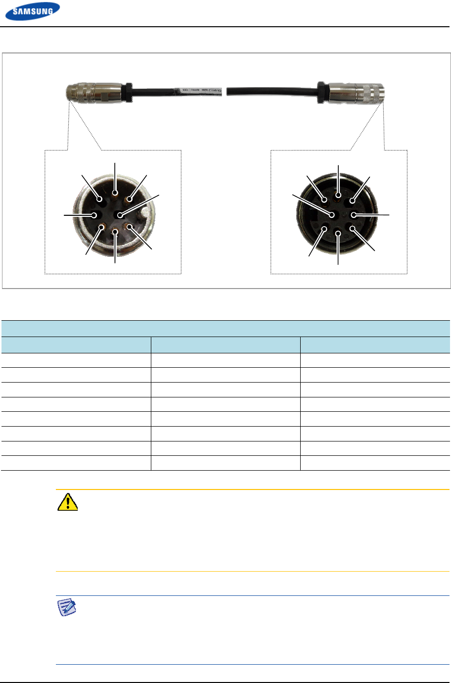
Chapter 2 Installation of RRH-B8
Smart MBS RRH-B8 Installation Manual v3.0 46
©Samsung Proprietary and Confidential
Figure 26. RET Cable Connector
Table 13. RET Cable-Side Connector Pin Map
Amphenol AISG Connector
Male Function Female
1 +12 V Optional (N.C) 1
2 N.C 2
3 RS485 B 3
4 RS485 GND 4
5 RS485 A 5
6 +21 V 6
7 +21 V RTN 7
8 N.C 8
Make sure to turn off the breaker connected to the RRH-B8 power of the DU
cabinet before connecting the RET cable between the antenna RET port and the
RRH-B8 RET port.
If you connect or disconnect the RET cable while the breaker is turned on, it may
cause an electric short circuit resulting in damage to the RET function.
When 21 VDC volts are applied, the current supplied to the RET from RRH-B8
must be 1 A or lower.
The exterior of the RET connector must be made of metal without vent hole or
other UL certified material.
[RRH-B8-side Connector: AISG Male] [Antenna-side Connector: AISG Female]
6
8
1
4
2
5
3
7
8
6
1
4
2
7
3
5

Chapter 2 Installation of RRH-B8
Smart MBS RRH-B8 Installation Manual v3.0 47
©Samsung Proprietary and Confidential
Connecting CAL Cable
Follow the steps below to connect the CAL (Calibration) cable.
Type 1_Finishing Connection Part using the JMA Boots
1 Install the CAL cable assembly from the RRH-B8 CAL port to the RF antenna
CAL port.
(JMA boots are inserted at both ends of the CAL cable assemblies.)
o Connector on the RRH side: N Type-Male
o Connector on the RF antenna side: N Type-Male
2 Connect the connectors that are attached at the ends of the RRH-B8 side cable
to the CAL port of RRH-B8.
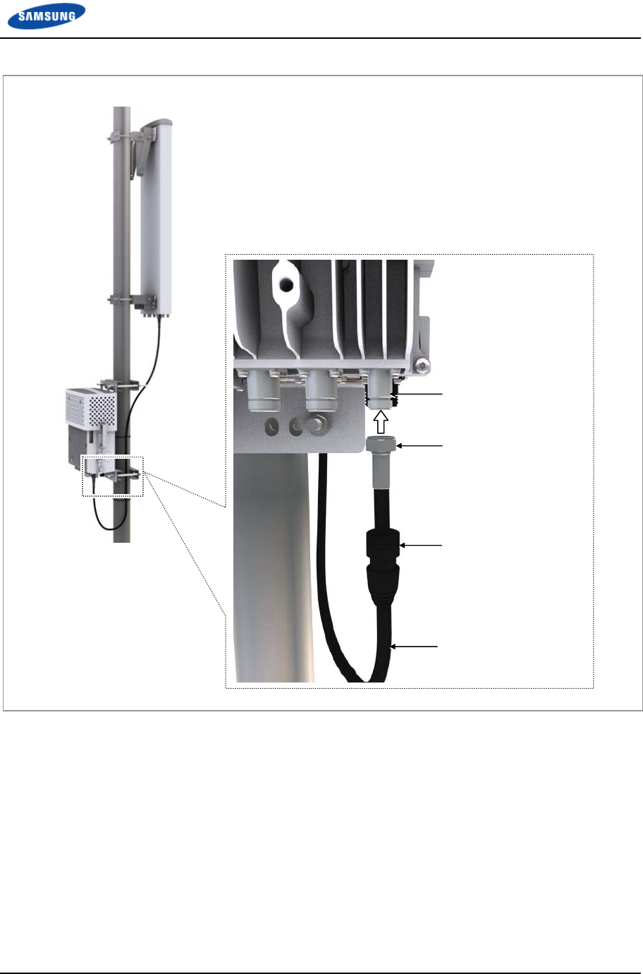
Chapter 2 Installation of RRH-B8
Smart MBS RRH-B8 Installation Manual v3.0 48
©Samsung Proprietary and Confidential
Figure 27. Connecting CAL Cable_Type 1 (1)
CAL Cable
CAL Port
N Type-Male Connector
JMA Boots
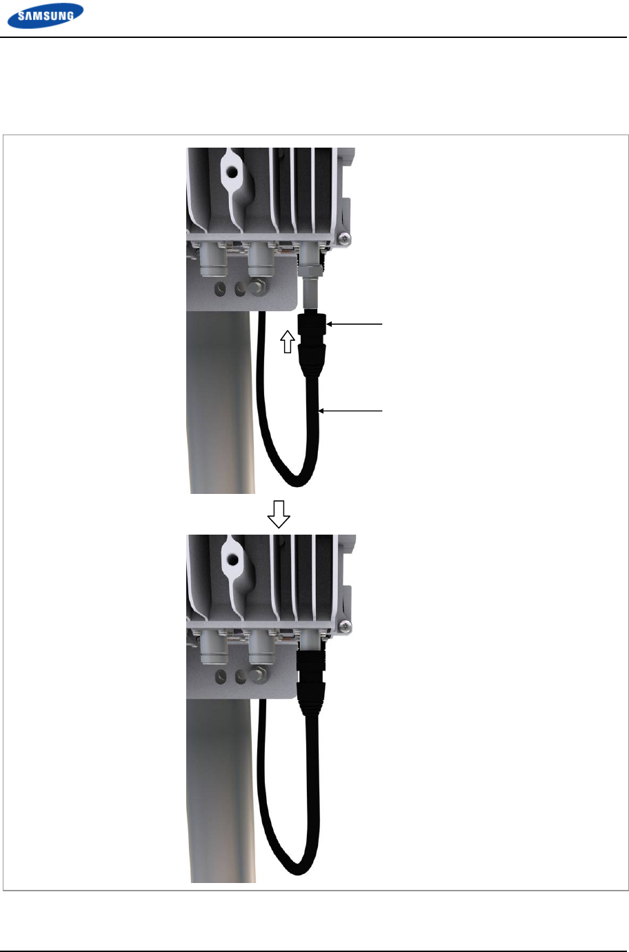
Chapter 2 Installation of RRH-B8
Smart MBS RRH-B8 Installation Manual v3.0 49
©Samsung Proprietary and Confidential
3 After connecting the connector, push up the JMA boots to the connector
connection part.
Figure 28. Connecting CAL Cable_Type 1 (2)
JMA Boots
CAL Cable

Chapter 2 Installation of RRH-B8
Smart MBS RRH-B8 Installation Manual v3.0 50
©Samsung Proprietary and Confidential
4 Connect the connector attached to the end of the RF antenna-side cable with
the CAL port of the antenna.
5 After connecting the connector, push up the JMA boots to the connector
connection part.
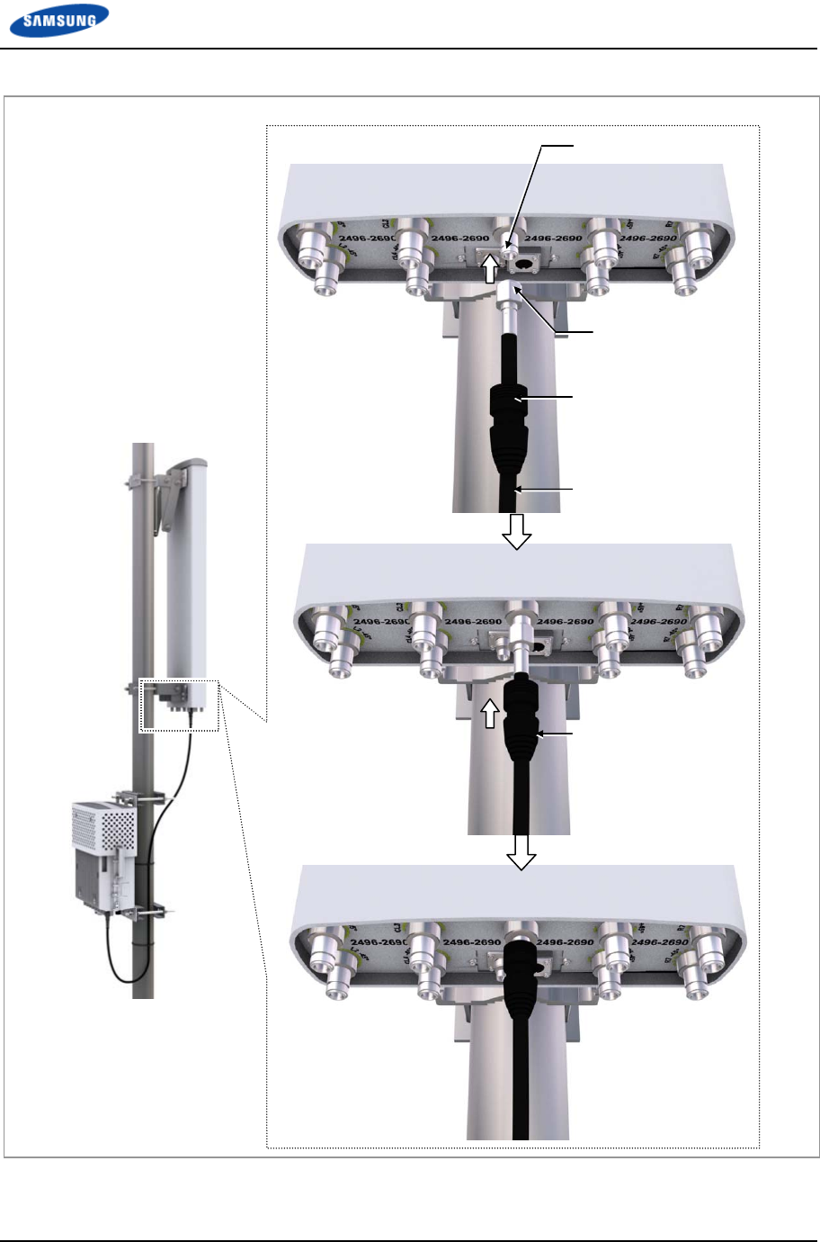
Chapter 2 Installation of RRH-B8
Smart MBS RRH-B8 Installation Manual v3.0 51
©Samsung Proprietary and Confidential
Figure 29. Connecting CAL Cable_Type 1 (3)
CAL Port (N Type-Female)
N Type-Male Connector
CAL Cable
JMA Boots
JMA Boots
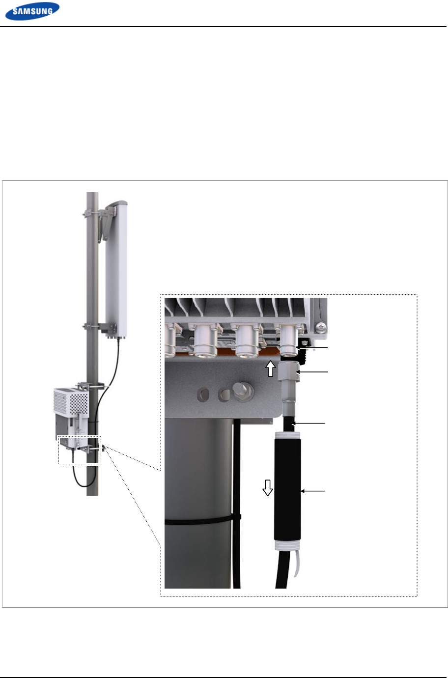
Chapter 2 Installation of RRH-B8
Smart MBS RRH-B8 Installation Manual v3.0 52
©Samsung Proprietary and Confidential
Type 2_Finishing using the Cold Shrink Tube
1 Install the CAL cable assembly from the RRH-B8 CAL port to the RF antenna
CAL port.
o Connector on the RRH side: N Type-Male
o Connector on the RF antenna side: N Type-Male
2 Insert cold shrink tube at the end of the RRH-B8 side cable for finishing and
connect the connector to the CAL port of RRH-B8.
Figure 30. Connecting CAL Cable_Type 2 (1)
CAL Cable
CAL Port
N Type-Male Connector
Cold Shrink Tube
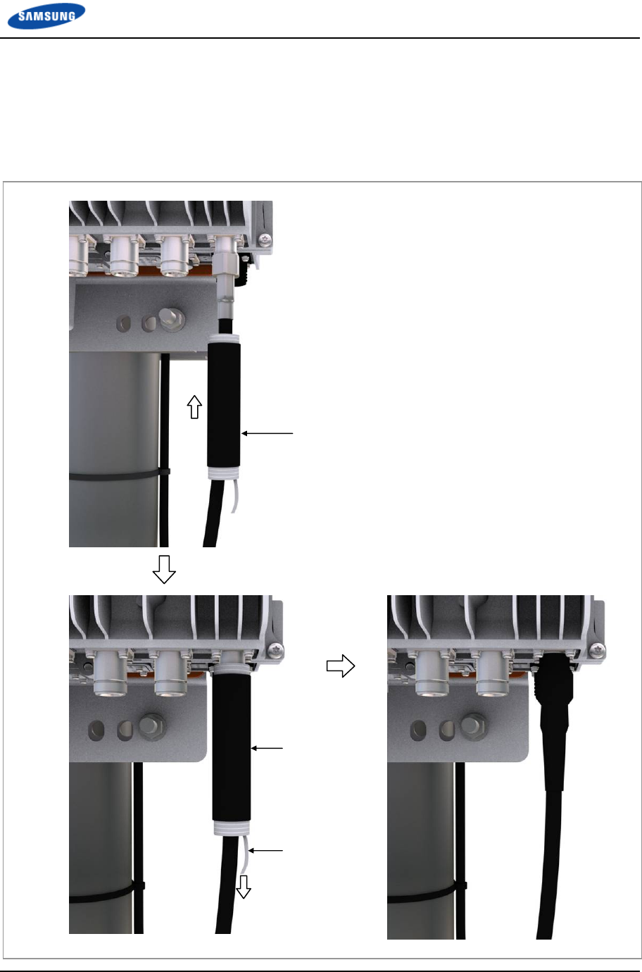
Chapter 2 Installation of RRH-B8
Smart MBS RRH-B8 Installation Manual v3.0 53
©Samsung Proprietary and Confidential
3 After connecting the connector, place the cold shrink tube to the connector
connection part.
4 Hold one side of the cold shrink tube with a hand to make it unmovable and
shrink the tube by pulling downward the lead wire.
Figure 31. Connecting CAL Cable_Type 2 (2)
Cold Shrink Tube
Lead Wire
Cold Shrink Tube

Chapter 2 Installation of RRH-B8
Smart MBS RRH-B8 Installation Manual v3.0 54
©Samsung Proprietary and Confidential
5 Insert cold shrink tube at the end of the RF antenna side cable for finishing and
connect the connector to the antenna CAL port.
6 After connecting the connector, place the cold shrink tube to the connector
connection part.
7 Hold one side of the cold shrink tube with a hand to make it unmovable and
shrink the tube by pulling downward the lead wire.
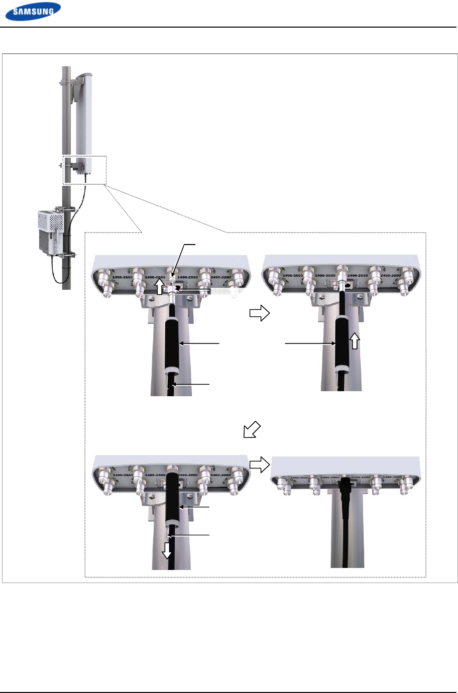
Chapter 2 Installation of RRH-B8
Smart MBS RRH-B8 Installation Manual v3.0 55
©Samsung Proprietary and Confidential
Figure 32. Connecting CAL Cable_Type 2 (3)
Cold Shrink Tube
CAL Port (N Type-Female)
CAL Cable
N Type-Male
Lead Wire
Cold Shrink Tube
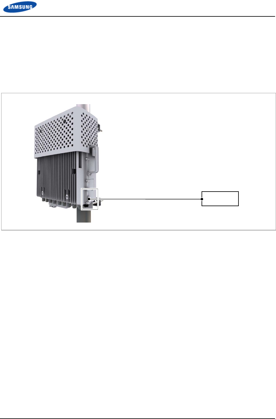
Chapter 2 Installation of RRH-B8
Smart MBS RRH-B8 Installation Manual v3.0 56
©Samsung Proprietary and Confidential
Connecting Ground Cable
Follow the steps below to connect the RRH-B8 ground cable.
1 Install one ground cable (AWG8, GV 6 mm2 × 1 C) from TGB to the ground
terminal at the right of RRH-B8.
Figure 33. Connecting Ground Cable (1)
2 Install the pressure terminal and the heat shrink tube at the end of the cable.
o Pressure Terminal: 6 mm2, 2 hole, Hole Diameter: 1.4 in. (6.3 mm), Hole
Distance: 0.63 in. (16 mm)
3 Place the pressure terminal at one end of the ground cable of RRH-B8 aligning
with the fixing holes and fix it using M6 SEMS. (When being tighten by screw,
apply 2.76~3.37 lbf.ft (38.16~46.64 kgf.cm) torque.)
RRH-B8 Ground Cable [TGB]
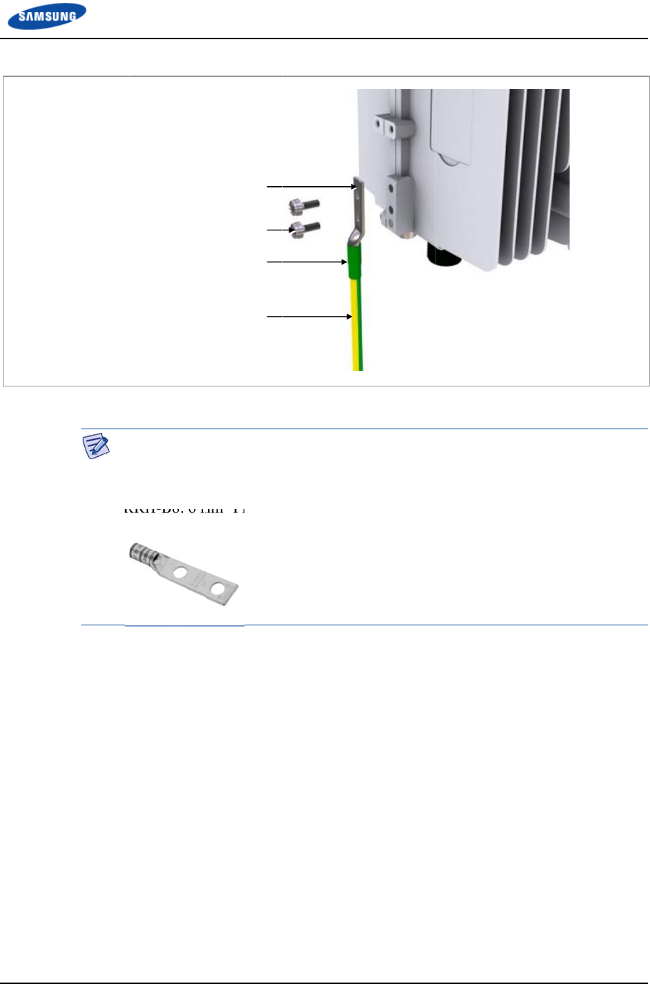
Smart M
B
©Samsu
n
Figure 3
4
B
S RRH-B8 I
n
n
g Proprietar
y
4
. Connectin
A
s
E
R
Ground Cabl
e
Fro
m
(2H
n
stallation Ma
y
and Confide
n
g Ground C
a
A
s for the pr
e
hould be us
e
E
x) Manufa
c
R
RH-B8: 6
m
M6
×
e
(AWG8, GV
6
m
TGB (Tower
G
Heat Shrink T
u
6 mm
2
Pressu
ole, Hole Diam
e
Hole Distan
c
n
ual v3.0
n
tial
a
bl
e
(2)
e
ssure termi
n
e
d.
c
ture
r
-Pand
u
m
m2 Pressur
e
10L SEMS
6
mm
2
× 1C)
G
round Bar)
u
be (Green)
re Terminal
e
ter: 1/4 in.,
c
e: 0.63 in.)
n
al or the ca
b
u
i
t
e
Terminal (
L
b
le,
t
he UL
L
L
CD8-14A-
L
Chapter 2 I
L
isted produ
c
L
)
I
nstallation
o
c
ts or equiv
a
f
RRH-B8
57
a
lent
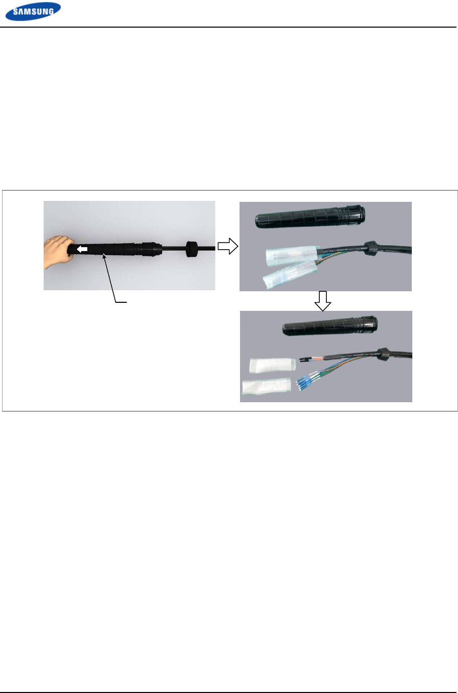
Chapter 2 Installation of RRH-B8
Smart MBS RRH-B8 Installation Manual v3.0 58
©Samsung Proprietary and Confidential
Connecting Power Cable
Follow the steps below to connect the power cable to RRH-B8.
Type 1_Using Hybrid Cable
1 Disassemble the water-proof cap from the Hybrid cable (blue group, white
group).
Figure 35. Connecting Power Cable_Type 1 (1)
Water-Proof Cap
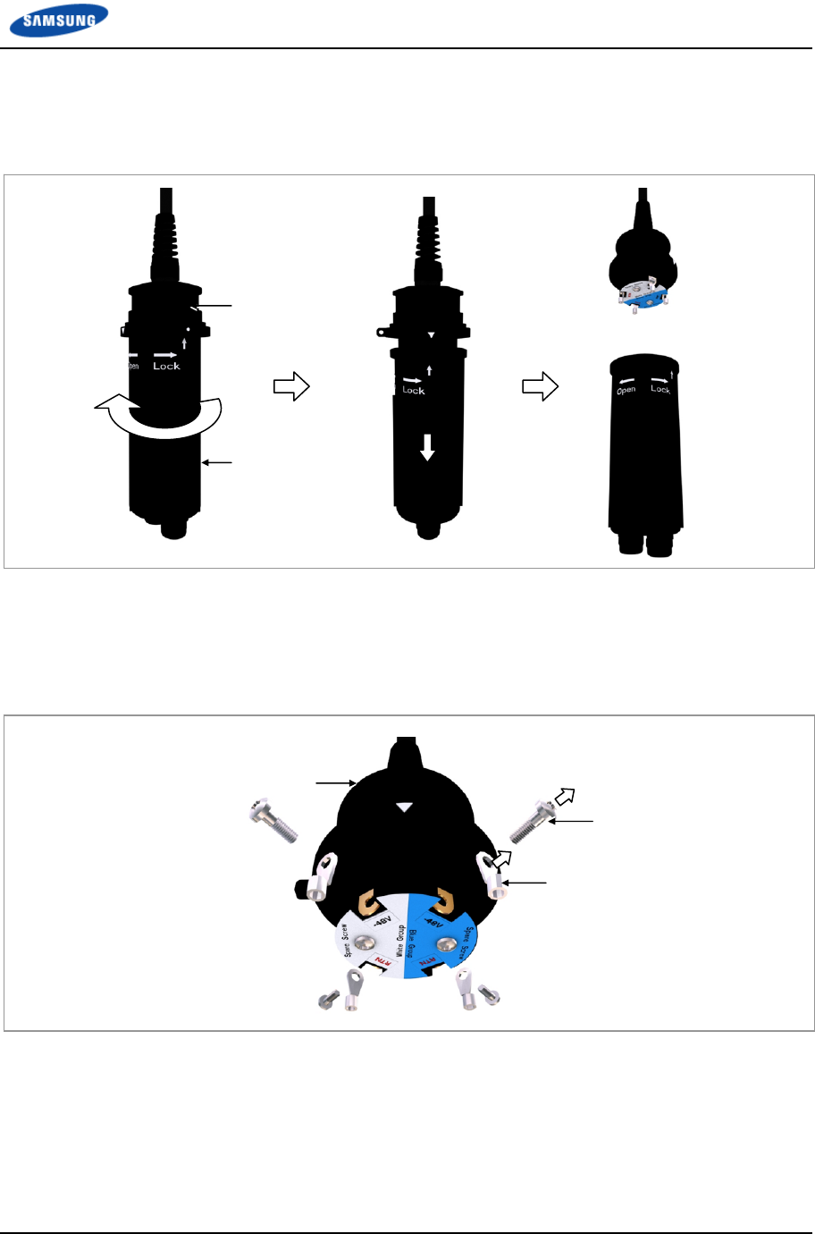
Chapter 2 Installation of RRH-B8
Smart MBS RRH-B8 Installation Manual v3.0 59
©Samsung Proprietary and Confidential
2 Disassemble the junction cylinder body and cap by pulling down the junction
cylinder cap after rotating the cap to open.
Figure 36. Connecting Power Cable_Type 1 (2)
3 Disassemble the ring type terminals by removing the M6 screws fixed on the
power connection terminals of junction cylinder body. (Be careful not to lose
the removed M6 screws.)
Figure 37. Connecting Power Cable_Type 1 (3)
Ring Type Terminal
Junction Cylinder Bod
y
M6 Screw
Junction Cylinder Cap
Junction Cylinder Body
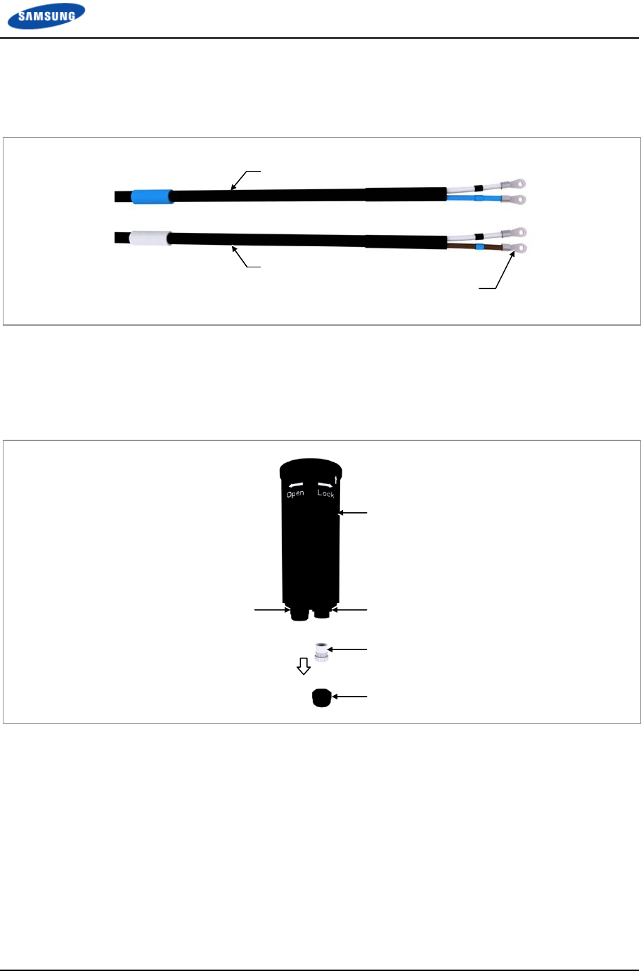
Chapter 2 Installation of RRH-B8
Smart MBS RRH-B8 Installation Manual v3.0 60
©Samsung Proprietary and Confidential
4 Attach the disassembled ring type terminals to the blue group/white group
power cables.
Figure 38. Connecting Power Cable_Type 1 (4)
5 Disassemble the cable gland nut and water-proof filler for the blue group
power cable inlet at the bottom of junction cylinder cap. (Be careful not to lose
the removed cable gland nut and water-proof filler.)
Figure 39. Connecting Power Cable_Type 1 (5)
Junction Cylinder Cap
Cable Gland Nut
Cable Gland (for White Group) Cable Gland (for Blue Group)
Water-proof Filler
Power Cable (Blue Group)
Power Cable (White Group)
Ring Type Terminal
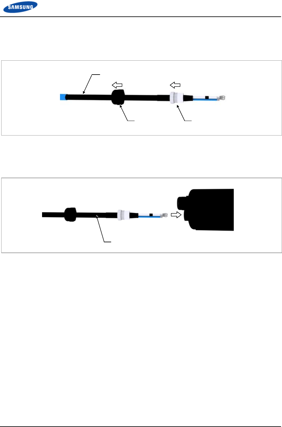
Chapter 2 Installation of RRH-B8
Smart MBS RRH-B8 Installation Manual v3.0 61
©Samsung Proprietary and Confidential
6 Insert the removed cable gland nut and water-proof filler to the blue group
power cable.
Figure 40. Connecting Power Cable_Type 1 (6)
7 Insert the blue group power cable through the cable gland hole (blue group) of
junction cylinder cap.
Figure 41. Connecting Power Cable_Type 1 (7)
Power Cable (Blue Group)
Power Cable (Blue Group)
Cable Gland Nut Water-proof Filler
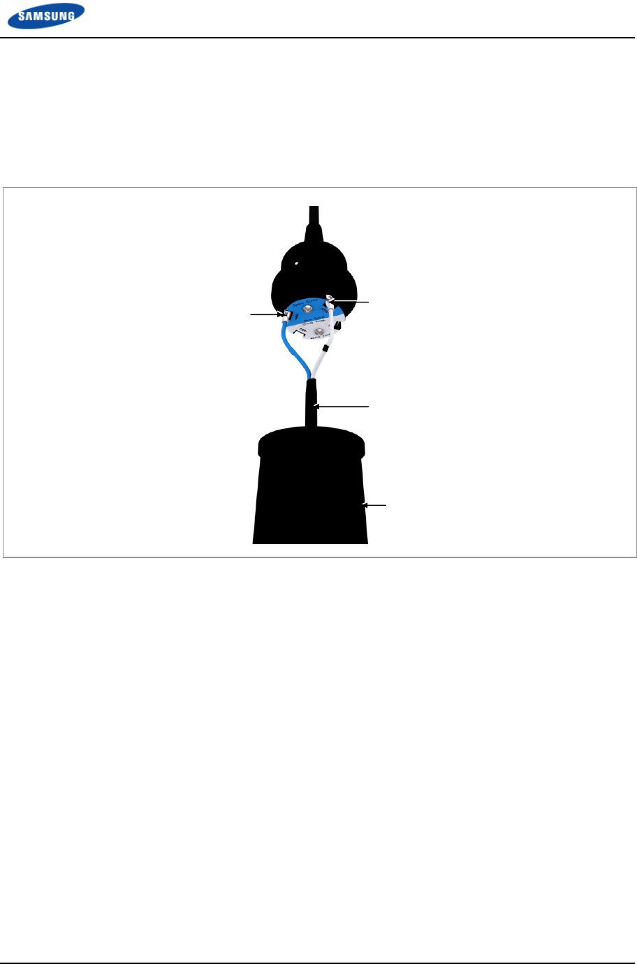
Chapter 2 Installation of RRH-B8
Smart MBS RRH-B8 Installation Manual v3.0 62
©Samsung Proprietary and Confidential
8 Fix the ring type terminals of power cable to the power connection terminal
(blue group) at the junction cylinder body according to the polarities. (-48 V:
blue, RTN: white/blue strip)
※ Power terminal block screw torque: 1.01 lbf·ft (14 kgf·cm)
Figure 42. Connecting Power Cable_Type 1 (8)
RTN
-48V
Power Cable (Blue Group)
Junction Cylinder Cap
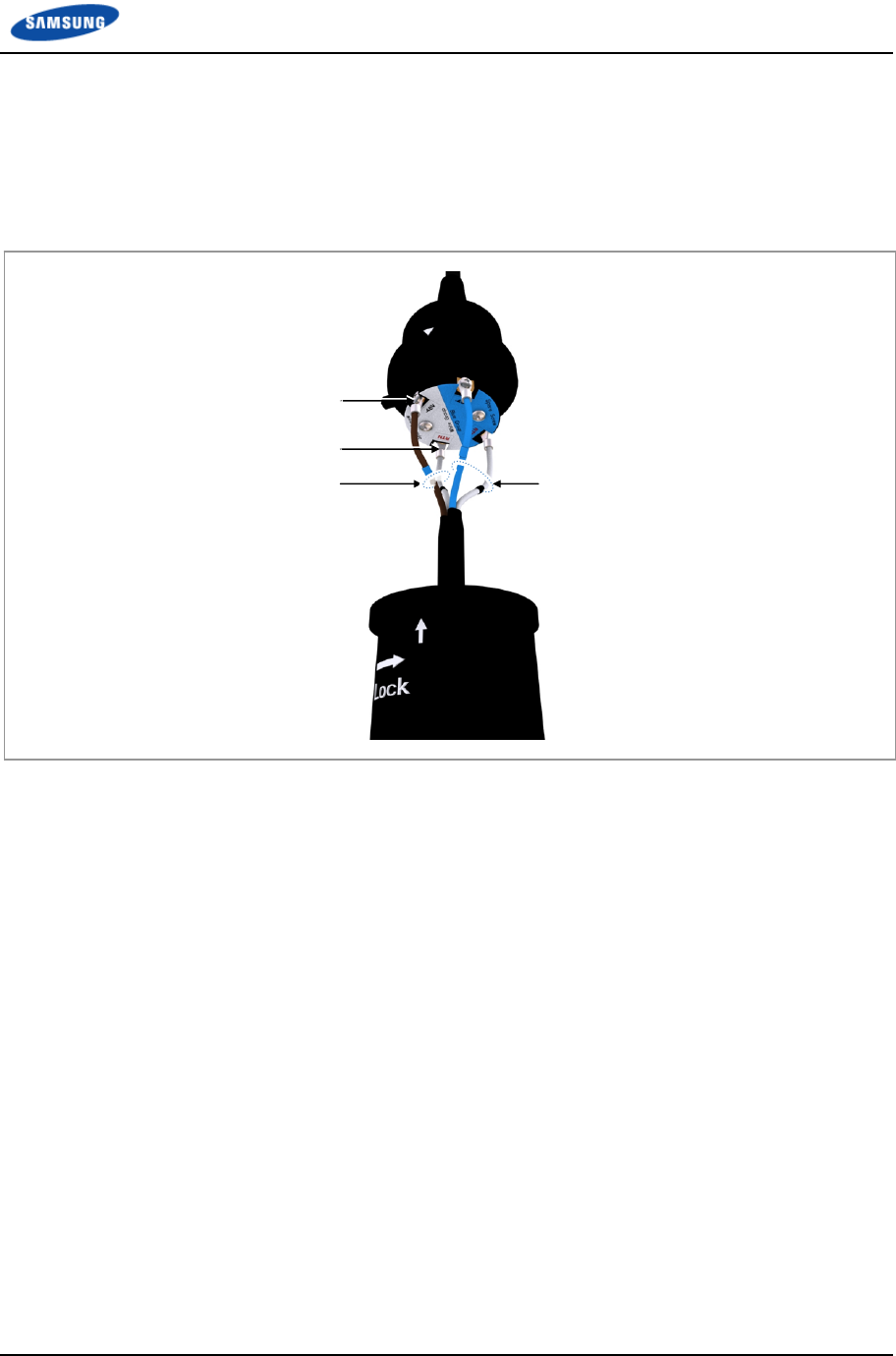
Chapter 2 Installation of RRH-B8
Smart MBS RRH-B8 Installation Manual v3.0 63
©Samsung Proprietary and Confidential
9 After working for the white group power cable as the same procedures 5)~7)
and fix the ring type terminals of power cable to the power connection
terminal (white group) at the junction cylinder body according to the polarities.
(-48 V: brown, RTN: white/brown strip)
Figure 43. Connecting Power Cable_Type 1 (9)
-48V
RTN
Power Cable (White Group) Power Cable (Blue Group)
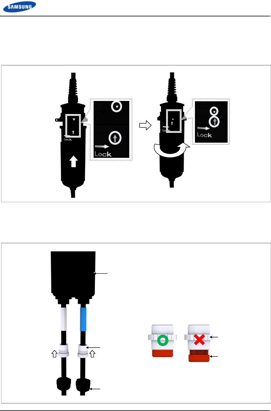
Chapter 2 Installation of RRH-B8
Smart MBS RRH-B8 Installation Manual v3.0 64
©Samsung Proprietary and Confidential
10 Insert the junction cylinder body and cap with aligning the ▽ and ↑ marks,
and rotate the cap to lock until the ○ and ↑ marks are aligned
Figure 44. Connecting Power Cable_Type 1 (10)
11 Push up the water-proof fillers inserted to the power cables to fit in the cable
gland body.
Figure 45. Connecting Power Cable_Type 1 (11)
Water-proof Filler
Water-proof Filler
Cable Gland Body
Junction Cylinder Cap
Cable Gland Nut
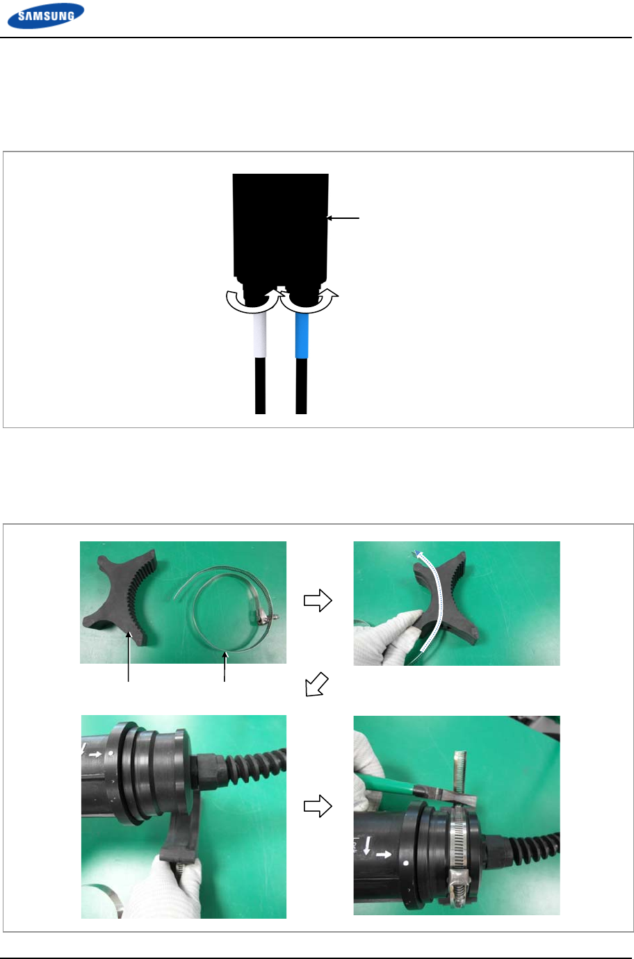
Chapter 2 Installation of RRH-B8
Smart MBS RRH-B8 Installation Manual v3.0 65
©Samsung Proprietary and Confidential
12 Fasten the cable gland nut to the cable gland body.
※ Cable gland nut torque: 4.43 lbf·ft (61.2 kgf·cm)
Figure 46. Connecting Power Cable_Type 1 (12)
13 Fix the mount to the junction cylinder body using a steel band and cut the
remain part using a nipper or plier.
Figure 47. Connecting Power Cable_Type 1 (13)
Mount Steel Band
Junction Cylinder Cap
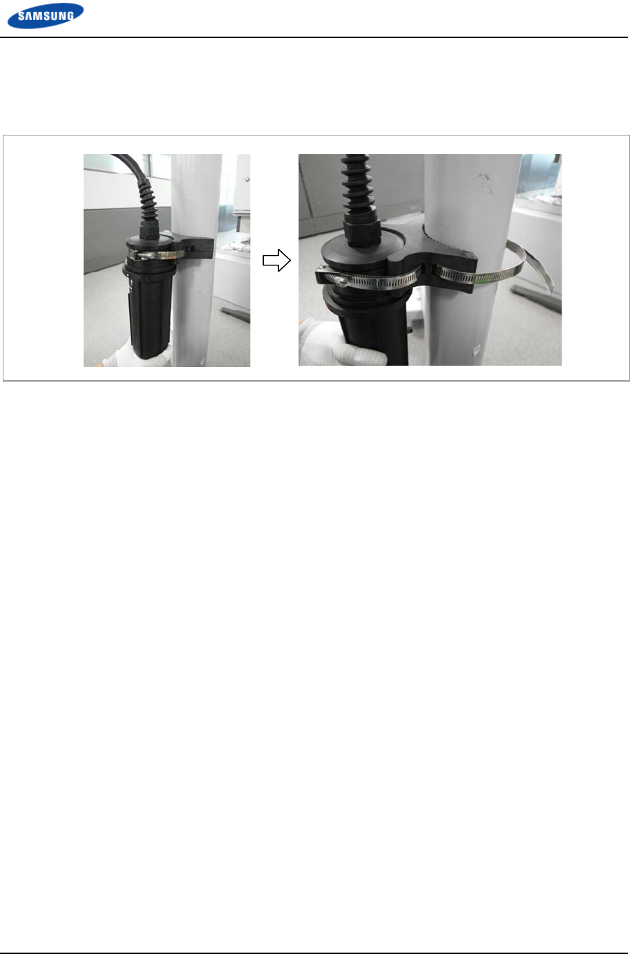
Chapter 2 Installation of RRH-B8
Smart MBS RRH-B8 Installation Manual v3.0 66
©Samsung Proprietary and Confidential
14 Place the fixed mount of junction cylinder to the pole and fix it using a steel
band.
Figure 48. Connecting Power Cable_Type 1 (14)
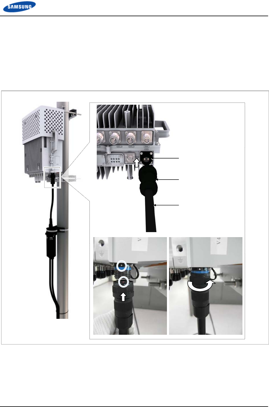
Chapter 2 Installation of RRH-B8
Smart MBS RRH-B8 Installation Manual v3.0 67
©Samsung Proprietary and Confidential
15 Install the power cable, which is connected to the junction cylinder, to the
power input port (PWR).
16 Insert the DC power connector after aligning the mark of power cable
connector and ○ mark of RRH-B8 power input port connector.
17 Fasten the nut of cable side connector until the clicking sound is not heard.
Figure 49. Connecting Power Cable_Type 1 (15)
Power Input Port (PWR)
DC Power Connector
RRH Power Cable
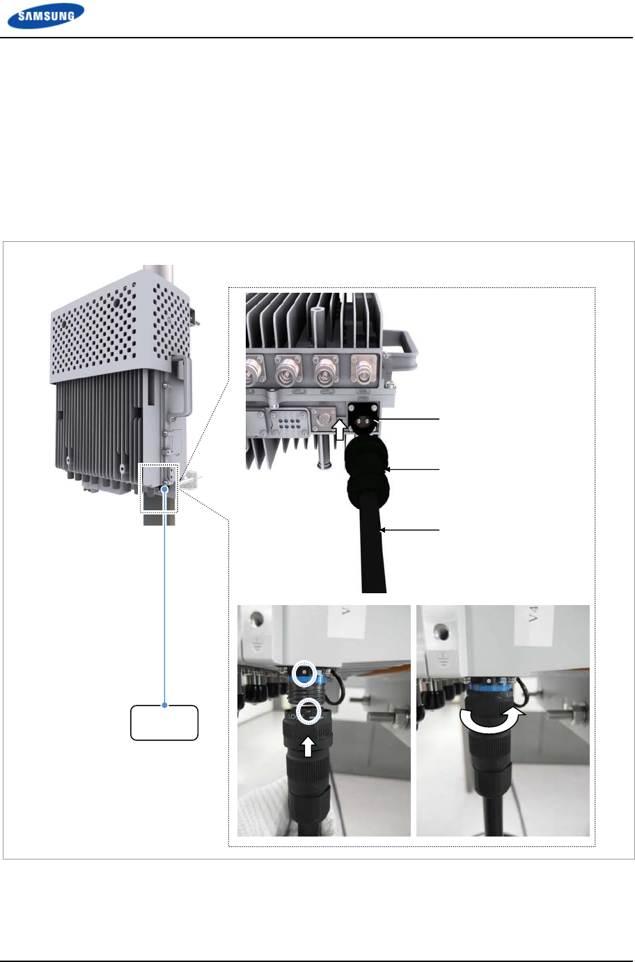
Chapter 2 Installation of RRH-B8
Smart MBS RRH-B8 Installation Manual v3.0 68
©Samsung Proprietary and Confidential
Type 2_Using AUX Hybrid Cable
1 Install the AUX hybrid cable from power supply to RRH-B8.
2 Insert the power connector after aligning the mark of power cable connector
and ○ mark of RRH-B8 power input port connector.
3 Fasten the nut of cable side connector until the clicking sound is not heard.
Figure 50. Connecting Power Cable_Type 2
Power
(-48 VDC)
RRH-B8 Power Cable
Power Input Port (PWR)
DC Power Connector
RRH Power Cable
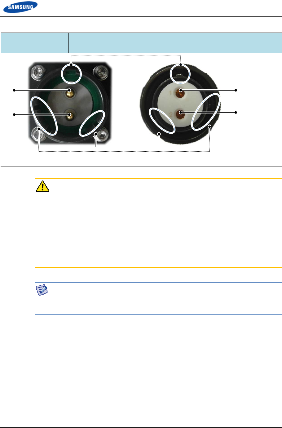
Chapter 2 Installation of RRH-B8
Smart MBS RRH-B8 Installation Manual v3.0 69
©Samsung Proprietary and Confidential
Table 14. Power Connector Pin Map
Connector Circular Connector
1: -48 V 2: RTN
Cautions for the connecting a power cable to a connector are as follows:
- Place the grooves of a cable side connector on the protrusions of a system side
connector to fit into each other and connect them by turning a coupling nut on the
top of the cable side connector. If the connectors are not aligned in a line, the
connectors can be damaged when connecting the connectors.
- Do not connect the power cable to the connector with excessive force as the
connector may be damaged.
- Do not forcefully pull the power cable or bend it beyond the allowed radius of
curvature when fixing to the connector.
To ensure stability in power supply, a circuit breaker must be installed on the
power cable connected to the rectifier (or power distributor).
Capacity of -48 VDC circuit breaker is 32 A.
[Cable side Connector:
JONHON, 003-00028953-01]
[System side Connector:
JONHON, 003-00028953-03]
1 1
2 2
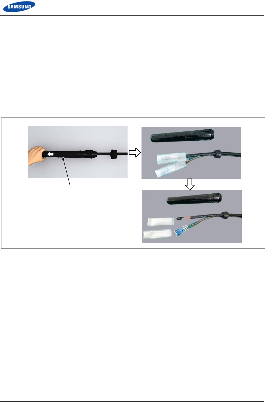
Chapter 2 Installation of RRH-B8
Smart MBS RRH-B8 Installation Manual v3.0 70
©Samsung Proprietary and Confidential
Connecting CPRI cable
Follow the steps below to connect the CPRI cable for the interface between RRH-
B8 and UADU.
Type 1_Using Hybrid Cable
1 Disassemble the water-proof cap from the Hybrid cable (blue group, white
group).
Figure 51. Connecting CPRI Cable_Type 1 (1)
Water-Proof Cap
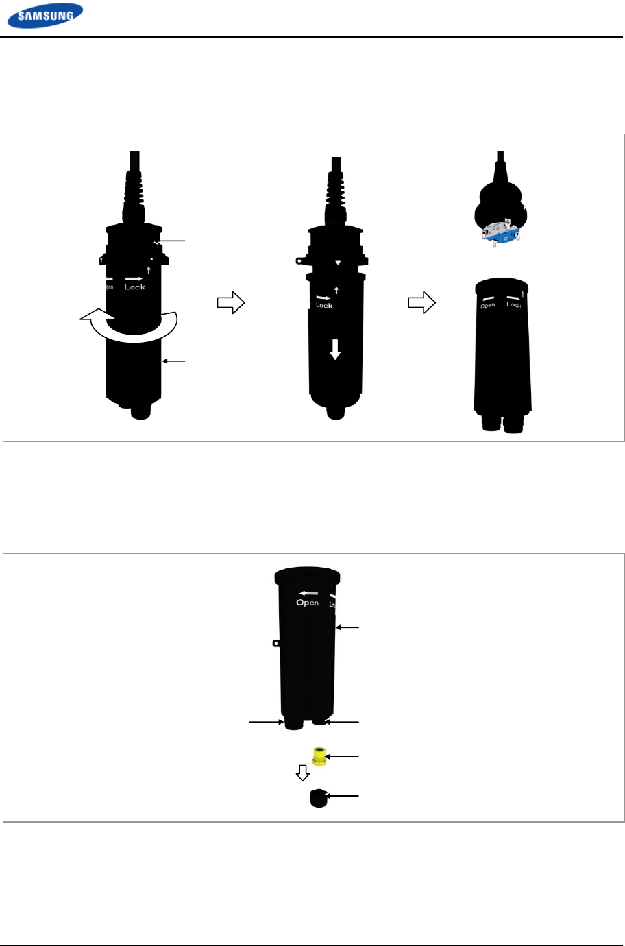
Chapter 2 Installation of RRH-B8
Smart MBS RRH-B8 Installation Manual v3.0 71
©Samsung Proprietary and Confidential
2 Disassemble the junction cylinder body and cap by pulling down the junction
cylinder cap after rotating the cap to open.
Figure 52. Connecting CPRI Cable_Type 1 (2)
3 Disassemble the cable gland nut and water-proof filler for the blue group CPRI
cable inlet at the bottom of junction cylinder cap. (Be careful not to lose the
removed cable gland nut and water-proof filler.)
Figure 53. Connecting CPRI Cable_Type 1 (3)
Water-proof Filler
Cable Gland Nut
Junction Cylinder Cap
Cable Gland (for Blue Group) Cable Gland(for White Group)
Junction Cylinder Cap
Junction Cylinder Body
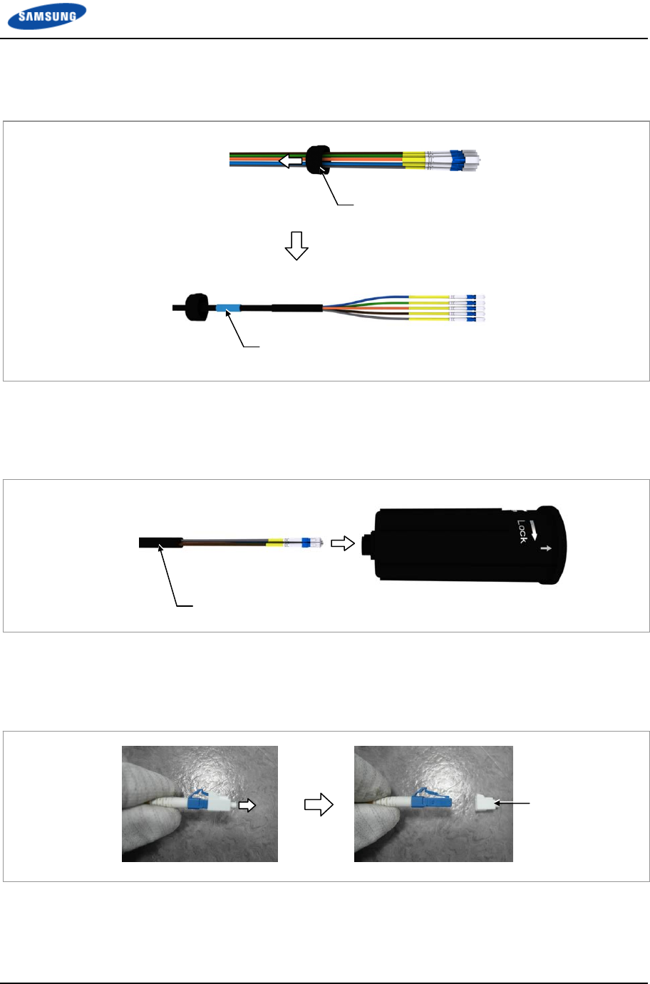
Chapter 2 Installation of RRH-B8
Smart MBS RRH-B8 Installation Manual v3.0 72
©Samsung Proprietary and Confidential
4 Insert the removed cable gland nut to the blue group CPRI cable.
Figure 54. Connecting CPRI Cable_Type 1 (4)
5 Insert the blue group CPRI cable through the cable gland hole (blue group) of
junction cylinder cap.
Figure 55. Connecting CPRI Cable_Type 1 (5)
6 Remove the dust caps from the blue, orange, and green cables among the blue
group CPRI cables.
Figure 56. Connecting CPRI Cable_Type 1 (6)
Dust Cap
CPRI Cable (Blue Group)
CPRI Cable (Blue Group)
Cable Gland Nut
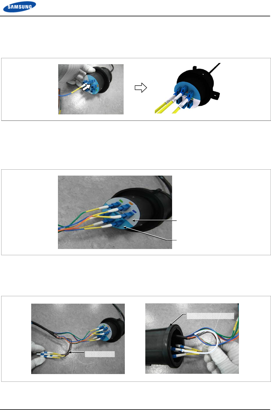
Chapter 2 Installation of RRH-B8
Smart MBS RRH-B8 Installation Manual v3.0 73
©Samsung Proprietary and Confidential
7 Connect the connectors of CPRI cables (blue, orange, green) to the blue group
optic ports (blue, orange, green) of junction cylinder body.
Figure 57. Connecting CPRI Cable_Type 1 (7)
8 After working for the white group CPRI cables as the same procedures 3)~6)
and connect the connectors to the white group optic ports (blue, orange, green)
of junction cylinder body.
Figure 58. Connecting CPRI Cable_Type 1 (8)
9 Roll and put the spare cables of blue group and white group CPRI cables
(brown, gray) inside the cylinder cap.
Figure 59. Connecting CPRI Cable_Type 1 (9)
CPRI Cable(Blue Group)
Junction Cylinder Cap
Spare Cable
Blue Group
White Group
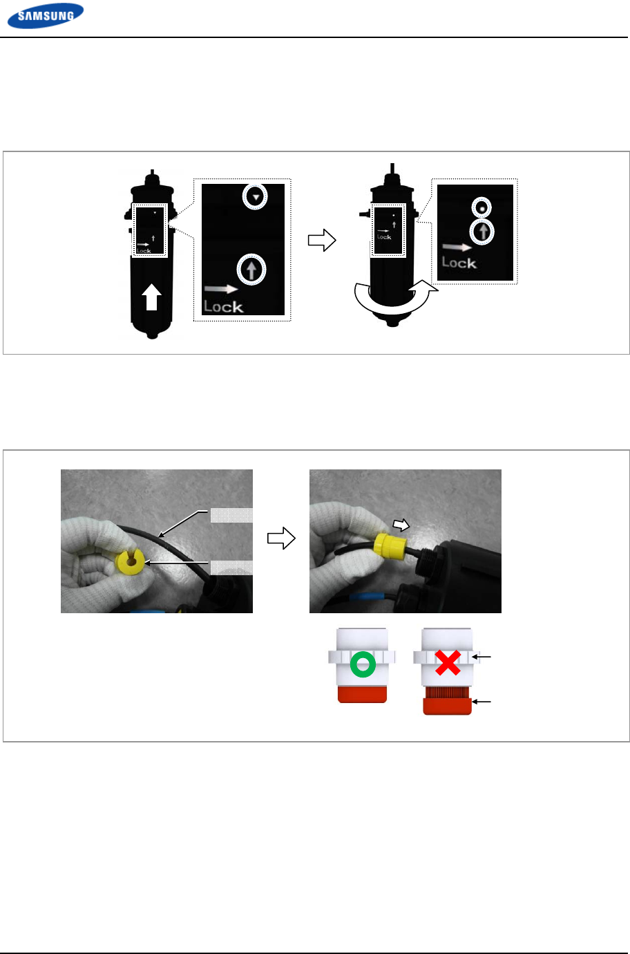
Chapter 2 Installation of RRH-B8
Smart MBS RRH-B8 Installation Manual v3.0 74
©Samsung Proprietary and Confidential
10 Insert the junction cylinder body and cap with aligning the ▽ and ↑ marks,
and rotate the cap to lock until the ○ and ↑ marks are aligned
Figure 60. Connecting CPRI Cable_Type 1 (10)
11 Insert the water-proof filler to the CPRI cable and push up the water-proof
filler to fit in the cable gland body.
Figure 61. Connecting CPRI Cable_Type 1 (11)
CPRI Cable
Water-proof Filler
Water-proof Filler
Cable Gland Body
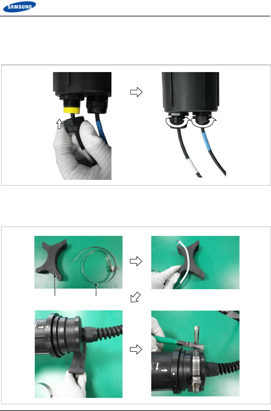
Chapter 2 Installation of RRH-B8
Smart MBS RRH-B8 Installation Manual v3.0 75
©Samsung Proprietary and Confidential
12 Fasten the cable gland nut to the cable gland body.
※ Cable gland nut torque: 4.43 lbf·ft (61.2 kgf·cm)
Figure 62. Connecting CPRI Cable_Type 1 (12)
13 Fix the mount to the junction cylinder body using a steel band and cut the
remain part using a nipper or plier.
Figure 63. Connecting CPRI Cable_Type 1 (13)
Mount Steel Band
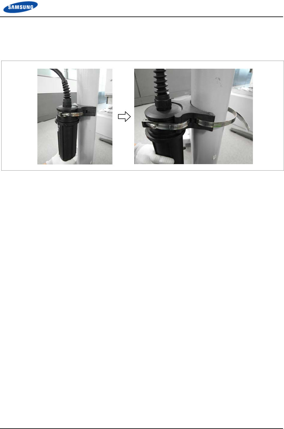
Chapter 2 Installation of RRH-B8
Smart MBS RRH-B8 Installation Manual v3.0 76
©Samsung Proprietary and Confidential
14 Place the fixed mount of junction cylinder to the pole and fix it using a steel
band.
Figure 64. Connecting CPRI Cable_Type 1 (14)
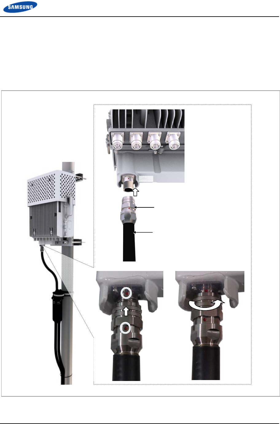
Chapter 2 Installation of RRH-B8
Smart MBS RRH-B8 Installation Manual v3.0 77
©Samsung Proprietary and Confidential
15 Install the CPRI cable, which is connected to the junction cylinder, to the
RRH-B8 MFC port.
16 Insert the CPRI connector after aligning the mark of CPRI connector and mark
of RRH-B8 MFC port connector.
17 Fasten the nut of the cable side connector.
Figure 65. Connecting CPRI Cable_Type 1 (15)
CPRI Connector (MFC)
MFC
CPRI Cable
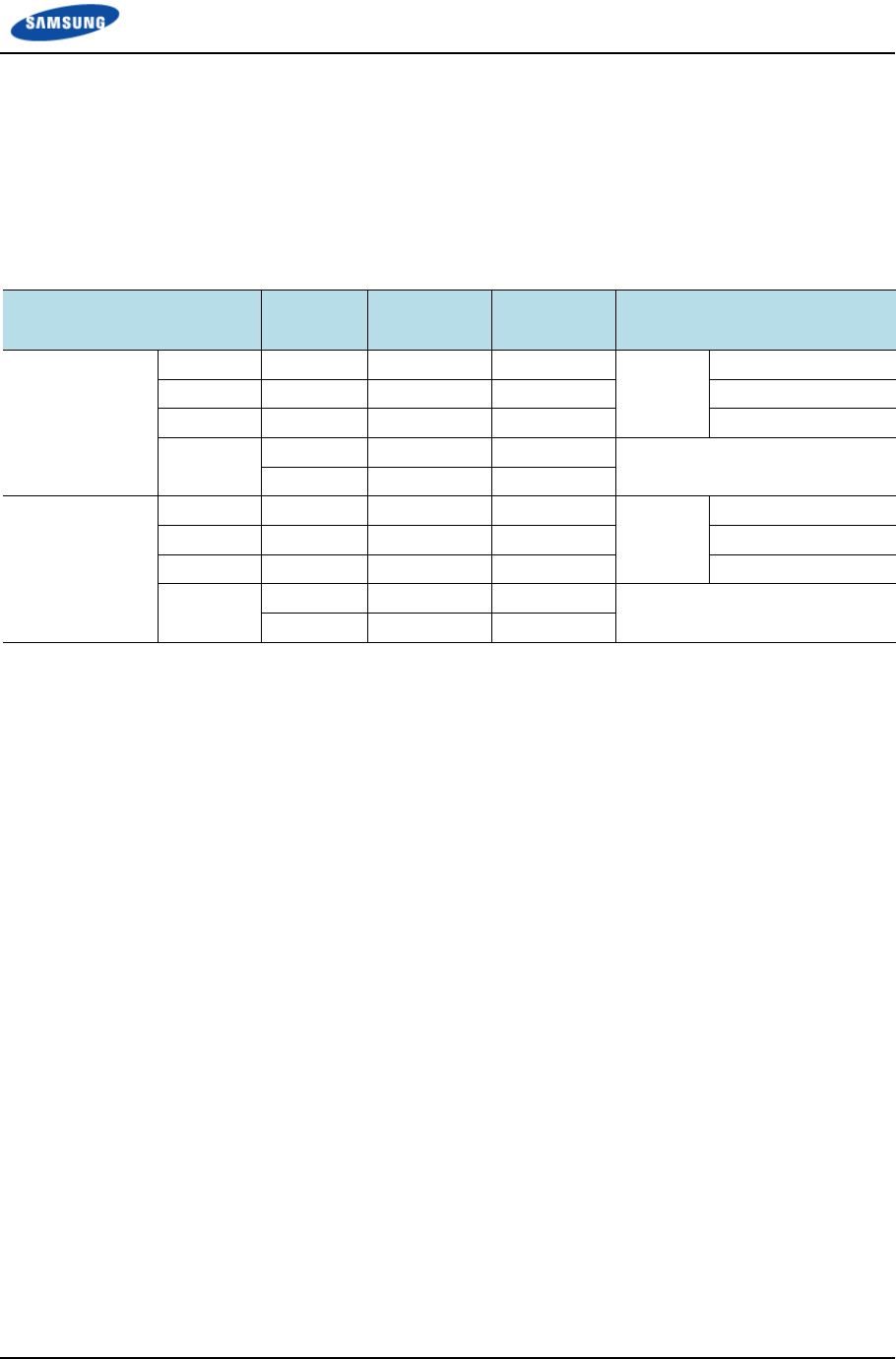
Chapter 2 Installation of RRH-B8
Smart MBS RRH-B8 Installation Manual v3.0 78
©Samsung Proprietary and Confidential
Case 1) 1Sector / RRH Configuration
1 RRH can support max.3 Carriers 1Sector at 8T8R configuration with DU#0,
max.6 carriers 1Sector 4T4R configuration with DU#0 and max.6carriers 1Sector
4T8R configuration with DU#0 and DU#1.
The CPRI cable connections are as follows.
Table 15. DU~RRH Optic Junction Cylinder Hybrid Cable Connection Configuration (1Sector / RRH)
TD-LTE UADU LCA3_L6
(α)
LCA3_L8
(β)
LCA3_L10
(γ)
RRH-B8_α/β/γ
(Junction Cylinder)
DU #1
(White Group)
LCA3 #2 Green Green Green White
Group
Port #2 (Green)
LCA3 #1 Orange Orange Orange Port #1 (Orange)
LCA3 #0 Blue Blue Blue Port #0 (Blue)
Spare
Cable
Brown Brown Brown Spare Cable
Gray Gray Gray
DU #0
(Blue Group)
LCA3 #2 Green Green Green Blue
Group
Port #2 (Green)
LCA3 #1 Orange Orange Orange Port #1 (Orange)
LCA3 #0 Blue Blue Blue Port #0 (Blue)
Spare
Cable
Brown Brown Brown Spare Cable
Gray Gray Gray
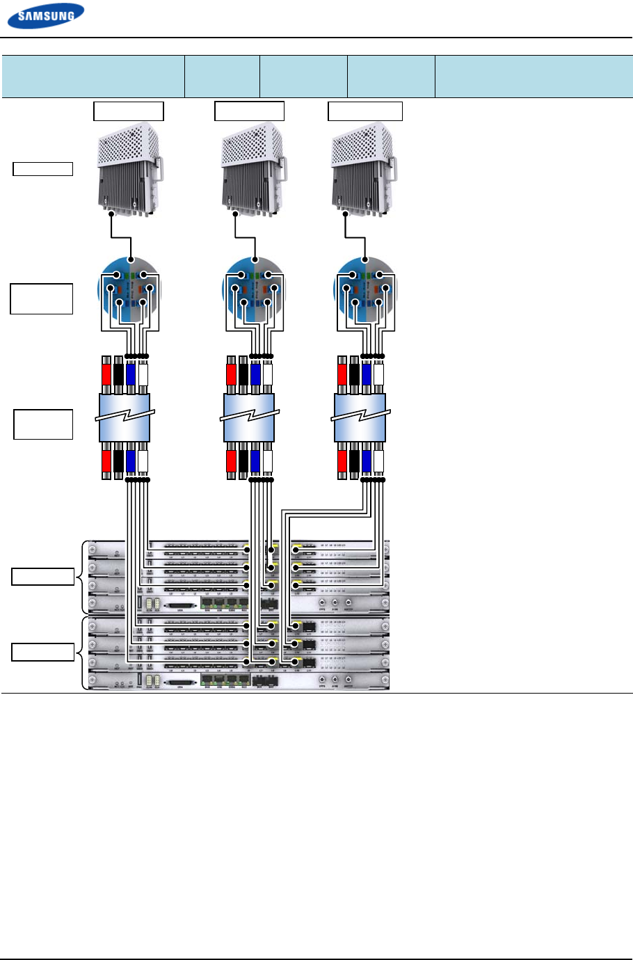
Chapter 2 Installation of RRH-B8
Smart MBS RRH-B8 Installation Manual v3.0 79
©Samsung Proprietary and Confidential
TD-LTE UADU LCA3_L6
(α)
LCA3_L8
(β)
LCA3_L10
(γ)
RRH-B8_α/β/γ
(Junction Cylinder)
UADU #1
Sector #0 (α) Sector #1 (β)Sector #2 (γ)
Junction
Cylinder
Hybrid
Cable
RRH-B8
UADU #0
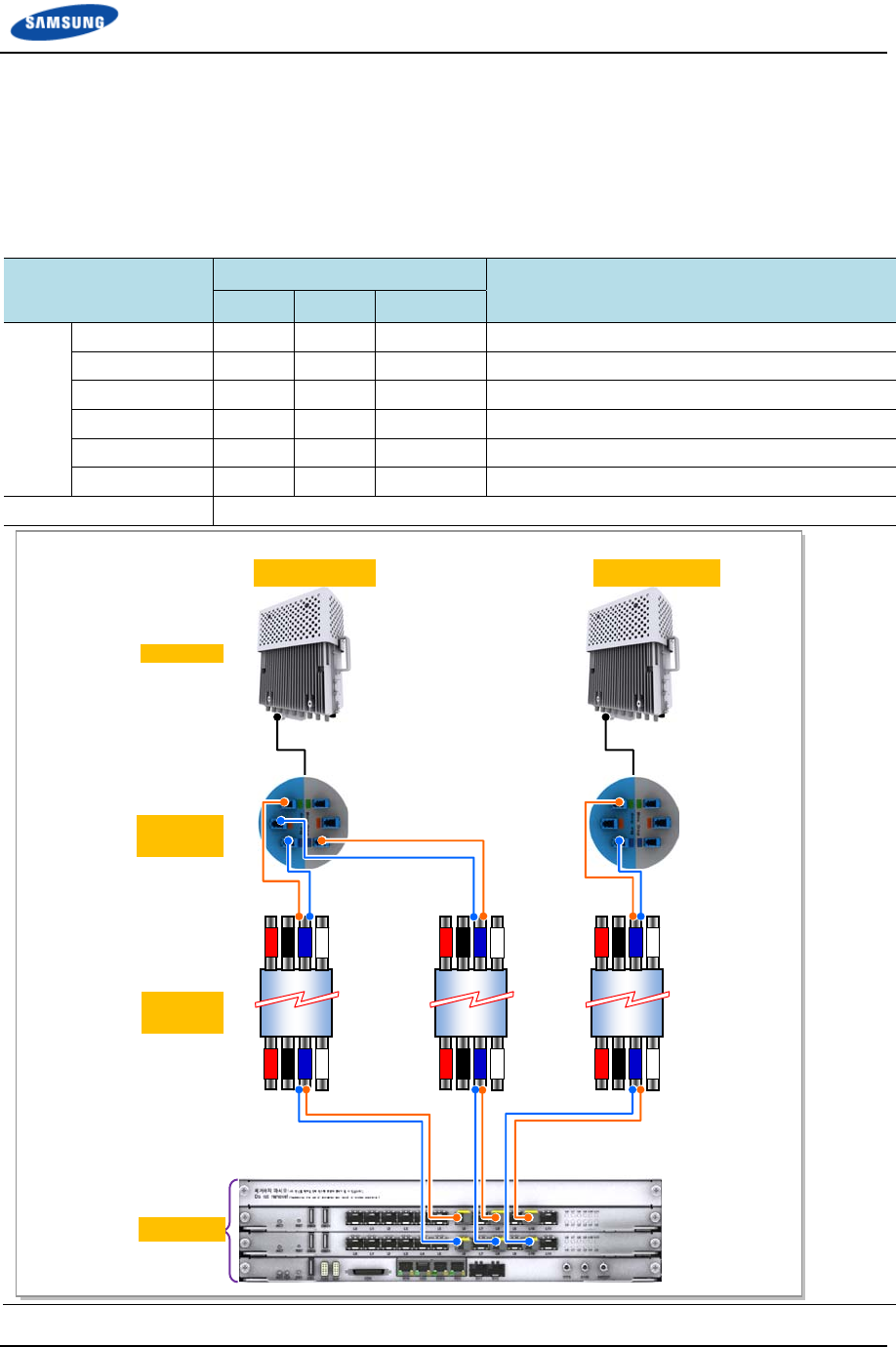
Chapter 2 Installation of RRH-B8
Smart MBS RRH-B8 Installation Manual v3.0 80
©Samsung Proprietary and Confidential
Case 2) 2Sector / RRH Configuration (4T4R 2Sector with 1 RRH)
1 RRH can support max.3 Carriers/2Sector at 4T4R configuration with DU#0.
The CPRI cable connections are as follows
Table 16. DU~RRH Optic Junction Cylinder Hybrid Cable Connection Configuration (4T4R 2Sector with 1
RRH)
TD LTE UADU Hybrid Cable(Group) RRH-B8(Junction Cylinder)
α(Blue) β(Blue) γ(Blue)
DU#0 LCA3#1_L6 Orange - - RRH#0(α/ β)_Blue Group_Port#2(Green)
LCA3#0_L6 Blue - - RRH#0(α/ β)_Blue Group_Port#0(Blue)
LCA3#1_L8 - Orange - RRH#0(α/ β)_White Group_Port#0(Blue)
LCA3#0_L8 - Blue - RRH#0(α/ β)_Blue Group_Port#1(Orange)
LCA3#1_L10 - - Orange RRH#1(γ)_Blue Group_Port#2(Green)
LCA3#0_L10 - - Blue RRH#1(γ)_Blue Group_Port#0(Blue)
Spare Cable Green, Brown, Gray
#0(Sector_α/β)#1(Sector_γ)
Junction
Cylinder
Hybrid
Cable
RRH-B8
UADU #0
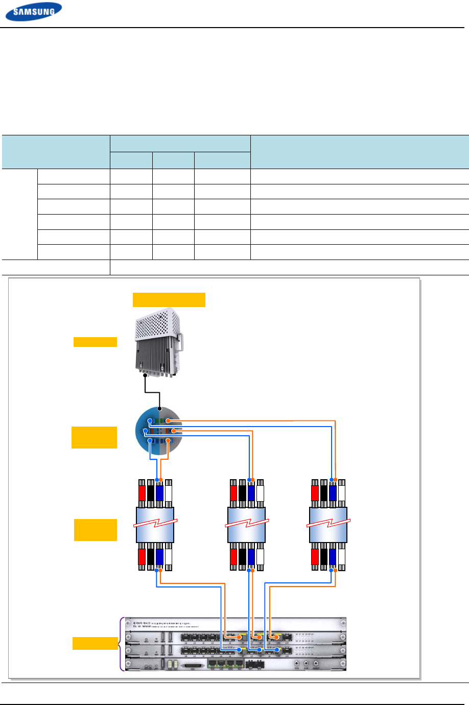
Chapter 2 Installation of RRH-B8
Smart MBS RRH-B8 Installation Manual v3.0 81
©Samsung Proprietary and Confidential
Case 3) 3Sector / RRH Configuration (2T2R 3Sector with 1 RRH)
1 RRH can support max.3 Carriers/3Sector at 2T2R configuration with DU#0.
The CPRI cable connections are as follows.
Table 17. DU~RRH Optic Junction Cylinder Hybrid Cable Connection Configuration (2T2R 3Sector with 1
RRH)
TD LTE UADU Hybrid Cable(Group) RRH-B8(Junction Cylinder)
α(Blue) β(Blue) γ(Blue)
DU#0 LCA3#1_L6 Orange - - RRH#0(α/ β/ γ)_White Group_Port#0(Blue)
LCA3#0_L6 Blue - - RRH#0(α/ β/ γ)_Blue Group_Port#0(Blue)
LCA3#1_L8 - Orange - RRH#0(α/ β/ γ)_White Group_Port#1(Orange)
LCA3#0_L8 - Blue - RRH#0(α/ β/ γ)_Blue Group_Port#1(Orange)
LCA3#1_L10 - - Orange RRH#0(α/ β/ γ)_White Group_Port#2(Green)
LCA3#0_L10 - - Blue RRH#0(α/ β/ γ)_Blue Group_Port#2(Green)
Spare Cable Green, Brown, Gray
#0(Sector_α/β/γ)
Junction
Cylinder
Hybrid
Cable
RRH-B8
UADU #0
Chapter 2 Installation of RRH-B8
Smart MBS RRH-B8 Installation Manual v3.0 82
©Samsung Proprietary and Confidential
The optical module and cable used in the system emit bright laser beams.
Always handle them with care as there is risk of serious injury if the eyes are
exposed to the laser beam of the optical cable.
The cable connection between the UADU CPRI port and RRH-B8 side optic port
of the junction cylinder varies according to the number (one or two) of TD-LTE
DU installed in the DU cabinet.
Connect the optic cable according to the connection configuration in ‘Table 13’.
Be careful not to connect the optic cable to a wrong place. If the optic cable is
connected to a wrong place, the call connection fails.
The optic cable consists of 5 cores. The grey cable is the spare cable for the
replacement in case that one of the 3-core optic cables would fail.
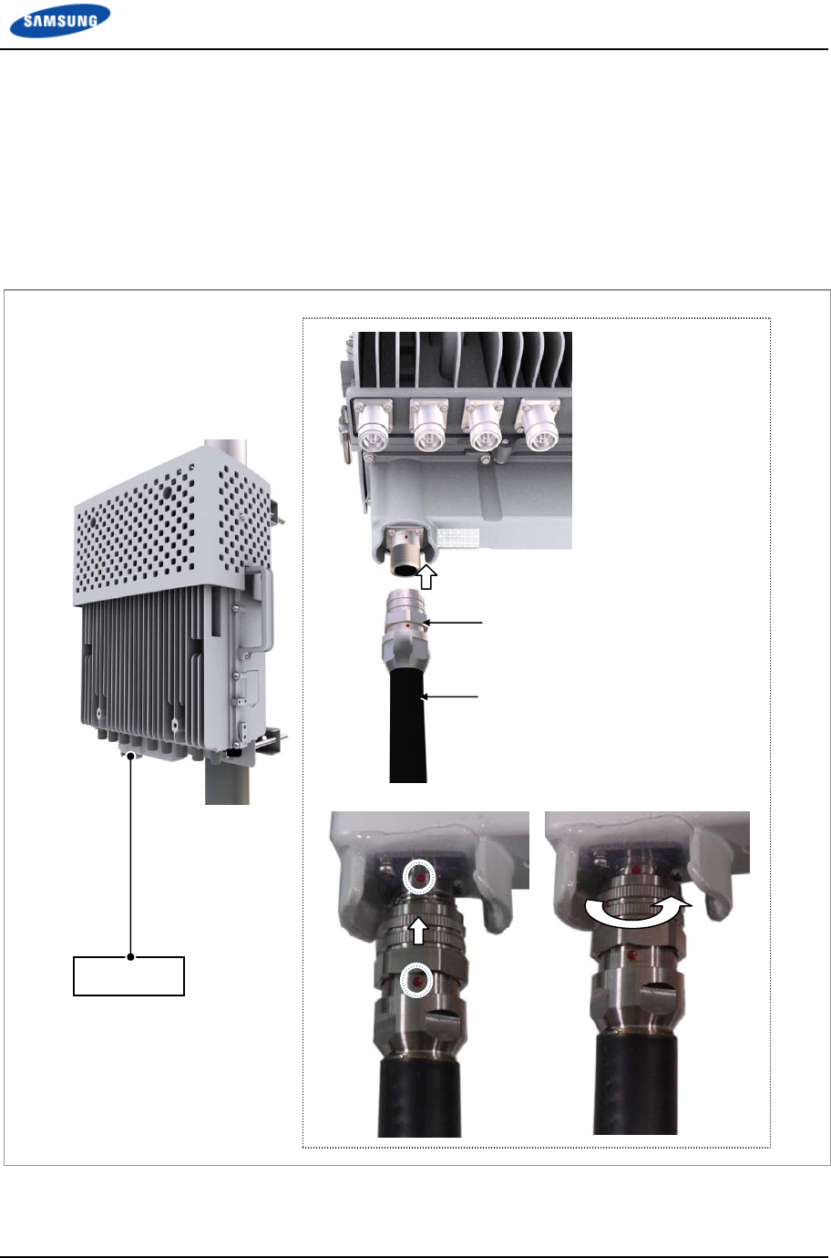
Chapter 2 Installation of RRH-B8
Smart MBS RRH-B8 Installation Manual v3.0 83
©Samsung Proprietary and Confidential
Type 2_Using AUX Hybrid Cable
1 Install the AUX hybrid from the DU to the RRH-B8.
2 Insert the CPRI connector after aligning the mark of CPRI connector and mark
of RRH-B8 MFC port connector.
3 Fasten the nut of the cable side connector.
Figure 66. Connecting CPRI Cable_Type 2
[DU]
CPRI Cable
CPRI Connector (MFC)
MFC
CPRI Cable
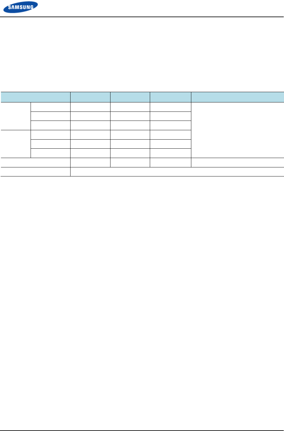
Chapter 2 Installation of RRH-B8
Smart MBS RRH-B8 Installation Manual v3.0 84
©Samsung Proprietary and Confidential
Case 1) 1Sector / RRH Configuration
1 RRH can support max.3 Carriers 1Sector at 8T8R configuration with DU#0,
max.6 carriers 1Sector 4T4R configuration with DU#0 and max.6carriers 1Sector
4T8R configuration with DU#0 and DU#1.
The CPRI cable connections are as follows.
Table 18. DU~RRH AUX Hybrid Cable Connection Configuration (1Sector / RRH)
TD-LTE UADU LCA3_L6 (α) LCA3_L8 (β) LCA3_L10 (γ) RRH-B8_ α/β/γ
DU #1 LCA3 #2 Black Black Black MFC Connector
LCA3 #1 Gray Gray Gray
LCA3 #0 Brown Brown Brown
DU #0 LCA3 #2 Green Green Green
LCA3 #1 Orange Orange Orange
LCA3 #0 Blue Blue Blue
Tube Color Orange Green Blue -
Spare Cable Tube Color: Purple
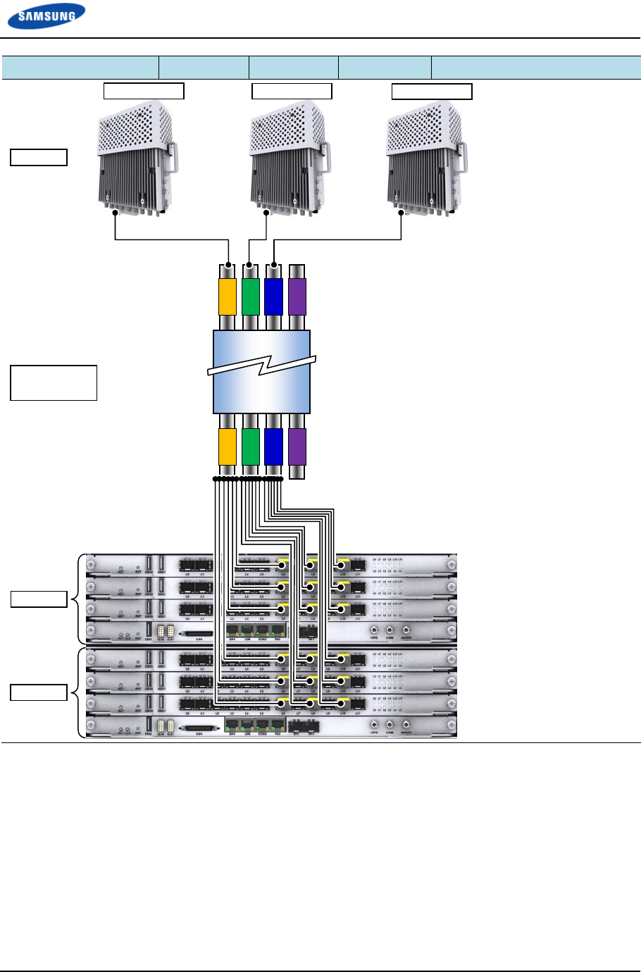
Chapter 2 Installation of RRH-B8
Smart MBS RRH-B8 Installation Manual v3.0 85
©Samsung Proprietary and Confidential
TD-LTE UADU LCA3_L6 (α) LCA3_L8 (β) LCA3_L10 (γ) RRH-B8_ α/β/γ
UADU #1
UADU #0
Sector #0 (α) Sector #1 (β)Sector #2 (γ)
AUX
Hybrid Cable
RRH-B8
Chapter 2 Installation of RRH-B8
Smart MBS RRH-B8 Installation Manual v3.0 86
©Samsung Proprietary and Confidential
Case 2) 2Sector / RRH Configuration (4T4R 2Sector with 1 RRH)
1 RRH can support max.3 Carriers/2Sector at 4T4R configuration with DU#0.
The CPRI cable connections are as follows.
Table 19. DU~RRH AUX Hybrid Cable Connection Configuration (4T4R 2Sector with 1 RRH)
TD LTE UADU AUX Hybrid Cable Tube Color(Sector) RRH-B8
Orange(α) Orange(β) Green(γ)
DU#0 LCA3#1_L6 Orange - - RRH#0(α/ β), MFC Connector
LCA3#0_L6 Blue - -
LCA3#1_L8 - Brown -
LCA3#0_L8 - Green -
LCA3#1_L10 - - Orange RRH#1(γ), MFC Connector
LCA3#0_L10 - - Blue
Spare Cable Gray
Black
Green
Brown
Gray
Black
-
Tube Color : Blue, Purple
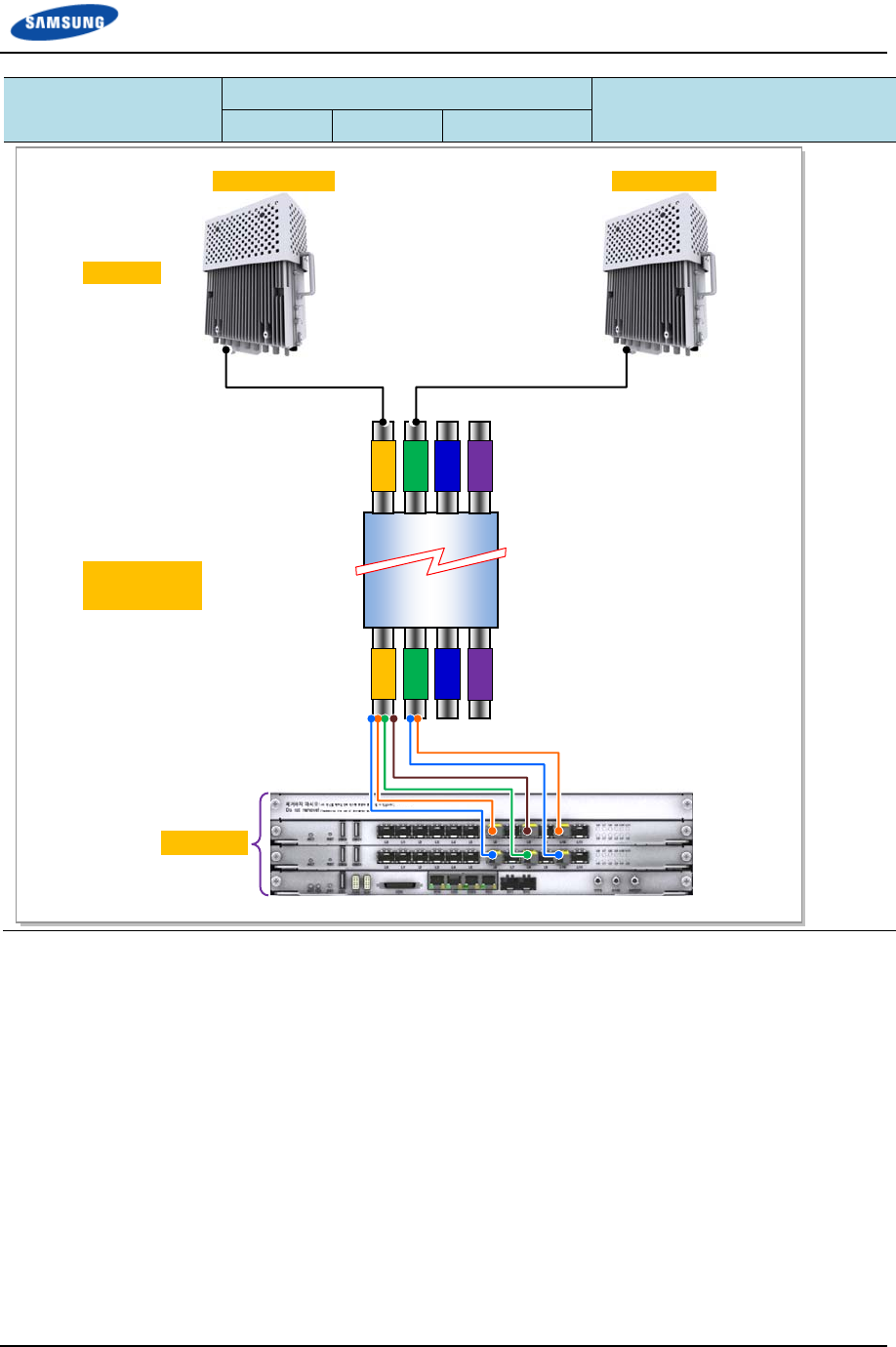
Chapter 2 Installation of RRH-B8
Smart MBS RRH-B8 Installation Manual v3.0 87
©Samsung Proprietary and Confidential
TD LTE UADU AUX Hybrid Cable Tube Color(Sector) RRH-B8
Orange(α) Orange(β) Green(γ)
Sector #0(α
/
β) Sector #1(γ)
AUX
Hybrid Cable
RRH-B8
UADU #0
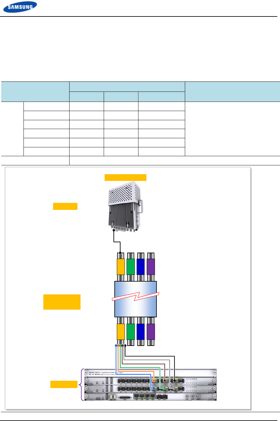
Chapter 2 Installation of RRH-B8
Smart MBS RRH-B8 Installation Manual v3.0 88
©Samsung Proprietary and Confidential
Case 3) 3Sector / RRH Configuration (2T2R 3Sector with 1 RRH)
1 RRH can support max.3 Carriers/3Sector at 2T2R configuration with DU#0.
The CPRI cable connections are as follows.
Table 20. DU~RRH AUX Hybrid Cable Connection Configuration (2T2R 3Sector with 1 RRH)
TD LTE UADU AUX Hybrid Cable Tube Color(Sector) RRH-B8
Orange(α) Orange(β) Green(γ)
DU#0 LCA3#1_L6 Orange - - RRH#0(α/ β/ γ), MFC Connector
LCA3#0_L6 Blue - -
LCA3#1_L8 - Brown -
LCA3#0_L8 - Green -
LCA3#1_L10 - - Black
LCA3#0_L10 - - Gray
Spare Cable Tube Color : Green, Blue, Purple
Sector #0(α
/
β/ γ)
AUX
Hybrid Cable
RRH-B8
UADU #0
Chapter 2 Installation of RRH-B8
Smart MBS RRH-B8 Installation Manual v3.0 89
©Samsung Proprietary and Confidential
The optical module and cable used in the system emit bright laser beams.
Always handle them with care as there is a risk of serious injury if the eyes are
exposed to the laser beam of the optical cable.
The cable connection between the UADU CPRI port and RRH-B8 varies
according to the number (one or two) of TD-LTE DU installed in the DU cabinet.
Connect the optic cable according to the connection configuration in ‘Table 14’.
Be careful not to connect the optic cable to a wrong place. If the optic cable is
connected to a wrong place, the call connection fails.
The AUX hybrid cable consists of 4 cable groups (orange/green/blue/purple). The
purple cable is the spare cable for the replacement in case that one of the optic
cables would fail.

Chapter 2 Installation of RRH-B8
Smart MBS RRH-B8 Installation Manual v3.0 90
©Samsung Proprietary and Confidential
Installation Test
If the installation of the system is complete, progress the installation test to check
the status of the system.
Table 21. Construction Status Checklist
Category Check Items Criteria Result Remarks
Pass Fail
System
Installation
System fixing status
(Vertical and horizontal)
Horizontal and vertical locations
System arrangement status Horizontal and vertical locations
Locking status and standard
compatibility of
bolts/nuts/washers
Visual inspection and magnet test
External wiring and other
wirings
Visual inspection for twist, array
and arrangement
System cable installation
status
Checking twist, distortion and
installation status
External connector
connection
Visual inspection to check poor
contact (Tightening status)
Other appurtenant work
(Cable duct installation and
others)
Visual inspection
Power
Acceptance
Equipment’s power cable
specification
Visual inspection
Rectifier ↔ System Visual inspection
Cabling Status Visual inspection for twisted or
entangled status
Damage of cable sheath Visual inspection
System power connector Visual inspection to check
whether the power connector is
connected normally without
separation.
Inspection for the power
connector shaking status
System input voltage (BATT
voltage)
Measurement by digital meter
(voltmeter)
External
interface
Optic Cabling Status Visual inspection
Ground
Construction
Ground line standard Visual inspection
Ground bar ↔ System Visual inspection
Ground line cabling status Cabling status check
Termination treatment of
the ground line (Pressure
Terminal)
Visual inspection
Feeder Line
status
Feeder Line installation and
fixing status
View, consistency, bending
ANT installation and Visual inspection (ANT stick
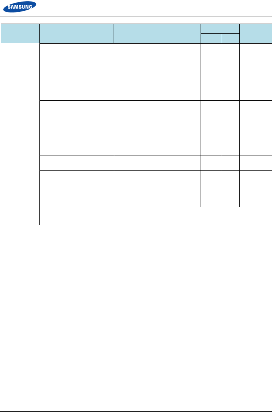
Chapter 2 Installation of RRH-B8
Smart MBS RRH-B8 Installation Manual v3.0 91
©Samsung Proprietary and Confidential
Category Check Items Criteria Result Remarks
Pass Fail
connection status shaking status)
Connection and end
processing status
View, consistency
Various TAG
Status
Feeder Line tag Visual inspection (Content:
Length, LOSS value, position)
Power cable tag Visual inspection
Ground table tag Visual inspection
Attachment status of the
label for the real-name
construction system
Indoor: wall side of the
gate side
Outdoor: inside of the
cover of the distribution
box
Visual inspection (size, material,
etc.)
Cable duct, bolt connection
status
Visual inspection
Feeder line Entrance end
processing status (Outdoor)
Visual inspection (Checking back
side Connection)
Status of inside/outside of
the system and vicinity of
the base station
Visual inspection
General
Opinion

Smart MBS RRH-B8 Installation Manual v3.0 92
©Samsung Proprietary and Confidential
Appendix A Acronyms
AISG Antenna Interface Standards Group
CAL Calibration
CPRI Common Public Radio Interface
DC Direct Current
DU Digital Unit
EMI Electro Magnetic Interference
GPS Global Positioning Satellite
LCA3 LTE Channel Card Type 3
LTE Long Term Evolution
MBS Multi-modal Base Station
MGB Main Ground Bar
MFC Multi Fiber Connector
RET Remote Electrical Tilting
RF Radio Frequency
RRH Remote Radio Head
TD Time Division
TDD Time Division Duplex
TGB Tower Ground Bar
UADU Universal Platform Digital Unit
VSWR Voltage Standing Wave Ratio

Smart MBS RRH-B8 Installation Manual v3.0 93
©Samsung Proprietary and Confidential
Appendix B Sector Antenna
Installation
Cautions when Installing a Sector Antenna
Precautions of antenna installation are as follows.
Sector antennas should be installed vertically. (± 1)
Antenna is the precise material, so be careful not to make damage or form
change.
When moving antenna, use the tool suitable to rating. In addition, use the rated
carrying device which is at least 200 % or more than antenna considering the
stability.
Be careful not to give too much strength to the antenna.
If it rains, suspend connecting the feeder cable and antenna.
Fix it after adjusting the direction of antenna exactly.
Distance between steel tower and antenna and the distance between send-
receive antennas are based on the antenna layout.
Attach the antenna on the position specified in the drawing.
Install the antenna not to make a feature change of the antenna considering the
direction of the radiation
When connect the connector to the antenna, not making the alien substance
flowed and is not under the influence of PIMD.
Measure VSWR of all antennas and the value should be within the regulated
value.

Appendix B Sector Antenna Installation
Smart MBS RRH-B8 Installation Manual v3.0 94
©Samsung Proprietary and Confidential
Sector Antenna Installation
The method of sector antenna installation is as follows.
1 Put up an antenna pole and insert the sector antenna into the antenna pole
using a fixing clamp.
2 Set the antenna’s up/down tilt to 0° and fix the fixing clamps at the top and
bottom.
3 After tightening the fixing clamp, adjust the antenna up/down (tilt) depending
on the signal strength. The bolt of the guide clamp must be loosened, so the
antenna angle can be adjusted.
4 After setting the antenna angle, fasten the bolt of the guide clamp, which was
loosened previously. Regarding the nut, the double nut mounting should be
used to prevent the nut from coming loose.
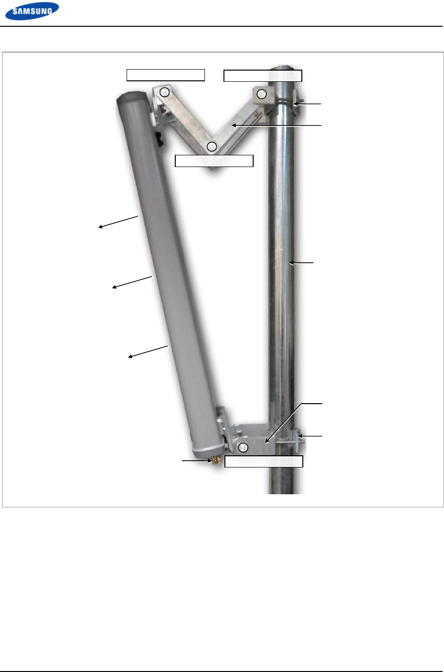
Appendix B Sector Antenna Installation
Smart MBS RRH-B8 Installation Manual v3.0 95
©Samsung Proprietary and Confidential
Figure 67. Sector Antenna
Antenna Input Port
Pole
Main Radiation
Direction
Upper Fixing Clamp
Lower Fixing Clamp
Upper Guide Clamp
Lower Guide Clamp
Guide Clamp Bolt_2
Guide Clamp Bolt_1
Guide Clamp Bolt_3
Guide Clamp Bolt_4
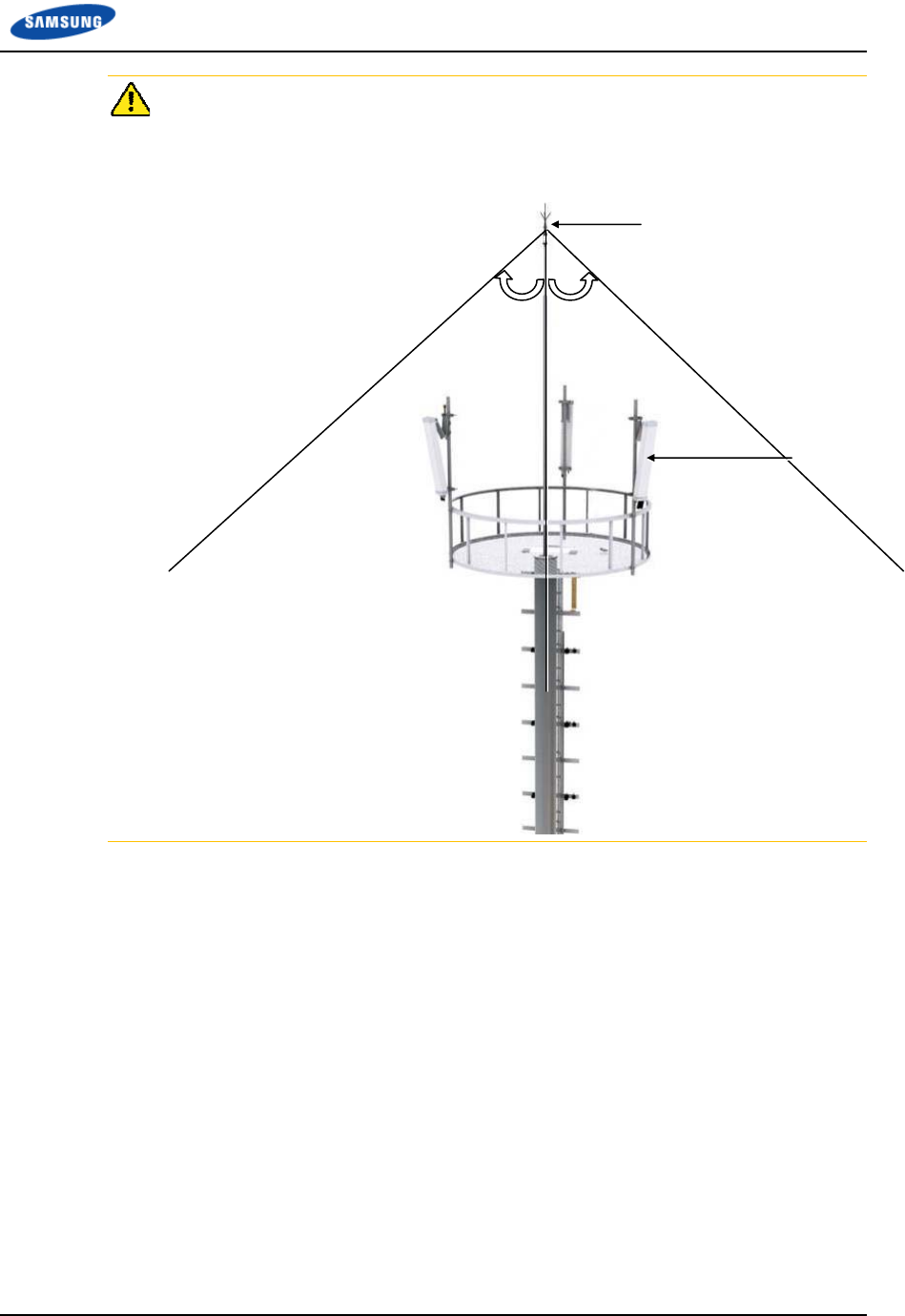
Appendix B Sector Antenna Installation
Smart MBS RRH-B8 Installation Manual v3.0 96
©Samsung Proprietary and Confidential
When you install the antenna, the antenna must be within the protective angle
(left/right side 45° each from the central axis) to prevent the antenna from
lightning damage.
Lightning Rod
45°45°
RF Antenna
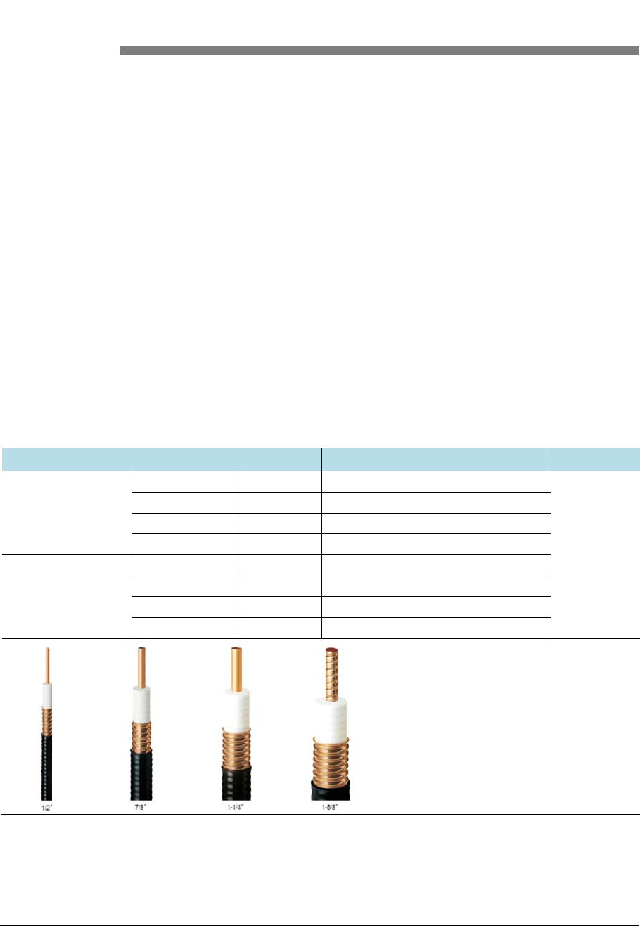
Smart M
B
©Samsu
n
Wh
e
Table 2
2
Specifi
c
LS Fee
d
RFS F
e
B
S RRH-B8 I
n
n
g Proprietar
y
A
e
n ins
t
W
2
. Curvature
R
c
ation
d
er Line
e
eder Line
n
stallation Ma
y
and Confide
n
A
pp
e
t
allin
g
W
hen install
i
Put a pla
t
If there i
s
wiring.
After co
n
the contr
a
Attach t
h
easy to r
e
When co
n
cable, co
n
The curv
a
radius.
R
adius of Fe
e
HFC-12D
HFC-22D
HFC-33D
HFC-42D
LCF12-50
LCF78-50
LCFS114-
5
LCF158-50
n
ual v3.0
n
tial
e
ndix
g
the f
e
i
ng the feed
e
t
e to work n
o
s
external da
m
n
necting the
a
a
cted pipe u
s
h
e cognitive
t
e
cognize.
n
necting ca
b
n
nect strong
l
a
ture radius
e
der Cable fo
1/2 in
7/8 in
1-1/4
1-5/8
1/2 in
7/8 in
5
0 1-1/4
1-5/8
C F
e
e
eder
,
e
r, the follo
w
o
t to make d
a
m
age of the
a
ntenna to t
h
s
ing the con
t
t
apes to the
b
b
inet, antenn
a
l
y to preven
t
should be
m
o
r Outdoor
A
llo
w
n
. 4.02
n
. 9.84
in. 14.9
6
in. 20.0
8
n
. 4.92
n
. 9.84
in. 14.9
6
in. 19.6
9
e
ed
e
,
the
c
w
ing caution
s
a
mage for t
h
feeder cable
h
e feeder ca
b
t
racted tube.
b
oth ends of
a
and lighte
n
t
from gener
a
aximized, k
e
w
ed Radius o
f
in. (125 mm)
in. (250 mm)
6
in. (380 mm
8
in. (510 mm
in. (125 mm)
in. (250 mm)
6
in. (380 mm
9
in. (500 mm
e
r Lin
c
autio
n
s
shall be co
n
e surface of
, cut the da
m
b
le, finish th
e
the feeder c
a
n
ing arrestor
,
a
ting reflect
e
e
ep the mini
m
Curvature
)
)
)
)
e W
o
n
s
n
sidered:
the feeder c
a
m
aged part a
n
e
connectio
n
a
ble, which
m
,
etc. to the
f
e
d wave.
m
um curvat
u
Re
m
Out
d
97
o
rk
a
ble.
n
d work
part of
m
akes it
f
eeder
u
re
m
ark
d
oor
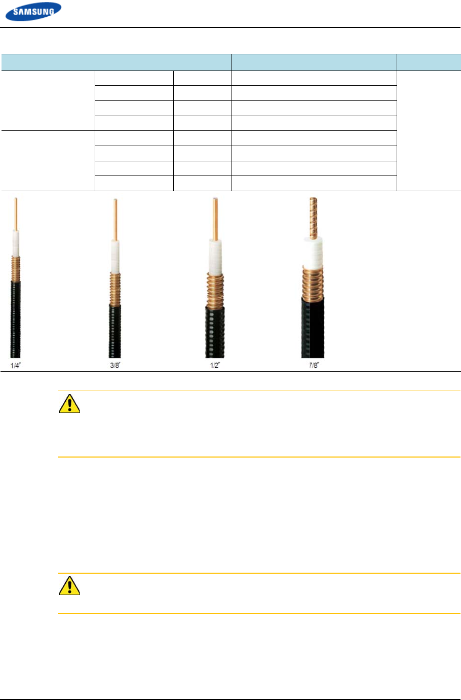
Smart M
B
©Samsu
n
Table 2
3
Specifi
c
LS Fee
d
RFS F
e
B
S RRH-B8 I
n
n
g Proprietar
y
3
. Curvature
R
c
ation
d
er Line
e
eder Line
W
b
c
i
t
C
w
n
stallation Ma
y
and Confide
n
R
adius of Fe
e
HFSC 6D
HFSC 10D
HFSC 12D
HFSC 22D
SCF14-50
SCF38-50
SCF12-50
UCF78-50
W
hen install
i
b
ent should
b
c
urvature for
t
may affect
Ensure t
h
the areas
Connect
t
not appl
y
Wind th
e
of rubbe
r
electricit
y
C
onnecting t
h
w
ho finished
n
ual v3.0
n
tial
e
der Cable fo
1/4 in
3/8 in
1/2 in
7/8 in
1/4 in
3/8 in
1/2 in
7/8 in
i
ng a feeder
l
b
e larger tha
n
the feeder l
i
the perform
a
h
at the feede
r
chiefly use
d
t
he connect
o
y
excessive f
o
e
self-
b
ondin
g
r
tape) to the
y
to the 2 ti
m
h
e feeder ca
b
the related
e
o
r Indoor
A
llo
w
n
. 0.98
n
. 0.98
n
. 1.26
n
. 4.92
n
. 0.98
n
. 0.98
n
. 1.26
n
. 4.92
l
ine, the rad
i
n
the allowe
d
i
ne installati
o
a
nce of the s
r
cable does
d
by people.
o
r to the ante
o
rce.
g rubber tap
e
connector c
o
m
es or more
a
b
le connecto
e
ducation sh
o
w
ed Radius o
f
in. (25 mm)
in. (25 mm)
in. (32 mm)
in. (125 mm)
in. (25 mm)
in. (25 mm)
in. (32 mm)
in. (125 mm)
i
us of curvat
u
d
radius of c
u
o
n is less th
a
y
stem.
not interfer
e
nna in a stra
i
e
overlappin
o
nnection p
a
a
nd then co
v
r is critical
p
o
uld perfor
m
Append
Curvature
u
re of the se
c
u
rvature. If t
h
a
n the allow
e
with steel t
o
i
ght line an
d
g
(keep a di
s
a
rt and wind
v
er with the
h
p
rocess, so t
h
m
.
d
ix C Feeder
L
Re
m
Ind
o
c
tions wher
e
h
e radius of
e
d radius of
c
o
wers, ladde
d
after conne
c
s
tance as the
the vinyl ta
p
h
eat shrink t
u
h
e qualified
w
L
ine Work
98
m
ark
o
or
e
cables
c
urvature,
r
s and in
c
ting, do
half size
p
e for
u
be.
w
orkers

Appendix C Feeder Line Work
Smart MBS RRH-B8 Installation Manual v3.0 99
©Samsung Proprietary and Confidential
Table 24. Connector Connection Torque Value
Connector Torque Value
SMA connector 0.18 lbf·ft (2.5 kgf·cm)
TNC connector 0.65 lbf·ft (9 kgf·cm)
N-type connector 1.45 lbf·ft (20 kgf·cm)
Din-type connector 14.46 lbf·ft (200 kgf·cm)
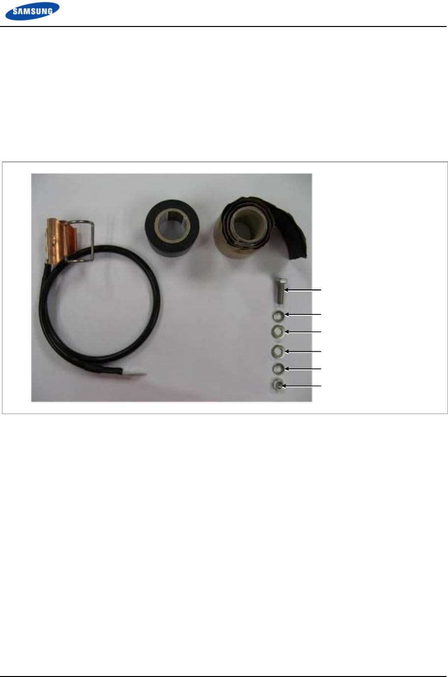
Appendix C Feeder Line Work
Smart MBS RRH-B8 Installation Manual v3.0 100
©Samsung Proprietary and Confidential
Antenna Feeder Cable Ground
Ground the antenna feeder line using the grounding kit located under the Tower
Ground Bar (TGB) installed in the lower section of the tower or in the antenna
feeder line duct.
The way to connect the ground kit of feeder is as follows:
Figure 68. Feeder Cable Grounding (1)
M6 Hex. Nut
Ground Kit
Insulation Tape
Rubber Tape
M6 × 25L Hex. Bolt
M6 Spring Washer
M6 Plain Washer
M6 Plain Washer
M6 Spring Washer
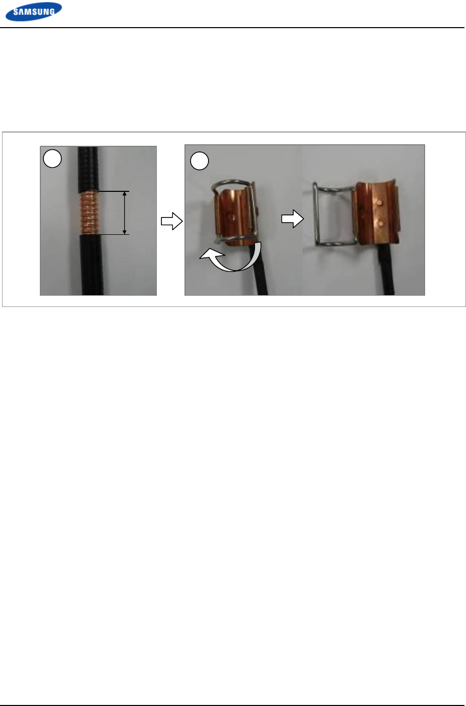
Appendix C Feeder Line Work
Smart MBS RRH-B8 Installation Manual v3.0 101
©Samsung Proprietary and Confidential
1 Remove about 55 mm of the sheath of cable when the 2.17 in. (55 mm). feeder
cable is used.
2 Open it by returning hook of the clamp fixing for Ground kit in the left
direction.
Figure 69. Feeder Cable Grounding (2)
3 Insert the ground kit clamp into the place from which the feeder line sheath is
removed.
4 Pull the clamp lock to the upward so that the lock can be hung on the global
protrusion area on the side.
5 Overlap the exposed part of the ground kit clamp using rubber tape (Keep a
distance as the half size of rubber tape) and press it with your hands lightly to
make rubber tape adhere well.
6 Wrap the part where the rubber tape is attached using insulation tape two times
or more. When cutting off the tape, cut it off neatly using a cutting device such
as scissors or a knife.
2.17 in.
(55 mm)
1 2
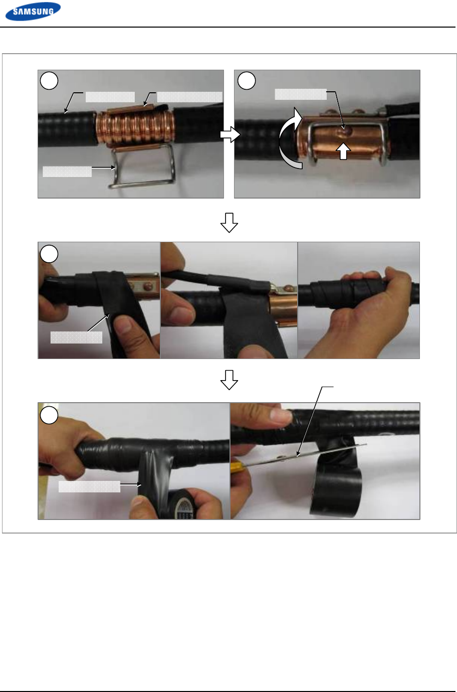
Appendix C Feeder Line Work
Smart MBS RRH-B8 Installation Manual v3.0 102
©Samsung Proprietary and Confidential
Figure 70. Feeder Cable Grounding (3)
Protrusion
Clamp Lock
Feeder Line Ground Kit Clamp
Scissors (knife)
Rubber Tape
Insulation Tape
3 4
5
6
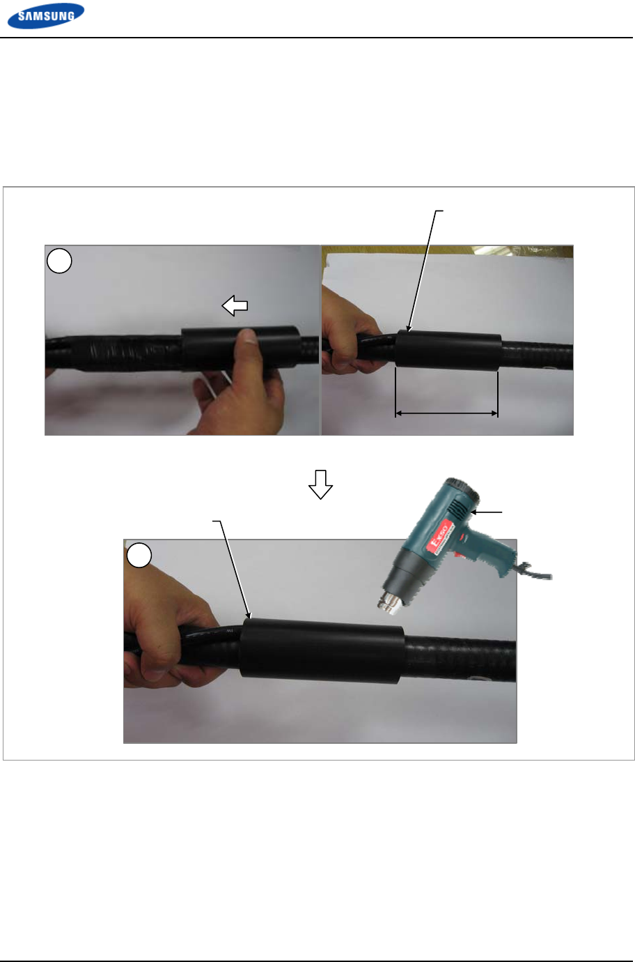
Appendix C Feeder Line Work
Smart MBS RRH-B8 Installation Manual v3.0 103
©Samsung Proprietary and Confidential
7 Align the heat shrink tube, inserted when installing the feeder line, into the
fixing part of the ground kit.
o Heat shrink tube: Φ 1.65 in., 7.87 in (Φ 42 mm, 200 mm)
8 Shrink the heat shrink tube [jelly type, 7.87 in. (200 mm)] by heating gun.
Figure 71. Feeder Cable Grounding (4)
7.87 in.
(200 mm)
Heating Gun
Heat Shrink Tube
Heat Shrink Tube
7
8
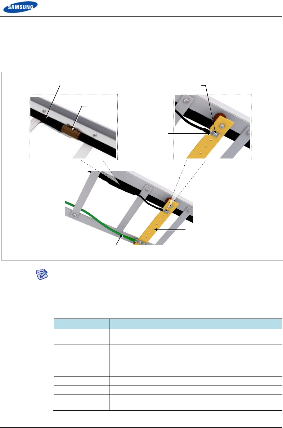
Appendix C Feeder Line Work
Smart MBS RRH-B8 Installation Manual v3.0 104
©Samsung Proprietary and Confidential
9 After the ground kit has been installed to the feeder line, attach the pressure
terminal (1 hole) of the ground cable connected to the ground kit to the TGB.
10 When attaching the pressure terminal, use M6 × 25L hex. Bolts.
Figure 72. Feeder Cable Grounding (5)
The specifications, clamp, and pressure terminal type of the ground kit and TGB
differ depending on manufacturers. Make sure to check the specifications of the
ground kit and TGB, and identify the installation method before installing it.
Table 25. TGB Installation Example
Category Description
TGB Usage Earth terminal board for feeder cable for grounding in using the
feeder cable of more than 7/8 in.
TGB Location Lower section of cable rack in feeder cable duck
less than 65.62 ft (20 m): 1 (Ex. steel tower lower section)
more than 65.62 ft (20 m): 2 (Ex. steel tower lower and upper
section)
Material Pure copper
Installation Method Using the insulator to separate from the steel tower electrically
Connection Method Extract the AWG2, GV 25 mm2 ground cable to the direction of the
floor and weld it to the tower’s ground cable.
TGB (Tower Ground Bar)
TGB Ground Cable
(AWG2, GV 25 mm2 × 1C)
M6 × 25L Hex. Bolt (STS304)
Ground kit
7/8 in. Feeder Line
Pressure Terminal
(1 Hole)

Appendix C Feeder Line Work
Smart MBS RRH-B8 Installation Manual v3.0 105
©Samsung Proprietary and Confidential
Tower Ground Construction
1 Install a Tower Ground Bar (TGB) that will be used to ground a feeder cable
onto the tower.
If the height of the tower is more than 65.62 ft (20 m), two or more TGBs
should be installed (onto the lower and upper sections of the tower). If the
tower is 65.62 ft
(20 m) or less, one TGB should be installed. Since the TGB installation
location and the number of TGBs to be installed can differ depending on the
system environment and provider’s standards, consult your service provider.
2 Each TGB should be grounded and separated from other grounds. If there is an
existing ground bar or ground cable for TGB, install the TGB by branching
from it using a ground cable (AWG2, GV 25 mm2 × 1C) ground cable.
3 Fasten the Ground Kit (feeder cable grounding assembly) to the TGB ground
terminal and the tower hole using the pressure terminal hole attached at the
end of the ground kit’s ground cable.
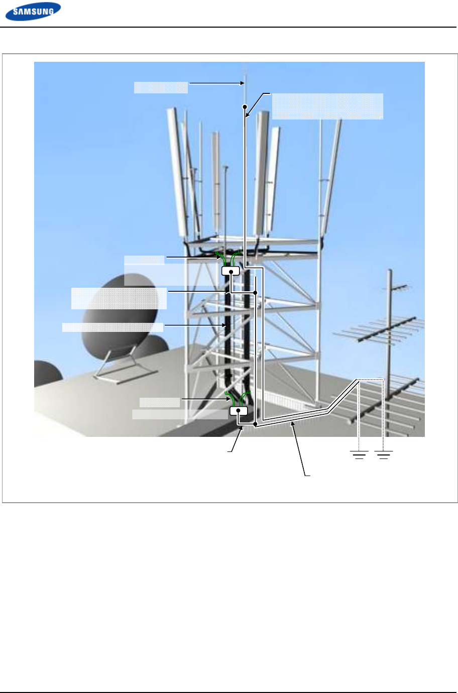
Appendix C Feeder Line Work
Smart MBS RRH-B8 Installation Manual v3.0 106
©Samsung Proprietary and Confidential
Figure 73. Connecting the Tower Ground Cable
Lightning Rod
7/8 in. Feeder Line or more
Ground Kit
TGB (Tower Ground Bar)
(Tower Height > 20 m)
TGB Ground Cable
(AWG2, GV 25 mm2 × 1C)
Lightning Rod Ground Cable
(AWG4/0, GV 95 mm2 × 1C)
TGB (Tower Ground Bar)
Ground Kit
TGB Ground Cable
(AWG2, GV 25 mm2 × 1C)
TGB Ground Cable
(AWG4/0, GV 95 mm2 × 1C)
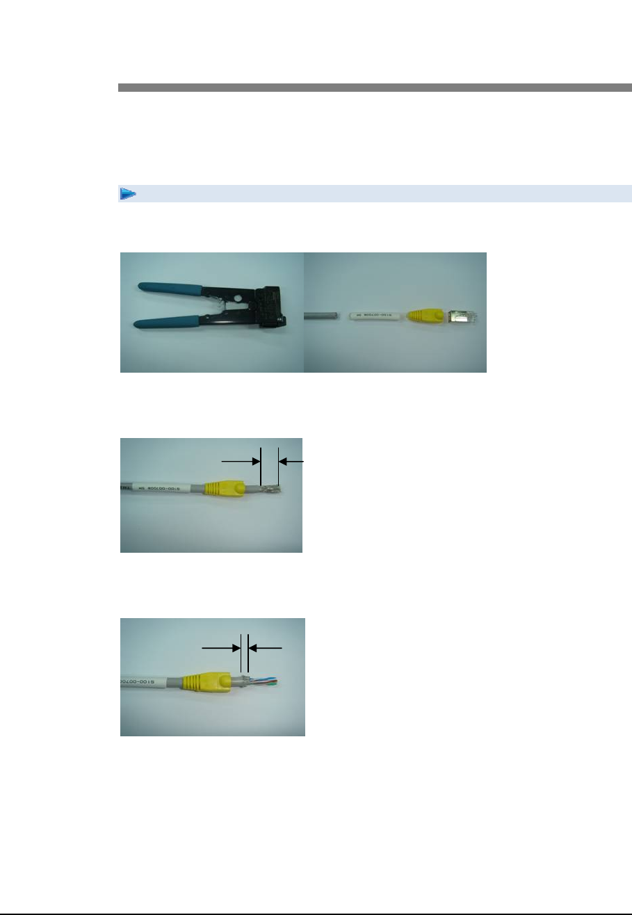
Smart MBS RRH-B8 Installation Manual v3.0 107
©Samsung Proprietary and Confidential
Appendix D Assembling
connector
RJ-45 (Shield type)
To assemble the RJ-45 connector (Shield Type):
1 Prepare work tools and materials: clamper, marking tube, connector cap, and
RJ-45 modular plug.
2 Fit the marking tube and connector cap on the RJ-45 cable.
3 Remove the cable sheath 0.67 in. (17 mm) from the end of the cable.
4 Push the aluminum shield backward.
5 Cut the shield leaving 0.2 in. (5 mm).
5 mm
17 mm
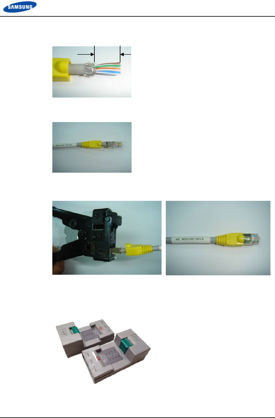
Appendix D Assembling connector
Smart MBS RRH-B8 Installation Manual v3.0 108
©Samsung Proprietary and Confidential
6 Arrange the inner cables in reference to the pin map.
7 Cut the inner cables to 0.47 in. (12 mm) long.
8 Insert the inner cables completely into the RJ-45 modular plug. Make sure that
the shield does not get in the RJ-45 modular plug.
9 Compress the plug using the clamper.
10 Push the connector cap to the connector.
11 Make sure proper assembly using the LAN tester after completion of the
connector assembly.
(The pin-map and checking the assembly may vary depending on the cable
usage.)
Ex) LAN Tester
12 mm
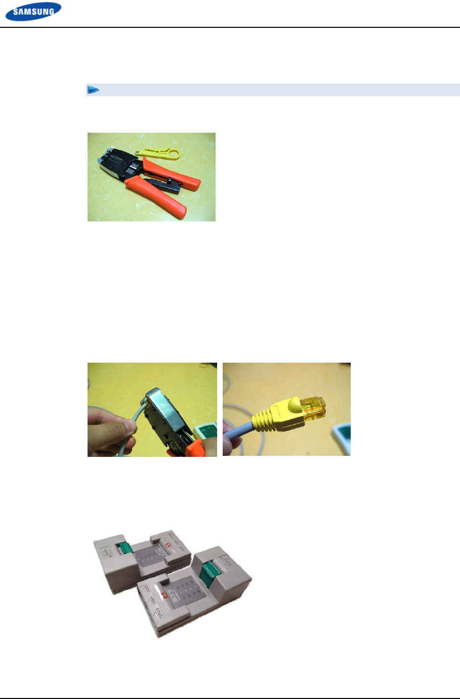
Appendix D Assembling connector
Smart MBS RRH-B8 Installation Manual v3.0 109
©Samsung Proprietary and Confidential
RJ-45 (Normal type)
To assemble the RJ-45 connector (Normal Type):
1 Prepare work tools and materials: clamper, connector cap, and RJ-45 modular
plug.
2 Fit the connector cap on the RJ-45 cable.
3 Remove the cable sheath 0.67 in. (17 mm) from the end of the cable.
4 Arrange the inner cables in reference to the pin map.
5 Cut the inner cables to 0.47 in. (12 mm) long.
6 Insert the inner cables completely into the RJ-45 modular plug.
7 Compress the plug using the clamper.
8 Push the connector cap to the connector.
9 Make sure proper assembly using the LAN tester after completion of the
connector assembly.
(The pin-map and checking the assembly may vary depending on the cable
usage.)
Ex) LAN Tester
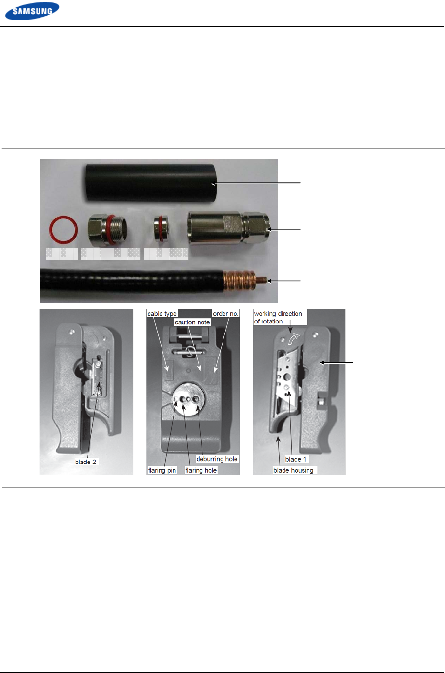
Appendix D Assembling connector
Smart MBS RRH-B8 Installation Manual v3.0 110
©Samsung Proprietary and Confidential
N type-male (1/2 in. feeder line)
Below is the method for assembling the N-type-male connector to the 1/2 in.
feeder line.
1 The components of the N type-male are an N type-male body, an insert ring, a
clamp nut, O-ring, and a heat shrink tube, and it is assembled using the wire
stripper, trimming tool, spanner, etc.
Trimming Tool
Heat Shrink Tube
[1.1 in. (28 mm)]
Insert Ring
N type-Male Body
Clamping Nut
1/2 in. Feeder Line
O-Ring
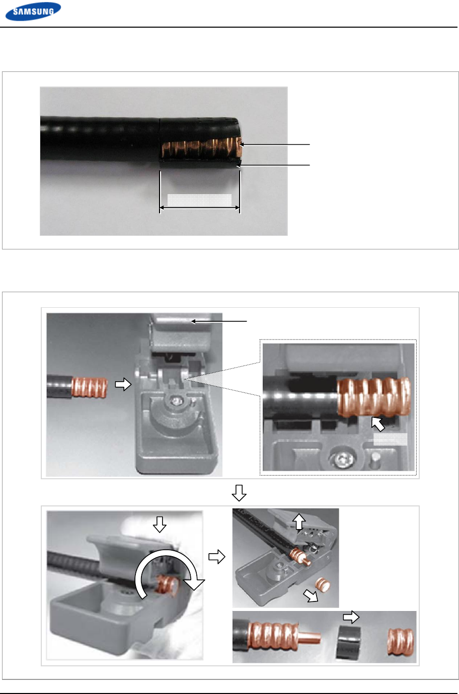
Appendix D Assembling connector
Smart MBS RRH-B8 Installation Manual v3.0 111
©Samsung Proprietary and Confidential
2 Using a stripping tool or a knife, strip the 1/2 in. feeder line by 1 in. (25.4 mm)
from the end, as shown in the figure below.
3 Remove the end 0.43 in. (11 mm) of the external conductor using a trimming
tool.
Trimming Tool
Collet
1 in. (25.4 mm)
1/2 in. Feeder Line Conductor
1/2 in. Feeder Line Jacket
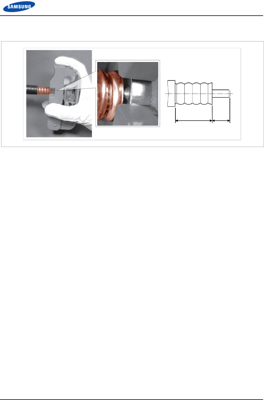
Appendix D Assembling connector
Smart MBS RRH-B8 Installation Manual v3.0 112
©Samsung Proprietary and Confidential
4 Insert the internal conductor into the deburring hole at the bottom of the
trimming tool to trim it.
5 Insert the o-ring, clamping nut, insert ring and N type-male body to the
stripped 1/2 in. feeder line in this order.
6 Tighten the clamping nut and N type-male body inserted into the 1/2 in. feeder
line firmly using a spanner.
The recommended torque for tightening the clamping nut and N type-male
body is 306~510 lbf·ft
(30~50 N.m). (Note that it should only be fastened by rotating the clamping
nut with the external body in a fixed and stable position.)
0.94 in.
(24 mm)
0.43 in.
(11 mm)
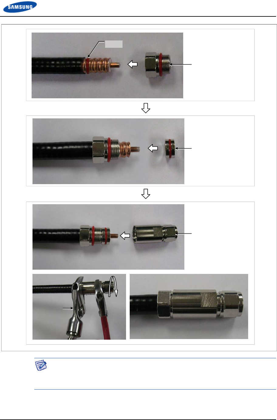
Appendix D Assembling connector
Smart MBS RRH-B8 Installation Manual v3.0 113
©Samsung Proprietary and Confidential
The shape, tool and assembly method may differ depending on the connector type
and manufacturer. Make sure to check the user manual provided by the
manufacturer before assembling.
Insert Ring
N type-Male Body
Clamping Nut
O-Ring
Maintainging
fixing status
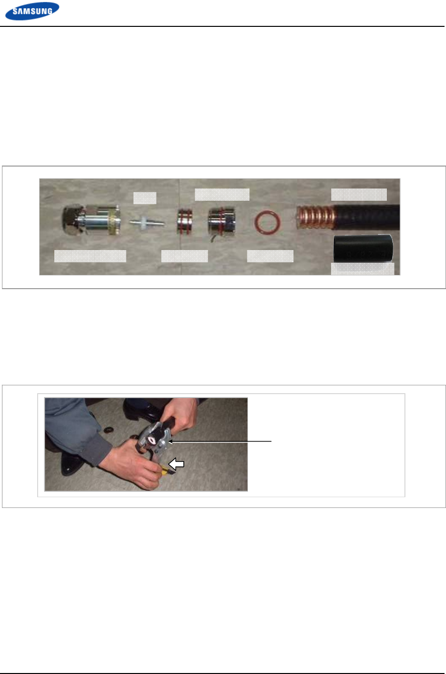
Appendix D Assembling connector
Smart MBS RRH-B8 Installation Manual v3.0 114
©Samsung Proprietary and Confidential
Din type-male (1/2 in. Feeder Line)
Below is the method for assembling the Din type-male connector to the 1/2 in.
feeder line.
1 The components of the Din type-male are an Din type-male body, a pin , an
insert ring, a clamp nut,
o-ring and a heat shrink tube, and it is assembled using the wire stripper,
trimming tool, wrench, etc.
2 Straighten the cable, then, using a suitable tool, strip it to the connector’s wire
strip length.
When cutting the sheath, hold the cable firmly with one hand and cut the cable
pulling the cutting tool inwards with the other hand. Gently rotate the tool
several times (do not pull it too hard), so that the internal copper line is not
damaged.
Cutting Tool
Din type-male Body
Pin
Insert Ring
Clamping Nut
O-Ring
Feeder Line
Heat Shrink Tube
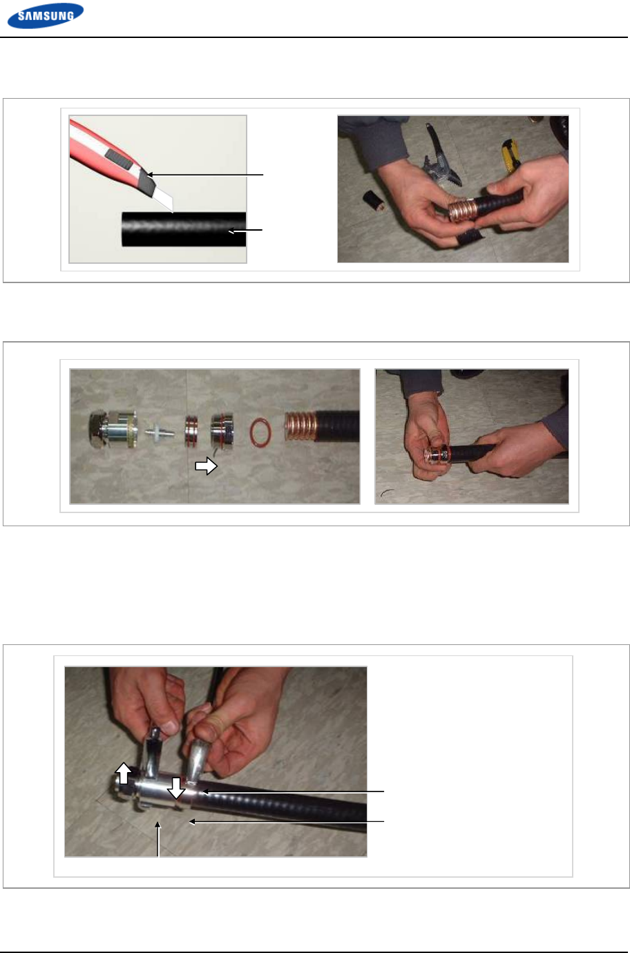
Appendix D Assembling connector
Smart MBS RRH-B8 Installation Manual v3.0 115
©Samsung Proprietary and Confidential
3 Using a cutter, cut the sheath from the stripped edge to the end of the cable and
completely strip the sheath.
4 Insert the O-ring, clamping nut, insert ring, pin and Din type-male body into
the stripped feeder line in this order.
5 Tighten firmly the clamping nut and Din type-male body inserted to the 1/2 in.
feeder line using a wrench.
The recommended torque for tightening the clamping nut and Din type-male
body is 306~510 lbf·ft (30~50 N.m). (Note that it should only be fastened by
rotating the clamping nut with the external body in a fixed and stable position.)
Spanner (Maintaining fixing status)
Clamping Nut
Din type-Male Body
Cutter
Feeder Line

Appendix D Assembling connector
Smart MBS RRH-B8 Installation Manual v3.0 116
©Samsung Proprietary and Confidential
The shape, tool and assembly method may differ depending on the connector type
and manufacturer. Make sure to check the user manual provided by the
manufacturer before assembling.

Appendix D Assembling connector
Smart MBS RRH-B8 Installation Manual v3.0 117
©Samsung Proprietary and Confidential
Finishing connector connection with a tape
Finishing the connection between connectors with the tape (Insulation tape, rubber
tape) at outdoor environment is as follows:
1 Overlap the exposed part of the connector connection part using rubber tape
(Keep a distance as the half size of rubber tape) and press it with your hands
lightly to make rubber tape adhere well.
2 Wrap the part where the rubber tape is attached using insulation tape two times
or more. When cutting off the tape, cut it off neatly using a cutting device such
as scissors or a knife.
3 Bind the end part of the insulation tape using cable tie to prevent slips.
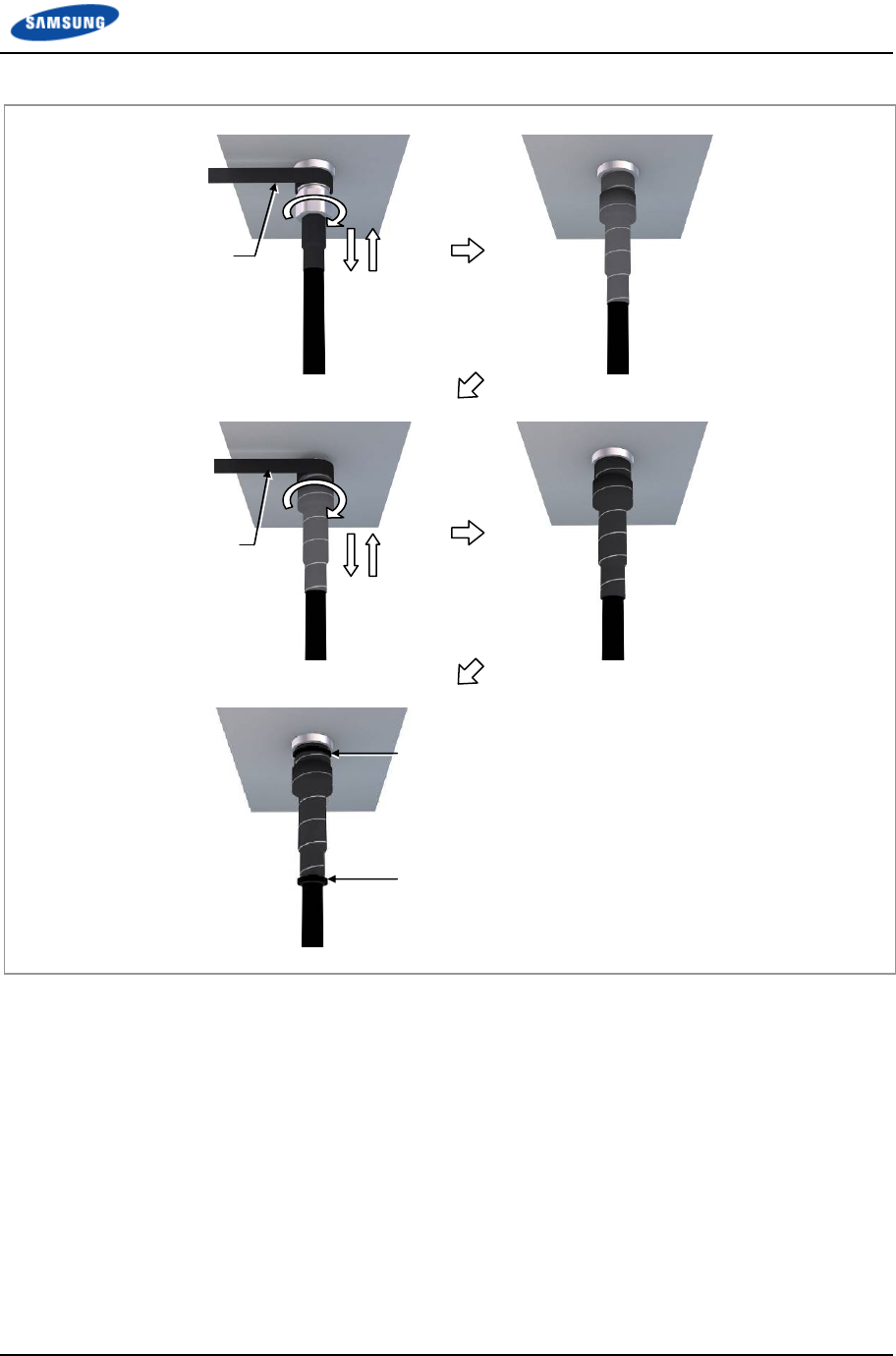
Appendix D Assembling connector
Smart MBS RRH-B8 Installation Manual v3.0 118
©Samsung Proprietary and Confidential
Figure 74. Finishing connector connection with the tape
Cable Tie
Rubber Tape
Insulation Tape
Cable Tie
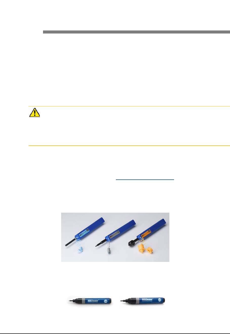
Smart MBS RRH-B8 Installation Manual v3.0 119
©Samsung Proprietary and Confidential
Appendix E Cleaning Optic
Connector
Cleaning Optic Connector
When connecting optical cable to the system, performance of system can be
decreased or fails can occur if core section of optical connector is dirty due to dust
or foreign material. Therefore, worker should clean the optic connector before
connecting optic cable to the system to prevent this phenomenon. This manual
describes the method that cleans optic connector when using the IBCTM Brand
cleaner.
Check whether there is dust or foreign material on the cutting section of the
connector core before connecting the optic cable, and keep this away from dust or
foreign material. If the cable is soiled with foreign material, do not blow to remove
them. Make sure to clean the connector in accordance with the cleaning directions
below.
When using optic connector cleaner, use the products shown in the example below
or their equivalents.
Ex) Manufacturer-USCONEC (http://www.usconec.com)
IBCTM Brand Cleaner (P/N: 9393): For LC-LC and MU Connector Cleaning
IBCTM Brand Cleaner (P/N: 9392): For SC Connector Cleaning
IBCTM Brand Cleaner (P/N: 12910): For ODC Connector Cleaning
Manufacturer-TheFibers (www.thefibers.com)
HuxCleaner 1.25 mm Type: For LC and MU Connector Cleaning
HuxCleaner 2.5 mm Type: For SC, FC and ST Connector Cleaning
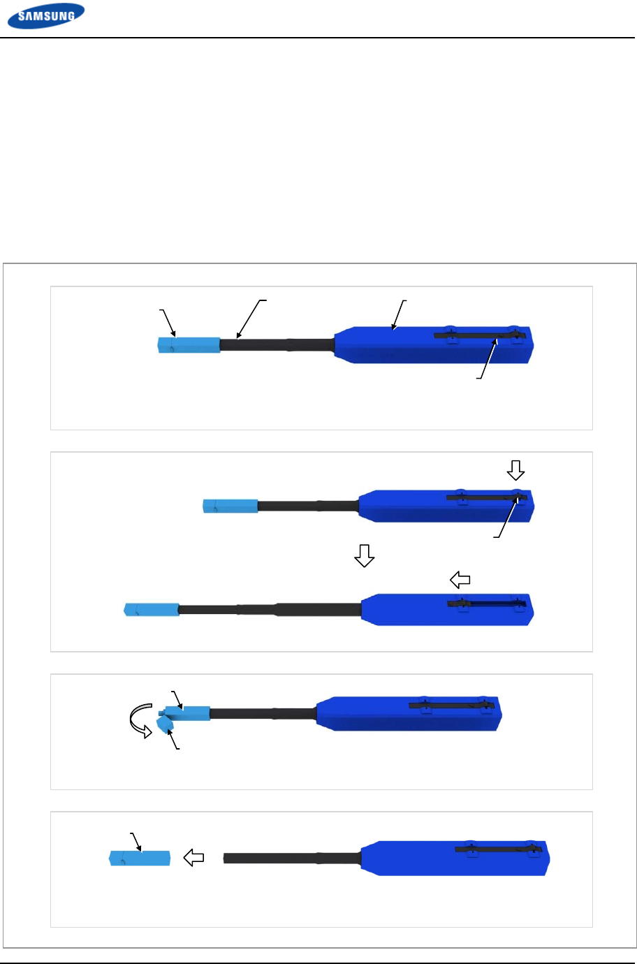
Appendix E Cleaning Optic Connector
Smart MBS RRH-B8 Installation Manual v3.0 120
©Samsung Proprietary and Confidential
IBCTM Brand Cleaner
Method that uses IBCTM Brand Cleaner is as follows:
IBCTM brand type cleaner (P/N 9393)
Method that uses IBCTM Brand Cleaner (P/N 9393) for LC-LC and MU connector
is as follows:
Figure 75. Optic Connector Cleaner (IBCTM Brand Type Cleaner: P/N 9393)
Outer Shell
[Optic Connector Cleaner Configuration]
Nozzle
Guide Cap
Lock Button
(for Extend Nozzle)
[Nozzle Extension]
[In Case of LC type Connector (Plug)]
Guide Cap
Guide Cap Cover
[In Case of LC type Connector (Jack)]
Guide Cap
Lock Button
(for Extend Nozzle)

Appendix E Cleaning Optic Connector
Smart MBS RRH-B8 Installation Manual v3.0 121
©Samsung Proprietary and Confidential
Optic Module Cleaning (LC type Jack)
1 To clean the optic module, remove the guide cap from the cleaner (P/N: 9393).
Figure 76. Optic Module Cleaning (LC type Jack) (1)
Guide Cap Outer Shell
Nozzle
[IBC Brand Cleaner: P/N 9393]
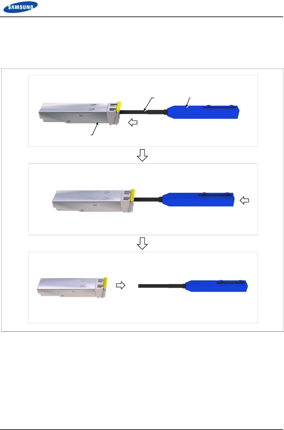
Appendix E Cleaning Optic Connector
Smart MBS RRH-B8 Installation Manual v3.0 122
©Samsung Proprietary and Confidential
2 Insert a cleaner guide cap to every core of the optic module. Clean it by
pushing the outer shell toward the nozzle until you hear the sound of the
detergent being sprayed. (Repeat once or twice.)
Figure 77. Optic Module Cleaning (LC type Jack) (2)
Nozzle Outer Shell
Optic Module
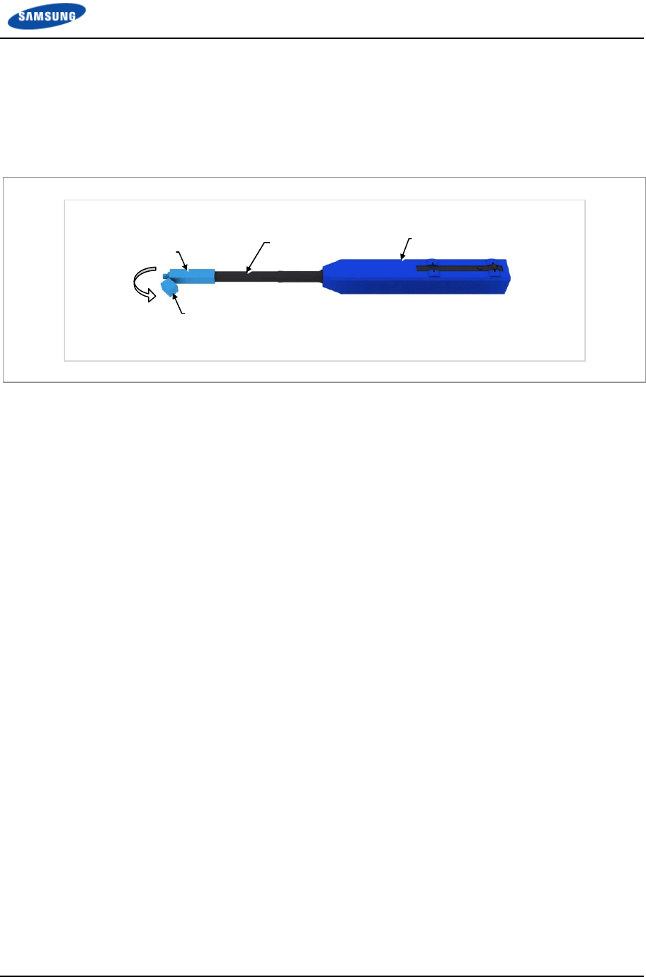
Appendix E Cleaning Optic Connector
Smart MBS RRH-B8 Installation Manual v3.0 123
©Samsung Proprietary and Confidential
Optic Cable Connector Cleaning (LC type plug)
1 To clean the optic cable connector, open the guide cap cover from the cleaner
(P/N: 9393).
Figure 78. Optic Cable Connector Cleaning (LC type plug) (1)
Guide Cap
Guide Cap Cover
Outer Shell
Nozzle
[IBC Brand Cleaner: P/N 9393]
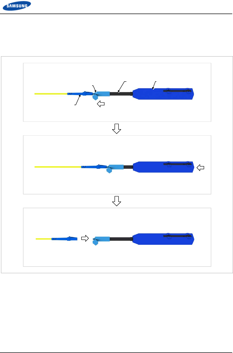
Appendix E Cleaning Optic Connector
Smart MBS RRH-B8 Installation Manual v3.0 124
©Samsung Proprietary and Confidential
2 Insert a cleaner guide cap to every core of the optic cable connector. Clean it
by pushing the outer shell toward the nozzle until you hear the sound of the
detergent being sprayed. (Repeat once or twice.)
Figure 79. Optic Cable Connector Cleaning (LC type plug) (2)
Guide Cap
Nozzle Outer Shell
LC Type Connecto
r

Appendix E Cleaning Optic Connector
Smart MBS RRH-B8 Installation Manual v3.0 125
©Samsung Proprietary and Confidential
Measuring the Optical Output and Connecting the Optic Connector
1 Check the optical output again using an optic power meter.
2 If the optical output measurement result meets the reference value, clean the
connector again and connect it. If the measurement result does not meet the
reference value, discard the cable, replace it with a new cable, and then clean
the new one and connect it to the system.
Figure 80. Measuring the Optical Output and Connecting the Optic Connector
[Optic Powermeter]
[LC/PC Plug]

Smart MBS RRH-B8 Installation Manual v3.0 126
©Samsung Proprietary and Confidential
Appendix F Pressure Terminal
Assembly
Preparations
The followings must be prepared to connect a pressure terminal to a cable.
Figure 81. Preparations
[Cable Cutter]
[Wire Stripper] [Handheld Compressor] [Hydraulic Press]
[Heating Gun]
[Marking Pen]
[Cutter Blade]
[Steel Ruler]
[Scissors]
[Cable]
[Pressure Terminal]
[Heat Shrink Tube]
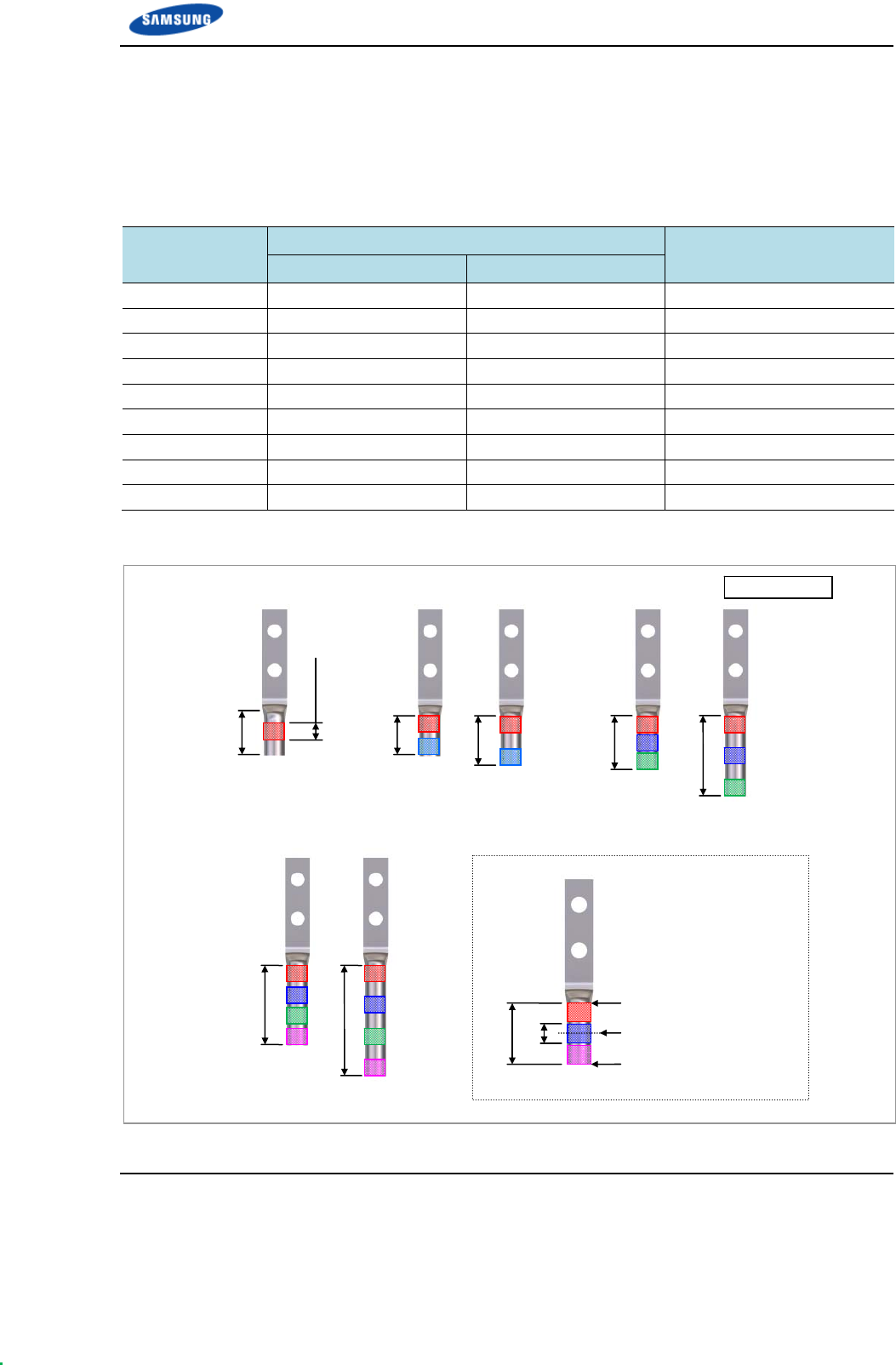
Appendix F Pressure Terminal Assembly
Smart MBS RRH-B8 Installation Manual v3.0 127
©Samsung Proprietary and Confidential
Pressure Reference Table
The pressure reference table used to assemble a pressure terminal to a cable is
shown below.
Table 26. Pressure Reference Table for Pressure Terminal
Category Copper tube length of a pressure terminal Number of pressure points
In. mm
Hand 0.43 in. or less 11 mm or less 1
Hand 0.47~0.59 in. 12~15 mm 2
Hand 0.63~0.91 in. 16~23 mm 3
Hand 0.94~1.26 in. 24~32 mm 4
Hand 1.3 in. or more 33 mm or more 5
Hydraulic 1.18 in. or less 30 mm or less 2
Hydraulic 1.22~1.85 in. 31~47 mm 3
Hydraulic 1.89~2.48 in. 48~63 mm 4
Hydraulic 2.52 in. or more 64 mm or more 5
Figure 82. Pressure Reference Drawing (Handheld Compressor)
[1-spot] [2-spot] [3-spot]
[4-spot]
Unit: in. (mm)
0.43 (11)
0.18 (4.5)
0.47 (12)
0.59 (15)
0.63 (16)
0.91 (23)
0.94 in. (24)
1.26 (32)
0.63 (16)
0.18 (4.5)
Copper Tube Starting
Middle of Copper Tube
A
rbitrary Fixing Reference
Points
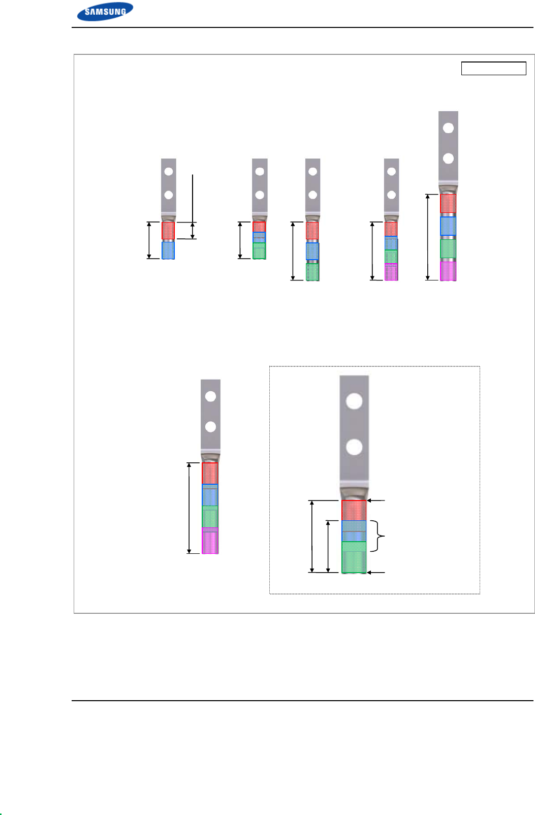
Appendix F Pressure Terminal Assembly
Smart MBS RRH-B8 Installation Manual v3.0 128
©Samsung Proprietary and Confidential
Figure 83. Pressure Reference Drawing (Hydraulic Press)
Unit: in. (mm)
[2-spot] [3-spot] [4-spot]
1.18 (30)
[4-spot]
Copper Tube Starting
Duplicate Pressure
A
rbitrary Fixing
Reference Points
0.53 (13.5)
1.22 (31)
0.53 (13.5)
1.22 (31)
1.85 (47)
1.89 (48)
2.48 (63)
2.52 (64)

Appendix F Pressure Terminal Assembly
Smart MBS RRH-B8 Installation Manual v3.0 129
©Samsung Proprietary and Confidential
Table 27. Compressor Specifications per Cable Thickness
Cable Size Press Size
AWG mm2 Small Handheld Press Large Handheld Press
(AK-38, 100)
Hydraulic Press
(IZUMI Hexagonal Dies)
12 2.5 2 X X
10 4 2 X X
8 6 5.5 X X
6 10 8 8 X
4 16 14 14 16
2 25 22 22 25
1 35 38 38 35
1/0 50 X 60 50
3/0 70 X 80 70
4/0 95 X 100 95~300
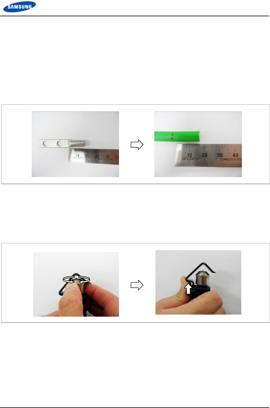
Appendix F Pressure Terminal Assembly
Smart MBS RRH-B8 Installation Manual v3.0 130
©Samsung Proprietary and Confidential
Assembling Pressure Terminal
The procedures for assembling a pressure terminal to a cable are as follows:
Strip the Cable Sheath
1 After checking the inside length of a pressure terminal, mark the cable.
Figure 84. Stripping Cable Sheath (1)
2 Adjust the length of a cutter blade according to the sheath thickness of the
cable.
3 Push the clamp with a thumb according to the cable size to secure a space for
the cable.
Figure 85. Stripping Cable Sheath (2)

Appendix F Pressure Terminal Assembly
Smart MBS RRH-B8 Installation Manual v3.0 131
©Samsung Proprietary and Confidential
4 Put a cable into a clamp, locate a blade on a marking position, and push it into
the sheath.
5 Align the stripper to be perpendicular to the cable and rotate it more than two
laps.
Figure 86. Stripping Cable Sheath (3)
6 Push the lever of the stripper to the right to turn its blade at 90°.
Figure 87. Stripping Cable Sheath (4)
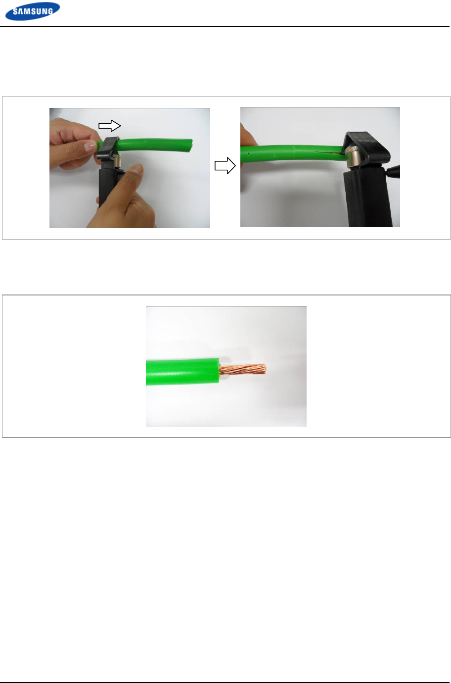
Appendix F Pressure Terminal Assembly
Smart MBS RRH-B8 Installation Manual v3.0 132
©Samsung Proprietary and Confidential
7 Move the stripper up to the end of cable while maintaining the stripper to be
perpendicular to the cable.
Figure 88. Stripping Cable Sheath (5)
8 Remove the sheath.
Figure 89. Stripping Cable Sheath (6)
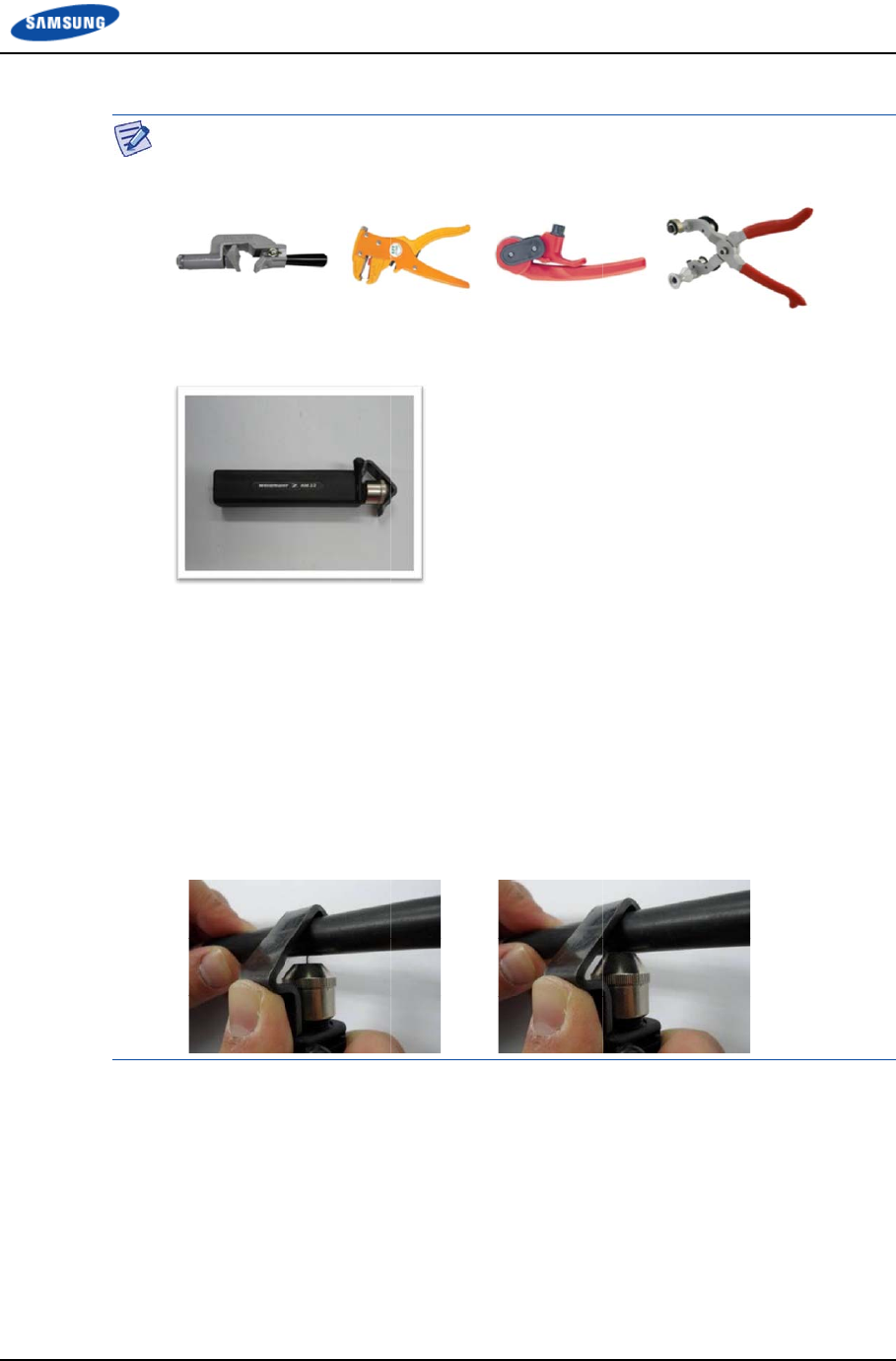
Smart M
B
©Samsu
n
B
S RRH-B8 I
n
n
g Proprietar
y
A
T
T
fo
0
-
a
-
-
n
stallation Ma
y
and Confide
n
A
wire stripp
T
herefore, re
f
T
he specific
a
fo
llows:
Vender: W
e
Model: We
i
Specificati
o
0
.18 in. (4.5
m
To prevent
t
a
djust the le
n
Make sure
t
Rotate the
w
n
ual v3.0
n
tial
er is used di
f
f
er to the us
e
a
tions and ca
u
e
idmulle
r
i
dmulle
r
-A
M
o
ns: For oute
m
m) clothin
g
t
he cutter bl
a
n
gth of cutte
r
t
hat the cutte
w
ire stripper
[X]
f
ferently de
p
e
r manual e
n
utions of a
w
M
25 (Order
N
e
r diameter 0
g
cutting de
p
a
de of a wir
e
r
blade by c
h
e
r blade goes
perpendicul
a
App
e
p
ending on i
t
n
closed with
w
ire stripper
N
o-9001080
0
.24-0.94 in.
(
p
th
e
stripper fro
m
h
ecking the c
into the cab
a
rly to the c
a
e
ndix F Pres
s
t
s manufact
u
the product.
described in
0
00)
(
6-24 mm)
P
m
touching
t
a
ble sheath
t
le sheath co
m
a
ble.
[O]
s
ure Terminal
u
rer or type.
n
this manual
P
VC clothin
g
t
he cable co
n
t
hickness.
m
pletely.
Assembly
133
are as
g
Up to
n
ductor,
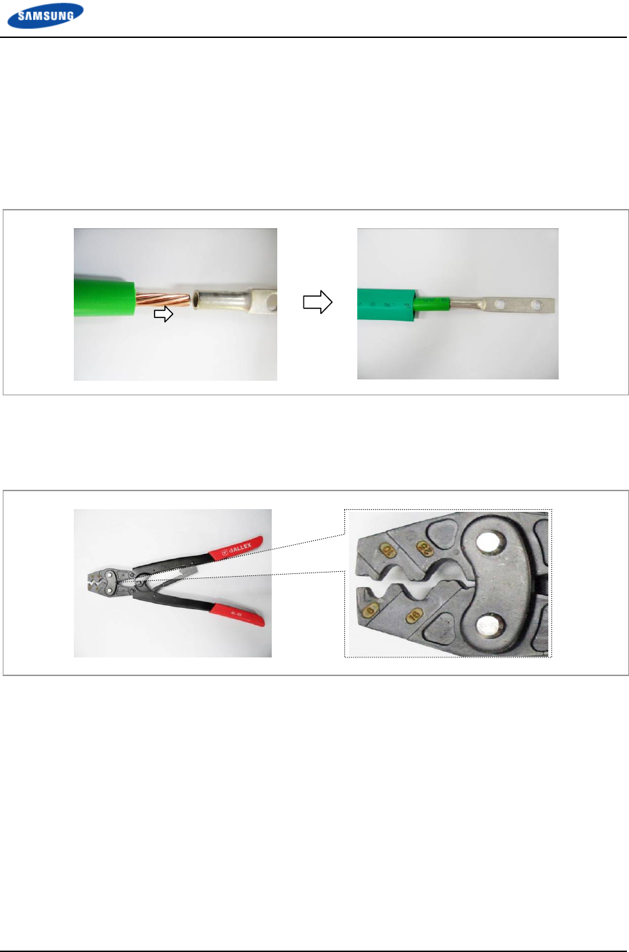
Appendix F Pressure Terminal Assembly
Smart MBS RRH-B8 Installation Manual v3.0 134
©Samsung Proprietary and Confidential
Fixing Pressure Terminal (Handheld Compressor)
1 Insert the conductor of the cable with the sheath stripped to the internal end of
pressure terminal.
For a ring type pressure terminal, push it in until the conduct comes out 0.04 in.
(1 mm) from the end of the terminal.
Figure 90. Fixing Pressure Terminal_Handheld Compressor (1)
2 From the holes of handheld compressor, select one that fits to the pressure
terminal.
Figure 91. Fixing Pressure Terminal_Handheld Compressor (2)
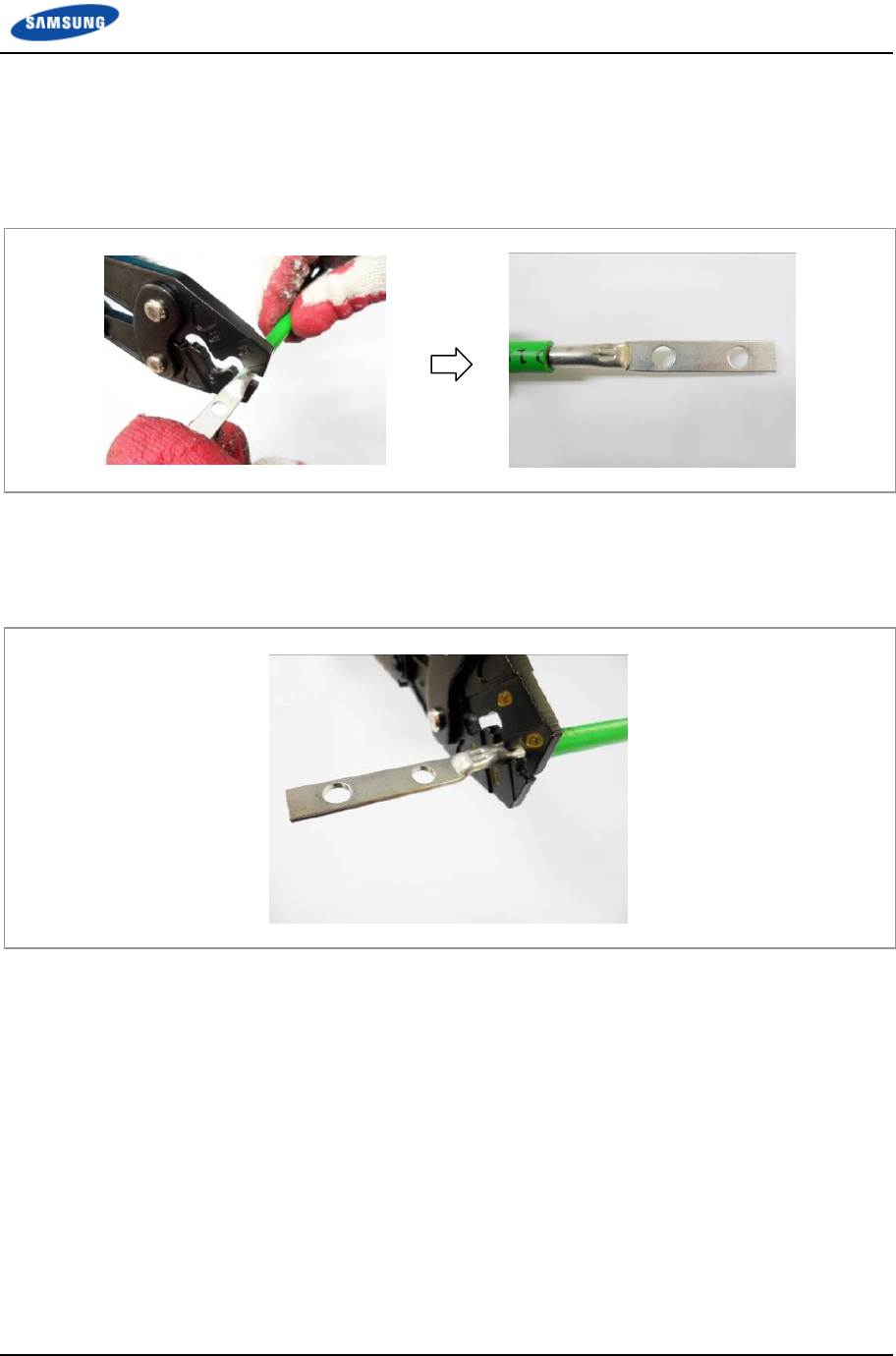
Appendix F Pressure Terminal Assembly
Smart MBS RRH-B8 Installation Manual v3.0 135
©Samsung Proprietary and Confidential
3 Insert the pressure terminal to the selected hole.
4 Fix the pressure terminal and cable temporarily so the position can be changed
later by pressing the compressor.
Figure 92. Fixing Pressure Terminal_Handheld Compressor (3)
5 After complementary of the cable which is temporary fixed, align it to the hole
and firmly compress the pressure terminal to secure fix it.
Figure 93. Fixing Pressure Terminal_Handheld Compressor (4)
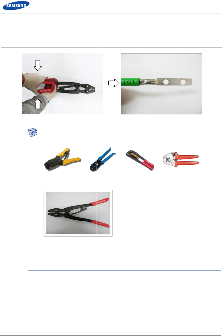
Smart M
B
©Samsu
n
Figure 9
4
B
S RRH-B8 I
n
n
g Proprietar
y
6
4
. Fixing Pre
s
A
T
T
a
2
n
stallation Ma
y
and Confide
n
6
Separate
handle o
f
s
sure Termi
n
A
handheld
c
T
herefore, re
f
T
he specific
a
a
re as follow
s
Vender: G
A
Model: GL
-
Specificati
o
2
5 mm2 (DI
N
n
ual v3.0
n
tial
the pressure
f
compresso
r
n
al_Handhel
d
c
ompressor i
s
f
er to the us
e
a
tions and ca
u
s
:
A
LLEX
-
2045A-22
o
n: 5.5 mm2,
N
)
terminal fr
o
r
until a clic
k
d
Compress
o
s
used differ
e
e
r manual e
n
utions of a
h
8 mm2, 14
m
App
e
o
m the hand
h
k
ing sound i
s
r
(
5)
e
ntly depen
d
n
closed with
h
andheld co
m
m
m2, 22 mm
2
e
ndix F Pres
s
h
eld compre
s
s
heard to be
d
ing on its
m
the product.
m
pressor des
c
2
(JIS), 6 m
m
s
ure Terminal
s
sor. Press d
o
unlocked.
m
anufacturer
c
ribed in thi
s
m
2, 10 mm2,
Assembly
136
o
wn the
o
r type.
s
manual
16 mm2,

Appendix F Pressure Terminal Assembly
Smart MBS RRH-B8 Installation Manual v3.0 137
©Samsung Proprietary and Confidential
Fixing Pressure Terminal (Hydraulic Press)
1 Among the dies of the hydraulic press, select one that fits to the pressure
terminal.
Figure 95. Fixing Pressure Terminal_Hydraulic Press (1)
2 Assemble the dies to the pressing area of the compressor.
Figure 96. Fixing Pressure Terminal_Hydraulic Press (2)
②
①
Dies
Hydraulic Press

Appendix F Pressure Terminal Assembly
Smart MBS RRH-B8 Installation Manual v3.0 138
©Samsung Proprietary and Confidential
3 Insert the pressure terminal into the pressing area and fix it slightly by aligning
it to the end of cable sheath.
Figure 97. Fixing Pressure Terminal_Hydraulic Press (3)
4 Move the compressor lever up and down to press the pressure terminal firmly.
Figure 98. Fixing Pressure Terminal_Hydraulic Press (4)
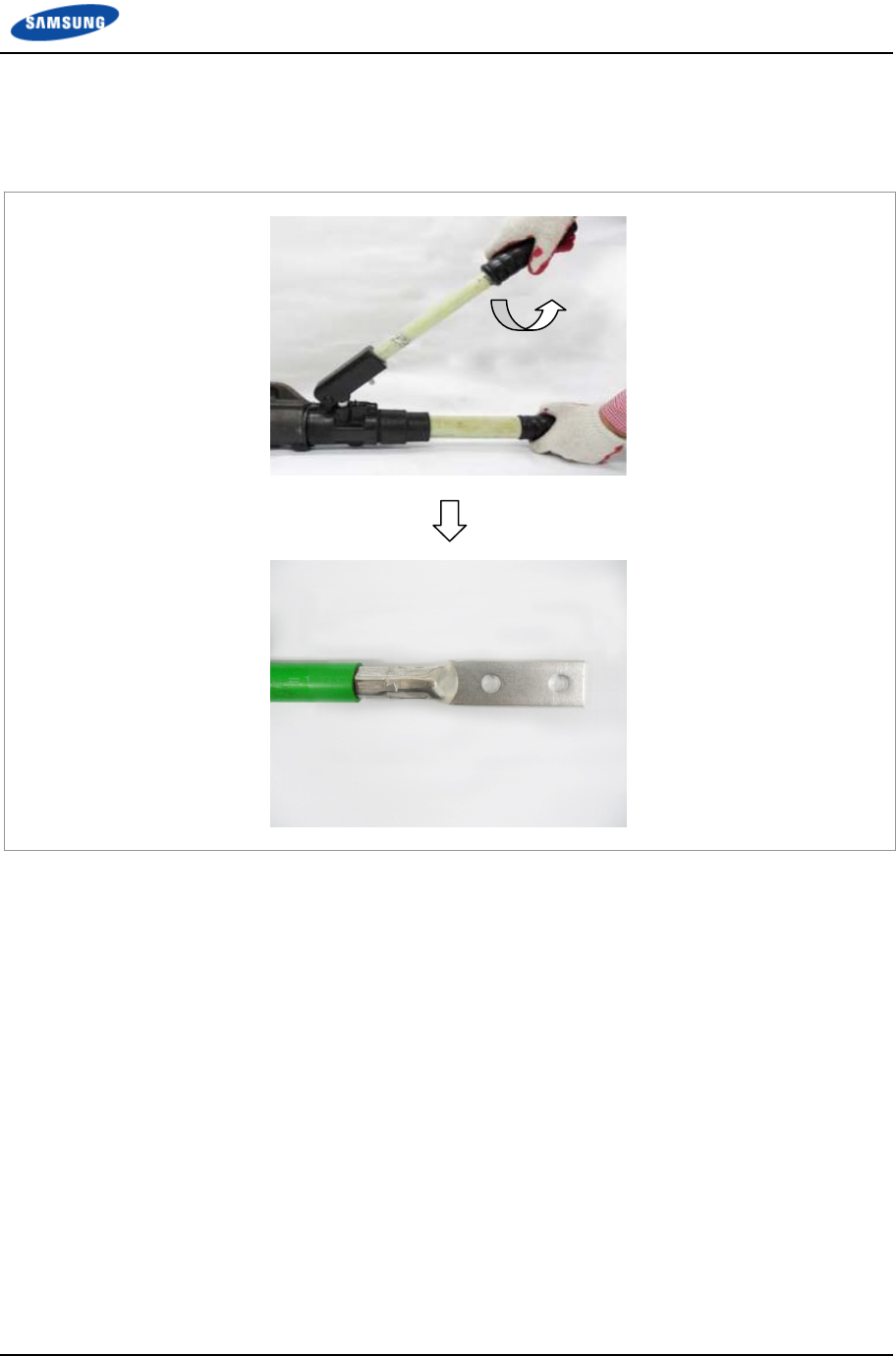
Appendix F Pressure Terminal Assembly
Smart MBS RRH-B8 Installation Manual v3.0 139
©Samsung Proprietary and Confidential
5 Turn the top compressing lever clockwise and then push it down. When the
pressing area of compressor is loosened, remove the pressure terminal.
Figure 99. Fixing Pressure Terminal_Hydraulic Press (5)
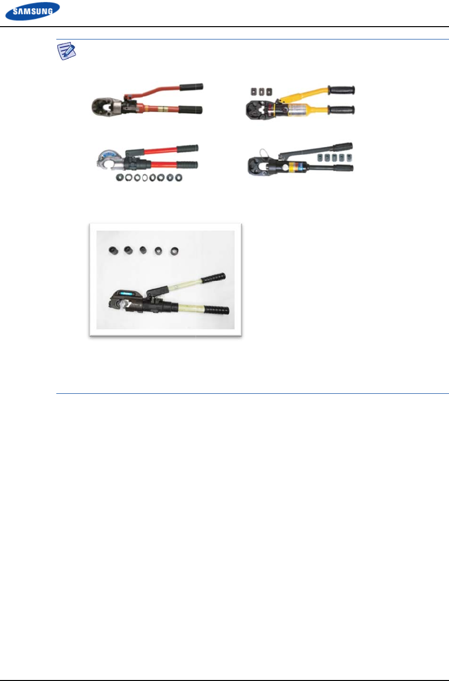
Smart M
B
©Samsu
n
B
S RRH-B8 I
n
n
g Proprietar
y
A
T
T
fo
n
stallation Ma
y
and Confide
n
A
hydraulic
p
T
herefore, re
f
T
he specific
a
fo
llows:
Vender: IZ
U
Model: IZ
U
Specificati
o
n
ual v3.0
n
tial
p
ress is used
f
er to the us
e
a
tions and ca
u
U
MI
U
MI-EP-510
B
o
n: Circular
3
differently
d
e
r manual e
n
utions of a
h
B
3
2~160 (SQ
)
App
e
d
epending o
n
n
closed with
h
ydraulic pre
)
Hex 14~32
e
ndix F Pres
s
n
its manufa
c
the product.
s
s described
5
(SQ)
s
ure Terminal
c
turer or typ
e
in this man
u
Assembly
140
e
.
u
al are as
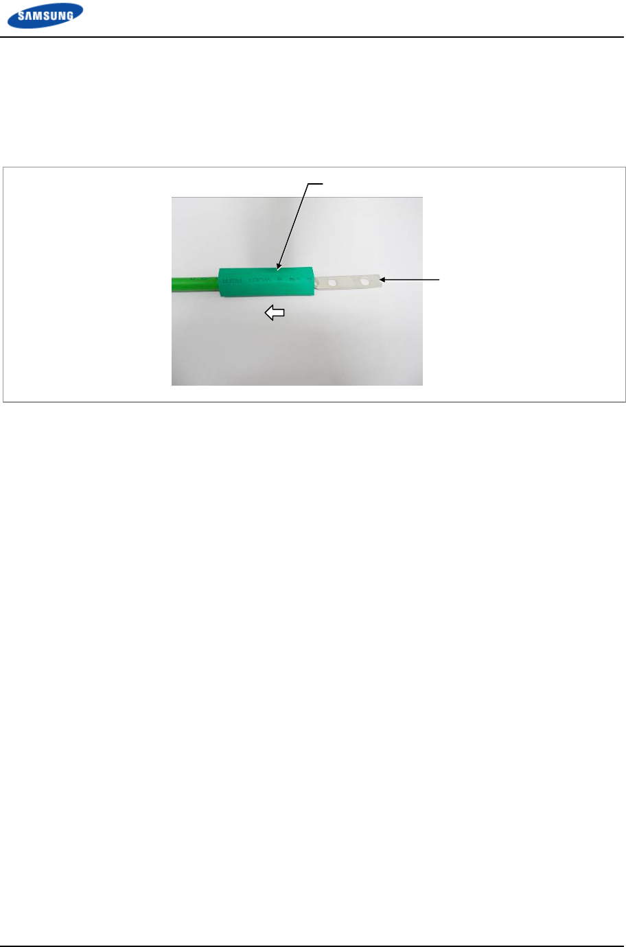
Appendix F Pressure Terminal Assembly
Smart MBS RRH-B8 Installation Manual v3.0 141
©Samsung Proprietary and Confidential
Assembling Heat Shrink Tube
1 After assembling a pressure terminal, move the heat shrink tube, inserted to
the cable, to the end of pressure terminal copper tube.
Figure 100. Assembling Heat Shrink Tube (1)
2 Set the temperature of the heat gun to 356~392°F (180~200°C).
3 Locate a heat shrink tube to cover the entire copper tube of the pressure
terminal.
4 Rotate a heat gun 360° to apply heat evenly to shrink the tube.
(Because the pressure terminal and the cable is hot due to the heat of a heating
gun, be careful not to have a burn.)
Heat Shrink Tube
Pressure Terminal

Appendix F Pressure Terminal Assembly
Smart MBS RRH-B8 Installation Manual v3.0 142
©Samsung Proprietary and Confidential
Figure 101. Assembling Heat Shrink Tube (2)
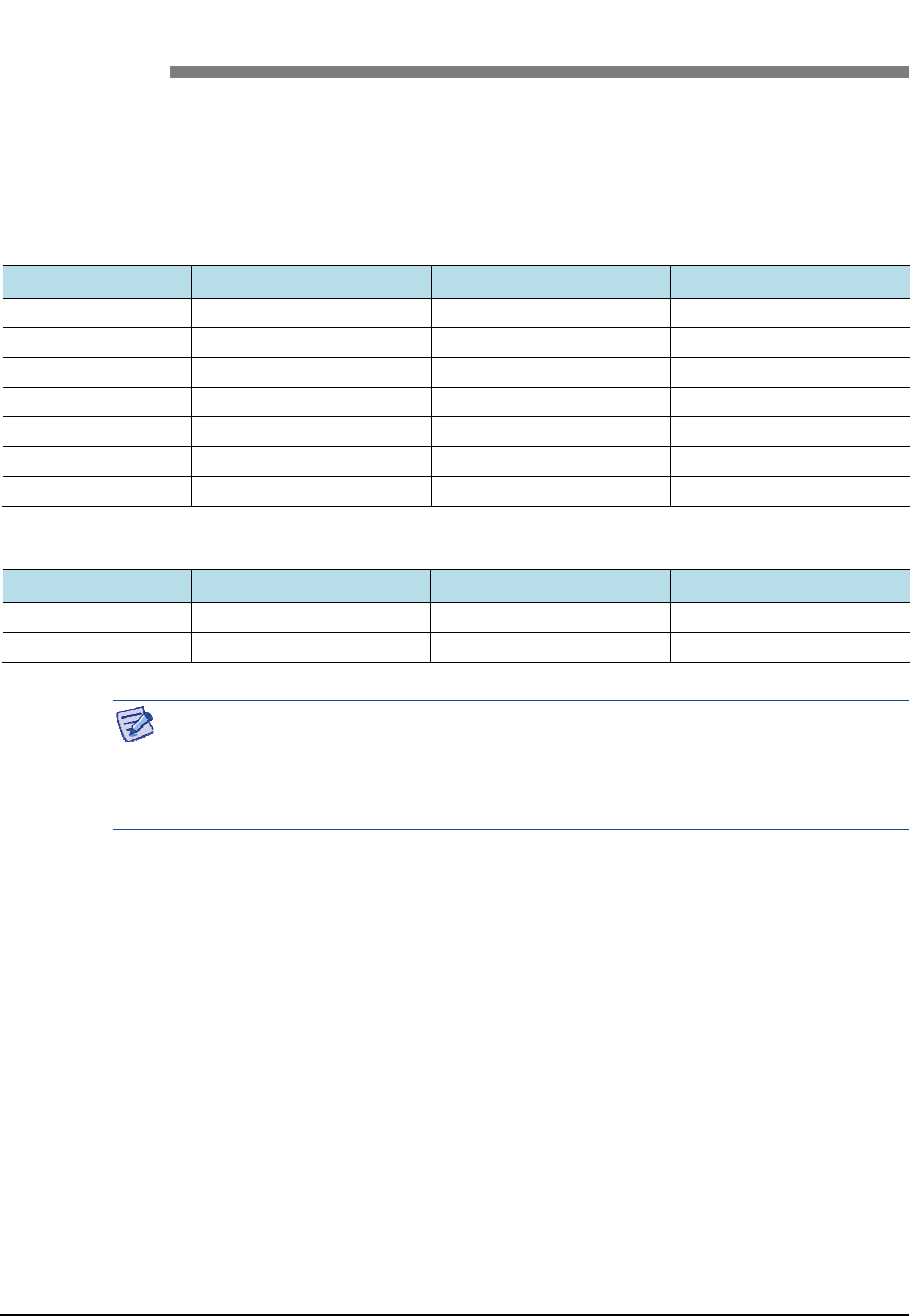
Smart MBS RRH-B8 Installation Manual v3.0 143
©Samsung Proprietary and Confidential
Appendix G Standard Torque
When you fasten the bolt, refer to the standard torque value below to prevent the
equipment and bolt from damage and fasten tightly. When the torque value for
each connection part is defined already, refer to the defined value.
Table 28. Standard Torque Value for Tightening Bolts
Bolt Spec. Torque (kgf.cm) Torque (N.m) Torque (lbf.ft)
M3 4.08~6.12 0.40~0.60 0.29~0.44
M4 9.52~14.28 0.93~1.40 0.69~1.03
M5 20.0~30.0 1.96~2.94 1.45~2.17
M6 33.28~49.92 3.26~4.90 2.41~3.61
M8 82.4~123.6 8.08~12.12 5.96~8.94
M10 166.4~249.6 16.32~24.48 12.03~18.05
M12 292.0~438.0 28.64~42.65 21.11~31.67
Table 29. Brass Bolts Torque
Bolt Spec. Torque (kgf.cm) Torque (N.m) Torque (lbf.ft)
M6 29.98 ± 10 % 2.94 ± 10 % 2.17 ± 10 %
M8 64.26 ± 10 % 6.3 ±1 0 % 4.16 ± 10 %
The torque value can change depending on the equipment and materials, properties
and specifications of the fastening bolts. Therefore, you must check the
appropriate torque value of each equipment and fastening bolts according to its
spec.

Smart MBS RRH-B8
Installation Manual
Document Version 3.0
©2013
~
2015 Samsung Electronics Co., Ltd.
All rights reserved.