Samsung Electronics Co SMM-2CD0480800 Remote Radio Head is an 800MHz wireless telecom system User Manual
Samsung Electronics Co Ltd Remote Radio Head is an 800MHz wireless telecom system Users Manual
UserManual.wiki
>
Samsung Electronics Co
>
SMM 2CD0480800 User Manual
Users Manual
Navigation menu
Upload a User Manual
Namespaces
Wiki Guide
HTML
PDF
Info
Views
User Manual
Discussion / Help
Navigation

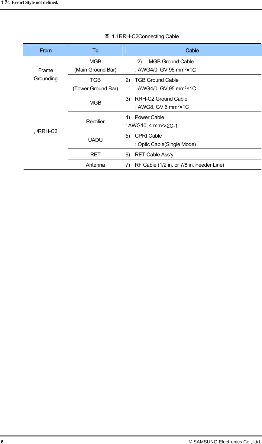
![Smart MBS RRH-P4 설치 매뉴얼/Ed.00 © SAMSUNG Electronics Co., Ltd. 5 1.2 Cable Connection Fig1.3Cabling Diagram 3) RRH-C2 Ground Cable [RF Antenna] [MGB] 2) TGB Ground Cable[TGB] Feeder Line Ground Cable (Ground Kit/ with over 7/8 in. Feeder Line) ※ TGB and Ground Kit is required when over 7/8 in. Feeder Line is used. [Rectifier] [UADU] 4) Power Cable 1) MGB Ground Cable 5) CPRI Cable 6) RET Cable 7) RF Cable](https://usermanual.wiki/Samsung-Electronics-Co/SMM-2CD0480800/User-Guide-1538618-Page-9.png)


![Smart MBS RRH-P4 설치 매뉴얼/Ed.00 © SAMSUNG Electronics Co., Ltd. A-19 부록 A. Standard Torque F.1 Standard Torque for Bolt 볼트 조임 시, 장비나 볼트 등의 파손을 방지하고 및 견고한 체결을 위하여 아래 표준 토크 값을 참조하여 설치한다. (단, 체결부위 별 토크 값이 정의되어 있는 경우, 정의 된 토크 값을 기준으로 한다.) 표 F.1 볼트 조임 시 표준 토크 볼트 규격 Torque[kgf.cm] Torque[N.m] M3 4.59~5.61 0.45~0.55 M4 10.98~13.42 1.08~1.32 M5 21.15~15.85 2.07~2.54 M6 38.16~46.64 3.74~4.58 M8 91.8~112.2 9.01~11.01 M10 180~220 17.66~21.58 M12 307.8~376.2 30.20~36.91](https://usermanual.wiki/Samsung-Electronics-Co/SMM-2CD0480800/User-Guide-1538618-Page-29.png)