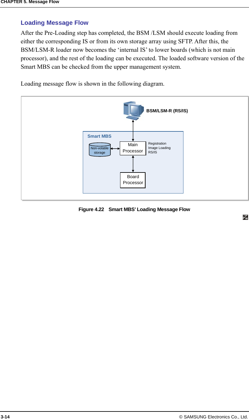
Samsung Electronics Co SMM-BMAA022001 Smart MBS (Smart Multi-modal Base Station) User Manual

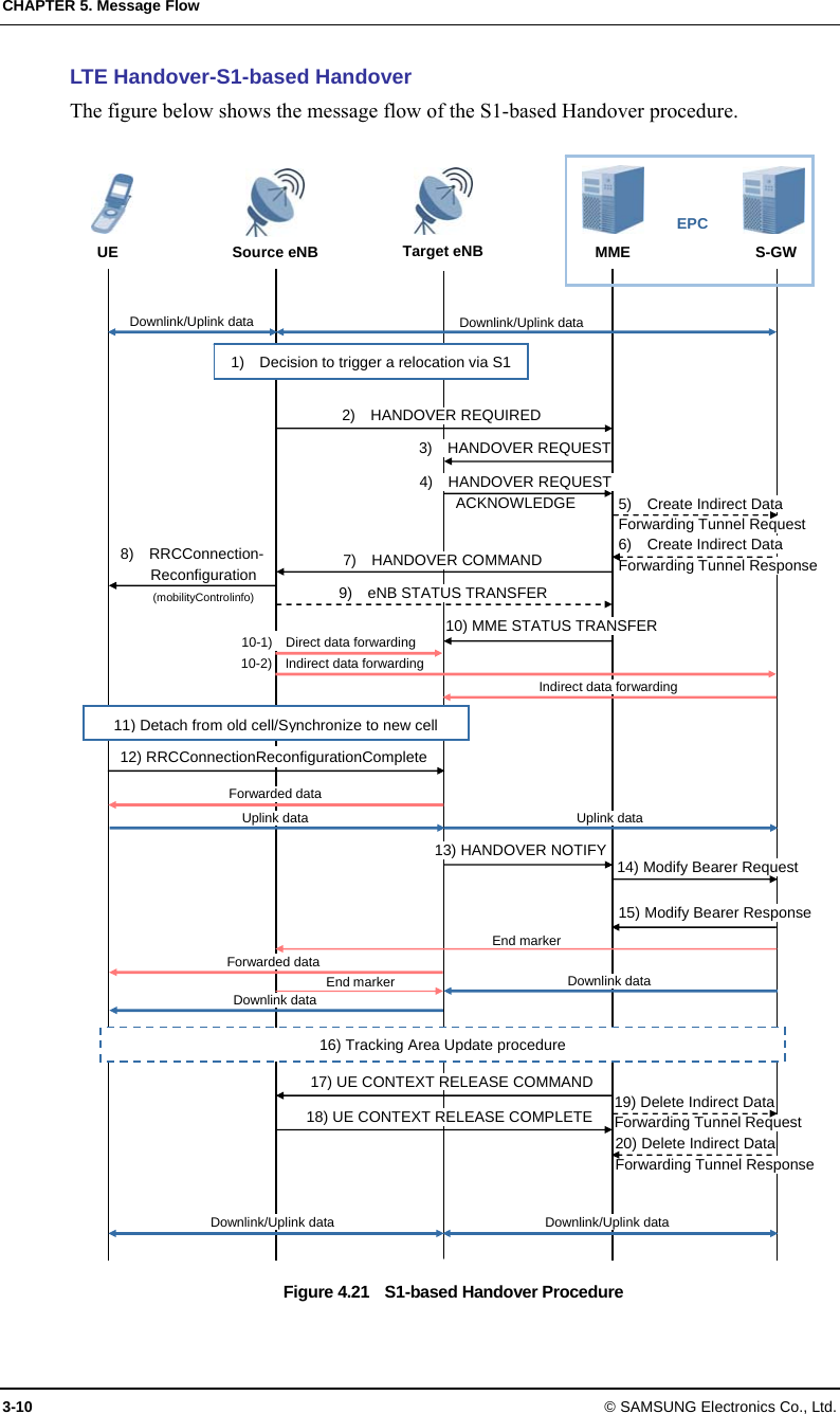
Samsung Electronics Co Ltd Smart MBS (Smart Multi-modal Base Station)

User Manual

 Ver.     1.0        LTE Smart MBS System Description
    COPYRIGHT This description is proprietary to SAMSUNG Electronics Co., Ltd. and is protected by copyright. No information contained herein may be copied, translated, transcribed or duplicated for any commercial purposes or disclosed to the third party in any form without the prior written consent of SAMSUNG Electronics Co., Ltd.   TRADEMARKS Product names mentioned in this description may be trademarks and/or registered trademarks of their respective companies.                       This description should be read and used as a guideline for properly installing and operating the product.  This description may be changed for the system improvement, standardization and other technical reasons without prior notice.   If you need updated manuals or have any questions concerning the contents of the manuals, contact our Document Center at the following address or Web site:  Address: Document Center 3rd Floor Jeong-bo-tong-sin-dong. Dong-Suwon P.O. Box 105, 416, Maetan-3dong Yeongtong-gu, Suwon-si, Gyeonggi-do, Korea 442-600 Homepage: http://www.samsungdocs.com ©2012 SAMSUNG Electronics Co., Ltd.    All rights reserved.
LTE/CDMA Smart MBS System Description © SAMSUNG Electronics Co., Ltd.  I INTRODUCTION      Purpose This description introduces characteristics, features, and structure for Smart MBS   Document Content and Organization This description consists of 4 Chapters and Abbreviation as follows.  CHAPTER 1. Overview of Samsung MBS System    Samsung Smart MBS Introduction  Samsung Smart MBS Network Configuration    Samsung Smart MBS System Feature    CHAPTER 2. Overview of Smart MBS  Smart MBS System Introduction  Smart MBS Main Feature  Smart MBS Specification  Interface between the Systems  CHAPTER 3. Smart MBS System Structure  Hardware Structure  Software Structure  CHAPTER 4. Message Flow  LTE Call Processing Message Flow  Loading flow  ABBREVIATION Provides definition for acronyms used in this description.
INTRODUCTION II © SAMSUNG Electronics Co., Ltd.  Conventions The following types of paragraphs contain special information that must be carefully read and thoroughly understood. Such information may or may not be enclosed in a rectangular box, separating it from the main text, but is always preceded by an icon and/or a bold title.   NOTE   Indicates additional information as a reference.    Revision History EDITION  DATE OF ISSUE  REMARKS 1.0 2012. 02.  First Edition
LTE/CDMA Smart MBS System Description © SAMSUNG Electronics Co., Ltd.  III TABLE OF CONTENTS   INTRODUCTION I Purpose .................................................................................................................................................. I Document Content and Organization..................................................................................................... I Conventions........................................................................................................................................... II Revision History..................................................................................................................................... II CHAPTER 1. Overview of Samsung MBS System 오류!  책갈피가 정의되어 있지 않습니다. 1.1 Introduction to Samsung MBS System................... 오류!  책갈피가 정의되어 있지 않습니다. 1.2 Samsung MBS System Network Configuration .................................................................. 1-1 1.2.1 System Network Configuration................................오류!  책갈피가 정의되어 있지 않습니다. 1.2.2 LTE System Network Configuration .....................................................................................1-1 1.3 Samsung MBS System Feature............................................................................................ 1-5 1.3.1 System Feature .......................................................오류!  책갈피가 정의되어 있지 않습니다. 1.3.2 LTE System Feature.............................................................................................................1-5 CHAPTER 2. Smart MBS Abstract  1-1 2.1 Smart MBS System Introduction.......................................................................................... 1-1 2.1.1 System Feature .......................................................오류!  책갈피가 정의되어 있지 않습니다. 2.1.2 LTE System Feature.............................................................................................................1-3 2.2 Smart MBS Main Feature....................................................................................................... 1-6 2.2.1 Physical Layer Processing Function ....................................................................................1-6 2.2.2 Call Processing Function......................................................................................................1-8 2.2.3 IP Processing Function.......................................................................................................1-10 2.2.4 Operation and Maintenance Function................................................................................1-10 2.3 Specifications ...................................................................................................................... 1-13 2.4 Interface between Systems................................................................................................. 1-15 2.4.1 Interface Structure....................................................오류!  책갈피가 정의되어 있지 않습니다. 2.4.2 LTE Interface Structure.......................................................................................................1-15 2.4.3 Physical Interface Operation Method.................................................................................1-20
TABLE OF CONTENTS IV © SAMSUNG Electronics Co., Ltd. CHAPTER 3. Smart MBS Structure  2-1 3.1  Smart MBS Hardware Structure..............................................................................................2-1 3.1.2 Internal Configuration of System (LTE) ................................................................................2-4 3.1.3 UADU....................................................................................................................................2-6 3.1.4 LRU..................................................................................................................................... 2-11 3.1.5 Power Device......................................................................................................................2-13 3.1.5 Environment Devices..........................................................................................................2-15 3.1.6 Interface structure...............................................................................................................2-17 3.2 Smart MBS Software Structure ...........................................................................................2-21 3.2.1 Software Structure .................................................. 오류!  책갈피가 정의되어 있지 않습니다. 3.2.2 LTE Software Structure.......................................................................................................2-21 CHAPTER 4. Message Flow  3-1 4.1 Call Processing Message Flow .............................................................................................3-1 4.1.1 Call Processing Message Flow.............................. 오류!  책갈피가 정의되어 있지 않습니다. 4.1.2 LTE Call Processing Message Flow.....................................................................................3-1 4.2 Loading Flow ........................................................................................................................3-13 ABBREVIATION I A ~ C....................................................................................................................................................... I D ~ F...................................................................................................................................................... II G ~ M.................................................................................................................................................... III N ~ P.....................................................................................................................................................IV Q ~ S......................................................................................................................................................V T ~ W ....................................................................................................................................................VI   LIST OF FIGURES Figure 1.1    Network Configuration of Samsung MBS System오류!  책갈피가 정의되어 있지 않습니다. Figure 1.3    LTE System Network Configuration .......................................................................1-1 Figure 1.4    System Functional Structure ......................오류!  책갈피가 정의되어 있지 않습니다. Figure 1.5    Functions of E-UTRAN and EPC ...........................................................................1-5  Figure 2.1    Protocol Stack between BTS and MS ........오류!  책갈피가 정의되어 있지 않습니다. Figure 2.2    Protocol Stack between BTS and BSC ......오류!  책갈피가 정의되어 있지 않습니다. Figure 2.3    Protocol Stack between BTS and BSM......오류!  책갈피가 정의되어 있지 않습니다.
  LTE/CDMA Smart MBS System Description/Ver.1.0 © SAMSUNG Electronics Co., Ltd.  V Figure 2.4    LTE Interface Structure........................................................................................ 1-15 Figure 2.5    Protocol Stack between UE and eNB.................................................................. 1-16 Figure 2.6    Protocol Stack between eNB and EPC................................................................ 1-17 Figure 2.7    Protocol Stack between eNB and MME............................................................... 1-17 Figure 2.8    Protocol Stack between eNBs (User Plane)........................................................ 1-18 Figure 2.9    Protocol Stack between eNBs (Control Plane).................................................... 1-18 Figure 2.10    Protocol Stack between eNB and LSM.............................................................. 1-19  Figure 3.1    Smart MBS Configuration...................................................................................... 2-2 Figure 3.4    LTE 6 Sector Configuration ................................................................................... 2-3 Figure 3.6    Internal Configuration of System (LTE) ................................................................. 2-4 Figure 3.7    UADU Configuration.................................. 오류!  책갈피가 정의되어 있지 않습니다. Figure 3.8    Cooling Structure of the UADU (FANM-C4)......................................................... 2-10 Figure 3.9    Power Device Configuration................................................................................ 2-13 Figure 3.10    Power Structure................................................................................................. 2-14 Figure 3.10    Configuration of Environment Devices .............................................................. 2-15 Figure 3.12    Hardware Interface structure of UADU (LTE) .................................................... 2-19 Figure 3.13    Hardware Interface structure of LRU-C2........................................................... 2-20 Figure 3.18  LTE Software Structure ..................................................................................... 2-21 Figure 4.15    Attach Process .................................................................................................... 3-2 Figure 4.16    Service Request Process by UE ......................................................................... 3-4 Figure 4.17    Service Request Process by Network ................................................................. 3-5 Figure 4.18    Detach Process by UE ........................................................................................ 3-6 Figure 4.19    Detach Process by MME..................................................................................... 3-7 Figure 4.20  X2-based Handover Procedure........................................................................... 3-8 Figure 4.21    S1-based Handover Procedure......................................................................... 3-10 Figure 4.22    Smart MBS’ Loading Message Flow ................................................................. 3-14
LTE/CDMA Smart MBS System Description © SAMSUNG Electronics Co., Ltd.  1-1 1.2  Samsung MBS System Network Configuration Samsung MBS system plays a role as LTE base station in a network where LTE systems co-exist. Samsung MBS System is configured as follows:   1.2.2  LTE System Network Configuration LTE network of Samsung MBS system incorporates base station (eNB), packet core (EPC), LSM. The LTE system consists of multiple base stations (eNB: Evolved UTRAN Node-B) and EPC(MME, S-GW/P-GW) provides functionality for UE to connect to external network as subnet of PDN. In addition, LTE system provides LSM and self-optimization function for operation and maintenance of eEB.  LTE network architecture of Samsung MBS system is as follows:  Figure 1.3  LTE System Network Configuration  Evolved UTRAN Node-B (eNB) eNB is a system located between mobile terminal (User Equipment, UE) and EPC, and it handles the packet calls by connecting to UE wirelessly in accordance with LTE air standard. eNB executes various functions including Tx/Rx of wireless signal, modulation/demodulation of packet traffic, packet scheduling for efficient use of RF resources, Hybrid Automatic Repeat request (HARQ) and Automatic Repeat request (ARQ) process, Packet Data Convergence Protocol (PDCP) of compressed packet header, UE UECG  PCRF HSS/SPR Uu S1-U  S1-MME EMS LSM-C Smart MBS Smart MBSEMS LSM-R MSS OCS EPC RMI S5/S8 Gx S-GW Sp TL1 MME P-GW Gy S11  S6a Gz Gz S1 S10 PDN X2-C X2-U SNMP/FTP/UDP
CHAPTER 1. Smart MBS Abstract 1-2 © SAMSUNG Electronics Co., Ltd. and wireless resource control.   Also, it synchronizes with EPC to execute handover.    Evolved Packet Core (EPC) EPC is a system between eNB and PDN. It incorporates MME, S-GW/P-GW.  MME: MME handles control message with eNB via Non-Access Stratum (NAS) signaling protocol, and performs management of mobility for UE, management of tracking area list, control plane function such as bearer and session management.  S-GW: S-GW plays role as anchor on user plane between 2G/3G access system and LTE system. S-GW manages/processes packet transmit layer of downlink/uplink data.  P-GW: P-GW allocates IP address to UE, plays role as anchor for mobility between LTE system and non-3GPP access systems, manages accounting for different service levels, and handles management/modification of the throughput rate.  LTE System Manager (LSM) LSM provides the following functions.  LTE System Manager-Radio (LSM-R)   The LSM-R provides an operator interface which the operator can use for operation and maintenance of the eNB. It also provides functions for software management, configuration management, performance management and fault management, and Self Organizing Network (SON) server.  LTE System Manager-Core (LSM-C) The LSM-C provides an operator interface which the operator can use for operation and maintenance of the MME, S-GW and P-GW.  Home Subscriber Server (HSS) The HSS is a database management system that stores and manages the parameters and location information for all registered mobile subscribers. The HSS manages key data, such as the mobile subscriber’s access capability, basic and supplementary services, and provides a routing function to the called subscriber.  Master SON Server (MSS) MSS is a higher node of local SON server. MSS interworks with local SON server to optimize the interworking in regards to Multi-LSM. MSS is a function that is interworking with the operator Operations Support System (OSS), and the availability of this optional function will be decided after discussion with operator.  Policy Charging & Rule Function (PCRF) The PCRF server creates policy rules to dynamically apply the QoS and accounting policies differentiated by service flow, or creates the policy rules that can be applied commonly to multiple service flows. The IP edge includes the Policy and Charging Enforcement Function (PCEF), which allows application of policy rules received from the
  LTE/CDMA Smart MBS System Description/Ver.1.0 © SAMSUNG Electronics Co., Ltd.  1-3 PCRF server to each service flow.
CHAPTER 1. Smart MBS Abstract 1-4 © SAMSUNG Electronics Co., Ltd. Online Charging System (OCS) If subscribers (with online accounting information) makes call, subscriber’s accounting information is sent/received.  Offline Charging System (OFCS) OFCS stores the offline accounting data, and provides accounting data per each subscriber.
  LTE/CDMA Smart MBS System Description/Ver.1.0 © SAMSUNG Electronics Co., Ltd.  1-5 1.3  Samsung MBS System Feature  1.3.2  LTE System Feature The eNB manages UEs which are in connected mode at the Access Stratum (AS) level. The MME manages UEs which are in idle mode at the Non-Access Stratum (NAS) level, and the P-GW manages user data at the NAS level as well as working with other networks.    The functional architecture of E-UTRAN eNB, MME, S-GW, and P-GW according to the 3GPP standard is shown below. The eNB is structured in layers while the EPC is not.  Figure 1.5  Functions of E-UTRAN and EPC  eNB The eNB serves the Evolved UTRAN (E-UTRAN), a wireless access network in the LTE system. The eNBs are connected via the X2 interface whereas the eNB and EPC are connected via S1 interface. The eNB’s wireless protocol layers are divided into Layer 2 and Layer 3.   Layer 2 is subdivided into the Media Access Control (MAC) layer, Radio Link Control (RLC) layer, and PDCP layer, each operating independently. Layer 3 has the RRC layer.  The MAC sublayer distributes wireless resources to each bearer according to its priority, and carries out the multiplexing function and the HARQ function for the data received from the multiple upper logical channels.  The RLC layer performs the following functions. S1 MME NAS Security Idle State Mobility Handling EPS Bearer Control S-GW Mobility Anchoring P-GW Packet Filtering UE IP address allocation EPC  Internet eNB Inter Cell RRM RB Control Connection Mobility Control Radio Admission Control eNB Measurement Configuration & Provision Dynamic Resource Allocation (Scheduler) RRC PDCP RLC MAC PHY E-UTRAN
CHAPTER 1. Smart MBS Abstract 1-6 © SAMSUNG Electronics Co., Ltd.  Segmentation and reassembly on the data received from the PDCP sublayer into the size specified by the MAC sublayer  Restoration of the transmission by resending in case of transmission failure at lower-level layers (ARQ)  Re-ordering of the HARQ operation of the MAC sublayer  The PDCP layer carries out the following functions.    Header compression and decompression  Ciphering and deciphering of the user plane and control plane data  Integrity protection and verification of the control plane data  Data transmission of data, including serial numbers  Removing timer-based and duplicate data  The RRC layer is responsible for managing mobility in the wireless access network, keeping and controlling the Radio Bearer (RB), managing RRC connections, and sending system information.  Mobility Management Entity (MME) The MME works with the E-UTRAN (eNB), handling S1 Application Protocol (S1-AP) signaling messages in the Stream Control Transmission Protocol (SCTP) base to control call connections between the MME and eNB as well as handling NAS signaling messages in the SCTP base to control mobility and call connections between the UE and EPC.   The MME also works with the HSS to obtain, modify and authenticate subscriber information, and works with the S-GW to request assignment, release and modification of bearer paths for data routing and forwarding using the GTP-C protocol. The MME can work with the 2G and 3G systems, SGSN, and MSC to provide mobility, Handover (HO), Circuit Service (CS) fallback, and Short Message Service (SMS).   The MME is also responsible for managing mobility between eNBs, idle-mode UE reachability, Tracking Area (TA) list as well as for P-GW/S-GW selection, authentication, and bearer management. MME supports the handover between MMEs and provides the mobility for the handover between the eNBs.   It also supports the SGSN selection function upon handover to a 2G or 3G 3GPP network.  Serving Gateway (S-GW) The S-GW performs the mobility anchor function upon inter-eNB handover and inter-3GPP handover as well as routing and forwarding of packet data. The S-GW allows the operator to set a different charging policy by UE, PDN or QCI, and manages the packet transport layer for uplink/downlink data. The S-GW also works with the MME, P-GW, and SGSN to support the GPRS Tunneling Protocol (GTP) and Proxy Mobile IP (PMIP).  PDN Gateway (P-GW)
  LTE/CDMA Smart MBS System Description/Ver.1.0 © SAMSUNG Electronics Co., Ltd.  1-7 The P-GW works with PCRF to carry out charging and bearer policies, and manage the charging and transmission rate based on the service level. It also provides packet filtering per subscriber, assigns IP addresses to UEs, and manages the packet transmission layer of the downlink data.
CHAPTER 1. Smart MBS Abstract 1-8 © SAMSUNG Electronics Co., Ltd.  This page is intentionally left blank.
LTE/CDMA Smart MBS System Description © SAMSUNG Electronics Co., Ltd.  1-1 CHAPTER 1.  Smart MBS Abstract      2.1  Smart MBS System Introduction Smart MBS is the Samsung MBS system. It is managed by packet core (BSC, EPC), and makes call to terminal to create LTE links. It is controlled by the BSC, DPC(LTE)for connecting LTE calls to the mobile terminal.  To this end, the Smart MBS provides the following functions: modulation/demodulation of packet traffic signal, scheduling and radio bandwidth allocation to manage air resources efficiently and ensure Quality of Service (QoS), Automatic Repeat request (ARQ) processing, ranging function, connection control function to transmit the information on the Smart MBS and set/hold/disconnect the packet call connection, handover control, control station such as BSC/EPC interface function, power control function and system operation management function.  The Smart MBS securely and rapidly transmits various control signals and traffic signals by interfacing with the BSC/EPC via the Fast Ethernet/Gigabit Ethernet backhaul.  Physically, the Smart MBS consists of an Universal platform type A Digital Unit (UADU), which is a DU, and Local Radio Unit (LRU), which is a combined RF unit. UADU and LRU are mounted on the outdoor cabinet with rectifier.   UADU is a digital part, which is a type of 19 in. shelf. It can be mounted onto outdoor 19 inch commercial rack, and one UADU can provide the following maximum capacity. Based on operator’s setup, it can be operated as omni type or sector type.  LTE: 5 MHz 1 Carrier/6 Sector  LRU cab be operated as follows as RF part.  Advanced Wireless Services (AWS) band, 1Tx/2Rx RF path
CHAPTER 2. Smart MBS Abstract 1-2 © SAMSUNG Electronics Co., Ltd. Smart MBS also provided the following features:  Common Platform   Digital boards of each wireless technology, to be mounted in Smart MBS, share the common DU platform. Therefore, different boards (for multiple technologies) may be mounted in a single DU, and operator can mount up to 2 UADUs in outdoor cabinet to implement various configurations.   LRU of Smart MBS can simultaneously support multiple technologies in the same duplexing type with the same bandwidth.  Loopback Test Smart MBS provides the loopback test function to check whether communication is normal on the baseband I/Q interface line between the UADU and LRU.  Remote Firmware Downloading The operator can upgrade the LRU and its service by replacing its firmware. Without visiting the field station, the operator can download firmware to the LRU remotely using a simple command from the BSM/LSM-R. In this way, operators can minimize the number of visits to the field station, reducing maintenance costs and allowing the system to be operated with greater ease.  Monitoring Port Operators can monitor the information for an LRU using its debug port.  Smooth Migration  The UADU of the Smart MBS supports migration from 4G mobile communication such as LTE by adding traffic processor card/channel cards and upgrading the software. The LRU of the Smart MBS, on the other hand, only requires software upgrade for evolving into 4G mobile communication in the same frequency range or even simultaneous operation of 3G and 4G mobile communications.
  LTE/CDMA Smart MBS System Description/Ver.1.0 © SAMSUNG Electronics Co., Ltd.  1-3    2.1.2  LTE System Feature OFDMA/SC-FDMA Technology Smart MBS can handle downlink OFDMA/uplink SC-FDMA channel processing that supports the Physical Layer of LTE standard. Downlink OFDMA can use sub-carrier, which are assigned to each subscriber, to simultaneously send data to multiple users. Also, in accordance with the requested data transfer rate, it can assign single (or multiple) sub-carrier to particular subscriber for data transmission. Also, when entire sub-carriers are shared by multiple subscribers, OFDMA can dynamically determine well-matched sub-carrier for each subscriber, so that resource can be assigned efficiently to enhance data throughput.  Uplink SC-FDMA is basically similar to Mod/Demodulation algorithm of OFDMA.   However, Discrete Fourier Transform (DFT) process is handled per each subscriber during Tx Modulation, then on contrary, Inverse Discrete Fourier Transform (IDFT) process is handled during Demodulation to minimize potential Peak to Average Power Ratio (PAPR) that can occur during the transmission. Also it is responsible for assigning the particular frequency resource to particular subscriber continuously. As a result, it will reduce the power that is dissipated by terminal.  Support for Broadband Channel Bandwidth Smart MBS provides multiple bandwidth of 5 MHz high speed/high capacity packet service.    QoS Support Smart MBS provides QoS for the EPS bearer/E-RAB based on the standard QCI and operator-specific QCI of the 3GPP TS. 23.203 specifications. Detailed techniques to provide QoS are:  QoS-based radio scheduling  The scheduler allocates resources to provide the GBR based on QoS characteristics (resource type, priority, PDB and PLER).  The scheduler supports the Aggregate Maximum Bit Rate (AMBR) for non-GBR bearers.   Backhaul QoS    QoS mapping between the QoS class and DSCP  IP DSCP and Ethernet COS markings are used to satisfy the carrier’s backhaul requirements.  Transmission is controlled according to the priority by QoS classes, such as signaling, user traffic and O & M traffic.  QoS-based CAC The CAC algorithm accepts calls only when the requested bit rate and QoS can be satisfied.
CHAPTER 2. Smart MBS Abstract 1-4 © SAMSUNG Electronics Co., Ltd. SON SON provides functions such as self-configuration, self-establishment and self-optimization.  Self-Configuration & Self-establishment Self-configuration and the self-establishment allow system to configure radio parameters automatically, and to be powered up and have backbone connectivity without human interventions. This will reduce the cost of eNB installation and management. The detailed functions are as follows:  Self-configuration  Initial Peripheral Component Interconnect (PCI) self-configuration  Initial neighbor information self-configuration  Initial Physical Random Access Channel (PRACH) information self-configuration  Self-establishment  Auto OAM connectivity  Software and configuration data loading  Automatic S1/X2 setup  Self-Test   Self-Optimization  PCI auto-configuration The local SON server of the LSM provides the function for allocating the initial PCI in the self-establishment procedure of a new system, and the function for detecting a problem automatically and setting a proper PCI when a PCI collision/confusion occurs during operation with the adjacent cells.  Automatic Neighbor Relation (ANR) optimization The ANR function dynamically manages the Neighbor Relation Table (NRT) according to neighbor cells growing/degrowing reduced so as to minimize the network operator’s efforts to maintain the optimal NRT. To maintain the optimal NRT, SON server is required to self-configure initial NRT of each system and to detect environmental changes during operation, such as cell growing/degrowing or new system installation.   In other words, the ANR function updates the NRT for each eNB by automatically recognizing the topology change such as installing or removing a new adjacent cell or adjacent system and by adding or removing the Neighbor Relation (NR) to or from a new adjacent cell.  Mobility robustness optimization   Based on the moment before, after, or during handover caused by mobile terminal mobility within the system, the mobility robustness optimization function is to improve handover performance by recognizing problems that trigger handover at the incorrect time (e.g., too early or too late) or to the incorrect target cell and by optimizing the handover parameters according to the causes of the problems.  RACH optimization The RACH Optimization (RO) function can minimize the network operator’s efforts to minimize access delay and interference by managing dynamically the parameters related to random access. The RO function is divided into the initial RACH setting
  LTE/CDMA Smart MBS System Description/Ver.1.0 © SAMSUNG Electronics Co., Ltd.  1-5 operation and the operation for optimizing parameters related to the RACH.    The initial RACH setting is to set the preamble signatures and the initial time resource considering the neighbor cells.    The parameter optimization related to the RACH is to optimize the related parameters by estimating the RACH resources, such as time resource and subscriber transmission power required for random access that changes by time during operation.  Load balancing   The Load balancing feature in a multi-carrier environment selects and hands over mobile terminal from a high-loaded carrier and to a low-loaded carrier. If all carriers in the same sector are highly loaded, it selects a low-loaded neighbor cell and the mobile terminal in the cell edge to perform handover. The mobile terminal selection algorithm tries to minimize the QoS degradation.   Idle UE distribution function among carriers ensures that mobile terminals are camped in a way that they are distributed to low-loaded carriers, considering the active UE load distribution among the carriers in the same sector.   Availability of System Features and Functions     For availability and provision schedule of the features and functions described in this system description, please refer to separate documentations.
CHAPTER 2. Smart MBS Abstract 1-6 © SAMSUNG Electronics Co., Ltd. 2.2  Smart MBS Main Feature Smart MBS is a base station that supports LTE technology which provides physical layer, and call processing feature. Regardless of the operated technology, IP processing feature and operation/maintenance feature are integrated.  2.2.1  Physical Layer Processing Function  2.2.1.2  LTE Physical Layer Processing Function Downlink Reference Signal Generation and Transmission Reference Signal is used for demodulation of downlink signal at mobile terminal, and also utilized for measuring the channel characteristic for scheduling, link adaptation, and handoff. In case of sending Non-MBSFN (Multimedia Broadcast multicast service over a Single Frequency Network), there are two reference signals.    Cell-specific reference signal: Cell-specific reference signals are used to measure the quality of the channel, calculate the MISO rank, perform MISO precoding matrix selection, and measure the strength of the signals for handover.  UE-specific reference signal: UE-specific reference signals are used to measure the quality of the channel for data demodulation which is located in the PDSCH block of the specific mobile terminal in the beamforming transmission mode.  Downlink Synchronization Signal Generation and Transmission Synchronization signal is used by mobile terminal when obtaining the initial synchronization before communicating with base station. It has two signals, namely Primary Synchronization Signal (PSS) and Secondary Synchronization Signal (SSS). Cell identity information can be identified by synchronization signal. Mobile terminal can obtain additional information (other than cell information) via Broadcast Channel. Synchronization signal and Broadcast channel are transmitted through the exact center of channel bandwidth of the cell, which is 1.08 MHz band. This is to allow mobile terminal to identify cell’s basic information such as cell ID regardless of base station’s transmission bandwidth range.  Channel Encoding/Decoding Smart MBS executes channel encoding/decoding function which is designed to correct the error generated on wireless channel environment. LTE uses turbo coding and 1/3 tail-biting convolutional coding. Turbo coding is generally used to send relatively large data of downlink/uplink, while convolutional coding is used for control data transmission (downlink and uplink) or used as broadcast channel.    Modulation/Demodulation In case of downlink, Smart MBS receive data from upper layer, process it with baseband of
  LTE/CDMA Smart MBS System Description/Ver.1.0 © SAMSUNG Electronics Co., Ltd.  1-7 physical layer, and sends it out onto wireless channel. At this time, baseband signal is modulated to higher bandwidth in order to transmit it to longer distance. Also, in case of uplink, base station receives the data via wireless channel, demodulate it into baseband signal, and decodes it.    Resource Allocation & Scheduling With LTE, Smart MBS uses multi link scheme. OFDMA is used for downlink while SC-FDMA is used for uplink. Both schemes allocate 2-dimensional (time & frequency) resources into multiple terminals (without overlapping to each other) that communication link is allocated to multiple terminals. In exceptional case of MU-SISO mode, same resource can be shared among multiple terminals. Such allocation of resources onto multiple terminal, is referred to as scheduling, and individual scheduler of each cell can process this. LTE Scheduler of Smart MBS can analyze channel environment of each terminal, demanded data transfer rate, and various QoS to optimize the resource allocation to maximize the cell’s total throughput. Also, in order to reduce the interference with other cells, it can exchange information with other cell’s scheduler via X2 interface.  Link Adaptation Wireless channel condition can change either rapidly or slowly, either improve or deteriorate. When channel’s condition can be expected, it can be used to increase the data transfer rate, or maximize the entire cell’s throughput. This is called ‘Link Adaption’. Particularly, MCS (Modulation and Coding Scheme) can adjust modulation scheme and channel coding rate at different channel’s conditions. For example, good channel environment will utilize high-order modulation (such as 64 QAM) to enlarge the number of transmitted bit per unit symbol, but bad channel environment will utilize low-order modulation and low coding rate to minimize the channel error. In channel environment where MISO is supported, MISO Mode is utilized to either increase the user’s peak data rate or cell throughput. In cases when channel condition is incorrectly reported, or if higher ordered modulation or coding rate is used, error can occur. This can be efficiently corrected by Hybrid-ARQ feature.  H-ARQ H-ARQ is a physical layer retransmission scheme which utilizes stop-and-wait protocol. Smart MBS executes H-ARQ to minimize the potential impact due to change in either wireless channel environment or noise signal level. It improves throughput by retransmitting or combining the frame in physical layer. LTE uses H-ARQ technique based on Incremental Redundancy (IR), and considers Chase Combining (CC) scheme as one specific method of IR. In case of Downlink, Smart MBS uses asynchronous scheme, but uplink uses synchronous scheme.
CHAPTER 2. Smart MBS Abstract 1-8 © SAMSUNG Electronics Co., Ltd. Inter-Cell Interference Coordination (ICIC) Since mobile terminals within a cell in LTE use orthogonal resources with no interference between the mobile terminals, there is no intra-cell interference. However, if different mobile terminals in neighboring cells use the same resource, interference may occur. This happens more seriously between the mobile terminals located on the cell edge, resulting in serious degradation at cell edge. The technique used to relieve such inter-cell interference problem on the cell edge is Inter-Cell Interference Coordination (ICIC). ICIC allows interference signals to be transmitted to other cells in the cell edge area in as small an amount as possible by allocating a basically different resource to each mobile terminal that belongs to a different cell and by carrying out power control according to the mobile terminal’s location in the cell. Smart MBS uses the X2 interface for exchanging scheduling information with one another for preventing interferences by resource conflicts at cell edges. If the interference of a nearby cell is too strong, the system informs the other system to control the strength of the interference system. Therefore, the ICIC function is used for enhancing the overall cell performance.  2.2.2  Call Processing Function  2.2.2.2  LTE Call Processing Function Cell Information Transmission In the cell area being served, the Smart MBS periodically broadcasts a Master Information Block (MIB) and the System Information Blocks (SIBs), which are system information, to allow the mobile terminal that receives them to perform proper call processing.  Call Control and Air Resource Assignment Smart MBS allows the mobile terminal to be connected to or to be released from the network. When the mobile terminal is connected to or released from the network, the Smart MBS sends and receives the signaling messages required for call processing to and from the mobile terminal via the Uu interface, and to and from the EPC via the S1 interface. When the mobile terminal connects to the network, the Smart MBS carries out call control and resource allocation required for service. When the mobile terminal is released from the network, it collects and releases the allocated resources.
  LTE/CDMA Smart MBS System Description/Ver.1.0 © SAMSUNG Electronics Co., Ltd.  1-9 Execution of Handover   Smart MBS supports intra-frequency or inter-frequency handover between intra-eNB cells, X2 handover between eNBs, and S1 handover between eNBs, and carries out the signaling and bearer processing functions required for handover. At intra-eNB handover, handover-related messages are transmitted via internal eNB interfaces; at X2 handover, via the X2 interface; at S1 handover, via the S1 interface. Smart MBS carries out the data retransmission function to minimize user traffic disconnections at X2 and S1 handovers. The source eNB provides two methods of using the X2 interface for direct retransmission to the target eNB and using the S1 interface for indirect retransmission. Smart MBS uses the data forwarding function to ensure that the UE receives the traffic without any loss at handover.    Admission Control (AC) Function Smart MBS provides capacity-based admission control and QoS-based admission control for a bearer setup request from the EPC so that the system is not overloaded.  Capacity-based AC There is a threshold for the maximum number of connected mobile terminals (new calls/handover calls) and a threshold for the maximum number of connected bearers that can be allowed in the Smart MBS. When a call setup is requested, the permission is determined depending on whether the connected mobile terminals and bearers exceed the thresholds.  QoS-based AC Smart MBS provides the function for determining whether to permit a call depending on the estimated Physical Resource Block (PRB) usage of the newly requested bearer, the PRB usage status of the bearers in service, and the maximum acceptance limit of the PRB (per bearer type, QCI, and UL/DL).  RLC ARQ Function Smart MBS carries out the ARQ function for the RLC Acknowledged Mode (AM) only. When receiving and sending packet data, the RLC transmits the SDU by dividing it into units of RLC PDU in the sending end and the packet is forwarded according to the ARQ feedback information received from the receiving side for increased reliability of the data communication.  QoS Support Function Smart MBS should receive QCI (QoS Class Identifier) which defines QoS characteristics, GBR, Maximum Bit Rate (MBR), Aggregated Maximum Bit Rate (AMBR) from EPC. Also, it should provide QoS between wireless interface between mobile terminal and Smart MBS, and on the backhaul between Smart MBS and S-GW. Wireless interface should perform retransmission in order to satisfy rate control based on GBR/MBR/AMBR values, bearer priority defined in QCI, and scheduling considered packet delay budget, and Packet Loss Error Rate (PLER).   For QoS in Backhaul, packet classification based on QCI, QCI to DSCP mapping, and marking should be executed. Queuing should be provided in accordance with the result of the mapping, and each Queues should send the packets to EPC per strict priority. In case of EMS, other than the previously defined QCI, configuration for operator specific QCI and QCI-to-DSCP mapping can be configured.
CHAPTER 2. Smart MBS Abstract 1-10 © SAMSUNG Electronics Co., Ltd. 2.2.3  IP Processing Function IP QoS Feature Since Smart MBS supports Differentiated Services (DiffServ), it can provide the backhaul QoS in the communication with ACR. It supports 8-class DiffServ and supports the mapping between the DiffServ service class and the service class of the user traffic received from an MS. In addition, Smart MBS supports the mapping between Differentiated Services Code Point (DSCP) and 802.3 Ethernet MAC service class.  IP Routing Function Since Smart MBS provides multiple Ethernet interfaces, it maintains a routing table to route IP packets to different Ethernet interfaces. Smart MBSs. routing table is configured by the operator similar to a standard router configuration.   Smart MBS only supports static source routing, and does not provide routing feature for traffic received from external network and does not support any IP routing protocols.  Ethernet/VLAN Interface Feature The TD-LTE Flexible system provides the Ethernet interface and supports the static link grouping function, Virtual Local Area Network (VLAN) function and Ethernet CoS function under IEEE 802.3ad for the Ethernet interface. At this time, the MAC bridge function defined in IEEE 802.1D is excluded. The TD-LTE Flexible system enables several VLAN IDs to be set in one Ethernet interface and maps the DSCP value of IP header with the CoS value of Ethernet header in Tx packet to support Ethernet CoS.  2.2.4  Operation and Maintenance Function Smart MBS interworking with the management system carries out the following maintenance functions: system initialization and restart, management for system configuration, management for the operation parameters, failure and status management for system resources and services, statistics management for system resources and various performance data, diagnosis management for system resources and services and security management for system access and operation.  Graphic and Text based Interface   BSM/LSM-R manages the each LTE system by using Database Management System (DBMS) and Smart MBS interworks with this BSM/LSM-R.   For operator’s convenience and working purpose, graphic-based and text-based interface is provided. The operator can carry out the retrieval and setup of the configuration and the operation information and monitoring about faults, status and statistics via this interface. Also, the operator can carry out grow/degrow of resources and setting of the neighbor list and paging group which have correlation between several NEs only via the BSM/LSM-R.
  LTE/CDMA Smart MBS System Description/Ver.1.0 © SAMSUNG Electronics Co., Ltd.  1-11 Operator Authentication Function Smart MBS provides an authentication and restricted management feature for the operator. The operator can access the Smart MBS via a console terminal with ID and Password, and Smart MBS acknowledges the security level of the corresponding user. Smart MBS then logs the history of login success, failure.  On-line Software Upgrade When a software package is upgraded, the Smart MBS can upgrade the package while running old version of software package. The package upgrade is progressed in the following procedure: ‘Add New Package → Change to New package → Delete Old Package’. In package upgrade, the service is stopped temporarily because the old process is terminated and the new process is started in the ‘Change to New package’ stage. However, since OS is not restarted, the service will be provided again within a few minutes. After upgrading software, the TD-LTE Flexible system updates the package stored in a non-volatile storage. In addition, the TD-LTE Flexible system can re-perform the ‘Change to New package’ stage to roll back into the previous package before upgrade.    Call Trace Function Smart MBS can support a call trace feature for specific mobile terminal.   The operator can configure a trace for a specific mobile terminal via BSC/MME. Trace results (such as a signaling message) are then are sent to the BSM/LSM-R.  Threshold Cross Alert (TCA) Control BSM/LSM-R defines under/over threshold for statistics. When a statistical value collected at a specified interval is lower than the under threshold, it generates an under TCA alarm. When the value is higher than the over threshold, it generates an over TCA alarm. TCA can enable or disable details of each statistical group and set a threshold per severity.  IEEE 802.3ah   Smart MBS provides IEEE 802.3ah Ethernet OAM for a backhaul interface. Although IEEE 802.3ah OAM pertains the PHY layer, it is located in the MAC layer so that it can be applied to all IEEE 802.3 PHYs. It creates or processes 802.3ah OAM frames according to the functions defined in the specification. Ethernet OAM continuously monitors the connection between links at each end, and also monitors discovery. It also includes remote loopback function, a link monitoring function which delivers event notification in the event of error packets over the threshold. Smart MBS supports 802.3ah Ethernet OAM passive mode such as responding to 802.3ah OAM which is triggered in external active mode entities and loopback mode operation, and sending event notification.
CHAPTER 2. Smart MBS Abstract 1-12 © SAMSUNG Electronics Co., Ltd. OAM Traffic Throttling Smart MBS provides a function that suppresses OAM related traffic which can occur in the system depending on the operator command. The OAM related traffic includes fault trap messages for alarm reports and statistics files that are created periodically. In a fault trap, the operator can use an alarm inhibition command to suppress alarm generation for all or some of system fault traps. This helps control alarm traffic. In a statistics file, the operator can use commands for statistics collection configuration to control the size of statistics file by disabling collection functions of each statistics group.
  LTE/CDMA Smart MBS System Description/Ver.1.0 © SAMSUNG Electronics Co., Ltd.  1-13 2.3 Specifications Capacity Smart MBS can provide the following capacity.  Classification  System Capacity Channel Bandwidth  5 MHz RF Bandwidth  - Downlink: 2,130~2,140 MHz @ AWS Band   - Uplink: 1,730~1,740 MHz @ AWS Band Number of maximum Carrier/Sector Per each UADU 5 MHz 1 Carrier/6 Sector Number of UADU per cabinet Max. 2 Backhaul Interface  - 100/1000 Base-T - 1000 Base-SX/LX Air Technology  - LTE: SISO Output  60W×1Tx/Carrier @ 5 MHz channel BW Optional  High Power Mode (3 dB Power boosting)   RF Output    Output of LTE can change depending on channel bandwidth.  Power Input Following is the power specification for Smart MBS.  Classification  Standard Board and Module Input Voltagea) 27 VDC (Voltage Variation Range: 21~30 VDC)  서식 있음: (한글) 한국어,(언어2) 영어(미국), 강조없음서식 있음: (한글) 한국어,(언어2) 영어(미국), 강조없음
CHAPTER 2. Smart MBS Abstract 1-14 © SAMSUNG Electronics Co., Ltd.   Power Input  Each of the UADU and LRU receives 27 VDC of power from the rectifier in the cabinet for its operation.  Rack Dimension and Weight Following is dimension and weight of the Smart MBS.  Classification  Standard DU  434 × 385 × 88 LRU  - L9VU: 70 × 380 × 435 - L9FU: 70 × 380 × 176.3 Size(W × D × H, mm) Outdoor Cabinet  750 × 940 × 1800 DU About 12 LRU - L9VU: 13 - L9FU: 8 Weight(kg) Outdoor Cabinet  390 or less(including UADU and LRU)  Environmental Requirements Following indicates temperature, humidity, and other environmental requirements where Smart MBS can be operated on.  Classification  Range  Standard Temperaturea) 0~50°C (32~122°F)  GR-487-CORE Sec.3.26 Humiditya) 5~95%  Assuming 1 kg of air contains water vapor NOT exceeding 0.024 kg. GR-487-CORE Sec.3.34.2 Altitude -60~1,800 m(-197~6,000 ft)  GR-63-CORE Sec.4.1.3 Quake   Zone 4  GR-63-CORE Sec.4.4.1 Vibration  Commercial Transportation Curve 2  GR-63-CORE Sec.4.4.4 Sound Pressure Level  Max. 65 dBA at distance of 1.5 m (5 ft) and height of 1.0 m (3 ft) FCC Title47 Part15 IEC 61000-4-X Series Electromagnetic Compatibility (EMC) FCC Title47 Part15 Class A  UL 60950-1 US Federal Regulation FCC Title47 Part90  FCC Title47 Part27 a)    The standards of temperature/humidity conditions are based on the value on the position where is 400 mm (15.8 in.) away from the front of the system and in the height of 1.5 m (59 in.) on the bottom.
  LTE/CDMA Smart MBS System Description/Ver.1.0 © SAMSUNG Electronics Co., Ltd.  1-15 2.4 Interface between Systems 2.4.2 LTE Interface Structure The LTE system interfaces with other NEs as follows:  Figure 2.4    LTE Interface Structure  Interface Section  Interface Standards User Equipment (UE) - Physical connection: LTE PHY OFDMA - Connection protocol: LTE Uu Interface MME  - Physical connection: FE/GE   - Signaling connection protocol: S1-MME(S1AP/SCTP/IP) S-GW  - Physical connection: FE/GE   - Bearer connection protocol: S1-U(GTP/UDP/IP) eNB  - Physical connection: FE/GE   - Signaling connection protocol: X2-C(X2AP/SCTP/IP) - Bearer connection protocol: X2-U(GTP/UDP/IP) Smart MBS LSM-R  - Physical connection: FE/GE - Connection protocol: SNMP/sFTP/SSH  The LTE process consists of different protocol layers. Data to be transmitted enter the process as IP packets over the bearer. The IP packets go through several protocol entities explained below to be transmitted via the wireless interface.  PDCP: The PDCP protocol compresses the IP header to decrease the number of bits transmitted over the wireless interface. The header compression is based on the standardized algorithm, Robust Header Compression (ROHC). The PDCP is also responsible for the ciphering and integrity protection of the data to be transmitted.   The PDCP protocol on the receiving end carries out the process of deciphering and SGSN HSS Smart MBS Smart MBS LSM-R S-GW  P-GW PCRF UTRAN GERAN UE UE MME Iu-PS S4 LTE-Uu S1-U S5 SGi S10 SNMP/ FTP LTE-Uu S3 S1-MME  S11 S6a  Gxc Rx Gx Gb X2 Operator’s IP Service EPC
CHAPTER 2. Smart MBS Abstract 1-16 © SAMSUNG Electronics Co., Ltd. decompression.  RLC: The RLC protocol performs segmentation/concatenation, retransmission control and sequential transmission of data to higher layers. The RLC provides services for the PDCP as a radio bearer.  MAC: The MAC protocol handles HARQ retransmission and uplink/downlink scheduling. The scheduling function is in the eNB which has a MAC entity per cell for the uplink and downlink. The HARQ protocol part exists on both the transmitting and receiving ends of the MAC protocol. The MAC provides services for the RLC as a logical channel.    PHY: The PHY protocol is responsible for coding/decoding, modulation/demodulation, multi-antenna mapping and other common functions of the physical layer.   The PHY layer provides services for the MAC as a transport channel.  The protocol stack between NEs (Network Elements) in the Smart MBS is as follows:  Protocol Stack between UE and eNB The user plane protocol stack consists of PDCP, RLC, MAC, and PHY layers.   The user plane is responsible for transmitting user data (e.g., IP packets) received from the higher layer. All protocols in the user plane are terminated in the eNB.  The control plane protocol stack consists of NAS, RRC, PDCP, RLC, MAC, and PHY layers. Located above the wireless protocol, the NAS layer is responsible for UE authentication between the UE and MME, security control, and paging/mobility management of UEs in LTE idle mode. In the control plane, all protocols except the NAS signal are terminated in the eNB.  Figure 2.5    Protocol Stack between UE and eNB  NAS  RRC  PDCP RLC MAC L1 NAS  S1-AP  SCTP  IP  L2  L1 RRC  PDCP  RLC  MAC  L1 S1-AP  SCTP  IP  L2  L1 UE LTE-Uu  eNB Relay MME S1-MME
  LTE/CDMA Smart MBS System Description/Ver.1.0 © SAMSUNG Electronics Co., Ltd.  1-17 Protocol Stack between eNB and EPC A physical connection between the eNB and EPC is established through the FE and GE, and the interface standards should satisfy the LTE S1-U and S1-MME. The user plane uses the GTP-User (GTP-U) above the IP, and the control plane uses the SCTP above the IP.   The user plane protocol stacks between the eNB and S-GW are shown below.  Figure 2.6    Protocol Stack between eNB and EPC  The control plane protocol stacks between the eNB and MME are shown below.  Figure 2.7    Protocol Stack between eNB and MME  eNB UDP IP L2 L1 S-GW UDP IP L2 L1 GTP-U  GTP-U User Plane PDUs User Plane PDUsS1-U eNB IP L2 L1 MME IP L2 L1 SCTP  SCTP S1-AP  S1-AP S1-MME
CHAPTER 2. Smart MBS Abstract 1-18 © SAMSUNG Electronics Co., Ltd. Protocol Stack between eNBs   A physical connection between the eNBs is established through the FE and GE, and the interface standards should satisfy the LTE X2 interface. The user plane protocol stacks between the eNBs are shown below.    Figure 2.8    Protocol Stack between eNBs (User Plane)  The control plane protocol stack is shown below.  Figure 2.9    Protocol Stack between eNBs (Control Plane)  eNB IP L2 L1 eNB IP L2 L1 SCTP  SCTP X2-AP  X2-AP X2 eNB UDP IP L2 L1 eNB UDP IP L2 L1 GTP-U  GTP-U User Plane PDUs User Plane PDUsX2
  LTE/CDMA Smart MBS System Description/Ver.1.0 © SAMSUNG Electronics Co., Ltd.  1-19 Protocol Stack between eNB and LSM A physical connection between the eNB and LSM is established through the FE and GE, and the interface standards should satisfy the FTP/SNMP interface. The interface protocol stacks between the eNB and LSM are shown below.  Figure 2.10    Protocol Stack between eNB and LSM  eNB IP L2 L1 LSM IP L2 L1 TCP  UDP FTP  SNMPTCP  UDP FTP  SNMPFTP/SNMP
CHAPTER 2. Smart MBS Abstract 1-20 © SAMSUNG Electronics Co., Ltd. 2.4.3  Physical Interface Operation Method Smart MBS provides copper type or optic type interface and can select the type of interfaces depending on the network configuration. The number of interfaces can be optionally managed depending on the capacity and the required bandwidth of Smart MBS.  The interface types supported are specified in table below.    Interface Type  Number of port per each board 100/1000 Base-T(RJ-45)  2 LTE 1000 Base-SX/LX(SFP)  2  To enable transport of multiple technologies over a single backhaul network connection, the following features are supported.  Scheme to separate network per Radio Access Network (RAN) technology Scheme to assign different VLAN ID per each RAN technology, and separate it into different logical NW.  QoS Feature Ethernet CoS and DiffServ feature  Minimal Traffic interference between RAN technology Traffic shaping feature per each RAN technology  For Cell Sites with Smart MBS, in some cases, Cell Site Router (CSR) is mounted within the auxiliary space within the Smart MBS cabinet. In this case, backhaul interface aggregation is provided by CSR. Ethernet interface is static link aggregation based on 802.3ad (static), and multiple links are operated.  The interface for general user traffic is shared to provide the interface for operation and maintenance, and is operated as in-band method.  서식 있음: 강조 없음
  LTE/CDMA Smart MBS System Description/Ver.1.0 © SAMSUNG Electronics Co., Ltd.  1-21   This page is intentionally left blank.
LTE/CDMA Smart MBS System Description © SAMSUNG Electronics Co., Ltd.  2-1 CHAPTER 2.  Smart MBS Structure      3.1  Smart MBS Hardware Structure Smart MBS is designed in a divided architecture that consists of UADU (digital unit) and LRU (combined RF module). UADU and LRU can be mounted on 19 inch outdoor cabinet.  The configuration of Smart MBS is as follows:   서식 있음: 제목 2
CHAPTER 4. Smart MBS Structure 2-2 © SAMSUNG Electronics Co., Ltd.   L9FU  LTE eNB Filter Unit L9VU  LTE eNB transceiver Unit LRU  Local Radio Unit PDPU-O2C  Power Distribution Panel Unit-O2C PDPU-OC  Power Distribution Panel Unit-OC PDPU-O2E  Power Distribution Panel Unit-O2E ECM/FCM  Environment Control Module/Fan Control Module FANM-G2  Fan Module-G2 UADU  Universal Platform Digital Unit Figure 3.1  Smart MBS Configuration     LRUUADU #1PDPU-O2CRectifierPDPU-OCPDPU-O2EI/O moduleECM/FCM Surge Protector FANM-G2 Membrane filter   Membrane filterFANM-G2 Lamp Fire sensor Lamp switchDoor switchUADU #0L9VUL9FU
  LTE/CDMA Smart MBS System Description/Ver.1.0 © SAMSUNG Electronics Co., Ltd.  2-3 Up to two UADUs can be mounted on the outdoor cabinet, and Smart MBS can be configured depending on the capacity as follows: Figure 3.4    LTE 6 Sector Configuration UADU #0 UADU #1 LRU  LTE: 1 Carrier/6 Sector  L9VU L9VU L9VU L9VU L9VU L9VU L9CA-A2P CICA-D2 UAMA-A21CIMA-B Blank BlankCICA-D2CIMA-B
CHAPTER 4. Smart MBS Structure 2-4 © SAMSUNG Electronics Co., Ltd. 3.1.2  Internal Configuration of System (LTE) Below are the internal configuration diagrams of the Smart MBS for LTE service.  Figure 3.6    Internal Configuration of System (LTE)   Rectifier   Rectifier is mounted inside the outdoor cabinet with UADU. Smart MBS interfaces with rectifier via ECM. UADU FPGA (CPRI) L9CA-A2P #2 L9CA-A2P #1 L9CA-A2P #0 Power (27 VDC) GPS Index Data Traffic + Alarm/Control(Ethernet) Baseband I/Q and C & M(Optic) Power  BackhaulClock  Alarm/Control ModemUAMA-A21 Main Processor FE/GE EPC Analog 10 MHz 1 pps UCCM Ethernet Switch ECM L R U  (0) L R U  (1)L R U  (2)L R U  (3)L R U  (4)L R U  (5)Rectifier Modules
  LTE/CDMA Smart MBS System Description/Ver.1.0 © SAMSUNG Electronics Co., Ltd.  2-5 User Traffic  Transmit Path When User Data is received from EPC via public network, it goes through network interface module, and sent out to L9CA-A2P via ethernet switch. the transmitted data goes through digital processing of the baseband level, then converted to E/O (Electrical to Optic) in form of ‘Baseband I/Q and C & M interface’ which is based on CPRI interface. The converted signal is then sent out to LRU.   LRU converts the received optic signal via O/E (Optic to Electrical) process. The converted broadband baseband signal is then converted to analog signal, and goes through amplifier for amplification. The amplified signal is then filtered through the band pass filter of the operating frequency, and transmitted from antenna.   Receive Path The RF signal that was transmitted from Antenna is filtered by LRU, and amplified via LNA. This signal then goes through RF down-conversion and digital down-conversion to be converted into baseband signal. This signal is in form of ‘Baseband I/Q and C & M interface’ which is based on CPRI interface, and goes through E/O (Electrical to Optic) conversion once again. The converted signal is then sent to remote L9CA-A2P via fiber optic cable. After the data goes through OFDMA signal processing in L9CA-A2P, it is converted into Gigabit Ethernet frame, and sent to EPC via network interface module.  Clock UCCM of UAMA-A21 receives reference signal from GPS, and generate PP2S, Digital 10 MHz, SFN, and distribute them into L9CA-A2P in the system. L9CA-A2P then receives PP2s, Digital 10 MHz clock. It should use its own PLL to generate system clock (30.72 MHz), CPRI Reference Clock (122.88 MHz), and 10msec clock to distribute it to LRU. When UADU interworks with LRU, LRU receives the necessary system clock and sync clock that are required for CPRI interface, from L9CA-A2P. If LTE board is mounted UADU, it is supplied the clock for operation from CIMA-A2    Alarm UAMA-A21 collects the alarm from Smart MBS, and reports it to upper layer, and can provide board reset. ECM is the module which is mounted on the inside of outdoor cabinet, collects the outdoor cabinet’s environmental alarm and battery monitoring information, and report to UAMA-A21. LRU uses CPRI interface to exchange alarm and control signal with UAMA-A21.
CHAPTER 4. Smart MBS Structure 2-6 © SAMSUNG Electronics Co., Ltd. 3.1.3 UADU UADU provides OAM for Smart MBS, interworking with BSC/EPC(LTE)/LRU, and communication paths between various functional blocks within the system. UADU receives synchronization signal from GPS, creates signals for system synchronization (such as reference clock, Even, SFN, and supply synchronization signals to lower hardware blocks. UADU interfaces with LRU to exchange data/control traffic and also executes signal processing for subscriber signal. UADU can receive alarm from external devices (such as LRU, lower module, rectifier, or battery) and also provide interface/features to control these external devices. On the downlink, UADU receives traffic/control signal from the BSC/EPC, converts into optical signal via ‘Baseband I/Q and C & M’ converter and sends it to the LRU for sending it over the air to the mobile terminal.   On the uplink, UADU receives the ‘Baseband I/Q and C & M’ signal from the LRU, demodulates it and sends it to the BSC/EPC.  Main functions of UADU are as follows:  Baseband Signal processing (Modem)  Fast Ethernet/Gigabit Ethernet interface with BSC/EPC  Diagnosis, collection, and control of Alarm  Alarm Reporting Feature  Reference clock generation and distribution  Management of Channel Resources  Supporting interfacing with the LRU and loopback test  Providing UDA and UDE function, and interfacing with external devices   Board Name Quantity (Count) Function UADB  1  Universal platform Digital Backboard   - UADU’s backboard - Handles Signal routing for Traffic, Control, Signal, Clock, and Power. CIMA-A2  1  Management board Assembly-type A2 - System management processor   - Resource Assignment, OAM - Alarm Collection, and report to BSM - Backhaul Support (GE/FE) - Handles UADU FAN alarm   - Provides external environment alarm interface (EAIU4-U Sync) - Generate and Distribute GPS clock (Sync In & out) - Provide Loopback test between UADU and LRU. UAMA-A21  1  Universal platform Management board Assembly-type A41 Blank Blank CICA-D2 CIMA-A2
  LTE/CDMA Smart MBS System Description/Ver.1.0 © SAMSUNG Electronics Co., Ltd.  2-7 - System management, traffic processor for LTE - Resource Allocation and OAM - Alarm Collection and LSM Report - Backhaul Support (GE/FE) for LTE - Provides non-volatile memory. - Handles UADU FAN alarm   - Provide external environmental alarm interface (interfacing with ECM) - Provide UDE and UDA   - Generate and Distribute GPS clock (Sync In & out) CICA-D2  Max. 3  IP Channel card board Assembly-type D2 - subscriber signal processing - Capacity: 4 Carrier/3 Sector(2Br) L9CA-A2P  Max. 3  LTE eNB Channel card board Assembly-type A2P   - Call Processing, Resource allocation, and OAM for LTE - OFDMA/SC-FDMA Channel Processing   - CPRI interface with LRU - Provides Loopback test between UADU and LRU - Capacity: 5 MHz 1 Carrier/6 Sector FANM-C4 1  Fan Module-C4 UADU cooling fan module
CHAPTER 4. Smart MBS Structure 2-8 © SAMSUNG Electronics Co., Ltd. CIMA-A2 CIMA-A2 executes function as main processor, GPS signal receiver and clock distributor, and as network interface.  Main processor Function main processor of Smart MBS plays role as the highest layer in the card.   It is responsible for communication path configuration between UE and BSC, Ethernet switching functionality for internal Smart MBS and System OAM. It also manages the entire hardware and software status within the Smart MBS, allocates/manages resources, and reports the status information to BSM.  Network Interface Function CIMA-A2 directly synchronizes with BSC via Gigabit Ethernet/Fast Ethernet.   In case of Ethernet, 1 Optic and 1 copper port are supported.  Clock Generation and Distribution CIMA-A2’s UCCM generates 10 MHz, Even, and SFN based on the sync signal (received from GPS) and distributes reference signals to the hardware blocks of the system. The clock also maintains the internal synchronization of Smart MBS for system operation. CIMA-A2 can also provide Analog 10 MHz and 80ms signals for external devices such as measurement equipments. UCCM also provide the Time Of Day (TOD) signals to various blocks in the system. If GPS signal was not received for some reason, UCCM provides holdover feature for a 24Hr time period.    Optical interface with LRU and Loopback Test   CIMA-A2 exchanges ‘Baseband I/Q and C & M’ signal with the LRU. CIMA-A2 also performs loopback tests in order to check the interfaces between CIMA-A2 and LRU.  Combiner Function CIMA-A2 provides feature that collects digital baseband signals from different channel cards(CICA-D2) and forwards them to the same LRU. On the other hand, it also provides feature to receive digital baseband signal from LRU and distribute it to different channel cards(CICA-D2).  UAMA-A21 UAMA-A21 plays role as main processor, GPS signal receiver and distributor, and as a network interface.  Main Processor Function UAMA-A21, the main processor (LTE) of Smart MBS plays role as the highest layer. It is responsible for communication path configuration between mobile terminal and EPC, Ethernet switching functionality for internal Smart MBS, and system OAM. Also, it manages entire hardware and software status within the Smart MBS, allocates/manages resources, and collect/report the alarm status information to LSM.  Network Interface Function UAMA-A21 is Gigabit Ethernet/Fast Ethernet, and it interfaces with EPC. Depending on the provided interface, UAMA-A21 can be classified as following types, and operator can choose the interface to use.
  LTE/CDMA Smart MBS System Description/Ver.1.0 © SAMSUNG Electronics Co., Ltd.  2-9  100/1000 Base-T Copper (RJ-45) 2 Ports  1000 Base-X Small Form factor Pluggable (SFP) 2 Ports  External Interface Function UAMA-A21 can provide Ethernet interface for User Defined Ethernet (UDE) within UADU. Via Fast Ethernet interface of UADU, UAMA-A21 can provide paths to external alarm information (such as Rectifier alarm/control, battery monitoring data or UDE/UDA) that is collected by external environmental monitoring device (ECM). This alarm information is then sent to LSM.  Clock Generation and Distribution UAMA-A21’s UCCM generates 10 MHz, Even, and SFN (System Frame Number) based on the sync signal which was received from GPS, and distributes this to the Hardware block of the system. This clock maintains the internal synchronization of Smart MBS, and used for system operation. Also, UAMA-A21 can provide Analog   10 MHz, 1 PPS signal as support for external devices such as measurement equipments. UCCM can forward ‘time data’ and ‘location data’ via TOD Path. If GPS signal was not received for some reason, UCCM provides holdover feature that can maintain the normal clock for specified time period.  CICA-D2 CICA-D2 provides following functions.  Subscriber Channel Process CICA-D2 handles the baseband signal for service. CICA-D2 handles voice and data signal channels. CICA-D2 modulates the packet data (from upper layers), sends it out to CIMA (via backboard) and then to RF. On the other hand, it receives RF data from CIMA, demodulates it and converts it in accordance with the standard (physical layer standard) and sends it to upper layers for processing.  Clock Generation Feature CICA-D2 receives PP2S, digital 10 MHz clocks from CIMA, generates system clocks of 30.72 MHz and 1.25 ms using its internal PLL circuit and distributes it to internal components (modem and processors).  L9CA-A2P L9CA-A2P provides following functions.  Subscriber Channel Processing Function L9CA-A2P modulates the packet data (which was received from upper processor), and sends it to RF via CPRI. On the other hand, it demodulates the data received from RF, converts it into the type defined as in LTE Physical layer standard, to send it to upper processor.  Optical interface with LRU and Loopback Test   L9CA-A2P exchanges ‘Baseband I/Q and C & M’ signal with the LRU. L9CA-A2P also performs loopback tests in order to check the interfaces between L9CA-A2P and LRU.  Clock Generation Feature
CHAPTER 4. Smart MBS Structure 2-10 © SAMSUNG Electronics Co., Ltd. L9CA-A2P receives PP2S, Digital 10 MHz clock from UAMA-A21, and generate system clock of 30.72 MHz, CPRI clock 122.88 MHz clock via its own PLL circuit, and distributes them to internal components (Modem, CPRI FPGA).  FANM-C4 The UADU of Smart MBS maintains the inside temperature of the shelf at an appropriate range using a system cooling fans (FANM-C4), so that the system can operate normally when the outside temperature of the UADU shelf changes.  The cooling structure of the UADU in the Smart MBS is as follows.   Figure 3.8    Cooling Structure of the UADU (FANM-C4)
  LTE/CDMA Smart MBS System Description/Ver.1.0 © SAMSUNG Electronics Co., Ltd.  2-11 3.1.4 LRU The LRU is the RF part of Smart MBS. The LRU interfaces with UADU via ‘Baseband I/Q and C & M’ interface, for this, 2.25Gbps CPRI interfaces(Max.2) are provided. The LRU receives clock from UADU, and exchanges alarm/control messages with UADU.  Main Functions of LRU are as follows:  High-power amplification of RF transmission signal  Interface for traffic, alarm, and control signal by interfacing with the UADU’s channel cards(CICA-D2/L9CA-A2P ) in ‘Baseband I/Q and OAM’ method    Upconversion/downconversion of frequency  Rx/Tx RF signal from/to an antenna  Suppression of out-of-band spurious wave emitted from RF Rx/Tx signal  Low noise amplification of band-pass filtered RF Rx signal  FDD filtering function for RF Rx/Tx path  The LRU is configured as follows:  Board Name  Quantity (Count)  Function L9FU  Max. 6  LTE eNB Filter Unit - AWS band  DL: 2,130~2,140 MHz  UL: 1,730~1,740 MHz   - LNA function - Suppression of out-of-band spurious wave emitted from RF Rx/Tx signal L9VU  Max. 6  LTE eNB transceiver Unit - Supports LTE single mode - Supports Channel Bandwidth 5 MHz 1Tx/2Rx    LTE: 1Tx/2Rx - 60W   - RF Up-conversion/Down-conversion - RF amplification
CHAPTER 4. Smart MBS Structure 2-12 © SAMSUNG Electronics Co., Ltd. The capacity and maximum output of LRU are as follows: (LTE FDD)  Capacity  Quantity  Max. RF Path  Antenna Output - LTE: 1 Carrier/ 1 Sector @ 5 MHz Max. 6  1T2R(MISO)  LTE Output 60 W/Carrier   In case of downlink signal, LRU receives baseband signal via optical ‘Baseband I/Q and C & M’ from channel card(CICA-D2/L9CA-A2P) of UADU, and converts it with O/E (Optic to Electrical).   The converted signal is then sent through DAC (Digital to Analog Conversion) to be converted to analog RF signal, and amplified by amplifier.(L9VU) The amplified signal goes through filter and sent to antenna. (L9FU) At this time, the transmit RF power from antenna ports is as follows.  In case of uplink signal, the signal is received after it goes through LRU’s filter.   It is then sent to LNA (Low Noise Amplifier) to change to lower frequency, and goes through ADC (Analog to Digital Conversion) and get converted to baseband signal.   This baseband signal is in ‘Baseband I/Q and C & M’ type. Then, this is converted as E/O, and sent to channel card(CICA-D2/L9CA-A2P) of UADU. Via ‘Baseband I/Q and C & M’ interface, LRU receives UADU clock information, and exchanges alarm and control messages.
  LTE/CDMA Smart MBS System Description/Ver.1.0 © SAMSUNG Electronics Co., Ltd.  2-13 3.1.5 Power Device Power devices of Smart MBS are as follows :    Figure 3.9    Power Device Configuration  Name  Quantity (Count)  Function DC Distribution (PDPU-Oxx) 1  DC Distribution receives DC power from a rectifier and distributes it to UADU, LRU and additional devices. - PDPU-OC: Supplies the external power(AC 220 V) to rectifier - PDPU-O2C: Supplies DC power which is supplied from rectifier to LRU - PDPU-O2E: Supplies DC power which is supplied from rectifier to UADU and other devices Rectifier  1  - Rectifier module can be mounted up to 10.   - Supplies DC power to system PDPU-O2CRectifierPDPU-OCPDPU-O2E
CHAPTER 4. Smart MBS Structure 2-14 © SAMSUNG Electronics Co., Ltd. The figure below shows the power layout indicating the type of the powers and their connection points:  Figure 3.10    Power Structure  Input power(220 VAC) is supplied to outlet via AC box, and converted +27VDC via rectifier. This +27VDC is supplied to DC distribution(PDPU-O2C, PDPU-OC, PDPU-O2E), and the required voltage is distributed via circuit breaker of each DC   AC 220 V INPUT OUTPUT PDPU-OC RECTIFIER 27 V(DC1)  27 V(DC2)  27 V(DC3) AC 220 V OUTLET/HEATER PDPU-O2E PDPU-O2C L V D External BatteryNote. - LVD: Low Voltage Disconnect device - All fans are connected to FCM DC0 DC1 DC2 DC3 DC4 DC5 DC6 DC7 RU0 RU1 RU2 RU3 RU4 RU5 UADU #0 UADU #1 FCM SPARE SPARE SPARE ECM LAMP L9VU #0 L9VU #1 L9VU #2 L9VU #3 L9VU #4 L9VU #5 L9FU #0 L9FU #1 L9FU #2 L9FU #3 L9FU #4 L9FU #5
  LTE/CDMA Smart MBS System Description/Ver.1.0 © SAMSUNG Electronics Co., Ltd.  2-15 3.1.5 Environment Devices Environment devices are mounted on as figure below.  Figure 3.10    Configuration of Environment Devices  Name  Quantity  Function ECM  1  - Collects environment data through environment sensor inside of outdoor cabinet - Monitoring the environment of rectifier - Reports the alarm to upper system via UADU FCM  1  - System cooling control device - Fan control connecting with temperature sensor - Reports alarm to ECM FANM-G2  4  - System cooling fan - There are each 2 FANM-G2s to front door and rear door. Flood Sensor ECM/FCM FANM-G2 Membrane filter   Membrane filterFANM-G2 Fire sensor Door SensorTemperatureSensor
CHAPTER 4. Smart MBS Structure 2-16 © SAMSUNG Electronics Co., Ltd. (Continued) Name  Quantity  Function Membrane Filter  2  Protect the system from dust, water, etc. Sensor  5  - Fire sensor(1): Detects whether a fire break out. - Door sensor(1): Detects whether door opens or close. - Temperature sensor(2): Detects whether the temperature of system maintains within operation condition. - Flood sensor(1): Detects whether the system is flooded.
  LTE/CDMA Smart MBS System Description/Ver.1.0 © SAMSUNG Electronics Co., Ltd.  2-17 3.1.6 Interface structure Following is each unit and board’s external interface of the Smart MBS.  Figure 3.11    Hardware Interface structure of UADU  UDE0 (RJ45, FE/GE) UDE1 (RJ45, FE/GE)  CIMA-A2   GPS ReceiverBackhaulUADU Debug (USB, RS-232) Debug (RS-232) GPS Antenna CLK1(Clock out) Backhaul (RJ-45, FE/GE) Backhaul (SFP, GE)  Channel Combining   E/O, O/E ConversionNetwork Processor (Packet Routing) CICA-D2  Power Filter & DistributionCLK0(Clock in) A10 M(10 MHz out) Sync(80 ms) Baseband I/Q and C & M(Optic) from/to LRU  Main Processing (RET Control)  Baseband Processing UDE0  (RJ-45, FE/GE) UDE1  (RJ-45, FE/GE)
CHAPTER 4. Smart MBS Structure 2-18 © SAMSUNG Electronics Co., Ltd. External Interface of CIMA-A2 Interface Type  Connector Type  Quantity Description UDE RJ-45  2 UDE(100/1000 Base-T) Debug USB  2 UART CPU/GPS GPS In  SMA  1  GPS Input(to UCCM) SMA 1 Analog 10 MHz  Ref. Clock Out SMA 1 80 ms CLK0 -  1 Clock In CLK1 -  1 Clock Out Copper Backhaul   RJ-45  1  100/1000 Base-T  Optic Backhaul  SFP  1  1000 Base-LX/SX CPRI  Optic  6  LRU Interface(CPRI 4.0) Reset Reset  1 System reset LED LED  2 SYS, GPS  External Interface of CICA-D2 Interface Type  Connector Type  Quantity Description Debug USB  2 UART Debug Reset Reset  1 Board reset LED LED  1 SYS
  LTE/CDMA Smart MBS System Description/Ver.1.0 © SAMSUNG Electronics Co., Ltd.  2-19  Figure 3.12    Hardware Interface structure of UADU (LTE)  External Interface of UAMA-A21 Interface Type  Connector Type  Quantity Description UDE RJ-45  2 UDE(100/1000 Base-T) Rectifier IF  RJ-45  1  RS-485 1 port UDA  Champ  1  User Defined Alarm(Rx: 9 port, Tx: 2 port) RJ-45 1 100/1000 Base-T  Debug USB 1 UART CPU GPS In  SMA  1  GPS Input(to UCCM) SMA 1 Analog 10 MHz  Ref. Clock Out SMA 1 1PPS  CLK0 -  1 Clock In CLK1 -  1 Clock Out Copper Backhaul    RJ-45  2  100/1000 Base-T Optic Backhaul  SFP  2  1000 Base-LX/SX Reset Reset  1 System reset LED LED  2 SYS, GPS   L9CA-A2P UAMA-A21   GPS ReceiverBackhaulUADU UDE0(RJ-45, FE/GE) UDE1(RJ-45, FE/GE) Rectifier Interface (RJ-45, RS-485) Debug(RJ-45) GPS Antenna CLK1(Clock out) Backhaul (RJ-45, FE/GE) Backhaul (SFP, GE)  Power Filter & DistributionCLK0(Clock in) A10 M(10 MHz out) 1PPS(1PPS out) Baseband I/Q and C & M from/to LRU +27 VDC Input Debug(USB)  Baseband Processing Open/Short for UDA (Champ, Rx: 9, Tx: 2) Debug(RJ-45)  Debug(USB)  Main Processing & External Alarm (RET Control)
CHAPTER 4. Smart MBS Structure 2-20 © SAMSUNG Electronics Co., Ltd. External Interface of L9CA-A2P Interface Type  Connector Type  Quantity Description RJ-45  1  100/1000 Base-T Debug USB  2  UART DSP Debug CPRI  Copper  6  LRU IF(CPRI 4.0) Reset  Reset  1  Board reset LED  LED  1  SYS  Figure 3.13    Hardware Interface structure of LRU-C2  External Interface of LRU   Interface Type  Connector Type  Quantity Description Antenna  N-type female  2  2Tx2Rx CPRI  Copper   1  UADU interface CPRI  Optic  1  LTE UADU interface DC Power  -  1  +27 VDC  Baseband I/Q and C & M(Optic) from/to UADU  2Tx/Rx Ports to/ from Antenna   Baseband I/Q and   C & M Path(FPGA) LRU  Power Module +27 VDC Input  RF Processing (Transceiver/PA/Filter)
  LTE/CDMA Smart MBS System Description/Ver.1.0 © SAMSUNG Electronics Co., Ltd.  2-21 3.2  Smart MBS Software Structure 3.2.2 LTE Software Structure LTE eNB software is composed of Kernel Space (OS/DD), Forwarding Space (Network Processing Control, Network Processing), and User Space (IPRS, CPS, OAM, MW). Detailed description for each of components is shown below.  Figure 3.18    LTE Software Structure  3.2.2.1 Kernel Space OS OS can initialize and control hardware devices, and allows software to operate on hardware devices. It is composed of Booter, Kernel, RFS, and Utility.  Booter: It is a module that is responsible for initialization of board. It performs initialization of CPU, L1/L2 Cache, UART, MAC. Also, initialization of CPLD, and RAM devices are managed. Finally, u-boot is executed here.    Kernel: It provides various ‘primitives’ to efficiently utilize the limited resources, and manages the various software processes.  RFS: Store and manage ‘Binary, Library, and configuration files’, which are required for software execution and operation, according to FHS (File-system Hierarchy IPRS IPRS IPSS DHCP CPS ECMBSCTBCSABGTPBRLCBMACBECCB PDCBOAM PMCMOSABSNMPFM SwMMW MDS DUS THS MFS HASENSUser Space Kernel Space OS  DDForwarding Space NPWEB/CLI NP Control Hardware TM/TrM
CHAPTER 4. Smart MBS Structure 2-22 © SAMSUNG Electronics Co., Ltd. Standard 2.2) standard.  Utility: Provides feature to manage CPLD, LED, Watchdog, Environment and Inventory data management, CPU load measurement/display, and Fault data store in case of Processor Down.    DD Device Driver allows Application to operate normally for particular devices which are not controlled by OS. It is composed of Physical Device Driver and Virtual Device Driver.    Physical Device Driver: Provides interface where upper application can configure/ control/monitor hardware device which are outside of processor. (such as Switch Device Driver, or Ethernet MAC Driver)  Virtual Device Driver: Abstract the physical network interfaces on Kernel, and allow upper application to control this abstracted interface rather than directly controlling the physical network interface.  3.2.2.2 Forwarding Space Network Processing Control (NPC) Network Processing Control interfaces with upper process (such as IPRS, and OAM) to create/manage various tables which are required for packet process. And it collects Network performance, and performs status management.  Network Processing (NP) Network Processing is software that processes packet which is required for backhaul interface. It performs the following feature.  Packet RX and TX    IPv4 and IPv6  Packet queuing and scheduling  MAC filtering  IP Packet forwarding  IP fragmentation and reassembly  Link aggregation  VLAN termination  ACL
  LTE/CDMA Smart MBS System Description/Ver.1.0 © SAMSUNG Electronics Co., Ltd.  2-23 3.2.2.3 User Space IP Routing Software (IPRS) IPRS is software that provides IP Routing and IP Security function in regards to eNB Backhaul. It is composed of IPRS, IP Security Software (IPSS), Dynamic Host Configuration Protocol (DHCP), and each function executes following feature.  IPRS: Provides function to collect/manage System Configuration required for IP Routing, and generate Routing Data based on this information.  Ethernet, VLAN-TE, Link Aggregation management feature  Ethernet OAM Feature  IP Address Management Feature  IP Routing Data Management Feature  QoS Management Feature  IPSS: It is software that performs security for IP layer, and provides the filtering function based on IP Address, TCP/UDP port number and protocol type.    DHCP: DHCP is software block that executes automatic IP address assignment, and provides the interfaces with DHCP server to automatically obtain IP.  Call Processing Software (CPS) CPS is software subsystem which executes call processing in LTE eNB. It interfaces with mobile terminal, and EPC. CPS is responsible for data transmission in order to provide wireless data service such as MAC scheduling, air link control, ARQ processing, S1, and X2 message processing.  eNB Common Management Block (ECMB)  Setting/Releasing cell  Transmitting the system information    eNB overload control (according to the CPU load)  Access barring control (controlling access barring parameters sent to SIB2)  Resource measurement control (status measurement control of eNB resources such as PRB usage and PDB)  Cell load information transmission (acting as the interface for the ICIC function, X2 load information message transmission between eNBs)  eNB Call Control Block (ECCB)  Radio resource management  Idle to Active state transition  Setting/changing/releasing bearer  Paging    MME selection and load balancing    Call admission control    Security function  Handover control    UE measurement control
CHAPTER 4. Smart MBS Structure 2-24 © SAMSUNG Electronics Co., Ltd.  Stream Control Transmission protocol Block (SCTB)    S1-C interfacing  X2-C interfacing  CPS SON Agent Block (CSAB)    Mobility robustness optimization  RACH optimization  GPRS Tunneling Protocol Block (GTPB)  GTP tunnel control  GTP management  GTP data transmission  PDCP Control Block (PDCB)  Header compression and decompression: ROHC only  User and control plane data transmission  PDCP sequence number maintenance  DL/UL data forwarding at handover  Ciphering and deciphering user data and control data  Integrity protection for control data  Timer based PDCP SDU discard  Radio Link Control Block (RLCB)  Transmission for upper layer PDU  ARQ function used for AM mode data transmission  RLC SDU concatenation, segmentation and reassembly  Re-segmentation of RLC data PDUs  In sequence delivery  Duplicate detection  RLC SDU discard  RLC re-establishment  Protocol error detection and recovery  Medium Access Control Block (MACB)  Mapping between the logical channel and the transport channel  Multiplexing & de-multiplexing  HARQ  Transport format selection  Priority handling between mobile terminals  Priority handling between logical channels of one mobile terminal
  LTE/CDMA Smart MBS System Description/Ver.1.0 © SAMSUNG Electronics Co., Ltd.  2-25 Operation And Maintenance (OAM) For interface with LSM and Web-EMT, OAM provides standardized interface (SNMPv2c, SNMPv3, SFTP, HTTPs, or SSH) with improved security. Also, for OAM of LTE eNB, it performs call processing, collects performance data, manages system configuration and resource, manages software/hardware resources, manages alarm, and performs diagnosis. Detailed functions handled by the OAM are:  OAM SON Agent Block (OSAB)  Self-configuration and self-establishment of system information  Automatic Neighbor Relation optimization  Energy saving management  Performance Management (PM)  Statistics collection  Statistics storage  Statistics transmission  Fault Management (FM)    Fault detection and alarm reporting  Alarm retrieval  Alarm filtering  Alarm severity setting  Alarm threshold setting  Alarm correlation  Configuration Management (CM) View and change configuration information  SNMP (Simple Network Management Protocol)   Interface with SNMP Manager  Software Management (SwM)  Download and installation of software and data files  Hardware unit and system reset  Monitoring the status of software unit in operation  Software and firmware information management and update  Software upgrade  Inventory management  Test Management (TM)  Setting/Releasing OCNS  Setting/Releasing MODEL  PING test  Tx/Rx output measurement  Antenna VSWR measurement  Trace Management (TrM)    Call trace  Call Summary Log (CSL)
CHAPTER 4. Smart MBS Structure 2-26 © SAMSUNG Electronics Co., Ltd.  Web-based Element Maintenance Terminal (Web-EMT)  Web server  Interoperation with other OAM blocks to process commands  CLI (Command Line Interface)  CLI user management  Command input and result output  Fault/Status message output  Middleware (MW) MW allows smooth communication between OS and Application under various hardware environments. For such purpose, it provides ‘message delivery service, debugging utility service, event and notification service’ between applications. Also, it provides ‘high availability service, task handling service’ for redundancy and data backup.  Message Delivery Service (MDS): Provides entire service relating to sending and receiving messages.  Debugging Utility Service (DUS): Provides function to send debugging data and commands between Application and User.  Event Notification Service (ENS): Provides function to register various events (such as timer, etc), manage events, and send event message to target when necessary.  High Availability Service (HAS): Provides Data synchronization and redundancy state management.   Miscellaneous Function Service (MFS): Manages miscellaneous hardware-dependable functions. (such as accessing hardware’s physical address)  Task Handling Service (THS): Provides function to generate/termina7te, or display Task.
LTE/CDMA Smart MBS System Description © SAMSUNG Electronics Co., Ltd.  3-1 CHAPTER 3.  Message Flow   4.1  Call Processing Message Flow 4.1.2  LTE Call Processing Message Flow Attach Process The figure below shows the message flow of the Attach procedure.
CHAPTER 5. Message Flow 3-2 © SAMSUNG Electronics Co., Ltd. Figure 4.15    Attach Process  Step  Description 1  The UE performs the random access procedure (TS 36.321, 5.1) with the eNB. 2-4  The UE initializes the RRC Connection Establishment procedure (TS 36.331, 5.3.3).   The UE includes the NAS ATTACH REQUEST message in the RRC INITIAL CONTEXT SETUP REQUEST message and sends it to the eNB. UE  eNB  MME  S-GW EPC 1)  Random Access Procedure 2)  RRCConnectionRequest 3)  RRCConnectionSetup 4)  RRCConnectionSetupComplete (ATTACH REQUEST) 5)  Initial UE Message (ATTACH REQUEST) 6)  Authentication/NAS Security Setup 10) UECapabilityEnquiry 11) UECapabilityInformation 13) SecurityModeCommand 14) SecurityModeComplete 15) RRCConnectionReconfiguration (ATTACH ACCEPT) 18) ULInformationTransfer (ATTACH COMPLETE) (ATTACH COMPLETE) 19) Uplink NAS Transport 17) Initial Context Setup Response (ATTACH ACCEPT) 9)    Initial Context Setup Request 7)    Create Session Request 8)    Create Session Response 20) Modify Bearer Request 21) Modify Bearer Response Downlink data  Downlink data Uplink data  Uplink data 12) UE Capability Info Indication 16) RRCConnectionReconfiguration Complete
  LTE/CDMA Smart MBS System Description/Ver.1.0 © SAMSUNG Electronics Co., Ltd.  3-3  (Continued) Step  Description 5  The eNB requests the MME from the RRC elements. The eNB includes the ATTCH REQUEST message in the INITIAL UE message, which is an S1-MME control message, and sends it to the MME. 6  If there is no UE context for the UE in the network, the integrity for the ATTACH REQUEST message is not protected, or the integrity check fails, an authentication and NAS security setup must be performed. The UE performs the Evolved Packet System (EPS) Authentication and Key Agreement (AKA) procedure (TS 33.401, 6.1.1) with the MME. The MME sets up an NAS security association with the UE using the NAS Security Mode Command (SMC) procedure (TS 33.401, 7.2.4.4). 7-8  The MME selects the P-GW and S-GW. The MME sends the Create Session Request message to the S-GW. The S-GW adds an item to the EPS bearer table. From this step to step 20, the S-GW keeps the downlink packet received from the   P-GW until the Modify Bearer Request message is received. The S-GW returns the Create Session Request message to the MME. 9  The MME includes the ATTACH REQUEST message in the INITIAL CONTEXT SETUP REQUEST message, which is an S1-MME Control message, and sends it to the eNB. This S1 message also includes the AS security context information for the UE.   This information starts the AS SMC procedure at the RRC level. 10-12  If the UE Radio Capability IE value is not contained in the INITIAL CONTEXT SETUP REQUEST message, the eNB starts the procedure for obtaining the UE Radio Capability value from the UE and then sends the execution result to the MME. 13-14  The eNB sends the Security Mode Command message to the UE, and the UE responds with the SecurityModeComplete message. In the eNB, downlink encryption must start after Security Mode Command is transmitted and the uplink decryption must start after Security Mode Complete is received. In the UE, the uplink encryption must be started after the SecurityModeComplete message has been sent, and the downlink decryption must be started after the SecurityModeCommand message has been received (TS 33.401, 7.2.4.5). 15-16  The eNB includes the ATTACH ACCEPT message in the RRCConnectionReconfiguration message and sends it to the UE. The UE sends the RRCConnectionReconfiguration Complete message to the eNB. After receiving the ATTACH ACCEPT message, the UE can send uplink packets to both of the S-GW and P-GW via the eNB. 17  The eNB sends the INITIAL CONTEXT SETUP RESPONSE message to the MME. 18-19  The UE includes the ATTACH COMPLETE message in the ULInformationTransfer message and sends it to the eNB. The eNB includes the ATTACH COMPLETE message in the UPLINK NAS TRANSPORT message and relays it to the MME. 20-21  After receiving both of the INITIAL CONTEXT RESPONSE message at step 17 and the ATTACH COMPLETE message at step 19, the MME sends the Modify Bearer Request message to the S-GW.   The S-GW sends the Modify Bearer Response message to the MME. S-GW can send the stored downlink packet.
CHAPTER 5. Message Flow 3-4 © SAMSUNG Electronics Co., Ltd. Service Request Initiated by the UE The figure below shows the message flow of the Service Request procedure initiated by the UE.  Figure 4.16    Service Request Process by UE  Step  Description 1  The UE performs the random access procedure with the eNB. 2-4  The UE includes the SERIVCE REQUEST message, which is an NAS message, in the RRC message that will be sent to the eNB, and sends it to the MME. 5  The eNB includes the SERVICE REQUEST message in the INITIAL UE message, which is an S1-AP message, and sends it to the MME. UE  eNB  MME  S-GW EPC 1)  Random Access Procedure 2)  RRCConnectionRequest 3)  RRCConnectionSetup 4)  RRCConnectionSetupComplete (SERVICE REQUEST)  5)  Initial UE Message (SERVICE REQUEST) 6)    Authentication/NAS Security Setup 8)  SecurityModeCommand 9)  SecurityModeComplete 10) RRCConnectionReconfiguration 11) RRCConnectionReconfiguration Complete (SERVICE ACCEPT) 12) INITIAL CONTEXT SETUP RESPONSE(SERVICE ACCEPT) 7)    INITIAL CONTEXT SETUP REQUEST 13) Modify Bearer Request 14) Modify Bearer Response Downlink data  Downlink data Uplink data  Uplink data
  LTE/CDMA Smart MBS System Description/Ver.1.0 © SAMSUNG Electronics Co., Ltd.  3-5  (Continued) Step  Description 6  If there is no UE context for the UE in the network, the integrity for the ATTACH REQUEST message is not protected, or the integrity check fails, an authentication and NAS security setup must be performed. The UE carries out the EPS AKA procedure   (TS 33.401, 6.1.1) with the MME. The MME sets up an NAS security association with the UE using the NAS SMC procedure (TS 33.401, 7.2.4.4). 7  The MME sends the S1-AP Initial Context Setup Request message to the eNB.   In this step, radio and S1 bearer are activated for all activated EPS bearers. 8-11  The eNB sets up the RRC radio bearers. The user plane security is established at this step. The uplink data from the UE can now be passed by the eNB to the S-GW.   The eNB sends the uplink data to the S-GW, which, in turn, passes it to the P-GW. 12  The eNB sends the S1-AP Initial Context Setup Request message to the MME. 13-14  The MME sends the Modify Bearer Request message for each PDN connection to the S-GW. Now, the S-GW can send the downlink data to the UE. The S-GW sends the Modify Bearer Response message to the MME.  Service Request by Network The message flow for service request procedure by network is illustrated below.  Figure 4.17    Service Request Process by Network  Step  Description 1-2  When receiving a downlink data packet that should be sent to a UE while the user plane is not connected to that UE, the S-GW sends the Downlink Data Notification message to the MME which has the control plane connection to that UE. The MME replies to the S-GW with the Downlink Data Notification Acknowledge message. If the S-GW receives additional downlink data packet for the UE, this data packet is stored, and no new Downlink Data Notification is sent. UE  eNB EPC 5)    UE triggered Service Request procedure 4)  Paging 1)  Downlink Data Notification 2)    Downlink Data Notification Acknowledge3)  Paging MME  S-GW
CHAPTER 5. Message Flow 3-6 © SAMSUNG Electronics Co., Ltd.  (Continued) Step  Description 3-4  If the UE is registered with the MME, the MME sends the PAGING message to all eNBs which belong to the TA where the UE is registered. If the eNB receives the PAGING message from the MME, it sends the paging message to the UE. 5  When the UE in Idle mode receives the PAGING message via the E-UTRAN connection, the Service Request procedure initiated by the UE is started.   The S-GW sends the downlink data to the UE via the RAT which has performed the Service Request procedure.  Detach Initiated by the UE The figure below shows the message flow of the Detach procedure initiated by the UE.  Figure 4.18    Detach Process by UE  Step  Description 1-2  The UE sends the DETACH REQUEST message, which is an NAS message, to the MME. This NAS message is used to start setting up an S1 connection when the UE is in Idle mode. 3  The active EPS bearers and their context information for the UE and MME which are in the S-GW are deactivated when the MME sends the Delete Session Request message for each PDN connection. 4  When receiving the Delete Session Request message from the MME, the S-GW releases the related EPS bearer context information and replies with the Delete Session Response message. 5-6  If the detachment procedure has been triggered by reasons other than disconnection of power, the MME sends the DETACH ACCEPT message to the UE. UE  eNB  MME  S-GW EPC 1)  ULInformationTransfer (DETACH REQUEST) 3)    Delete Session Request 2)  Uplink NAS Transport (DETACH REQUEST) 4)  Delete Session Response 5)    Downlink NAS Transport (DETACH ACCEPT) 7)  UE Context Release Command 9)    UE Context Release Complete 6)  DLInformationTransfer (DETACH ACCEPT) 8)  RRCConnectionRelease (Detach)
  LTE/CDMA Smart MBS System Description/Ver.1.0 © SAMSUNG Electronics Co., Ltd.  3-7  (Continued) Step  Description 7  The MME sets the Cause IE value of the UE CONTEXT RELEASE COMMAND message to ‘Detach’ and sends this message to the eNB to release the S1-MME signal connection for the UE. 8  If the RRC connection has not yet been released, the eNB sends the RRCConnectionRelease message to the UE in Requested Reply mode. Once a reply to this message is received from the UE, the eNB removes the UE context. 9  The eNB returns the UE CONTEXT RELEASE COMPLETE message to the MME and confirms that S1 is released. By doing this, the signal connection between the MME and eNB for the UE is released. This step must be performed immediately following step 7.  Detach Initiated by the MME The figure below shows the message flow of the Detach procedure initiated by the MME.  Figure 4.19    Detach Process by MME  Step  Description 1-2  The MME detaches the UE implicitly if there is no communication between them for a long time. In case of the implicit detach, the MME does not send the DETACH REQUEST message to the UE. If the UE is in the connected status, the MME sends the DETACH REQUEST message to the UE to detach it explicitly. 3-4  These steps are the same as Step 3 and 4 in ‘Detach Procedure by UE’. 5-6  If the UE has received the DETACH REQUEST message from the MME in step 2, it sends the DETACH ACCEPT message to the MME. The eNB forwards this NAS message to the MME. 7  After receiving both of the DETACH ACCEPT message and the Delete Session Response message, the MME sets the Cause IE value of the UE CONTEXT RELEASE COMMAND message to ‘Detach’ and sends this message to the eNB to release the S1 connection for the UE. 8-9  These steps are the same as Step 8 and 9 in ‘Detach Procedure by UE’. UE  eNB  MME  S-GW EPC 3)  Delete Session Request 6)  UPLINK NAS TRANSPORT (DETACH ACCEPT) 4)  Delete Session Response 1)  DOWNLINK NAS TRANSPORT           (DETACH REQUEST) 7)  UE Context Release Command (Detach) 9)  UE Context Release Complete 2)  DLInformationTransfer (DETACH REQUEST) 8)  RRCConnectionRelease 5)  ULInformationTransfer (DETACH ACCEPT)
CHAPTER 5. Message Flow 3-8 © SAMSUNG Electronics Co., Ltd. LTE Handover-X2-based Handover The figure below shows the message flow of the X2-based Handover procedure.  Figure 4.20  X2-based Handover Procedure  Step  Description 1  The UE sends the Measurement Report message according to the system information, standards and rules. The source eNB determines whether to perform the UE handover based on the MeasurementReport message and the radio resource management information. 2  The source eNB sends the HANDOVER REQUEST message and the information required for handover to the target eNB. The target eNB can perform management control in accordance with the E-RAB QoS information received. 3-4  The target eNB prepares the handover and creates an RRCConnectionReconfiguration message, containing the mobileControlInfo IE that tells the source eNB to perform the handover. The target eNB includes the RRCConnectionReconfiguration message in the HANDOVER REQUEST ACKNOWLEDGE message, and sends it to the source eNB. The source eNB sends the RRCConnectionReconfiguration message and the necessary parameters to the UE to command it to perform the handover. UE  Source eNB  MME  S-GW EPC 1)  MeasurementReport Target eNB Downlink/Uplink data  Downlink/Uplink data 3)  HANDOVER REQUEST ACKNOWLEDGE 5)  SN STATUS TRANSFER 4)  RRCConnection-     Reconfiguration      (mobilityControlinfo) Data forwarding 6)    Synchronization/UL allocation and timing advance 7)  RRCConnectionReconfigurationCompleteForwarded data Uplink data Forwarded data Downlink data Down/Uplink data  Down/Uplink data Uplink data Downlink data 8)  PATH SWITCH REQUEST 9)  Modify Bearer Request End marker End marker 10) Modify Bearer Response 11) PATH SWITCH REQUEST ACKNOWLEDGE 12) UE CONTEXT RELEASE 2)  HANDOVER REQUEST
  LTE/CDMA Smart MBS System Description/Ver.1.0 © SAMSUNG Electronics Co., Ltd.  3-9  (Continued) Step  Description 5  To send the uplink PDCP SN receiver status and the downlink PDCP SN transmitter status of the E-RABs of which the PDCP status must be preserved, the source eNB sends the SN STATUS TRANSFER message to the target eNB. 6  After receiving the RRCConnectionReconfiguration message containing mobileControlInfo IE, the UE performs synchronization with the target eNB and connects to the target cell via a Random Access Channel (RACH). The target eNB replies with an allocated UL and a timing advance value. 7  After having connected to the target cell successfully, the UE notifies the target eNB that the Handover procedure has been completed using an RRCConnection-ReconfigurationComplete message.   8  The target eNB, using the PATH SWITCH REQUEST message, notifies the MME that the UE has changed the cell. 9-10  The MME sends the Modify Bearer Request message to the S-GW. The S-GW changes the downlink data path into the target eNB. The S-GW sends at least one ‘end marker’ to the source eNB through the previous path, and releases the user plane resources for the source eNB.   The S-GW sends a Modify Bearer Response message to the MME. 11  The MME acknowledges the PATH SWITCH REQUEST message by issuing the PATH SWITCH REQUEST ACKNOWLEDGE message. 12  The target eNB sends the UE CONTEXT RELEASE message to the source eNB to notify the handover has succeeded and to make the source eNB release its resources. When receiving the UE CONTEXT RELEASE messages, the source eNB released the radio resource and the control plane resource related to the UE context.
CHAPTER 5. Message Flow 3-10 © SAMSUNG Electronics Co., Ltd. LTE Handover-S1-based Handover The figure below shows the message flow of the S1-based Handover procedure.  Figure 4.21  S1-based Handover Procedure UE  Source eNB  MME  S-GW EPC Target eNB Downlink/Uplink data  Downlink/Uplink data 3)  HANDOVER REQUEST 8)  RRCConnection-    Reconfiguration     (mobilityControlinfo)  10-1)    Direct data forwarding1)    Decision to trigger a relocation via S12)  HANDOVER REQUIRED Indirect data forwarding Downlink data Downlink data End marker End marker 6)  Create Indirect Data Forwarding Tunnel Response 7)  HANDOVER COMMAND 9)    eNB STATUS TRANSFER 10) MME STATUS TRANSFER 10-2)  Indirect data forwarding 11) Detach from old cell/Synchronize to new cell12) RRCConnectionReconfigurationCompleteForwarded data Uplink data  Uplink data 13) HANDOVER NOTIFY  14) Modify Bearer Request 15) Modify Bearer Response Forwarded data 16) Tracking Area Update procedure 17) UE CONTEXT RELEASE COMMAND 18) UE CONTEXT RELEASE COMPLETE  19) Delete Indirect Data Forwarding Tunnel Request 20) Delete Indirect Data Forwarding Tunnel Response Downlink/Uplink data  Downlink/Uplink data 4)  HANDOVER REQUEST ACKNOWLEDGE  5)  Create Indirect Data Forwarding Tunnel Request
  LTE/CDMA Smart MBS System Description/Ver.1.0 © SAMSUNG Electronics Co., Ltd.  3-11  Step  Description 1  The source eNB determines whether to perform S1-based handover to the target eNB. The source eNB can make this decision if there is no X2 connection to the target eNB or if an error is notified by the target eNB after an X2-based handover has failed, or if the source eNB dynamically receives the related information. 2  The source eNB sends the HANDOVER REQUIRED message to the MME.   The source eNB notifies the target eNB which bearer is used for data forwarding and whether direct forwarding from the source eNB to the target eNB is possible. 3-4  The MME sends the HANDOVER REQUEST message to the target eNB.   This message makes the target eNB create a UE context containing the bearer-related information and the security context.   The target eNB sends the HANDOVER REQUEST ACKNOWLEDGE message to the MME. 5-6  If indirect forwarding is used, the MME sends the Create Indirect Data Forwarding Tunnel Request message to the S-GW. The S-GW replies the MME with the Create Indirect Data Forwarding Tunnel Response message. 7-8  The MME sends the HANDOVER COMMAND message to the source eNB.   The source eNB creates the RRCConnectionReconfiguration message using the Target to Source Transparent Container IE value contained in the HANDOVER COMMAND message and then sends it to the UE. 9-10  To relay the PDCP and HFN status of the E-RABs of which the PDCP status must be preserved, the source eNB sends the eNB/MME STATUS TRANSFER message to the target eNB via the MME. The source eNB must start forwarding the downlink data to the target eNB through the bearer which was determined to be used for data forwarding. This can be either direct or indirect forwarding. 11  The UE performs synchronization with the target eNB and connects to the target cell via a RACH.   The target eNB replies with UL allocation and timing advance value. 12  After having synchronized with the target cell, the UE notifies the target eNB that the Handover procedure has been completed using the RRCConnectionReconfigurationComplete message. The downlink packets forwarded by the source eNB can be sent to the UE.   The uplink packets can also be sent from the UE to the S-GW via the target eNB. 13  The target eNB sends the HANDOVER NOTIFY message to the MME. The MME starts the timer which tells when the resources of the source eNB and the temporary resources used by the S-GW for indirect forwarding will be released. 14  For each PDN connection, the MME sends the Modify Bearer Request message to the S-GW. Downlink packets are sent immediately from the S-GW to the target eNB. 15  The S-GW sends the Modify Bearer Response message to the MME. If the target eNB changes the path for assisting packet resorting, the S-GW immediately sends at least one ‘end marker’ packet to the previous path. 16  If any of the conditions listed in section 5.3.3.0 of TS 23.401 (6) is met, the UE starts the Tracking Area Update procedure.
CHAPTER 5. Message Flow 3-12 © SAMSUNG Electronics Co., Ltd.  (Continued) Step  Description 17-18  When the timer started at step 13 expires, the MME sends the UE CONTEXT RELEASE COMMAND message to the source eNB. The source eNB releases the resources related to the UE and replies to the target eNB with the UE CONTEXT RELEASE COMPLETE message. 19-20  If indirect forwarding has been used, when the timer started at step 13 expires the MME sends the Delete Indirect Data Forwarding Tunnel Request message to the S-GW.   This message gets the S-GW to release the temporary resources allocated for indirect forwarding at step 5.   The S-GW replies the MME with the Delete Indirect Data Forwarding Tunnel Response message.
  LTE/CDMA Smart MBS System Description/Ver.1.0 © SAMSUNG Electronics Co., Ltd.  3-13 4.2 Loading Flow Loading is the process where each processor and device downloads the required software and data from an Image Server (IS). In Smart MBS, Loading is executed during the system initialization. Also, if a particular board is newly mounted onto the system, or if a hardware reset is executed, loading will be executed.  Loading can be classified into two types: loading using Non-volatile storage, or loading using a remote IS. At first system initialization, Smart MBS uses a remote IS to execute loading. At this time, it stores the corresponding data in its internal storage so that unnecessary loading will be prevented in the future. After first initialization, if loading is activated, versions will be compared. If the stored data is determined to be the latest version, remote loading will NOT be executed. If the stored data is NOT the latest version, remote loading will be executed from the BSM/LSM.  Among other things, the loading file contains a software image consisting of executable files/script files and Programmable Loading Data (PLD) containing configuration data and operational parameters. Within the loading file, all the necessary data for the static routing function and initialization of Smart MBS is stored.  Loading Procedure At initialization, the Smart MBS Loader first executes the following tasks. These tasks are referred to as Pre-Loading.  Boot-up The Booter copies the kernel and Root File System (RFS) from flash ROM to RAM disk to execute the kernel.  IP Configuration In order to communicate with the upper management system for the first time, the IP address data is obtained from flash ROM and configured. In the case of auto initialization, the Smart MBS automatically obtains Layer 3 information such as IP address, subnet mask, and gateway IP using DHCP.  Registration The Network Element (NE) is registered using a registration server (RS) and the IP address of the IS is obtained during the registration process.  Version Comparison   Except for the case of forced loading, the software image and PLD versions stored in the remote IS are compared to determine where loading is required.  File List Download This task downloads the list of files needs to be loaded on the required cards.
CHAPTER 5. Message Flow 3-14 © SAMSUNG Electronics Co., Ltd. Loading Message Flow After the Pre-Loading step has completed, the BSM /LSM should execute loading from either the corresponding IS or from its own storage array using SFTP. After this, the BSM/LSM-R loader now becomes the ‘internal IS’ to lower boards (which is not main processor), and the rest of the loading can be executed. The loaded software version of the Smart MBS can be checked from the upper management system.  Loading message flow is shown in the following diagram.  Figure 4.22    Smart MBS’ Loading Message Flow    Smart MBS Board ProcessorMain ProcessorBSM/LSM-R (RS/IS) Registration Image Loading   RS/IS Non-volatile storage
LTE/CDMA Smart MBS System Description © SAMSUNG Electronics Co., Ltd.  I ABBREVIATION      A AC Admission Control ADC  Analog to Digital Conversion AM Acknowledged Mode AMBR  Aggregated Maximum Bit Rate AN Access Networks AN-AAA  Access Network-Authorization, Authentication and Accounting ANR  Automatic Neighbor Relation ARQ  Automatic Repeat request AS Access Stratum AWS Advanced Wireless Services  B BOC Burst Operation Control BPSK  Binary Phase Shift Keying BRC BTS Resource Control BSC Base Station Controller BSM BSS System Manager BTS Base Transceiver Station BTS   Base Transceiver Station  C CA Carrier Allocation CAC Call Admission Control CAI Common Air Interface CAM Channel Assignment Message CC Chase Combining CEC  Channel Element Control CICA-A  IP Channel card board Assembly-type A CICA-D  IP Channel card board Assembly-type D CICA-D2  IP Channel card board Assembly-type D2 CIMA-A Management board Assembly-type A CIMA-A2 Management board Assembly-type A2 CLI Command Line Interface CM Configuration Management
ABBREVIATION II © SAMSUNG Electronics Co., Ltd. CoS Class of Service CPRI  Common Public Radio Interface CPS  Call Processing Software CRM  Call Resource Management CS Circuit Service CSAB CPS SON Agent Block  CSR Cell Site Router  D D/D Device Driver DAC  Digital to Analog Conversion DBMS  Database Management System DD   Device Driver DEC  DO channel Element Controller DFT Discrete Fourier Transform DHCP  Dynamic Host Configuration Protocol DiffServ Differentiated Services DMC DO Media Controller DRH DO Resource Handler DSCP  Differentiated Services Code Point DU Digital Unit DUS  Debugging Utility Service  E E/O Electrical to Optic ECCB  eNB Call Control Block   ECCB    eNB Call Control Block ECM/FCM  Environment Control Module/Fan Control Module ECMB  eNB Common Management Block EMS Element Management System eNB  evolved UTRAN Node B ENS  Event Notification Service EPC  Evolved Packet Core E-UTRAN Evolved UTRAN EVRC-B  Enhanced Variable Rate Codec-B  F FA Foreign Agent FANM-C4 Fan Module-C4 FANM-G2 Fan Module-G2 FDD  Frequency Division Duplex FDMA  Frequency Division Multiple Access FHS  File-system Hierarchy Standard 2.2 FM Fault Management  FSTD  Frequency Switched Transmit Diversity
  LTE/CDMA Smart MBS System Description/Ver.1.0 © SAMSUNG Electronics Co., Ltd.  III G GTPB  GPRS Tunneling Protocol Block  H HA Home Agent HARQ Hybrid Automatic Repeat Request H-ARQ Hybrid-ARQ HAS High Availability Service HO Handover HSS  Home Subscriber Server HTTPs  Hyper Text Transfer Protocol over SSL  I ICIC  Inter-Cell Interference Coordination IDFT  Inverse Discrete Fourier Transform IMSI  International Mobile Station Identity IMSI    International Mobile Station Identity IPRS IP Routing Software IPSS  IP Security Software IR Incremental Redundancy IS Image Server  L L9CA-A2P  LTE eNB Channel card board Assembly-type A2P L9CA-B4T  LTE eNB Channel card board Assembly-type B4T L9FU  LTE eNB Filter Unit L9VU  LTE eNB transceiver Unit LNA Low Noise Amplifier LRU  Local Radio Unit LSM  LTE System Manager LSM-C  LTE System Manager-Core LSM-R  LTE System Manager-Radio   LTE Long Term Evolution  M MA Maintenance Processing MAC Media Access Control MACB  Medium Access Control Block MBR  Maximum Bit Rate MBSFN  Multimedia Broadcast multicast service over a Single Frequency    Network MCS  Modulation and Coding Scheme MDS Message Delivery Service MFS  Miscellaneous Function Service
ABBREVIATION IV © SAMSUNG Electronics Co., Ltd. MGW Media Gateway MIB  Master Information Block MM Mobility Management MME Mobility Management Entity MRD  Mobile Receive Diversity MS Mobile Station MSS  Master SON Server MW Middleware  N NAI Network Access Identifier NAS Non-Access Stratum NP Network Processing NPC  Network Processing Control NPS Network Processor System NR Neighbor Relation NRT Neighbor Relation Table  O O/E Optic to Electrical OAM Operation And Maintenance OCS  Online Charging System OFCS  Offline Charging System OFDMA  Orthogonal Frequency Division Multiple Access OP Operating Processing OS Operating System OSAB OAM SON Agent Block OSS  Operations Support System  P PAPR  Peak to Average Power Ratio PCEF  Policy and Charging Enforcement Function PCF  Packet Control Function PCI  Peripheral Component Interconnect PCM  Pulse Code Modulation PCN Packet Core Network PCRF  Policy and Charging Rule Function PDCB PDCP Control Block PDCP  Packet Data Convergence Protocol PDPU-O2C  Power Distribution Panel Unit-O2C PDPU-O2E  Power Distribution Panel Unit-O2E PDPU-OC  Power Distribution Panel Unit-OC PDSN  Packet Data Serving Node   P-GW PDN Gateway PLER  Packet Loss Error Rate
  LTE/CDMA Smart MBS System Description/Ver.1.0 © SAMSUNG Electronics Co., Ltd.  V PM Performance Management PMI  Precoding Matrix Indicator   PMIP Proxy Mobile IP PPP  Point to Point Protocol PPPD PPP Daemon PRACH  Physical Random Access Channel PRB  Physical Resource Block PSMM  Power Strength Measurement Message PSS  Primary Synchronization Signal PSTN  Public Switched Telephone Network  Q QAM Quadrature Amplitude Modulation QAS QChat Application Server QChat Qualcomm Chat QCI QoS Class Identifier QLIC  Qualcomm Linear Interference Cancellation QOF  Quasi Orthogonal Function QoS Quality of Service QPSK  Quadrature Phase Shift Keying  R RACH Random Access Channel RAN Radio Access Network RB Radio Bearer RC Radio Configuration RC   Radio Configuration RF Radio Frequency RFS  Root File System RLC  Radio Link Control RLCB  Radio Link Control Block RLIC  Reverse Link Interference Cancellation RLIC    Reverse Link Interference Cancellation RLP  Radio Link Protocol RO RACH Optimization ROHC Robust Header Compression RRH  Remote RF Head RU Radio Unit  S S1-AP S1 Application Protocol SC Single Carrier SC/MM  Session Control/Mobility Management SCTB  Stream Control Transmission protocol Block   SCTP  Stream Control Transmission Protocol SDU  Selection and Distribution Unit
ABBREVIATION VI © SAMSUNG Electronics Co., Ltd. SFBC Space Frequency Block Coding SFN  System Frame Number SFTP  SSH File Transfer Protocol S-GW Serving Gateway SIBs  System Information Blocks SM Spatial Multiplexing SMS  Short Message Service SNMP  Simple Network Management Protocol   SON  Self Organizing Network SSH Secure Shell SSS  Secondary Synchronization Signal STBC Space Time Block Coding SU Single User SUA SCCP User Adaptation SwM Software Management  T TA Tracking Area TCA Threshold Cross Alert TDD Time Division Duplex TDM Time Division Multiplex TDTD Time Division Transmit Diversity  THS  Task Handling Service TM Test Management TrM Trace Management  U UADB  Universal platform Digital Backboard   UADU  Universal Platform Digital Unit UAMA-A21  Universal platform Management board Assembly-type A21 UAMA-A41  Universal Platform Management board Assembly-type A41 UE User Equipment  V VCN  Voice Core Network VLAN Virtual Local Area Network  W Web-EMT  Web-based Element Maintenance Terminal WSS Wireless Softswitch
       LTE Smart MBS System Description  ©2012 Samsung Electronics Co., Ltd. All rights reserved.  Information in this description is proprietary to SAMSUNG Electronics Co., Ltd. No information contained here may be copied, translated, transcribed or duplicated by any form without the prior written consent of SAMSUNG. Information in this description is subject to change without notice.
   MPE Information ⓒ SAMSUNG Electronics Co., Ltd.    Warning: Exposure to Radio Frequency Radiation The radiated output power of this device is far below the FCC radio frequency exposure limits. Nevertheless, the device should be used in such a manner that the potential for human contact during normal operation is minimized. In order to avoid the possibility of exceeding the FCC radio frequency exposure limits, human proximity to the antenna should not be less than 900cm during normal operation. The gain of the antenna is 19.8 dBi.The antenna(s) used for this transmitter must not be co-located or operating in conjunction with any other antenna or transmitter.

Navigation menu