Samsung Electronics Co SPI-2210022502 Mobile WiMAX Outdoor RAS User Manual
Samsung Electronics Co Ltd Mobile WiMAX Outdoor RAS
UserManual.wiki
>
Samsung Electronics Co
>
SPI-2210022502 User Manual
>
user manual
Contents
1.
user manual
2.
User Manual
user manual
Navigation menu
Upload a User Manual
Namespaces
Wiki Guide
HTML
PDF
Info
Views
User Manual
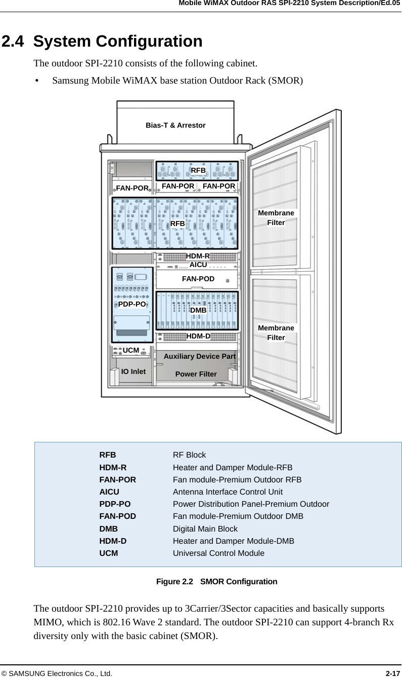
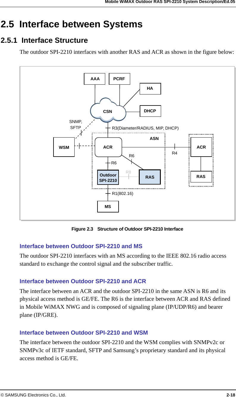
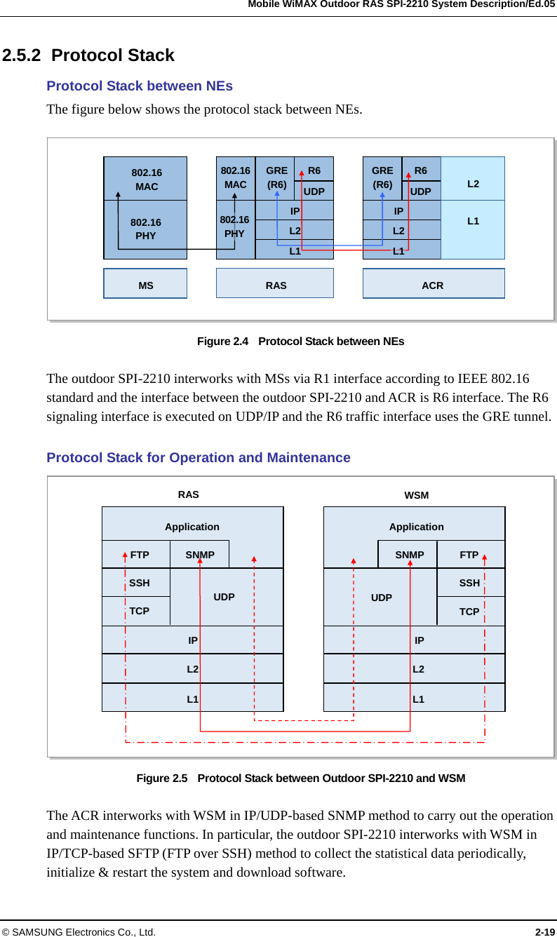
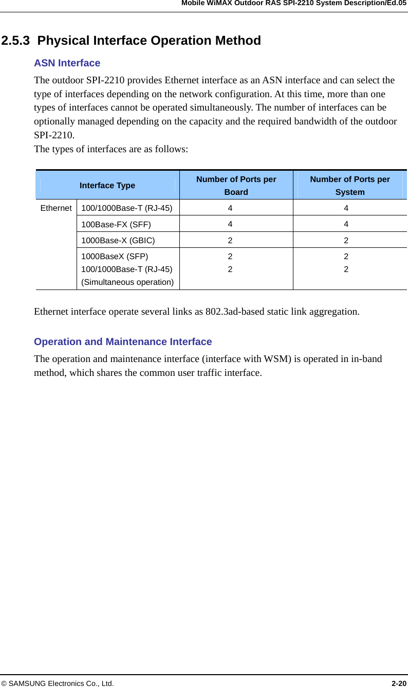
Discussion / Help
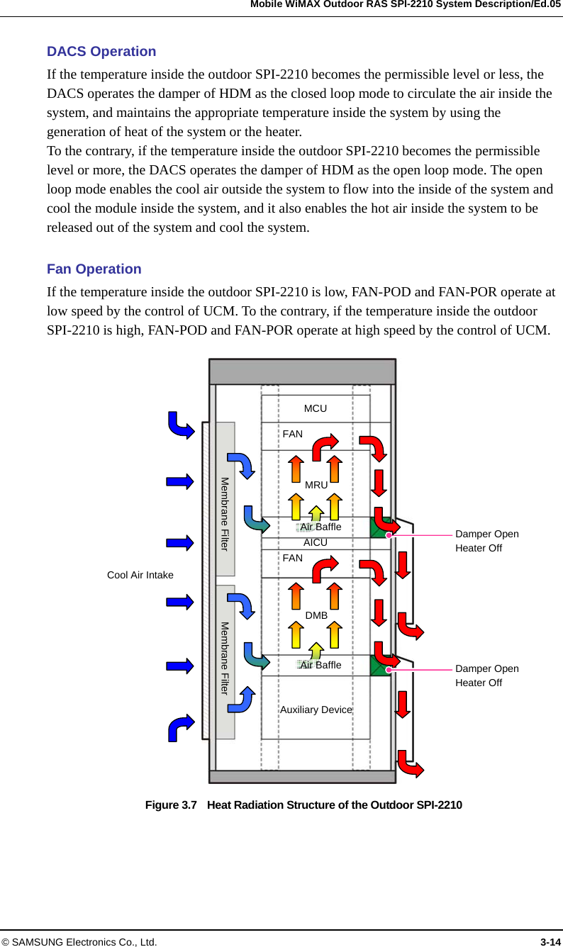
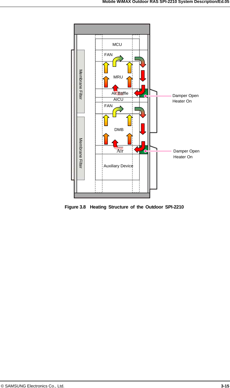
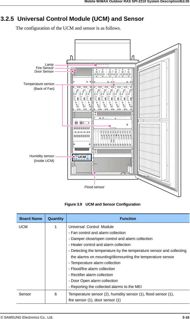
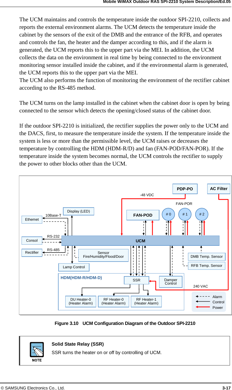
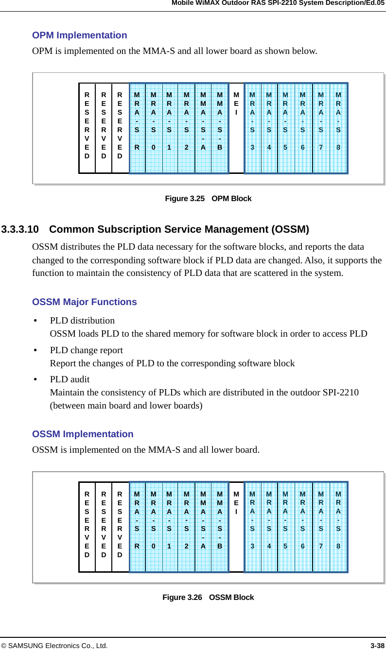
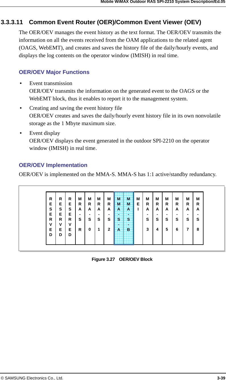
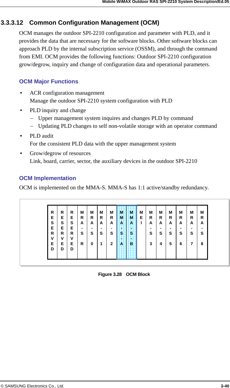
Navigation


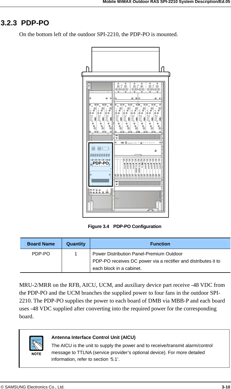
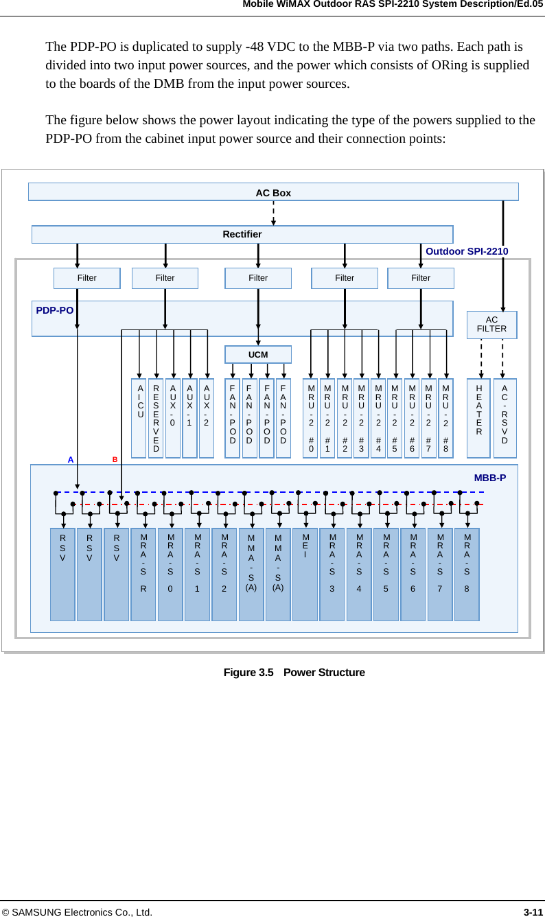
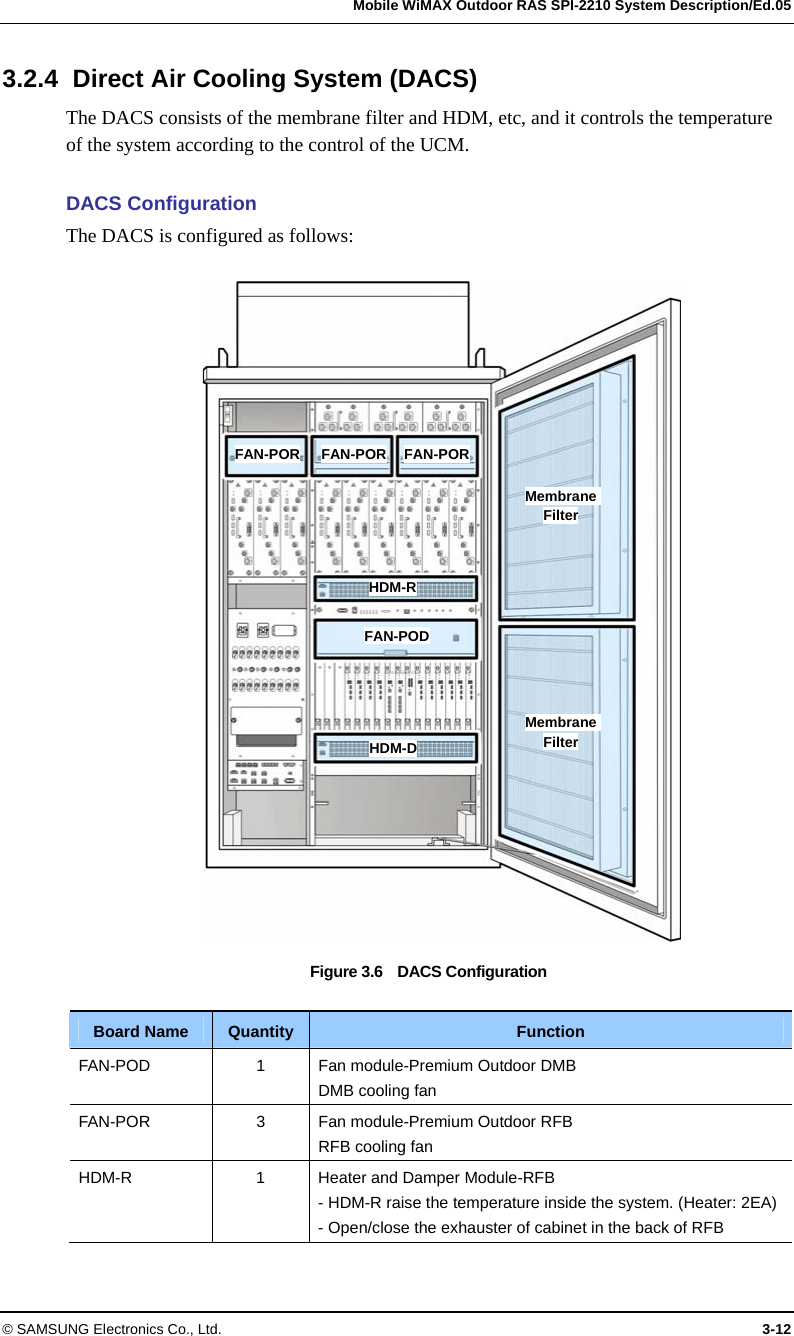
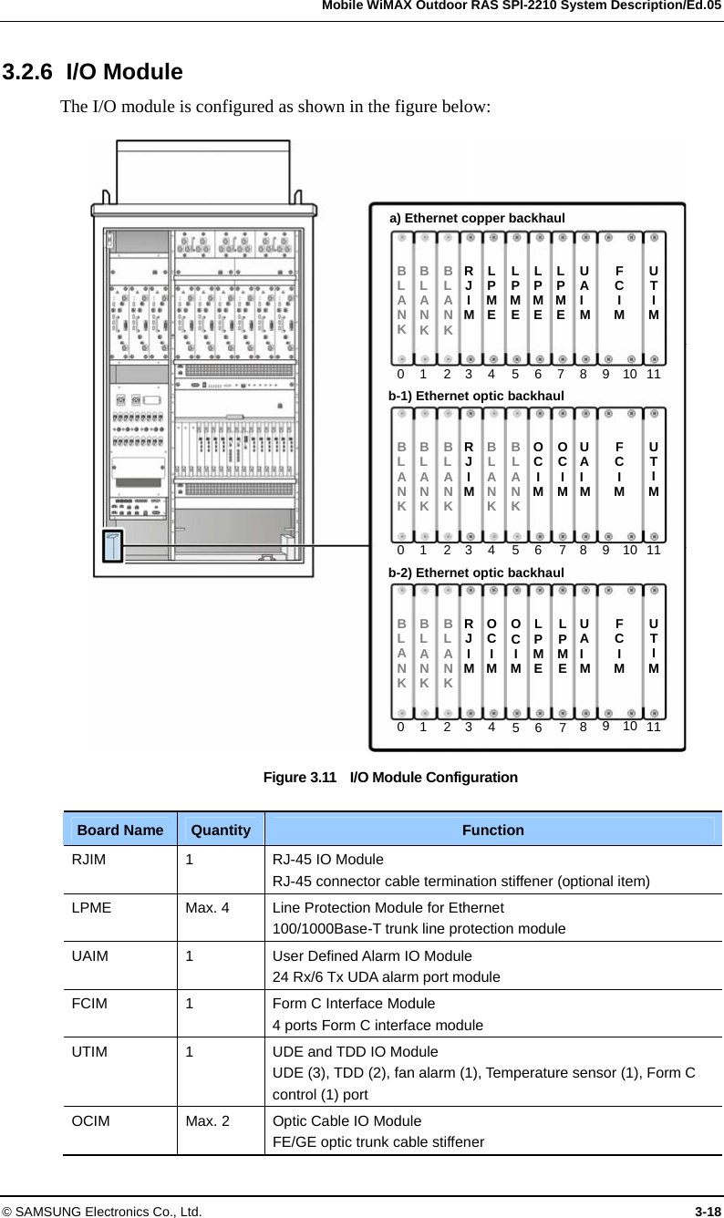
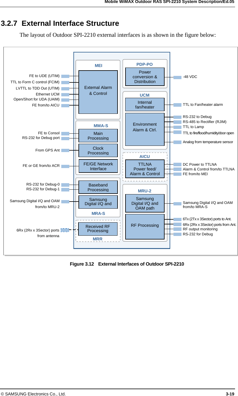
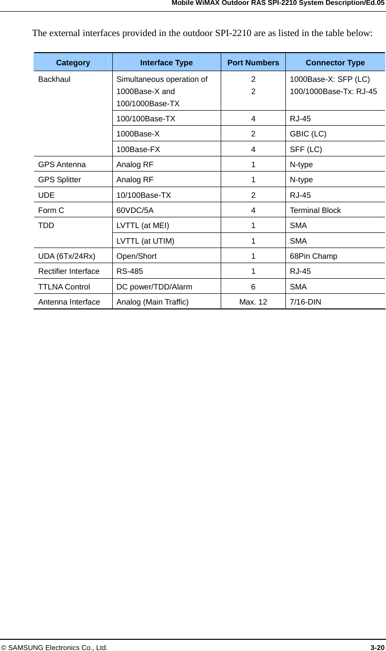
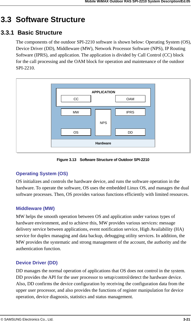
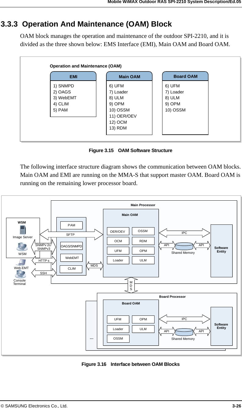
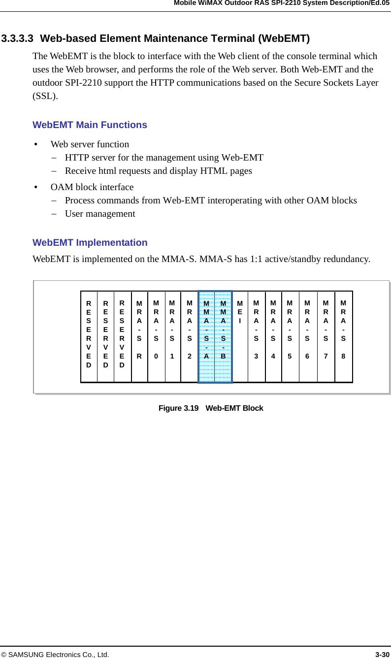
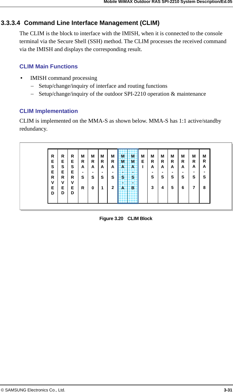
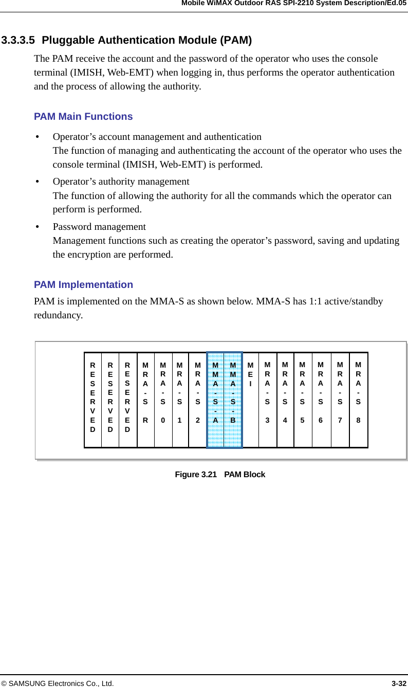
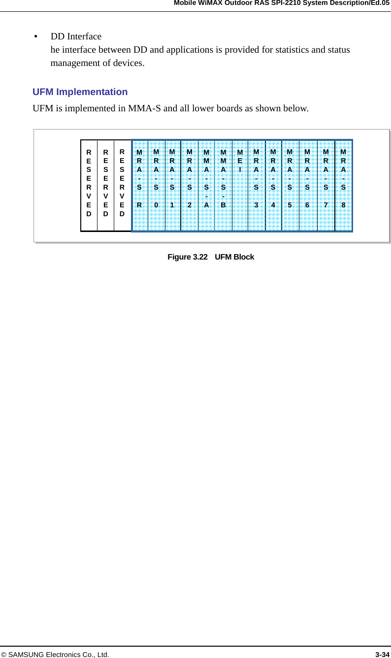
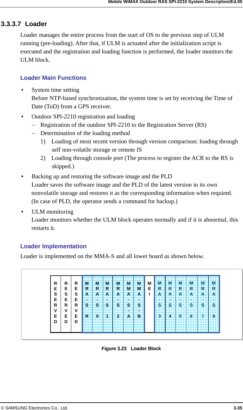
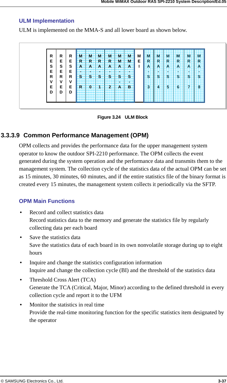
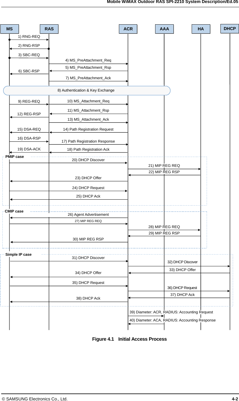
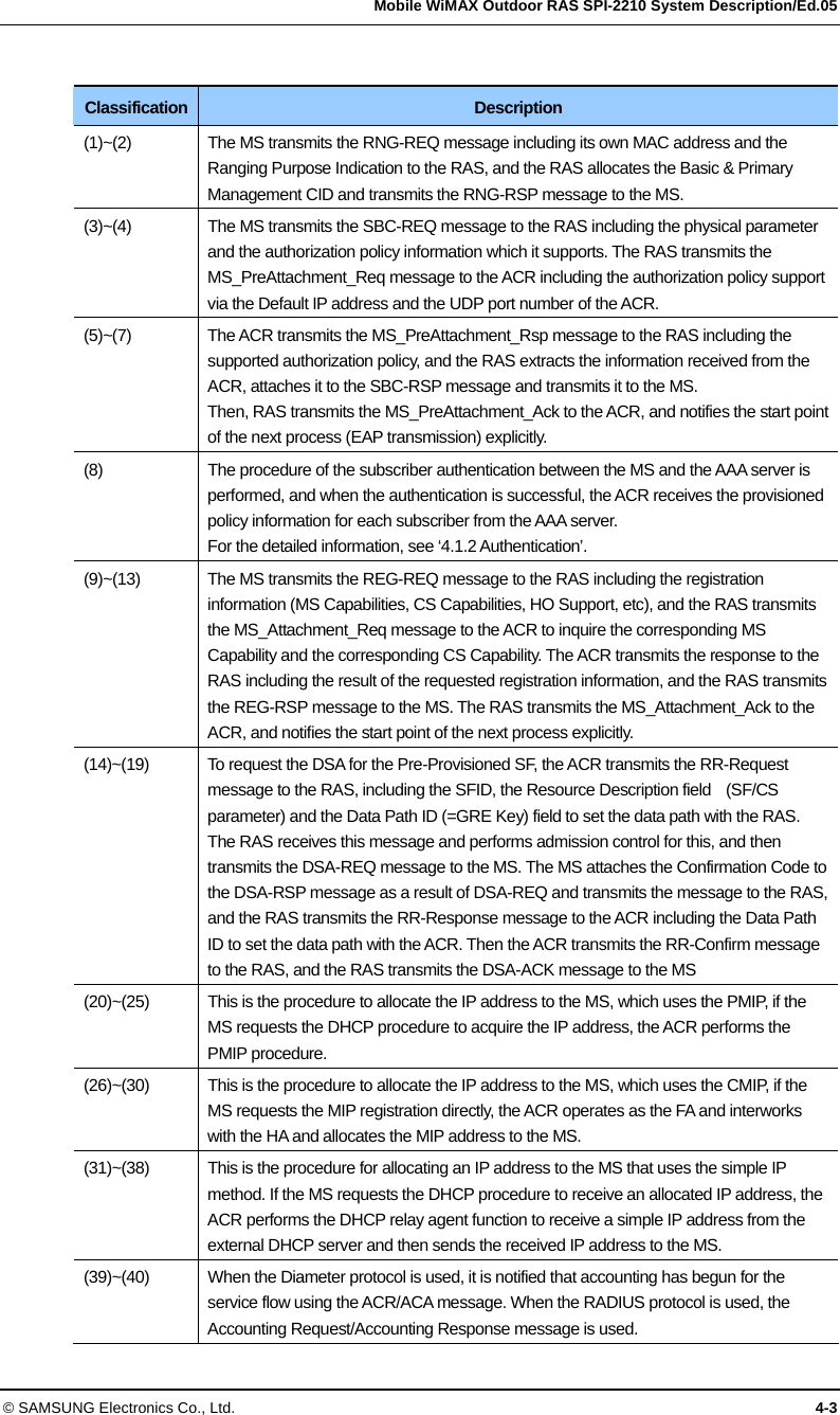
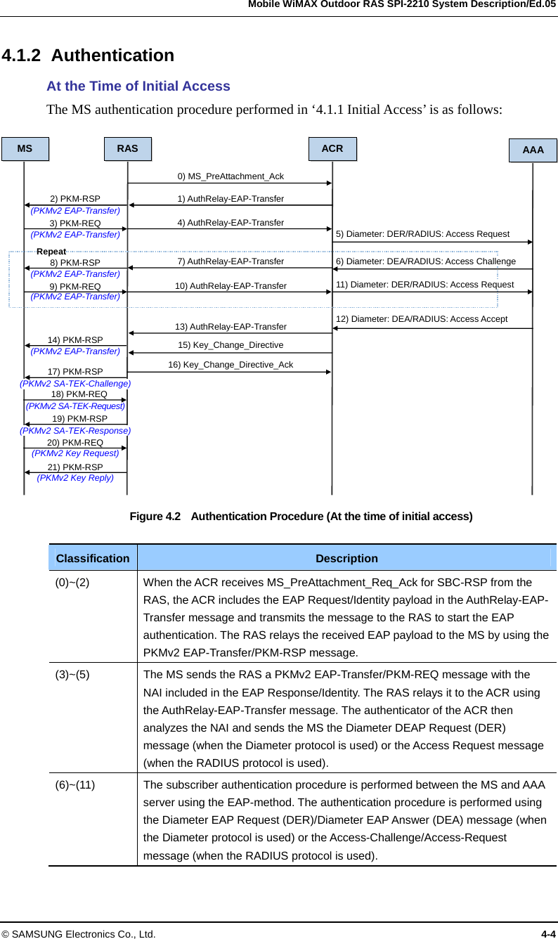
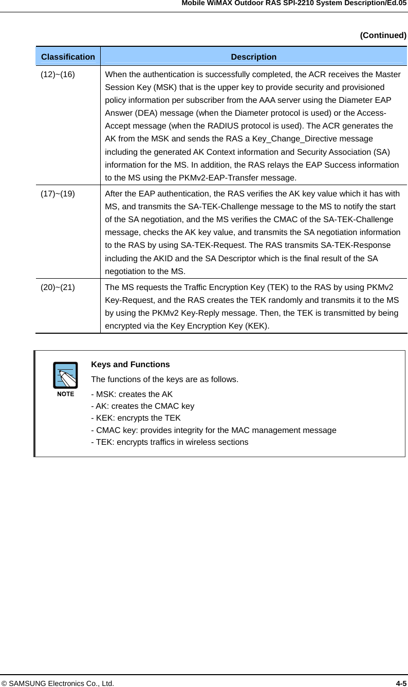
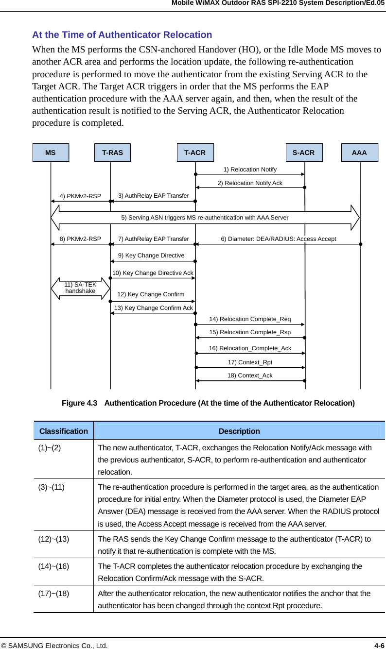
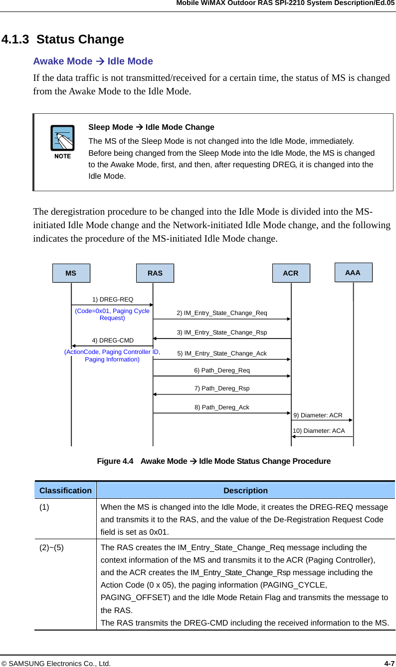
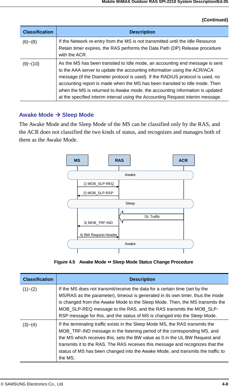
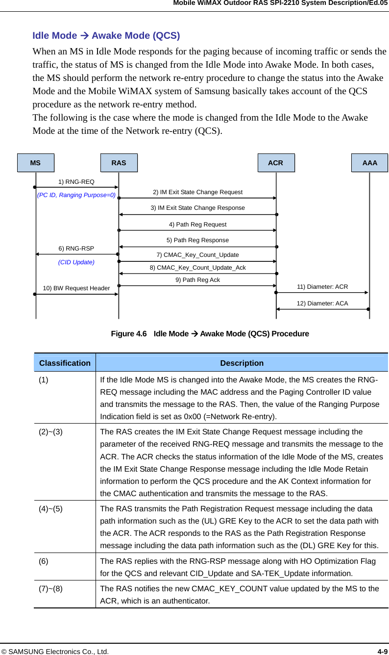
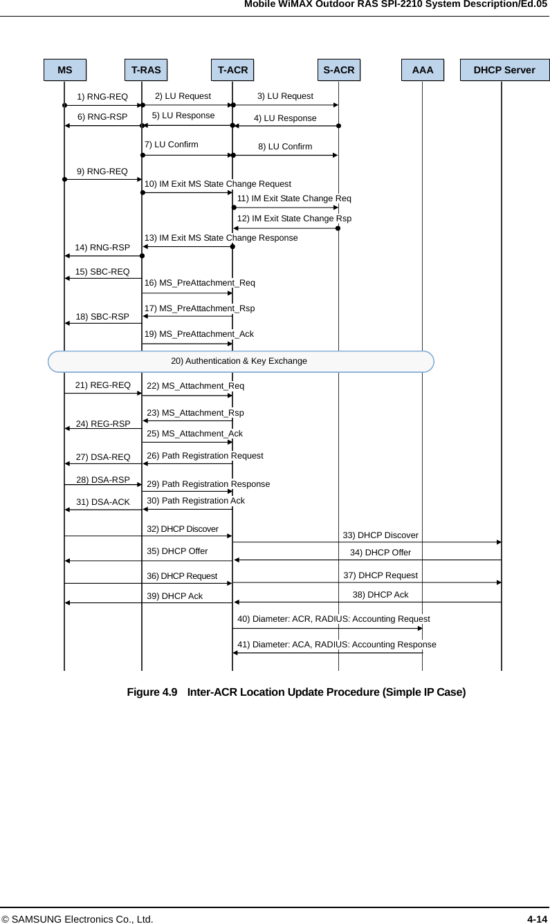
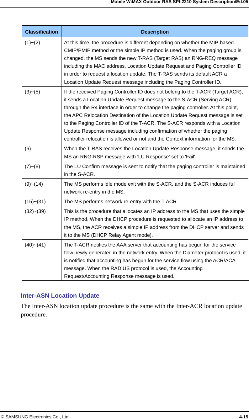
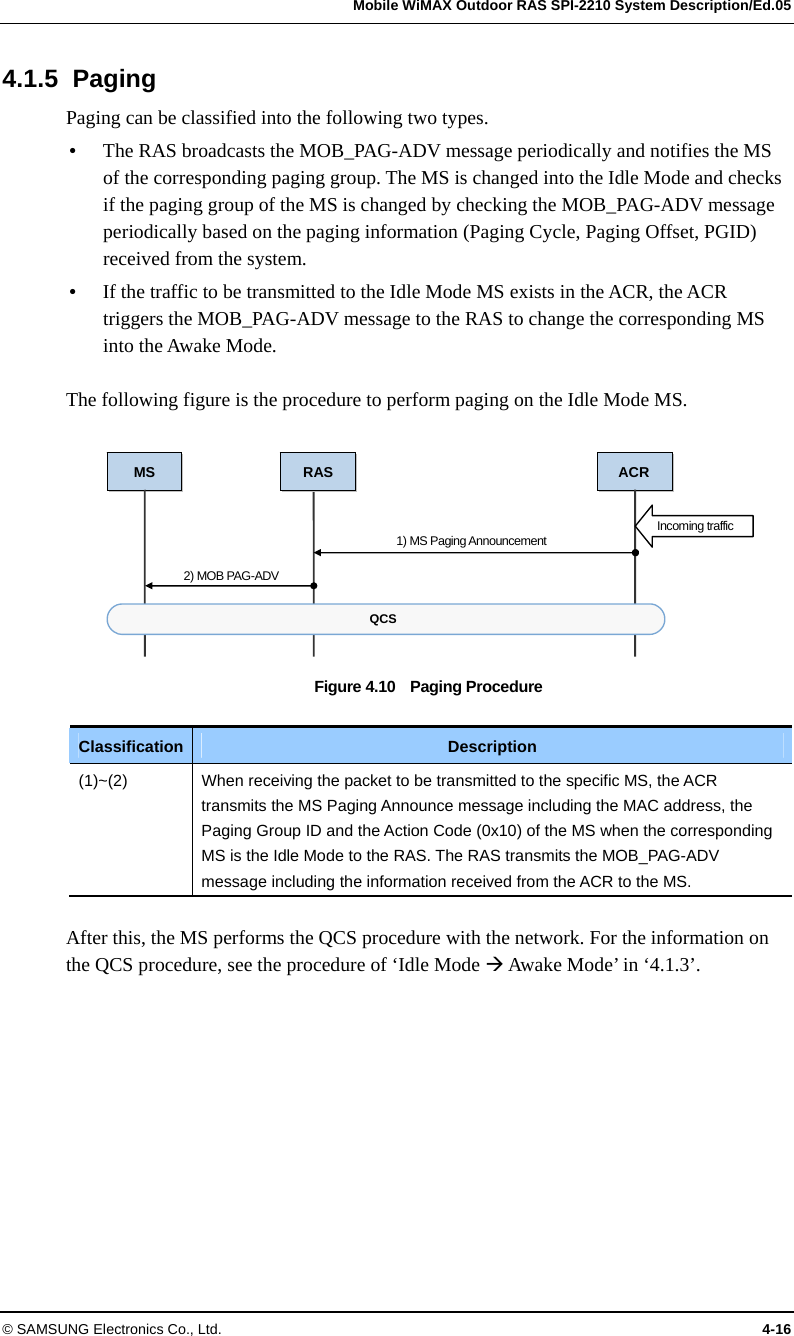
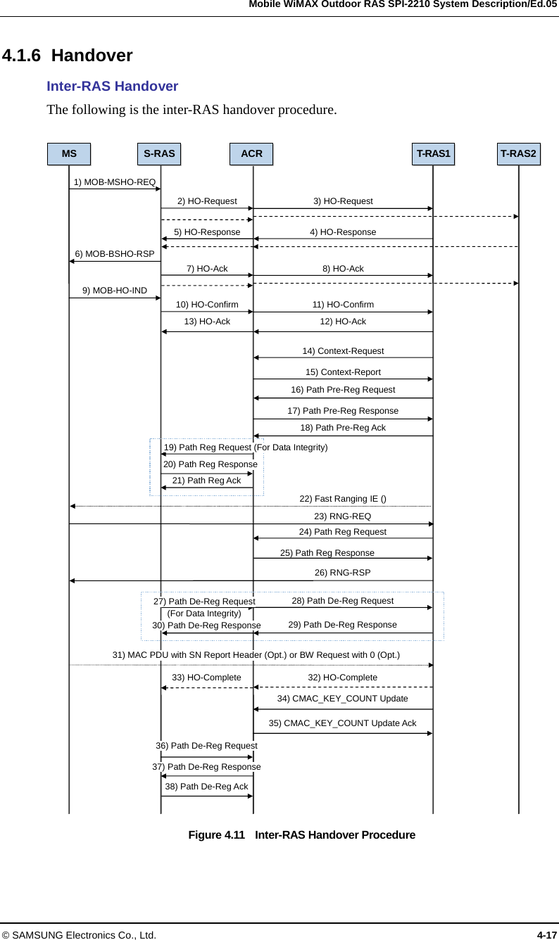
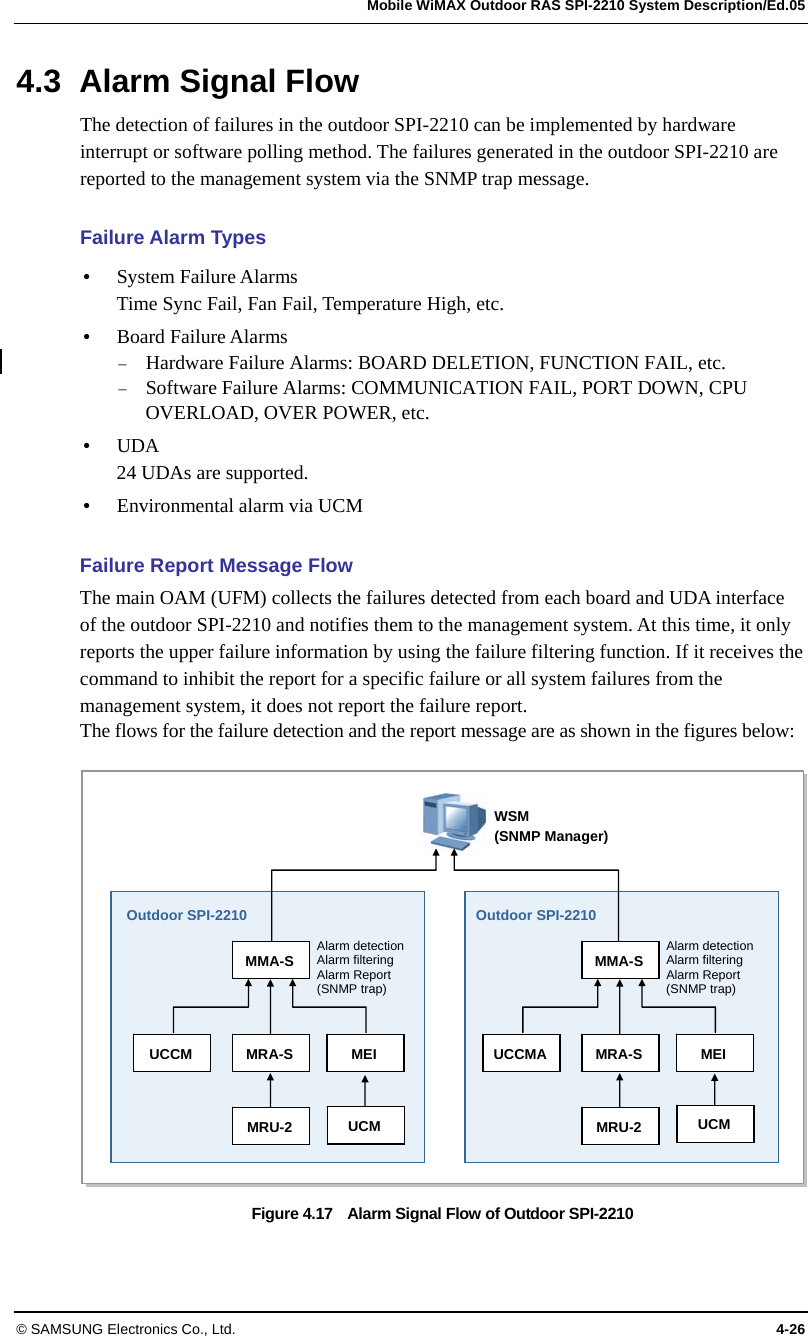
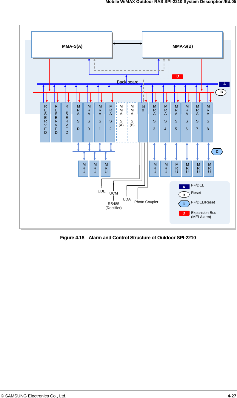
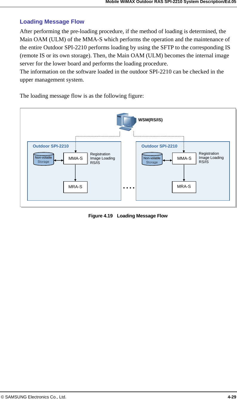
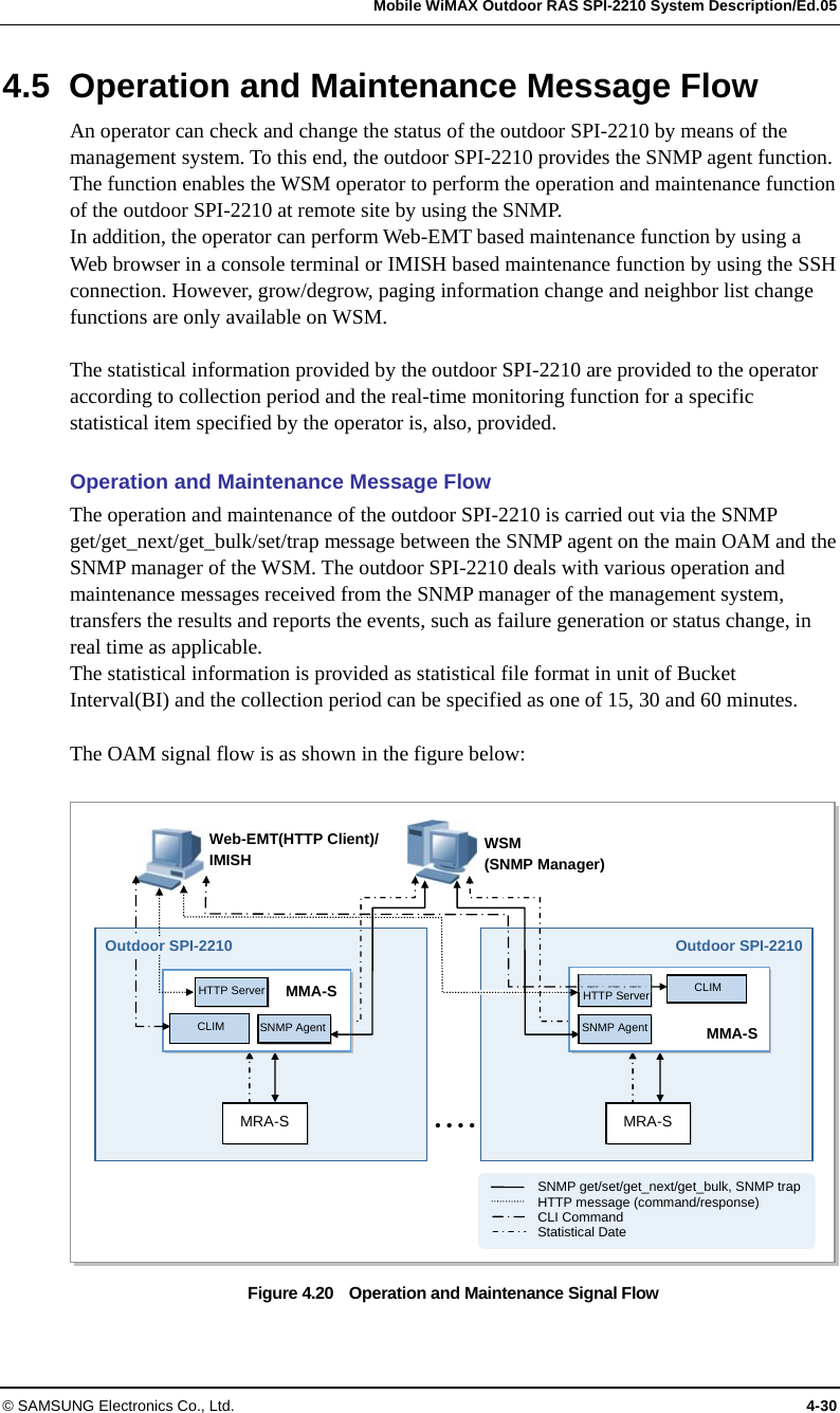
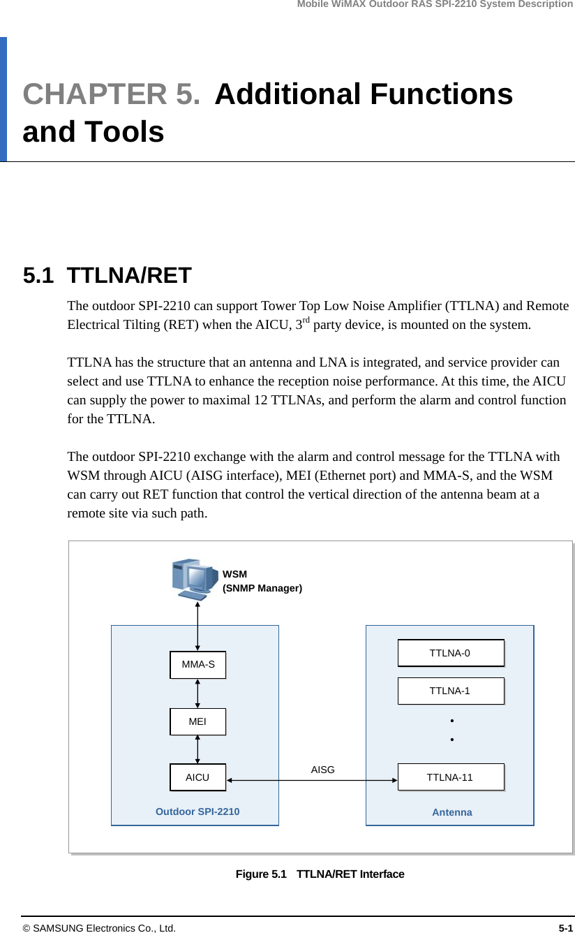
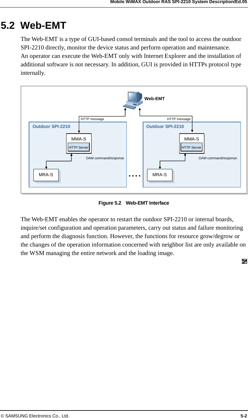
![Mobile WiMAX Outdoor RAS SPI-2210 System Description/Ed.05 © SAMSUNG Electronics Co., Ltd. 3-5 Mobile WiMAX base station Main control board Assembly-Standard (MMA-S) The MMA-S carries out the main processor function and the GPS reception function. The MMA-S has the redundancy configuration for reliability. y Main Processor Function The MMA-S is the board that carries out the role as the highest layer in the outdoor SPI-2210 and is equipped with the main processor. The main processor of the MMA-S performs the functions, such as communication path setting between MS and ACR, Ethernet switch function in the outdoor SPI-2210, system operation and maintenance and TDD signal control. The MMA-S manages the status of all hardware and software in the outdoor SPI-2210 and reports each status information to WSM via ACR. In addition, the MMA-S allocates and manages the resources of the outdoor SPI-2210 and the connection of the MMA-S and a PC for the Web-EMT enables to maintain the outdoor SPI-2210 with no interworking with ACR. The MMA-S has the redundancy configuration of active/standby to allow the standby MMA-S to replace the function of the active MMA-S when a fault occurs in the active MMA-S. y GPS Reception and Clock Distribution Function The MMA-S is equipped with Universal Core Clock Module (UCCM) for GPS reception. The UCCM enables each block of the outdoor SPI-2210 to be operated in the synchronized clock system. The UCCM mounted on the MMA-S creates the system clocks [56 MHz, 12.5 Hz (80 msec), PP2S, analog 10 MHz, 61.44 MHz] by using the reference signal received from a GPS and distributes them to the hardware blocks in the system. These clocks are used to maintain the internal synchronization of the outdoor SPI-2210 and operate the system. If no GPS signal is received due to a fault, the UCCM carries out the holdover function to provide the normal clock for a certain time as provided in the existing system. In addition, if a fault occurs in the UCCM of the active MMA-S, the redundancy status between the UCCMs of the active MMA-S and the standby MMA-S is switched and then the redundancy status between MMA-Ss is, also, switched immediately. y Network Interface Function The MMA-S interfaces with an ACR in Gigabit Ethernet or Fast Ethernet method. The MMA-S can provide maximum two Gigabit Ethernet ports or four Fast Ethernet ports per board, and support the link aggregation redundancy method. The MMA-S can be divided as follows depending on the interface types provided by MMA-S, and the service provider can choose the interface type. − MMA-SC: Four 100/1000Base-T Copper ports − MMA-SF: Four 100Base-FX Small Form factor Fixed (SFF) ports − MMA-SM: Two 100/1000Base-T ports and two 1000Base-X Small Form factor Pluggable (SFP) ports − MMA-SG: Two 1000Base-X Gigabit Interface Converter (GBIC) ports](https://usermanual.wiki/Samsung-Electronics-Co/SPI-2210022502.user-manual/User-Guide-1247608-Page-46.png)