Samsung Electronics Co SPI-2331022500 Mobile WiMAX Outdoor RAS User Manual ATT E
Samsung Electronics Co Ltd Mobile WiMAX Outdoor RAS ATT E
UserManual.wiki
>
Samsung Electronics Co
>
SPI 2331022500 User Manual
Users Manual
Navigation menu
Upload a User Manual
Namespaces
Wiki Guide
HTML
PDF
Info
Views
User Manual
Discussion / Help
Navigation


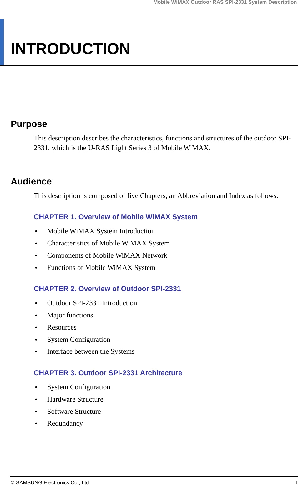
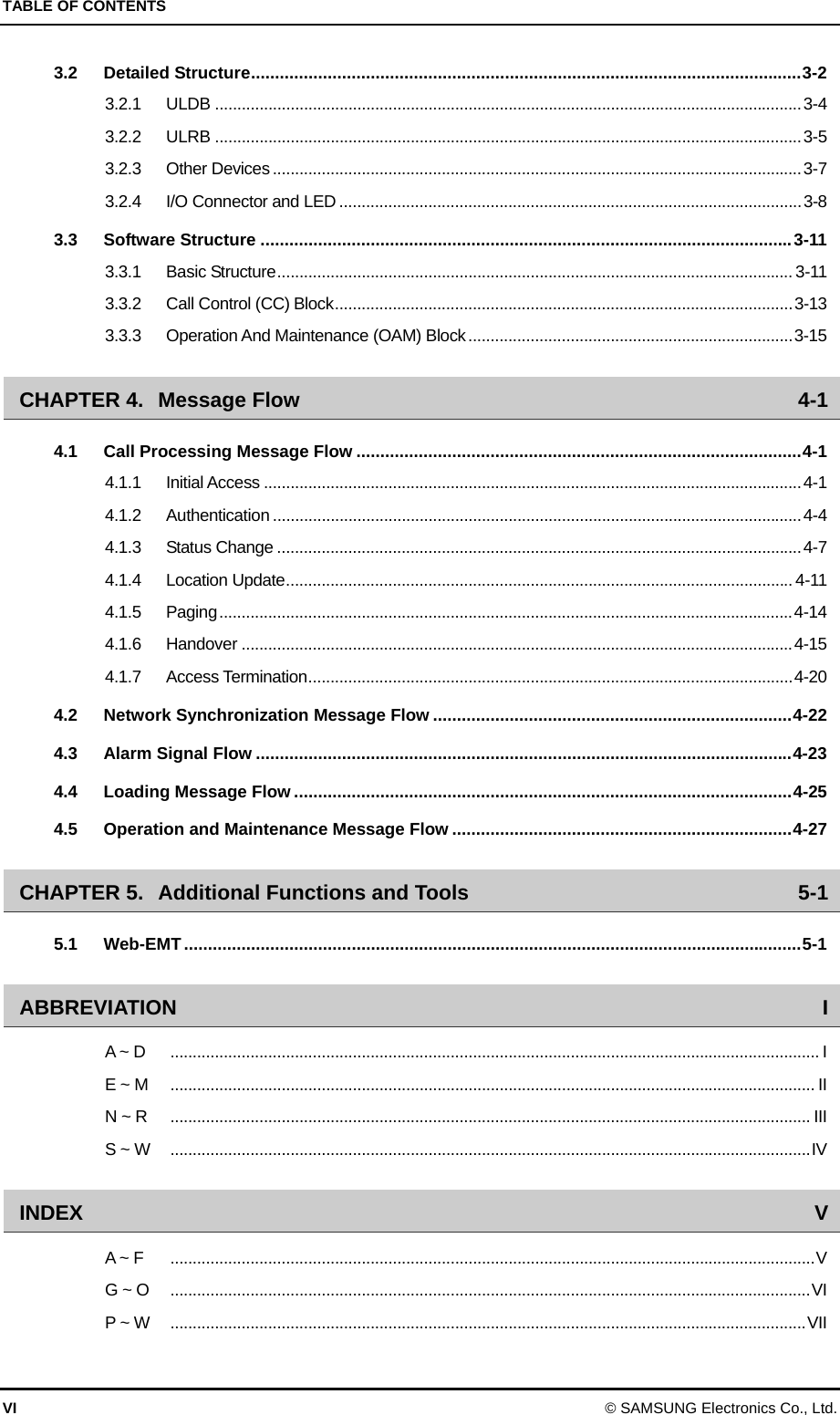
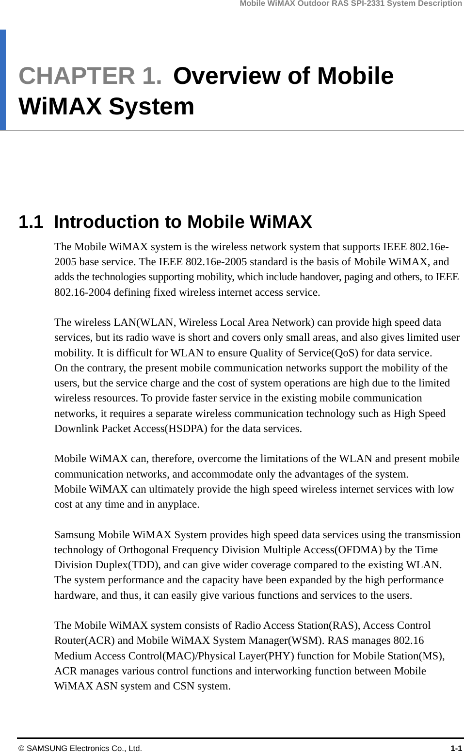
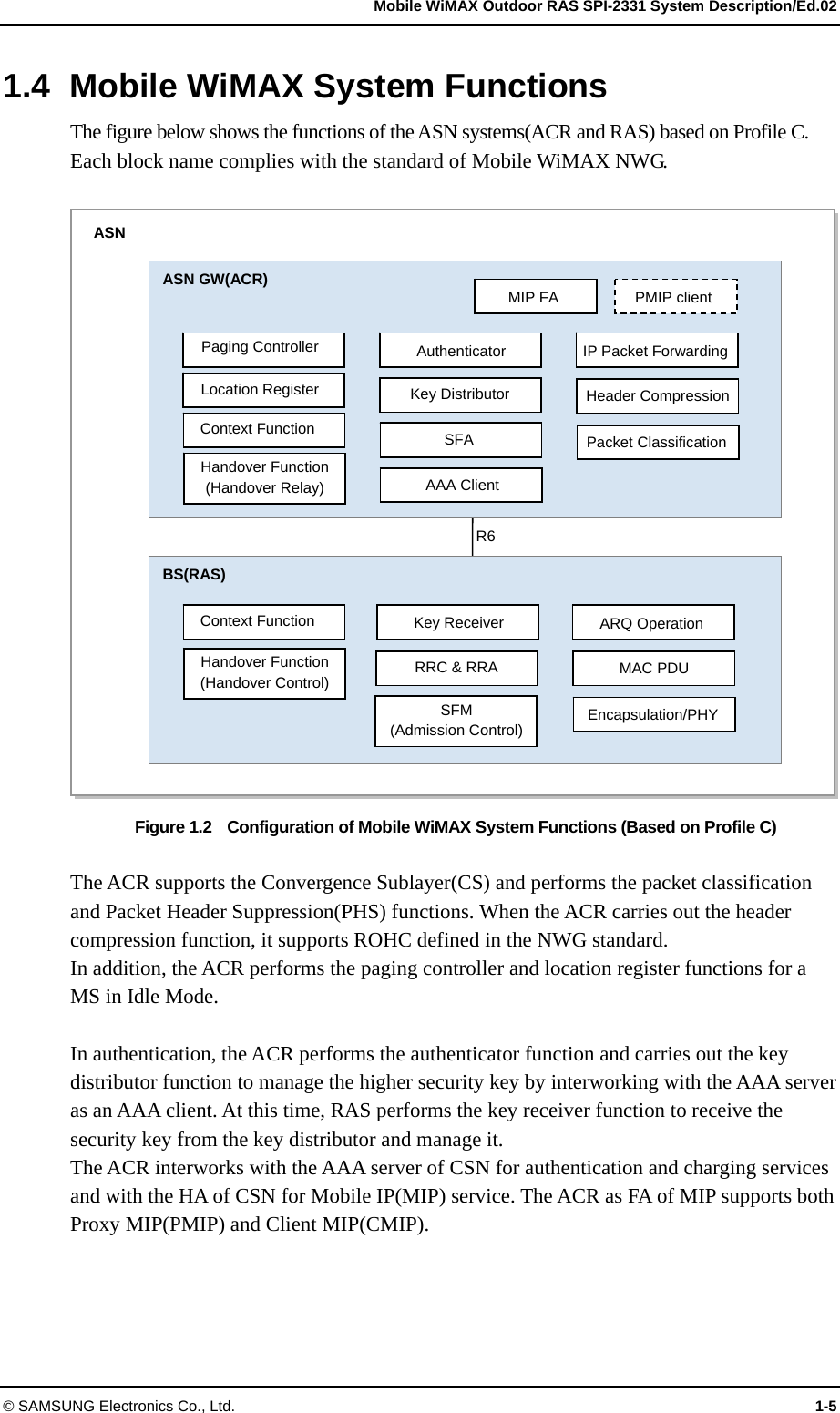
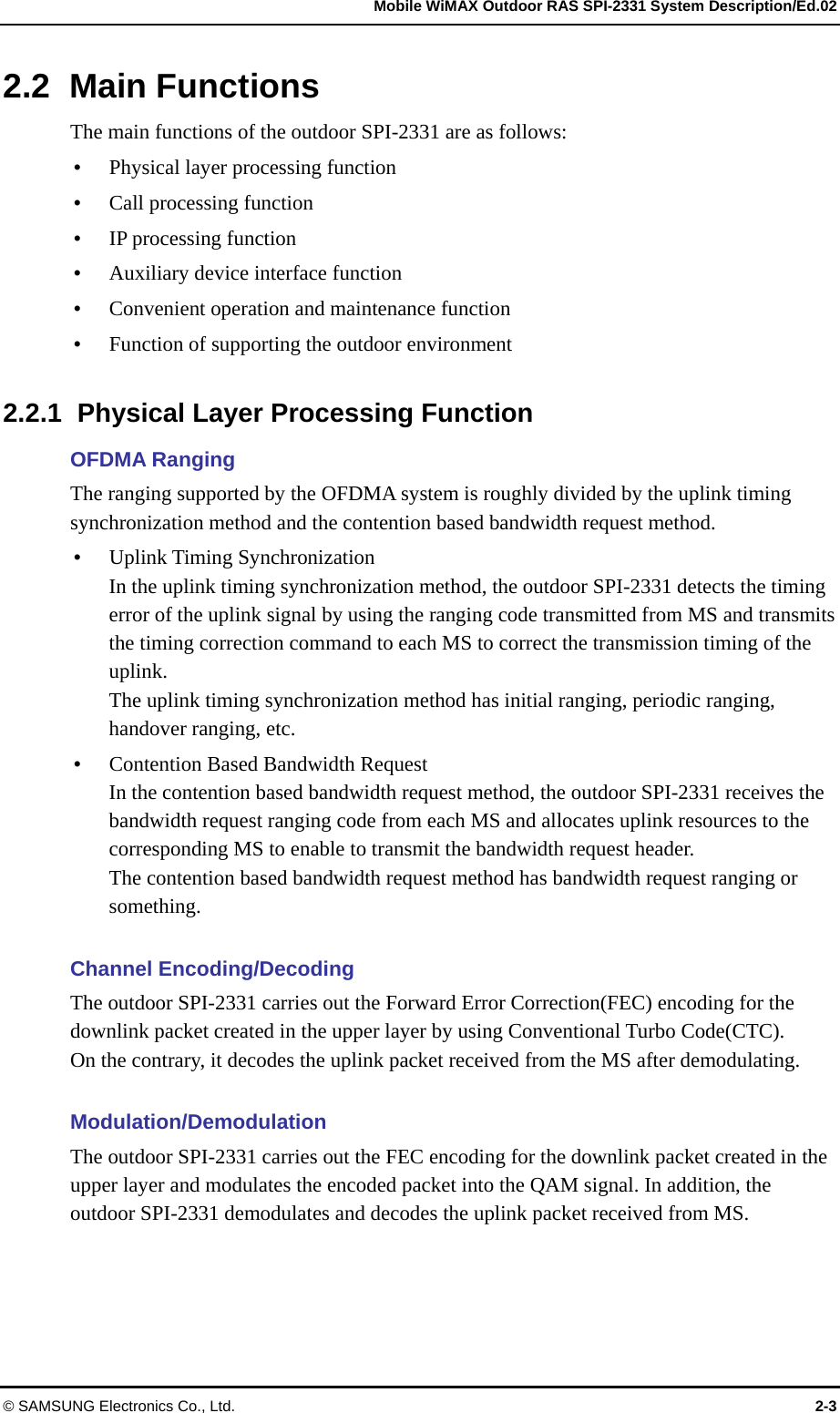
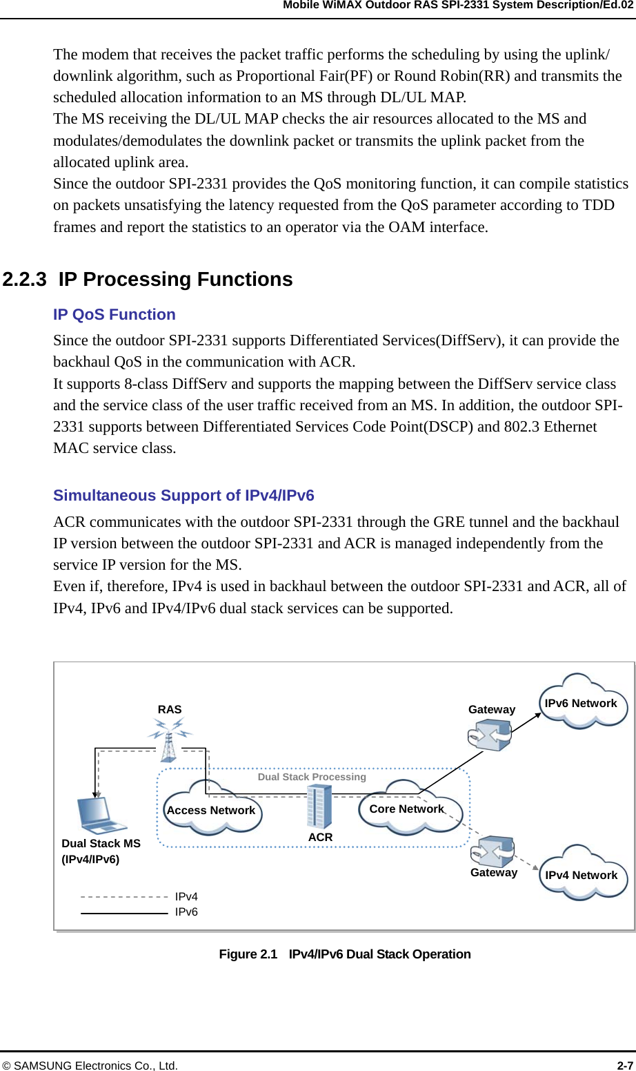
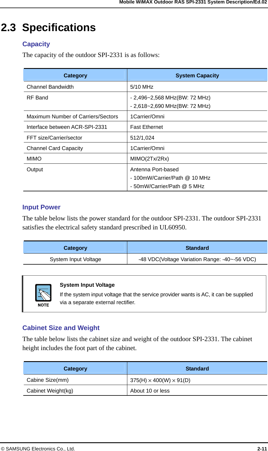
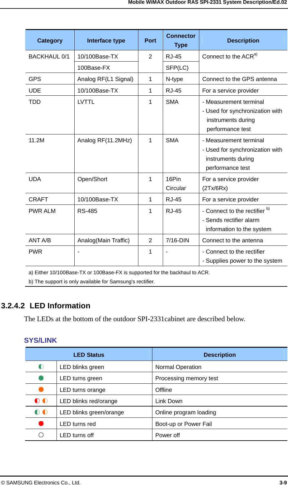
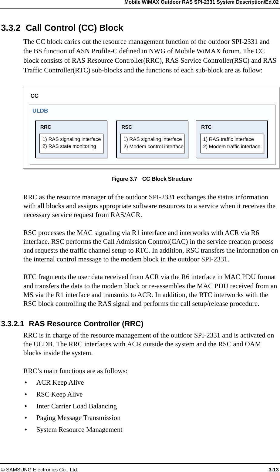
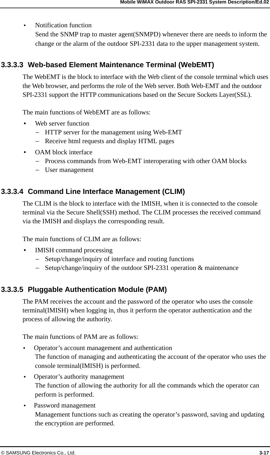
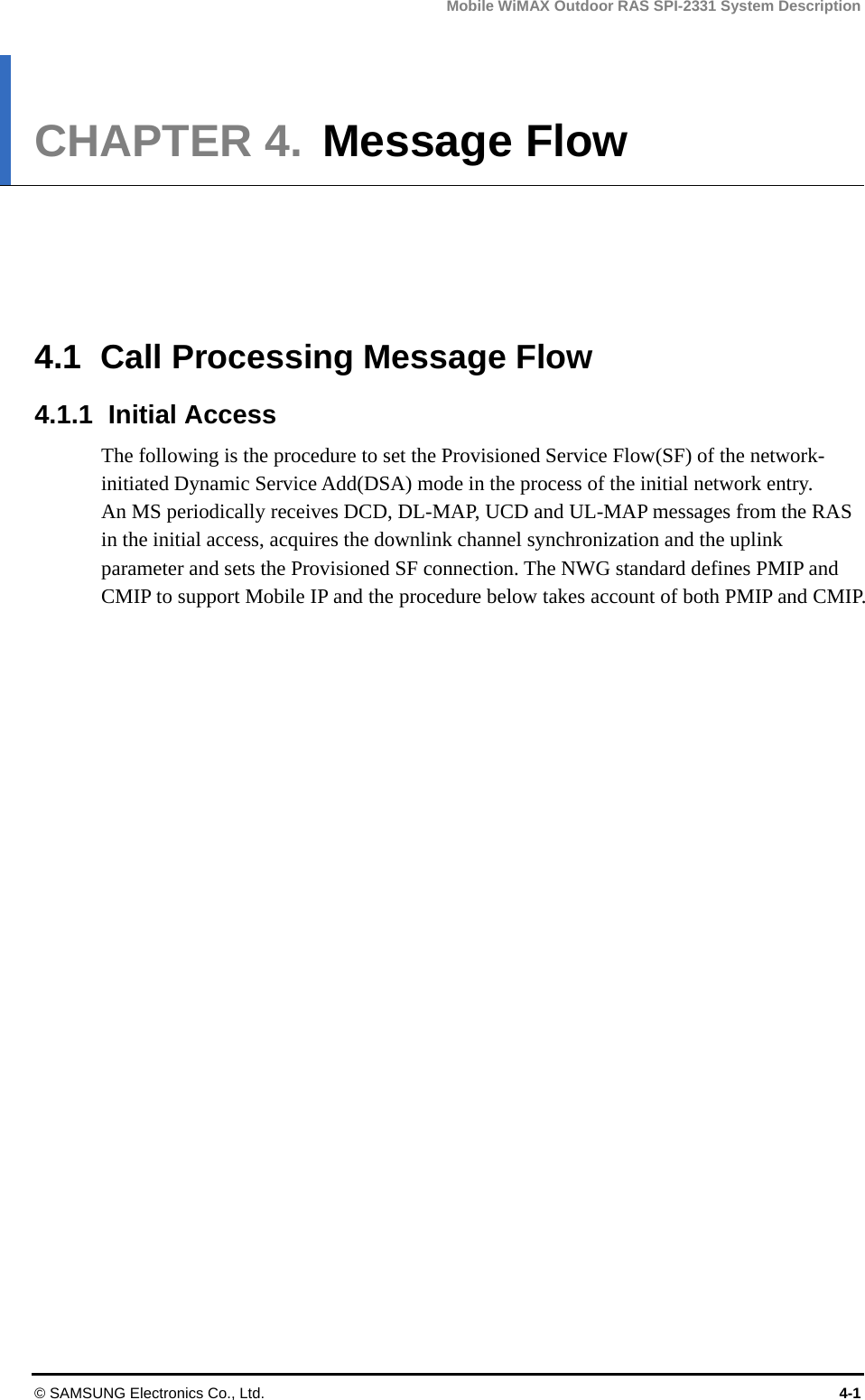
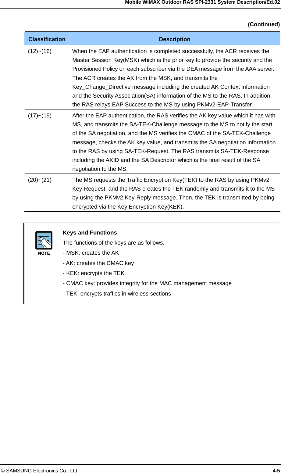
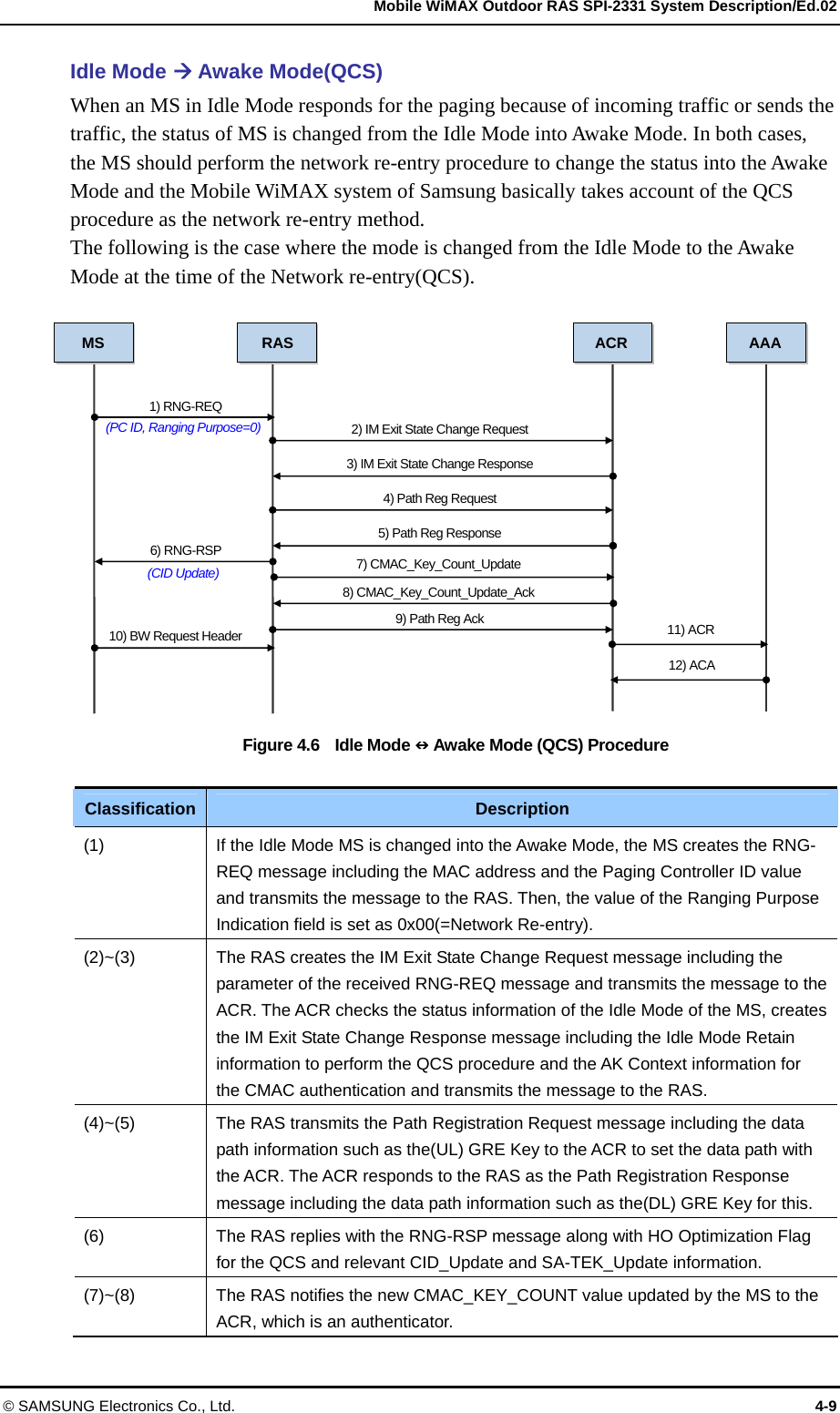
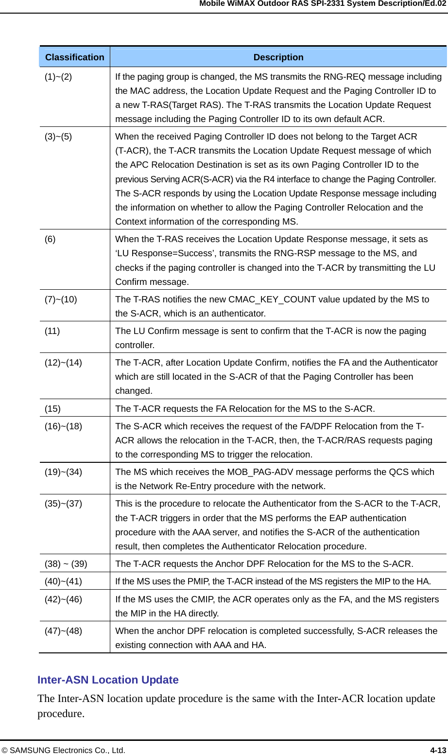
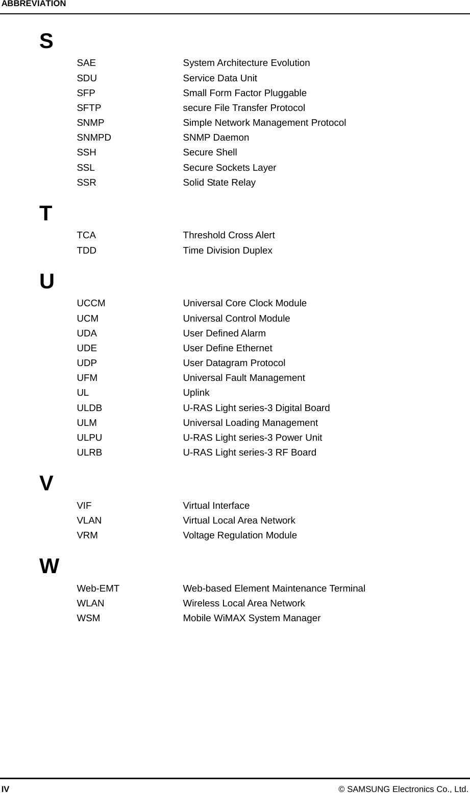
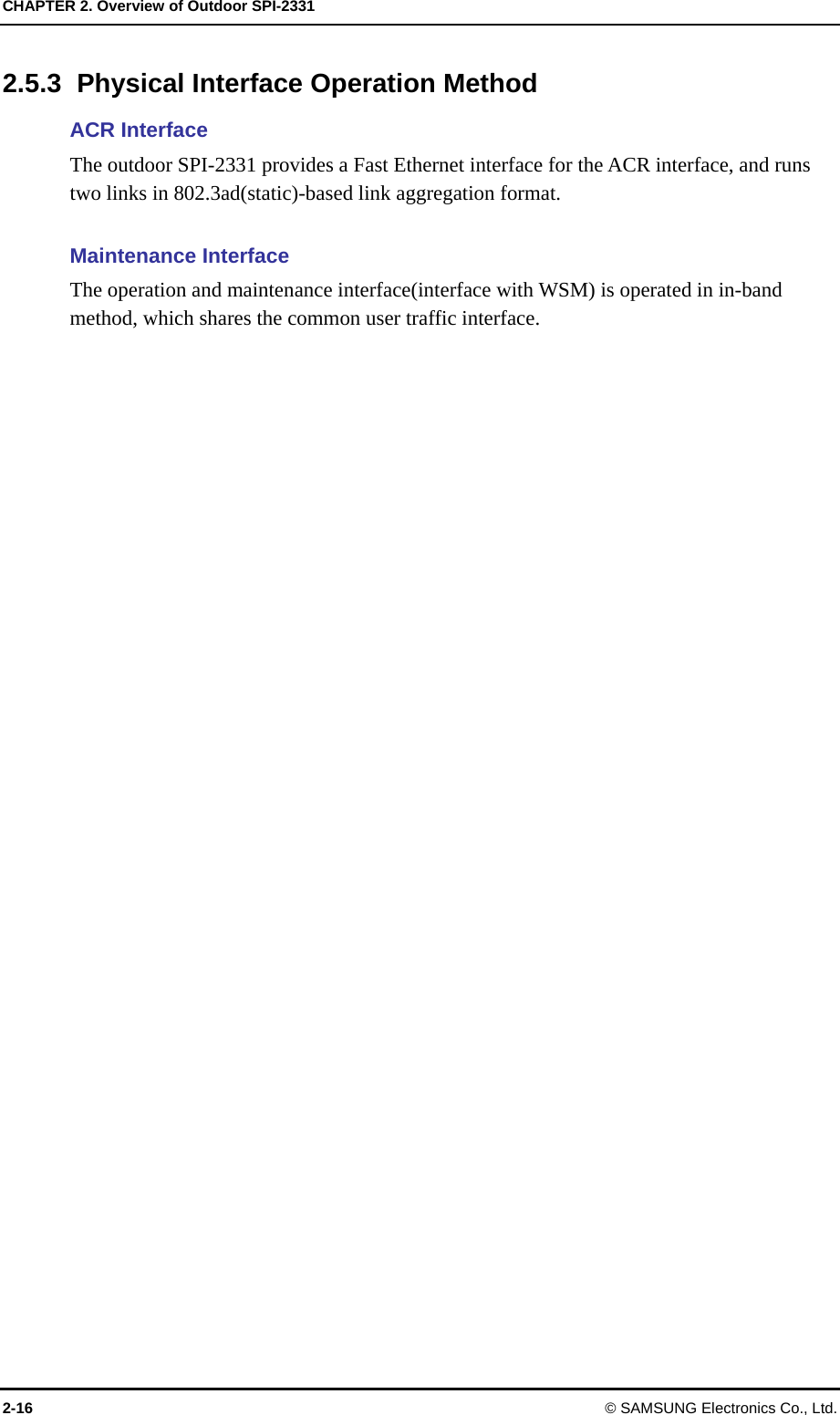
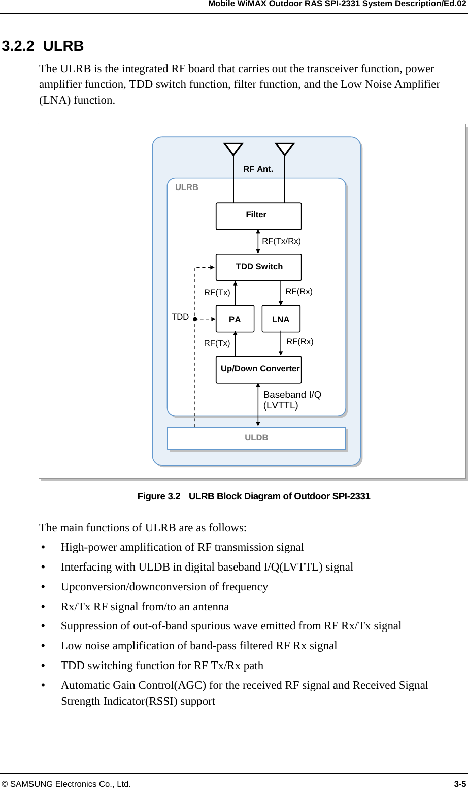
![Mobile WiMAX Outdoor RAS SPI-2331 System Description/Ed.02 © SAMSUNG Electronics Co., Ltd. 2-13 2.4 System Configuration The outdoor SPI-2331 consists of the following cabinet.y Samsung Mobile WiMAX base station Outdoor Rack(ULOE) Figure 2.2 ULOE Configuration The outdoor SPI-2331 provides up to 1Carrier/Omni capacities and basically supports MIMO, which is 802.16e Wave 2 standard. [Exterior of ULOE] [Front] [Back] ULRB H e a t e r ULPU UCCM ULDB ULPM-2FE [Interior of ULOE]](https://usermanual.wiki/Samsung-Electronics-Co/SPI-2331022500/User-Guide-910633-Page-30.png)
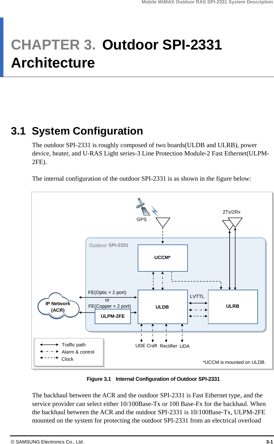
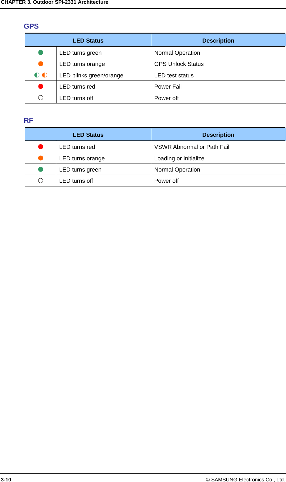
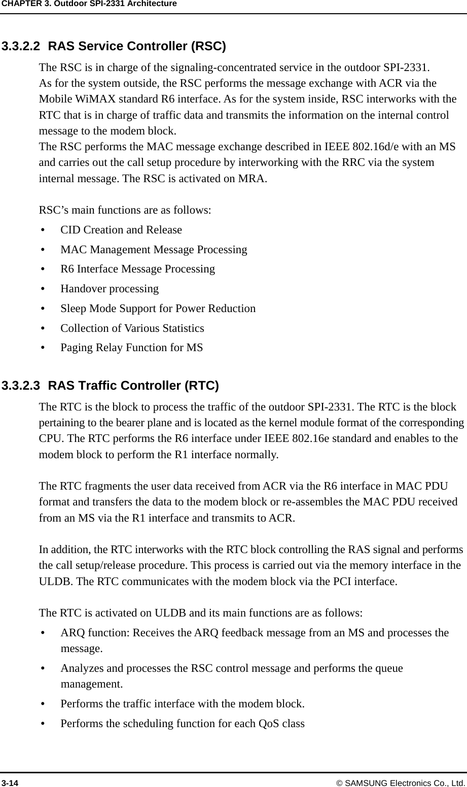
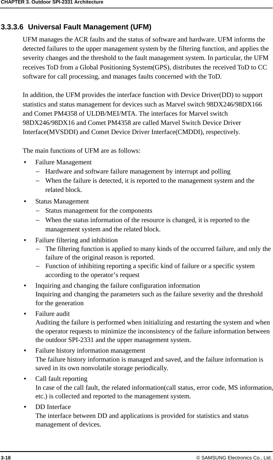
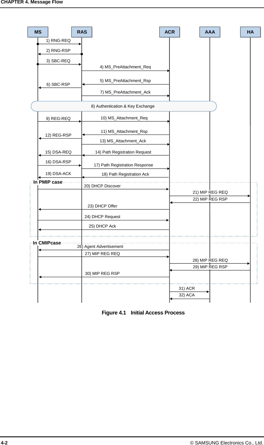
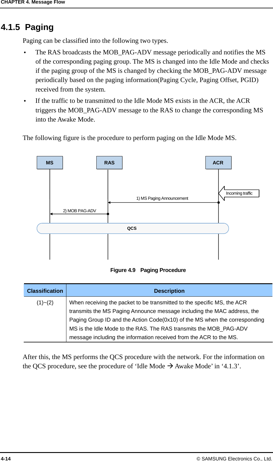
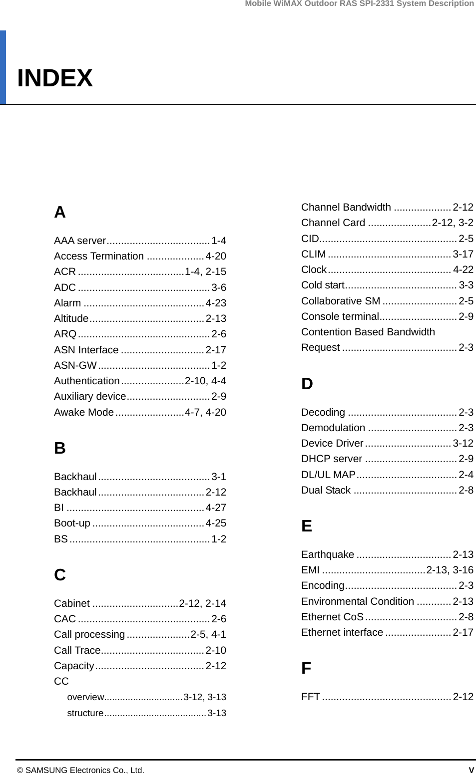
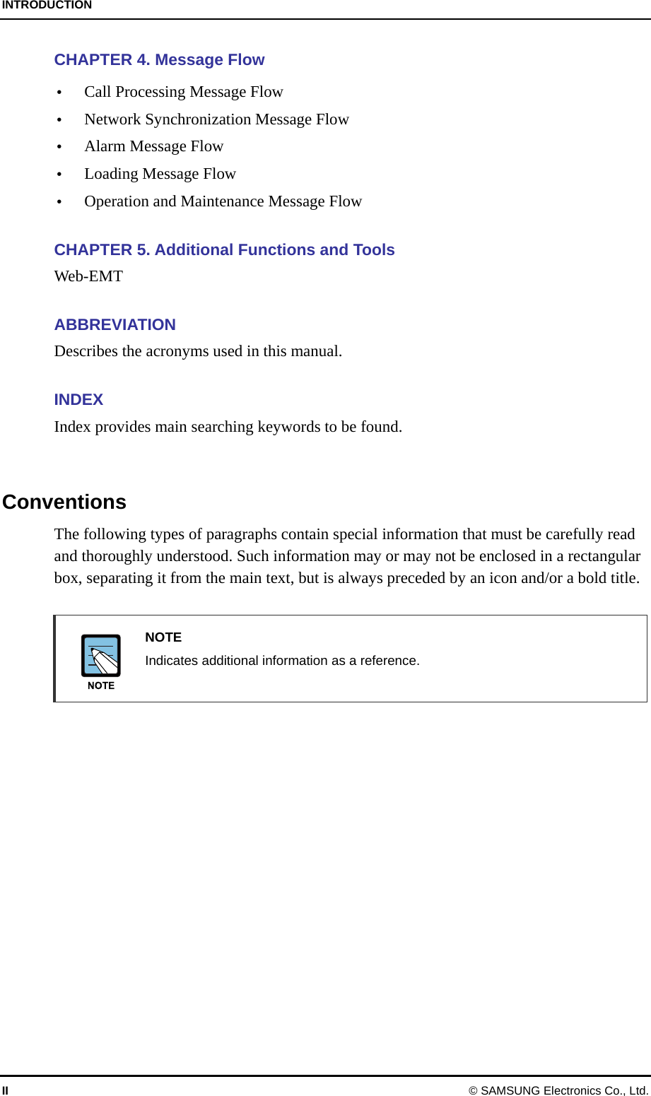
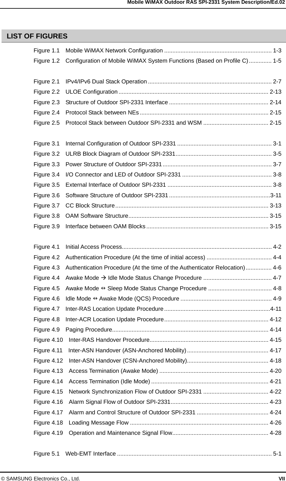
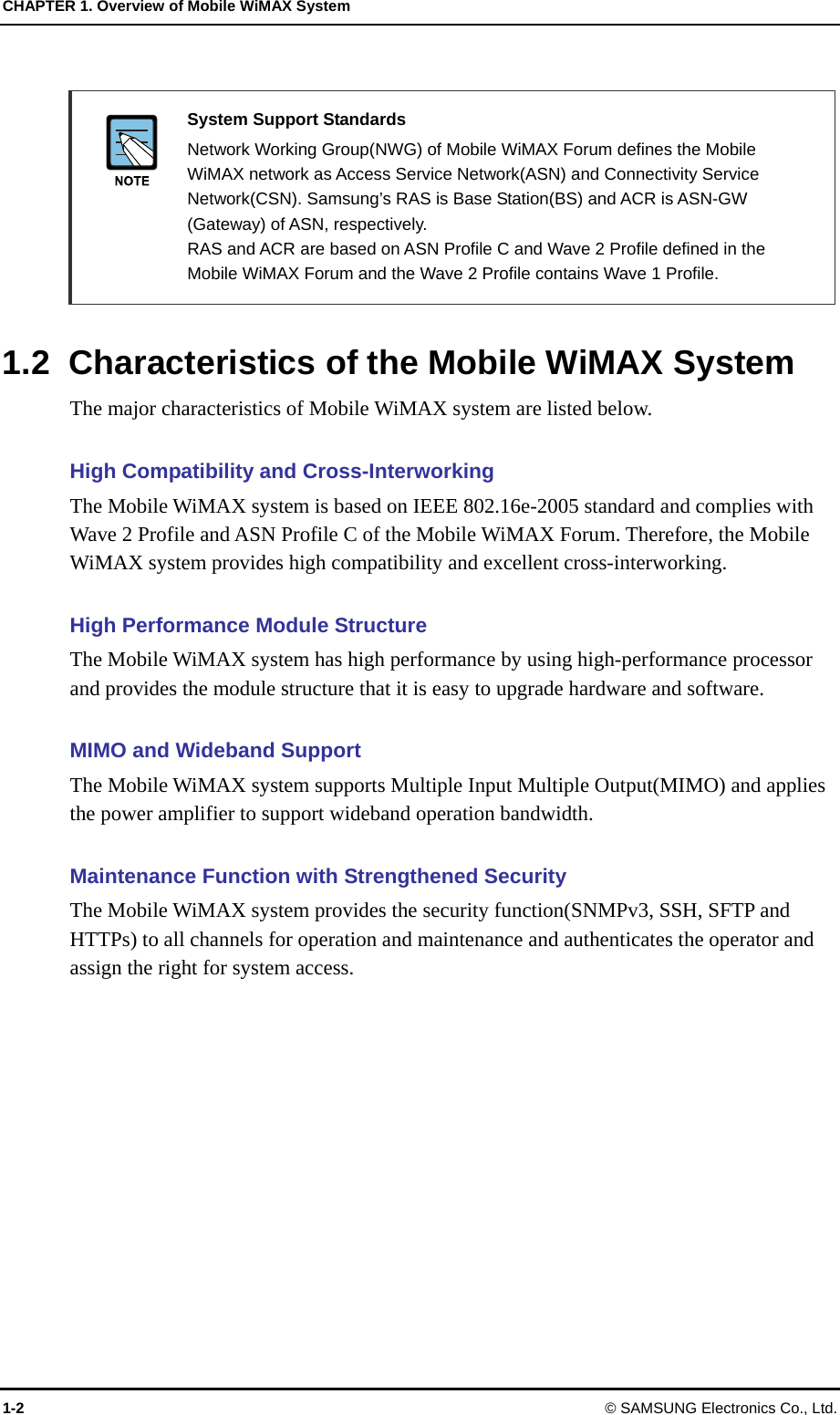
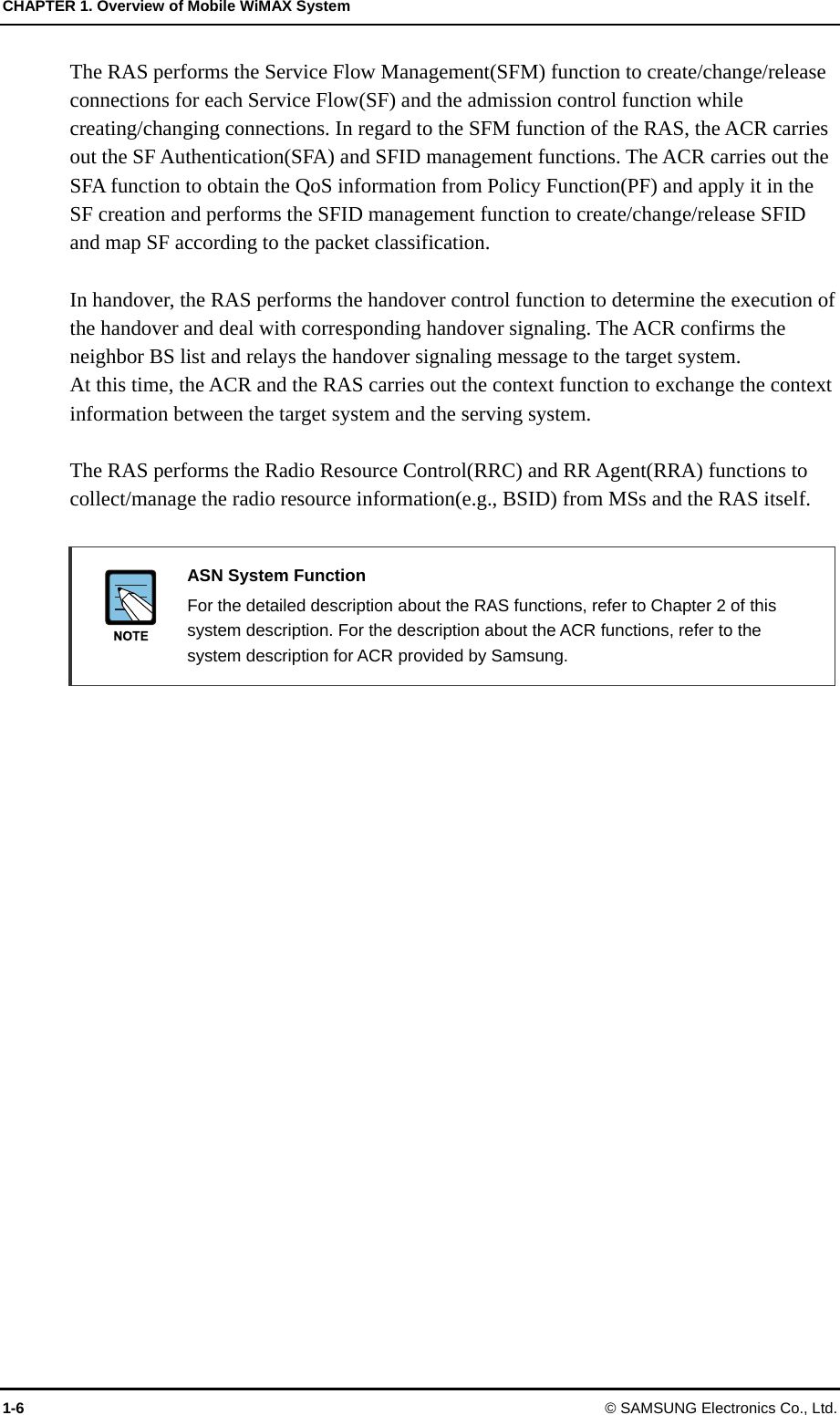
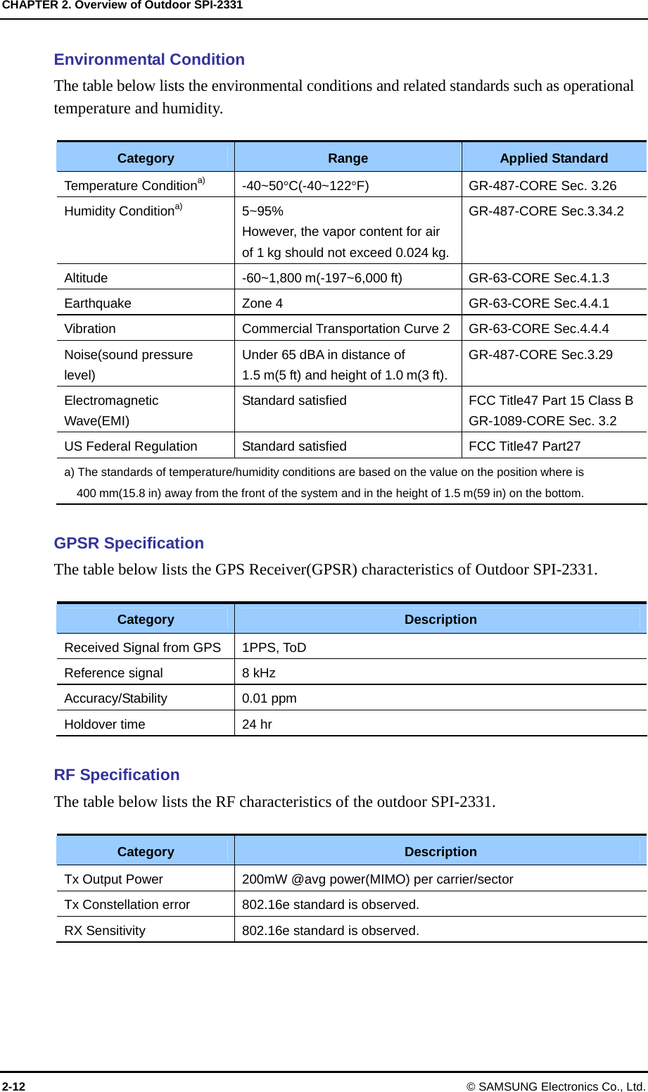
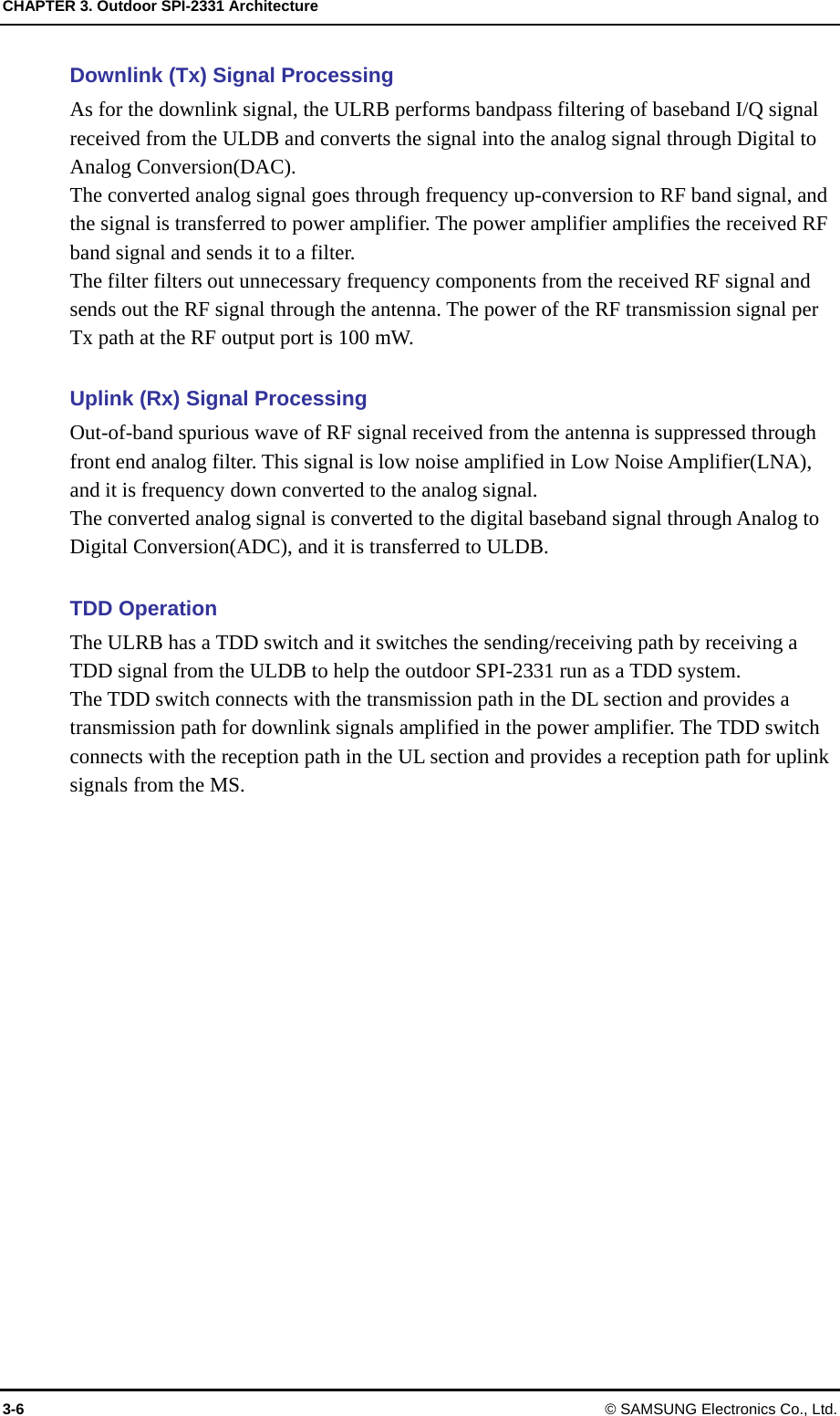
![CHAPTER 3. Outdoor SPI-2331 Architecture 3-4 © SAMSUNG Electronics Co., Ltd. 3.2.1 ULDB The ULDB is the uppermost board in the outdoor SPI-2331. The main processor of the outdoor SPI-2331 is installed on this board and it provides system operation and a maintenance function. In addition, the ULDB is an integrated digital board providing a modem, GPS signal receiving and clock distribution, and network interface functions. Main Processor Function The ULDB is the board that carries out the role as the highest layer in the outdoor SPI-2331 and is equipped with the main processor. The main processor of the ULDB performs the functions, such as communication path setting between MS and ACR, Ethernet switch function in the outdoor SPI-2331 and system operation and maintenance. The ULDB manages the status of all hardware and software in the outdoor SPI-2331 and reports each status information to WSM via ACR. In addition, the ULDB allocates and manages the resources of the outdoor SPI-2331 and the connection of the ULDB and a PC for the Web-EMT enables to maintain the outdoor SPI-2331 with no interworking with ACR. Modem Function The ULDB is equipped with the modem supporting IEEE 802.16e standard physical layer and the modem performs the OFDMA channel processing function. The ULDB modulates the packet data received, and transmits the modulated data to the ULRB as digital baseband I/Q(LVTTL) signal. In the contrary, the ULDB demodulated the data received from the ULRB, converts the data into the format defined in the IEEE 802.16e Mobile WiMAX physical layer standard and then transmits the converted data to the ACR via Ethernet interface. Network Interface Function The ULDB interfaces with an ACR in Fast Ethernet method and the ULDB can provide maximum two Fast Ethernet ports. Then the service provider can choose the copper or optic for the network interface. GPS Reception and Clock Distribution Function The Universal Core Clock Module(UCCM), which is installed as ULDB mezzanine, generates a system clock [Pulse Per 2 Second(PP2S), Reference Clock(44.8 MHz), Analog 11.2 MHz] by using the GPS signal from the GPS and distributes the clock to each board and module. Therefore, each device of the outdoor SPI-2331 runs under the synchronized clock system. The UCCM provides a holdover function(24-hour) which maintains its normal clock for a specific time period based on its prior learning capability when there is no GPS signal because of any accidents.](https://usermanual.wiki/Samsung-Electronics-Co/SPI-2331022500/User-Guide-910633-Page-37.png)
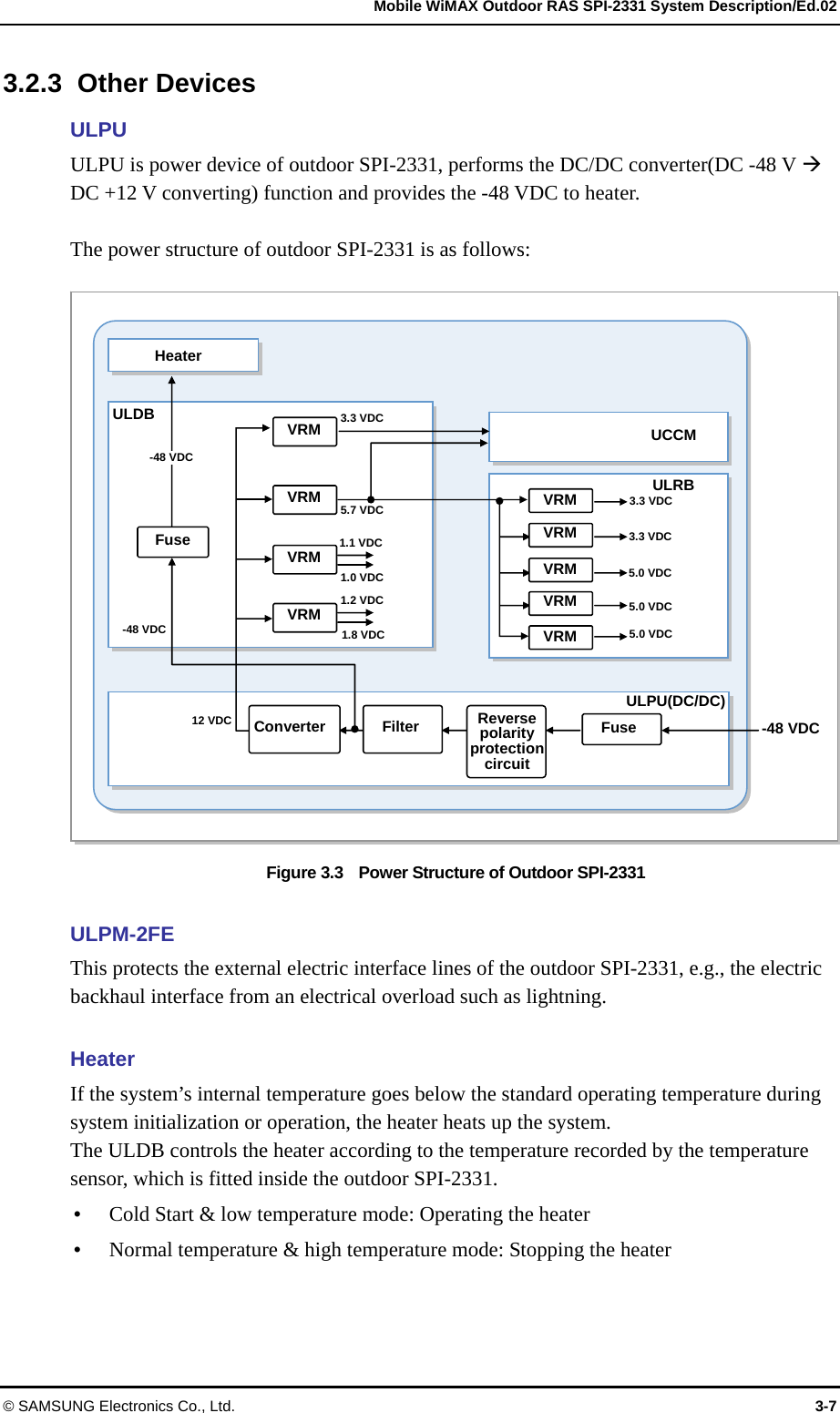
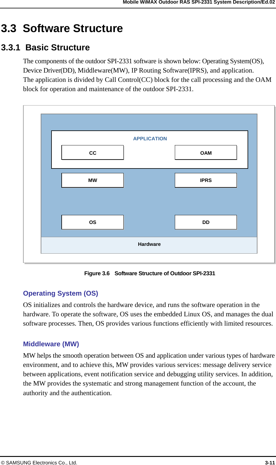
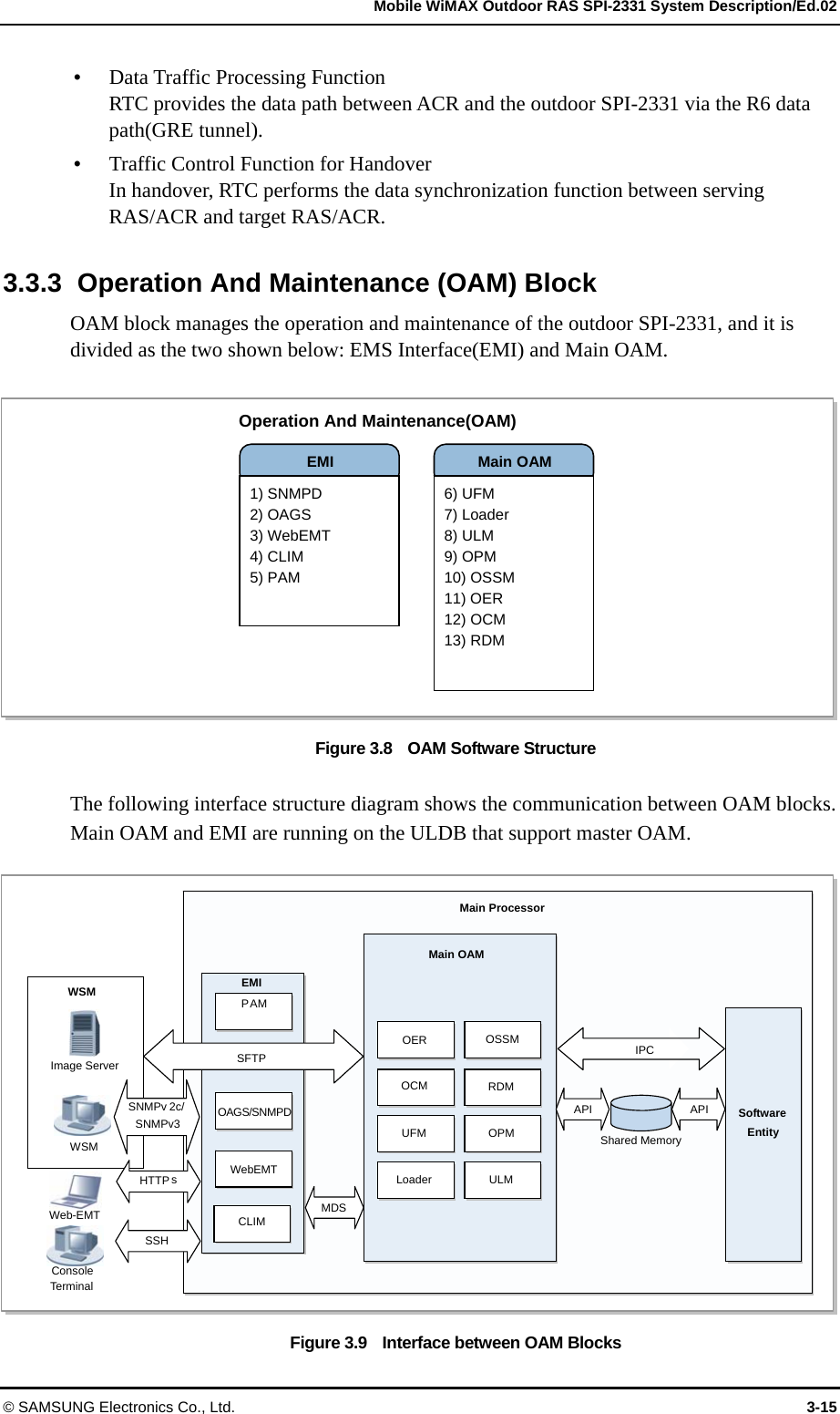
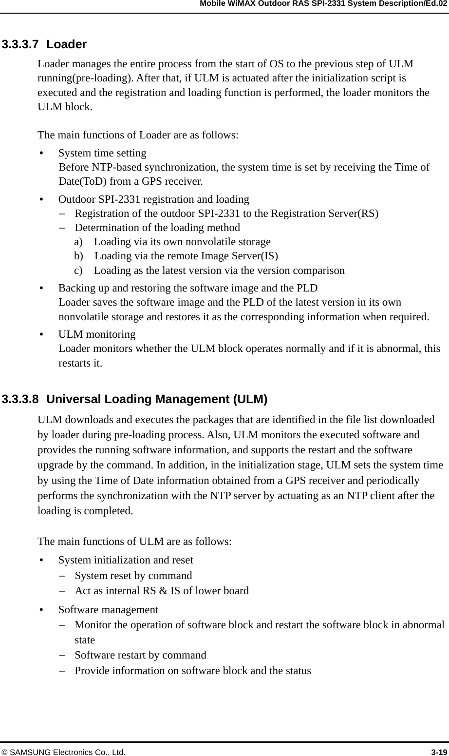
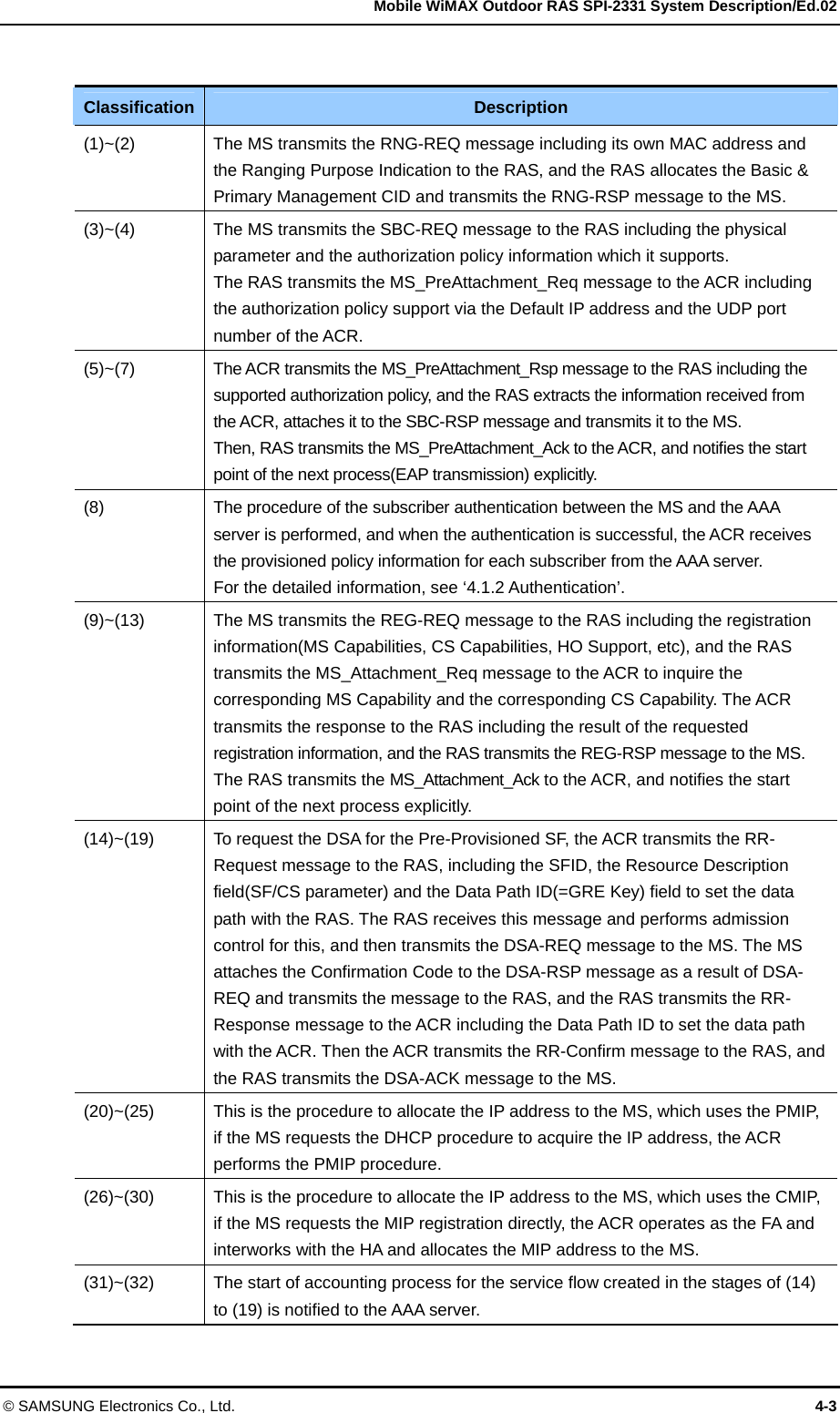
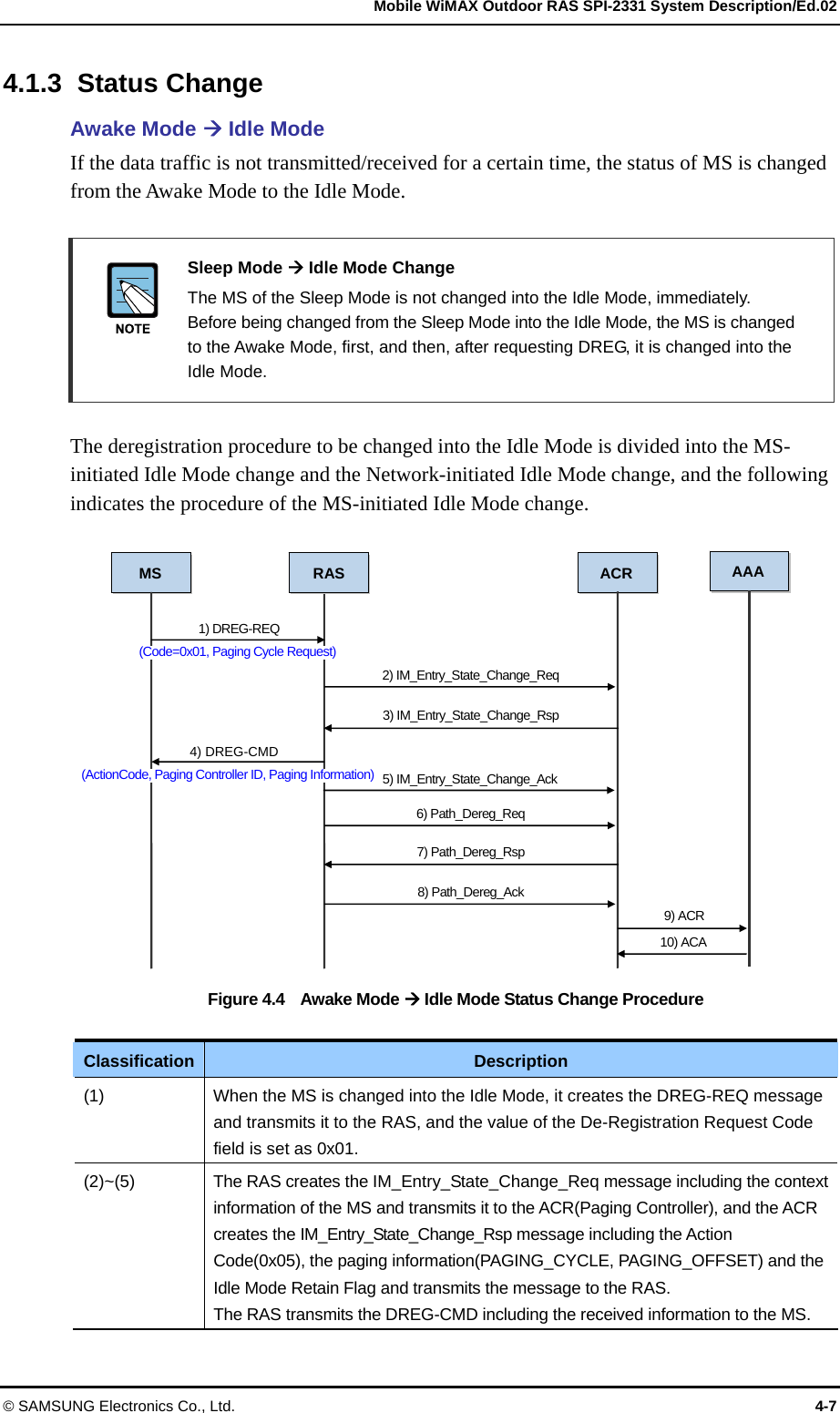
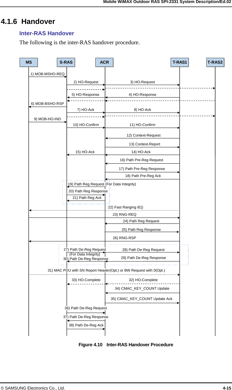
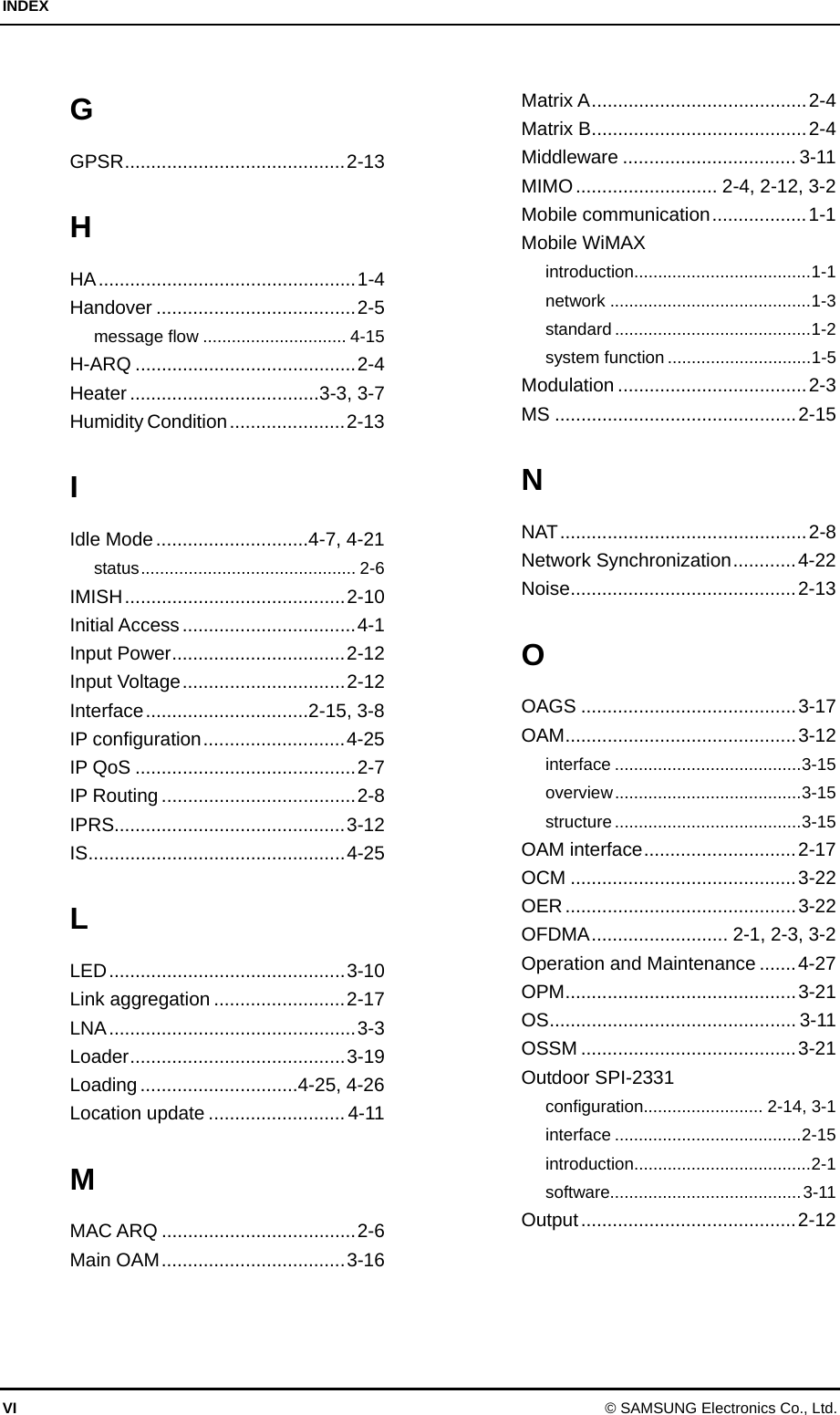
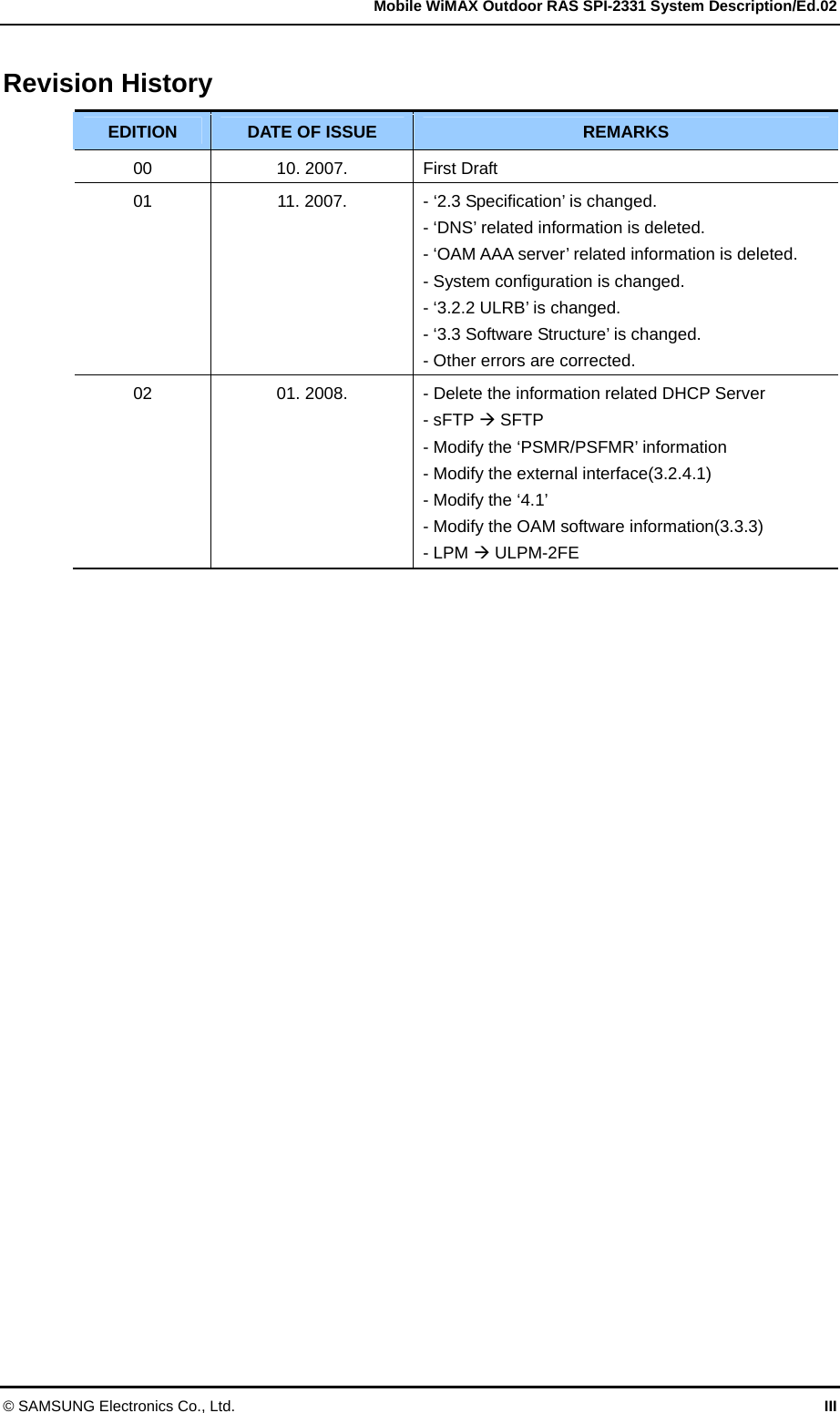
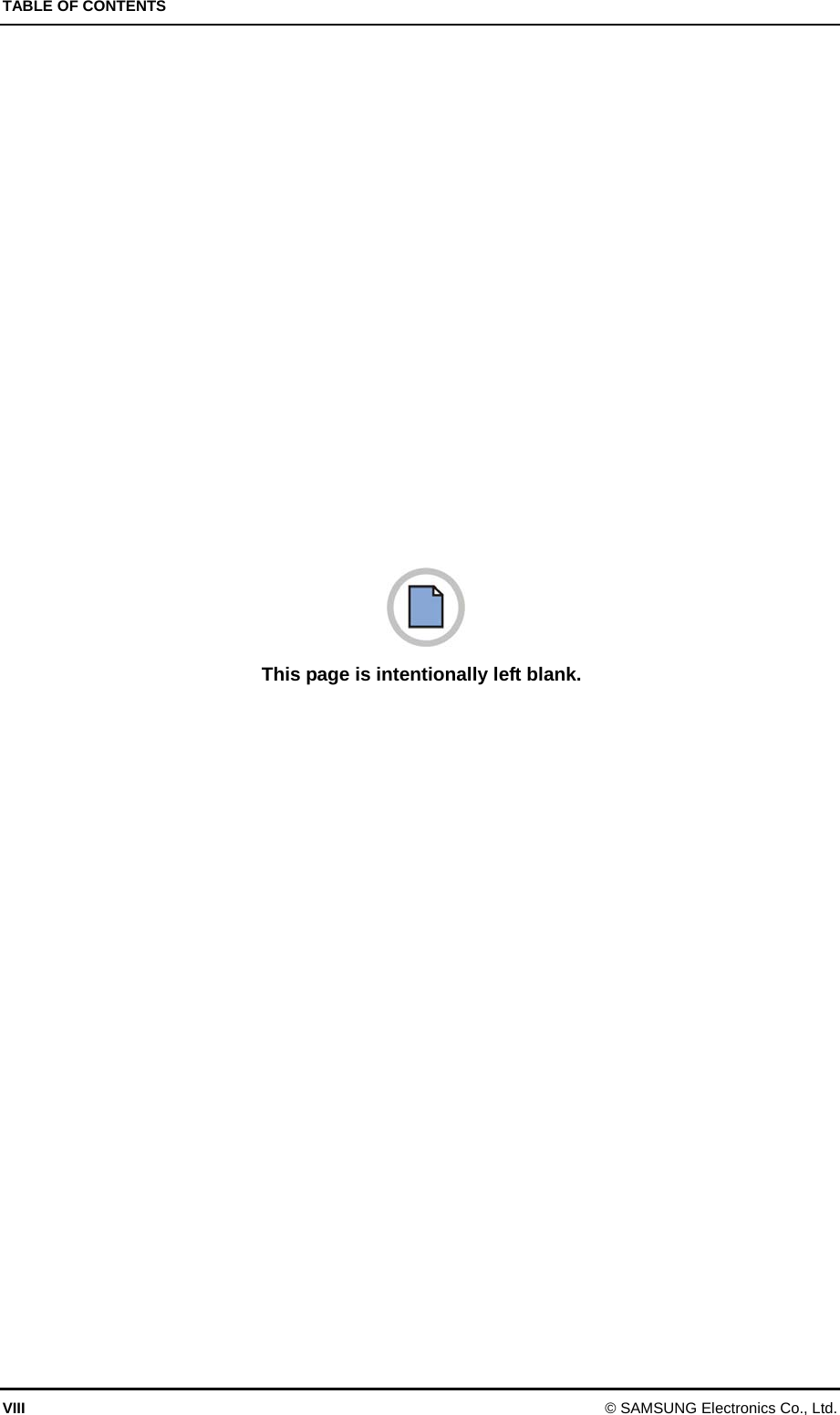
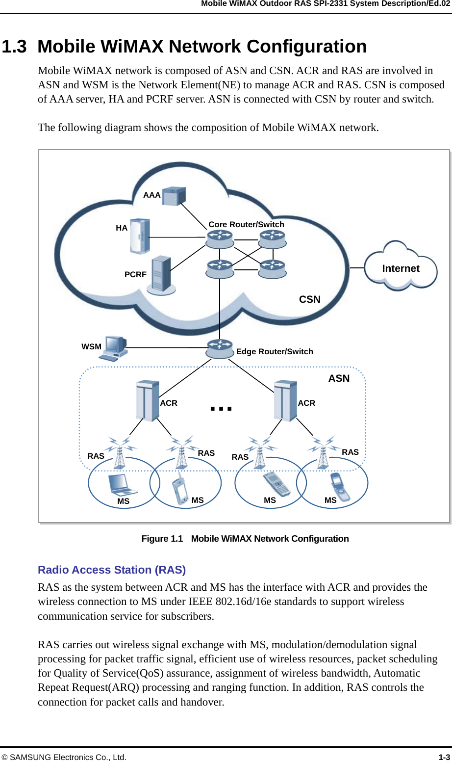
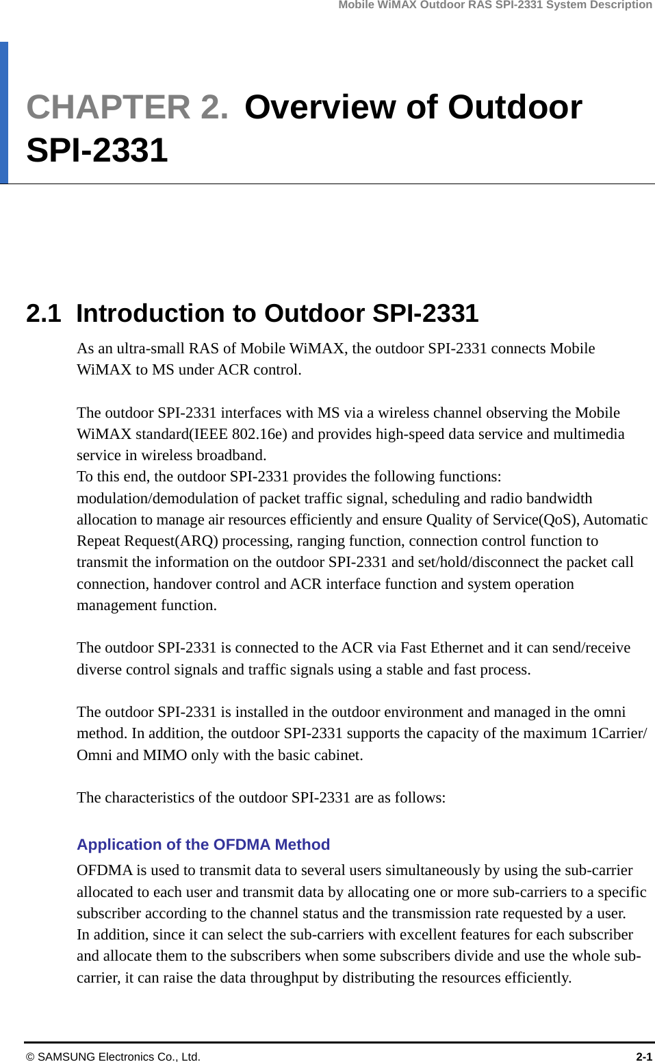
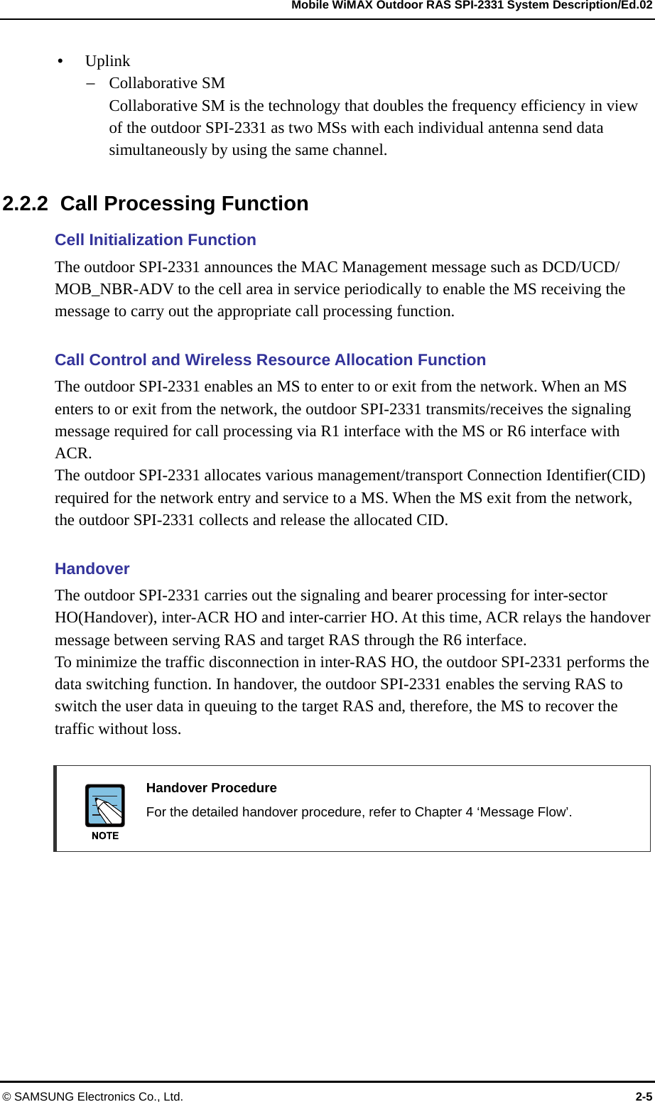
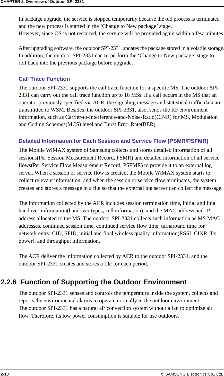
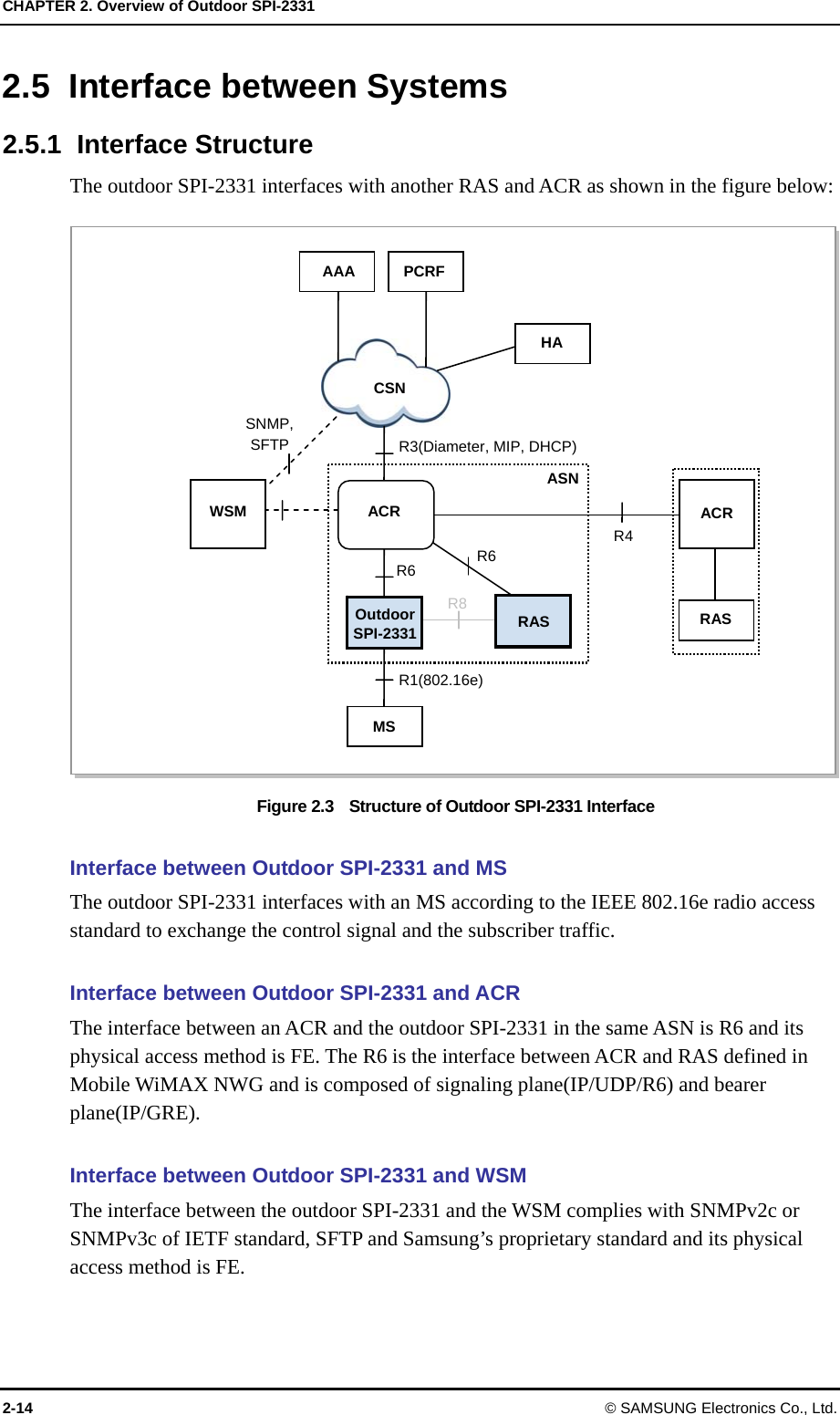
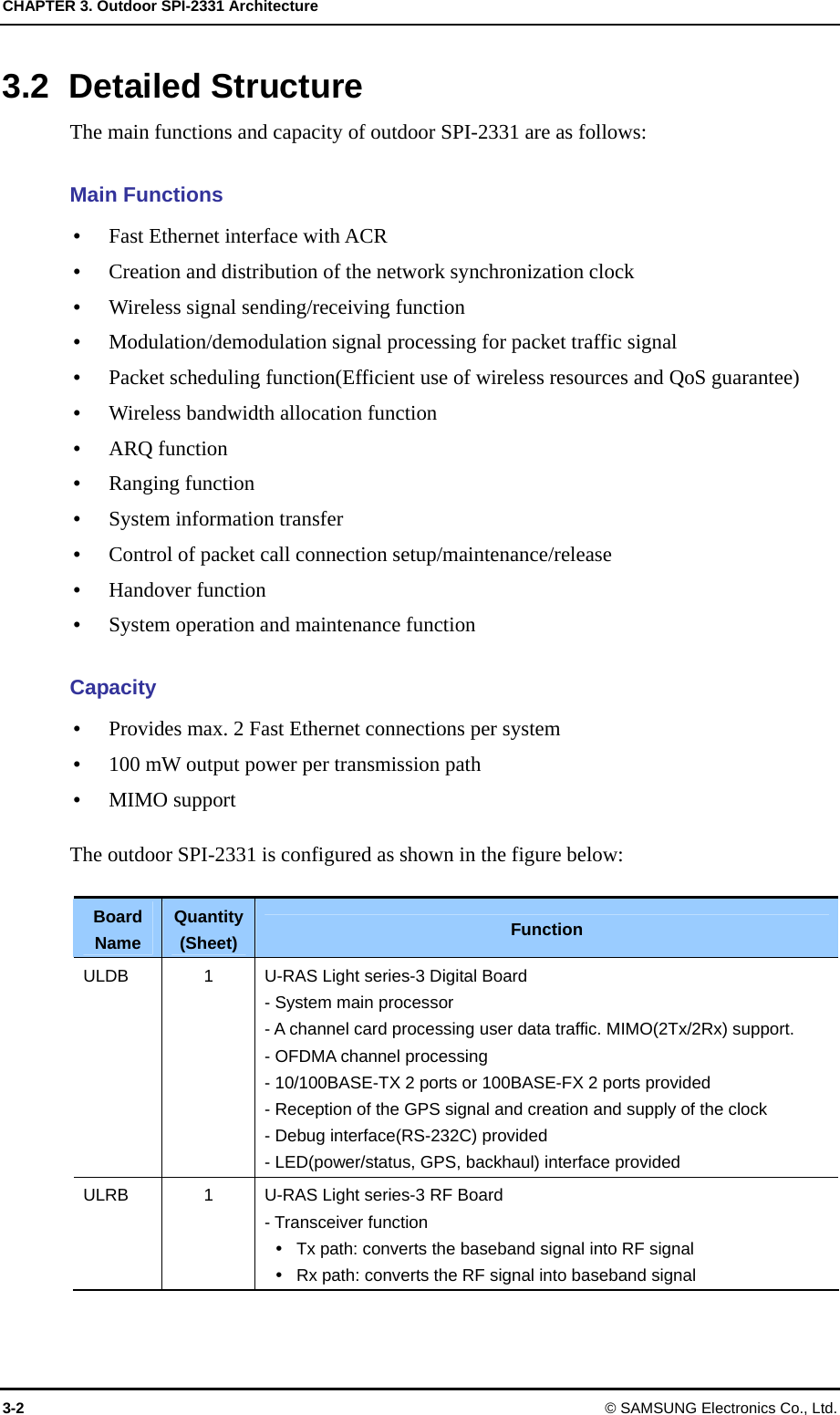
![CHAPTER 3. Outdoor SPI-2331 Architecture 3-8 © SAMSUNG Electronics Co., Ltd. 3.2.4 I/O Connector and LED The I/O connectors and LEDs at the top and bottom of the outdoor SPI-2331 cabinet are described below. Figure 3.4 I/O Connector and LED of Outdoor SPI-2331 3.2.4.1 I/O Connector Information I/O connector(external interface) structure of the outdoor SPI-2331 is as follows: Figure 3.5 External Interface of Outdoor SPI-2331 RF ProcessingControlBasebandProcessingNetworkInterfaceULDB ULRB GPSRBACKHAUL 0 CRAFT ANT A ANT B ULPU FilterTx power monitoring GPS 11.2M TDD UDE UDA(2Tx/6Rx) PWR ALM Power ConversionPWR BACKHAUL 1 GPS ANT ANT B ANT A PWR PWR ALM UDA CRAFT UDE BACKHAUL 1 Ground 11.2M TDD SYS/LINK GPS RF BACKHAUL 0 [Top of the Cainet] [Bottom of the Cainet]](https://usermanual.wiki/Samsung-Electronics-Co/SPI-2331022500/User-Guide-910633-Page-41.png)