Samsung Electronics Co SRC-BAMVC2 S-DAQ (WLAN) User Manual
Samsung Electronics Co Ltd S-DAQ (WLAN) Users Manual
UserManual.wiki
>
Samsung Electronics Co
>
SRC BAMVC2 User Manual
Users Manual-SRC-BAMVC2
Navigation menu
Upload a User Manual
Namespaces
Wiki Guide
HTML
PDF
Info
Views
User Manual
Discussion / Help
Navigation
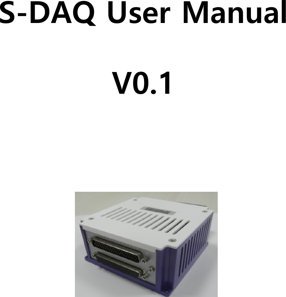
![S-DAQ User Manual 1 [ Revision History ] Version Date Change History Author Confirmed by V0.1 2015.09.06 SangHo Lee SangHo Lee](https://usermanual.wiki/Samsung-Electronics-Co/SRC-BAMVC2/User-Guide-2820589-Page-2.png)