Samsung Electronics Co SSAR1001 RFID Reader User Manual SSA R1001 ENG 1007 indd
Samsung Electronics Co Ltd RFID Reader SSA R1001 ENG 1007 indd
UserManual.wiki
>
Samsung Electronics Co
>
SSAR1001 User Manual
User manual
Navigation menu
Upload a User Manual
Namespaces
Wiki Guide
HTML
PDF
Info
Views
User Manual
Discussion / Help
Navigation


![English5PRODUCT INTRODUCTIONFEATURESThis product is an elegant-looking proximity reader which has the maximum read range of 10cm (4”), can be easily installed on a metal doorframe or the wall. Basically, both SSA-R1001 and SSA-R1101 use the same module with epoxy molding, which guarantees operation in any weather and environment condition. The two different bezels of two models are compatible with each other, meaning one can be replaced with the other according to the wall condition or the applicable situation. With its 3 two-color LED indicators as well as the built-in buzzer, this product is guaranteed to operate stably and correctly.13.56 MHz [MIFARE] Contactless Smart Card ReaderCompatible with ISO14443 Type A 3 Array LED Indicators (red and green) and Built-in Buzzer34 bit Wiegand Control of External LED IndicatorsControl of External BuzzerEpoxy MoldingReverse Polarity ProtectionWeatherproofWHAT’S INCLUDEDCheck if the following items are included in the product package.What’s included in SSA-R1001xGnSSA-R1001Bezel READER Module3.5x40mm screws (x2)3.5x25mm screws (x2)6x30mm Plastic Anchor (x2)Quick Guide CD ManualWhat’s included in SSA-R1101xGnSSA-R1101Bezel READER Module3.5x40mm screws (x2)3.5x25mm screws (x2)6x30mm Plastic Anchor (x2)Quick Guide CD Manual◆◆◆◆◆◆◆◆◆product introduction](https://usermanual.wiki/Samsung-Electronics-Co/SSAR1001/User-Guide-1186440-Page-5.png)
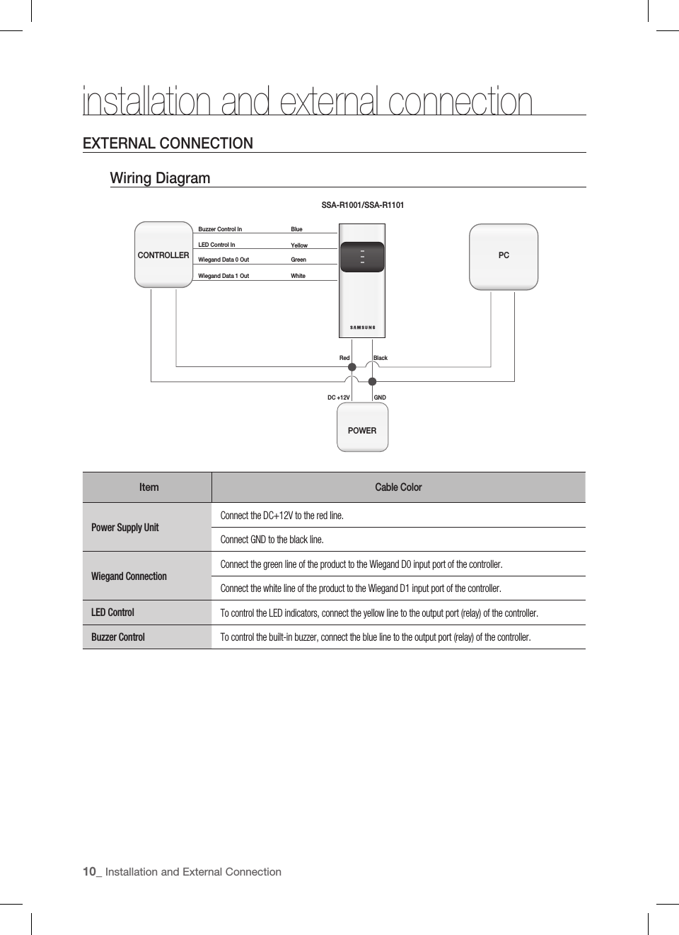
![English11INITIALIZATIONinitializationBASIC OPERATIONSInitial State (when the power is supplied)When you apply power to the reader, it will sound a beep before entering Standby with the red indicator turn on .Using the cardPresent the card to the reader until you hear a beep and the red indicator turns green.When the reader has transferred the data to the controller, it returns to Standby with the red indicator turned on and waits for reading the next card.LED ControlYou can control the LED indicator of the device at your preference.Connect the LED control input line (yellow) to the NO port of the controller relay output, and GND to the COM port.Set the I/O of the controller so that you can change the color of the LED indicators. While the LED control is working, the green indicator stays solid.This function not only enables you to change the color representing Standby from red to green, but it can be also applied to make various modifi cations according to the different I/O settings of the controller.For more information about the I/O settings of the controller, refer to the user manual of the controller.Buzzer ControlYou can control the buzzer of the device at your preference.You can confi gure the I/O settings of the controller so that it sounds a beep. While the buzzer control is working, the product keeps sounding the beep.The controller can use the I/O settings to set the buzzer control so that it sounds an additional beep for authorized or unauthorized access upon user authentication.Furthermore, you can make various modifi cations according to the different I/O settings of the controller.For more information about the I/O settings of the controller, refer to the user manual of the controller.Card reading is not available while the buzzer control is sounding the buzzer.MCardXYZ[\]^_`lzj lzjWizzhTzYWWW](https://usermanual.wiki/Samsung-Electronics-Co/SSAR1001/User-Guide-1186440-Page-11.png)