Samsung Electronics Co SSAS2000 RFID Reader User Manual
Samsung Electronics Co Ltd RFID Reader Users Manual
UserManual.wiki
>
Samsung Electronics Co
>
SSAS2000 User Manual
User manual
Navigation menu
Upload a User Manual
Namespaces
Wiki Guide
HTML
PDF
Info
Views
User Manual
Discussion / Help
Navigation
![English _ 7PRODUCT INTRODUCTIONWHAT’S INCLUDEDCheck if the following items are included in the product package.X Y Z[ \ ]^ _ `lzj lu{WizzhTzYWWWMain Unit Template O-rings (x5)xGn3.5 x 40mm Screws (x4)3.5 x 12mm Screws (x4)6 x 30mm Plastic Anchors (x4)Quick Guide Diodes (x2)(UF4004, 1N4001~4007)tGjMaster Card (x1) Cables (x4) CD Manual](https://usermanual.wiki/Samsung-Electronics-Co/SSAS2000/User-Guide-1186427-Page-7.png)
![8_ Product Introductionproduct introductionAT A GLANCEFront View System Status LEDIndicates the operation status of the system.KeypadUse this to confi gure or release settings as appropriate, or enter a card number.X Y Z[ \ ]^ _ `lzj lu{WizzhTzYWWW](https://usermanual.wiki/Samsung-Electronics-Co/SSAS2000/User-Guide-1186427-Page-8.png)
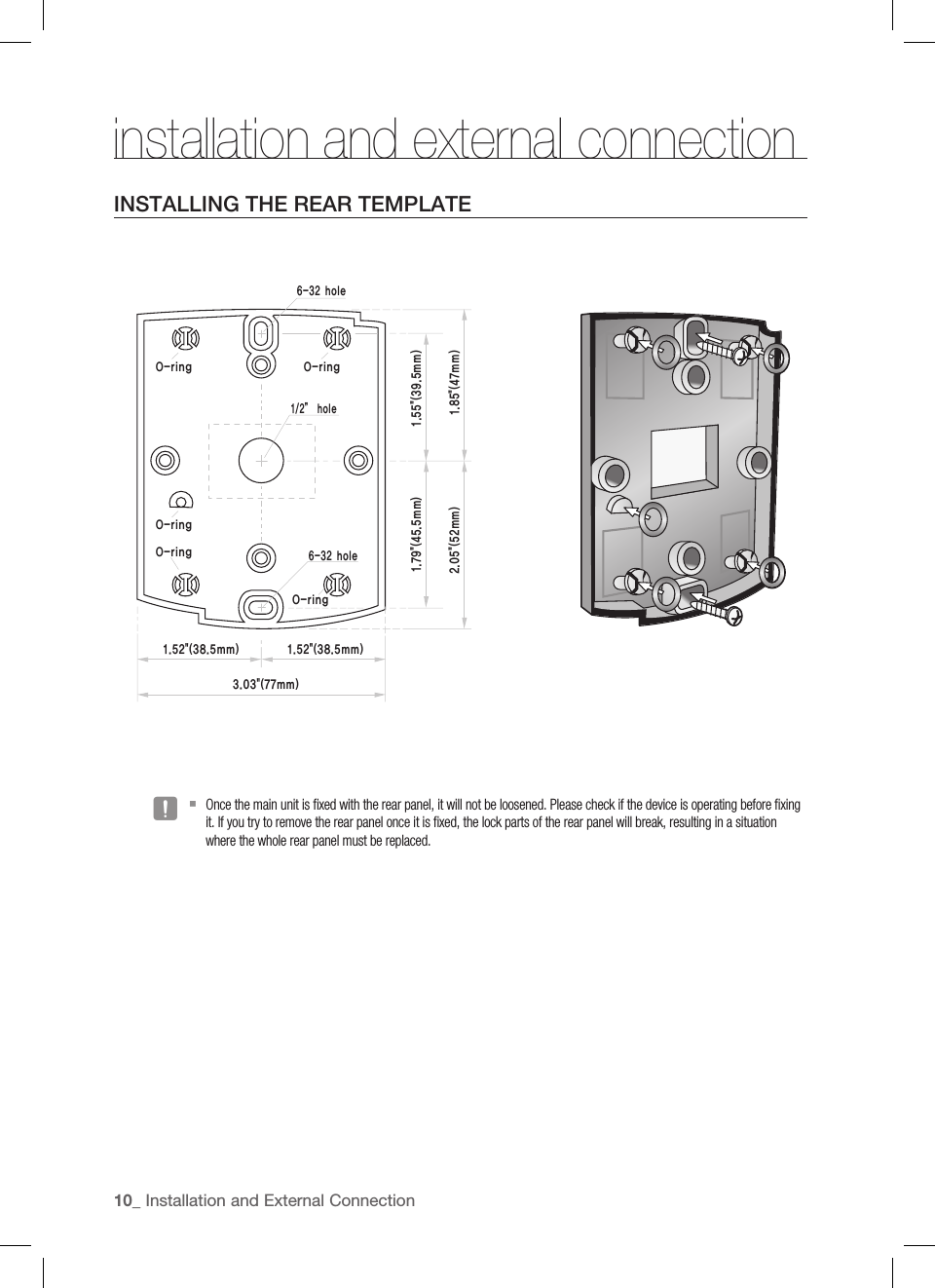
![English _ 11INSTALLATION AND EXTERNAL CONNECTIONCABLE SELECTIONItemCable TypeCable Type1Power (DC12V)DC Power This ProductBelden #9409, 18 AWG 2 Conductor, Unshielded (Maximum Allowable Distance : Within 3m)Belden #9409, 18 AWG 2 Conductor, Unshielded (Maximum Allowable Distance : Within 3m)2Reader (power and data)External Reader This ProductBelden #9512, 22 AWG 4 Conductor, Shielded Belden #9514, 22 AWG 8 Conductor, Shielded 3Door Contact Sensor Exit Button Sensor Input Input This ProductBelden #9512, 22 AWG 4 Conductor, Shielded Belden #9514, 22 AWG 8 Conductor, Shielded 4Door Lock,Alarm DeviceLock (Alarm) This ProductBelden #9409, 18 AWG 2 Conductor, Unshielded Belden #9409, 18 AWG 2 Conductor, Unshielded The cables should be thick enough to allow the maximum current consumed by the reader.J X Y Z[ \ ]^ _ `lzj lu{WizzhTzYWWWDC12VPower SupplyRF Reader Lock/AlarmSensor Input](https://usermanual.wiki/Samsung-Electronics-Co/SSAS2000/User-Guide-1186427-Page-11.png)
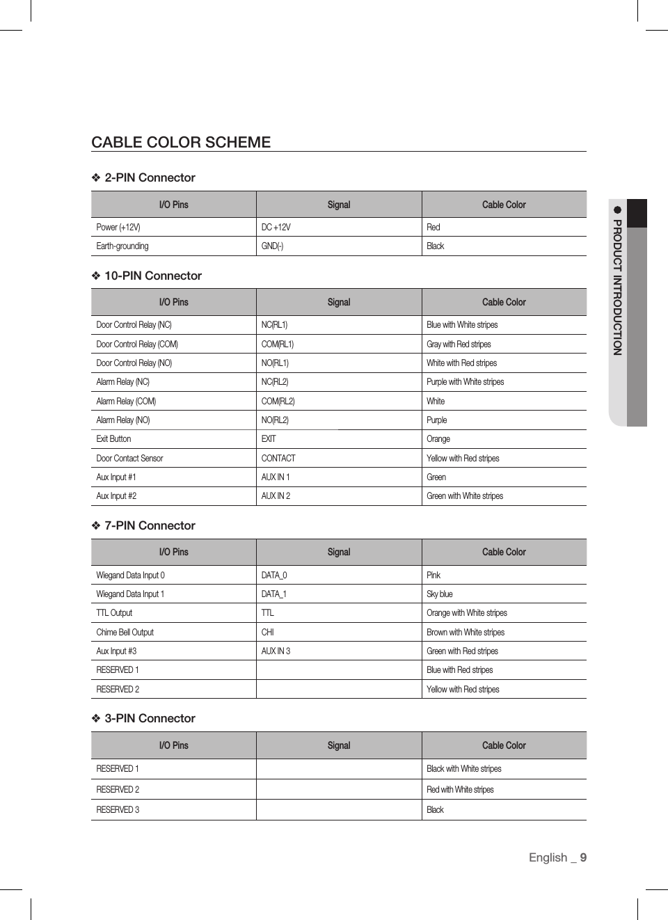
![12_ Installation and External Connectioninstallation and external connectionBYPASS DIODE CONNECTIONIf you connected an inductor (door locks or alarm device) to the output relay, there should occur a voltage surge while the inductor is turning on and off. If you do not connect a reverse diode to the relay, the surge voltage will cause damage to the electric circuit of the controller. To reduce this surge, it is recommended to connect a reverse diode between the devices.I/O CONNECTIONInput ConnectionConnect the DC 12V(+) of the power supply unit to the red line.Connect the GND(-) of the power supply unit to the black line.- Exit Button Connection Connect one line of the Exit button to the orange line.Connect the other line of the Exit button to GND.- Door Contact Sensor ConnectionConnect one line of the door contact sensor to the yellow with red stripes.Connect the other line of the door contact sensor to GND.- Auxiliary Input Device Connection (AUX 1 (green), AUX 2 (green with white stripes), AUX 3 (green with red stripes)Connect one line of the external input device to AUX 1, AUX 2, or AUX 3.Connect the other line of the external input device to GND(-).1.2.1.2.1.2.1.2.DC+DC-XYZ[\]^_`lzj lu{WizzhTzYWWWPUSHX Y Z[ \ ]^ _ `lzj lu{WizzhTzYWWWDoor Contact Sensor: Green with red stripes, GNDExit Button: Orange line, GNDLock/AlarmCathode Anode1N4004 ~ 1N4007 or equiv.DC + 12VPower SupplyBlack-Red+Door Contact SensorExit Button](https://usermanual.wiki/Samsung-Electronics-Co/SSAS2000/User-Guide-1186427-Page-12.png)
![English _ 13INSTALLATION AND EXTERNAL CONNECTIONOutput ConnectionConnect the 10-pin and 7-pin connectors of the controller as follows:- Door open (POWER FAIL SAFE) when the power is disconnected from the door lock (Door Relay)Connect the relay COM line (gray with red stripes for locking the door) to DC +12V.Connect the relay NC line (blue with white stripes for locking the door) to the plus(+) line of the door lock.Connect the minus (-) line of the door lock to GND (-).- Door close (POWER FAIL SECURE) when the power is disconnected from the door lock (Door Relay)Connect the relay COM line (gray with red stripes for locking the door) to DC +12V.Connect the relay NO line (white with red stripes for locking the door) to the plus (+) line of the door lock.Connect the minus (-) line of the door lock to GND (-).- Alarm Connection (Alarm Relay)Connect the relay COM (white for the alarm device) to DC +12V.Connect the relay NO line (purple for the alarm device) to the plus (+) line of the alarm device.Connect the minus (-) line of the alarm device to GND (-).- Chime Bell Connection (the chime bell operated by TTL-level signal must be installed in advance.)Connect the chime bell line (brown with white stripes) of the controller to DC +5V.Connect the GND line of the power supply unit to GND (-) of the chime bell.Press ESCto a0ctivate EthNeT chime bell.1.2.3.1.2.3.1.2.3.1.2.3.XYZ[\]^_`lzj lu{WizzhTzYWWWEXITDOORLOCKEXITCONTACTAUX IN#1CHIME+12VGNDGNDALARMRELAYCOMDOORRELAYCOMDOORRELAYNOALARMRELAYNOSIRENGND+12VDC 12VPOWERSUPPLYPIR SENSORCHIME BELLEXITBUTTONDOORCONTACTCathode Anode1N4004~1N4007 or equiv.](https://usermanual.wiki/Samsung-Electronics-Co/SSAS2000/User-Guide-1186427-Page-13.png)
![14_ Installation and External Connectioninstallation and external connectionEXTERNAL READER CONNECTION- Proximity Reader ConnectionConnect the DC 12V(+) of the power supply unit to the plus (+) line of the reader.Connect the GND(-) line of the power supply unit to the minus (-) line of the reader.Connect the Wiegand data input line 0 of the proximity reader to the purple line.Connect the Wiegand data input line 1 of the proximity reader to the sky blue line.For a list of compliant readers (external readers), see the followings:- Standard 26bit Wiegand format proximity reader1.2.3.4.•(+)(-)X Y Z[ \ ]^ _ `lzj lu{WizzhTzYWWWWiegand DATA0(Pink)Wiegand DATA0(Sky blue)검은색-빨간색+GNDDC+12V](https://usermanual.wiki/Samsung-Electronics-Co/SSAS2000/User-Guide-1186427-Page-14.png)
![English _ 15INITIALIZATIONinitializationBASIC OPERATIONSInitial StatusWhile the product is working normally, the orange LED indicator blinks every one second.Predefi ned Operation for a Registered CardWhen reading a registered card, it opens the door with the melody.Exit Button OperationIf you press the Exit button, the door will be opened.Predefi ned Operation for an Unregistered CardWhen reading an unregistered card, it produces an alarm with the melody for two seconds. You can specify the use of the alarm and change the operation time.Secure Mode OperationThe person who exits the last can set the secure mode using the keypad.Set Secure mode: Press the 9button twice and press ENT.Release secure mode: Present and authenticate a registered card or the Master Card to the reader. You can use the keypad to specify the delayed start time for the Secure mode. (Refer to the delayed start time in Secure mode on page 28.)For effective security purposes, you can set to activate the sensors (via auxiliary input ports) only in Secure mode.Duress AlarmIf you are forced to open the door under a robber’s control, enter the Duress password and press ENTwith the number of your registered card (or PIN). (See page 24.)How to use the chime bellWhen you have connected and set the chime bell, press ESC to ring the chime bell. (See page 34.)MEXITX Y Z[ \ ]^ _ `lzj lu{WizzhTzYWWWtGj](https://usermanual.wiki/Samsung-Electronics-Co/SSAS2000/User-Guide-1186427-Page-15.png)
![16_ InitializationinitializationWIEGAND OUTPUT SETUPYou can transfer data of the card read by SSA-S2000 in the 26-bit Wiegand output format.Enabling this function will disable the TTL output and the chime bell sound.To enable the 26-bit Wiegand output, you must manipulate the switch panel (SW1 and SW2) on the rear of the product.See the table below to make adjustment as needed.Output FormatSW1 #1 SW1 #2 SW2 #1 SW2 #2Orange line with white stripes Brown line with white stripesON OFF ON OFF TTL Output Chime Bell OutputOFF ON OFF ON Wiegand Data0 Wiegand Data1In the 26-bit Wiegand output mode, you can not initialize the product by short-circuiting cables.INITIALIZATIONIf you have the Master Card registered, you can use it to initialize the device.Present the Master Card to the device.Press the 9button twice and press ENT.The system will restore the factory default settings with all LED indicators blinking.Initializing the system will lose all data.If the product works abnormally, use initialization to restore the default settings. 1.2.❖J1.2.3.MX Y Z[ \ ]^ _ `lzj lu{WizzhTzYWWWtGjX Y Z[ \ ]^ _ `lzj lu{WizzhTzYWWW](https://usermanual.wiki/Samsung-Electronics-Co/SSAS2000/User-Guide-1186427-Page-16.png)
![English _ 17INITIALIZATIONFORCED INITIALIZATION WITH EXTERNAL LINETurn off the product, shortcircuit between the green line and the orange line with white stripes, and turn it back on.When the initialization is completed, 3 LED indicators are blinking with a beep.Restore the connection of the two lines back to their original state.HARDWARE FORCIBLE INITIALIZATIONThis is to initialize the product forcibly by disassembling it.Use this method only if you have lost the Master Card or the password, or if the forcible initialization with the external line failed.Turn off the product and detach it from the installation site, then loosen the screw (x4) on each corner to disassemble it as shown.Apply power to the product and short-circuit the jumper for one second as shown.When the initialization is completed, 3 LED indicators are blinking.Turn off the product and restore it to the original installation state.1.2.3.1.2.3.4.X Y Z[ \ ]^ _ `lzj lu{WizzhTzYWWW12VGNDGreenOrange with white stripes Connect (Short-circuit)Connect (Short-circuit)](https://usermanual.wiki/Samsung-Electronics-Co/SSAS2000/User-Guide-1186427-Page-17.png)
![18_ Reader Mode Setup- You can specify the operation mode for the device.- Once a mode is specifi ed, it will not switch until you perform the initialization.- You must keep the Master Card in safe for later use as it is required for your change to the device settings.- If progression is halted for more than one minute during any of the following processes, the operation mode of the reader will return to the previous state.READER MODE SETUP (RF ONLY)No Master Card or Master PIN is ever registered.If you remember the Master Card or the Master PIN was registered, initialize the product and try again.When you turn on the product, all of the 3 LED indicators will fl ash with a beep.No flashing of the 3 indicators denotes that the reader mode is already specified.Press Button 0and Button1 in sequence and press ENT.When the mode is specified, only the green LED indicator flashes.Present a card that you want to register as the Master Card to the device. When the Master Card is registered, only the red LED indicator flashes.Present cards to register with the device one after another, and the device will register them with a beep. If you don’t want to register the cards right now, simply jump to Step 5 above without through Step 4 above.Present the registered Master Card to the product once again.The device enters Standby mode with only the orange LED indicator flashing.1.•2.3.4.5.6.reader mode setupX Y Z[ \ ]^ _ `lzj lu{WizzhTzYWWWX Y Z[ \ ]^ _ `lzj lu{WizzhTzYWWWÎÎÎtGjX Y Z[ \ ]^ _ `lzj lu{WizzhTzYWWWtGjX Y Z[ \ ]^ _ `lzj lu{WizzhTzYWWWX Y Z[ \ ]^ _ `lzj lu{WizzhTzYWWW](https://usermanual.wiki/Samsung-Electronics-Co/SSAS2000/User-Guide-1186427-Page-18.png)
![English _ 19READER MODE SETUPREADER MODE SETUP (RF + P/W) No Master Card or Master PIN is ever registered.If you remember the Master Card or the Master PIN was registered, initialize the product and try again.When you turn on the product, all of the 3 LED indicators will fl ash with a beep.No flashing of the 3 indicators denotes that the reader mode is already specified.Press Button 0 and Button 2in sequence and press ENT.Present a card that you want to register as the Master Card to the device. When the Master Card is registered, only the red LED indicator flashes.Present a card to the device, enter the 4-6 digit password and press ENT. If you don’t want to register the cards right now, simply jump to Step 5 above without through Step 4 above.Present the registered Master Card to the product once again.The device enters Standby mode with only the orange LED indicator flashing.READER MODE SETUP (PIN ONLY)No Master Card or Master PIN is ever registered.If you remember the Master Card or the Master PIN was registered, initialize the product and try again.When you turn on the product, all of the 3 LED indicators will fl ash with a beep.No flashing of the 3 indicators denotes that the reader mode is already specified.Press Button 0 and Button 3 in sequence and press ENT.When the mode is specified, only the green LED indicator flashes.Enter the 4-6 digit Master PIN number and press ENT.When the Master PIN is registered, only the red LED indicator flashes.Enter a PIN number to register (4-6 digits) and pressRepeat the step above if you want to register PIN numbers with the device in sequence.If you don’t want to register the PIN number right now, simply jump to Step 5 above without through Step 4 above.Enter the 4-6 digit Master PIN number again and press ENT.The device enters Standby mode with only the orange LED indicator flashing.1.•2.3.4.5.6.1.•2.3.4.5.6.X Y Z[ \ ]^ _ `lzj lu{WizzhTzYWWWX Y Z[ \ ]^ _ `lzj lu{WizzhTzYWWWX Y Z[ \ ]^ _ `lzj lu{WizzhTzYWWWX Y Z[ \ ]^ _ `lzj lu{WizzhTzYWWWX Y Z[ \ ]^ _ `lzj lu{WizzhTzYWWWÎÎX Y Z[ \ ]^ _ `lzj lu{WizzhTzYWWWÎtGjtGj](https://usermanual.wiki/Samsung-Electronics-Co/SSAS2000/User-Guide-1186427-Page-19.png)
![20_ Reader Mode Setupreader mode setupREADER MODE SETUP (RF/PIN COMBINATION MODE)No Master Card or Master PIN is ever registered.If you remember the Master Card or the Master PIN was registered, initialize the product and try again.When you turn on the product, all of the 3 LED indicators will fl ash with a beep.No flashing of the 3 indicators denotes that the reader mode is already specified.Press Button 0 and Button 5 in sequence and press ENT.Present a card that you want to register as the Master Card to the device. When the Master Card is registered, only the red LED indicator flashes.Present cards or PIN numbers (4-6 digits) to register with the device one after another, and the device will register them with a beep. If you don’t want to register the cards right now, simply jump to Step 5 above without through Step 4 above.Present the registered Master Card to the product once again.The device enters Standby mode with only the orange LED indicator flashing.ENABLING KEYPAD INPUT FOR THE CARD NUMBEREnsure that you must have registered the Master Card.Present the Master Card to the device. Press Button 7 and Button 3in sequence and press ENT.Repeat Step 1 above to release the specified mode, press Button 7 and Button 4 in sequence, and press ENT.You can set the device to allow you to control the door by entering the 8 digit card number using the keypad.The default is “Keypad Input Disabled”.1.•2.3.4.5.6.1.2.•MX Y Z[ \ ]^ _ `lzj lu{WizzhTzYWWWX Y Z[ \ ]^ _ `lzj lu{WizzhTzYWWWX Y Z[ \ ]^ _ `lzj lu{WizzhTzYWWWX Y Z[ \ ]^ _ `lzj lu{WizzhTzYWWWÎÎX Y Z[ \ ]^ _ `lzj lu{WizzhTzYWWWtGjtGjorX Y Z[ \ ]^ _ `lzj lu{WizzhTzYWWWtGjX Y Z[ \ ]^ _ `lzj lu{WizzhTzYWWW](https://usermanual.wiki/Samsung-Electronics-Co/SSAS2000/User-Guide-1186427-Page-20.png)
![English _ 21USER MANAGEMENTuser managementTO REGISTER CARDS IN RF ONLY MODEEnsure that you must have registered the Master Card and the device is specifi ed in RF ONLY mode.Present the Master Card to the device. When the mode is specifi ed, only the green LED indicator fl ashes.Press Button 1 and Button 1 in sequence and press ENT.When the device enters Standby, only the red LED indicator flashes.Present a card to the device, it will be registered with a beep. Repeat this step if you want to register multiple cards.Present the Master card to the device again, and the device will switch to normal mode. If no input is made for 20 seconds, the device will switch to normal mode.REGISTERING CARDS IN A COMBINATION OF RF AND P/W MODESEnsure that you must have registered the Master Card and the device is specifi ed in RF + P/W mode.Present the Master Card to the device. When the mode is specifi ed, only the green LED indicator fl ashes.Press Button 1 and Button 2 in sequence and press ENT.When the device enters Standby, only the red LED indicator flashes.Present a card to the device, enter the 4-6 digit password and press ENT. Repeat this step if you want to register multiple cards.Present the Master card to the device again, and the device will switch to normal mode. If no input is made for 20 seconds, the device will switch to normal mode.1.2.3.4.1.2.3.4.X Y Z[ \ ]^ _ `lzj lu{WizzhTzYWWWX Y Z[ \ ]^ _ `lzj lu{WizzhTzYWWWÎÎX Y Z[ \ ]^ _ `lzj lu{WizzhTzYWWWÎX Y Z[ \ ]^ _ `lzj lu{WizzhTzYWWWtGjX Y Z[ \ ]^ _ `lzj lu{WizzhTzYWWWtGjX Y Z[ \ ]^ _ `lzj lu{WizzhTzYWWWX Y Z[ \ ]^ _ `lzj lu{WizzhTzYWWWÎÎX Y Z[ \ ]^ _ `lzj lu{WizzhTzYWWWtGjX Y Z[ \ ]^ _ `lzj lu{WizzhTzYWWWtGj](https://usermanual.wiki/Samsung-Electronics-Co/SSAS2000/User-Guide-1186427-Page-21.png)
![22_ User Managementuser managementTO REGISTER CARDS IN PIN MODEEnsure that you must have registered the Master Card and the device is specifi ed in PIN mode.Enter the Master PIN number and press ENT.When the mode is specifi ed, only the green LED indicator fl ashes.Press Button 1 and Button 3 in sequence and press ENT.When the mode is specifi ed, only the green LED indicator fl ashes.If you enter a user number (4-6 digits) to register and press ENT, the PIN number will be registered with a beep. Repeat this step if you want to register multiple PIN numbers.Present the Master PIN number to the device again, and the device will switch to normal mode. If no input is made for 20 seconds, the device will switch to normal mode. REGISTERING CARDS IN RF CARD / PIN COMBINATION MODEEnsure that you must have registered the Master Card and the device is specifi ed in RF Card / PIN combination mode.Present the Master Card to the device. When the mode is specifi ed, only the green LED indicator fl ashes.Press Button 1 and Button 5 in sequence and press ENT.When the device enters Standby, only the red LED indicator fl ashes.Present cards or PIN numbers (4-6 digits) to register with the device one after another, and the device will register them with a beep. Repeat this step if you want to register multiple cards or PIN numbers.Present the Master PIN number to the device again, and the device will switch to normal mode. If no input is made for 20 seconds, the device will switch to normal mode.The door may be accessed in two ways: using the card or the PIN number.1.2.3.4.1.2.3.4.MX Y Z[ \ ]^ _ `lzj lu{WizzhTzYWWWtGjX Y Z[ \ ]^ _ `lzj lu{WizzhTzYWWWX Y Z[ \ ]^ _ `lzj lu{WizzhTzYWWWÎX Y Z[ \ ]^ _ `lzj lu{WizzhTzYWWWÎX Y Z[ \ ]^ _ `lzj lu{WizzhTzYWWWtGjorX Y Z[ \ ]^ _ `lzj lu{WizzhTzYWWW<Master PIN>X Y Z[ \ ]^ _ `lzj lu{WizzhTzYWWWÎÎX Y Z[ \ ]^ _ `lzj lu{WizzhTzYWWWX Y Z[ \ ]^ _ `lzj lu{WizzhTzYWWW<Master PIN><User Number> <User Number>](https://usermanual.wiki/Samsung-Electronics-Co/SSAS2000/User-Guide-1186427-Page-22.png)
![English _ 23USER MANAGEMENTTO DELETE A REGISTERED CARD OR PIN NUMBEREnsure that you must have registered the Master Card or the Master PIN number and the device is specifi ed in a certain mode. This is applicable in all modes.Enter the Master Card or Master PIN. When the mode is specifi ed, only the green LED indicator fl ashes.Press Button 1 and Button 4 in sequence and press ENT.When the device enters Standby, only the red LED indicator fl ashes.Present a card or PIN number to delete.Repeat this step if you want to register multiple cards or PIN numbers.Present the Master card to the device again, and the device will switch to normal mode. If no input is made for 20 seconds, the device will switch to normal mode.1.2.3.4.X Y Z[ \ ]^ _ `lzj lu{WizzhTzYWWWtGjX Y Z[ \ ]^ _ `lzj lu{WizzhTzYWWWX Y Z[ \ ]^ _ `lzj lu{WizzhTzYWWWÎX Y Z[ \ ]^ _ `lzj lu{WizzhTzYWWWÎX Y Z[ \ ]^ _ `lzj lu{WizzhTzYWWWtGjor](https://usermanual.wiki/Samsung-Electronics-Co/SSAS2000/User-Guide-1186427-Page-23.png)
![24_ Basic Setupbasic setupDURESS ALARMIf you are forced to open the door under the control of a criminal such as a robber, enter the predefi ned password with the number of your registered card (or PIN), which outputs the emergency TTL signal.Present the Master Card to the device.Press Button 2and Button 9in sequence and press ENT.Enter the two-digit Duress code and press ENT.The default code is set to “00”. However, the number “77” can not be used because it is set for the Secure mode.TO SPECIFY THE RETRY COUNT FOR AN UNREGISTERED IDYou can specify the retry count for authentication with an unregistered card or PIN.If the retry count exceeds the set limit, the keypad input will be suspended for the next one minute. (You can specify the keypad input suspension time in “To specify the keypad input suspension time if the retry count with an unregistered ID exceeds the limit” on page 25.)Present the Master Card to the device.Press Button 8,2and Button ENTin sequence and press ENT.Enter the two-digit retry count and press ENT.You can specify a number from 00 to 99.The retry count for an unregistered ID is defaulted to “05”.1.2.3.•1.2.3.••X Y Z[ \ ]^ _ `lzj lu{WizzhTzYWWWtGjX Y Z[ \ ]^ _ `lzj lu{WizzhTzYWWWX Y Z[ \ ]^ _ `lzj lu{WizzhTzYWWWtGjX Y Z[ \ ]^ _ `lzj lu{WizzhTzYWWW](https://usermanual.wiki/Samsung-Electronics-Co/SSAS2000/User-Guide-1186427-Page-24.png)
![English _ 25BASIC SETUPX Y Z[ \ ]^ _ `lzj lu{WizzhTzYWWWtGjX Y Z[ \ ]^ _ `lzj lu{WizzhTzYWWWTO SPECIFY THE KEYPAD INPUT SUSPENSION TIME IF THE RETRY COUNT WITH AN UNREGISTERED ID EXCEEDS THE LIMITPresent the Master Card to the device.Press Button 6and Button 0in sequence and press ENT.Enter the two-digit keypad input suspension time (unit: minute) and press ENT. The default is set to “01”.You can specify a time from 01 to 99 minutes.You can specify the time of the keypad input suspension (followed by an alarm) if an unregistered user keeps trying to open the door for certain times (the code number is set to “82”.TO SPECIFY THE DELAYED START TIME IN SECURE MODEPresent the Master Card to the device.Press Button 8and Button 0in sequence and press ENT.Enter the two-digit delayed start time (unit: minute) and press ENT. The default is set to “00”.See the table below for your reference.Secure Mode When the last person set the Secure mode before exiting the offi ce, the external sensors will get activated since then.Delayed StartIf the external sensors get activated right after you set the Secure mode, your motion will be detected before you can get out of the secure area, which will trigger the alarm. Thus, it is recommended to set the Secure mode to get activated after a certain time.Enter the delayed start time by the minute; the sensor operation in Secure mode must have been specifi ed in advance. (Refer to “Alarm Operation Time for Auxiliary Input” on pages 31-32)1.2.3.•M1.2.3.•MX Y Z[ \ ]^ _ `lzj lu{WizzhTzYWWWtGjX Y Z[ \ ]^ _ `lzj lu{WizzhTzYWWW](https://usermanual.wiki/Samsung-Electronics-Co/SSAS2000/User-Guide-1186427-Page-25.png)
![26_ Basic Setupbasic setupTO SPECIFY THE OPERATION TIME OF THE DOOR CONTACT SENSORThe Door Contact sensor detects the opening of the door.If the door is forcibly opened by an unregistered user, the Door Contact Sensor will perform the predefi ned alarm operation after the set time. (For setting the alarm operation time, refer to the alarm output for an input error of the Door Contact Sensor on page 31.)Present the Master Card to the device.Press Button 8and Button 1in sequence and press ENT.Enter the two-digit operation time (unit: second) and press ENT.The default is set to “00” second, which means the Door Contact Sensor is disabled.You can specify from 01 to 99.TO SPECIFY THE LIMITED TIME FOR THE KEYPAD INPUTWhen it passes a certain time during your setting using the keypad , all your settings will be ignored and return to the initial state.Specify the delay time between the input of the last key and restoring the previous state.Present the Master Card to the device.Press Button 8and Button 3in sequence and press ENT.Enter the two-digit operation time (unit: second) and press ENT.The default is set to “20” second.You can specify from 10 to 99.1.2.3.••1.2.3.•X Y Z[ \ ]^ _ `lzj lu{WizzhTzYWWWtGjX Y Z[ \ ]^ _ `lzj lu{WizzhTzYWWWX Y Z[ \ ]^ _ `lzj lu{WizzhTzYWWWtGjX Y Z[ \ ]^ _ `lzj lu{WizzhTzYWWW](https://usermanual.wiki/Samsung-Electronics-Co/SSAS2000/User-Guide-1186427-Page-26.png)
![English _ 27BASIC SETUPTO SPECIFY THE ALARM OUTPUT PORT FOR THE DISMANTLED DEVICESpecify the alarm type for the dismantled device. The alarm rings from the dismantlement of the device to the authentication of the Master Card or a registered card.Present the Master Card to the device.Press Button 8and Button 4in sequence and press ENT.Provide the alarm output port and press ENT.The default is set to “02” (alarm).For the alarm output port settings, refer to the output port table on page 29.The alarm for the dismantled device occurs regardless of the operation mode of either Normal or Secure so you simply specify the operation port only. (To specify the operation port, refer to the operation port settings in the output port setting table on page 29.)TO OPEN OR CLOSE THE ENTRY DOORFollow the step below If you want to keep the door open regardless of the authentication process using the Master Card or PIN.Present the Master Card to the device.Press Button 4and Button 1in sequence and press ENT.To release opening the door, repeat Step 1 above, select the <42> buttons and press ENT.1.2.3.••1.2.•X Y Z[ \ ]^ _ `lzj lu{WizzhTzYWWWtGjX Y Z[ \ ]^ _ `lzj lu{WizzhTzYWWWX Y Z[ \ ]^ _ `lzj lu{WizzhTzYWWWtGjX Y Z[ \ ]^ _ `lzj lu{WizzhTzYWWW](https://usermanual.wiki/Samsung-Electronics-Co/SSAS2000/User-Guide-1186427-Page-27.png)
![28_ Basic Setupbasic setupTO SET OR RELEASE THE QUICK MODEThe QUICK mode is applicable to RF ONLY mode (01) and PIN ONLY mode (03) and RF/PIN combination mode (05), which enables you to open the door by simply pressing ENTwithout the need of the PIN number. (This is useful for the normal business hours when the door entries and exits occur frequently.)Present the Master Card to the device.Press Button 4and Button 3in sequence and press ENT.To release the QUICK mode, repeat Step 1 above, select the <4 4> buttons and press ENT.The default is set to “not used”.TO SET OR RELEASE THE TOGGLE MODE FOR THE DOOR RELAYIn the Toggle mode, the door opens if it is closed or vice versa by presenting a registered card or entering the PIN.Present the Master Card to the device.Press Button 4and Button 5in sequence and press ENT.To release the Toggle mode, repeat Step 1 above, select the <46> buttons and press ENT.The default is set to “not used”.1.2.••1.2.••X Y Z[ \ ]^ _ `lzj lu{WizzhTzYWWWtGjX Y Z[ \ ]^ _ `lzj lu{WizzhTzYWWWX Y Z[ \ ]^ _ `lzj lu{WizzhTzYWWWtGjX Y Z[ \ ]^ _ `lzj lu{WizzhTzYWWW](https://usermanual.wiki/Samsung-Electronics-Co/SSAS2000/User-Guide-1186427-Page-28.png)
![English _ 29I/O TIME SETUPOutput Port Setting TableYou must specify the port settings using whatever combination of the followings if you want the device to operate in Secure mode or normal + Secure mode.Port Setting Value ExampleOperation mode setting value EX 1) If only the door relay operates in normal and Secure modesNormal and Secure modes: 50Door Relay: +01Output Port Setting Value: 51EX 2) If the alarm relay and the TTL output operate in Secure modeSecure Mode: 00Alarm Relay, TTL: +06Output Port Setting Value: 06Operate only in Secure mode 00Operate in normal mode and Secure mode 50Operation port setting valueOperate the door relay only 01Operate the alarm relay only 02Operate the TTL output only 04Operate the door relay and TTL output 05Operate the alarm relay and TTL output 06TO SPECIFY THE OUTPUT TIME IF THE CARD IS AUTHENTICATEDYou can specify the output time if the card ID is authenticated.When the card ID is authenticated, the door relay and the TTL output operate for a set time.Present the Master Card to the device.Press Button 2and Button 1in sequence and press ENT.Enter the two-digit door open time and press ENT.Specify the two-digit TTL output time and press ENT.For instance, if you set the door open time to “03” and TTL to “00”, the door relay operates for 3 seconds for an authenticated card ID.By default, the door relay operates for “03” seconds while the TTL output works for “00” second in normal and Secure modes. You can specify from 10 to 99.❖1.2.3.4.•••X Y Z[ \ ]^ _ `lzj lu{WizzhTzYWWWtGjX Y Z[ \ ]^ _ `lzj lu{WizzhTzYWWWI/O time setup](https://usermanual.wiki/Samsung-Electronics-Co/SSAS2000/User-Guide-1186427-Page-29.png)
![30_ I/O Time SetupI/O time setupTO SPECIFY THE OUTPUT TIME IF THE CARD IS NOT AUTHENTICATEDYou can specify the output time if an unregistered card or PIN number fails in getting authenticated.Present the Master Card to the device.Press Button 2twice and press ENT.Refer to the output port table on page 29 and specify a desired output mode.If you want the alarm relay alone to operate in normal and Secure modes for an unauthenticated card, select the <52> buttons and press ENT.Enter the two-digit door relay output time and press ENT.Enter the two-digit alarm relay output time and press ENT.Enter the two-digit TTL output time and press ENT.You can specify a two-digit time from 00 to 99 seconds.By default, only the alarm relay operates for “02” seconds in normal and Secure modes.Other output ports that are not specifi ed for the output mode will not be activated. For instance, if you set the output mode to [5][2] and assign the operation time for each output device by following the steps 4, 5, and 6 above, only the alarm relay will operate.TO SPECIFY THE DURESS TTL OUTPUTIf you enter the Duress code and present a registered card, the TTL output operates. Specify the TTL operation time for this purpose. (For the Duress code, refer to Duress Alarm on page 24.)Present the Master Card to the device.Press Button 3and Button 0in sequence and press ENT.Specify the two-digit TTL output time (unit: second) and press ENT.The default is set to “03” second.You can specify a time from 00 to 99 seconds.1.2.3.•4.5.6.•M1.2.3.•X Y Z[ \ ]^ _ `lzj lu{WizzhTzYWWWtGjX Y Z[ \ ]^ _ `lzj lu{WizzhTzYWWWX Y Z[ \ ]^ _ `lzj lu{WizzhTzYWWWtGjX Y Z[ \ ]^ _ `lzj lu{WizzhTzYWWW](https://usermanual.wiki/Samsung-Electronics-Co/SSAS2000/User-Guide-1186427-Page-30.png)
![English _ 31I/O TIME SETUPTO SPECIFY THE ALARM OUTPUT FOR AN INPUT ERROR OF THE DOOR CONTACT SENSORYou can specify the output port and operation time if an error occurs from the Door Contact Sensor.You must have specifi ed the operation time of the Door Contact Sensor. (Refer to “To specify the operation time of the Door Contact Sensor” on page 26.)Present the Master Card to the device.Press Button 2 and Button 4in sequence and press ENT.Refer to the output port table on page 29 and specify a desired output mode.If you want the alarm relay alone to operate in normal and Secure modes in case of an error from the Door contact Sensor, select the <52> buttons and press ENT.Enter the two-digit door relay output time and press ENT.Enter the two-digit alarm relay output time and press ENT.Enter the two-digit TTL relay output time and press ENT.You can specify a two-digit time from 00 to 99 seconds.By default, all output times are set to “00”.Other output ports that are not specifi ed for the output mode will not be activated. For instance, if you set the output mode to [5][2] and assign the operation time for each output device by following the steps 4, 5, and 6 above, only the alarm relay will operate.TO SPECIFY THE ALARM OPERATION TIME FOR AUX 1Present the Master Card to the device.Press Button 2 and Button 5in sequence and press ENT.Refer to the output port table on page 29 and specify a desired output mode.If you want the alarm relay alone to operate in normal and Secure modes in case of an input through the auxiliary port, select the <52> buttons and press ENT.Enter the two-digit door relay output time and press ENT.Enter the two-digit alarm relay output time and press ENT.Enter the two-digit TTL relay output time and press ENT.You can specify a two-digit time from 00 to 99 seconds.By default, all output times are set to “00”.Other output ports that are not specifi ed for the output mode will not be activated. For instance, if you set the output mode to [5][2] and assign the operation time for each output device by following the steps 4, 5, and 6 above, only the alarm relay will operate.1.2.3.•4.5.6.••M1.2.3.•4.5.6.••MX Y Z[ \ ]^ _ `lzj lu{WizzhTzYWWWtGjX Y Z[ \ ]^ _ `lzj lu{WizzhTzYWWWX Y Z[ \ ]^ _ `lzj lu{WizzhTzYWWWtGjX Y Z[ \ ]^ _ `lzj lu{WizzhTzYWWW](https://usermanual.wiki/Samsung-Electronics-Co/SSAS2000/User-Guide-1186427-Page-31.png)
![32_ I/O Time SetupI/O time setupTO SPECIFY THE ALARM OPERATION TIME FOR AUX 2Present the Master Card to the device.Press Button 2and Button 6in sequence and press ENT.Refer to the output port table on page 29 and specify a desired output mode.If you want the alarm relay alone to operate in normal and Secure modes in case of an input through the auxiliary port, select the <52> buttons and press ENT.Enter the two-digit door relay output time and press ENT.Enter the two-digit alarm relay output time and press ENT.Enter the two-digit TTL relay output time and press ENT.You can specify a two-digit time from 00 to 99 seconds.By default, all output times are set to “00”.Other output ports that are not specifi ed for the output mode will not be activated. For instance, if you set the output mode to [5][2] and assign the operation time for each output device by following the steps 4, 5, and 6 above, only the alarm relay will operate.TO SPECIFY THE ALARM OPERATION TIME FOR AUX 3Present the Master Card to the device.Press Button 2and Button 7in sequence and press ENT.Refer to the output port table on page 29 and specify a desired output mode.If you want the alarm relay alone to operate in normal and Secure modes in case of an input through the auxiliary port, select the <52> buttons and press ENT.Enter the two-digit door relay output time and press ENT.Enter the two-digit alarm relay output time and press ENT.Enter the two-digit TTL relay output time and press ENT.You can specify a two-digit time from 00 to 99 seconds.By default, all output times are set to “00”.Other output ports that are not specifi ed for the output mode will not be activated. For instance, if you set the output mode to [5][2] and assign the operation time for each output device by following the steps 4, 5, and 6 above, only the alarm relay will operate.1.2.3.•4.5.6.••M1.2.3.•4.5.6.••MX Y Z[ \ ]^ _ `lzj lu{WizzhTzYWWWtGjX Y Z[ \ ]^ _ `lzj lu{WizzhTzYWWWX Y Z[ \ ]^ _ `lzj lu{WizzhTzYWWWtGjX Y Z[ \ ]^ _ `lzj lu{WizzhTzYWWW](https://usermanual.wiki/Samsung-Electronics-Co/SSAS2000/User-Guide-1186427-Page-32.png)
![English _ 33I/O TIME SETUPTO ACTIVATE OR DEACTIVATE THE DOOR RELAY BY THE DOOR CONTACT SENSORYou can set the Door Contact Sensor to control the door lock. This is to allow the Door Contact Sensor to control the door relay where the sensor keeps the door relay active from the normal opening of the door to its closing.This is useful when the door stays open with just one authentication.Present the Master Card to the device.Press Button 4 and Button 7 in sequence and press ENT.To release the control by the Door contact Sensor, repeat Step 1 above, select the <48> buttons and press ENT.The default is set to “disabled”.1.2.•MX Y Z[ \ ]^ _ `lzj lu{WizzhTzYWWWtGjX Y Z[ \ ]^ _ `lzj lu{WizzhTzYWWW](https://usermanual.wiki/Samsung-Electronics-Co/SSAS2000/User-Guide-1186427-Page-33.png)
![34_ Advanced Settingadvanced settingTO SPECIFY THE TTL OUTPUT OPERATION MODEThis is to switch the TTL output from LOW (0V) to HIGH (5V) when it is activated.Present the Master Card to the device.Press Button 7and Button 1in sequence and press ENT.To release the setting, repeat Step 1 above, select the <72> buttons and press ENT.The default is set to “switch from HIGH(5V) to LOW(0V)”.TO SET THE CHIME BELL FUNCTIONYou can specify the use of the chime bell.Use the chime bell in the TTL level (5V) for this purpose.The default output time is 5 seconds. For changing the output time, refer to “To specify the chime bell operation time” on page 35.Present the Master Card to the device.Press Button 7 twice and press ENT.twice and press <78> buttons and press ENT.The default is set to “use the chime bell”.1.2.•M1.2.•MX Y Z[ \ ]^ _ `lzj lu{WizzhTzYWWWtGjX Y Z[ \ ]^ _ `lzj lu{WizzhTzYWWWX Y Z[ \ ]^ _ `lzj lu{WizzhTzYWWWtGjX Y Z[ \ ]^ _ `lzj lu{WizzhTzYWWW](https://usermanual.wiki/Samsung-Electronics-Co/SSAS2000/User-Guide-1186427-Page-34.png)
![English _ 35ADVANCED SETTINGTO SPECIFY THE CHIME BELL OPERATION TIMEYou can specify the chime bell operation time.Present the Master Card to the device.Press Button 3and Button 9in sequence and press ENT.Specify the two-digit operation time (unit: second) and press ENT.The default is set to “05” second.You can specify a time from 00 to 99 seconds.TO SPECIFY THE INPUT MODE FOR AUX 1You can specify an operation for the auxiliary port 1 when it switches from LOW (0V) to HIGH (5V).Present the Master Card to the device.Press Button 6 and Button 1in sequence and press ENT.To release the setting, repeat Step 1 above, select the <62> buttons and press ENT.The default is set to “switch from HIGH(5V) to LOW(0V)”.1.2.3.M1.2.•MX Y Z[ \ ]^ _ `lzj lu{WizzhTzYWWWtGjX Y Z[ \ ]^ _ `lzj lu{WizzhTzYWWWX Y Z[ \ ]^ _ `lzj lu{WizzhTzYWWWtGjX Y Z[ \ ]^ _ `lzj lu{WizzhTzYWWW](https://usermanual.wiki/Samsung-Electronics-Co/SSAS2000/User-Guide-1186427-Page-35.png)
![advanced setting36_ 고급 설정TO SPECIFY THE INPUT MODE FOR AUX 2You can specify an operation for the auxiliary port 2 when it switches from LOW (0V) to HIGH (5V).Present the Master Card to the device.Press Button 6and Button 3in sequence and press ENT.To release the setting, press the <64> buttons and press ENT.The default is set to “switch from HIGH(5V) to LOW(0V)”.TO SPECIFY THE INPUT MODE FOR AUX 3You can specify an operation for the auxiliary port 3 when it switches from LOW (0V) to HIGH (5V).Present the Master Card to the device.Press Button 6 and Button 5in sequence and press ENT.To release the setting, repeat Step 1 above, select the <6 6> buttons and press ENT.The default is set to “switch from HIGH(5V) to LOW(0V)”.1.2.•M1.2.•MX Y Z[ \ ]^ _ `lzj lu{WizzhTzYWWWtGjX Y Z[ \ ]^ _ `lzj lu{WizzhTzYWWWX Y Z[ \ ]^ _ `lzj lu{WizzhTzYWWWtGjX Y Z[ \ ]^ _ `lzj lu{WizzhTzYWWW](https://usermanual.wiki/Samsung-Electronics-Co/SSAS2000/User-Guide-1186427-Page-36.png)
![English _ 37ADVANCED SETTINGTO SPECIFY THE INPUT MODE FOR THE EXIT BUTTONYou can specify an operation for the Exit button when it switches from LOW (0V) to HIGH (5V).Present the Master Card to the device.Press Button 6and Button 7and Button ENT.To release the setting, press the <68> buttons and press ENT.buttons and press The default is set to “switch from HIGH(5V) to LOW(0V)”.TO SPECIFY THE INPUT MODE FOR THE DOOR CONTACT SENSORYou can specify an operation for the Door Contact Sensor when it switches from LOW (0V) to HIGH (5V).Present the Master Card to the device.Press Button 6and Button 9in sequence and press ENT.To release the setting, repeat Step 1 above, select the <70> buttons and press ENT.The default is set to “switch from HIGH(5V) to LOW(0V)”.1.2.•M1.2.•MX Y Z[ \ ]^ _ `lzj lu{WizzhTzYWWWtGjX Y Z[ \ ]^ _ `lzj lu{WizzhTzYWWWX Y Z[ \ ]^ _ `lzj lu{WizzhTzYWWWtGjX Y Z[ \ ]^ _ `lzj lu{WizzhTzYWWW](https://usermanual.wiki/Samsung-Electronics-Co/SSAS2000/User-Guide-1186427-Page-37.png)
![38_ Additional FeaturesMUTEYou can mute the keypad tone or melody in normal operation.Present the Master Card to the device.Press Button 5and Button 1in sequence and press ENT.To release the setting, repeat Step 1 above, select the <52> buttons and press ENT.By default, it is set to “enabled”.TO SPECIFY THE USE OF THE TAMPER ALARMYou can maintain the alarm setup in normal operation and release it in case of a service repair requiring the dismantlement of the device. You must set the alarm mode when you have installed the device.For the alarm output port settings, refer to “To specify the alarm output port for the dismantled device” on page 27.Present the Master Card to the device.Press Button 8twice and press ENT.To release the alarm setting for the dismantled device, repeat Step 1 above, select the <89> buttons and press ENT.The default is set to “disabled”.You can release the alarm for the dismantled device by presenting the Master Card or a registered card.1.2.•M1.2.•MX Y Z[ \ ]^ _ `lzj lu{WizzhTzYWWWtGjX Y Z[ \ ]^ _ `lzj lu{WizzhTzYWWWadditional featuresX Y Z[ \ ]^ _ `lzj lu{WizzhTzYWWWtGjX Y Z[ \ ]^ _ `lzj lu{WizzhTzYWWW](https://usermanual.wiki/Samsung-Electronics-Co/SSAS2000/User-Guide-1186427-Page-38.png)
![English _ 39ADDITIONAL FEATURESTO CHECK THE OUTPUT SPECIFIED FOR A REGISTERED CARD USERYou can check the output setting that you specifi ed in “To specify the output time if the card is authenticated”. (See page 29.)Present the Master Card to the device.Press Button 3and Button 1in sequence and press ENT.TO CHECK THE OUTPUT SPECIFIED FOR AN UNREGISTERED CARD USER You can check the output setting that you specifi ed in “To specify the output time if the card is not authenticated”. (See page 30.)Present the Master Card to the device.Press Button 3and Button 2and Button ENT.1.2.1.2.X Y Z[ \ ]^ _ `lzj lu{WizzhTzYWWWtGjX Y Z[ \ ]^ _ `lzj lu{WizzhTzYWWWX Y Z[ \ ]^ _ `lzj lu{WizzhTzYWWWtGjX Y Z[ \ ]^ _ `lzj lu{WizzhTzYWWW](https://usermanual.wiki/Samsung-Electronics-Co/SSAS2000/User-Guide-1186427-Page-39.png)
![40_ Additional Featuresadditional featuresTO CHECK THE OUTPUT SPECIFIED FOR THE DOOR CONTACT SENSOR ALARM You can check the output setting that you specifi ed in “To specify the alarm output for an input error of the Door contact Sensor”. (See page 31.)Present the Master Card to the device.Press Button 3and Button 4in sequence and press ENT.TO CHECK THE OUTPUT SPECIFIED FOR AUX 1 You can check the output setting that you specifi ed in “To specify the alarm operation time for AUX 1”. (See page 31.)Present the Master Card to the device.Press Button 3and Button 5in sequence and press ENT.1.2.1.2.X Y Z[ \ ]^ _ `lzj lu{WizzhTzYWWWtGjX Y Z[ \ ]^ _ `lzj lu{WizzhTzYWWWX Y Z[ \ ]^ _ `lzj lu{WizzhTzYWWWtGjX Y Z[ \ ]^ _ `lzj lu{WizzhTzYWWW](https://usermanual.wiki/Samsung-Electronics-Co/SSAS2000/User-Guide-1186427-Page-40.png)
![English _ 41ADDITIONAL FEATURESTO CHECK THE OUTPUT SPECIFIED FOR AUX 2You can check the output setting that you specifi ed in “To specify the alarm operation time for AUX 2”. (See page 32.)Present the Master Card to the device.Press Button 3and Button 6in sequence and press ENT.TO CHECK THE OUTPUT SPECIFIED FOR AUX 3You can check the output setting that you specifi ed in “To specify the alarm operation time for AUX 3”. (See page 32.)Present the Master Card to the device.Press Button 3and Button 7in sequence and press ENT.1.2.1.2.X Y Z[ \ ]^ _ `lzj lu{WizzhTzYWWWtGjX Y Z[ \ ]^ _ `lzj lu{WizzhTzYWWWX Y Z[ \ ]^ _ `lzj lu{WizzhTzYWWWtGjX Y Z[ \ ]^ _ `lzj lu{WizzhTzYWWW](https://usermanual.wiki/Samsung-Electronics-Co/SSAS2000/User-Guide-1186427-Page-41.png)