Samsung Electronics Co SSAS2101 RFID User Manual
Samsung Electronics Co Ltd RFID Users Manual
UserManual.wiki
>
Samsung Electronics Co
>
SSAS2101 User Manual
User manual
Navigation menu
Upload a User Manual
Namespaces
Wiki Guide
HTML
PDF
Info
Views
User Manual
Discussion / Help
Navigation
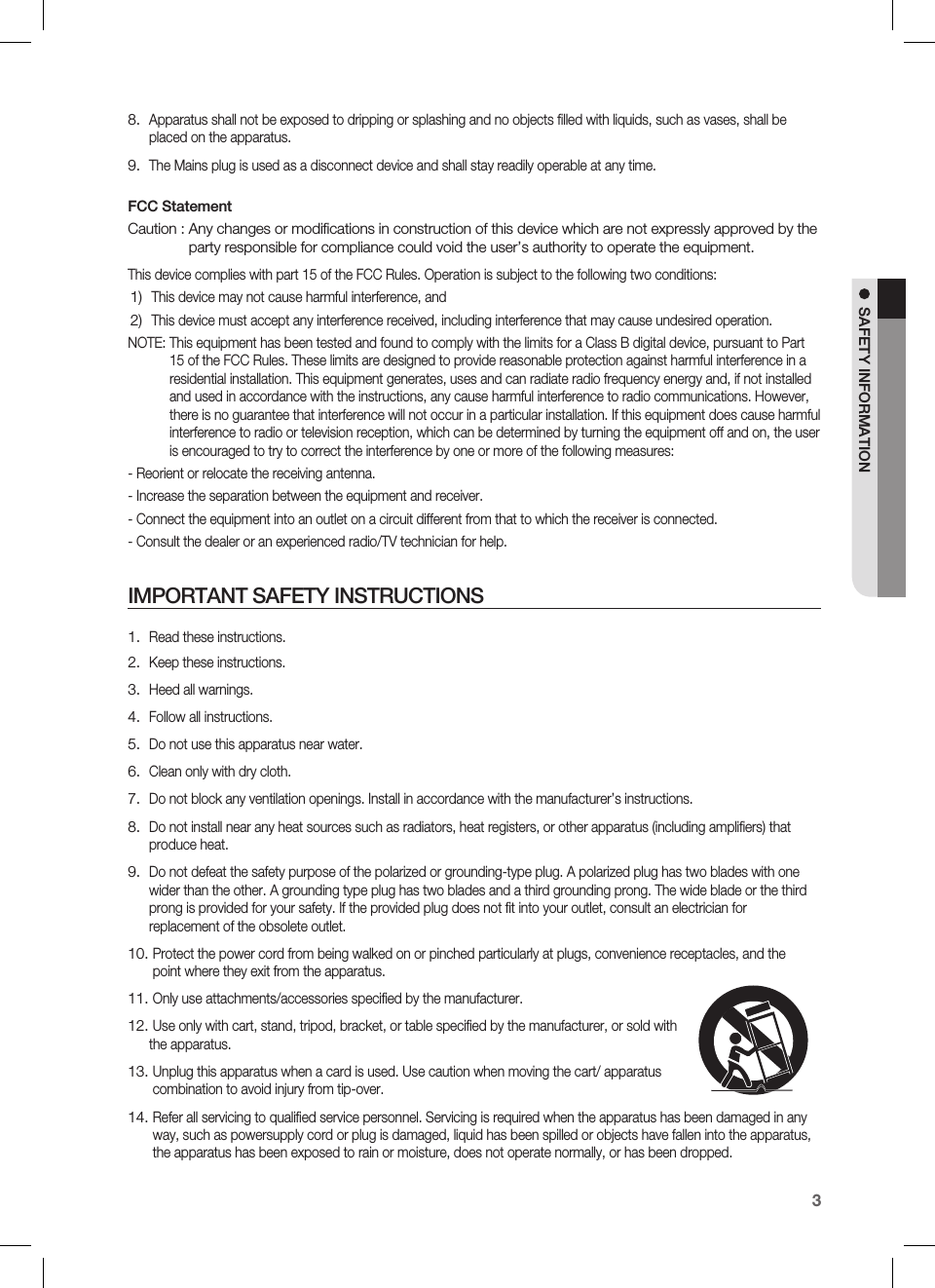
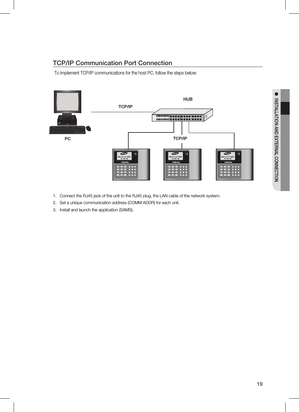
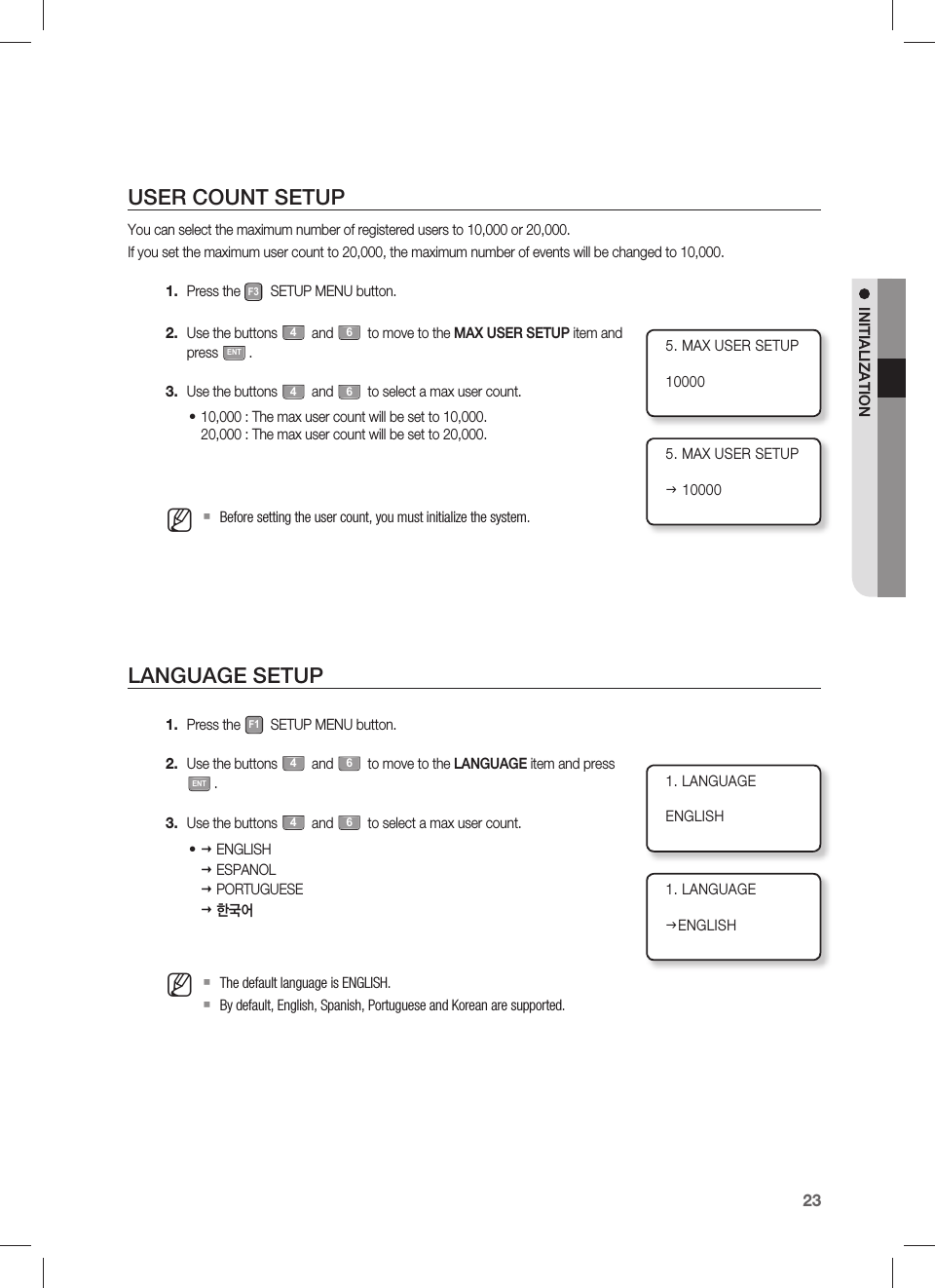
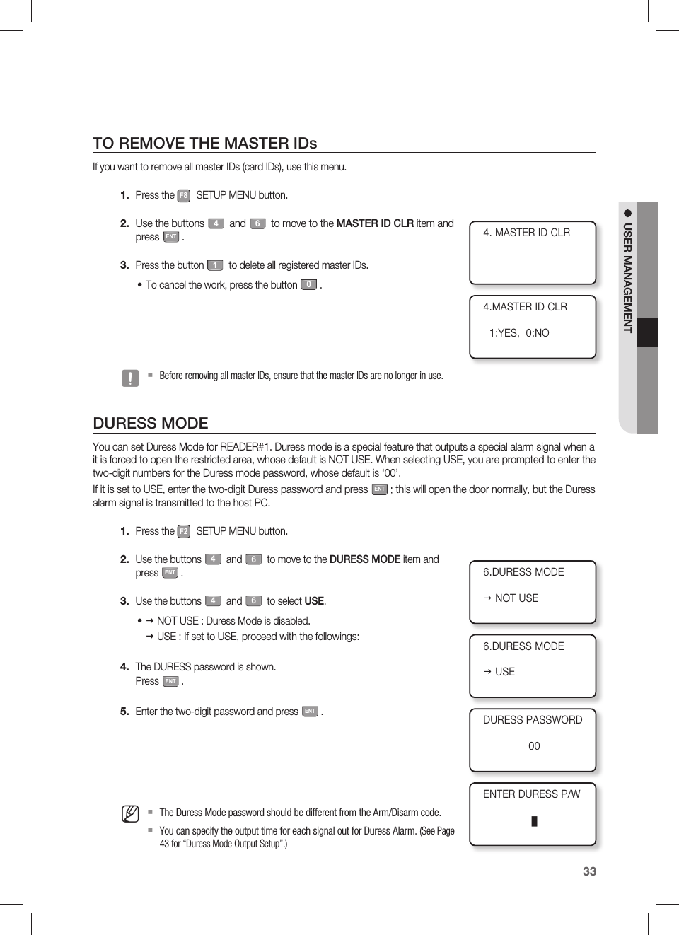
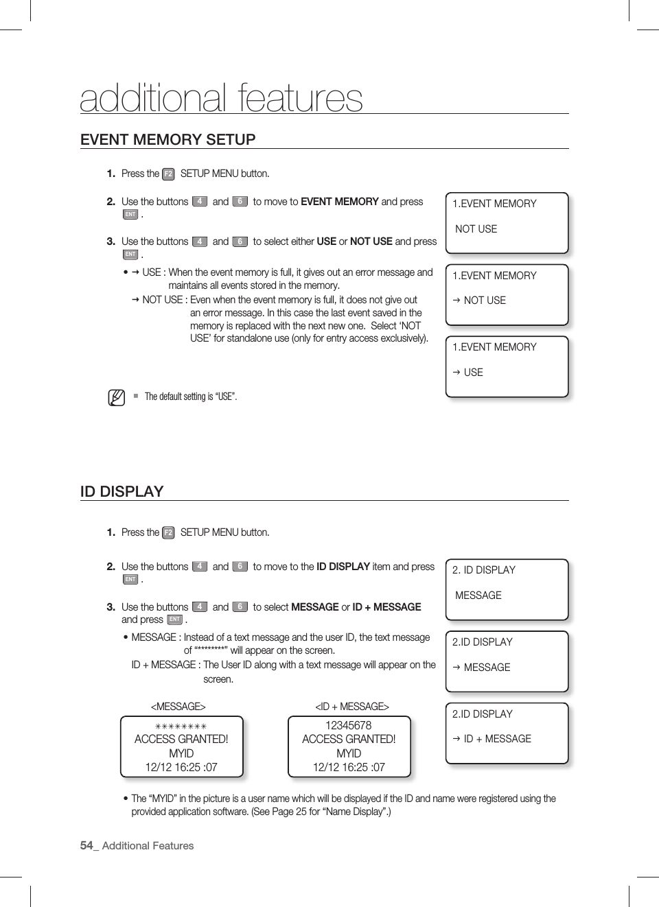
![English31USER MANAGEMENTTO DELETE IDA registered ID can be deleted by entering the ID using the card or keypad in ID DELETE mode.The number of the ID to delete will be displayed on the screen.Press the F7 SETUP MENU button.Use the buttons 4 and 6 to move to the ID DELETE item and press ENT.Enter the ID to delete, and press ENT.If you enter the card, you don’t need to press ENT.When the ID is deleted, you will see a message of “ID DELETED!!!” on the screen.If the entered ID is not registered with the product, you will see a message of “UNREGISTERED ID” on the screen.If an ID that is out of the acceptable range is entered , “INVALID NUMBER” message appears.The ID DELETE menu in QUICK MODE under [F12] is the same as ID DELETE under [F7].VIEWING THE ID LISTYou can check the list of IDs registered with the product.Press the F7 SETUP MENU button.Use the buttons 4 and 6 to move to the ID LIST item and press ENT.The list of registered IDs appears on the screen.The list of registered IDs appears on the screen.ID INDEX : Number of registered itemsID : ID numberC : ID permission codePW : passwordTA : Time schedule of READER #1TB : Time schedule of READER #2RD : Readers accessibleMA : Operation mode of READER #1MB : Operation mode of READER #2LV : Output levelUse the buttons 4 and 6 to check other registered IDs.The “EMPTY” message will appear if there is no user ID registered.The “FIRST ID” message indicates that the ID displayed on the screen is the fi rst one.The “LAST ID” message indicates that the ID displayed on the screen is the last one.1.2.3.•4.M1.2.3.•4.M2.ID DELETE2.ID DELETEENTER PINJ_ID DELETED!!!3.ID LISTID INDEX:00001ID:12300001 C:0PW0000 TA00 TB00RD0 MA0 MB0 LV1](https://usermanual.wiki/Samsung-Electronics-Co/SSAS2101/User-Guide-1192958-Page-31.png)

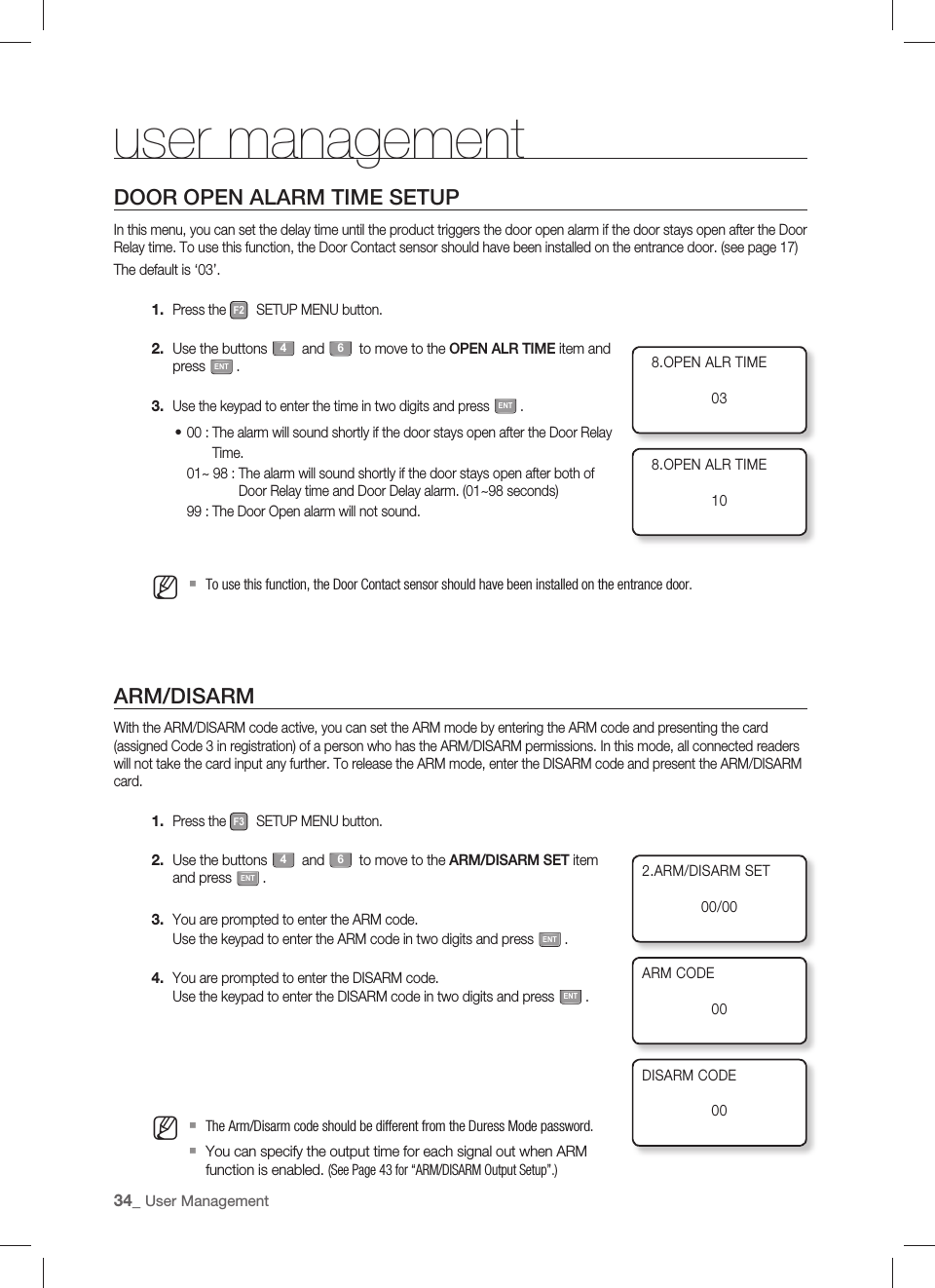
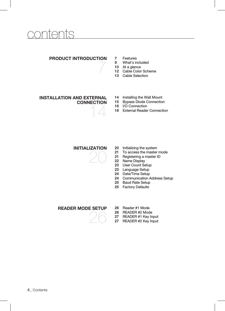
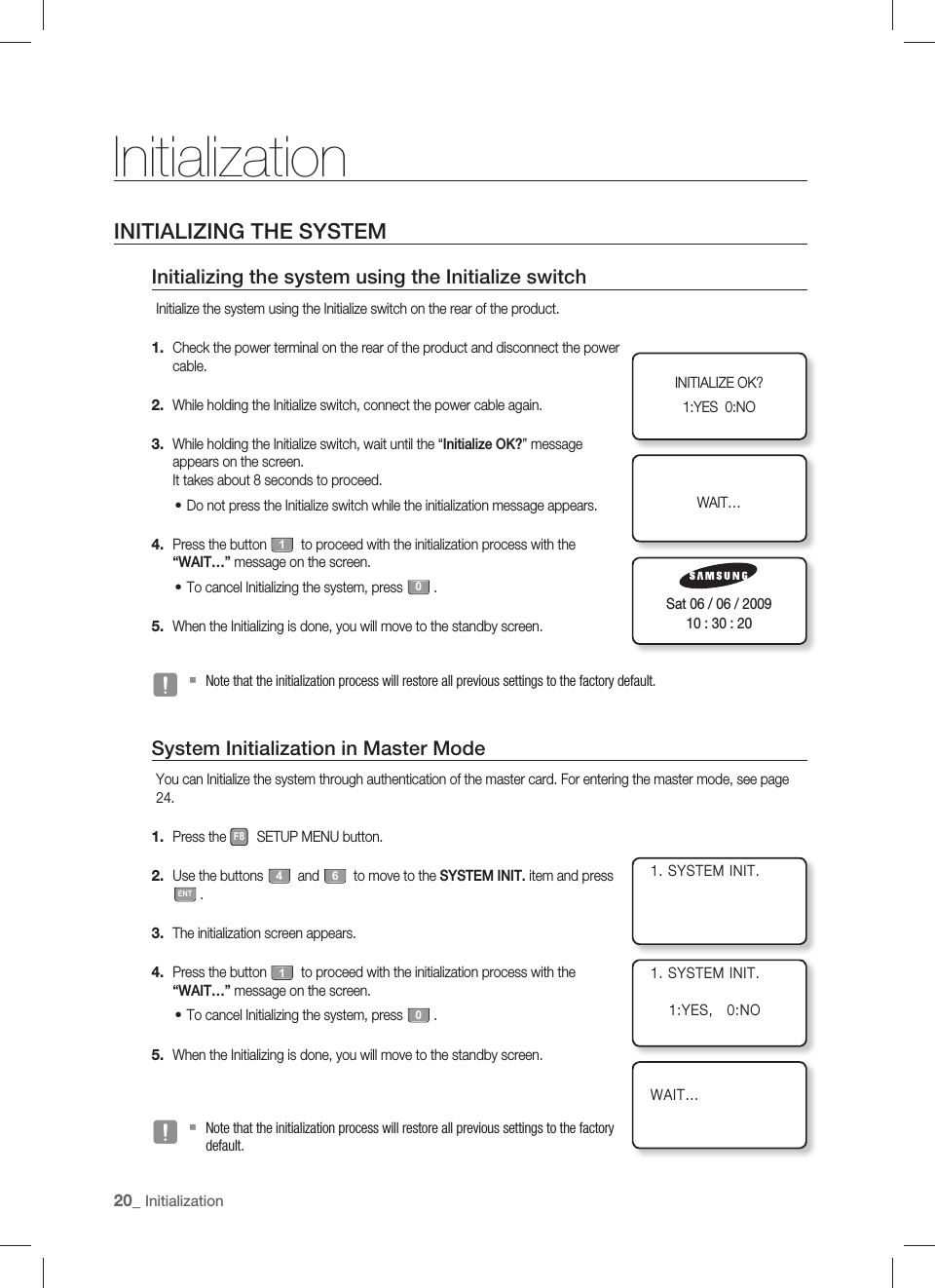
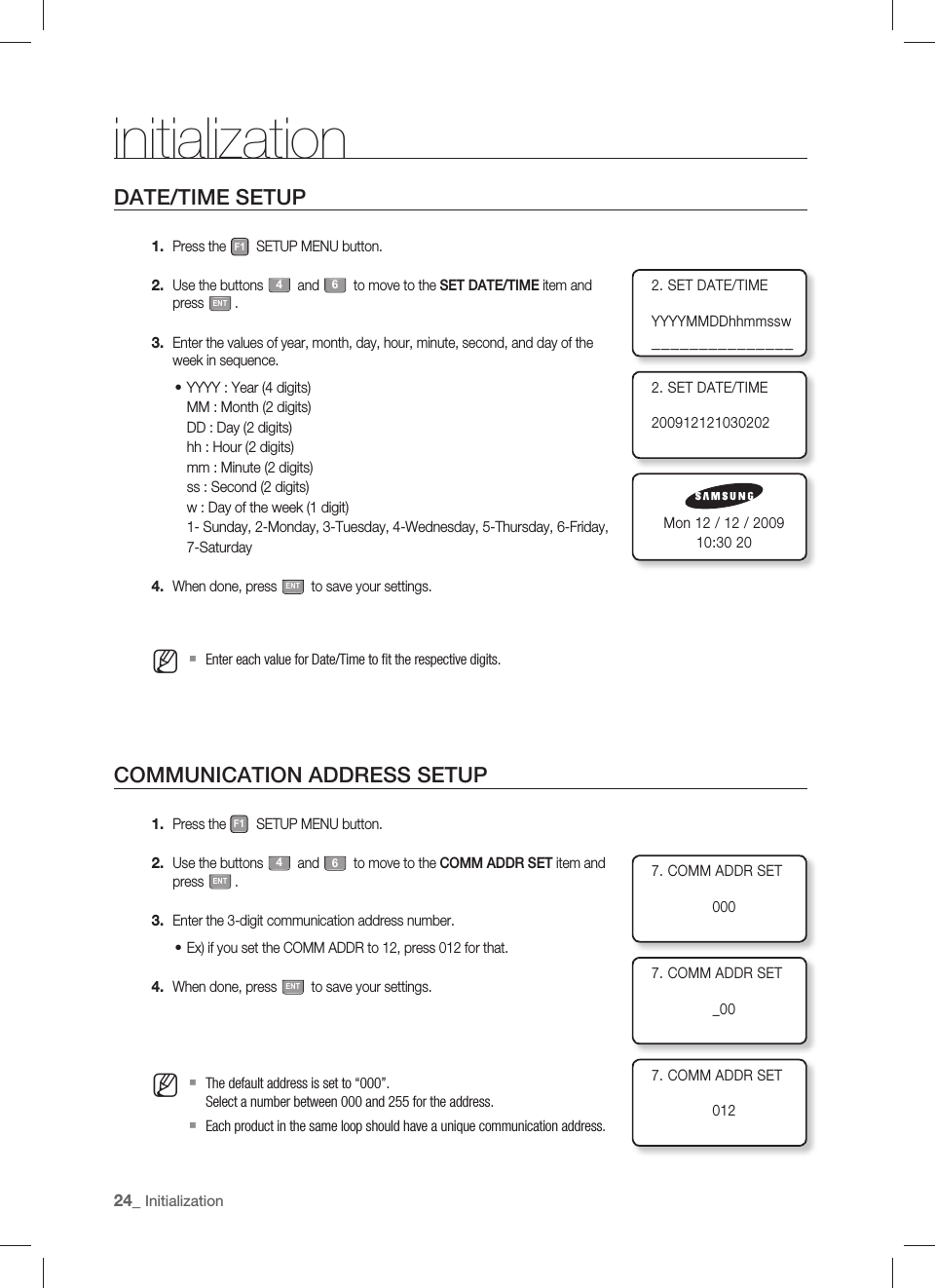
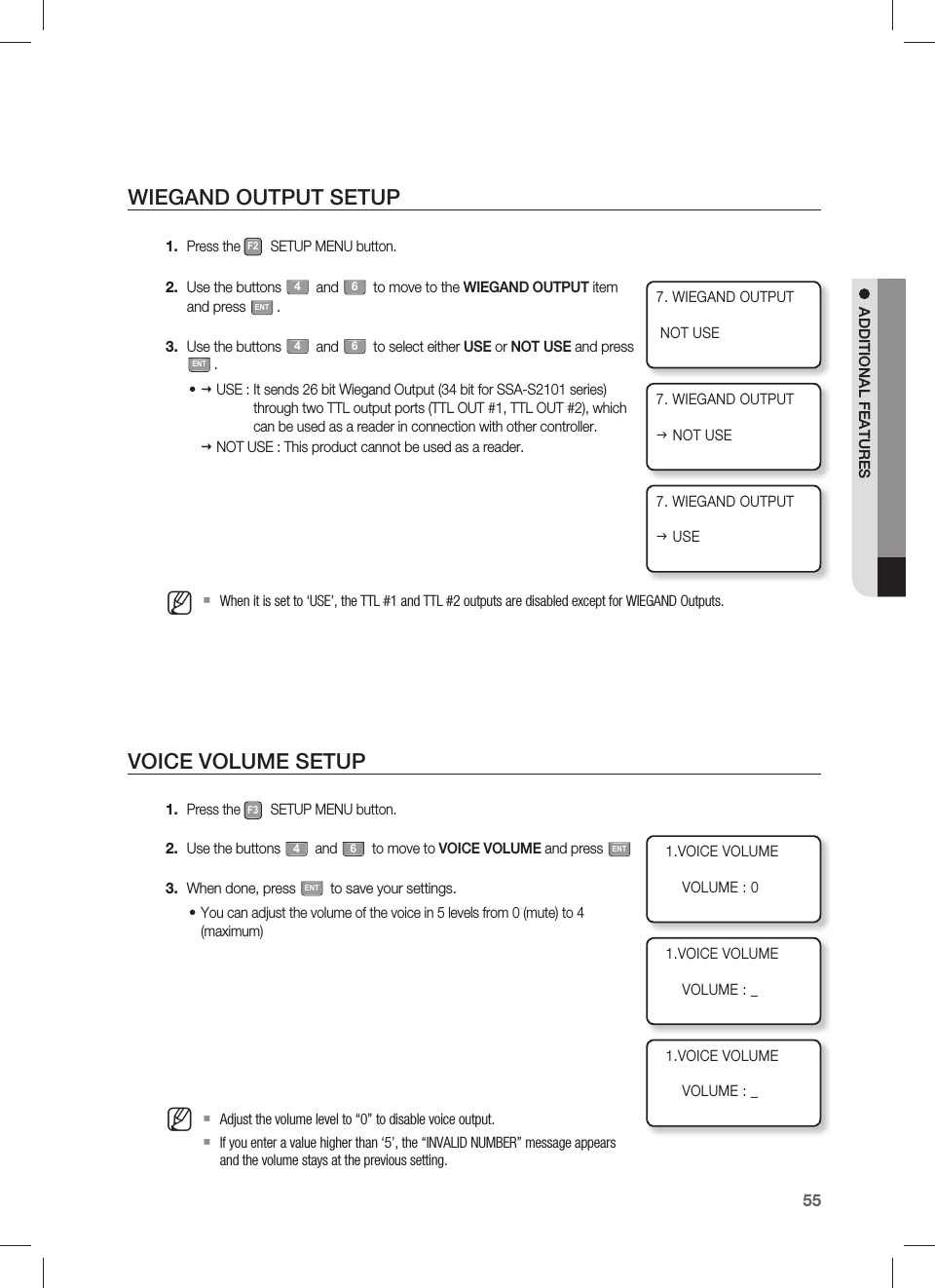
![English51ADVANCED SETUPREADER MODE TIME SCHEDULEREADER #1 MODE TIME SCHEDULEThere are 2 reader modes (in READER #1) including ID Mode and ID+PW Mode. Unless otherwise set specifi cally, all registered users should be verifi ed according to the reader mode in use. However you may allow entry with card only during a certain time interval for all users.For example, suppose you want to access the door by only presenting a card from 09:00 to 17:00 and use the password verifi cation method for the rest of the time. You can do so by setting [READER1 MODE SETTING] to ID+P/W mode which will be general operation mode, and program a time schedule code “01” so that it can include a time period between 09:00 and 17:00 for card access. And, link the programmed Time Schedule Code 01 to READER1 MODE Time Schedule setting.Press the F4 SETUP MENU button.Use the buttons 4 and 6 to move to the RD1 MODE T/S item and press ENT.Use the numeric buttons to enter 2-digit code and press ENT.T/S(Time Schedule) CODE : 00~10If the entry is incorrect, the “INVALID NUMBER” message will appear.The T/S Code “00” indicates no Time Schedule is to be applied. READER #2 Mode Time ScheduleThere are 2 reader modes (in READER #2) including ID Mode and ID+P/W Mode. Unless otherwise specifi ed, all registered users should be authenticated to the reader mode in use. However you may allow entry with card only during a certain time interval for all users.For example, suppose you want to access the door by only presenting a card from 09:00 to 17:00 and use the Fingerprint Verifi cation method for the rest of the time. And, you can do so by setting [READER2 MODE SETTING] to ID+P/W Mode which will be general operation mode, and program a T/S Code “01” so that it can include a time period between 09:00 and 17:00 for card access. And, link the programmed Time Schedule Code 01 to the READER2 MODE Time Schedule setting.Press the F4 SETUP MENU button.Use the buttons 4 and 6 to move to RD2 MODE T/S and press ENT.It can be confi gured in the same way as READER#1 Mode Time Schedule setting.1.2.3.•••1.2.•5.RD2 MODE I T/S004.RD1 MODE I T/S004.RD1 MODE I T/S10](https://usermanual.wiki/Samsung-Electronics-Co/SSAS2101/User-Guide-1192958-Page-51.png)
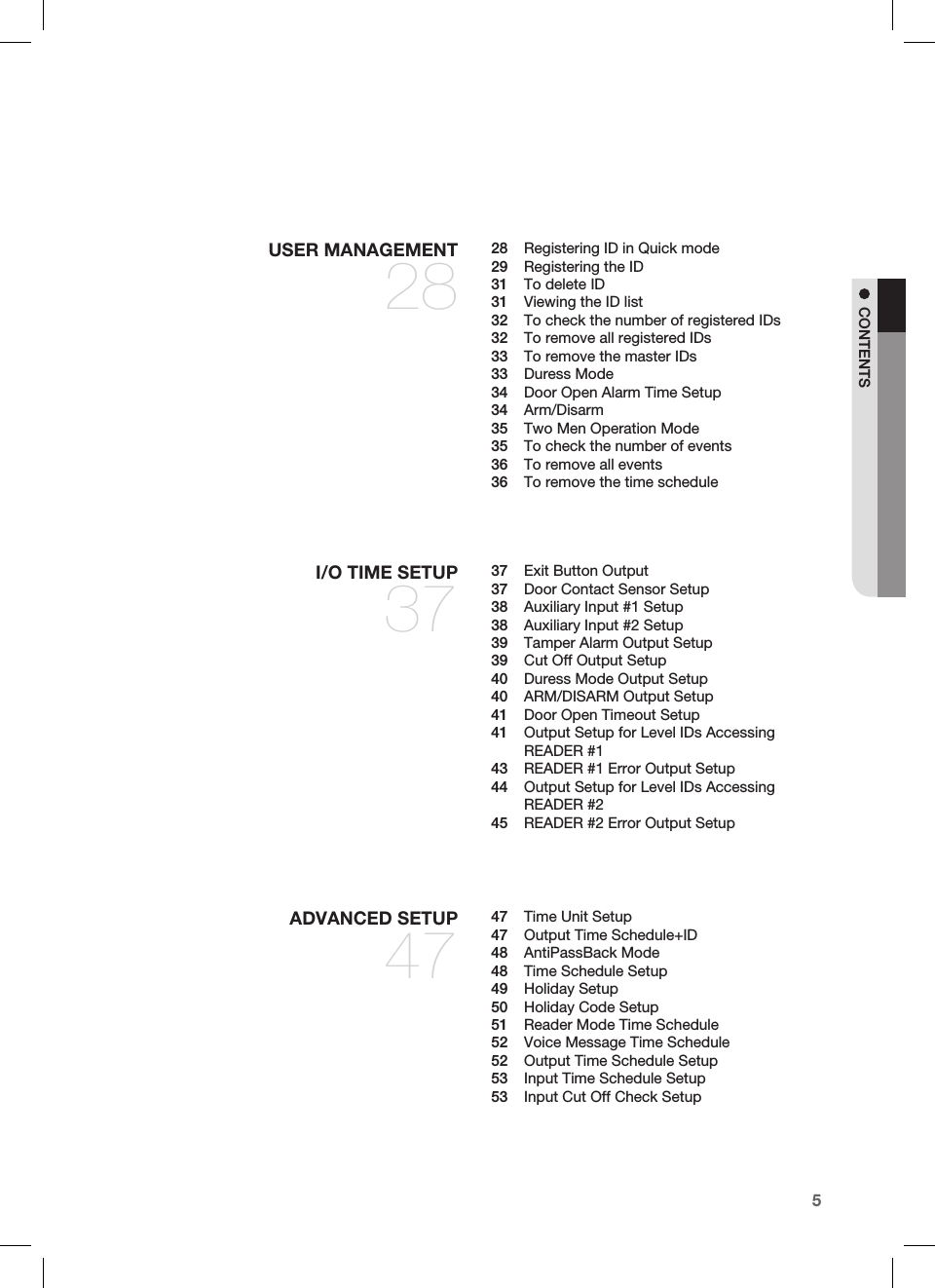
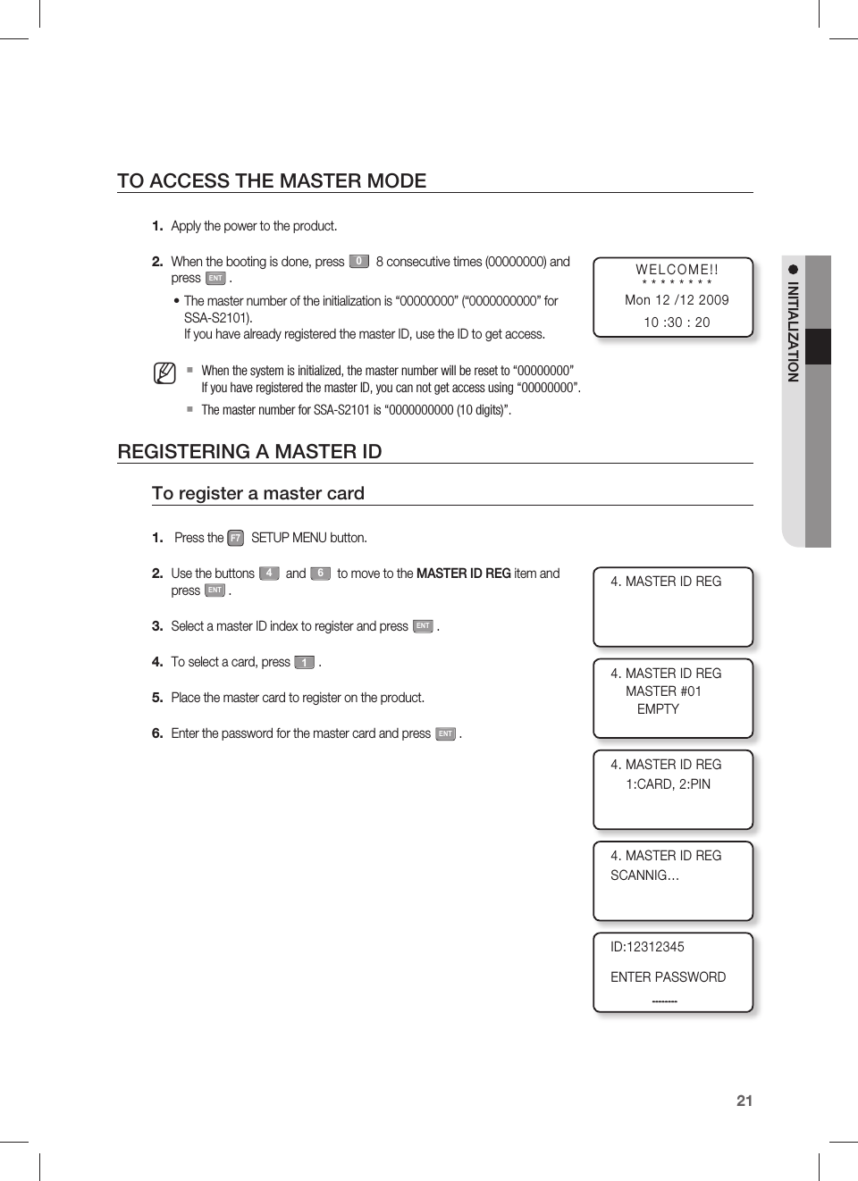
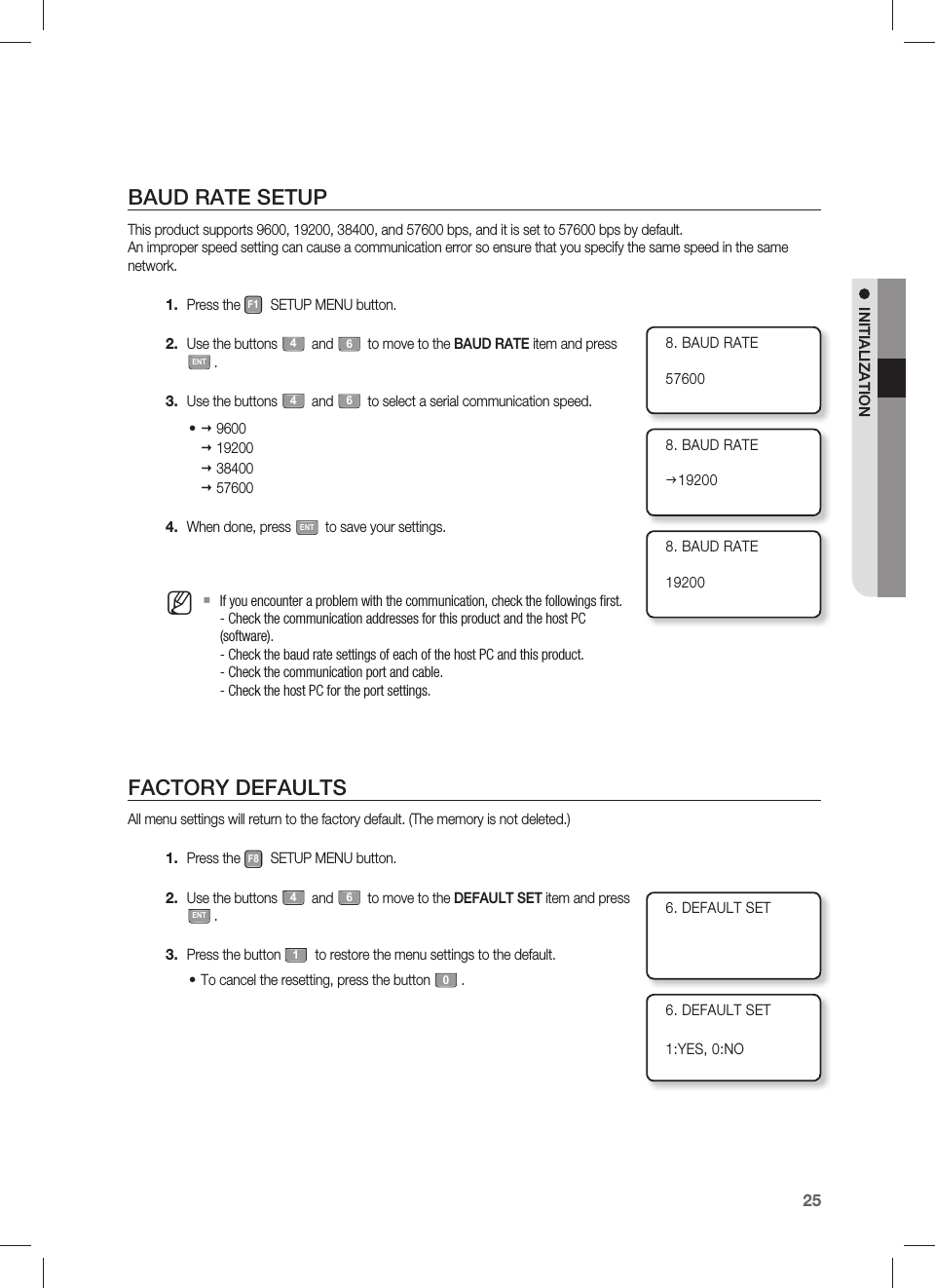
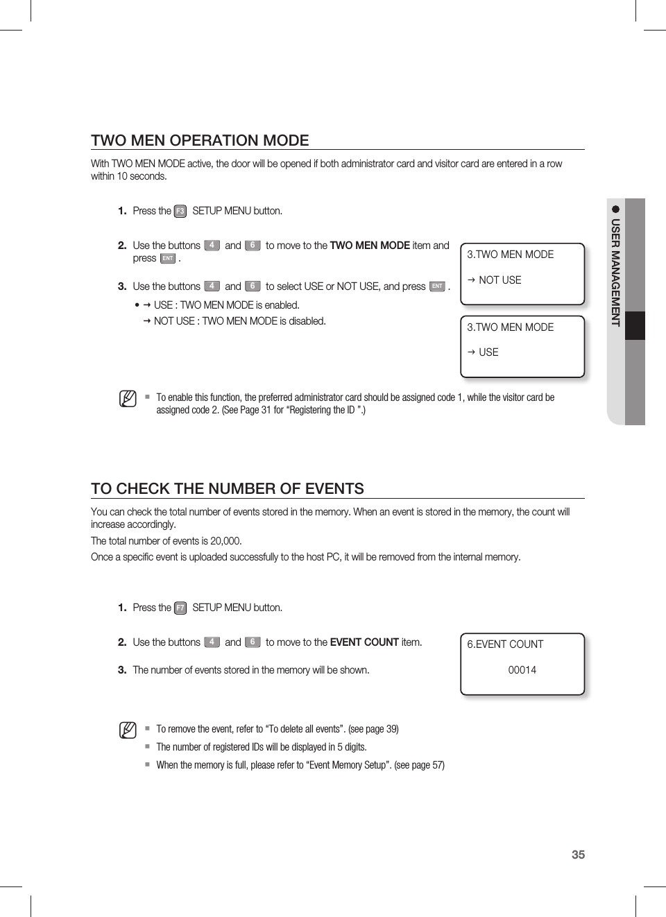
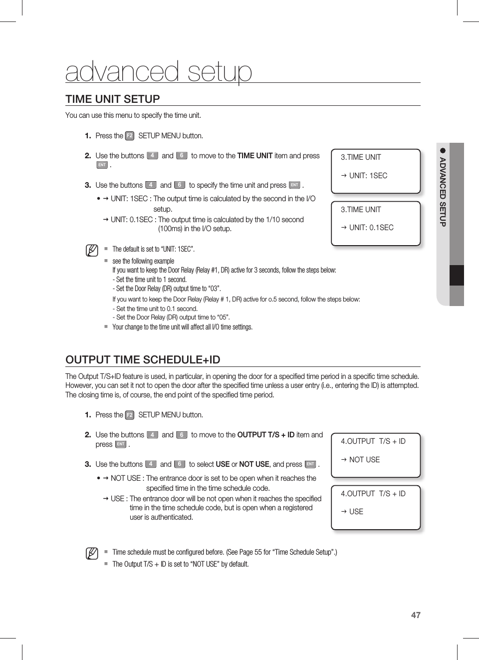
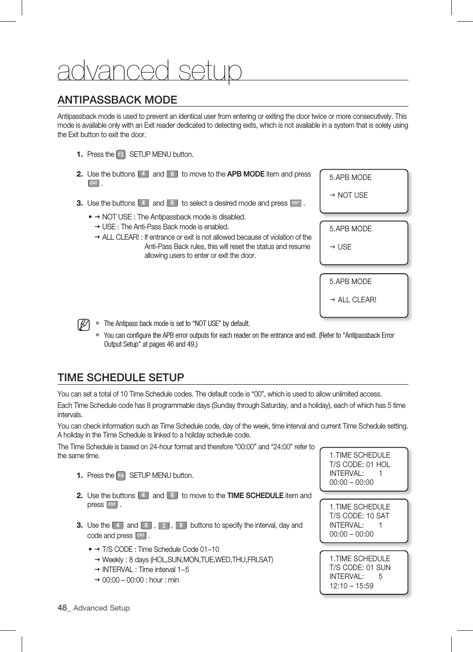
![62_ Other Informationother informationMENU STRUCTURE000~2559600192003840057600NOT USEUSENOT USEUSEENGLISH ESPANOLPORTUGUES한국어 ID ONLYID+P/WID ONLYID+PWF1 buttonLANGUAGESET DATE/ TIMEREADER #1 MODEREADER #2 MODERD#1 KEY INPUTRD#2 KEY INPUTCOMM ADDR SETBAUD RATE00~99NOT USEUSENOT USEUSENOT USEUSEALL CLEAR!UNIT : 1 SECUNIT : 0.1 SECMESSAGEID+ MESSAGEUSENOT USENOT USEUSEF2 buttonEVENT MEMORYID DISPLAYTIME UNITOUTPUT T/S + IDAPB MODEDURESS MODEWIEGAND OUTPUTOPEN ALR TIMEMenu Structure of the [F1] buttonYou can set Language, Date/Time and READER modes.Menu Structure of the [F2] buttonYou can set Event Memory, ID Display, Time Unit Setup, Output Time Schedule + ID, Antipassback Mode, Duress Mode, WIEGAND Output, and Door Open Timeout Alarm.](https://usermanual.wiki/Samsung-Electronics-Co/SSAS2101/User-Guide-1192958-Page-62.png)
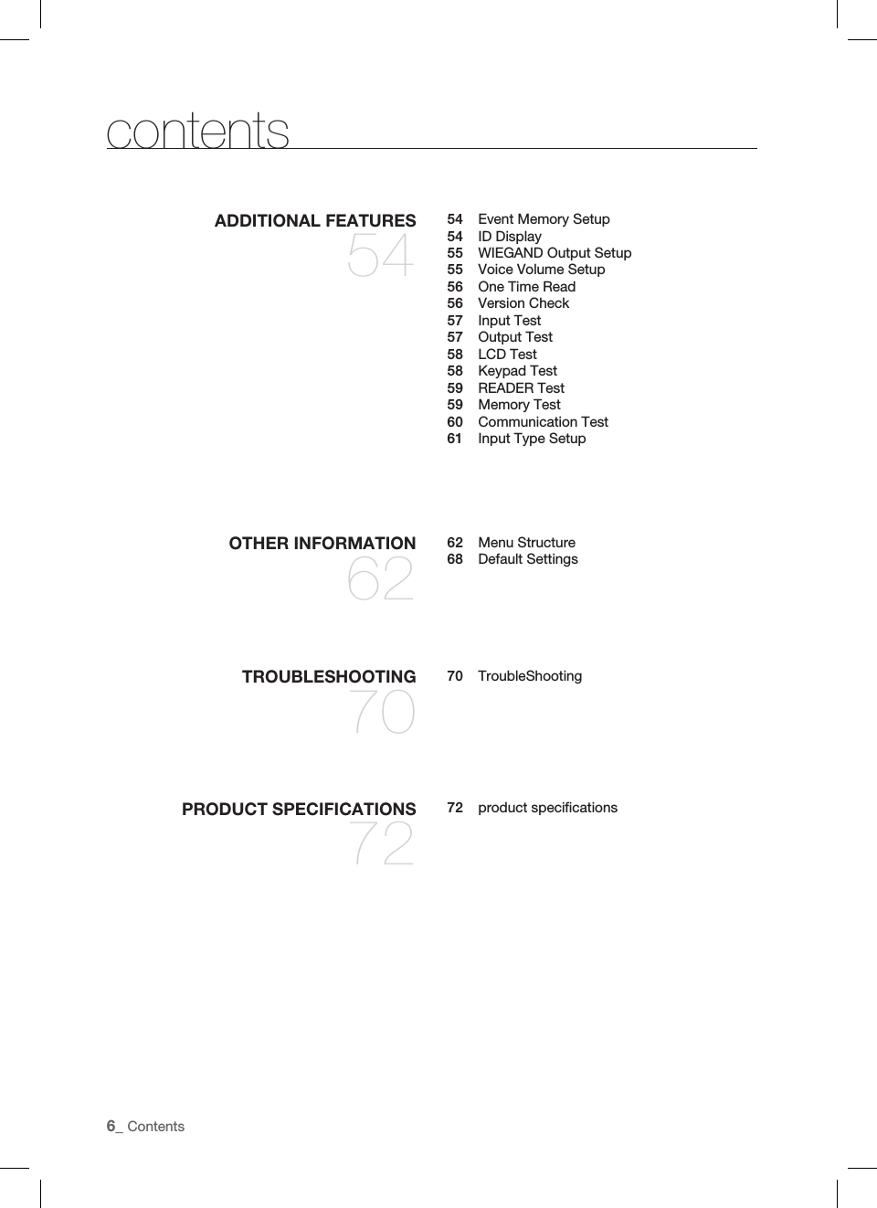
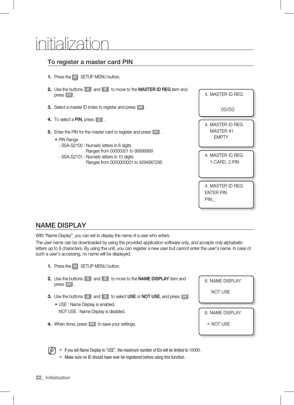
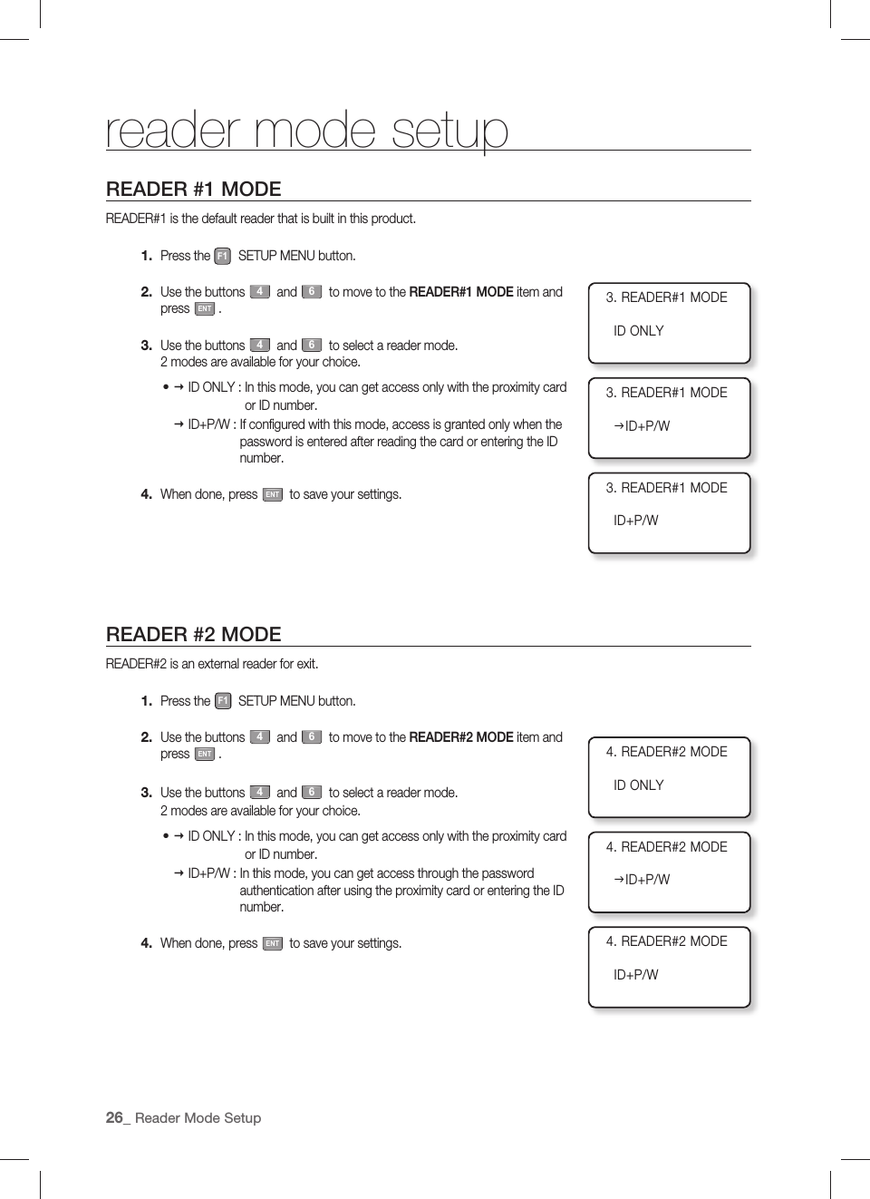
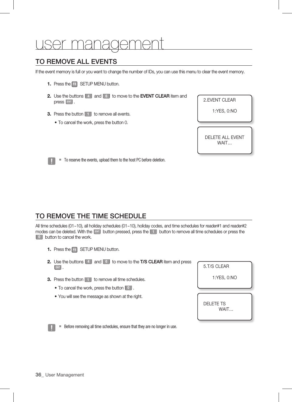
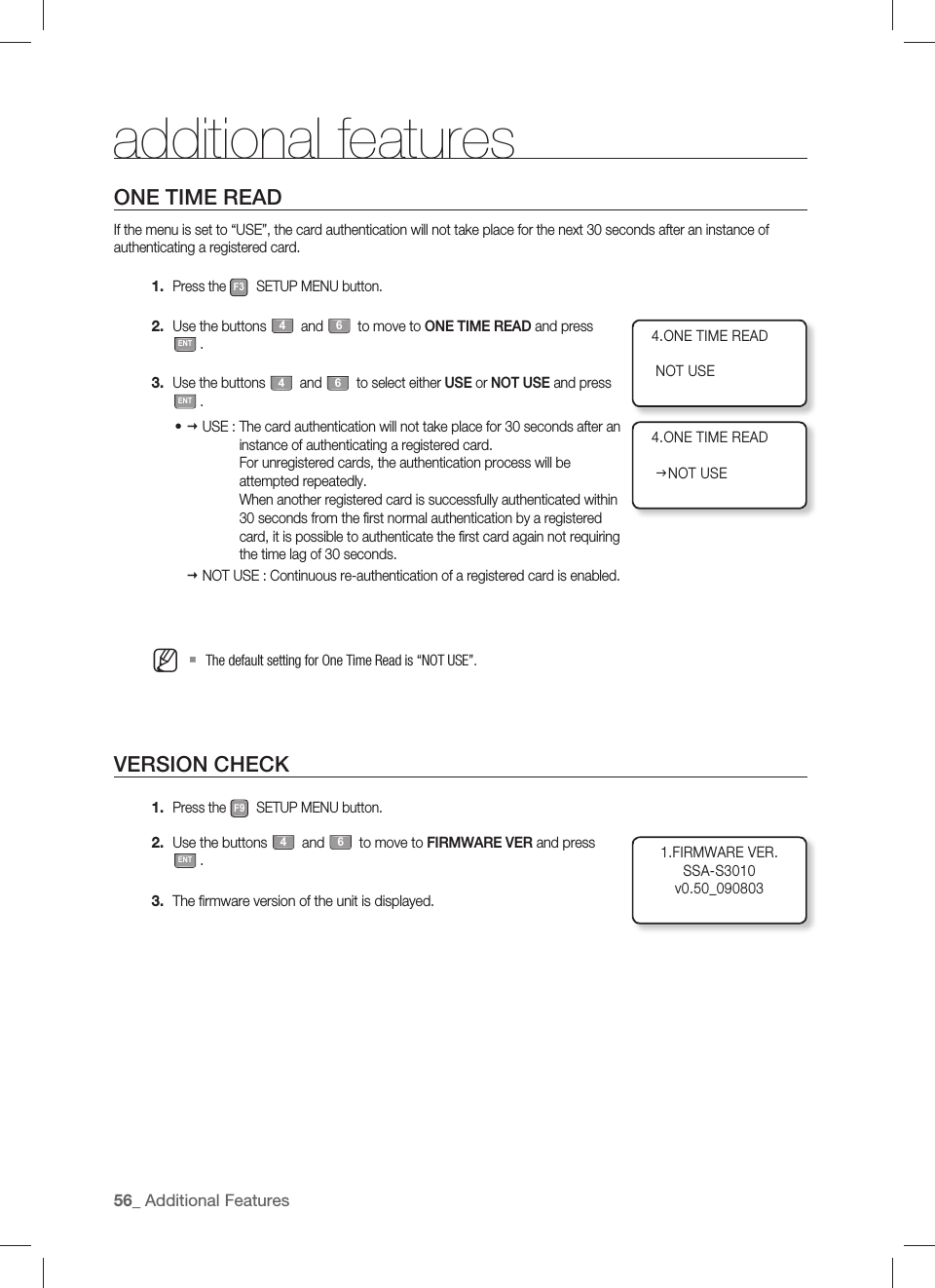
![English _63OTHER INFORMATIONNOT USEUSENOT USEUSE0 (MUTE) ~ 4 (MAXIMUM)10,00020,000NOT USEUSEF3 buttonVOICE VOLUMEARM/DISARMTWO MEN MODEONE TIME READMAX USER SETUPNAME DISPLAYT/S CODE : 01~10T/S CODE : 01~10T/S CODE : 01~10T/S CODE : 01~10Weekly INTERVAL : 1~5T/S CODE : 01~10HOLIDAY CODE : 01~10HOLIDAY CODE : 01~10DAY NO. : 001~100F4 buttonTIME SCHEDULEHOLIDAY SETHOLIDAY CODERD1 MODE T/SRD2 MODE T/SVOICE T/SMenu Structure of the [F3] buttonYou can set Voice Volume, Arm/Disarm, Two Men Operation, One Time Read, Number of Users, and Name Display.Menu Structure of the [F4] buttonYou can set Time Schedule, Holiday, Holiday Code, READER #1 and #2 Mode Time Schedule, and Voice Message Time Schedule.](https://usermanual.wiki/Samsung-Electronics-Co/SSAS2101/User-Guide-1192958-Page-63.png)
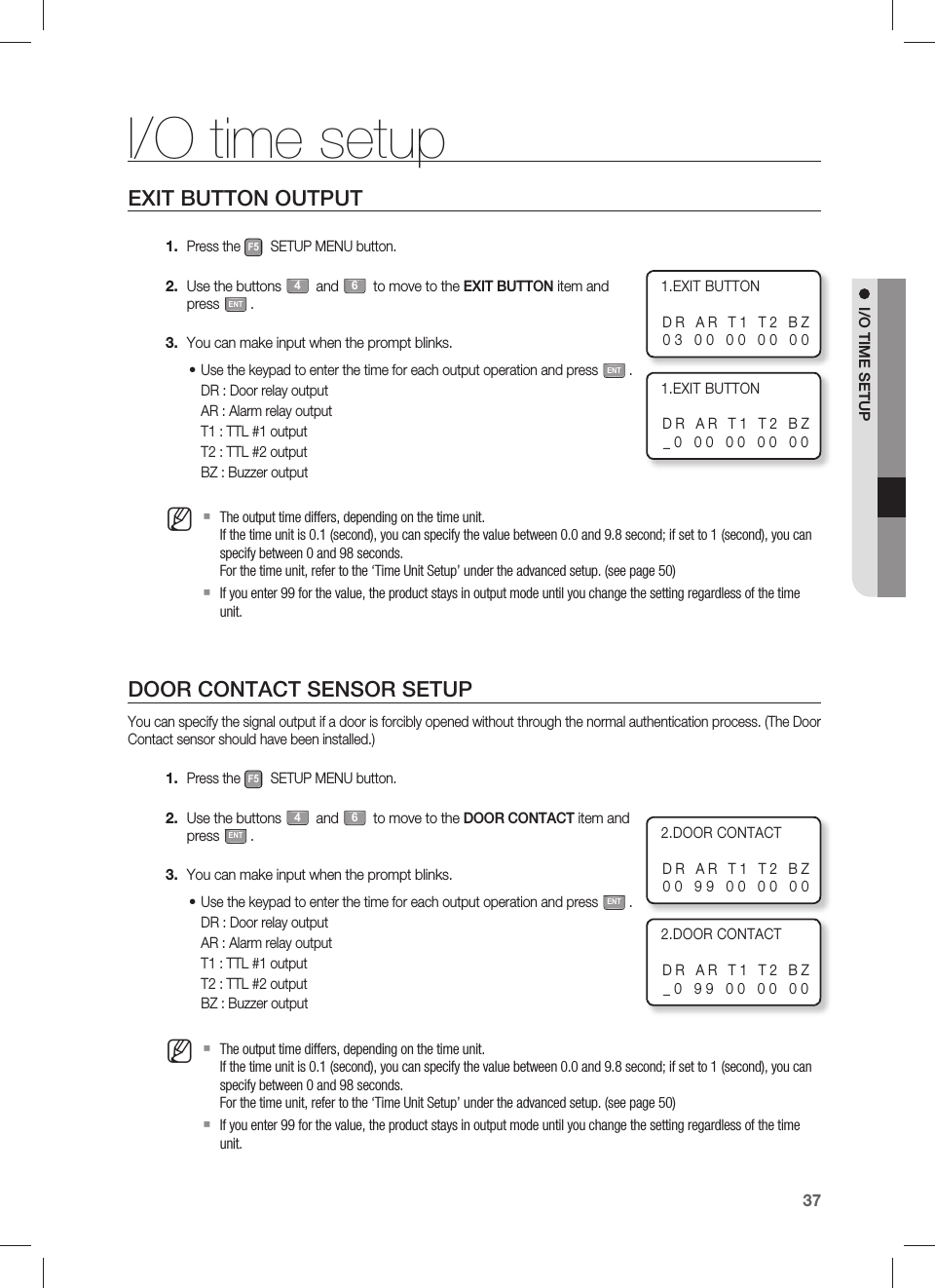
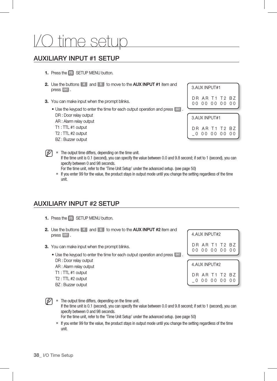
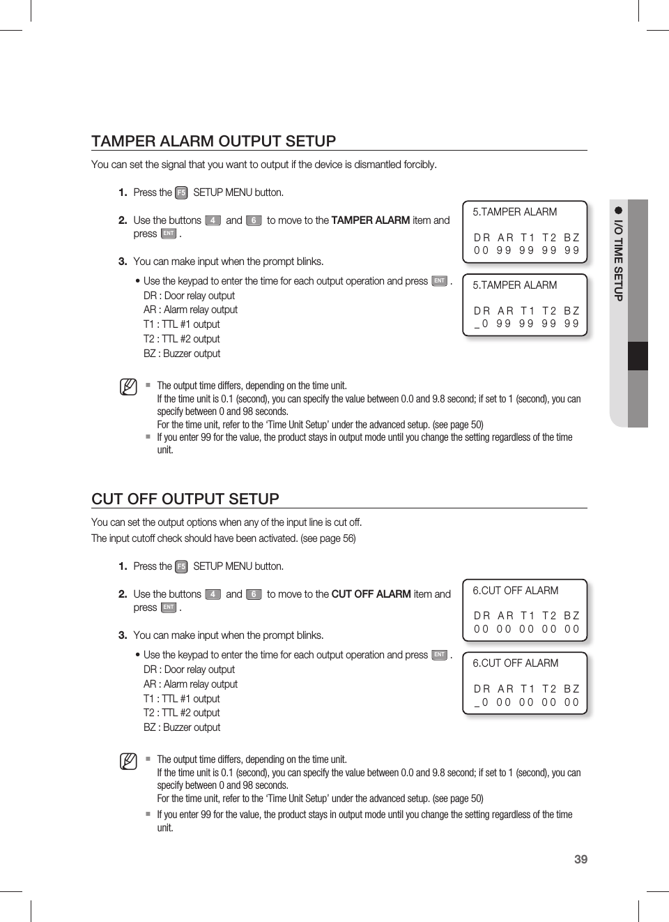
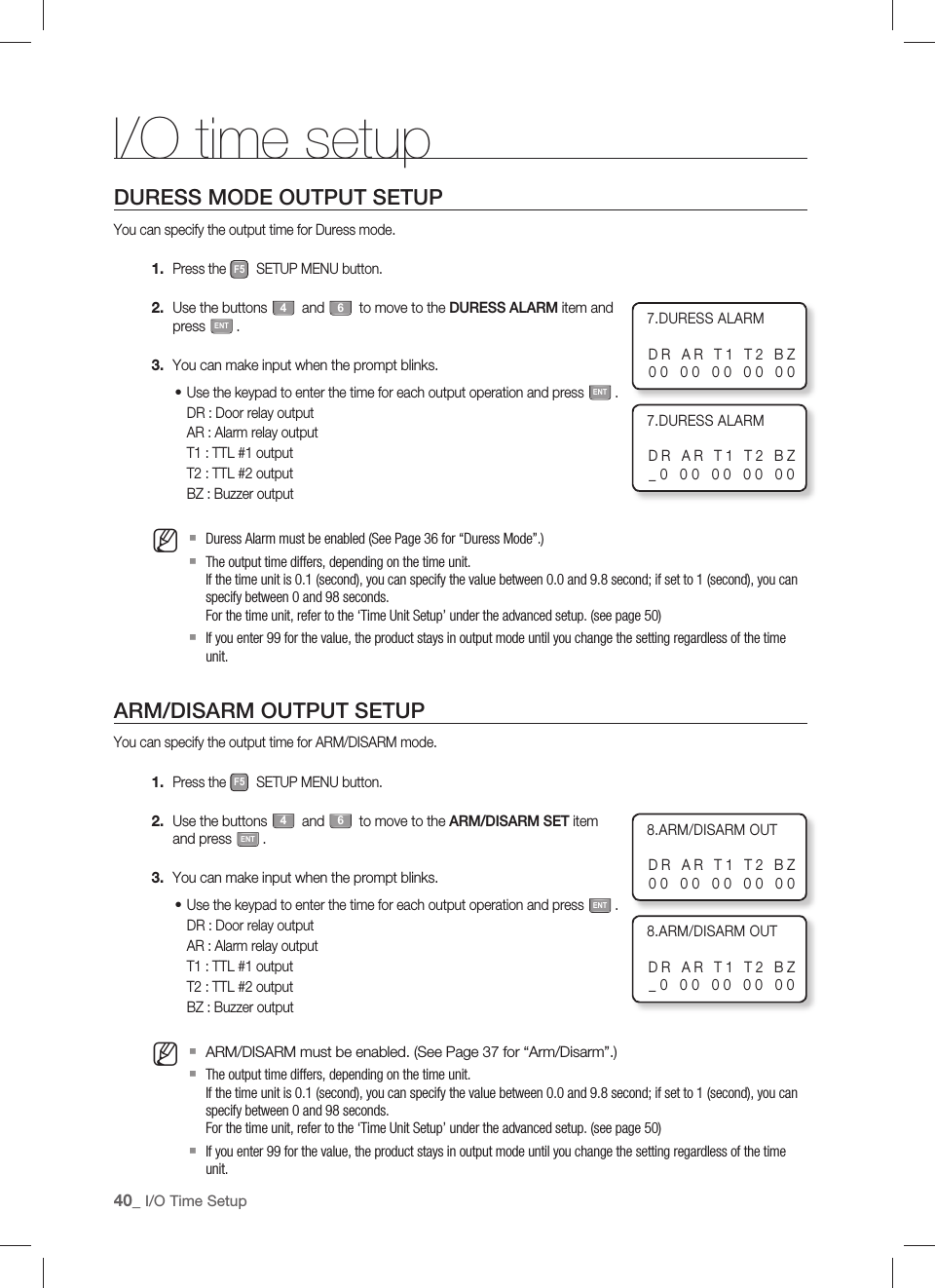
![other information64_ Other InformationF5 buttonEXIT BUTTONDOOR CONTACTAUX INPUT #1AUX INPUT #2TAMPER ALARMCUT OFF ALARMDURESS ALARMARM/DISARM OUTDOOR TIME OUTOUTPUT T/SINPUT T/SCUT OFF SETINPUT TYPEMenu Structure of the [F5] buttonYou can set Exit Key Output, Door Contact Sensor, Aux Input #1 and #2, Tamper Alarm Output, Cut Off Output, Duress Alarm Output, Arm/Disarm Output, Door Open timeout Output, Input/Output Time Schedule, Input Cut Off Check, and Input Type.](https://usermanual.wiki/Samsung-Electronics-Co/SSAS2101/User-Guide-1192958-Page-64.png)
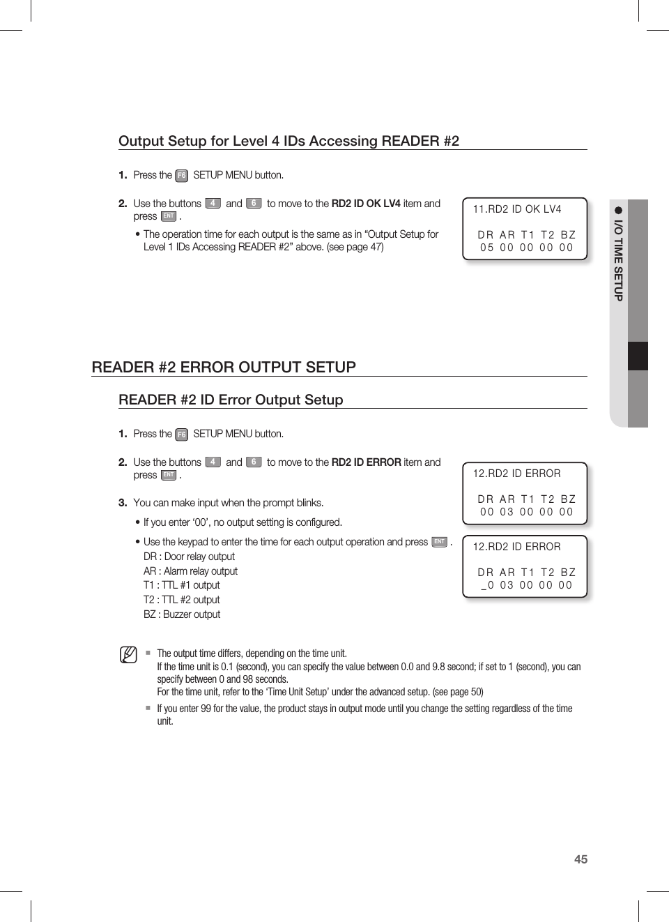
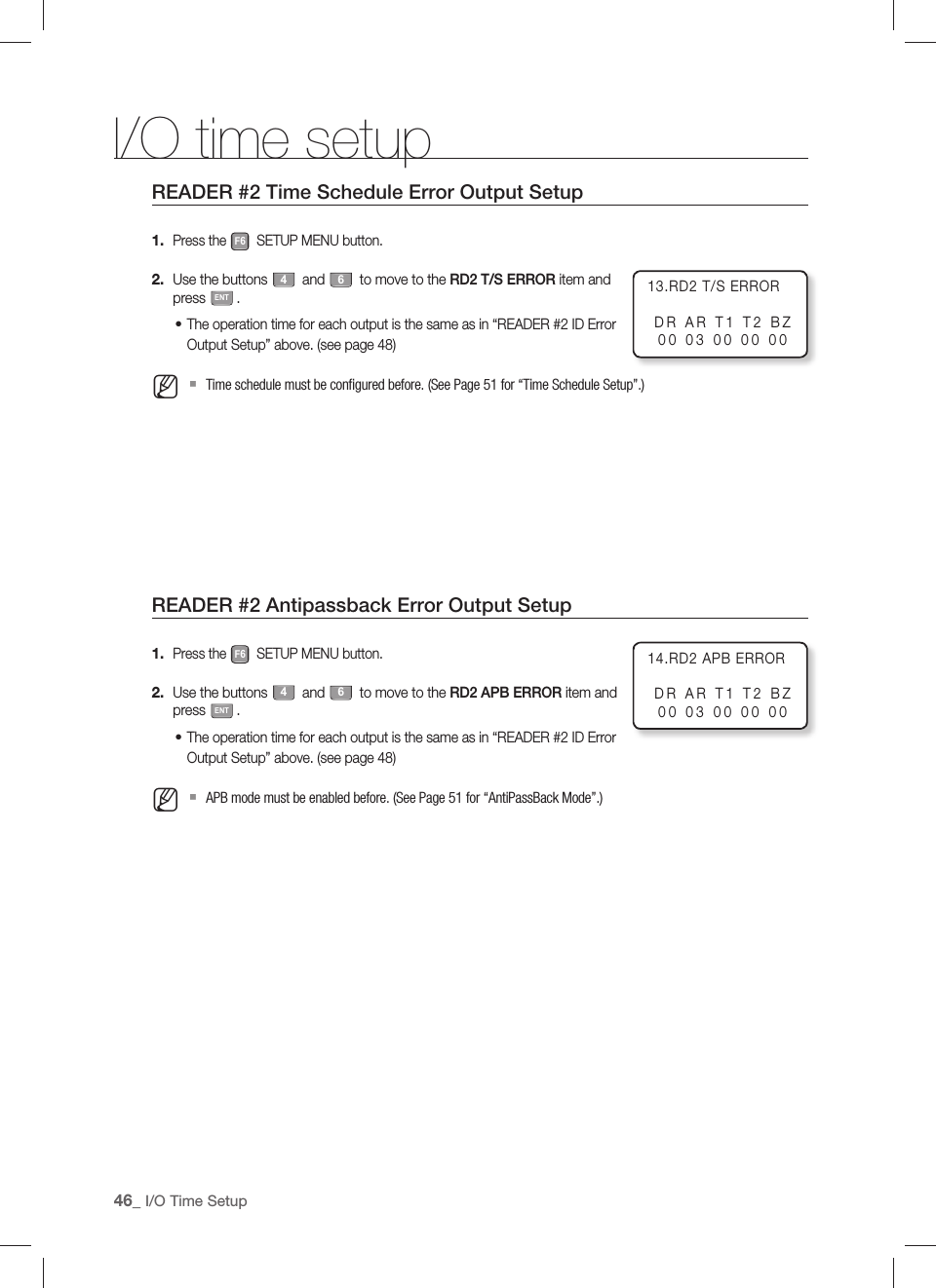
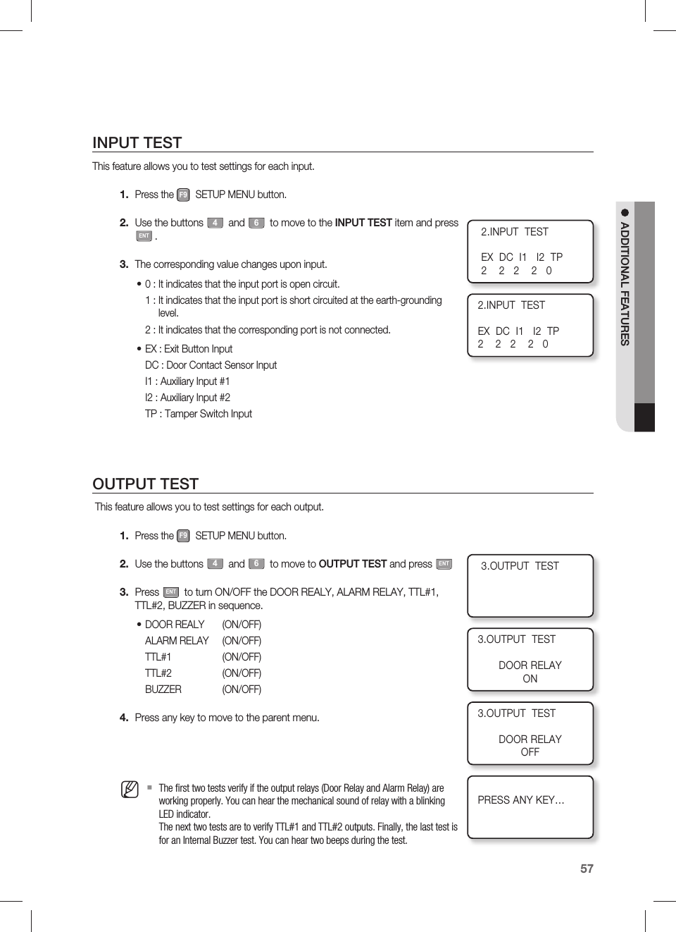
![English _65OTHER INFORMATIONF6 buttonRD1 ID OK LV1RD1 ID OK LV2RD1 ID OK LV3RD1 ID OK LV4RD1 ID ERRORRD1 T/S ERRORRD2 ID OK LV1RD2 ID OK LV2RD2 ID OK LV3RD2 ID OK LV4RD2 ID ERRORRD2 T/S ERRORRD2 APB ERRORRD1 APB ERRORMenu Structure of the [F6] buttonYou can set Output for Accessible levels for READER #1 and #2 ID, READER #1 and #2 ID Error Output, READER #1 and #2 Time Schedule Error Output, READER #1 and #2 Antipassback Error Output.](https://usermanual.wiki/Samsung-Electronics-Co/SSAS2101/User-Guide-1192958-Page-65.png)
![other information66_ Other InformationYESNOYESNOYESNOYESNOYESNOYESNOF8 buttonSYSTEM INIT.EVENT CLEARALL ID CLEARMASTER ID CLRT/S CLEARDEFAULT SETCARDKEYF7 buttonREGISTRATIONID DELETEID LISTMASTER ID REGREG. ID COUNTEVENT COUNTMenu Structure of the [F7] buttonYou can register or delete IDs and register the master ID. You can also view the ID list, ID count and event count.Menu Structure of the [F8] buttonYou can initialize the master mode and delete the entire events, IDs, Master ID and Time Schedules.](https://usermanual.wiki/Samsung-Electronics-Co/SSAS2101/User-Guide-1192958-Page-66.png)
![English _67OTHER INFORMATIONF9 buttonFIRMWARE VERINPUT TESTOUTPUT TESTLCD TESTKEYPAD TESTREADER TESTMEMORY TESTCOMM TEST Menu Structure of the [F9] buttonYou can check the system version. You can also test the input, output, LCD, keypad, reader, memory and communication status.Menu Structure of the [F12] buttonYou can easily register or delete IDs without going through a complex setup procedure.F12 button(QUICK MODE) REGISTRATION(QUICK MODE) ID DELETE](https://usermanual.wiki/Samsung-Electronics-Co/SSAS2101/User-Guide-1192958-Page-67.png)
![other information68_ Other InformationDEFAULT SETTINGSOutput Settings for Input SourcesOutputInputDoor Relay (DR)Alarm Relay(AR)TTL#1(T1)TTL#2(T2)Buzzer(BZ)[1] Exit Button 03 00 00 00 00[2] Door Contact 00 99 00 00 00[3] AUX Input #1 00 00 00 00 00[4] AUX Input #2 00 00 00 00 00[5] TAMPER Alarm 00 99 99 99 99[6] Cut Off Alarm 00 00 00 00 00[7] DURESS ALARM 00 00 00 00 00[8] ARM/DISARM OUT00 00 00 00 00[9] Door Open Timeout 00 99 00 00 00[10] Output Time Schedule 00 00 00 00 00[11] Input Time Schedule 00 00 00 00 00[12] Cut Off Check 00 00 00 00 00[13] Input Type 00 00 00 00 00Index No. [1] ~ [9] The values indicate the operating time of each output for the input signal.Index No. [10] The values indicate the time schedule code (index) applied to each output.Index No. [11] The values indicate the input port ([1]Exit Button ~ [5]Tamper S/W).Each value indicates the code of Time Schedule to be applied to the corresponding input port.Index No. [12] The values indicate whether or not to use the cut off check feature for each input. (0 – Not Use, 1 – Use)Index No. [13] The values indicate whether the input type is NO(Normally Open) or NC(Normally Closed). (0 – NO, 1 – NC)1)2)3)4)5)](https://usermanual.wiki/Samsung-Electronics-Co/SSAS2101/User-Guide-1192958-Page-68.png)
![English _69OTHER INFORMATIONOutput Setting for AuthenticationOutputInputDoor Relay (DR)Alarm Relay(AR)TTL#1(T1)TTL#2(T2)Buzzer(BZ)[1] Reader#1 ID OK LV1 03 00 00 00 00[2] Reader#1 ID OK LV2 05 00 00 00 00[3] Reader#1 ID OK LV3 05 00 00 00 00[4] Reader#1 ID OK LV4 05 00 00 00 00[5] Reader#1 ID Error 00 03 00 00 00[6] Reader#1 T/S Error 00 03 00 00 00[7] Reader#1 APB Error 00 03 00 00 00[8] Reader#2 ID OK LV103 00 00 00 00[9] Reader#2 ID OK LV2 05 00 00 00 00[10] Reader#2 ID OK LV3 05 00 00 00 00[11] Reader#2 ID OK LV4 05 00 00 00 00[12] Reader#2 ID Error 00 03 00 00 00[13] Reader#2 T/S Error 00 03 00 00 00[14] Reader#2 APB Error 00 03 00 00 00Index No. [1] ~ [14] The values indicate the operating time of each output for the input signal.1)](https://usermanual.wiki/Samsung-Electronics-Co/SSAS2101/User-Guide-1192958-Page-69.png)
![70_ troubleshootingtroubleshootingTROUBLESHOOTINGIf the product does not function properly, please see the below for trouble shooting. If the trouble persists, please contact the SAMSUNG Customer Service near you.PROBLEM SOLUTIONA valid card that had been in use became unregistered after batch-downloading IDs from a PC.1) The card ID might be registered only to the controller and not to the PC. During the process of batch-downloading IDs from the PC, the PC fi rst erases the ID memory in the unit and rewrites from the beginning. This trouble can happen if those IDs were not registered on the PC at the point of batch-downloading.2) Check whether the card ID is registered on the PC or not.3) If not, please register the card ID and try again.4) If the trouble persists after following the procedures above, contact a designated service center.I entered the Master ID “00000000” but I still cannot enter the Setup Mode(“0000000000” for SSA-S2101)1) Try changing the Master ID using the application software. (The Master ID will be changed to the value of your choice.)2) If the product does not function properly, follow the steps below to initialize the system : After the installation and connections are completed, press the initialize button and apply power (+12V DC) to turn on the product. You will see the “Initialize OK?0:No 1: Yes” message on the screen.Press the button 1 if you want to initialize the system.After all the initialization process is completed, the system will be operating on the normal mode and the screen will display the SAMSUNG logo, Date and Time information.3) If the trouble persists after following the procedures above, contact a designated service center.No problem with accessing by card, but cannot access via a manual PIN input.1) Check whether a beep sounds when you press a key.If a beep sounds, the problem may be wrong settings.Proceed as followings: - Enter the Master ID (Default=“00000000”) to get into the Setup mode. (“0000000000” for SSA-S2101) - Press the F1 button. - Select ‘USE’ in the [RD#1 KEY INPUT] on the screen. 2) When there is no beep sound or the problem persists after the [RD#1 KEY INPUT] has been set to ‘USE’, contact a designated service center.The unit suddenly returns to the normal operating mode.The unit is originally programmed to go back to the normal operating mode when no buttons are pressed or no cards are read within 60 seconds in the setup mode.•The “SCHEDULE ERROR” message appears when a RFID card is being read.1) If the unit used to be properly operating before, it is likely that there has been an electric shock that damaged the internal memory and data. Please initialize the unit as instructed in the manual.2) Check if the ID information has been confi gured correctly. - Check if the Time Schedule is set to the time of your choice. - Check if the values for TA and TB are set correctly to the Time Schedule of your choice during the ID registration.3) If this unit is connected to a PC software, use the software that allows easy settings.4) If the trouble persists after following the procedures above, contact a designated service center.](https://usermanual.wiki/Samsung-Electronics-Co/SSAS2101/User-Guide-1192958-Page-70.png)
![English _71TROUBLE SHOOTINGPROBLEM SOLUTIONThe “ACCESS DOOR ERR” message appears when a RF ID card is being read.1) 1) If the unit used to operate properly before, it is likely that there has been an electric shock that damaged the internal memory and data. Please initialize the unit as instructed in the manual.2) Check if the ID information has been entered correctly during its registration. - Check if the value for RD is set correctly during the ID registration. - If the RD value is set to “1”, the door opens only when READER 1 reads tthe card, and does not open when READER 2 reads the card. If the card is presented to READER 2, the “ACCESS DOOR ERROR” message will appear. - If the RD value is set to “2”, the door opens only when READER 2 reads the card, and does not open when READER 1 reads tthe card. If the card is presented to READER 1, the “ACCESS DOOR ERROR” message will appear. - If the RD value is set to either “0” or “3”, the door opens when either READER 1 or 2 reads the card.3) If the trouble persists after following the procedures above, contact a designated service center.The buzzer keeps beeping.1) Check the door status. If the Door Contact sensor is connected and the Door Open Timeout Alarm is selected, an alarm is given.2) Check the Door Contact sensor type: it must be NO/NC-type.3) Check the setup value for BZ in [10. OUTPUT T/S] under the [F5] menu.This problem can occur if the time schedule code is set to value between 01 and 10 and the present time is within the time zone of the selected schedule. If the wrong time schedule is selected, change it to “00” (this can be set by PC software).4) Check the Tamper switch of the unit.5) If the trouble persists after following the procedures above, contact a designated service center.The communication between the controller and the Host PC fails.1) Please check the settings of the application software and the controller. - Check if the COMM ID of the controller is registered on the application software. - Set the different COMM ID when two or more controllers are installed. - Check if the communication speed (57600bps is default) is the same as the setting on the software. - Make sure that the PC’s COM port is set correctly on the S/W.2) Check the wiring for communication.RS-232 RS-485 (Single)Product PC Product RS-485/232Converter PCRX TX RTX(-) RTX(-)The RS-232 cable from the converterTX RX RTX(+) RTX(+)GND GNDRS-485(Multi Drop)Product Product RS-485/232Converter PCRTX(-) RTX(-) RTX(-) The RS-232 cable fromthe ConverterRTX(+) RTX(+) RTX(+)3) It is recommended to use termination resistors of 120 Ohm between the RTX (+) and RTX (-) wires when you are using the RS485 communication. Apply the RS-485 converter to the same resistors.Consult a service center or an electric technician if you are not sure how to do it.4) When a multi-drop communication doesn’t work, test the communication one by one in order from the fi rst one.5) If the trouble persists after following the procedures above, contact a designated service center.](https://usermanual.wiki/Samsung-Electronics-Co/SSAS2101/User-Guide-1192958-Page-71.png)