Samsung Electronics Co SWL-2900U WLAN Module User Manual
Samsung Electronics Co Ltd WLAN Module
UserManual.wiki
>
Samsung Electronics Co
>
SWL 2900U User Manual
User Manual
Navigation menu
Upload a User Manual
Namespaces
Wiki Guide
HTML
PDF
Info
Views
User Manual
Discussion / Help
Navigation
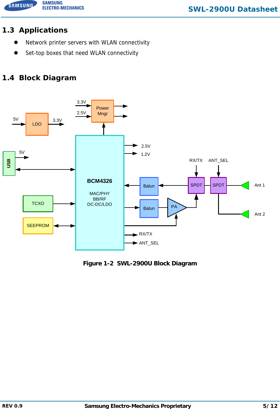
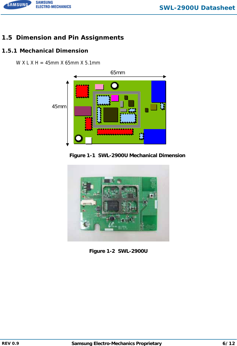
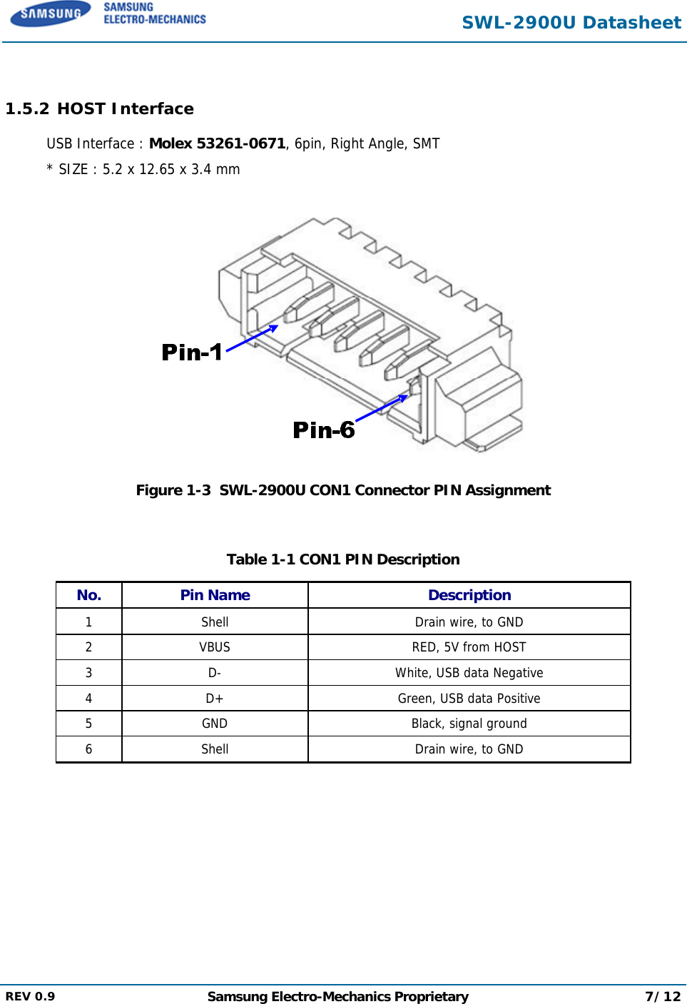
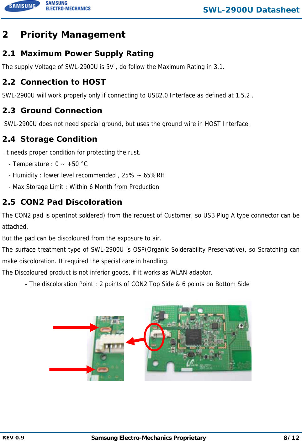
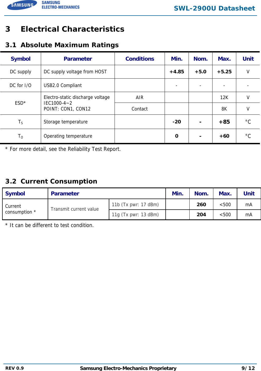
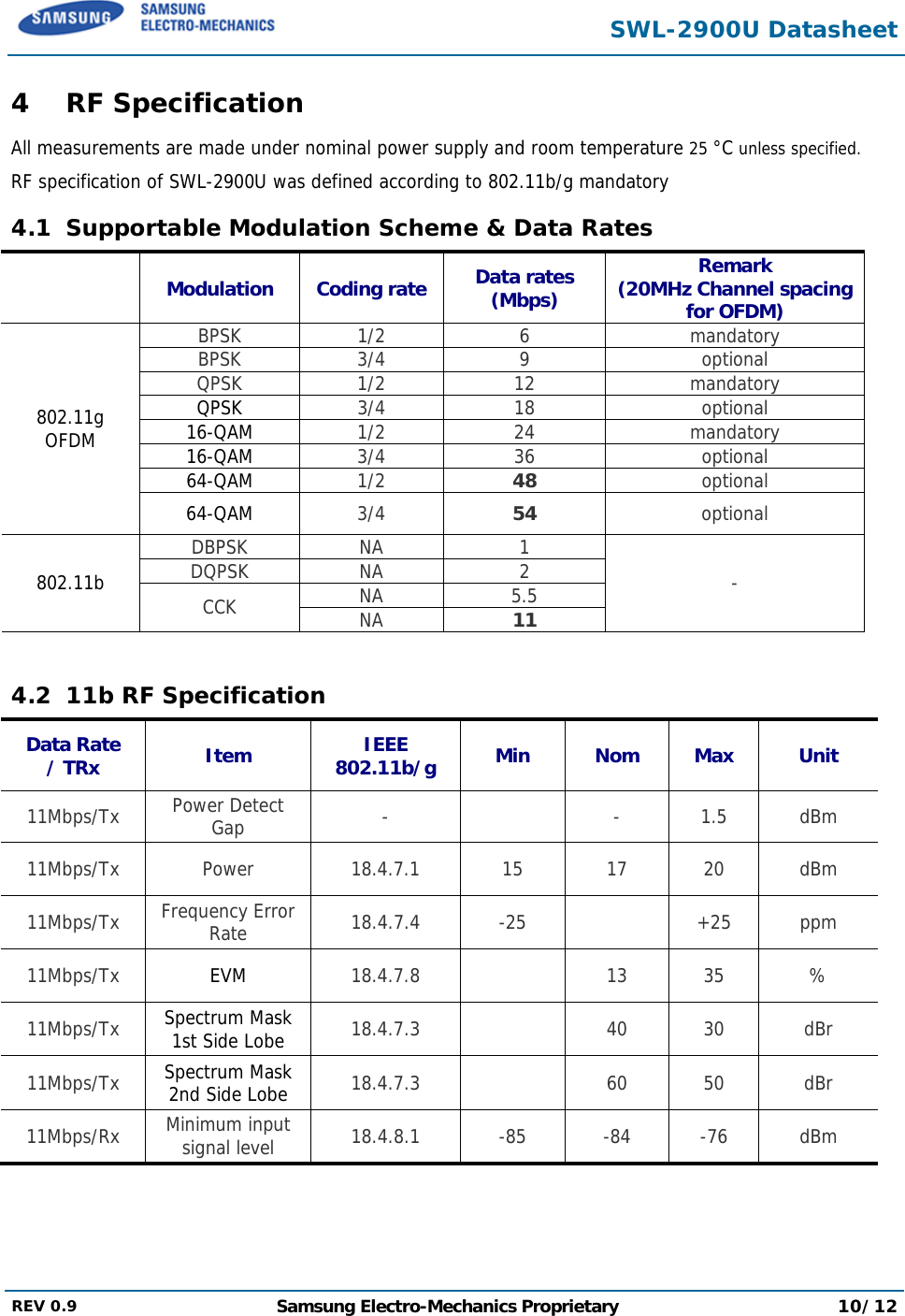
![SWL-2900U Datasheet REV 0.9 Samsung Electro-Mechanics Proprietary 11/12 4.3 11g RF Specification Data Rate / TRx Item IEEE 802.11b/g Min Nom Max Unit 48Mbps/Tx Power Detect Gap - - 1.5 dBm 48Mbps/Tx Power 19.4.7.1 10 13 15 dBm 48Mbps/Tx Frequency Error Rate 19.4.7.2 -25 0 +25 ppm 48Mbps/Tx EVM 17.3.2.2 17.3.8~17.3.9 -27 -22 dB 48Mbps/Tx Spectrum Mask 1st Side Lobe 19.5.4 40 20 dBr 48Mbps/Tx Spectrum Mask 2nd Side Lobe 19.5.4 60 28 dBr 48Mbps/Tx Spectrum Mask 3rd Side Lobe 19.5.4 60 40 dBr 48Mbps/Rx Minimum input signal level 19.5.1 -76 -74 -65 dBm 4.4 Channel & Center Frequency Channel No Center Frequency [Mbps] FCC, IC ETSI Korea 1 2412 O O 2 2417 O O 3 2422 O O 4 2427 O O 5 2432 O O 6 2437 O O 7 2442 O O 8 2447 O O 9 2452 O O 10 2457 O O 11 2462 O O 12 2467 - O 13 2472 - O](https://usermanual.wiki/Samsung-Electronics-Co/SWL-2900U/User-Guide-897400-Page-11.png)