Samsung Electronics Co WEA302I Access Point User Manual Manual
Samsung Electronics Co Ltd Access Point Manual
UserManual.wiki
>
Samsung Electronics Co
>
WEA302I User Manual
>
Manual
Contents
1.
Manual
2.
Installation Manual
Manual
Navigation menu
Upload a User Manual
Namespaces
Wiki Guide
HTML
PDF
Info
Views
User Manual
Discussion / Help
Navigation
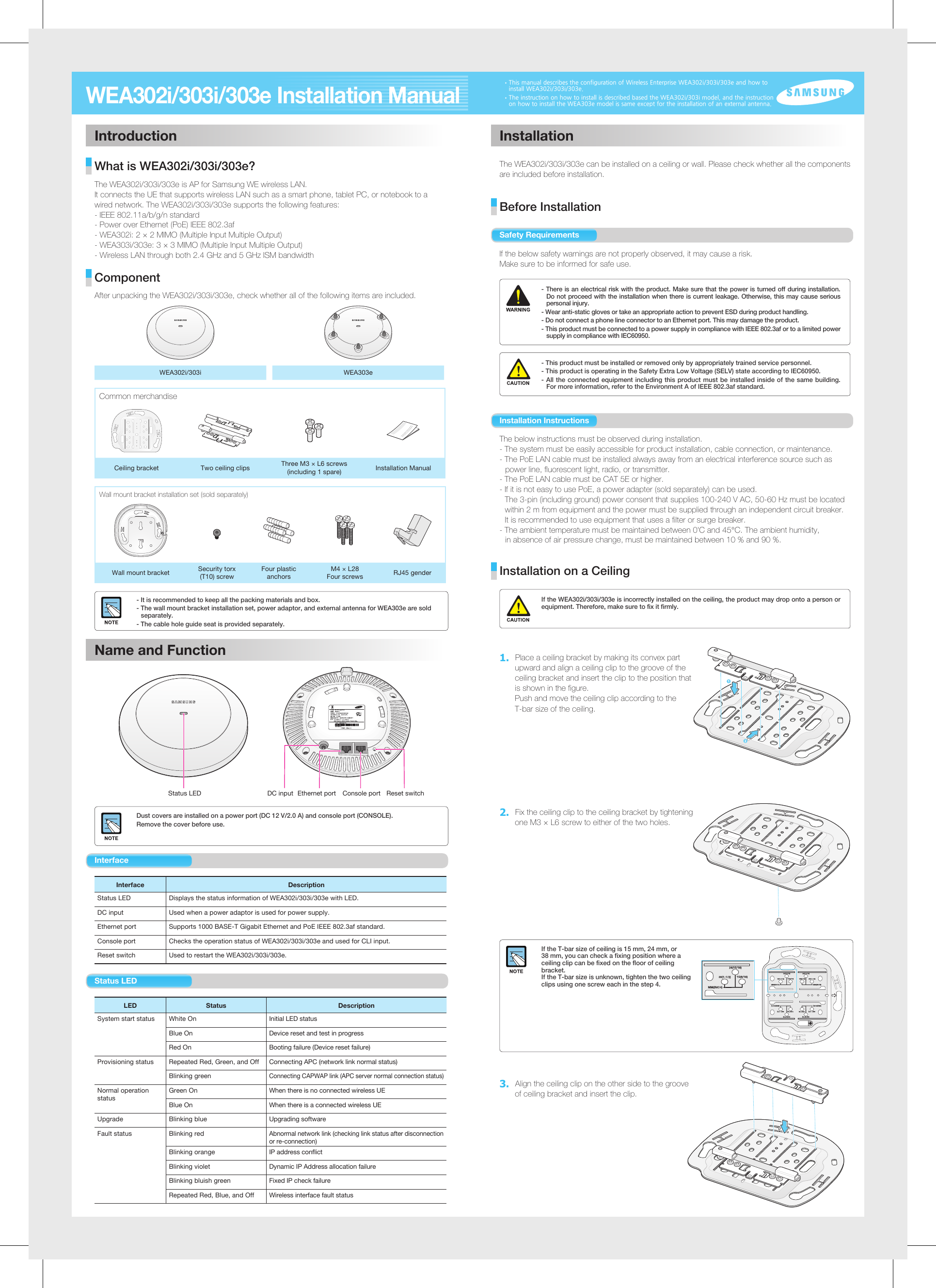
![Installation on a WallFor installation on a wall, the wall mount bracket set (sold separately) is required.1. A wall mount bracket has total 4 screw holes. Place the bracket on a wall and mark and drill 4 screw holes. When 4 screws are used When 4 screws are used When 2 screws are usedTwo screws can be used for fixing depending on a wall to install.2. Using a hammer, insert 4 plastic anchors to the holes. Align the screw holes of the wall mount bracket to the holes where the plastic anchors are inserted, and fix the wall mount bracket to the wall by tightening four M4 × L28 screws.3. First, connect a RJ45 gender to the Ethernet port on the rear side of WEA302i/303i/303e. And pass a LAN cable through the hole at the top of wall mount bracket and connect it to the RJ45 gender. If PoE is not supported, connect the power adaptor to the DC input on the back of WEA302i/303i/303e.4. After aligning the WEA302i/303i/303e to the three grooves of the wall mount bracket, fix the product by turning it clockwise. 5. To prevent theft, tighten and fix security torx (T10) screws on the sides of wall mount bracket. This equipment has been tested and found to comply with the limits for a Class B digital device, pursuant to part 15 of the FCC Rules. These limits are designed to provide reasonable protection against harmful interference in a residential installation.This equipment generates, uses and can radiate radio frequency energy and, if not installed and used in accordance with the instructions, may cause harmful interference to radio communications. However, there is no guarantee that interference will not occur in a particular installation. If this equipment does cause harmful interference to radio or television reception, which can be determined by turning the equipment off and on, the user is encouraged to try to correct the interference by one or more of the following measures: - Reorient or relocate the receiving antenna.- Increase the separation between the equipment and receiver.- Connect the equipment into an outlet on a circuit different from that to which the receiver is connected.- Consult the dealer or an experienced radio/TV technician for help.Changes or modifications not expressly approved by the party responsible for compliance could void the user’s authority to operate the equipment. Indoor use only. FCC RF Radiation Exposure Statement: This equipment complies with FCC RF radiation exposure limits set forth for an uncontrolled environment. This equipment should be installed and operated with a minimum distance of 20 cm between the radiator and your body. This transmitter must not be co-located or operating in conjunction with any other antenna or transmitter.4. After inserting the ceiling clip that is fixed with a screw (A in the figure) to the T-bar, push and move the ceiling clip (B in the figure) on the other side according to the T-bar size.[Side]AB5. After tightening two T-bar fixing screws of the ceiling clip, and fix the pushed and moved ceiling clip by tightening one M3 × L6 screw to either of two holes. As shown in the figure, the ceiling bracket is firmly fixed to the ceiling. 6. Using a cable hole guide seat separately provided, mark a hole on the ceiling tex through which a cable will be drawn out and punch a hole.Cable Hole Guide SeatCable Hole PositionCeiling Hole The cable hole guide seat is provided separately. For more information, contact the dealer.7. After separating the ceiling tex from the T-bar, draw out a LAN cable through the cable hole and connect it to the Ethernet port at the rear side of WEA302i/303i/303e. If PoE is not supported, connect the power adaptor to the DC input on the back of WEA302i/303i/303e. 8. After aligning the WEA302i/303i/303e to the three grooves of the ceiling bracket, fix the product by turning it clockwise. Arrange ceiling tex and other cables. Part No.: EC68-00172A (Ver.2.0)Class B Equipment (For Home Use Broadcasting & Communication Equipment)This equipment is home use (Class B) electromagnetic wave suitability equipment and to be used mainly at home and it can be used in all areas.Electromagnetic Wave Suitability NoticeT-bar fixing screwCeiling clip fixing screw](https://usermanual.wiki/Samsung-Electronics-Co/WEA302I.Manual/User-Guide-1997817-Page-2.png)