Samsung Electronics Co WEA453E WLAN Access Point User Manual Model Name Manual Name
Samsung Electronics Co Ltd WLAN Access Point Model Name Manual Name
Contents
- 1. Users Manual
- 2. APC Operation Manual - Professional Installation Guide 1 of 2
- 3. APC Operation Manual - Professional Installation Guide 2 of 2
- 4. APC Operational Manual_Professional Installation Guide 1 of 2
- 5. APC Operational Manual_Professional Installation Guide 2 of 2
APC Operation Manual - Professional Installation Guide 1 of 2

Ver.
2600-00FK1RGA4
6.0
WEC8500/WEC8050 (APC)
Operation Manual

COPYRIGHT
This manual is proprietary to SAMSUNG Electronics Co., Ltd. and is protected by copyright.
No information contained herein may be copied, translated, transcribed or duplicated for any commercial
purposes or disclosed to the third party in any form without the prior written consent of SAMSUNG Electronics
Co., Ltd.
TRADEMARKS
Product names mentioned in this manual may be trademarks and/or registered trademarks of their respective
companies.
This manual should be read and used as a guideline for properly installing and operating the product.
All reasonable care has been made to ensure that this document is accurate. If you have any comments on
this manual, please contact our documentation centre at the following homepage:
Homepage: http://www.samsungdocs.com
©2013~2014 SAMSUNG Electronics Co., Ltd. All rights reserved.

INTRODUCTION
© SAMSUNG Electronics Co., Ltd. page 3 of 628
INTRODUCTION
Purpose
This manual describes the overview, management, and setup of WEC8500/WEC8050 that
is a Samsung Wireless Enterprise (W-EP) Access Point Controller (APC). This manual is
written for WEC8500 version 1.4.4, WEC8050 version 1.0.0.
Document Content and Organization
This manual consists of ten Chapters, three Annexes, and a list of Abbreviations.
CHAPTER 1. Access Point Controller System Overview
This chapter describes the main functions, network configuration, external configuration
and service scenario of APC.
CHAPTER 2. Basic System Configuration
This chapter describes how to configure to use Command Line Interface (CLI) and Web UI.
CHAPTER 3. Data Network Function
This chapter describes how to set up the data network such as interface, Virtual Local Area
Network (VLAN), L3, or Quality of Service (QoS), etc. of APC.
CHAPTER 4. AP Connection Management
This chapter describes the connection management function of APC and Samsung W-EP
wireless LAN Access Point (AP).
CHAPTER 5. WLAN Management
This chapter describes how to set up the Wireless Local Area Network (WLAN) of APC.
CHAPTER 6. Wi-Fi Configuration
This chapter describes how to configure the Wireless Fidelity (Wi-Fi) of APC, QoS, and
country code.

INTRODUCTION
© SAMSUNG Electronics Co., Ltd. page 4 of 628
CHAPTER 7. WLAN Additional Service
This chapter describes how to set up WLAN additional services available in the APC.
CHAPTER 8. Security
This chapter describes how to set up security related setting such as Remote Authentication
Dial-In User Service (RADIUS) server available in the APC, unauthorized AP detection
and blocking function, guest access, WEB pass-through, Network Address Translation
(NAT), firewall function, etc.
CHAPTER 9. IP Application
This chapter describes the Internet Protocol (IP) application functions available in the APC
such as Domain Naming Service (DNS), Network Time Protocol (NTP), File Transfer
Protocol (FTP)/sFTP, or Telnet/SSH.
CHAPTER 10. System Management
This chapter describes the various system management functions available in the APC.
ANNEX A. CLI Command Structure
Command structure available in the CLI of APC.
ANNEX B. Open Source Announcement (WEC8500/WEC8050)
Open source list used in the APC and its license notice.
ANNEX C. Open Source Announcement (WEA302/WEA303/WEA312/
WEA313/WEA403/WEA412)
Open source list used in the Samsung W-EP wireless LAN AP and its license notice.
ABBREVIATION
Describes the acronyms used in this manual.
Conventions
The following types of paragraphs contain special information that must be carefully read
and thoroughly understood. Such information may or may not be enclosed in a rectangular
box, separating it from the main text, but is always preceded by an icon and/or a bold title.
NOTE
Indicates additional information as a reference.

INTRODUCTION
© SAMSUNG Electronics Co., Ltd. page 5 of 628
Console Screen Output
The lined box with ‘Courier New’ font will be used to distinguish between the
main content and console output screen text.
‘Bold Courier New’ font will indicate the value entered by the operator on the
console screen.
Revision History
VERSION
DATE OF ISSUE
REMARKS
6.0
12. 2014.
Updated the content overall in accordance with the
package version 2.4.0
5.0
05. 2014.
Updated the content overall in accordance with the
package version 2.0.0
4.0
01. 2014.
- Changed contents
1.3.1 WEC8500 Configuration and Functions
4.2.6.3 Tech Support Information
3.0
10. 2013.
- Updated the content overall in accordance with the
package version (WEC8500 version 1.4.4, WEC8050
version 1.0.0)
- Added contents for WEC8050
2.0
06. 2013.
- Updated the content overall in accordance with the
package version 1.3.0
- Added contents
3.4.6 OS-AWARE
7.4.2 DPC Configuration
7.4.3 DCS Configuration
7.4.4 CHDC Configuration
- Changed contents
7.10 Clustering
10.8.2 System Upgrade
1.0
03. 2013.
First Version

TABLE OF CONTENTS
© SAMSUNG Electronics Co., Ltd. page 6 of 628
TABLE OF CONTENTS
INTRODUCTION 3
Purpose ....................................................................................................................................... 3
Document Content and Organization .......................................................................................... 3
Conventions ................................................................................................................................ 4
Console Screen Output ............................................................................................................... 5
Revision History .......................................................................................................................... 5
CHAPTER 1. Access Point Controller System Overview 21
1.1 APC Overview .......................................................................................................................... 21
1.2 Network Configuration ............................................................................................................ 23
1.3 APC Configuration and Functions ......................................................................................... 26
1.3.1 WEC8500 Configuration and Functions ...................................................................... 26
1.3.2 WEC8050 Configuration and Functions ...................................................................... 30
1.4 APC Application Configuration and Service Scenario ......................................................... 32
1.4.1 Basic Configuration ..................................................................................................... 32
1.4.2 Configuration of Multiple APC for Redundancy ........................................................... 33
1.4.3 Clustering Configuration using Multiple APC (WEC8500) ........................................... 34
1.4.4 Configuration of Multiple Sites Consisting of Headquarter and Branches ................... 37
1.5 NAT Configuration between AP and APC .............................................................................. 39
CHAPTER 2. Basic System Configuration 40
2.1 Basic System Configuration ................................................................................................... 40
2.1.1 CLI Connection ........................................................................................................... 40
2.1.2 Managing Operator Account ........................................................................................ 41
2.1.3 APC Management Port Configuration ......................................................................... 42
2.1.4 SNMP Community Configuration................................................................................. 42
2.1.5 CLI Basic Usage ......................................................................................................... 42
2.2 Using Web UI ........................................................................................................................... 45
2.2.1 Web UI Connection ..................................................................................................... 45
2.2.2 WEC Main Window ..................................................................................................... 46
2.2.3 Managing Operator Account ........................................................................................ 47

TABLE OF CONTENTS
© SAMSUNG Electronics Co., Ltd. page 7 of 628
2.3 Initial Setup Wizard ..................................................................................................................48
2.3.1 Overview......................................................................................................................48
2.3.2 Connecting ..................................................................................................................48
2.3.3 How to Use ..................................................................................................................49
CHAPTER 3. Data Network Function 52
3.1 Port Configuration ...................................................................................................................52
3.1.1 Port management ........................................................................................................52
3.2 Interface Configuration ...........................................................................................................56
3.2.1 Interface management .................................................................................................56
3.2.2 Managing Interface Group ...........................................................................................59
3.3 VLAN Configuration.................................................................................................................61
3.3.1 VLAN ...........................................................................................................................61
3.3.2 Bridge ..........................................................................................................................63
3.3.3 Spanning Tree .............................................................................................................66
3.4 Layer 3 Protocol Configuration ..............................................................................................70
3.4.1 IP Address Configuration .............................................................................................70
3.4.2 Static Routing Configuration ........................................................................................70
3.4.3 IP Multicast Routing Configuration ..............................................................................71
3.4.4 PIM Configuration ........................................................................................................72
3.4.5 OSPF Configuration ....................................................................................................72
3.4.6 VRRP Configuration .................................................................................................. 110
3.4.7 Configuring IPWATCHD............................................................................................. 113
3.5 QoS ..................................................................................................................................... 114
3.5.1 ACL Configuration ..................................................................................................... 114
3.5.2 Class-map Configuration ........................................................................................... 118
3.5.3 Policy-map Configuration........................................................................................... 119
3.5.4 Service Policy Configuration ......................................................................................120
3.5.5 Time Profile................................................................................................................121
3.5.6 OS-AWARE ...............................................................................................................124
3.6 Multicast to Unicast ...............................................................................................................127
3.7 IP Multicast Configuration ....................................................................................................127
3.7.1 IP Multicast Routing Configuration ............................................................................127
3.7.2 PIM Configuration ......................................................................................................127
3.8 IGMP Snooping ......................................................................................................................130
3.9 Deep Packet Inspection .........................................................................................................133
3.9.1 Configuring Profile and Application Rule ...................................................................133

TABLE OF CONTENTS
© SAMSUNG Electronics Co., Ltd. page 8 of 628
3.9.2 Configuring Application Group ................................................................................... 134
3.9.3 Checking Statistics by Category ................................................................................ 134
CHAPTER 4. AP Connection Management 139
4.1 APC Management .................................................................................................................. 139
4.1.1 Managing APC List .................................................................................................... 139
4.1.2 Management Interface Configuration ........................................................................ 141
4.1.3 CAPWAP Configuration............................................................................................. 142
4.1.4 AP Registration (Auto Discovery) Configuration ........................................................ 144
4.1.5 Managing AP File Transmission ................................................................................ 145
4.1.6 APC Redundancy Configuration ............................................................................... 145
4.2 AP Management ..................................................................................................................... 151
4.2.1 AP Group Configuration ............................................................................................ 151
4.2.2 Configuring Remote AP Group .................................................................................. 167
4.2.3 AP Time Synchronization per Group ......................................................................... 173
4.2.4 AP Configuration ....................................................................................................... 175
4.2.5 Information Management .......................................................................................... 186
4.2.6 Outdoor AP Configuration ......................................................................................... 189
4.2.7 AP Package Upgrade ................................................................................................ 190
4.2.8 Remote AP Package Upgrade .................................................................................. 195
CHAPTER 5. WLAN Management 204
5.1 WLAN Configuration ............................................................................................................. 204
5.1.1 Basic WLAN Configuration ........................................................................................ 204
5.1.2 WLAN Additional Configuration ................................................................................. 207
5.1.3 WLAN-based ACL Configuration ............................................................................... 209
5.1.4 Managing Root Service ............................................................................................. 211
5.1.5 MCS Configuration Management by WLAN .............................................................. 214
5.2 Local Switching ..................................................................................................................... 217
5.3 Security and Authentication ................................................................................................. 220
5.3.1 Initialization of WLAN Security Function.................................................................... 220
5.3.2 WPA/WPA2 PSK Configuration ................................................................................. 222
5.3.3 WPA/WPA2 802.1x Configuration ............................................................................. 225
5.3.4 Static WEP Configuration .......................................................................................... 229
5.3.5 Dynamic WEP Configuration ..................................................................................... 231
5.4 DHCP Configuration .............................................................................................................. 234
5.4.1 DHCP Server ............................................................................................................ 234
5.4.2 DHCP Relay .............................................................................................................. 242

TABLE OF CONTENTS
© SAMSUNG Electronics Co., Ltd. page 9 of 628
5.4.3 DHCP Proxy ..............................................................................................................243
5.4.4 Option 82 Configuration .............................................................................................244
5.4.5 Primary/Secondary Server Configuration ..................................................................246
5.5 Radio Service Configuration .................................................................................................249
CHAPTER 6. Wi-Fi Configuration 251
6.1 802.11a/b/g/n/ac Radio Property ...........................................................................................251
6.1.1 802.11a/b/g Configuration ..........................................................................................251
6.1.2 802.11n Configuration ................................................................................................256
6.1.3 802.11ac Configuration ..............................................................................................257
6.2 Wi-Fi QoS Configuration .......................................................................................................259
6.2.1 QoS Configuration of Wireless Terminal ....................................................................259
6.2.2 QoS Configuration of AP............................................................................................261
6.2.3 Configuring QoS Profile of a Specific Terminal ..........................................................265
6.2.4 Voice Optimization Configuration ...............................................................................267
6.3 802.11h Configuration ...........................................................................................................268
6.4 Country Code .........................................................................................................................270
CHAPTER 7. WLAN Additional Services 274
7.1 Managing Wireless Terminal .................................................................................................274
7.1.1 Information Retrieval Functions .................................................................................274
7.1.2 Connection History related Configuration ..................................................................275
7.2 Handover Management .........................................................................................................276
7.2.1 Connection History Information .................................................................................276
7.2.2 AirMove Configuration ...............................................................................................276
7.2.3 Inter APC Handover Configuration ............................................................................278
7.3 Call Admission Control (CAC) Configuration ......................................................................279
7.3.1 SIP ALG Configuration ...............................................................................................279
7.3.2 Voice CAC Configuration ...........................................................................................281
7.3.3 Video CAC Configuration ...........................................................................................283
7.4 Radio Resource Management (RRM) ...................................................................................285
7.4.1 RRM Configuration ....................................................................................................285
7.4.2 DPC Configuration .....................................................................................................286
7.4.3 DCS Configuration .....................................................................................................288
7.4.4 CHDC Configuration ..................................................................................................290
7.4.5 Sleeping Cell Detection .............................................................................................294
7.4.6 Energy Saving Groups ...............................................................................................296

TABLE OF CONTENTS
© SAMSUNG Electronics Co., Ltd. page 10 of 628
7.4.7 Energy Saving Auto Classification ............................................................................. 297
7.5 Location Tracking .................................................................................................................. 300
7.6 Spectrum Analysis ................................................................................................................ 301
7.6.1 Retrieving Spectrum Analysis Data ........................................................................... 301
7.6.2 Spectrum Analysis Configuration ............................................................................... 304
7.6.3 Interference Type Configuration ................................................................................ 306
7.7 Controlling Usage per User .................................................................................................. 307
7.8 Remote Packet Capture ........................................................................................................ 309
7.9 Clustering ............................................................................................................................... 311
7.10 Limiting the Number of Connected Users ........................................................................... 315
7.10.1 Limiting Connections per Radio ................................................................................ 315
7.10.2 Connection Limitation per WLAN .............................................................................. 316
7.11 Voice Statistics and Communication Failure Detection ..................................................... 318
7.11.1 Voice Statistics Function ............................................................................................ 318
7.11.2 Detecting WLAN-based Communication Failure ....................................................... 320
7.12 Voice Signal and Media Monitoring ..................................................................................... 321
7.12.1 Checking Voice Related Wireless Information ........................................................... 321
7.12.2 Checking Voice Related Quality Information ............................................................. 326
7.13 Multicast Stream Admission Control ................................................................................... 329
7.13.1 Configuring Admission Control .................................................................................. 329
7.14 Wi-Fi Band Steering .............................................................................................................. 331
7.14.1 Activating Band Steering Function ............................................................................ 331
7.15 Wi-Fi Load Balancing ............................................................................................................ 334
7.15.1 Activating Load Balancing Function .......................................................................... 334
7.16 Station-based Adaptive Load Balancing ............................................................................. 336
7.16.1 Basic Setting of Station-based Adaptive Load Balancing .......................................... 336
7.16.2 Setting AP Group Parameter ..................................................................................... 337
7.16.3 Setting AP Parameters .............................................................................................. 339
CHAPTER 8. Security 341
8.1 RADIUS Server Configuration .............................................................................................. 341
8.1.1 External RADIUS Server ........................................................................................... 341
8.1.2 Internal RADIUS Server ............................................................................................ 347
8.2 Unauthorized AP/Terminal Detection and Blocking ........................................................... 351
8.2.1 Enabling Detection Function ..................................................................................... 351
8.2.2 Detection ................................................................................................................... 352

TABLE OF CONTENTS
© SAMSUNG Electronics Co., Ltd. page 11 of 628
8.2.3 Enabling Blocking Function .......................................................................................370
8.2.4 Blocking .....................................................................................................................370
8.3 Captive Portal .........................................................................................................................374
8.3.1 Configuring Guest Authentication ..............................................................................374
8.3.2 Configuring Guest ACL ..............................................................................................376
8.3.3 Configuring Web Authentication ................................................................................378
8.3.4 Configuring Web Authentication on MAC Authentication Failure ...............................381
8.3.5 Configuring Web Pass-through ..................................................................................385
8.3.6 Configuring One Time Redirection .............................................................................387
8.3.7 Redirection Address Format ......................................................................................389
8.4 NAT and Firewall Configuration............................................................................................390
8.4.1 Firewall Configuration ................................................................................................390
8.4.2 Access List Configuration ..........................................................................................391
8.4.3 NAT Configuration .....................................................................................................392
8.5 MAC Filter ...............................................................................................................................396
8.6 Operator Authentication through Interoperation with TACACS+ Server ..........................399
8.6.1 Configuring External TACACS+ Server .....................................................................399
8.6.2 Configuring Authentication Type of Operator Account ...............................................402
8.7 Role Based Access Control ..................................................................................................403
8.7.1 Configuring Role Profile .............................................................................................403
8.7.2 Configuring Derivation Profile ....................................................................................404
8.7.3 Configuring ACL Profile .............................................................................................407
8.7.4 Configuration Synchronization (Remote AP Group)................................................... 411
8.8 External BYOD Server ...........................................................................................................414
8.8.1 Configuring External BYOD Server ...........................................................................414
8.8.2 Captive Portal Configuration ......................................................................................416
CHAPTER 9. IP Application 419
9.1 DNS .....................................................................................................................................419
9.1.1 DNS Client Configuration...........................................................................................419
9.1.2 DNS Proxy Configuration...........................................................................................420
9.2 NTP .....................................................................................................................................422
9.3 FTP/sFTP ................................................................................................................................425
9.4 Telnet/SSH ..............................................................................................................................428
9.5 Utilities ....................................................................................................................................430

TABLE OF CONTENTS
© SAMSUNG Electronics Co., Ltd. page 12 of 628
CHAPTER 10. System Management 431
10.1 SNMP Configuration .............................................................................................................. 431
10.1.1 SNMP Community ..................................................................................................... 431
10.1.2 SNMP Trap ................................................................................................................ 432
10.2 System Management ............................................................................................................. 434
10.2.1 Retrieving System Information .................................................................................. 434
10.2.2 System Reboot .......................................................................................................... 439
10.3 System Resource Management ........................................................................................... 441
10.3.1 Retrieving System Status .......................................................................................... 441
10.3.2 Retrieving and Configuring Threshold ....................................................................... 444
10.4 Managing Alarm and Event ................................................................................................... 445
10.4.1 Retrieving Current Alarm ........................................................................................... 446
10.4.2 Retrieving History ...................................................................................................... 447
10.4.3 External Transmission Configuration ......................................................................... 449
10.4.4 Alarm Filter and Level Configuration ......................................................................... 449
10.5 Managing Traffic Performance ............................................................................................. 451
10.5.1 Managing History Information ................................................................................... 451
10.5.2 Managing Real-time Information Collection............................................................... 452
10.6 Managing License Key .......................................................................................................... 453
10.6.1 Managing SLM License (Activation) Key ................................................................... 453
10.6.2 Managing Old License Key ....................................................................................... 456
10.7 Syslog Configuration ............................................................................................................ 459
10.8 Upgrade .................................................................................................................................. 461
10.8.1 Checking Package Version ....................................................................................... 461
10.8.2 System Upgrade ....................................................................................................... 461
10.9 Configuration Management .................................................................................................. 464
10.10 Debug and Diagnosis ............................................................................................................ 466
10.10.1 Process ..................................................................................................................... 466
10.10.2 Retrieving Crash Information ..................................................................................... 468
10.11 File Management ................................................................................................................... 471
10.11.1 Retrieving Configuration of Current Directory ............................................................ 471
10.11.2 Retrieving Directory List ............................................................................................ 472
10.11.3 Revising File .............................................................................................................. 473
10.11.4 Retrieve File Content................................................................................................. 473
10.11.5 File Download and Upload ........................................................................................ 474
10.11.6 Package File ............................................................................................................. 474
10.11.7 Retrieving Storage Media .......................................................................................... 476

TABLE OF CONTENTS
© SAMSUNG Electronics Co., Ltd. page 13 of 628
10.11.8 Managing File in Web UI ...........................................................................................477
10.11.9 Statistics Function ......................................................................................................480
ANNEX A. CLI Command Structure 522
A.1 configure ................................................................................................................................522
A.2 show........................................................................................................................................552
A.3 clear ........................................................................................................................................564
A.4 debug ......................................................................................................................................566
A.5 file............................................................................................................................................569
A.6 Etc ...........................................................................................................................................569
ANNEX B. Open Source Announcement (WEC8500/WEC8050) 570
ANNEX C. Open Source Announcement (WEA302/WEA303/
WEA312/WEA313/WEA403/WEA412) 599
ABBREVIATION 624

TABLE OF CONTENTS
© SAMSUNG Electronics Co., Ltd. page 14 of 628
LIST OF FIGURES
Figure 1. System Structure for Wireless Enterprise Solution ...................................................... 22
Figure 2. W-EP Network Configuration ....................................................................................... 23
Figure 3. WEC8500 Interface-Front/Back ................................................................................... 26
Figure 4. System LED Configuration .......................................................................................... 26
Figure 5. Management Port Configuration .................................................................................. 27
Figure 6. Optic port configuration ............................................................................................... 28
Figure 7. Power module configuration ........................................................................................ 29
Figure 8. WEC8050 interface-Front/Back ................................................................................... 30
Figure 9. Status LED configuration ............................................................................................. 30
Figure 10. Ethernet Port Configurations ..................................................................................... 31
Figure 11. Basic Configuration of W-EP Wireless LAN System .................................................. 32
Figure 12. Example of W-EP Wireless LAN System Configuration for Redundancy .................. 33
Figure 13. Example of W-EP Wireless LAN System Configuration for Distributed Clustering
Service ...................................................................................................................... 35
Figure 14. Example of W-EP Wireless LAN System Configuration for Centralized Clustering
Service ...................................................................................................................... 36
Figure 15. Example of W-EP Wireless LAN System Configuration for Multiple Sites consisting of
Headquarter and Branches ....................................................................................... 37
Figure 16. AP-APC NAT Environment Configuration Diagram .................................................... 39
Figure 17. Web UI Connection Window ...................................................................................... 45
Figure 18. WEC Main Window .................................................................................................... 46
Figure 19. Operator Account Management Window ................................................................... 47
Figure 20. Operator Account Addition Window ........................................................................... 47
Figure 21. Initial Setup Wizard Welcome Screen ....................................................................... 49
Figure 22. Move to the setup step of the initial setup wizard ...................................................... 49
Figure 23. Port Management Window ........................................................................................ 54
Figure 24. Port Configuration Change Window .......................................................................... 55
Figure 25. Interfaces Window (1) ................................................................................................ 57
Figure 26. Interfaces Window (2) ................................................................................................ 57
Figure 27. Interfaces Window (3) ................................................................................................ 58
Figure 28. Interface Group Window (1) ...................................................................................... 59
Figure 29. Interface Group Window (2) ...................................................................................... 60
Figure 30. Spanning Tree Configuration Window (1) .................................................................. 68
Figure 31. Spanning Tree Configuration Window (2) .................................................................. 69
Figure 32. Spanning Tree Configuration Window (3) .................................................................. 69
Figure 33. Static Routing Configuration Window ........................................................................ 71
Figure 34. OSPF Configuration Window ..................................................................................... 73

TABLE OF CONTENTS
© SAMSUNG Electronics Co., Ltd. page 15 of 628
Figure 35. VRRP-Operation Window ........................................................................................ 112
Figure 36. VRRP-Circuit Failover Window (1) ........................................................................... 112
Figure 37. VRRP-Circuit Failover Window (2) ........................................................................... 112
Figure 38. IPWATCHD Configuration Window .......................................................................... 113
Figure 39. ACL Configuration Window ...................................................................................... 115
Figure 40. Window where a Time Profile is Applied to ACL ...................................................... 115
Figure 41. ACL Interface Configuration Window (1) .................................................................. 116
Figure 42. ACL Interface Configuration Window (2) .................................................................. 116
Figure 43. Admin ACL Configuration Window ........................................................................... 118
Figure 44. Time Profile Configuration Window (1) .....................................................................121
Figure 45. Time Profile Configuration Window (2) .....................................................................122
Figure 46. Applying to ACL .......................................................................................................123
Figure 47. IP Multicast Configuration Window ..........................................................................127
Figure 48. PIM-SM Configuration Window (1)...........................................................................128
Figure 49. PIM-SM Configuration Window (2)...........................................................................128
Figure 50. PIM-SM Configuration Window (3)...........................................................................129
Figure 51. PIM-SM Configuration Window (4)...........................................................................129
Figure 52. IGMP Snooping Config Window ...............................................................................131
Figure 53. IGMP Snooping Mroute Creation Window (1) ..........................................................131
Figure 54. IGMP Snooping Mroute Creation Window (2) ..........................................................132
Figure 55. IGMP Snooping Mroute Creation Window (3) ..........................................................132
Figure 56. IGMP Snooping Mroute Creation Window (4) ..........................................................132
Figure 57. APC List Management Window ...............................................................................140
Figure 58. Management interface configuration ........................................................................141
Figure 59. AP Registration Method Setup Window ...................................................................144
Figure 60. Redundancy Configuration Window .........................................................................148
Figure 61. AP retrieving window ................................................................................................149
Figure 62. AP redundancy Configuration Window .....................................................................150
Figure 63. AP groups configuration Window .............................................................................152
Figure 64. AP Group Addition Window ......................................................................................152
Figure 65. General Configuration Window for AP Group ..........................................................155
Figure 66. AP Add/Remove Window for AP Group ...................................................................157
Figure 67. WLAN Add/Remove Window for AP Group ..............................................................158
Figure 68. 802.11a/n Window for AP Group ..............................................................................159
Figure 69. 802.11b/g/n Window for AP Group ...........................................................................160
Figure 70. Advanced Configuration Window for AP Group........................................................166
Figure 71. Remote AP Group Add/Remove Window .................................................................168
Figure 72. Local Authentication Configuration Window for Remote AP Group ..........................169
Figure 73. Window for Configuring Tunneling Forwarding of Remote AP Group ......................171

TABLE OF CONTENTS
© SAMSUNG Electronics Co., Ltd. page 16 of 628
Figure 74. Window for Configuring Local Bridging Forwarding of Remote AP Group ............... 172
Figure 75. AP Time Synchronization Configuration Options ..................................................... 174
Figure 76. Adding Access Points .............................................................................................. 175
Figure 77. AP Profile Setting (1) ............................................................................................... 179
Figure 78. AP Profile Setting (2) ............................................................................................... 181
Figure 79. AP mode configuration ............................................................................................ 182
Figure 80. AP CLI Account Add/Remove Window .................................................................... 183
Figure 81. AP SNMP v1/v2c Community Configuration Window .............................................. 185
Figure 82. AP v3 User Configuration Window ........................................................................... 185
Figure 83. AP Ports window ...................................................................................................... 187
Figure 84. AP Ports detail information window ......................................................................... 187
Figure 85. AP Tech Support Information Receiving Window ..................................................... 188
Figure 86. Outdoor AP Create Window..................................................................................... 190
Figure 87. AP upgrade .............................................................................................................. 193
Figure 88. AP upgrade-global ................................................................................................... 193
Figure 89. AP upgrade-individual .............................................................................................. 194
Figure 90. AP upgrade-advanced ............................................................................................. 195
Figure 91. Remote AP Group Upgrade Activation_1 ................................................................ 196
Figure 92. Remote AP Group Upgrade Activation_2 ................................................................ 197
Figure 93. Checking Master AP Configuration .......................................................................... 198
Figure 94. Checking Master AP Configuration .......................................................................... 198
Figure 95. AP Package Configuration ....................................................................................... 200
Figure 96. Starting AP Upgrade ................................................................................................ 201
Figure 97. Restarting and Upgrading AP .................................................................................. 203
Figure 98. WLAN basic configuration (1) .................................................................................. 206
Figure 99. WLAN basic configuration (2) .................................................................................. 206
Figure 100. WLAN-based ACL configuration ............................................................................ 210
Figure 101. Root service management (1) ............................................................................... 213
Figure 102. Root service management (2) ............................................................................... 213
Figure 103. MCS by WLAN: 802.11a/n/ac Configuration Management window ....................... 216
Figure 104. MCS by WLAN: 802.11b/g/n Configuration Management window ......................... 216
Figure 105. Local Switching Configuration Window of WLAN .................................................. 218
Figure 106. Split ACL Configuration Window of WLAN Allocated to AP .................................... 219
Figure 107. VLAN/ACL/Pre-Auth.ACL Configuration Window of WLAN Allocated to AP .......... 219
Figure 108. Initialization of WLAN security function .................................................................. 221
Figure 109. WPA/WPA2 PSK configuration .............................................................................. 224
Figure 110. WPA/WPA2 802.1x Configuration (1) ..................................................................... 227
Figure 111. WPA/WPA2 802.1x Configuration (2) ..................................................................... 228
Figure 112. Static WEP configuration ....................................................................................... 230

TABLE OF CONTENTS
© SAMSUNG Electronics Co., Ltd. page 17 of 628
Figure 113. Dynamic WEP Configuration Window ....................................................................233
Figure 114. DHCP server configuration .....................................................................................234
Figure 115. DHCP Pool (1) .......................................................................................................240
Figure 116. DHCP Pool (2) .......................................................................................................240
Figure 117. DHCP Relay ...........................................................................................................242
Figure 118. DHCP Proxy ...........................................................................................................243
Figure 119. Option 82 configuration (1) .....................................................................................245
Figure 120. Option 82 configuration (2) ....................................................................................245
Figure 121. Primary/Secondary server configuration (1) ...........................................................247
Figure 122. Primary/Secondary server configuration (2) ...........................................................247
Figure 123. Primary/Secondary server configuration (3) ...........................................................248
Figure 124. Radio service configuration ....................................................................................250
Figure 125. 802.11a/b/g/n radio (1) ...........................................................................................254
Figure 126. 802.11a/b/g/n radio (2) ...........................................................................................255
Figure 127. QoS configuration of a wireless terminal (1) ..........................................................260
Figure 128. QoS configuration of a wireless terminal (2) ..........................................................260
Figure 129. QoS configuration of AP (wireless section) ............................................................264
Figure 130. Configuring QoS profile of a specific terminal ........................................................266
Figure 131. Configuring voice optimization ...............................................................................267
Figure 132. Configuring 802.11h ...............................................................................................269
Figure 133. Country code window (1) .......................................................................................272
Figure 134. Country code window (2) .......................................................................................273
Figure 135. Information viewing window ...................................................................................275
Figure 136. Handover window ..................................................................................................278
Figure 137. SIP ALG configuration window ...............................................................................280
Figure 138. Admission control configuration of 802.11a/n .........................................................282
Figure 139. 802.11a/n Admission Control Configuration Window .............................................284
Figure 140. RRM configuration window ....................................................................................286
Figure 141. DPC settings ..........................................................................................................287
Figure 142. DCS settings ..........................................................................................................290
Figure 143. CHDC settings .......................................................................................................293
Figure 144. Spectrum Analysis Data .........................................................................................304
Figure 145. Controlling Usage per User ....................................................................................308
Figure 146. Clustering window ..................................................................................................314
Figure 147. Clustering addition window ....................................................................................314
Figure 148. Configuring connection limitation per radio ............................................................316
Figure 149. Configuring connection limitation per WLAN ..........................................................317
Figure 150. Voice statistics .......................................................................................................319
Figure 151. Detecting WLAN-based communication failure ......................................................320

TABLE OF CONTENTS
© SAMSUNG Electronics Co., Ltd. page 18 of 628
Figure 152. VoIP Stations Retrieval Screen .............................................................................. 324
Figure 153. Active Call Retrieval Screen .................................................................................. 325
Figure 154. Complete Calls Retrieval Screen ........................................................................... 325
Figure 155. 802.11a/n Admission Control Configuration Window ............................................. 330
Figure 156. Band Steering Function On/Off and Band Setting ................................................. 333
Figure 157. Configuring Load Balancing Function .................................................................... 335
Figure 158. RADIUS server configuration ................................................................................ 343
Figure 159. RADIUS Server MAC Authentication Configuration Window ................................. 346
Figure 160. Wireless Intrusion General Configuration Window ................................................ 351
Figure 161. Managed Rule Configuration Window ................................................................... 353
Figure 162. Managed Addition Window .................................................................................... 353
Figure 163. Unmanaged Rule Configuration Window ............................................................... 355
Figure 164. Unmanaged Rule Addition Window ....................................................................... 355
Figure 165. List Window to Manually Change Classification .................................................... 357
Figure 166. Classification Change Window in AP Detail Screen .............................................. 357
Figure 167. List Window to Manually Remove.......................................................................... 358
Figure 168. Manual Remove Change Window in AP Detail Screen ......................................... 359
Figure 169. Configuration Window for Unauthorized AP Detection Option ............................... 360
Figure 170. Configuration Window for Unauthorized Station Detection Option......................... 362
Figure 171. Configuration Window for Channel Validation........................................................ 363
Figure 172. AP blacklist Configuration Window ........................................................................ 365
Figure 173. Managed AP Window ............................................................................................ 365
Figure 174. Station blacklist Search/Configuration Window ..................................................... 366
Figure 175. Managed Station Search Window .......................................................................... 366
Figure 176. Managed SSID Window ........................................................................................ 367
Figure 177. Managed/Neighbor AP Search/Configuration Window .......................................... 368
Figure 178. Managed/Neighbor AP List Addition Window......................................................... 368
Figure 179. Station Allowed Limit Configuration Window .......................................................... 369
Figure 180. Wireless Intrusion Containment General Configuration Window ........................... 370
Figure 181. List Window for Blocking AP .................................................................................. 371
Figure 182. List Window for Blocking Station ............................................................................ 372
Figure 183. Automatic Blocking Configuration Window ............................................................ 373
Figure 184. Guest User Configuration Window ........................................................................ 375
Figure 185. Guest User List Window ........................................................................................ 376
Figure 186. Guest Auth Configuration Window ......................................................................... 376
Figure 187. Access List Addition Window ................................................................................. 377
Figure 188. Access List Entry Addition Window ........................................................................ 377
Figure 189. WLAN Guest Configuration Window ...................................................................... 380
Figure 190. WLAN Web Policy Configuration Window ............................................................. 380

TABLE OF CONTENTS
© SAMSUNG Electronics Co., Ltd. page 19 of 628
Figure 191. Web Auth Configuration Window ...........................................................................380
Figure 192. WLAN Guest Configuration Window ......................................................................383
Figure 193. WLAN Layer 2 Security Configuration Window ......................................................383
Figure 194. WLAN Web Policy Configuration Window ..............................................................384
Figure 195. Web Auth Configuration Window ...........................................................................384
Figure 196. WLAN Guest Configuration Window ......................................................................386
Figure 197. Web Pass-through Configuration Window .............................................................386
Figure 198. WLAN Guest Configuration Window ......................................................................388
Figure 199. One Time Redirection Configuration Window ........................................................388
Figure 200. Firewall configuration (1) ........................................................................................390
Figure 201. Firewall configuration (2) ........................................................................................391
Figure 202. Access-list configuration ........................................................................................392
Figure 203. NAT configuration (1) .............................................................................................394
Figure 204. NAT configuration (2) .............................................................................................395
Figure 205. MAC configuration .................................................................................................397
Figure 206. MAC entry configuration window(1) .......................................................................397
Figure 207. MAC entry configuration(2) ....................................................................................398
Figure 208. MAC entry configuration(3) ....................................................................................398
Figure 209. TTACACS+ Server Configuration Window .............................................................401
Figure 210. Operator Account Authentication Type Configuration Window ...............................402
Figure 211. Role Profile Configuration ......................................................................................404
Figure 212. Role Profile Add Configuration ...............................................................................404
Figure 213. Derivation Profile Configuration .............................................................................405
Figure 214. Derivation Profile Add Configuration ......................................................................405
Figure 215. Derivation Profile Configuration .............................................................................406
Figure 216. Derivation Profile Add Configuration ......................................................................406
Figure 217. Wlan Derivation Profile Configuration ....................................................................407
Figure 218. Acl Profile Configuration .........................................................................................408
Figure 219. Acl Profile Add Configuration .................................................................................409
Figure 220. Acl Profile Edit Configuration .................................................................................409
Figure 221. Remote Ap Group-Alc Profile Configuration ...........................................................410
Figure 222. ACL Configuration Synchronization - All.................................................................412
Figure 223. ACL Configuration Synchronization - Remote Group .............................................412
Figure 224. ACL Configuration Synchronization - Remote AP ..................................................413
Figure 225. External BYOD Server Configuration Window .......................................................415
Figure 226. DNS client ..............................................................................................................420
Figure 227. DNS proxy .............................................................................................................421
Figure 228. NTP client configuration .........................................................................................424
Figure 229. FTP/SFTP server configuration ..............................................................................427

TABLE OF CONTENTS
© SAMSUNG Electronics Co., Ltd. page 20 of 628
Figure 230. Telnet/SSH server configuration ............................................................................ 429
Figure 231. Adding SNMP community ...................................................................................... 432
Figure 232. SNMP trap configuration ....................................................................................... 433
Figure 233. System information ................................................................................................ 437
Figure 234. Reboot (APC) ........................................................................................................ 439
Figure 235. Reboot (AP) ........................................................................................................... 440
Figure 236. Configuring SNMP alarm threshold ....................................................................... 444
Figure 237. Current alarm ........................................................................................................ 446
Figure 238. History ................................................................................................................... 448
Figure 239. Configuring alarm filter and level ........................................................................... 450
Figure 240. SLM License Search and Configuration Window .................................................. 455
Figure 241. Old License Installation Check Window ................................................................. 458
Figure 242. Syslog window ....................................................................................................... 460
Figure 243. Package upgrade (APC) ........................................................................................ 463
Figure 244. DB Backup/Restore ............................................................................................... 465
Figure 245. File management window ...................................................................................... 477

CHAPTER 1. Access Point Controller System Overview
© SAMSUNG Electronics Co., Ltd. page 21 of 628
CHAPTER 1. Access Point Controller
System Overview
1.1 APC Overview
The Samsung Access Pointer Controller (APC) comprehensively manages the user
information and traffics while managing an Access Point (AP), i.e. a device that provides
wireless connection service for a user terminal in a Wi-Fi environment. There are two types
depending on the AP capacity; WEC8500 and WEC8050. It comprehensively manages all
the APs and provides services in a wireless LAN environment. Because AP and APC are
connected in tunneling, all the user traffics are exchanged and processed.
The APC is typically installed at a position where it can be connected to a backbone switch,
core switch or router in a network of enterprise environment and it controls a wireless LAN
AP and provides the functions for Wireless LAN (WLAN) services such as handover and
QoS, security/authentication, etc. The Samsung WEC8500 provides its services up to 500
APs. It can provide its services up to 10,000 connected user devices. Meanwhile, the
WEC8050 can accommodate maximum 75 APs and provides the service to maximum 1500
user devices.
The APC provides a WLAN network environment through AP management and also
provides various communication services required by enterprise customers in a wireless
environment by interoperating with other enterprise solutions. It provides Wireless
Enterprise (W-EP) solution in an enterprise environment by making the collaboration
applications such as telephone, message, or communicator, etc., that has been used in a
legacy wire environment, be able to be used in a wireless terminal such as smart phone,
tablet PC, or notebook.
CHAPTER 1. Access Point Controller System Overview
© SAMSUNG Electronics Co., Ltd. page 22 of 628
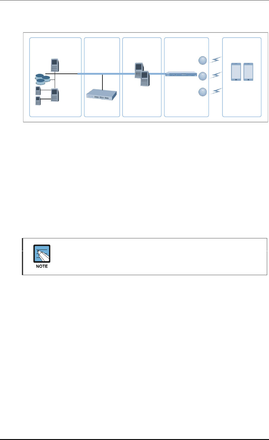
Figure 1. System Structure for Wireless Enterprise Solution
The Samsung W-EP solution, as shown in figure, comprehensively includes various
enterprise applications which are provided by wire/wireless infrastructure products and
wireless terminals. The WLAN network, a wireless infrastructure solution that provides
mobility in an enterprise environment, consists of W-EP wireless LAN Access Point (AP),
W-EP AP Controller (APC), and Wireless Enterprise WLAN Manager (WEM).
The Samsung APC and W-EP wireless LAN AP are core devices that provide various
services such as user authentication, wireless management, voice and data service, etc. in
the 802.11-based Wi-Fi environment. The WEM provides convenient configuration
environment, various statistics, and event information to an operator.
Term
In this manual, the WEC8500/WEC8050 and APC commonly represent Samsung
AP Controller. In addition, the AP means Samsung W-EP wireless LAN AP.
Enterprise
Mobile Server
IP-PBX
Groupware
(Mail, PIMS)
FFA/ERP
SFA/CRM etc.
Call Manager
Legacy System
Push Mail/Payment
Mobile device
management, etc.
WLAN Network
APC
(WEC8500)
Wireless
Terminal
Mail, UC Service
based on Android
W-EP AP
CHAPTER 1. Access Point Controller System Overview
© SAMSUNG Electronics Co., Ltd. page 23 of 628
1.2 Network Configuration
The network configuration of Samsung W-EP solution that includes APC is shown below.
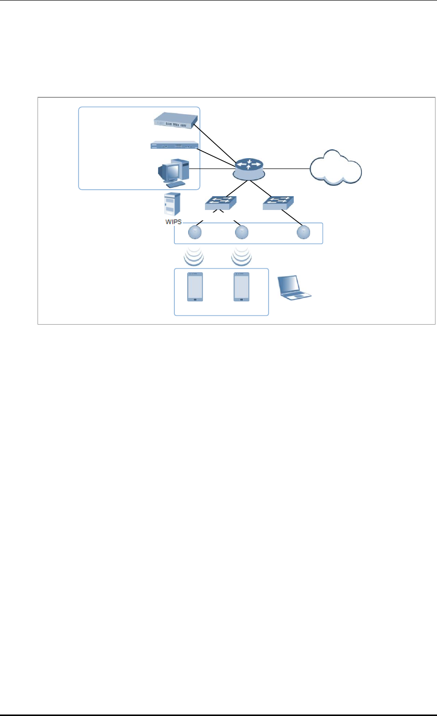
Figure 2. W-EP Network Configuration
IP-PBX
As an enterprise call manager, it is a switch required to provide the Fixed Mobile
Convergence (FMC) function to a wireless terminal (optional).
APC (WEC8500/WEC8050)
The APC manages all the W-EP wireless LAN APs installed in an enterprise
communication environment and it also manages user information and traffics.
Because the W-EP wireless LAN network configuration uses a centralized structure where
all the wireless user traffics are in tunneling through the APC, the APC is one of the most
important elements related to traffic management and throughput in the W-EP environment.
An APC is typically installed at a position where it can be connected to a backbone switch,
core switch or router in a network. It controls the W-EP wireless LAN AP and provides
handover, QoS, and security/authentication functions.
WEM
In the W-EP wireless LAN environment, various services are provided through a complex
network configuration. As many users are involved, its management is complex and
difficult. A normal network administrator can hardly handle any problematic issue as well
as a normal management task. The WEM is a Network Management System (NMS) that
efficiently manages this kind of W-EP wireless LAN network and service environment.
It manages a WLAN network, retrieves and configures the status of APC or W-EP wireless
LAN AP.
W-EP AP
IP-PBX
WEC8050/WEC8500
WEM
Router
Internet
…
…
Ethernet Switch
FMC client

CHAPTER 1. Access Point Controller System Overview
© SAMSUNG Electronics Co., Ltd. page 24 of 628
W-EP AP (W-EP Wireless LAN AP)
The W-EP wireless LAN AP is a device that provides wireless connection service to a user
terminal. It should be installed by considering the service area or region that will be
provided in an enterprise environment. Typically, the number of W-EP wireless LAN APs
is determined by considering the size of installation area and the number of users to secure
service coverage.
Ethernet Switch
Typically, because an AP is installed in a user area, use a Power over Ethernet (PoE) switch
that does not use a power line for the beauties of environment, etc. Install the W-EP
wireless LAN APs by considering current consumption and the power capacity PoE switch.
In addition, because power drop may occur if the distance between the switch and W-EP
wireless LAN AP, the relationship between distance and power must be considered.
Typically, the distance between these two must be 100 m or less in order to avoid power
drop.
Wireless terminal/FMC Client
Terminal that provides the 802.11a/b/g/n interface such as smart phone, tablet PC, or
notebook computer, etc. In an Android smart phone, an enterprise Voice over IP (VoIP)
application equipped with the Samsung voice engine is called a FMC client (The FMC
client is an option).
Wireless additional service
In the W-EP environment, various application services are required as well as basic
wireless connection services.
The Wireless Intrusion Prevention System (WIPS) provides a security service that is one of
the most important elements in an enterprise environment. The WIPS can seamlessly
receive wireless connection service through the security services such as unauthorized
terminal, unauthorized AP, or ad hoc connection blocking, etc.
Location service that manages the location of a terminal in a wireless environment is also
an application service required in an enterprise environment. With this, it is possible to
manage the location of an effective user or an unauthorized user.
IP application service
The IP application servers required in an existing wire network including Dynamic Host
Configuration Protocol (DHCP) server, DNS server, web server, or RADIUS authentication
server are also used in the W-EP environment. Especially, the DHCP server and RADIUS
authentication server play a critical role in the wireless environment.

CHAPTER 1. Access Point Controller System Overview
© SAMSUNG Electronics Co., Ltd. page 25 of 628
WIPS Solution
It monitors the properness of the implementation of the wireless network infrastructure by
detecting penetration via unauthorized wireless equipment installed in the internal network,
the detoured gateway segment of the internal officers and employees who illegally connect
to the commercial WLAN service, etc. and provides the wireless network invasion
detection which implements the safe and effective wireless network environment by
detecting security vulnerabilities.
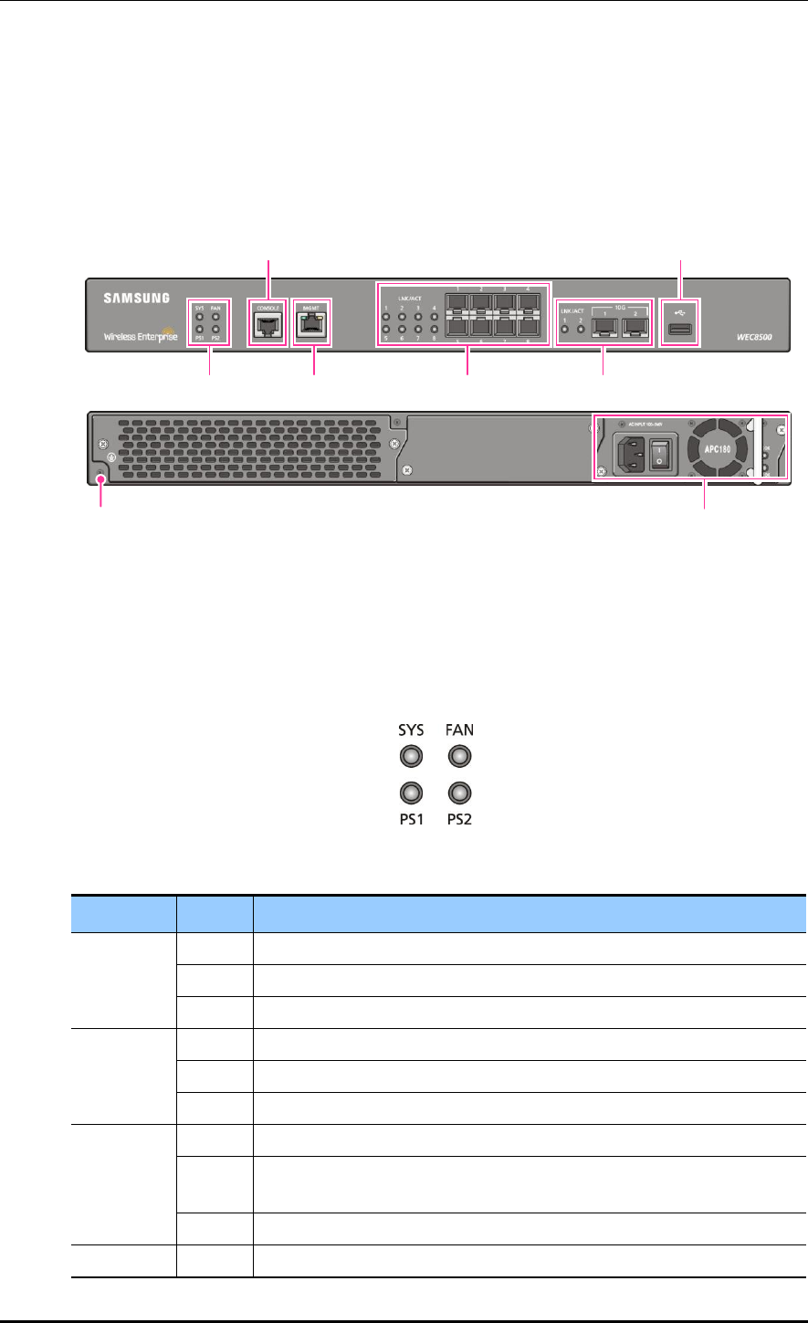
CHAPTER 1. Access Point Controller System Overview
© SAMSUNG Electronics Co., Ltd. page 26 of 628
1.3 APC Configuration and Functions
1.3.1 WEC8500 Configuration and Functions
The Configuration and the purpose of each item of WEC8500 are as follows:
Figure 3. WEC8500 Interface-Front/Back
System LED
System LED indicates the various statuses of system. Each LED displays the following
information.
Figure 4. System LED Configuration
LED
Status
Description
SYS
Green
The system is operating normally
Orange
The system is now booting
Red
Preparing the system for booting
FAN (fan
module)
Green
The installed FAN module is operating normally
Orange
The system is now booting
Red
Fan module fault has occurred
PS1 (power
module 1)
Green
Normal operation of installed power module 1
Red
Power is turned off or a fault occurred while the power module 1 is
installed.
Off
Power module 1 is not installed.
PS2 (power
Green
Normal operation of installed power module 2
Power Module
Ground hole
System LED
Console port
Management port
1G Optic port
10G Optic port
USB port
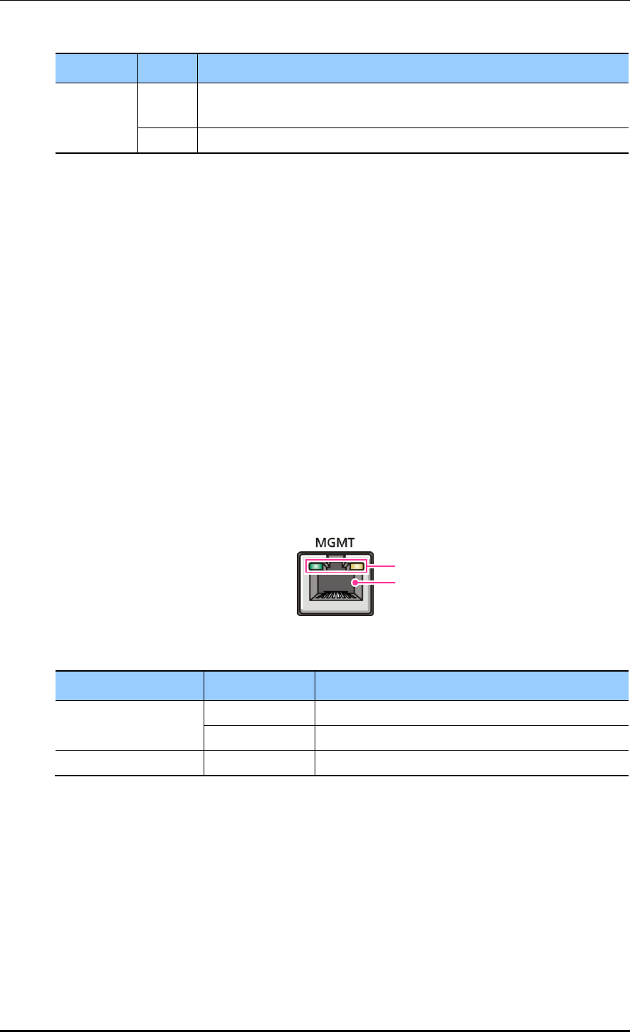
CHAPTER 1. Access Point Controller System Overview
© SAMSUNG Electronics Co., Ltd. page 27 of 628
LED
Status
Description
module 2)
Red
Power is turned off or a fault occurred while the power module 2 is
installed.
Off
Power module 2 is not installed.
Console port (RS232C)
A console port is used to check the operational status of WEC8500 or for input through the
CLI. Its basic requirements are as follows:
Baud rate: 115200 bps
Character size: 8 characters
Parity: None
Stop bit: 1, Data bit: 8
Flow control: None
Management port (1 GE UTP)
The WEC8500 provides a 10/100/1000BASE-T port (RJ-45) for management purpose.
It is working in 10/100 Mbps half duplex/full duplex mode or in 1000 Mbps full duplex
mode. Because it supports the automatic MDI/MDI-X function, you can use a straight-
through cable for all the network connections to a PC, server, switch, or network hub.
Figure 5. Management Port Configuration
Configuration item
Status
Description
LED
Green
Turned on for link connection
Orange
Blinking for data exchange
Connector
-
Connector for UTP cable connection
When connecting a cable to the management port, make sure to check if the cable complies
with the 10 BASE-T, 100 BASE-TX, or 1000 BASE-T.
Cable type: UTP or STP cable using RJ-45 connector
10 BASE-T: Category 3 or higher
100 BASE-TX: Category 5 or higher
1000 BASE-T: Category 5 or higher (Category 5e or higher is recommended)
Isolate from wireless frequency disturbing waves
Shut down electrical surge
LED
Connector
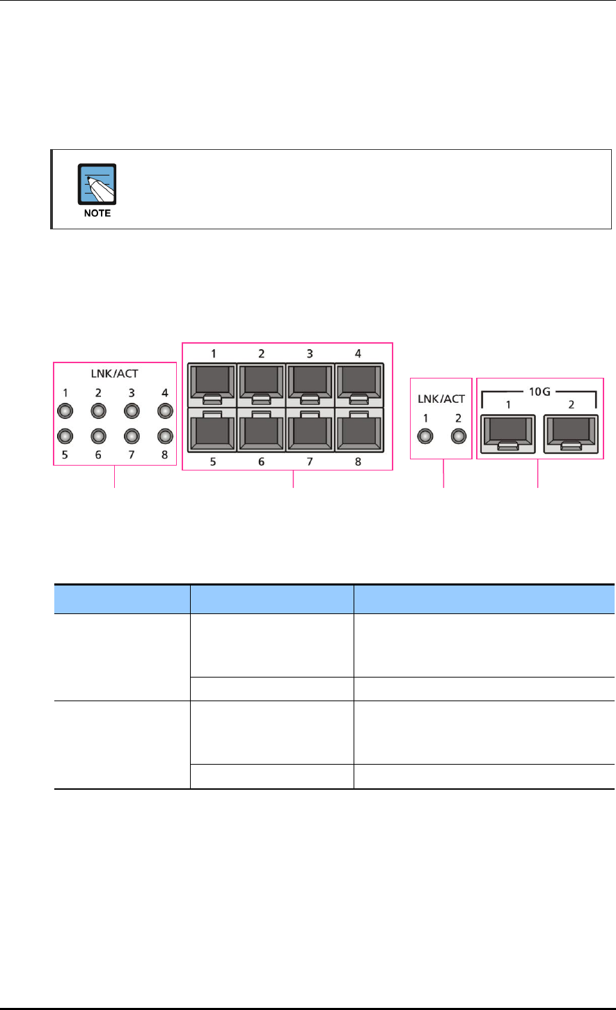
CHAPTER 1. Access Point Controller System Overview
© SAMSUNG Electronics Co., Ltd. page 28 of 628
Separate the electrical wiring of a switch or related devices and the electromagnetic
area of network data line
Cable or connector and safe connection without damaged cable sheath
The 1000 BASE-T standard does not support the forced mode.
The auto-negotiation function must be always used for 1000 BASE-T port or trunk
connection.
Optic port
It provides two 10 GbE Optic ports and eight 1 GbE Optic ports and the operational status
of each port is displayed in LED.
Figure 6. Optic port configuration
Configuration item
Port/LED
Description
10 GE ports
LINK/ACT 1, LINK/ACT 2
LINK/ACT status of each port
- Turned on for link connection
- Blinking for data exchange
10G 1, 10G 2
10 GbE Optic module connector
1 GE port
LINK/ACT 1~LINK/ACT 8
LINK/ACT status of each port
- Turned on for link connection
- Blinking for data exchange
1G 1~1G 8
1 GbE Optic module connector
USB port (Host 2.0)
The WEC8500 provides a USB host port that supports the upgrade of WEC8500 operation
software.
A typical USB memory stick is supported.
1G port
LINK/ACT LED
1G port
Connector
10G port
Connector
10G port
LINK/ACT LED

CHAPTER 1. Access Point Controller System Overview
© SAMSUNG Electronics Co., Ltd. page 29 of 628
Power module
Figure 7. Power module configuration
Configuration item
Description
Power input connector
Connector to connect the power cable to
Power switch
Switch to turn on/off power
AC LED
Turned on when there is a normal AC power input.
DC LED
Turned on when there is a normal DC power output.
Power input
connector
AC LED
Power
switch
DC LED
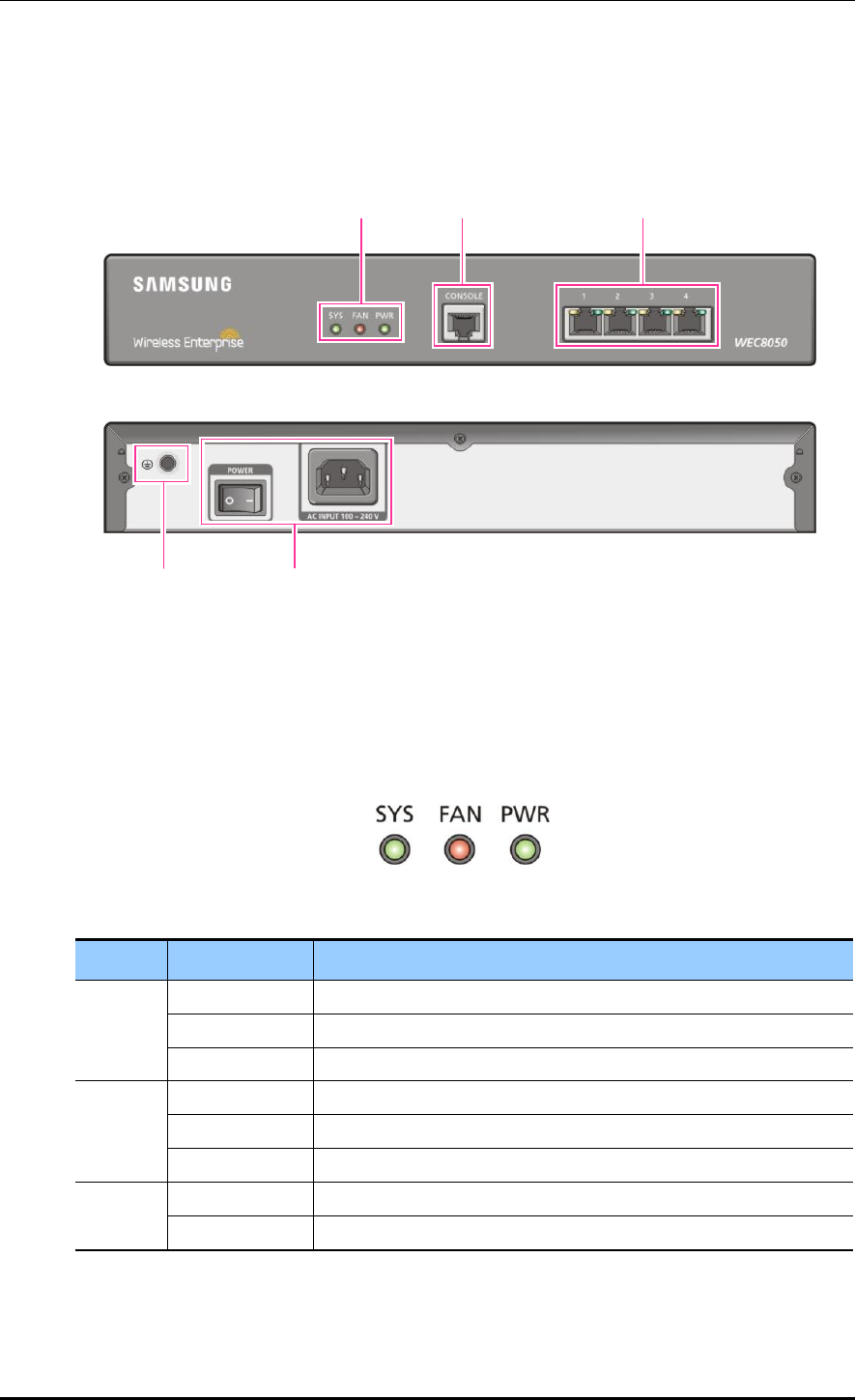
CHAPTER 1. Access Point Controller System Overview
© SAMSUNG Electronics Co., Ltd. page 30 of 628
1.3.2 WEC8050 Configuration and Functions
The configuration and the purpose of each item of WEC8050 are as follows:
Figure 8. WEC8050 interface-Front/Back
Status LED
This LED indicates the various statuses of system. Each LED displays the following
information.
Figure 9. Status LED configuration
LED
Status
Description
SYS
Green
The system is operating normally
Orange
The system is now booting
Red
Preparing the system for booting
FAN
Green
The installed FAN module is operating normally
Orange
The system is now booting
Red
Fan fault
PWR
Green
The power is supplied normally
Off
The power is turned off or not supplied
Status LED
Console Port
Ethernet Port
Ground hole
Power
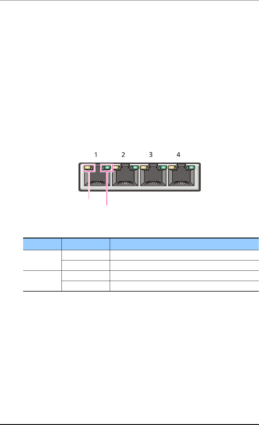
CHAPTER 1. Access Point Controller System Overview
© SAMSUNG Electronics Co., Ltd. page 31 of 628
Console port (RS232C)
A console port is provided to check the operational status of WEC8050 or for input through
the CLI.
Its basic requirements are as follows:
Default baud rate: 115200 bps
Character size: 8 Characters
Parity: None
Stop bit: 1, Data bit: 8
Flow control: None
Ethernet port
It has 4 10/100/1000 Base-T ports.
Figure 10. Ethernet Port Configurations
LED
Status
Description
ACT
Orange blinking
Blinking while data exchanging
Off
No data exchanging
LINK
Green
Link connection display
Off
No link connection
LINK LED
ACT LED
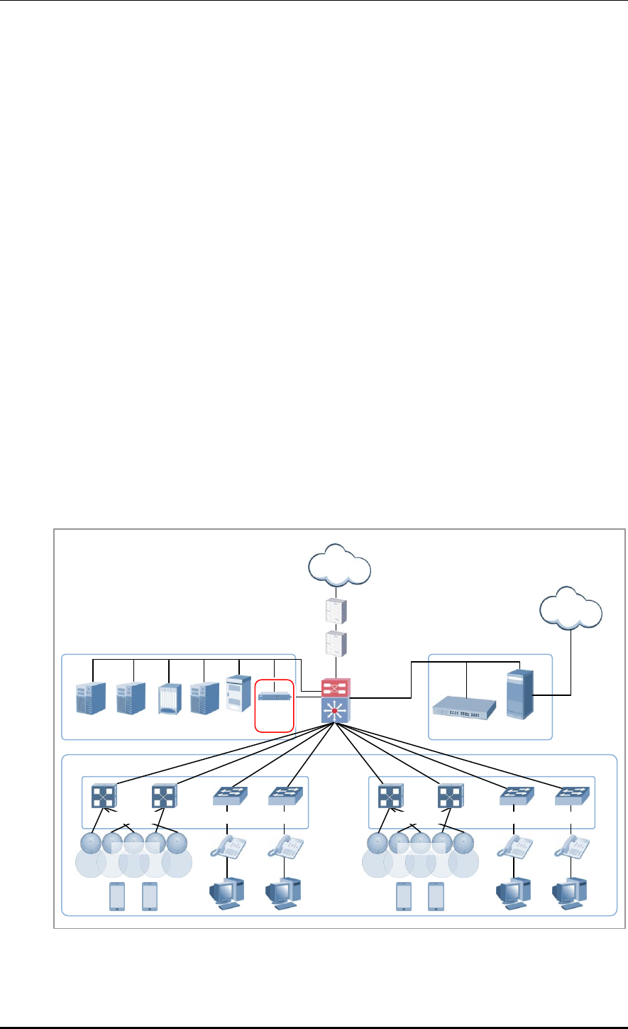
CHAPTER 1. Access Point Controller System Overview
© SAMSUNG Electronics Co., Ltd. page 32 of 628
1.4 APC Application Configuration and Service
Scenario
1.4.1 Basic Configuration
To provide wireless connection service using a wireless LAN in the W-EP environment, the
W-EP wireless LAN AP that helps a terminal connect to the network through wireless and
an APC that controls the terminal are basically required. Especially, the role of APC is
critical to guarantee QoS of various services and provide high level of security functions in
an Enterprise communication environment. As various elements are required in the W-EP
environment, it is necessary to intuitively or organically manage each element via WEM.
In addition, the IP application servers including authentication server, DHCP server, or
DNS server which is a basic network configuration element in a wire enterprise
environment are also interoperated to provide more convenient and various mobile services
to users. One outstanding example is the FMC service that provides enterprise level VoIP in
a wireless LAN. With this, the wire/wireless integrated voice service can be provided.
An example of service configuration diagram using the W-EP wireless LAN system is
shown in the below figure. The configuration diagram is based on Samsung APC
(WEC8500).
Figure 11. Basic Configuration of W-EP Wireless LAN System
PRI
Firewall
Internet
Backbone
switch
SBC
PSTN
IP-PBX
Media G/W
APC
WIPS
Loc
server
WEM
AAA
server
DHCP
W-EP AP
PoE switch
Access switch
PoE switch
Access switch
W-EP AP
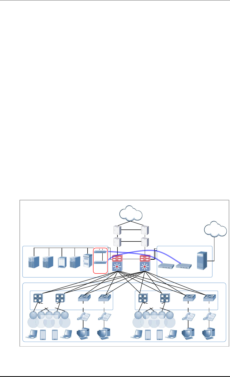
CHAPTER 1. Access Point Controller System Overview
© SAMSUNG Electronics Co., Ltd. page 33 of 628
The basic W-EP wireless LAN network configuration is a centralized structure where all
the wireless user traffics go through tunneling between APC and W-EP wireless LAN AP.
Therefore, the network information such as subnet information allocated to a wireless user
depends on the configuration of backbone network where the APC is connected.
This provides the following advantages during network configuration and setup.
Installing the APC is just adding it to a legacy data center or backbone network.
Therefore, the possibility of physical change of core network can be reduced.
In addition, separate design of wire/wireless network is easy using the APC as a
boundary.
No dramatic network change is required to install the W-EP wireless LAN AP.
An AP installed in a user area is located in various local network environments in a wide
region. Although it is unavoidable to install or expand a PoE switch, the modification of
local network where wire users are already configured can be minimized.
Because the APC relays all the user traffics, it can restrict a wireless attacker’s effects
and provide differentiated service for each user.
1.4.2 Configuration of Multiple APC for Redundancy
The APC provides the redundancy function to guarantee QoS for various services and
provide service stability in the W-EP environment.
An example of service configuration diagram for redundancy is shown in the below figure.
Figure 12. Example of W-EP Wireless LAN System Configuration for Redundancy
PRI
Firewall
Internet
Backbone
switch
SBC
PSTN
IP-PBX
Media G/W
APC
WIPS
Loc
server
WEM
AAA
server
DHCP
PoE switch
Access switch
PoE switch
Access switch
IP-PBX
W-EP AP
W-EP AP

CHAPTER 1. Access Point Controller System Overview
© SAMSUNG Electronics Co., Ltd. page 34 of 628
In this configuration, several APC s are used to minimize service disruption caused by a
disconnected APC and to enhance service sustainability. Basically, two or more APC s
must be installed in the same site for APC redundancy. The redundancy configuration
includes active-active configuration, active-standby configuration, and many-to-one
configuration. An operator can select a configuration based on the number of available
APC s and redundancy level.
1.4.3 Clustering Configuration using Multiple APC (WEC8500)
The W-EP environment has various area sizes, user density and number of users. If only a
single APC is required for service and management, the complexity of network
configuration or management is not high. However, if the capacity of a single APC is not
sufficient, multiple APC s must be installed for service. The WEC8500 is a Samsung APC
model providing the clustering environment.
To set up a wireless LAN network in an environment where multiple WEC8500s are
installed, the integrated management system and user service must be provided through
clustering configuration between the WEC8500s. This allows inter APC handover.
The WEC8500s configured in a cluster provides a service just like a single WEC8500
through periodic information exchange.
Inter APC handover
The inter APC handover is a handover between APCs. A clustering group is used
to provide this function and this clustering group means a virtual area.
Maximum 12 WEC8500s can be bound to a single group. An APC in a group
cannot be added to another group.
It provides layer 3 handover and the handover is supported when a terminal
moves to an APC which have different subnets. A serving APC is called as an
anchor APC and a target APC is called as a foreign APC. The control path and
also the tunnel for data traffic between APCs provide security using IPSec.
The inter APC handover provides this function both in the standard Wi-Fi
handover and Samsung’s unique AirMove method.
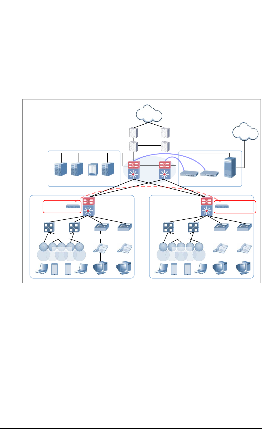
CHAPTER 1. Access Point Controller System Overview
© SAMSUNG Electronics Co., Ltd. page 35 of 628
1.4.3.1 Configuration of Distributed Clustering Service
The configuration of distributed clustering is to install each WEC8500 in a building or a
local site according to its capacity. This option can be used when there is no integrated
backbone configuration in a site or networks are separated for each building. It is suitable
for a site where several buildings are apart from each other.
An example of service configuration diagram is shown in the below figure.
Figure 13. Example of W-EP Wireless LAN System Configuration for Distributed Clustering Service
PRI
Firewall
Internet
Backbone
switch
SBC
PSTN
IP-PBX
Media G/W
Loc
server
WEM
AAA
server
DHCP
PoE switch
Access switch
PoE switch
Access switch
IP-PBX
WEC8500
(building-2)
APC Clustering
W-EP AP
W-EP AP
WEC8500
(building-1)
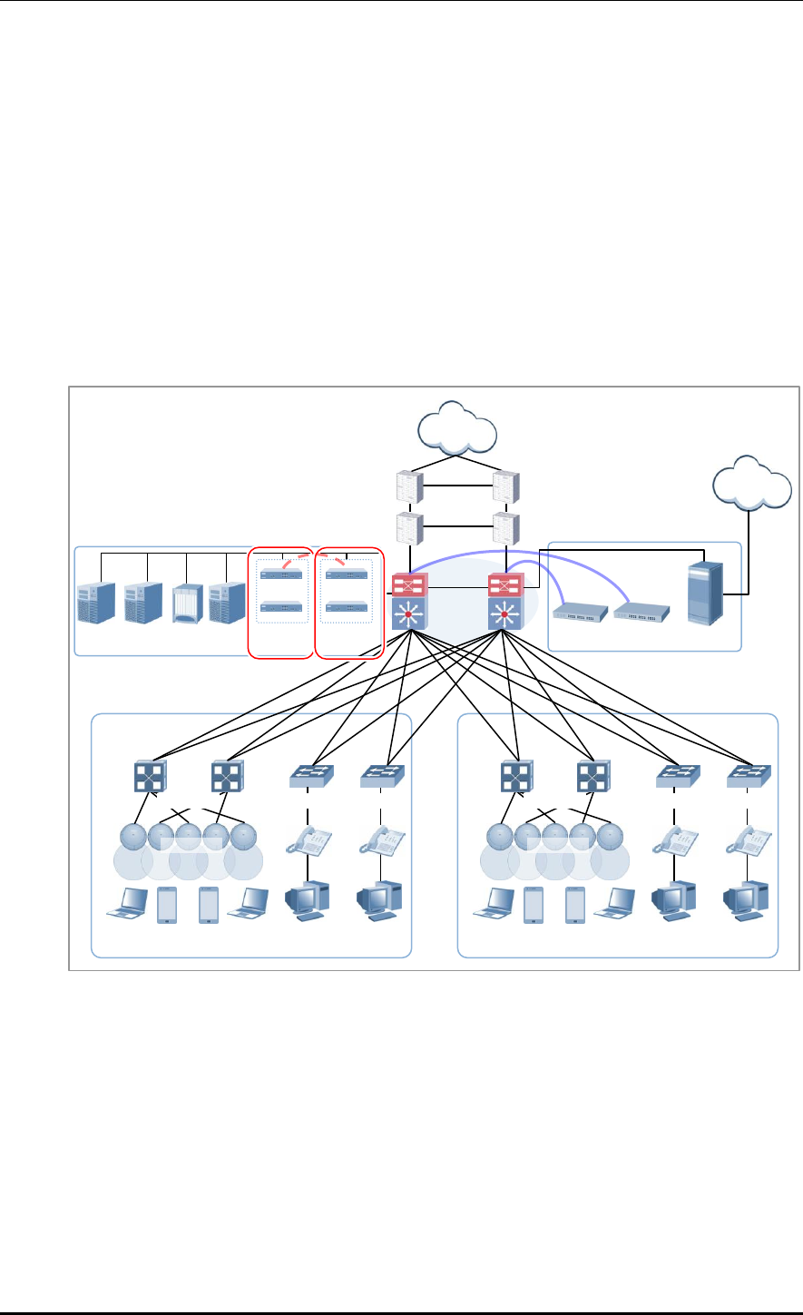
CHAPTER 1. Access Point Controller System Overview
© SAMSUNG Electronics Co., Ltd. page 36 of 628
1.4.3.2 Configuration of Centralized Clustering Service
In the centralized cluster configuration, all the WEC8500s in a site are installed in the
center. This is suitable when all the networks in a site are configured around the backbone.
This option is suitable for a site where several buildings are close to each other or a large
building where a seamless handover service is required using one or more WEC8500s.
Better performance can be obtained if there is a single backbone network and it is
preferable in terms of installation or maintenance because its service configuration is
simple.
An example of service configuration diagram is shown in the below figure.
Figure 14. Example of W-EP Wireless LAN System Configuration for Centralized Clustering Service
WEM
AAA
server
DHCP
PRI
Firewall
Internet
Backbone
switch
SBC
PSTN
IP-PBX
Media G/W
PoE switch
Access switch
PoE switch
Access switch
IP-PBX
APC Clustering
Loc
server
Building-1
Building-2
W-EP AP
W-EP AP
WEC8500
(building-1)
WEC8500
(building-2)
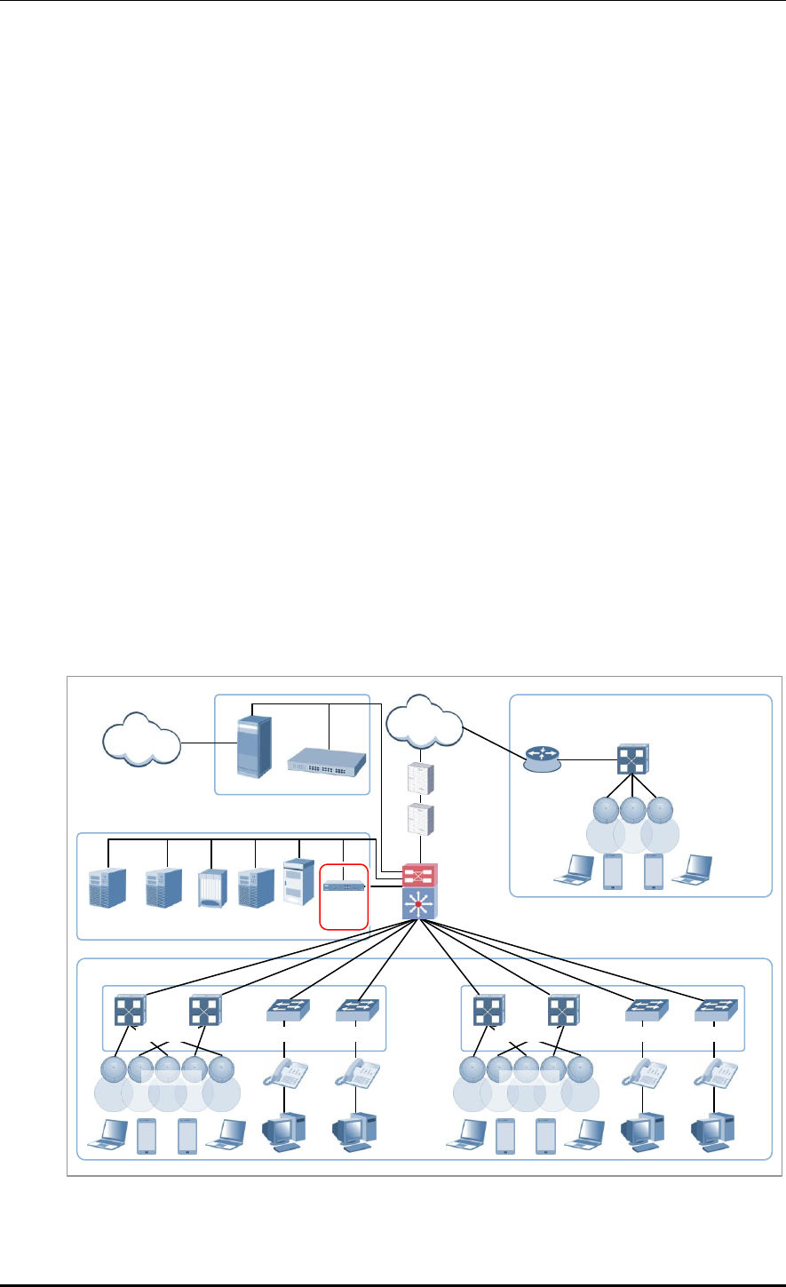
CHAPTER 1. Access Point Controller System Overview
© SAMSUNG Electronics Co., Ltd. page 37 of 628
1.4.4 Configuration of Multiple Sites Consisting of Headquarter
and Branches
The W-EP wireless LAN network environment usually consists of one headquarter and
several branches.
In this case, there are two types of network configuration.
Hierarchical type: A APC is installed in a branch as well as headquarter.
Branch AP type: A APC is installed only in a headquarter and only a W-EP wireless
LAN AP is installed in a branch.
In the hierarchical type, it is advantageous that each branch can use each different service
policy. However, the management in headquarter is complex and many low-capacity APCs
must be installed, so the branch AP type is commonly used.
The branch AP type has the same structure as a basic W-EP wireless LAN configuration.
A single difference is that a W-EP wireless LAN AP installed in a branch is located at a
remote place. The APC in headquarter provides a wireless LAN service in the headquarter
building and also provides a wireless LAN service to a remote W-EP wireless LAN AP
installed in a branch. As the APC in headquarter manages all the W-EP wireless LAN APs
using the same policy, it is easy to use and cost-effective.
An example of service configuration diagram for the branch AP type is shown in the below
figure.
Figure 15. Example of W-EP Wireless LAN System Configuration for Multiple Sites consisting of
Headquarter and Branches
PRI
Firewall
Internet
Backbone
switch
SBC
PSTN
IP-PBX
Media G/W
APC
WIPS
Loc
Server
WEM
AAA
server
DHCP
Router
Branch
PoE switch
W-EP AP
HQ
PoE switch
Access switch
PoE switch
Access switch
W-EP AP
W-EP AP

CHAPTER 1. Access Point Controller System Overview
© SAMSUNG Electronics Co., Ltd. page 38 of 628
If user traffics are concentrated on a single centralized APC when there are many branches
or they are far from headquarter, performance may be deteriorated due to the time delay of
packet transmission, etc. Therefore, use different operation schemes according to the
location of W-EP wireless LAN AP in the configuration of headquarter and branches.
In other words, the local W-EP wireless LAN AP in a headquarter does traffic tunneling to
an APC and the branch AP installed in a branch switches a user traffic directly to a
destination address without tunneling to the APC. Even at this time, the APC in
headquarter manages all the W-EP wireless LAN APs and users.
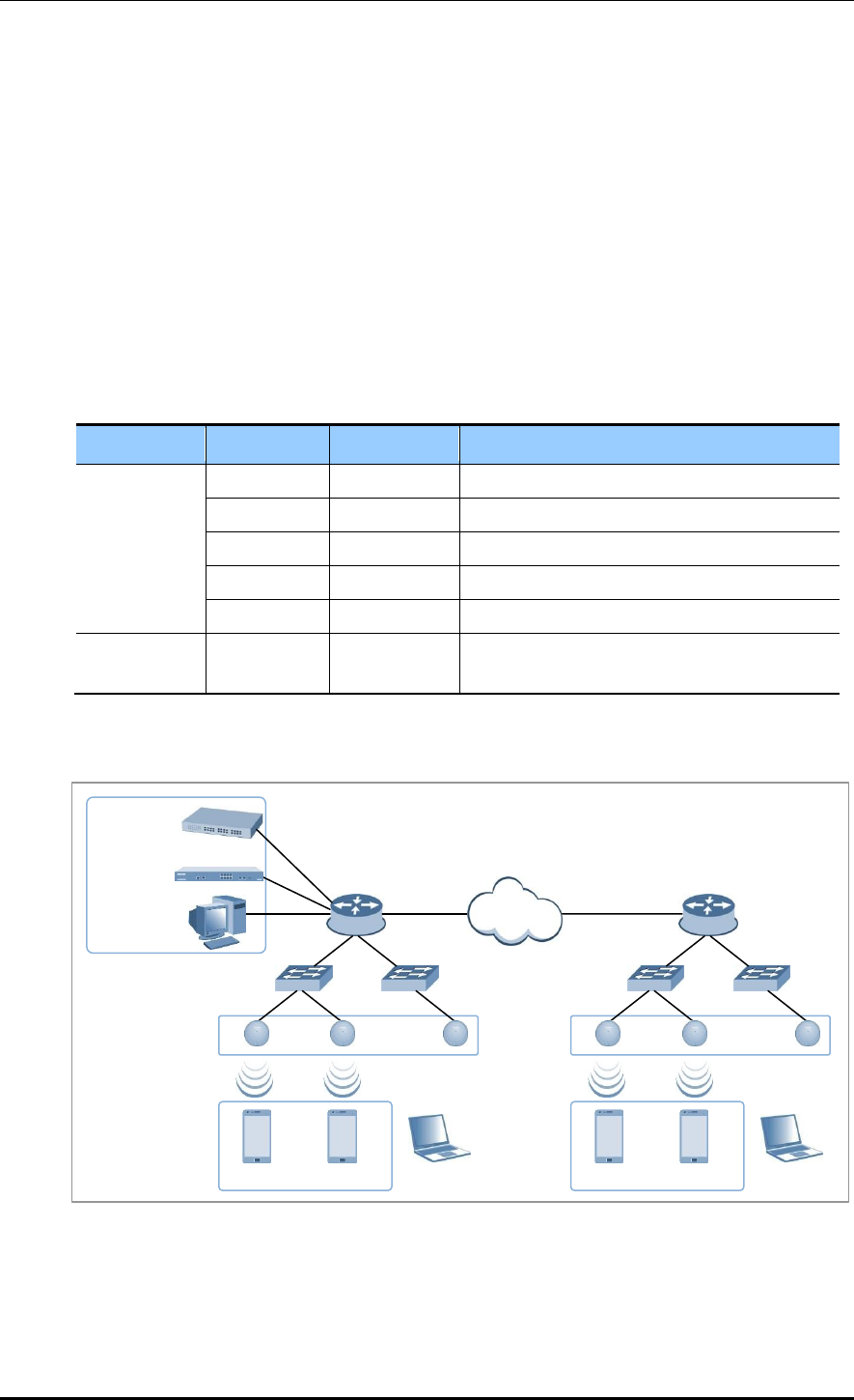
CHAPTER 1. Access Point Controller System Overview
© SAMSUNG Electronics Co., Ltd. page 39 of 628
1.5 NAT Configuration between AP and APC
The APC system provides the same services even when the APC or AP is in a NAT
environment.
If the APC system is in a NAT environment and obtaining a public IP address is difficult,
the APC can be configured to use a private IP address by enabling port mapping on the
existing NAT equipment, so that it can provide services to APs on the public IP network
and APs existing under other NAT networks.
Using this feature requires that the NAT equipment be applied with the following port
settings:
Service
TCP Port
UDP Port
Description
General
20, 21
-
FTP Server
22
-
Secure Shell
23
-
Telnet
80, 443
-
HTTP Web Server
123
123
NTP
AP-APC
Connection
-
5246, 5247
CAPWAP
An example of service configuration diagram for the NAT environment is illustrated below.
Figure 16. AP-APC NAT Environment Configuration Diagram
IP-PBX
WEC8050/
WEC8500
WEM
Router
Internet
…
…
FMC Client
Router
…
…
FMC Client
W-EP AP
W-EP AP

CHAPTER 2. Basic System Configuration
© SAMSUNG Electronics Co., Ltd. page 40 of 628
CHAPTER 2. Basic System
Configuration
In this chapter, the basic system configuration using web and Command Line Interface
(CLI) is introduced and how to use CLI and Web UI is described.
2.1 Basic System Configuration
2.1.1 CLI Connection
Connecting to APC using CLI is as follows:
Direct connection to the system console port
Telnet or SSH connection through an Ethernet port
When the booting of APC is completed, log into the system as follows:
1) For the first connection, log in using ID: ‘samsung’ and Password: ‘samsung’.
USERNAME : samsung
PASSWORD : samsung
THIS IS YOUR FIRST LOGIN AFTER USER ACCOUNT HAS BEEN CREATED.
YOU MUST CHANGE YOUR PASSWORD.
ENTER LOGIN PASSWORD : samsung
ENTER NEW PASSWORD : ********
CONFIRM NEW PASSWORD : ********
PASSWORD SUCCESSFULLY CHANGED
WEC8500 #
2) After the first login, you must change the password. Use the changed password for the
next login.
The default ID of APC is set to ‘samsung’ that has an administrator privilege.

CHAPTER 2. Basic System Configuration
© SAMSUNG Electronics Co., Ltd. page 41 of 628
2.1.2 Managing Operator Account
An operator who has an administrator privilege (level 1) can create or delete a new operator
account. When creating an account, specify the account’s privilege level (level 1-4).
To set up operator account related functions, go to configure mode by executing the
following command.
WEC8500# configure terminal
WEC8500/configure #
Adding or deleting an account
The commands used to create or delete an account are as follows:
mgmt-user [USERNAME] [USERLEVEL] description [DESCRIPTION]: Adds a user
no mgmt-user [USERNAME]: Deletes a user
Parameter
Description
USERNAME
User ID
USERLEVEL
User level
DESCRIPTION
Adds user information
WEC8050/configure# mgmt-user test 1 description “test account”
PASSWORD : *********
CONFIRM PASSWORD : *********
USER(test) CREATED.
WEC8050/configure# no mgmt-user test
user(test) deleted.
Retrieving account information
To check user account information use the ‘show mgmt-users’ command.
Changing Password
Use the ‘password’ command to change the password for your account.
The ‘password’ command must be executed in the highest user mode.
WEC8500# password
CURRENT PASSWORD : ********
NEW PASSWORD : ********
CONFIRM NEW PASSWORD : ********
CHAPTER 2. Basic System Configuration
© SAMSUNG Electronics Co., Ltd. page 42 of 628
2.1.3 APC Management Port Configuration
To connect to the APC remotely using telnet/SSH or web, it is necessary to set up an IP
address to the management port.
Set up the management port as follows:
1) Go to configure ‘mgmt0’ interface configuration mode of CLI.
WEC8500# configure terminal
WEC8500/configure# interface mgmt0
2) Set up an IP address.
WEC8500/configure/interface mgmt0# ip address 100.100.100.1/24
In case of WEC8050, there is no management (mgmt0) port. After establishing an
IP address in one of ports ge1 to ge4 by referring to the contents of 'Port
Configuration' and then using the CLI, connect the Ethernet cable to the port.
2.1.4 SNMP Community Configuration
To connect to the web server of APC, it is necessary to add Simple Network Management
Protocol (SNMP) community through CLI. For more information, see ‘10.1 SNMP
Configuration’.
2.1.5 CLI Basic Usage
The CLI is a text command based interface used to change or retrieve the system settings.
Several users can change the settings at the same time using the CLI of the same system.
Because privilege per user is already configured, a user can execute a command allowed by
the user’s privilege. Various commands are available for each system function. For more
information, see ANNEX ‘CLI Command Structure’.
Command Help
The CLI provides a help for all the commands. To see a help for a command and parameter,
enter ‘?’. Based on an input character, it shows a help for a command or parameter that can
be entered.
Category
Description
?
Displays the command list and help at the current level
Command ?
Displays the parameter and help required for a command

CHAPTER 2. Basic System Configuration
© SAMSUNG Electronics Co., Ltd. page 43 of 628
A usage example is given below.
WEC8500# show ?
80211a Display 802.11a network settings
80211bg Display 802.11bg network settings
80211h Display 802.11h configuration
access-list List IP access lists
alarm Show alarm information
ap Show ap information
ap-debug Show ap debug information
...
vap Show vap information
version Show package version information
vlan Display VLAN information
vqm Show vqm command
vrrp VRRP information
wids Wids command
wips Wips command
wireless-acl-list Show wireless-acl-list
wlan Show wlan information
WEC8500#
Command automatic completion function
The CLI supports the command automatic completion function using the TAB key.
When you press the TAB key after entering the first few characters of a command, the rest
characters of the command that starts with the entered characters is automatically entered.
If there are several commands that start with the entered characters, press the TAB key to
jump to the next command. The below example shows the ‘show’, ‘save’, or ‘ssh’
command is entered in order by entering ‘s’ and pressing the TAB key.
WEC8500# s
[When the TAB key is pressed]
WEC8500# show
[When the TAB key is pressed once again]
WEC8500# save

CHAPTER 2. Basic System Configuration
© SAMSUNG Electronics Co., Ltd. page 44 of 628
Command error
When a command that is not supported by the system is entered, an error message is
displayed.
WEC8500# command-unknown
^
Error : Command ‘command-unknown’ does not exist
When a parameter that is not supported by a command is entered, an error message
according to the situation is displayed.
WEC8500# configure test
^
% Invalid parameter (mandatory)
Command modes
When the ‘exit’ command is entered, the mode is changed to the upper command mode.
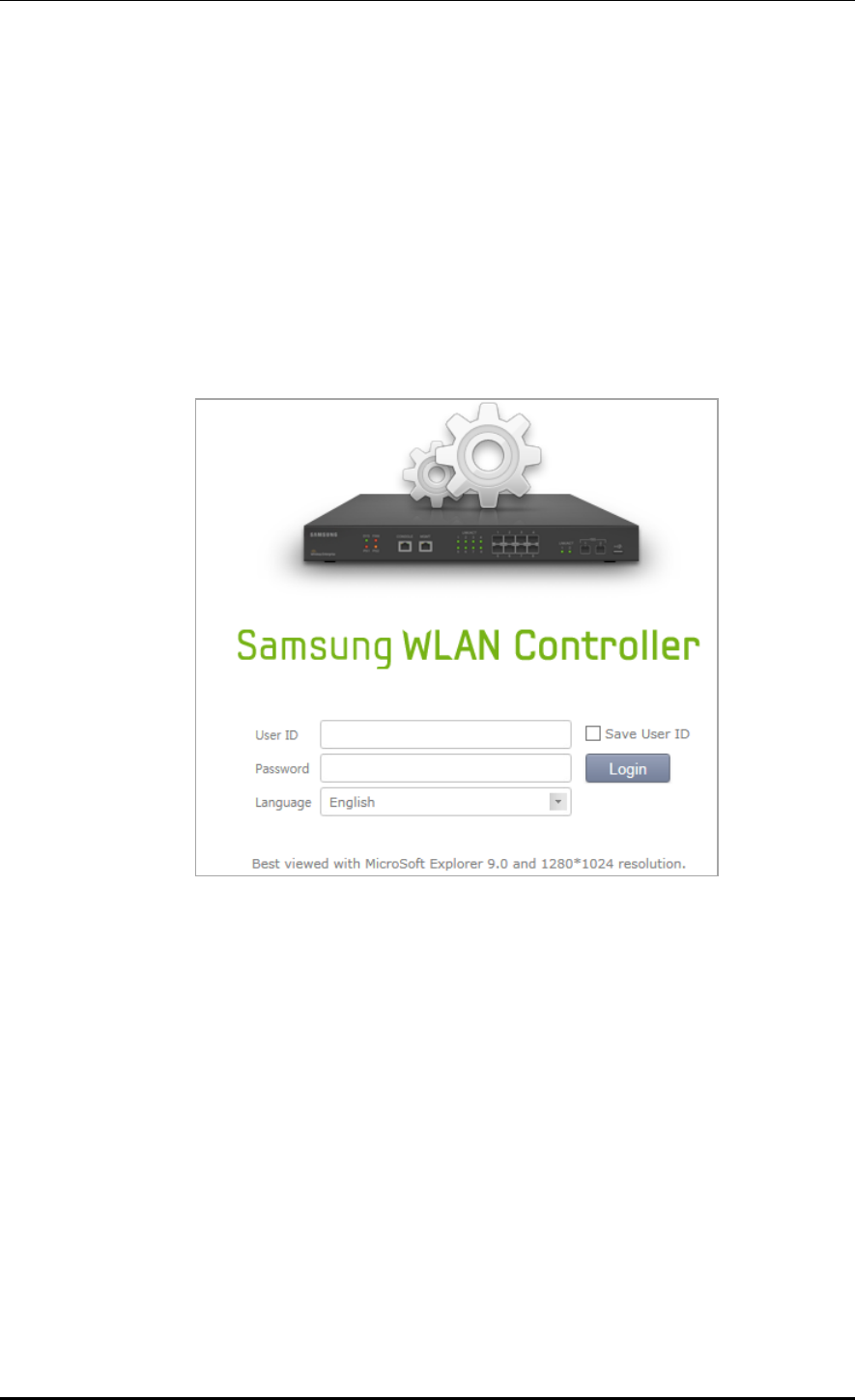
CHAPTER 2. Basic System Configuration
© SAMSUNG Electronics Co., Ltd. page 45 of 628
2.2 Using Web UI
2.2.1 Web UI Connection
To use the WEC, i.e. Web UI of APC system, the IP address of ethernet port must be set up.
When connecting to the IP address of APC ethernet port in a web browser, the below login
window is displayed. Log in using a default connection account ‘samsung’.
After the first login, you go through the course of changing the password. If you have
changed the password by connecting to the CLI, you don't have to go through the course of
changing the password.
Figure 17. Web UI Connection Window
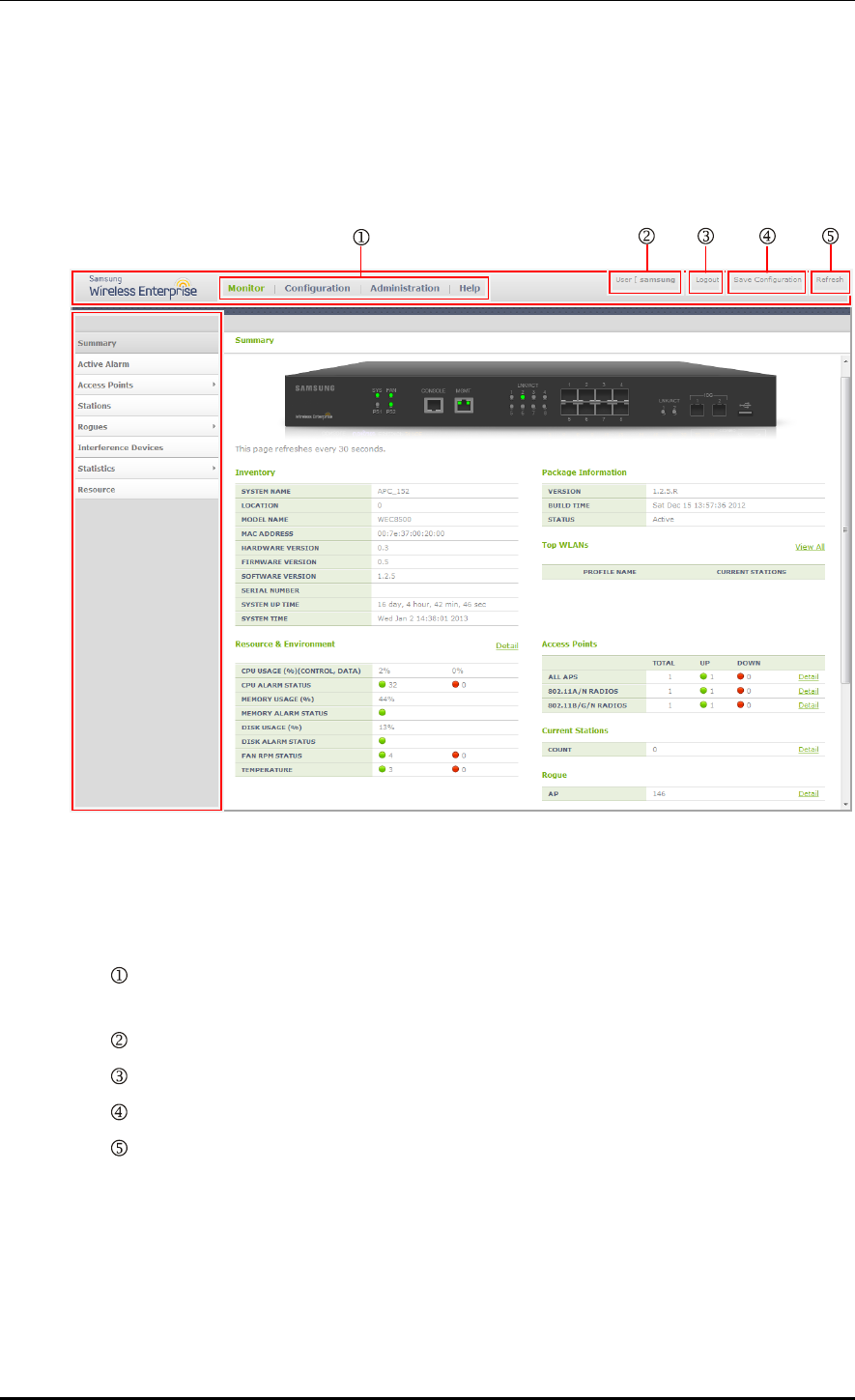
CHAPTER 2. Basic System Configuration
© SAMSUNG Electronics Co., Ltd. page 46 of 628
2.2.2 WEC Main Window
The WEC Main window consists of menu bar, sub-menus, and detail windows of each
menu.
Figure 18. WEC Main Window
Menu bar
The menu bar consists of the following items:
: Provides detail configuration or retrieval function for each item. When you select
each item, lower menus in the sub-menus area are displayed.
: Displays a user login ID.
: Logs out from the WEC.
: Saves the current configuration information into the system.
: Refreshes the screen.
Sub-menus
This provides the detail menus for Monitor, Configuration, Administration, or Help in the
menu bar.
Sub-menu
Menu bar
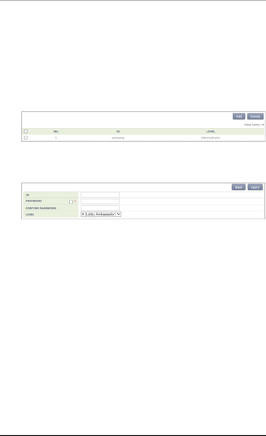
CHAPTER 2. Basic System Configuration
© SAMSUNG Electronics Co., Ltd. page 47 of 628
2.2.3 Managing Operator Account
To add a operator account in Web UI, follow the below procedure.
In the menu bar of <WEC Main window>, select <Administration> and then select
<Local Management Users> menu in the sub menu. The subtree shows the <APC> and
<AP> menu items. Select <APC>.
You can add or delete a operator account in the WEC.
Figure 19. Operator Account Management Window
1) To add an account, click the <Add> button.
Figure 20. Operator Account Addition Window
2) Enter an item according to each parameter description, and click the <Apply> button.
ID: Username to add
PASSWORD: User’s initial password
CONFIRM PASSWORD: Re-enter the initial password
LEVEL: User privilege
1 (Administrator): Administrator privilege that allows to execute all the
commands
2 (Operator): Can change system configuration.
3 (Monitor): Can retrieve system status.
4 (Lobby Ambassador): Temporary user

CHAPTER 2. Basic System Configuration
© SAMSUNG Electronics Co., Ltd. page 48 of 628
2.3 Initial Setup Wizard
2.3.1 Overview
The initial setup wizard aims to finish the basic settings by guiding the settings required for
the basic WLAN service in order when the APC is installed. It supports only the basic
settings to operate the WLAN service and the settings which are additional or are not
frequently used are not supported here. They must be made through the general WEC
screen.
2.3.2 Connecting
Connecting condition
If being connected to the WEC as web UI at the factory reset state or while there is no
WLAN, the APC system is connected to the Initial Setup Wizard instead of the general
WEC screen.
Connecting at the factory reset state
The connection at the factory reset state is available through the management port.
1) Connect the Ethernet cable to the management port and then to the PC.
2) The default IP address of the management port is 192.168.1.2. After configuring the IP
address of the PC fit for the bandwidth, open the web browser.
3) Enter 192.168.1.2 in the address bar of the browser to access.
In case of WEC8050, there is no management (mgmt0) port. After establishing
the IP address in one of ports ge1 to ge4 by using the CLI first on reference to
‘3.1 Port Configuration’, connect the Ethernet cable to the port.
Access while the IP address is set
If the IP address of the APC is set, check whether the APC and the PC are networked and
then open the web browser before accessing the IP address.
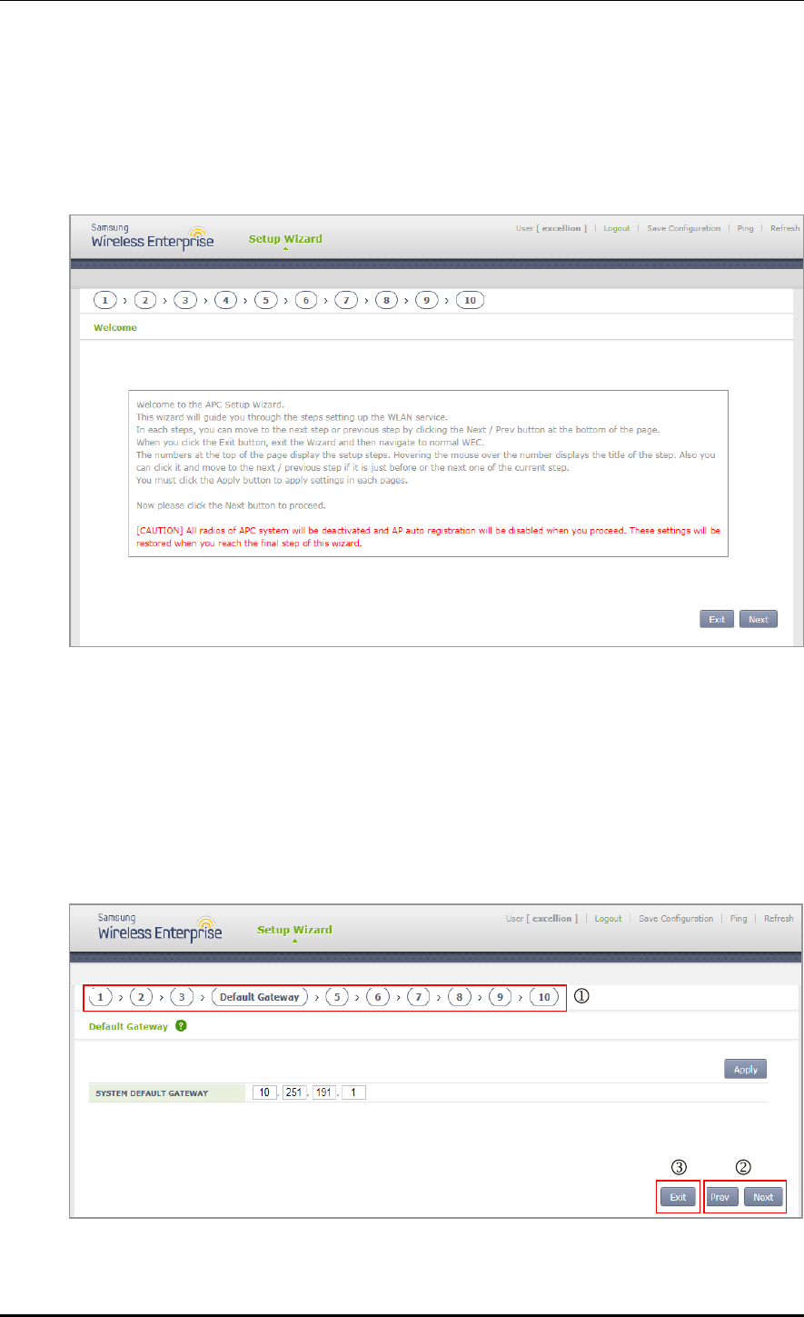
CHAPTER 2. Basic System Configuration
© SAMSUNG Electronics Co., Ltd. page 49 of 628
2.3.3 How to Use
If the access to the APC is made through the web browser, follow the login procedure as
shown in ‘2.2.1 Web UI Connection’. After that, you can see the Welcome message by
connecting to the wizard.
Figure 21. Initial Setup Wizard Welcome Screen
Press the Next button to move to the configuration step 1 and then start the basic settings.
Press the Exit button to close the wizard and then move to the general WEC screen.
Start the wizard and then deactivate all wireless communications of the APC system as well
as the function of automatically registering the AP. The settings are recovered at the last
step of the wizard.
Description on the Screen
Figure 22. Move to the setup step of the initial setup wizard

CHAPTER 2. Basic System Configuration
© SAMSUNG Electronics Co., Ltd. page 50 of 628
: Show the current setup step and the whole setup step by being located on the top of the
screen. When you hover the mouse over each number, it shows the name of the step and
you can click to move to the step just before or after the current step.
: When you press the Next button, you move to the next setup step and when you press
the Prev button, you return to the previous setup step.
: Press the Exit button to close the wizard and then move to the general WEC screen. In
the case, you cannot return back to the initial setup wizard screen. If the APC restarts
while the WLAN is not created, you can go to the wizard screen again.
Setup Step
The initial setup wizard consists of the following setup steps: After setting up the
description desired on each screen, click the Apply button to apply the modifications to the
system.
1) General setup:
Set up basic information including the name, location, contact number, etc. of the
system.
Set up the basic country code and the basic environment.
Set up the system time and the time zone. Click the PC TIME button to change the
time of the APC by setting to the time of the PC.
2) Interfaces:
Create interfaces. For more information, refer to '3.2.1 Interface Management' and
‘3.3.1 VLAN’.
3) Interface groups:
Create interface groups and assign the interfaces created at the previous step.
For more information, refer to ‘3.2.2 Managing Interface Group’
4) Default Gateway:
Set up a default gateway of the system. The default gateway is a default path to be
used when the APC communicates with another equipment on the TCP/IP network.
5) WLAN:
Create a WLAN. For more information, refer to ‘5. WLAN Management’.
If the L2 Security Type corresponds to one of the following conditions, move to the
step of setting up a RADIUS server. For more information on creating a RADIUS
server, refer to ‘8.1.1 External RADIUS Server’.
(1) 802.1x
(2) Static WEP + 802.1x
(3) +WPA2 and enabled 802.1x
6) DHCP proxy:
When an external DHCP server is used, configure settings of proxy or relay.
7) DHCP internal server:
Configure a DHCP internal server. For more information, refer to ‘5.4.1 DHCP
Server’.

CHAPTER 2. Basic System Configuration
© SAMSUNG Electronics Co., Ltd. page 51 of 628
8) DNS:
The APC gets DNS information from a DNS server and provides the DNS relay
function that relays the DNS server and a client. If a DNS server is connected to the
APC and a UE connected to the APC configures the DNS server as the APC, the
DNS service can be received.
9) NTP:
If the APC is configured as a NTP client, it receives the Coordinated Universal
Time (UTC) information from the configured NTP server and synchronizes the
local time.
10) Finish:
Finish the basic settings to configure the WLAN of the APC and then close the
wizard.
CHAPTER 3. Data Network Function
© SAMSUNG Electronics Co., Ltd. page 52 of 628
CHAPTER 3. Data Network Function
In this chapter, how to set up the data network functions of APC including VLAN, link
aggregation, and layer 3 protocol is described.
3.1 Port Configuration
The APC port is configured with a physical interface.
Physical interface of 11 ports except WEC8500 console port
Physical interface of 4 ports except WEC8050 console port
3.1.1 Port management
The WEC8500 Management port is used to manage the WEC8500. It does not
support VLAN and its interface name is ‘mgmt0’. The 8 ports at the right side of
Management port are 10/100/1000 BASE T-ports and their names are GE1-8.
To the right side of the 10/100/1000 BASE T-ports, there are two Gigabit ports, i.e.
XE1 and XE2. In case of WEC8050, there is no management (mgmt0) port. After
establishing the IP address in one of ports ge1 to ge4 by using the CLI first,
connect the Ethernet cable to the port.
Configuration using CLI
To configure the port related function, enter into the interface mode by entering the
‘interface [INTERFACE_NAME]’ command in the configure mode.
An example of entering into the interface setup mode of the management port is shown
below.
WEC8500# configure terminal
WEC8500/configure# interface mgmt0
WEC8500/configure/interface mgmt0#

CHAPTER 3. Data Network Function
© SAMSUNG Electronics Co., Ltd. page 53 of 628
The port related CLI commands are as follows:
[auto-nego, speed, duplex]
The commands used to configure an auto-nego, speed, and duplex addresses are shown
below. To delete the configuration, enter the ‘no’ parameter.
WEC8500/configure/interface ge1# speed-duplex ?
10-full Set 10Mb/s full-duplex
10-half Set 10Mb/s half-duplex
100-full Set 100Mb/s full-duplex
100-half Set 100Mb/s half-duplex
1000-full Set 1000Mb/s full-duplex
1000-half Set 1000Mb/s half-duplex
auto-nego Set auto negotiation speed/duplex
[admin status]
This is a command that makes the port not working. The ‘no’ parameter is used to restart
the port.
shutduown
no shutdown
[flow control]
This is a command that operates flow control to the port. The ‘no’ parameter is used to stop
the flow control.
flowcontrol on
no flowcontrol on
[switch port]
This is a command that changes the port to the L2 mode. The ‘no’ parameter is used to
change it to the L3 mode.
switchport
no switchport
[ip address]
This is a command that configures a static IP address. To delete the configuration, enter the
‘no’ parameter.
ip address {A.B.C.D/mask length}
no ip address {A.B.C.D} {A.B.C.D}
no ip address {A.B.C.D/mask length}
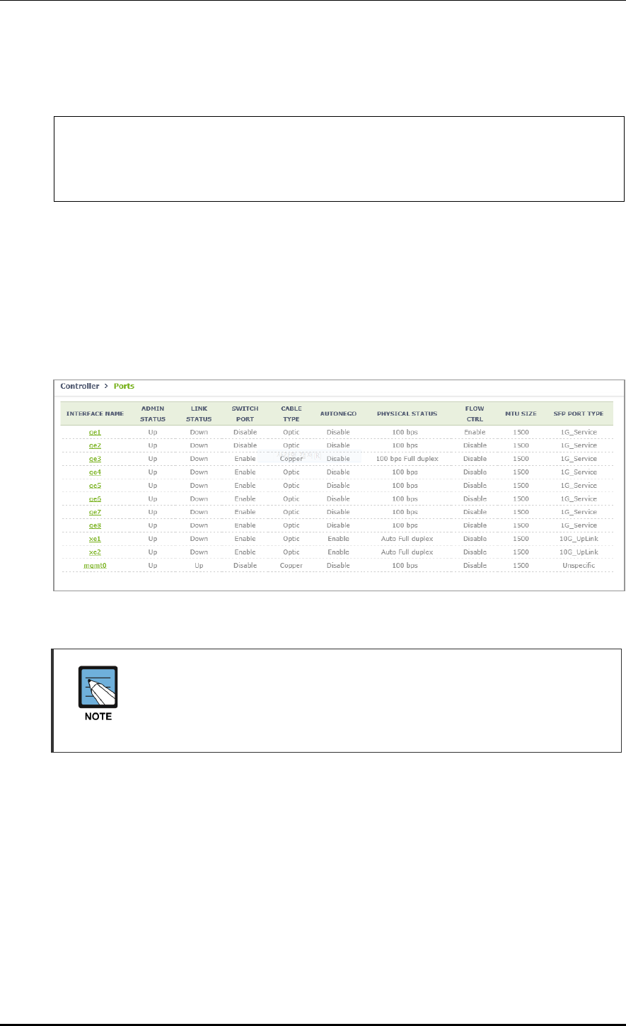
CHAPTER 3. Data Network Function
© SAMSUNG Electronics Co., Ltd. page 54 of 628
Below is an example of port setting to enter the initial setup wizard upon the initial
installation of WEC8050.
WEC8500/configure/interface ge1# no shutdown
WEC8500/configure/interface ge1# flowcontrol on
WEC8500/configure/interface ge1# no switchport
WEC8500/configure/interface ge1# ip address 192.168.1.2/24
Configuration using Web UI
In the menu bar of <WEC Main window>, select <Configuration> and then select the
<Controller> <Ports> menu in the sub-menus. Operator can configure the ports.
The Ports initial window is shown below.
Operator can check the current status of each port.
Figure 23. Port Management Window
The auto-nego, speed, or duplex can be configured only when the cable type is
Copper.
They cannot be configured if the cable type is Optic (The auto-nego should
always be enabled whether the cable type is copper or optic).
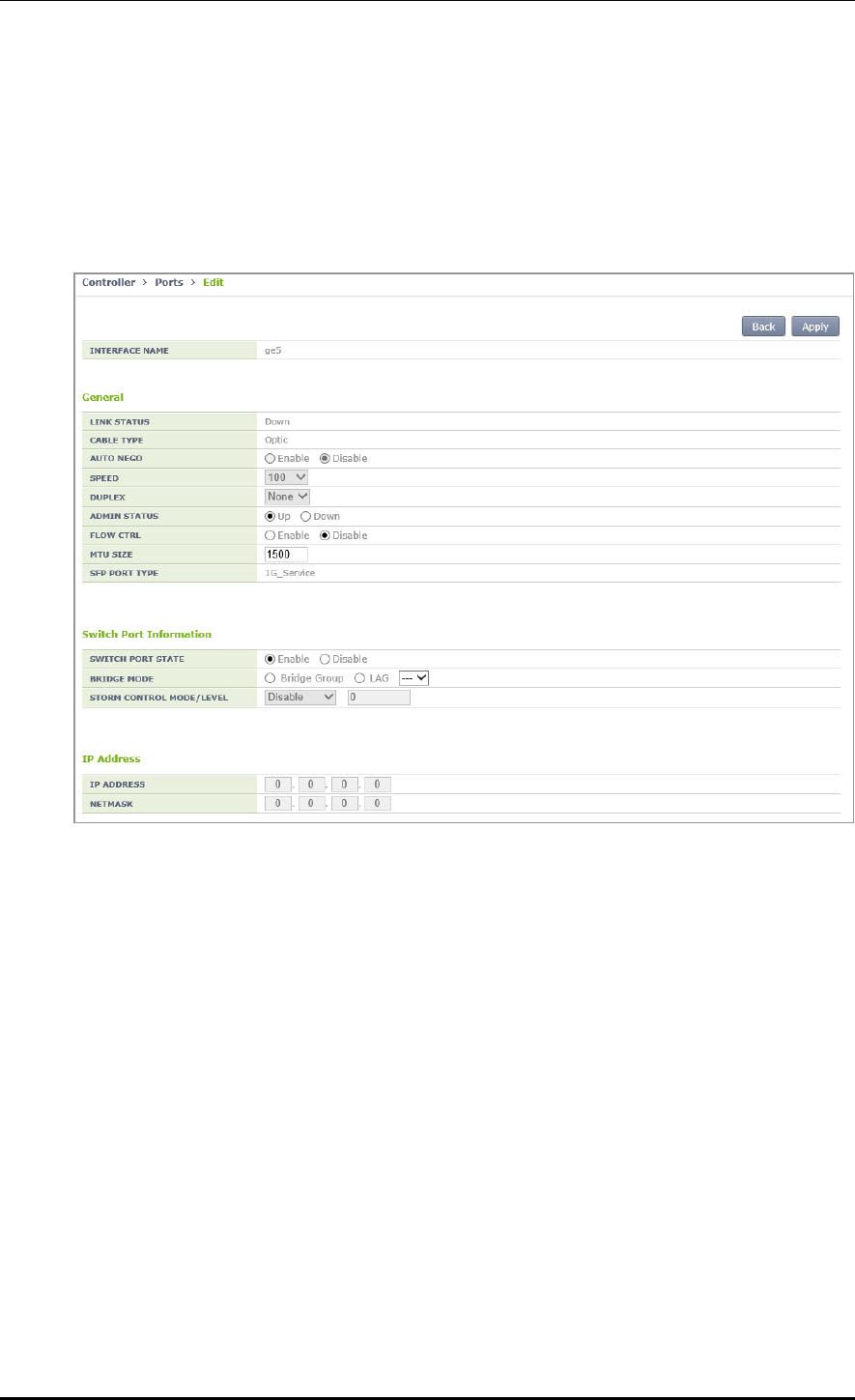
CHAPTER 3. Data Network Function
© SAMSUNG Electronics Co., Ltd. page 55 of 628
[Port Configuration Change]
1) In the Ports initial window, click the <INTERFACE NAME> button to go to port
configuration change window.
2) In the port configuration change window, the auto-nego, speed, duplex, admin status,
flow control, mtu size, switch port, or ip address, etc. can be configured.
Figure 24. Port Configuration Change Window
CHAPTER 3. Data Network Function
© SAMSUNG Electronics Co., Ltd. page 56 of 628
3.2 Interface Configuration
The WEC8500 interface consists of the following physical interface and virtual interface.
Physical interface of 11 ports except console port
1024 virtual interfaces using VLAN
There are two types of WEC8050 interface as shown below; physical interface and virtual
interface.
Physical interface of 4 ports except console port
128 virtual interfaces using VLAN
3.2.1 Interface management
The WEC8500 Management port is used to manage the WEC8500. It does not
support VLAN and its interface name is ‘mgmt0’. The 8 ports at the right side of
Management port are 10/100/1000 BASE T-ports and their names are GE1-8.
To the right side of the 10/100/1000 BASE T-ports, there are two Gigabit ports, i.e.
XE1 and XE2.
Configuration using CLI
To configure the interface related function, go to the interface mode by entering the
‘interface [INTERFACE_NAME]’ command in the configure mode. An example of
entering into the interface mode of the management port is shown below.
WEC8500# configure terminal
WEC8500/configure# interface mgmt0
WEC8500/configure/interface mgmt0#
The interface related CLI commands are as follows:
[ip address]
This is a command that configures a static IP address. The ‘no’ parameter is used to delete
the configuration.
ip address {A.B.C.D/mask length}
no ip address {A.B.C.D} {A.B.C.D}
no ip address {A.B.C.D/mask length}
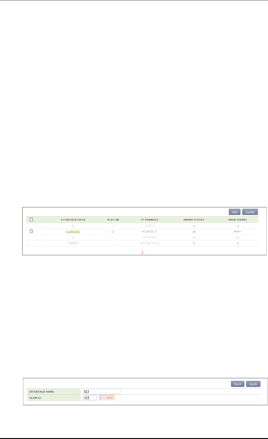
CHAPTER 3. Data Network Function
© SAMSUNG Electronics Co., Ltd. page 57 of 628
[ip address dhcp]
This is a command that configures a dynamic IP address using DHCP. The ‘no’ parameter
is used to delete the configuration.
ip address dhcp
no ip address dhcp
[shutdown]
This is a command that makes the interface not working. The ‘no’ parameter is used to
restart the interface.
shutdown
no shutdown
Configuration using Web UI
In the menu bar of <WEC Main window>, select <Configuration> and then select the
<Controller> <Interfaces> menu in the sub-menus. You can configure an interface and
VLAN.
The Interface initial window is shown below.
Figure 25. Interfaces Window (1)
[Adding VLAN]
1) In the Interface initial window, click the <Add> button to go to VLAN creation
window.
2) Enter an INTERFACE NAME and VLAN ID in the VLAN creation window.
The INTERFACE NAME describes a VLAN to create and English characters without
a space, numbers, and ‘_’ can be used. The VLAN ID is the number from 1 to 4094
and it specifies a unique VLAN value.
Click the <Apply> button to go to detail configuration screen.
Figure 26. Interfaces Window (2)
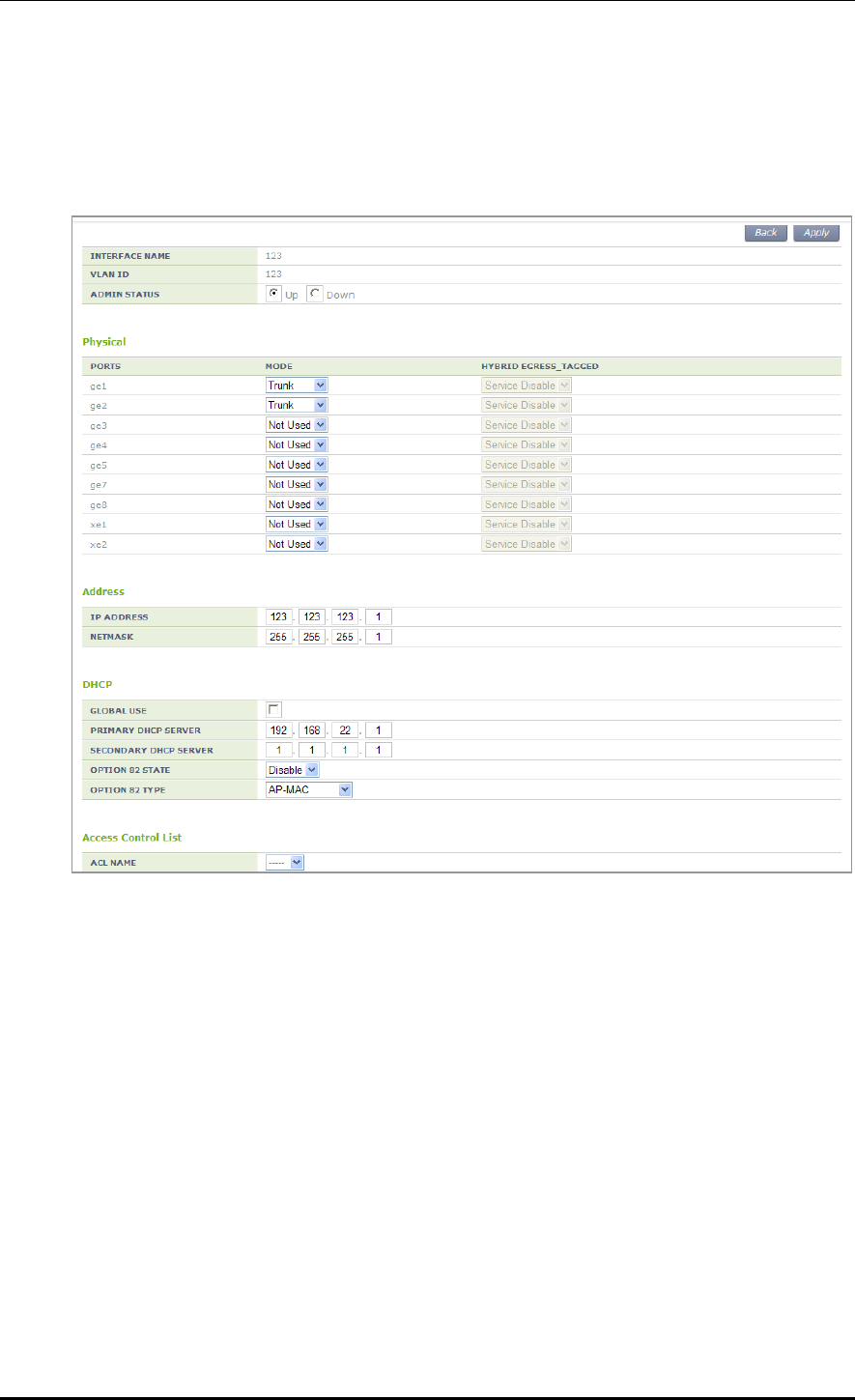
CHAPTER 3. Data Network Function
© SAMSUNG Electronics Co., Ltd. page 58 of 628
3) Perform detail configuration in the VLAN detail configuration window.
If you specify PRIMARY DHCP SERVER or SECONDARY DHCP SERVER in the
DHCP area, you can specify the configuration of a DHCP server.
After configuration, click the <Apply> button to apply it to the system.
Figure 27. Interfaces Window (3)
[Deleting VLAN]
In the Interface initial window, click the <Delete> button to delete a selected VLAN.
The select VLAN cannot be deleted if it is being used in the system.
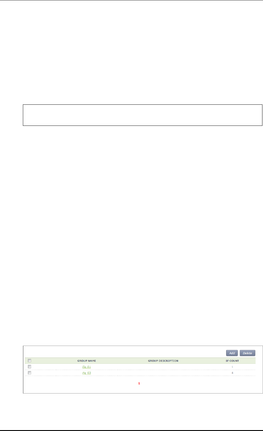
CHAPTER 3. Data Network Function
© SAMSUNG Electronics Co., Ltd. page 59 of 628
3.2.2 Managing Interface Group
To use WLAN and other services, it is necessary to configure an interface into an interface
group.
Configuration using CLI
An example of entering into the group configuration mode of ifg_01 interface is shown
below.
WEC8500# configure terminal
WEC8500/configure# if-group ifg_01
Interface Group related commands are as follows:
[Creating or Deleting Interface group]
This command creates an interface group. Use ‘no’ parameter to delete an interface group.
if-group [INTERFACE_GROUP_NAME]
no if-group [INTERFACE_GROUP_NAME]
[Adding or deleting Interface]
This command adds an interface to an interface group being configured. Use ‘no’
parameter to delete an interface.
add-if[INTERFACE_IP_ADDRESS]
no add-if[INTERFACE_ IP_ADDRESS]
[Retrieving Interface Group Status]
This command retrieves the configuration status of an interface group.
show if-group
Configuration using Web UI
In the menu bar of <WEC Main window>, select <Configuration> and then select the
<Controller> <Interfaces Groups> menu in the sub-menus. Click the <Add> or
<Delete> button to add or delete an interface group.
Figure 28. Interface Group Window (1)
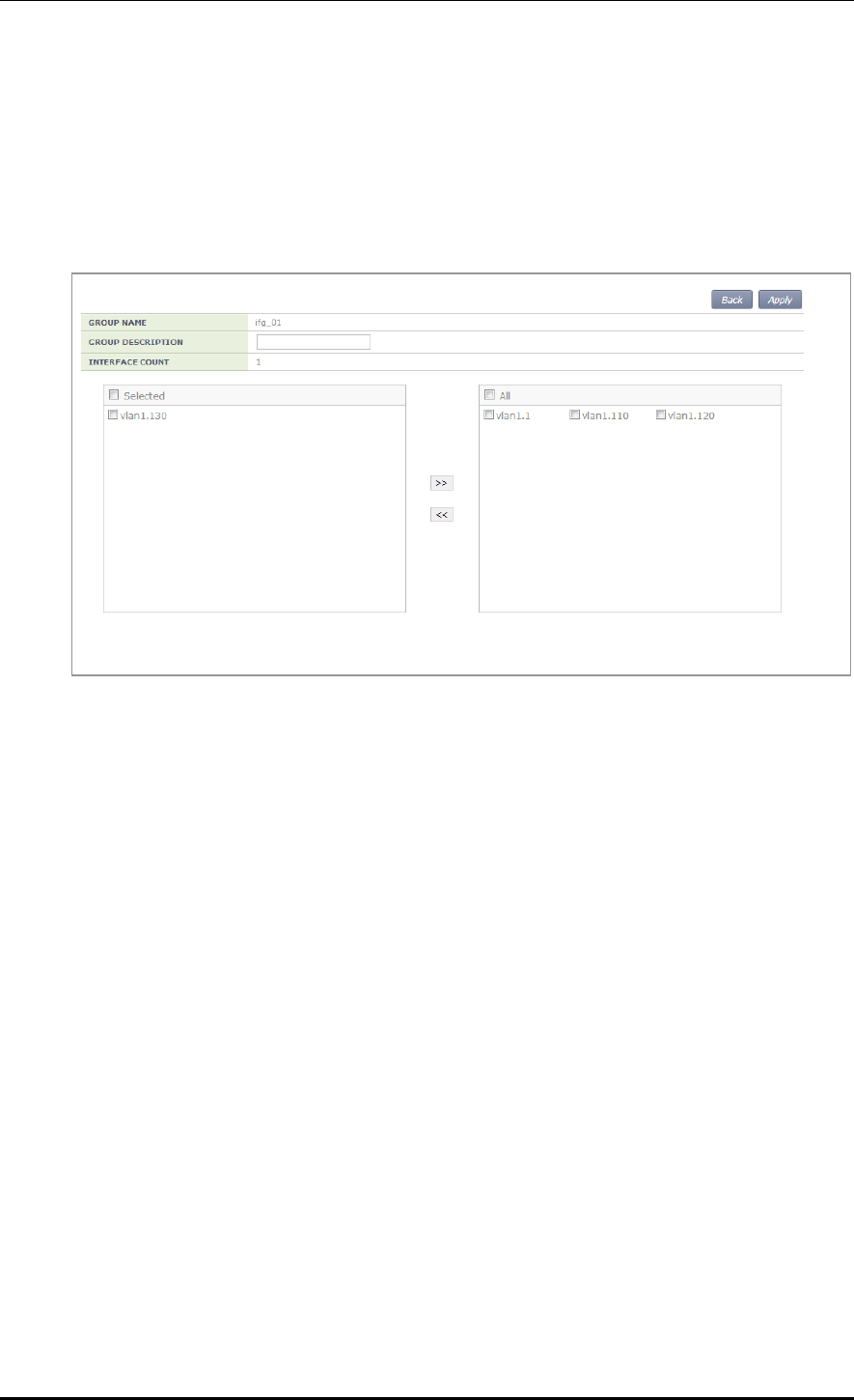
CHAPTER 3. Data Network Function
© SAMSUNG Electronics Co., Ltd. page 60 of 628
Follow the below procedure to add an interface group.
1) In the Interface group initial window, click the <Add> button.
2) Enter information on GROUP NAME and GROUP DESCRIPTION and then add or
delete an interface to or from an interface group.
Figure 29. Interface Group Window (2)
3) Click the <Apply> button to apply the configuration.

CHAPTER 3. Data Network Function
© SAMSUNG Electronics Co., Ltd. page 61 of 628
3.3 VLAN Configuration
3.3.1 VLAN
Configuration using CLI
To configure VLAN, go to the VLAN interface mode by executing the following command.
WEC8500# configure terminal
WEC8500/configure# interface vlan
WEC8500/configure/interface vlan#
The related command is shown below and the range of VLAN ID is 1-4094.
[vlan bridge]
This command creates VLAN. The ‘no’ parameter is used to delete VLAN.
vlan [VLAN_ID] bridge 1
no vlan [VLAN_ID] bridge 1
[switchport access vlan]
This command set the VLAN mode to the access or hybrid mode. The ‘no’ parameter is
used to delete the VLAN configuration.
switchport {access/hybrid} vlan [VLAN_ID]
[switchport mode]
This command configures the mode of switch port. The ‘no’ parameter is used to delete the
configuration.
switchport mode {access/hybrid/trunk}
no switchport mode
[switchport hybrid allowed vlan]
This command configures the mode of switch port to hybrid. The ‘no’ parameter is used to
delete the configuration.
switchport hybrid allowed vlan: Configures VLAN to hybrid.
switchport hybrid allowed vlan all: Configures all the allowed VLANs to hybrid.
switchport hybrid allowed vlan none: Stops VLAN data transmission/reception.
switchport hybrid allowed vlan add [VLAN_ID]: Adds VLAN to the hybrid mode.
switchport hybrid allowed vlan remove [VLAN_ID]: Deletes VLAN from the hybrid
mode.
no switchport hybrid vlan: Deletes all the hybrid settings.

CHAPTER 3. Data Network Function
© SAMSUNG Electronics Co., Ltd. page 62 of 628
[switchport trunk allowed vlan]
This command configures the mode of switch port to trunk. The ‘no’ parameter is used to
delete the configuration.
switchport trunk allowed vlan: Configure VLAN to the trunk mode.
switchport trunk allowed vlan all: Configure all the VLANs to the trunk mode.
switchport trunk allowed vlan none: Stops VLAN data transmission/reception.
switchport trunk allowed vlan add [VLAN_ID]: Adds VLAN to the trunk mode.
switchport trunk allowed vlan remove [VLAN_ID]: Removes VLAN with the trunk mode.
no switchport trunk vlan: Removes all the trunk settings.
[show vlan]
This command retrieves VLAN configuration status.
show vlan [VLAN_ID]: Displays specific VLAN information.
show vlan all bridge 1: Displays all the VLAN information.
show vlan brief: Displays all the VLAN information briefly.
show vlan dynamic bridge 1: Displays dynamic VLAN information.
show vlan static bridge 1: Displays static VLAN information.
[Typical configuration procedure]
The typical configuration procedure of VLAN is as follows:
WEC8500# configure terminal
WEC8500/configure# bridge 1 protocol mstp
WEC8500/configure # vlan database
WEC8500/configure/vlan#vlan {2-4094} bridge 1
WEC8500/configure/vlan# exit
WEC8500/configure# interface vlan1.{2-4094}
Configuration using Web UI
In the menu bar of <WEC Main window>, select <Configuration> and then select the
<Controller> <Interfaces> menu in the sub-menus.
For more information about configuration procedure, see ‘3.2.1 Interface Management’.

CHAPTER 3. Data Network Function
© SAMSUNG Electronics Co., Ltd. page 63 of 628
3.3.2 Bridge
To set up bridge related functions, go to configure mode by executing the following
command
WEC8500# configure terminal
The bridge related commands are as follows:
[bridge address]
This command configures a bridge address. The ‘no’ parameter is used to clear the
configuration.
bridge 1 address [MAC] [forward/discard] [IFNAME]
no bridge 1 address [MAC] [forward/discard] [IFNAME]
Parameter
Description
MAC
MAC address. Entered in the format of HHHH.HHHH.HHHH.
forward/discard
- forward: Configures forward matching frame.
- discard: Configures discard matching frame.
IFNAME
Interface name of a bridge.
[bridge ageing time]
This command configures the age-out time of a bridge. The ‘no’ parameter is used to clear
the configuration.
bridge-group 1 ageing-time [AGEINGTIME]
no bridge-group 1 ageing-time
Parameter
Description
AGEINGTIME
age-out time (range: 10-1000000 s)
[bridge protocol]
This command creates a bridge in one of the IEEE 802.1Q Spanning-Tree Protocol (STP),
IEEE802.1s multiple STP (MSTP), or IEEE 802.1W Rapid STP (RSTP) protocol.
bridge 1 protocol [PROTOCOL]
no bridge 1 protocol
Parameter
Description
PROTOCOL
Protocol to configure (ieee/mstp/rstp)
- ieee: STP
- mstp: MSTP

CHAPTER 3. Data Network Function
© SAMSUNG Electronics Co., Ltd. page 64 of 628
Parameter
Description
- rstp: RSTP
[clear mac address-table]
This command deletes the filtering database of a default bridge.
clear mac address-table [OPTION] [KIND] [WORD]
Parameter
Description
OPTION
Filtering database option (static/multicast)
- static: Filtering database item that is configured as static
- multicast: Filtering database item that is automatically configured by
the multicast protocol
KIND
Filtering database type (address/vlan/interface)
- address: Filtering database using a MAC address
- vlan: Filtering database using the VLAN information.
- interface: Filtering database using the interface information
WORD
Option
[clear mac address-table dynamic]
This command deletes bridge operation among the filtering database of a default bridge.
clear mac address-table dynamic [KIND] [WORD]
Parameter
Description
KIND
Filtering database type (address/vlan/interface)
- address: Filtering database using a MAC address
- vlan: Filtering database using the VLAN information.
- interface: Filtering database using the interface information
WORD
Option
[clear mac address-table dynamic bridge]
This command deletes the filtering database of bridge operation.
clear mac address-table dynamic bridge [BRIDGE_NAME]
clear mac address-table dynamic [address/interface/vlan] [WORD] bridge [NAME]
Parameter
Description
KIND
Filtering database type (address/vlan/interface)
- address: Filtering database using a MAC address
- vlan: Filtering database using the VLAN information.
- interface: Filtering database using the interface information
WORD
Option
BRIDGE_NAME
Bridge name

CHAPTER 3. Data Network Function
© SAMSUNG Electronics Co., Ltd. page 65 of 628
[show bridge]
This command retrieves bridge information.
show bridge
[show interface switchport bridge]
This command retrieves the bridge information, i.e. the layer 2 protocol characteristic
information of the current VLAN, of a switch port.
show interface switchport bridge [BRIDGE_NAME]
Parameter
Description
BRIDGE_NAME
Bridge name
[switchport]
This command configures a switch port, i.e. the layer 2 protocol characteristic information
of the current VLAN. The ‘no’ parameter is used for default configuration. Go to interface
mode and then execute the command.
switchport
no switchport

CHAPTER 3. Data Network Function
© SAMSUNG Electronics Co., Ltd. page 66 of 628
3.3.3 Spanning Tree
Configuration using CLI
To set up spanning tree related functions, go to configure mode by executing the following
command.
WEC8500# configure terminal
The related command is as follows.
[bridge forward-time]
This command configures the forward time of a bridge. The ‘no’ parameter is used for
default configuration.
bridge 1 forward-time [FORWARD_DELAY]
no bridge 1 forward-time
Parameter
Description
FORWARD_DELAY
Forward time delay (range: 4-30 s, default: 15)
[bridge hello-time]
This command configures the hello time of a bridge. The time required when a bridged
LAN is changed to Bridge Protocol Data Units (BPDUs) is called as hello-time. The ‘no’
parameter is used for default configuration.
bridge 1 hello-time [HELLOTIME]
no bridge 1 hello-time
Parameter
Description
HELLOTIME
Hello BPDU interval (range: 1-10 s)
[bridge instance priority]
This command configures the bridge priority of MST instance. The ‘no’ parameter is used
to delete priority.
bridge 1 instance [INSTANCE_ID] priority [BRIDGE_PRIORITY]
no bridge 1 instance [INSTANCE_ID]
Parameter
Description
INSTANCE_ID
Instance ID (range: 1-64)
BRIDGE_PRIORITY
Bridge priority (range: 0-61440)

CHAPTER 3. Data Network Function
© SAMSUNG Electronics Co., Ltd. page 67 of 628
[bridge max-age]
This command configures the max-age of a bridge. The ‘no’ parameter is used for default
configuration.
bridge 1 max-age [MAXAGE]
no bridge 1 max-age
Parameter
Description
MAXAGE
Configures a maximum time (range: 6-40 s)
[bridge max-hops]
This command configures the maximum allowed number of hops of a Bridge Protocol Data
Unit (BPDU) bridge in the MST area.
The ‘no’ parameter is used for default configuration.
bridge 1 max-hops [HOP_COUNT]
no bridge 1 max-hops
Parameter
Description
HOP_COUNT
Maximum allowed number of hops
[bridge multiple-spanning-tree enable]
This command configures a MSTP bridge. The ‘no’ parameter is used to clear the
configuration.
bridge 1 multiple-spanning-tree enable
no bridge 1 multiple-spanning-tree enable
[bridge rapid-spanning-tree enable]
This command configures a RSTP bridge. The ‘no’ parameter is used to clear the
configuration.
bridge 1 rapid-spanning-tree enable
no bridge 1 rapid-spanning-tree enable(bridge-forward)
[bridge spanning-tree enable]
This command configures a STP bridge. The ‘no’ parameter is used to clear the
configuration.
bridge 1 spanning-tree enable
no bridge 1 spanning-tree enable(bridge-forward)

CHAPTER 3. Data Network Function
© SAMSUNG Electronics Co., Ltd. page 68 of 628
[bridge priority]
This command configures the priority of a bridge. The ‘no’ parameter is used to delete a
priority.
bridge 1 priority [PRIORITY]
no bridge 1 priority
Parameter
Description
PRIORITY
Bridge priority (range: 0-61440)
[bridge shutdown]
This command clears bridge settings. The ‘no’ parameter is used to restart a bridge.
bridge shutdown [1-32]
no bridge shutdown [1-32]
Configuration using Web UI
In the menu bar of <WEC Main window>, select <Configuration> and then select the
<Controller> <Network> <MSTP> menu in the sub-menus.
The sub-menus of the MSTP menu are as follows:
Config: Configures the spanning tree.
Instance: Manages the MSTP VLAN instance.
Port: Manages the MSTP port.
[Configuring Spanning Tree]
After selecting the <Config> menu, enter configuration information and then click the
<Apply> button.
Figure 30. Spanning Tree Configuration Window (1)
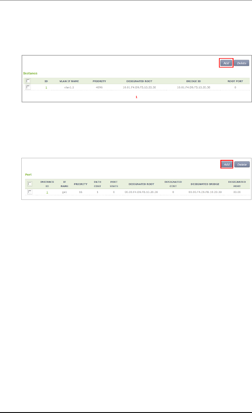
CHAPTER 3. Data Network Function
© SAMSUNG Electronics Co., Ltd. page 69 of 628
[Managing the MSTP VLAN instance]
When you select the <Instance> menu, the configured MSTP VLAN Instance list is
displayed on the window. Click the <Add> or <Delete> button to add or delete an instance.
Figure 31. Spanning Tree Configuration Window (2)
[Managing MSTP Port]
When you select the <Port> menu, the configured MSTP Port list is displayed on the
window. Click the <Add> or <Delete> button to add or delete a port.
Figure 32. Spanning Tree Configuration Window (3)

CHAPTER 3. Data Network Function
© SAMSUNG Electronics Co., Ltd. page 70 of 628
3.4 Layer 3 Protocol Configuration
This provides the IP address configuration and static/dynamic routing configuration of an
interface. The APC provides the Open Shortest Path First (OSPF) routing protocol.
3.4.1 IP Address Configuration
The procedure for IP address configuration is given below.
1) Go to configure interface configuration mode of CLI.
WEC8500# configure terminal
WEC8500/configure# interface ge2
2) Set up an IP address.
WEC8500/configure/interface ge2# ip address 100.100.100.1/24
3) Enable the interface.
WEC8500/configure/interface ge2# no shutdown
3.4.2 Static Routing Configuration
Configuration using CLI
1) Go to configure mode of CLI.
WEC8500# configure terminal
2) Configure static routing.
WEC8500/configure# ip route 10.2.3.0/24 30.30.30.2
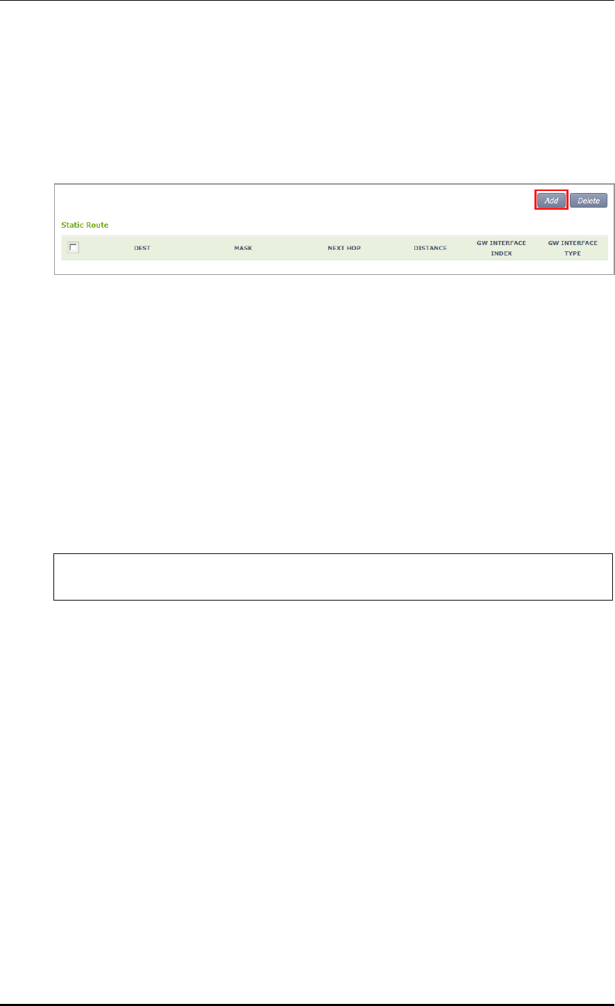
CHAPTER 3. Data Network Function
© SAMSUNG Electronics Co., Ltd. page 71 of 628
Configuration using Web UI
In the menu bar of <WEC Main window>, select <Configuration> and then select the
<Controller> <Network> <Static Route> menu in the sub-menus.
The configured static route list is displayed on the window. When you click the <Add> or
<Delete> button, you can add or delete a static routing entry.
Figure 33. Static Routing Configuration Window
After adding or deleting an entry, check if the information is reflected to the list in the
Static Route window. If the added information is not displayed, it means the added routing
information is not enabled. If the operational status of an interface that will be used as a
routing result is not UP, check the interface status through CLI or Web UI.
Because only enabled routing entries are listed in the Web UI, you cannot remove a
disabled routing entry.
3.4.3 IP Multicast Routing Configuration
1) Go to configure mode of CLI.
WEC8500# configure terminal
WEC8500/configure#
2) Enable or disable multicast-routing.
ip multicast-routing
no multicast-routing
3) Check multicast-routing using the ‘show running-config network’ command.

CHAPTER 3. Data Network Function
© SAMSUNG Electronics Co., Ltd. page 72 of 628
3.4.4 PIM Configuration
The procedure for Protocol Independent Multicast (PIM) configuration is given below.
1) Go to configure interface configuration mode of CLI.
WEC8500# configure terminal
WEC8500/configure# interface ge2
2) Configure the PIM sparse mode to an interface.
WEC8500/configure/interface ge2# ip pim sparse-mode
3) Check a configured PIM using the ‘show running-config network’ command.
To check the multicast-routing table, use the ‘show ip mroute’ command.
WEC8500# show ip mroute
(90.90.1.242, 224.0.1.1) Iif: mgmt0 Oifs: pimreg
3.4.5 OSPF Configuration
3.4.5.1 General settings
Configuration using CLI
1) Go to configure ospf configuration mode of CLI.
WEC8500# configure terminal
WEC8500/configure# router ospf
WEC8500/configure# router ospf ?
1 - 10 OSPF process ID
2) Configure the process ID from 1 to 10.
WEC8500/configure# router ospf ?
1 - 10 OSPF process ID
WEC8500/configure# router ospf 2
WEC8500/configure/router/ospf 2#
Parameter
Description
OSPF process ID
Configure the process ID from 1 to 10.
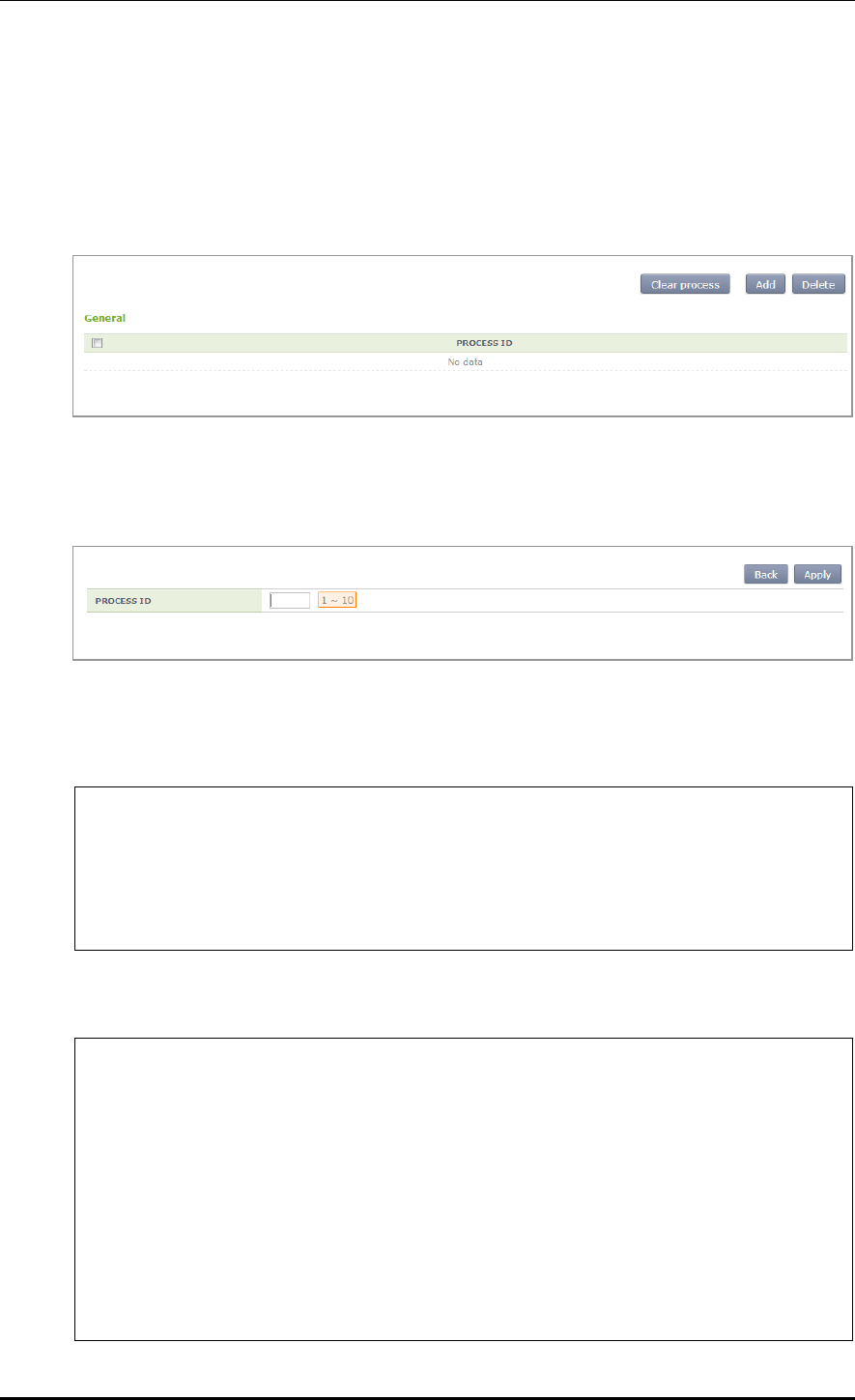
CHAPTER 3. Data Network Function
© SAMSUNG Electronics Co., Ltd. page 73 of 628
Configuration using Web UI
In the menu bar of <WEC Main window>, select <Configuration> and then select the
<Controller> <Network> <OSPF> <General> menu in the sub-menus.
The OSPF initial window is shown below.
Figure 34. OSPF Configuration Window
Click the <Add> button and configure the PROCESS ID to 1-10 in the below screen.
Configuration using CLI
1) Go to configure ospf configuration mode of CLI.
WEC8500# configure terminal
WEC8500/configure# router ospf
WEC8500/configure# router ospf ?
1 - 10 OSPF process ID
WEC8500/configure# router ospf 2
WEC8500/configure/router/ospf 2#
2) The detail configuration items of a process ID are as follows:
WEC8500/configure/router/ospf 2# ?
area OSPF area parameters
auto-cost Calculate OSPF interface cost according
to bandwidth
capability Enable specific OSPF feature
compatible OSPF compatibility list
default-information Control distribution of default
information
default-metric Set metric of redistributed routes
distance Define an administrative distance
distribute-list Filter networks in routing updates

CHAPTER 3. Data Network Function
© SAMSUNG Electronics Co., Ltd. page 74 of 628
exit Exit from router mode
host OSPF stub host entry
max-concurrent-dd Maximum number allowed to process DD
concurrently
maximum-area Maximum number of ospf area
neighbor Specify a neighbor router
network Enable routing on an IP network
ospf OSPF specific commands
overflow Control overflow
passive-interface Suppress routing updates on an interface
redistribute Redistribute information from another
routing protocol
router-id Router-id for the OSPF process
summary-address Configure IP address summaries
timers Adjust routing timers
3) Router ID configuration
Enter an IP address to use.
WEC8500/configure/router/ospf 2# router-id ?
A.B.C.D OSPF router-id in IP address format
WEC8500/configure/router/ospf 2# router-id 10.10.0.1 ?
<cr>
Parameter
Description
OSPF router-id in IP address
Enter an IP address.
4) AUTO COST configuration
Enter an OSPF cost value (1-4294967) to use.
WEC8500/configure/router/ospf 2# auto-cost ?
reference-bandwidth Use reference bandwidth method to assign
OSPF cost
WEC8500/configure/router/ospf 2# auto-cost reference-bandwidth ?
1 - 4294967 The reference bandwidth in terms of
Mbits per second
WEC8500/configure/router/ospf 2# auto-cost reference-bandwidth 200 ?
<cr>
WEC8500/configure/router/ospf 2# auto-cost reference-bandwidth 200
Parameter
Description
reference-bandwidth
Enter a value from 1-4294967.

CHAPTER 3. Data Network Function
© SAMSUNG Electronics Co., Ltd. page 75 of 628
5) CAPABILITY OPAQUE configuration
Enter the capability opaque.
WEC8500/configure/router/ospf 2# capability ?
opaque Opaque LSA
WEC8500/configure/router/ospf 2# capability opaque ?
<cr>
WEC8500/configure/router/ospf 2# capability opaque
Parameter
Description
Capability opaque
Enabled when the CLI is entered.
6) COMPATIBLE RFC configuration
Enter the compatible rfc1583.
WEC8500/configure/router/ospf 2# compatible ?
rfc1583 Compatible with RFC 1583
WEC8500/configure/router/ospf 2# compatible rfc1583 ?
<cr>
WEC8500/configure/router/ospf 2# compatible rfc1583
Parameter
Description
compatible rfc1583
Enabled when the CLI is entered.
7) DEFAULT METRIC configuration
Enter the DEFAULT METRIC (1-16777214) to use.
WEC8500/configure/router/ospf 2# default-metric ?
1 - 16777214 Default metric
WEC8500/configure/router/ospf 2# default-metric 3 ?
<cr>
WEC8500/configure/router/ospf 2# default-metric 3
Parameter
Description
Default metric
Enter a value from 1-16777214.
8) MAX CONCURRENT DD configuration
Enter the MAX CONCURRENT DD (1-65535) to use.
WEC8500/configure/router/ospf 2# max-concurrent-dd ?
1 - 65535 Number of DD process
WEC8500/configure/router/ospf 2# max-concurrent-dd 2 ?
<cr>
WEC8500/configure/router/ospf 2# max-concurrent-dd 2

CHAPTER 3. Data Network Function
© SAMSUNG Electronics Co., Ltd. page 76 of 628
9) MAXIMUM AREA configuration
Enter the DEFAULT METRIC (1-4294967294) to use.
WEC8500/configure/router/ospf 2# maximum-area ?
1 - 4294967294 Area limit
WEC8500/configure/router/ospf 2# maximum-area 3 ?
<cr>
WEC8500/configure/router/ospf 2# maximum-area 3
10) SPF TIMER (MILLISECONDS) configuration
Configure the SPF TIMER (MILLISECONDS) value.
WEC8500/configure/router/ospf 2# timers ?
spf OSPF SPF timers
WEC8500/configure/router/ospf 2# timers spf ?
exp Use exponential backoff delays
WEC8500/configure/router/ospf 2# timers spf exp ?
0 - 2147483647 Minimum Delay between receiving a change
to SPF calculation in
milliseconds
WEC8500/configure/router/ospf 2# timers spf exp 3 ?
0 - 2147483647 Maximum Delay between receiving a change
to SPF calculation in
milliseconds
WEC8500/configure/router/ospf 2# timers spf exp 3 100 ?
<cr>
WEC8500/configure/router/ospf 2# timers spf exp 3 100
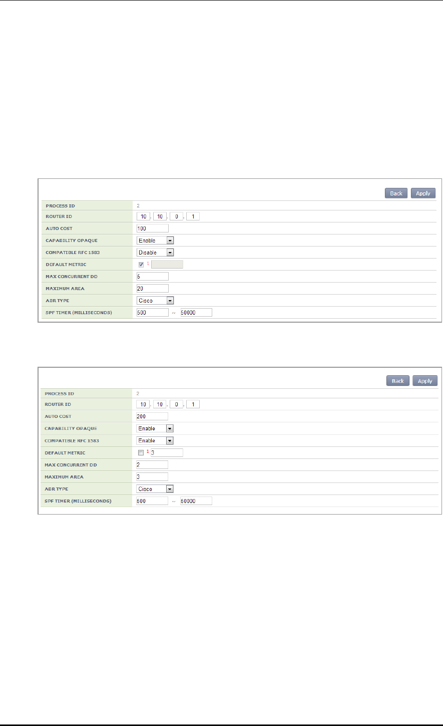
CHAPTER 3. Data Network Function
© SAMSUNG Electronics Co., Ltd. page 77 of 628
Configuration using Web UI
In the menu bar of <WEC Main window>, select <Configuration> and then select the
<Controller> <Network> <OSPF> <General> menu in the sub-menus.
Click a PROCESS ID that user wants to configure. The OSPF configuration window is
shown below.
Use the value configured in ‘Configuration using CLI’ as a user-defined value in the below
screen.
The value configured in ‘Configuration using CLI’ is shown in the below screen.

CHAPTER 3. Data Network Function
© SAMSUNG Electronics Co., Ltd. page 78 of 628
3.4.5.2 Default Information Configuration of General Settings
Configuration using CLI
1) Detail configuration of OSPF default-information
WEC8500/configure/router/ospf 2# default-information ?
originate Distribute a default route
WEC8500/configure/router/ospf 2# default-information originate ?
always Always advertise default route
metric OSPF default metric
metric-type OSPF metric type for default routes
route-map Route map reference
<cr>
2) Configuration of default-information ALWAYS
WEC8500/configure/router/ospf 2# default-information originate ?
always Always advertise default route
metric OSPF default metric
metric-type OSPF metric type for default routes
route-map Route map reference
<cr>
WEC8500/configure/router/ospf 2# default-information originate
always ?
<cr>
WEC8500/configure/router/ospf 2# default-information originate always
WEC8500/configure/router/ospf 2#
3) Configuration of default-information METRIC
Configure the OSPF metric (0-16777214) value.
WEC8500/configure/router/ospf 2# default-information originate
metric ?
0 - 16777214 OSPF metric
WEC8500/configure/router/ospf 2# default-information originate metric
3 ?
<cr>
WEC8500/configure/router/ospf 2# default-information originate metric
3
WEC8500/configure/router/ospf 2#
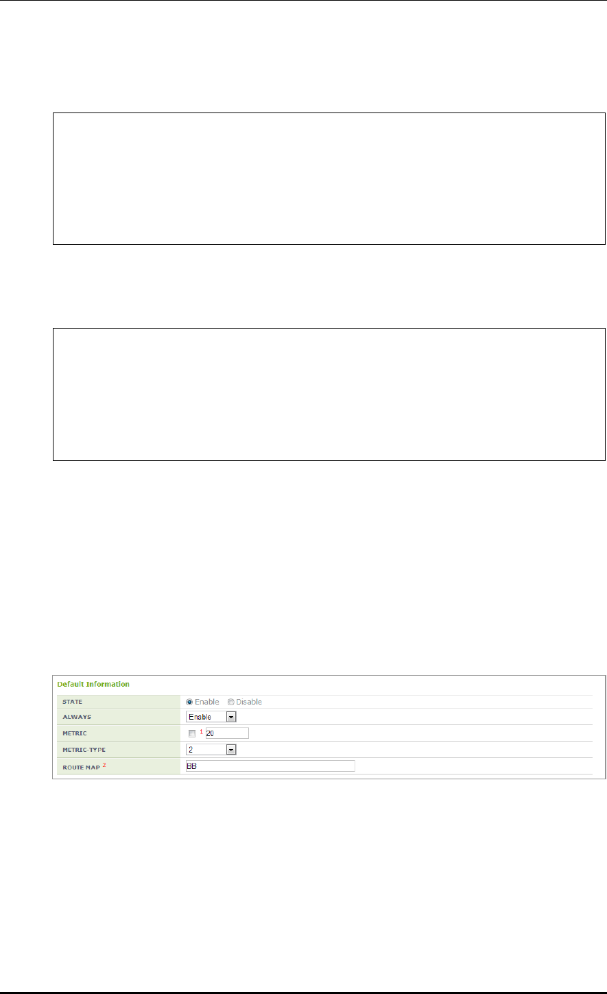
CHAPTER 3. Data Network Function
© SAMSUNG Electronics Co., Ltd. page 79 of 628
4) Configuration of default-information METRIC-TYPE
Configure the OSPF metric-type (1/2) value.
WEC8500/configure/router/ospf 2# default-information originate metric-
type ?
1 Set OSPF External Type 1 metrics
2 Set OSPF External Type 2 metrics
WEC8500/configure/router/ospf 2# default-information originate metric-
type 1 ?
<cr>
5) Configuration of default-information ROUTE MAP
Enter the name of pointer to route-map entries.
WEC8500/configure/router/ospf 2# default-information originate route-
map ?
<WORD> Pointer to route-map entries
WEC8500/configure/router/ospf 2# default-information originate route-
map AA
WEC8500/configure/router/ospf 2#
Configuration using Web UI
In the menu bar of <WEC Main window>, select <Configuration> and then select the
<Controller> <Network> <OSPF> <General> menu in the sub-menus.
Click a PROCESS ID that user wants to configure. The OSPF configuration window is
shown below.
Use the value configured in ‘Configuration using CLI’ as a user-defined value in the below
screen.

CHAPTER 3. Data Network Function
© SAMSUNG Electronics Co., Ltd. page 80 of 628
3.4.5.3 Distance Configuration of General Settings
Configuration using CLI
1) Detail configuration of OSPF distance
WEC8500/configure/router/ospf 2# distance ?
admin OSPF Administrative distance
ospf OSPF Distance
2) Distance admin configuration
Enter the OSPF Admin distance value.
WEC8500/configure/router/ospf 2# distance ?
admin OSPF Administrative distance
ospf OSPF Distance
WEC8500/configure/router/ospf 2# distance admin ?
1 - 255 OSPF Administrative distance
WEC8500/configure/router/ospf 2# distance admin 100
The OSPF Admin distance is displayed as GENERAL in the Web UI.
3) Configuration of EXTERNAL distance ospf
Enter the OSPF EXTERNAL distance value.
WEC8500/configure/router/ospf 2# distance ospf ?
external External routes
inter-area Inter-area routes
intra-area Intra-area routes
WEC8500/configure/router/ospf 2# distance ospf external ?
1 - 255 <1-255> Distance for external/inter-
area/intra-area routes
WEC8500/configure/router/ospf 2# distance ospf external 50
WEC8500/configure/router/ospf 2#

CHAPTER 3. Data Network Function
© SAMSUNG Electronics Co., Ltd. page 81 of 628
4) Configuration of INTER-AREA distance ospf
Enter the OSPF INTER-AREA distance value.
WEC8500/configure/router/ospf 2# distance ospf inter-area ?
1 - 255 <1-255> Distance for external/inter-
area/intra-area routes
WEC8500/configure/router/ospf 2# distance ospf inter-area 50 ?
<cr>
WEC8500/configure/router/ospf 2# distance ospf inter-area 50
WEC8500/configure/router/ospf 2#
5) Configuration of INTRA-AREA distance ospf
Enter the OSPF INTRA-AREA distance value.
WEC8500/configure/router/ospf 2# distance ospf intra-area ?
1 - 255 <1-255> Distance for external/inter-
area/intra-area routes
WEC8500/configure/router/ospf 2# distance ospf intra-area 50 ?
<cr>
WEC8500/configure/router/ospf 2# distance ospf intra-area 50
WEC8500/configure/router/ospf 2#
Configuration using Web UI
In the menu bar of <WEC Main window>, select <Configuration> and then select the
<Controller> <Network> <OSPF> <General> menu in the sub-menus.
Click a PROCESS ID that user wants to configure. The OSPF configuration window is
shown below.
Use the value configured in ‘Configuration using CLI’ as a user-defined value in the below
screen.

CHAPTER 3. Data Network Function
© SAMSUNG Electronics Co., Ltd. page 82 of 628
3.4.5.4 Overflow Configuration of General Settings
Configuration using CLI
1) Detail configuration of OSPF overflow
WEC8500/configure/router/ospf 2# overflow ?
database Database
WEC8500/configure/router/ospf 2# overflow database ?
external External link states
0 - 4294967294 Maximum number of LSAs
WEC8500/configure/router/ospf 2# overflow database
2) Overflow external configuration
Enter the maximum number of LSAs and time to recover (0 not recover) value.
WEC8500/configure/router/ospf 2# overflow ?
database Database
WEC8500/configure/router/ospf 2# overflow database ?
external External link states
0 - 4294967294 Maximum number of LSAs
WEC8500/configure/router/ospf 2# overflow database external ?
0 - 2147483647 Maximum number of LSAs
WEC8500/configure/router/ospf 2# overflow database external 3 ?
0 - 65535 Time to recover (0 not recover)
WEC8500/configure/router/ospf 2# overflow database external 3 10 ?
<cr>
WEC8500/configure/router/ospf 2# overflow database external 3 10
3) Configuration of maximum number of LSAs
Enter the maximum number of LSAs and hard limit value.
WEC8500/configure/router/ospf 2# overflow ?
database Database
WEC8500/configure/router/ospf 2# overflow database ?
external External link states
0 - 4294967294 Maximum number of LSAs

CHAPTER 3. Data Network Function
© SAMSUNG Electronics Co., Ltd. page 83 of 628
WEC8500/configure/router/ospf 2# overflow database 100 ?
hard Hard limit; Instance will be shutdown if
exceed
soft Soft limit; Warning will be given if
exceed
<cr>
WEC8500/configure/router/ospf 2# overflow database 100 hard ?
<cr>
WEC8500/configure/router/ospf 2# overflow database 100 hard
Enter the maximum number of LSAs and soft limit value.
WEC8500/configure/router/ospf 2# overflow ?
database Database
WEC8500/configure/router/ospf 2# overflow database ?
external External link states
0 - 4294967294 Maximum number of LSAs
WEC8500/configure/router/ospf 2# overflow database 100 ?
hard Hard limit; Instance will be shutdown if
exceed
soft Soft limit; Warning will be given if
exceed
<cr>
WEC8500/configure/router/ospf 2# overflow database 100 soft ?
<cr>
WEC8500/configure/router/ospf 2# overflow database 100 soft
Configuration using Web UI
In the menu bar of <WEC Main window>, select <Configuration> and then select the
<Controller> <Network> <OSPF> <General> menu in the sub-menus.
Click a PROCESS ID that user wants to configure. The OSPF configuration window is
shown below.
Use the value configured in ‘Configuration using CLI’ as a user-defined value in the below
screen.

CHAPTER 3. Data Network Function
© SAMSUNG Electronics Co., Ltd. page 84 of 628
3.4.5.5 Network Configuration
Configuration using CLI
Go to configure ospf configuration mode of CLI.
WEC8500/configure/router/ospf 2# ?
area OSPF area parameters
auto-cost Calculate OSPF interface cost according
to bandwidth
capability Enable specific OSPF feature
compatible OSPF compatibility list
default-information Control distribution of default
information
default-metric Set metric of redistributed routes
distance Define an administrative distance
distribute-list Filter networks in routing updates
exit Exit from router mode
host OSPF stub host entry
max-concurrent-dd Maximum number allowed to process DD
concurrently
maximum-area Maximum number of ospf area
neighbor Specify a neighbor router
network Enable routing on an IP network
ospf OSPF specific commands
overflow Control overflow
passive-interface Suppress routing updates on an interface
redistribute Redistribute information from another
routing protocol
router-id Router-id for the OSPF process
summary-address Configure IP address summaries
timers Adjust routing timers
WEC8500/configure/router/ospf 2# network ?
A.B.C.D Network number
A.B.C.D/M OSPF network prefix
Configuration using Web UI
In the menu bar of <WEC Main window>, select <Configuration> and then select the
<Controller> <Network> <OSPF> <Network> menu in the sub-menus.
The OSPF initial window is shown below.

CHAPTER 3. Data Network Function
© SAMSUNG Electronics Co., Ltd. page 85 of 628
3.4.5.6 Configuration of Network Details
Configuration using CLI
1) Go to configure ospf configuration mode of CLI.
WEC8500# configure terminal
WEC8500/configure# router ospf
WEC8500/configure# router ospf ?
1 - 10 OSPF process ID
2) Network configuration
Configure the ADDRESS, NETMASK, and AREA ID of a user-defined network.
WEC8500/configure/router/ospf 2# network ?
A.B.C.D Network number
A.B.C.D/M OSPF network prefix
WEC8500/configure/router/ospf 2# network 100.100.100.1 ?
A.B.C.D OSPF wild card bits(network mask)
WEC8500/configure/router/ospf 2# network 100.100.100.1 255.255.255.0 ?
area Set the OSPF area ID
WEC8500/configure/router/ospf 2# network 100.100.100.1 255.255.255.0 ?
area Set the OSPF area ID
WEC8500/configure/router/ospf 2# network 100.100.100.1 255.255.255.0
area ?
0 - 4294967295 OSPF area ID as a decimal value
A.B.C.D OSPF area ID in IP address format
WEC8500/configure/router/ospf 2# network 100.100.100.1 255.255.255.0
area 3 ?
<cr>
WEC8500/configure/router/ospf 2# network 100.100.100.1 255.255.255.0
area 3
Parameter
Description
NETWORK ADDRESS
Network number OSPF network prefix
NETMASK
OSPF wild card bits (network mask)
AREA ID
OSPF area ID as a decimal value/ OSPF area ID in IP address format

CHAPTER 3. Data Network Function
© SAMSUNG Electronics Co., Ltd. page 86 of 628
Configuration using Web UI
In the menu bar of <WEC Main window>, select <Configuration> and then select the
<Controller> <Network> <OSPF> <Network> menu in the sub-menus.
Enter the NETWORK ADDRESS, NETMASK, and AREA ID and click the
<Apply> button.
3.4.5.7 Redistribute Configuration
Configuration using CLI
Go to configure ospf configuration mode of CLI.
WEC8500/configure/router/ospf 2# ?
area OSPF area parameters
auto-cost Calculate OSPF interface cost according
to bandwidth
capability Enable specific OSPF feature
compatible OSPF compatibility list
default-information Control distribution of default
information
default-metric Set metric of redistributed routes
distance Define an administrative distance
distribute-list Filter networks in routing updates
exit Exit from router mode
host OSPF stub host entry
max-concurrent-dd Maximum number allowed to process DD
concurrently
maximum-area Maximum number of ospf area
neighbor Specify a neighbor router
network Enable routing on an IP network
ospf OSPF specific commands
overflow Control overflow
passive-interface Suppress routing updates on an interface
redistribute Redistribute information from another
routing protocol
router-id Router-id for the OSPF process
summary-address Configure IP address summaries
timers Adjust routing timers
WEC8500/configure/router/ospf 2# redistribute ?
connected Connected
static Static routes
ospf Open Shortest Path First (OSPF)
WEC8500/configure/router/ospf 2# redistribute

CHAPTER 3. Data Network Function
© SAMSUNG Electronics Co., Ltd. page 87 of 628
Configuration using Web UI
In the menu bar of <WEC Main window>, select <Configuration> and then select the
<Controller> <Network> <OSPF> <Redistribute> menu in the sub-menus.
The OSPF Redistribute initial window is shown below.
Configuration using CLI
1) Connected configuration
The metric, metric-type, route-map, tag detail setting and default setting can be
configured.
WEC8500/configure/router/ospf 2# redistribute ?
connected Connected
static Static routes
ospf Open Shortest Path First (OSPF)
WEC8500/configure/router/ospf 2# redistribute connected ?
metric OSPF default metric
metric-type OSPF metric type for default routes
route-map Route map reference
tag Set tag for routes redistributed into
OSPF
2) Metric configuration
WEC8500/configure/router/ospf 2# redistribute connected ?
metric OSPF default metric
metric-type OSPF metric type for default routes
route-map Route map reference
tag Set tag for routes redistributed into
OSPF
<cr>
WEC8500/configure/router/ospf 2# redistribute connected metric ?
1 - 16777214 OSPF metric
WEC8500/configure/router/ospf 2# redistribute connected metric 3 ?
<cr>
WEC8500/configure/router/ospf 2# redistribute connected metric 3

CHAPTER 3. Data Network Function
© SAMSUNG Electronics Co., Ltd. page 88 of 628
Parameter
Description
metric
Enter a value from 1-16777214.
3) Metric-type configuration
WEC8500/configure/router/ospf 2# redistribute connected metric-type ?
1 Set OSPF External Type 1 metrics
2 Set OSPF External Type 2 metrics
WEC8500/configure/router/ospf 2# redistribute connected metric-type
1 ?
<cr>
WEC8500/configure/router/ospf 2# redistribute connected metric-type 1
Parameter
Description
metric-type
Select 1 or 2.
4) Route-map configuration
WEC8500/configure/router/ospf 2# redistribute connected route-map ?
<WORD> Pointer to route-map entries
WEC8500/configure/router/ospf 2# redistribute connected route-map a ?
<cr>
WEC8500/configure/router/ospf 2# redistribute connected route-map a
Parameter
Description
route-map entries
Enter <WORD>.
5) Tag configuration
WEC8500/configure/router/ospf 2# redistribute connected tag ?
0 - 4294967295 32-bit tag value
WEC8500/configure/router/ospf 2# redistribute connected tag 3 ?
<cr>
WEC8500/configure/router/ospf 2# redistribute connected tag 3
Parameter
Description
Tag value
Enter a tag value from 0-4294967295.
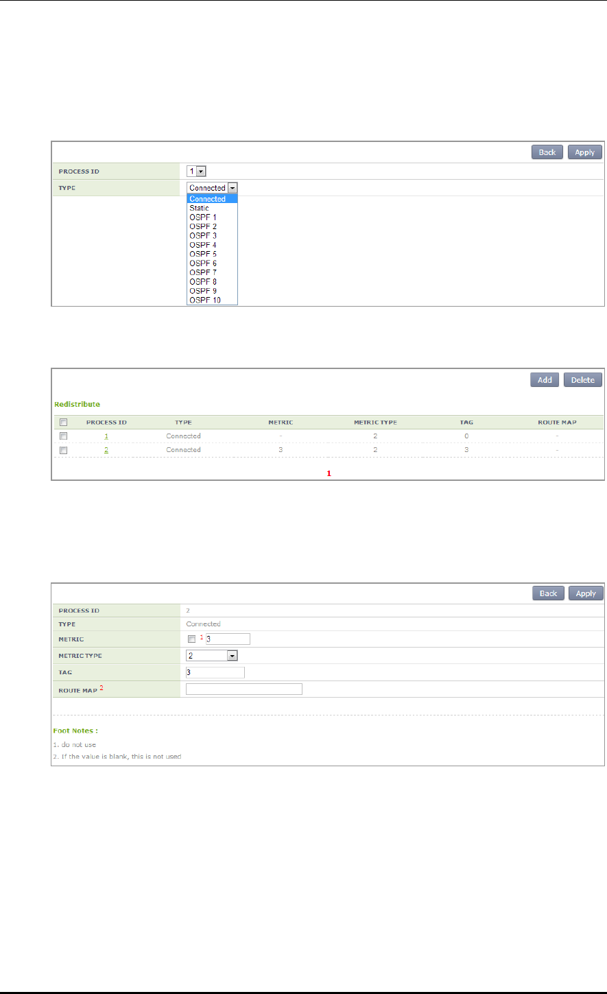
CHAPTER 3. Data Network Function
© SAMSUNG Electronics Co., Ltd. page 89 of 628
Configuration using Web UI
In the menu bar of <WEC Main window>, select <Configuration> and then select the
<Controller> <Network> <OSPF> <Redistribute> menu in the sub-menus.
After configuring Redistribute default, select a PROCESS ID for detail configuration.
Configuring Redistribute details
Configure the details of metric, metric-type, route-map, or tag, etc. which is configured in
CLI.
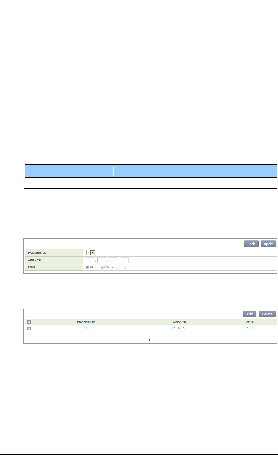
CHAPTER 3. Data Network Function
© SAMSUNG Electronics Co., Ltd. page 90 of 628
3.4.5.8 AREA Configuration
The Area configuration includes Stub, Not So Stubby Areas (NSSA), Virtual-Link, Range,
or Detail.
1) Stub configuration
Configuration using CLI
WEC8500/configure/router/ospf 2# area 1 stub ?
no-summary Do not inject inter-area routes into
stub
<cr>
WEC8500/configure/router/ospf 2# area 1 stub no-summary ?
<cr>
WEC8500/configure/router/ospf 2# area 1 stub no-summary
Parameter
Description
no-summary
Select Stub or No Summary.
Configuration using Web UI
In the menu bar of <WEC Main window>, select <Configuration> and then select the
<Controller> <Network> <OSPF> <Area> <Stub> menu in the sub-menus.
In the Stub add page, configure the details and click the <Apply> button. Then, the initial
window is changed as shown below.

CHAPTER 3. Data Network Function
© SAMSUNG Electronics Co., Ltd. page 91 of 628
2) NSSA configuration
Configuration using CLI
WEC8500/configure/router/ospf 2# area 1 nssa ?
default-information-originate Originate Type 7 default into NSSA
area
no-redistribution No redistribution into this NSSA area
no-summary Do not send summary LSA into NSSA
translator-role NSSA-ABR Translator role
<cr>
default-information-originate configuration CLI of NSSA
The metric, metric-type, no-redistribution, no-summary, or translator-role details can be
configured.
WEC8500/configure/router/ospf 1# area 2 nssa default-information-
originate ?
metric OSPF default metric
metric-type OSPF metric type for default routes
no-redistribution No redistribution into this NSSA area
no-summary Do not send summary LSA into NSSA
translator-role NSSA-ABR Translator role
<cr>
Metric configuration of NSSA default-information-originate
WEC8500/configure/router/ospf 1# area 2 nssa default-information-
originate metric ?
0 - 16777214 OSPF metric
WEC8500/configure/router/ospf 1# area 2 nssa default-information-
originate metric 3
WEC8500/configure/router/ospf 1#
Parameter
Description
OSPF metric
Enter a value from 0-16777214.

CHAPTER 3. Data Network Function
© SAMSUNG Electronics Co., Ltd. page 92 of 628
Metric-type configuration of NSSA default-information-originate
WEC8500/configure/router/ospf 1# area 2 nssa default-information-
originate metric-type ?
1 - 2 OSPF Link State type
WEC8500/configure/router/ospf 1# area 2 nssa default-information-
originate metric-type 2
WEC8500/configure/router/ospf 1#
Parameter
Description
OSPF metric-type
Select 1 or 2.
Configuring no-redistribution of NSSA default-information-originate
WEC8500/configure/router/ospf 1# area 2 nssa default-information-
originate ?
metric OSPF default metric
metric-type OSPF metric type for default routes
no-redistribution No redistribution into this NSSA area
no-summary Do not send summary LSA into NSSA
translator-role NSSA-ABR Translator role
<cr>
WEC8500/configure/router/ospf 1# area 2 nssa default-information-
originate no-redistribution ?
<cr>
WEC8500/configure/router/ospf 1# area 2 nssa default-information-
originate no-redistribution
Parameter
Description
no-redistribution
Enable/Disable Configuration
Configuring no-summary NSSA default-information-originate
WEC8500/configure/router/ospf 1# area 2 nssa default-information-
originate no-summary ?
<cr>
WEC8500/configure/router/ospf 1# area 2 nssa default-information-
originate no-summary
WEC8500/configure/router/ospf 1#
Parameter
Description
no-summary
Enable/Disable Configuration

CHAPTER 3. Data Network Function
© SAMSUNG Electronics Co., Ltd. page 93 of 628
Configuring translator-role of NSSA default-information-originate
WEC8500/configure/router/ospf 1# area 2 nssa default-information-
originate translator-role ?
always Translate always
candidate Candidate for translator (default)
never Do not translate
WEC8500/configure/router/ospf 1# area 2 nssa default-information-
originate translator-role always ?
no-redistribution No redistribution into this NSSA area
no-summary Do not send summary LSA into NSSA
<cr>
WEC8500/configure/router/ospf 1# area 2 nssa default-information-
originate translator-role candidate ?
no-redistribution No redistribution into this NSSA area
no-summary Do not send summary LSA into NSSA
<cr>
WEC8500/configure/router/ospf 1# area 2 nssa default-information-
originate translator-role never ?
no-redistribution No redistribution into this NSSA area
no-summary Do not send summary LSA into NSSA
<cr>
WEC8500/configure/router/ospf 1# area 2 nssa default-information-
originate translator-role never
Parameter
Description
always
Translate always
candidate
Candidate for translator (default)
never
Do not translate
After the configuration of each parameter is finished, enable or disable the no-
redistribution or no-summary parameter.
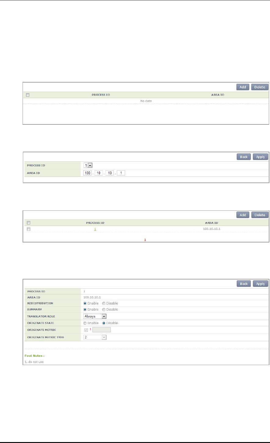
CHAPTER 3. Data Network Function
© SAMSUNG Electronics Co., Ltd. page 94 of 628
Configuration using Web UI
In the menu bar of <WEC Main window>, select <Configuration> and then select the
<Controller> <Network> <OSPF> <Area> <NSSA> menu in the sub-menus.
The default window is shown below.
The default configuration screen is shown below.
The NSSA window screen is shown as below after detail configuration is completed.
If you select a Process ID after NSSA default configuration, operator can do detail
configuration.

CHAPTER 3. Data Network Function
© SAMSUNG Electronics Co., Ltd. page 95 of 628
3) Virtual-Link configuration
Configuration using CLI
WEC8500/configure/router/ospf 1# area 2 ?
authentication Enable authentication
default-cost Set the summary-default cost of a NSSA
or stub area
filter-list Filter networks between OSPF areas
nssa Specify a NSSA area
range Summarize routes matching address/mask
(border routers only)
shortcut Configure the area's shortcutting mode
stub Configure OSPF area as stub
virtual-link Define a virtual link and its parameters
WEC8500/configure/router/ospf 1# area 2 virtual-link ?
A.B.C.D ID (IP addr) associated with virtual
link neighbor
WEC8500/configure/router/ospf 1# area 2 virtual-link 10.10.10.1 ?
authentication Enable authentication
authentication-key Set authentication key
dead-interval Dead router detection time
hello-interval Hello packet interval
message-digest-key Set message digest key
retransmit-interval LSA retransmit interval
transmit-delay LSA transmission delay
<cr>
To configure the Virtual-Link, enter an ID (router ID of OSPF that is connected via Virtual)
and configure the detail items. The detail items include authentication, authentication-key,
dead-interval, hello-interval, message-digest-key, retransmit-interval, or transmit-delay, etc.
Authentication configuration
Operator can configure authentication and message-digest.
WEC8500/configure/router/ospf 2# area 2 virtual-link 10.10.10.1
authentication ?
message-digest Use message-digest authentication
<cr>
WEC8500/configure/router/ospf 2# area 2 virtual-link 10.10.10.1
authentication message-digest ?
<cr>
WEC8500/configure/router/ospf 2# area 2 virtual-link 10.10.10.1
authentication message-digest
Authentication-key configuration
Enter 8-character word to be used as an authentication key. Use the entered 8-character as
an authentication key.

CHAPTER 3. Data Network Function
© SAMSUNG Electronics Co., Ltd. page 96 of 628
WEC8500/configure/router/ospf 2# area 2 virtual-link 10.10.10.1
authentication-key ?
<WORD> Authentication key (8 chars)
WEC8500/configure/router/ospf 2# area 2 virtual-link 10.10.10.1
authentication-key aaaaaaaa
WEC8500/configure/router/ospf 2#
Dead-interval configuration
The default value of dead-interval is 4 times of hello-interval. Because the default hello-
interval is configured to 10 sec., the dead-interval will be 40 seconds if the hello-interval is
not configured. In addition, operator can change it to a value between 1 second and 65535
seconds.
WEC8500/configure/router/ospf 2# area 2 virtual-link 10.10.10.1 dead-
interval ?
1 - 65535 Seconds
WEC8500/configure/router/ospf 2# area 2 virtual-link 10.10.10.1 dead-
interval 50
WEC8500/configure/router/ospf 2#
Hello-interval configuration
The default hello-interval is 10 seconds. In addition, operator can change it to a value
between 1 second and 65535 seconds.
WEC8500/configure/router/ospf 2# area 2 virtual-link 10.10.10.1 hello-
interval ?
1 - 65535 Seconds
WEC8500/configure/router/ospf 2# area 2 virtual-link 10.10.10.1 hello-
interval 50
WEC8500/configure/router/ospf 2#
Message-digest-key configuration
The message-digest-key configures a key ID between 1 and 255. After key ID
configuration, configure the authentication key by using the md5 algorithm. Operator can
enter maximum 16 characters.
When you enter an authentication key, the message-digest-key configuration is completed.
WEC8500/configure/router/ospf 2# area 2 virtual-link 10.10.10.1
message-digest-key ?
1 - 255 Key ID
WEC8500/configure/router/ospf 2# area 2 virtual-link 10.10.10.1
message-digest-key 2 ?
md5 Use MD5 algorithm
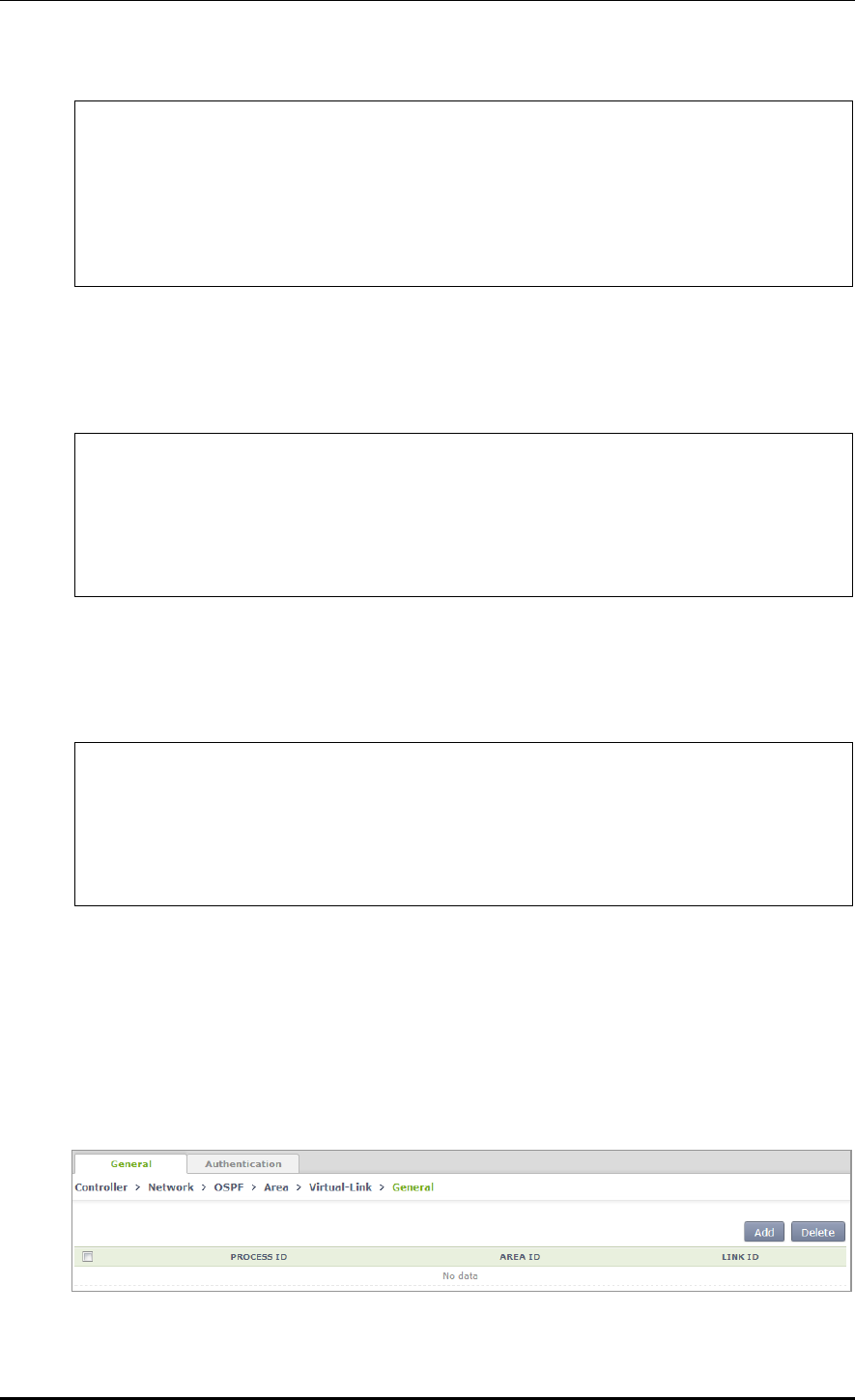
CHAPTER 3. Data Network Function
© SAMSUNG Electronics Co., Ltd. page 97 of 628
WEC8500/configure/router/ospf 2# area 2 virtual-link 10.10.10.1
message-digest-key 2 md5 ?
<WORD> Authentication key (16 chars)
WEC8500/configure/router/ospf 2# area 2 virtual-link 10.10.10.1
message-digest-key 2 md5 b
WEC8500/configure/router/ospf 2#
Retransmit-interval configuration
The default retransmit-interval is 5 seconds. In addition, operator can change it to a value
between 1 second and 65535 seconds.
WEC8500/configure/router/ospf 2# area 2 virtual-link 10.10.10.1
retransmit-interval ?
1 - 65535 Seconds (default: 5)
WEC8500/configure/router/ospf 2# area 2 virtual-link 10.10.10.1
retransmit-interval
Transmit-delay configuration
The default transmit-delay is 1 second. In addition, operator can change it to a value
between 1 second and 65535 seconds.
WEC8500/configure/router/ospf 2# area 2 virtual-link 10.10.10.1
transmit-delay ?
1 - 65535 Seconds
WEC8500/configure/router/ospf 2# area 2 virtual-link 10.10.10.1
transmit-delay 5
WEC8500/configure/router/ospf 2#
Configuration using Web UI
In the menu bar of <WEC Main window>, select <Configuration> and then select the
<Controller> <Network> <OSPF> <Area> <Virtual-Link> menu in the
sub-menus.
The default window is shown below.
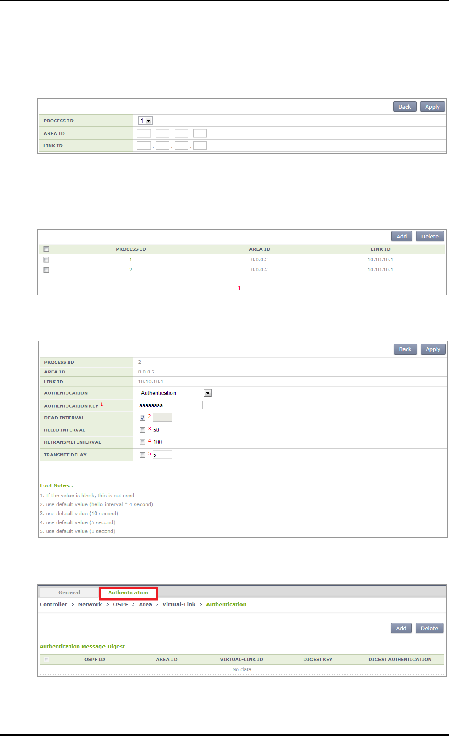
CHAPTER 3. Data Network Function
© SAMSUNG Electronics Co., Ltd. page 98 of 628
Unlike other configurations, there are two tabs at the top; General page and Authentication
page.
Start configuration in the General page for the basic configuration of Virtual-Link.
In the default configuration page, configure PROCESS ID, AREA ID, or LINK ID.
For detail configuration, select a PROCESS ID you want. Operator can do detail
configuration for an item you select.
The detail configuration page is shown below.
The Authentication page of a Virtual-Link is shown below.
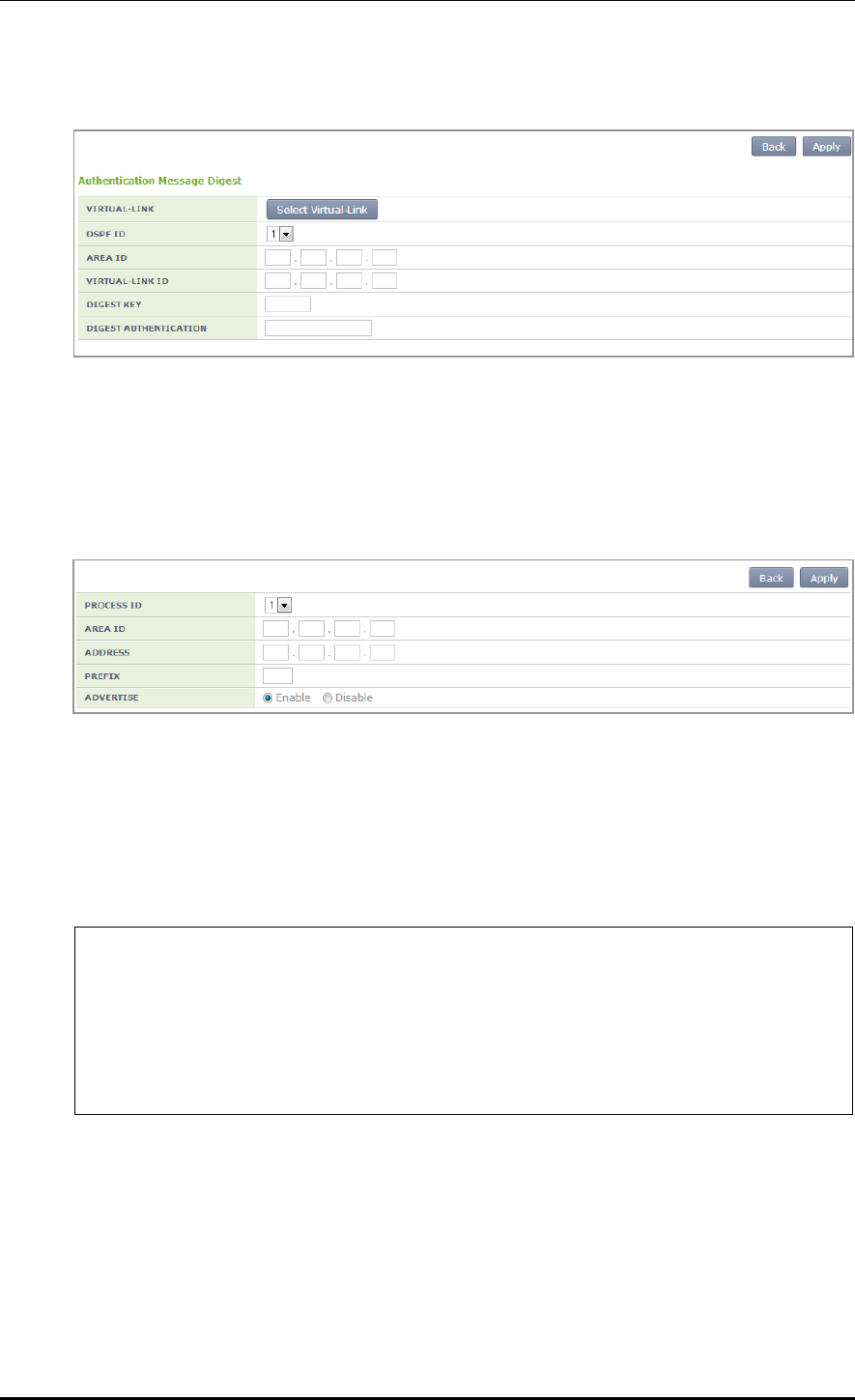
CHAPTER 3. Data Network Function
© SAMSUNG Electronics Co., Ltd. page 99 of 628
Click the <Select Virtual-Link> button.
Select a PROCESS ID that you have selected in the General page.
And then, configure Digest Key or Digest Authentication.
Just like CLI configuration, select a digest key between 1 and 255 and enter a key whose
length is 16-character or less for digest authentication.
4) Range configuration
Configuration using CLI
To configure the Range detail items, start detail configuration after entering an Area range
prefix value.
WEC8500/configure/router/ospf 2# area 2 range ?
A.B.C.D/M Area range prefix
WEC8500/configure/router/ospf 2# area 2 range 10.10.10.1/16 ?
advertise Advertise this range (default)
not-advertise DoNotAdvertise this range
<cr>
WEC8500/configure/router/ospf 2# area 2 range 10.10.10.1/16
The detail items include advertise or no-advertise configuration
Configure whether to advertise to the range or not.

CHAPTER 3. Data Network Function
© SAMSUNG Electronics Co., Ltd. page 100 of 628
Configuration using Web UI
In the menu bar of <WEC Main window>, select <Configuration> and then select the
<Controller> <Network> <OSPF> <Area> <Range> menu in the sub-menus.
The configuration page is as follows:
5) Detail configuration
Configuration using CLI
This is additional explanations for Area. Operator can configure authentication, default-cost,
or shortcut.
WEC8500/configure/router/ospf 2# area 2 ?
authentication Enable authentication
default-cost Set the summary-default cost of a NSSA
or stub area
filter-list Filter networks between OSPF areas
nssa Specify a NSSA area
range Summarize routes matching address/mask
(border routers only)
shortcut Configure the area's shortcutting mode
stub Configure OSPF area as stub
virtual-link Define a virtual link and its parameters
Authentication configuration
Operator can select whether to use authentication or message-digest function.
WEC8500/configure/router/ospf 2# area 2 authentication ?
message-digest Use message-digest authentication
<cr>
WEC8500/configure/router/ospf 2# area 2 authentication message-
digest ?
<cr>
WEC8500/configure/router/ospf 2# area 2 authentication message-digest
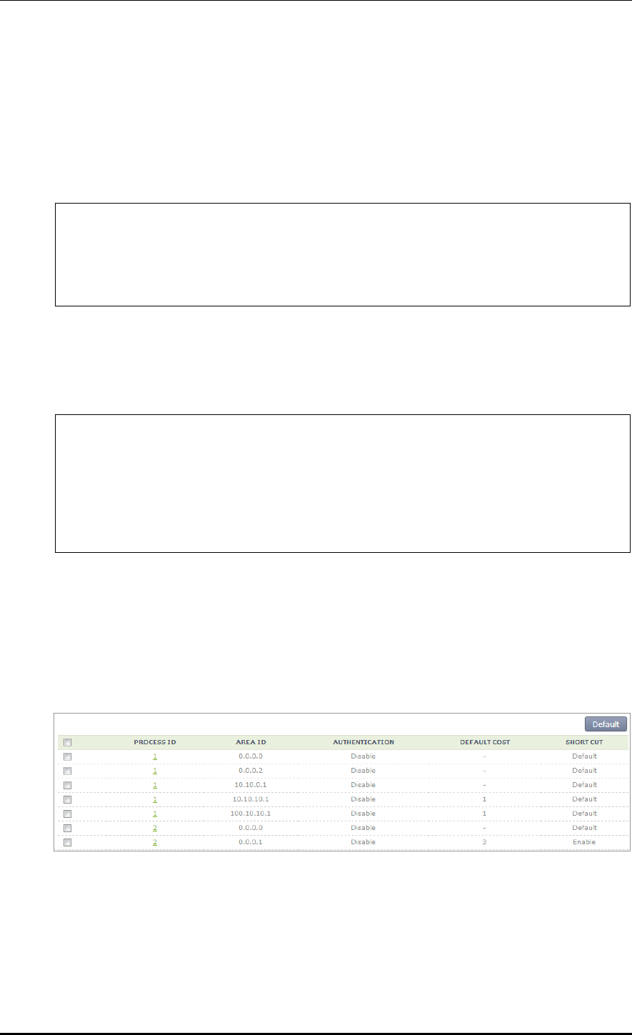
CHAPTER 3. Data Network Function
© SAMSUNG Electronics Co., Ltd. page 101 of 628
Default-cost configuration
Configure a value between 0 and 1677215 as a default-cost. However, operator can
configure the default-cost value in AREA ID whether a stub or NSSA is configured.
If you try to configure the default-cost in an ID where neither the two items are configured,
the following error phrase is displayed.
‘% The area is neither stub, nor NSSA’
WEC8500/configure/router/ospf 2# area 0.0.0.1 default-cost ?
0 - 16777215 Stub's advertised default summary cost
WEC8500/configure/router/ospf 2# area 0.0.0.1 default-cost 3 ?
<cr>
WEC8500/configure/router/ospf 2# area 0.0.0.1 default-cost 3
Shortcut configuration
For Shortcut configuration, operator can select one out of 3 selections including default,
disable, and enable.
WEC8500/configure/router/ospf 2# area 0.0.0.1 shortcut ?
default Set default shortcutting behavior
disable Disable shortcutting through the area
enable Enable shortcutting through the area
WEC8500/configure/router/ospf 2# area 0.0.0.1 shortcut enable
WEC8500/configure/router/ospf 2#
Configuration using Web UI
In the menu bar of <WEC Main window>, select <Configuration> and then select the
<Controller> <Network> <OSPF> <Area> <Detail> menu in the sub-menus.
The configuration page is as follows:
Select a PROCESS ID for detail configuration. As mentioned in the CLI, the Stub or NSSA
must be configured to the PROCESS ID in a window where default-cost is selected. If a
PROCESS ID without the configuration is completed, the detail configuration can not be
performed. Therefore, the below default-cost configuration is available only when the Stub
or NSSA is configured to the ID.
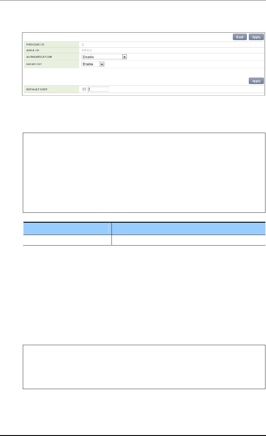
CHAPTER 3. Data Network Function
© SAMSUNG Electronics Co., Ltd. page 102 of 628
3.4.5.9 Summary Configuration
Configuration using CLI
WEC8500/configure/router/ospf 2# summary-address ?
A.B.C.D/M IP summary prefix
WEC8500/configure/router/ospf 2# summary-address 1.1.1.1/16 ?
not-advertise Suppress routes that match the prefix
tag Set tag
<cr>
WEC8500/configure/router/ospf 2# summary-address 1.1.1.1/16
WEC8500/configure/router/ospf 2#
Parameter
Description
summary-address
A.B.C.D/M
Operator can perform detail configuration only when you enter a summary-address.
The detail configuration includes advertise or TAG configuration.
1) Advertise Configuration
The default is set to Enable. Therefore, if no-advertise is selected in the CLI, the
configuration is changed to Disable.
2) Tag
A tag is a user-defined 32-bit tag value between 0 and 4294967295. A tag also has a
default value and it is 0.
WEC8500/configure/router/ospf 2# summary-address 11.1.1.1/16
WEC8500/configure/router/ospf 2# summary-address 11.1.1.1/16 tag ?
0 - 4294967295 32-bit tag value
WEC8500/configure/router/ospf 2# summary-address 11.1.1.1/16 tag 3
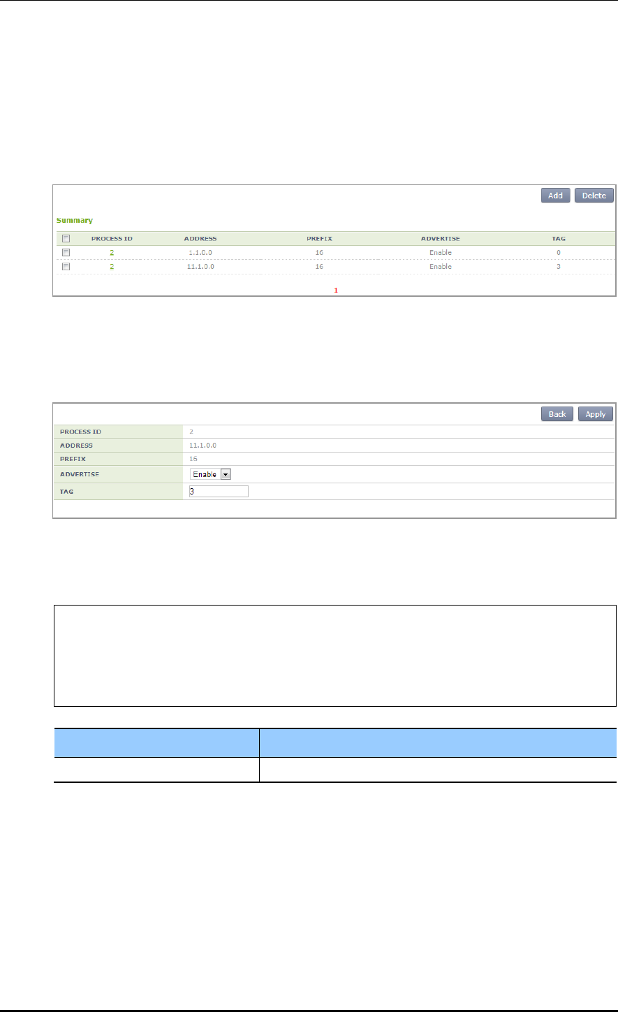
CHAPTER 3. Data Network Function
© SAMSUNG Electronics Co., Ltd. page 103 of 628
Configuration using Web UI
In the menu bar of <WEC Main window>, select <Configuration> and then select the
<Controller> <Network> <OSPF> <Summary> menu in the sub-menus.
The configuration page is as follows:
After default configuration, select a PROCESS ID for detail configuration.
The detail configuration includes advertise and TAG configuration mentioned in the CLI.
Unlike CLI, there is no no-advertise. A user can change the default Enable to Disable.
3.4.5.10 Passive Interface Configuration
Configuration using CLI
WEC8500/configure/router/ospf 2# passive-interface ?
<WORD> Interface's name
WEC8500/configure/router/ospf 2# passive-interface ge2 ?
A.B.C.D Address of interface
<cr>
Parameter
Description
Interface Name
Enter the name of an interface to use directly.
A user directly enters an interface name for Passive-interface configuration. Also, a user
can enter an address to the interface.
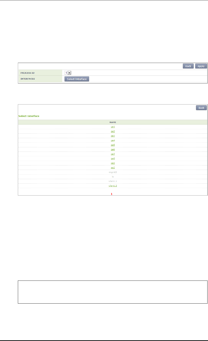
CHAPTER 3. Data Network Function
© SAMSUNG Electronics Co., Ltd. page 104 of 628
Configuration using Web UI
In the menu bar of <WEC Main window>, select <Configuration> and then select the
<Controller> <Network> <OSPF> <Passive Interface> menu in the sub-menus.
The configuration page is as follows:
After selecting a PROCESS ID that a user will use, select an interface to apply.
Among the interface items displayed on the screen, configure the interface that a user wants.
3.4.5.11 Interface General Configuration
Configuration using CLI
Unlike other OSPF configurations, the interface general does not enter into the OSPF mode.
Perform related configuration at the interface that a user wants. Therefore, the CLI
configuration is as follows:
1) Go to configure interface configuration mode of CLI.
WEC8500# configure terminal
WEC8500/configure#
WEC8500/configure# interface ge2
2) The items for detail configuration are as follows:

CHAPTER 3. Data Network Function
© SAMSUNG Electronics Co., Ltd. page 105 of 628
WEC8500/configure/interface ge2# ip ospf ?
address Address of interface
authentication Enable authentication
authentication-key Authentication password (key)
cost Interface cost
database-filter Filter OSPF LSA during synchronization
and flooding
dead-interval Interval after which a neighbor is
declared dead
disable Disable OSPF
hello-interval Time between HELLO packets
message-digest-key Message digest authentication password
(key)
mtu OSPF interface MTU
mtu-ignore Time between HELLO packets
network Network type
priority Router priority
retransmit-interval Time between retransmitting lost link
state advertisements
transmit-delay Link state transmit delay
DISABLE OSPF configuration
WEC8500/configure/interface ge2# ip ospf disable ?
all All functionality
WEC8500/configure/interface ge2# ip ospf disable all ?
<cr>
WEC8500/configure/interface ge2# ip ospf disable all
MTU configuration
The default does not use Maximum Transmission Unit (MTU) configuration.
The range of MTU user configuration is 576-65535.
WEC8500/configure/interface ge2# ip ospf mtu ?
576 - 65535
WEC8500/configure/interface ge2# ip ospf mtu 600
WEC8500/configure/interface ge2#
Network Type configuration
The network type includes 4 types, i.e. broadcast, non-broadcast, point-to-point, and
point-to-multipoint. The Ethernet is broadcast configuration.
WEC8500/configure/interface ge2# ip ospf network ?
broadcast Specify OSPF broadcast multi-access
network
non-broadcast Specify OSPF NBMA network

CHAPTER 3. Data Network Function
© SAMSUNG Electronics Co., Ltd. page 106 of 628
point-to-point Specify OSPF point-to-point network
point-to-multipoint Specify OSPF point-to-multipoint network
WEC8500/configure/interface ge2# ip ospf network
Authentication configuration
This is CLI that selects whether to use user authentication.
WEC8500/configure/interface ge2# ip ospf authentication ?
message-digest Use message-digest authentication
null Use null authentication
<cr>
WEC8500/configure/interface ge2# ip ospf authentication message-
digest ?
<cr>
WEC8500/configure/interface ge2# ip ospf authentication null ?
<cr>
WEC8500/configure/interface ge2# ip ospf authentication null
OSPF Cost configuration
Enter a cost value between 1 and 65535.
WEC8500/configure/interface ge2# ip ospf cost ?
1 - 65535 Cost
WEC8500/configure/interface ge2# ip ospf cost 2 ?
<cr>
DATABASE-FILTER configuration
WEC8500/configure/interface ge2# ip ospf database-filter ?
all Filter all LSA
WEC8500/configure/interface ge2# ip ospf database-filter all ?
out Outgoing LSA
WEC8500/configure/interface ge2# ip ospf database-filter all out ?
<cr>
WEC8500/configure/interface ge2# ip ospf database-filter all out
Dead-interval configuration
The default value of dead-interval is 4 times of hello-interval. Because the default
hello-interval is configured to 10 sec., the dead-interval will be 40 seconds if the hello-
interval is not configured. In addition, operator can change it to a value between 1
second and 65535 seconds.
WEC8500/configure/interface ge2# ip ospf dead-interval ?
1 - 65535 Seconds

CHAPTER 3. Data Network Function
© SAMSUNG Electronics Co., Ltd. page 107 of 628
WEC8500/configure/interface ge2# ip ospf dead-interval 30 ?
<cr>
WEC8500/configure/interface ge2# ip ospf dead-interval 30
Hello-interval configuration
The default hello-interval is 10 seconds. In addition, operator can change it to a value
between 1 second and 65535 seconds.
WEC8500/configure/interface ge2# ip ospf hello-interval ?
1 - 65535 Seconds
WEC8500/configure/interface ge2# ip ospf hello-interval 50 ?
<cr>
WEC8500/configure/interface ge2# ip ospf hello-interval 50
WEC8500/configure/interface ge2#
Retransmit-interval configuration
The default retransmit-interval is 5 seconds. In addition, operator can change it to a
value between 1 second and 65535 seconds.
WEC8500/configure/interface ge2# ip ospf retransmit-interval ?
1 - 65535 Seconds (default: 5)
WEC8500/configure/interface ge2# ip ospf retransmit-interval 100 ?
<cr>
WEC8500/configure/interface ge2# ip ospf retransmit-interval 100
WEC8500/configure/interface ge2#
TRANSMIT DELAY configuration
The default transmit-delay is 1 second. In addition, operator can change it to a value
between 1 second and 65535 seconds.
WEC8500/configure/interface ge2# ip ospf transmit-delay ?
1 - 65535 Seconds
WEC8500/configure/interface ge2# ip ospf transmit-delay 400
WEC8500/configure/interface ge2#
MTU IGNORE configuration
The default configuration is Disable. If you configure CLI, it is changed to Enable.
WEC8500/configure/interface ge2# ip ospf mtu-ignore ?
<cr>
WEC8500/configure/interface ge2# ip ospf mtu-ignore
WEC8500/configure/interface ge2#
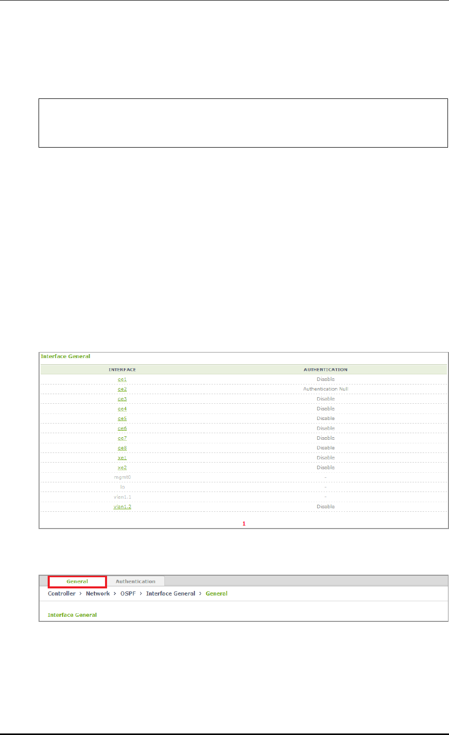
CHAPTER 3. Data Network Function
© SAMSUNG Electronics Co., Ltd. page 108 of 628
PRIORITY configuration
The default OSPF Priority value is 1. A user can configure the priority between 1 and
255.
WEC8500/configure/interface ge2# ip ospf priority ?
0 - 255 Priority
WEC8500/configure/interface ge2# ip ospf priority 2
Configuration using Web UI
In the menu bar of <WEC Main window>, select <Configuration> and then select the
<Controller> <Network> <OSPF> <Interface General> menu in the sub-
menus.
The configuration page is as follows:
As shown in the below figure, the currently enabled interface items are displayed.
When you select an interface for detail configuration, operator can go to the detail item
configuration page.
The Interface General item is also divided into General configuration and Authentication
window as a tab.
The General configuration screen is as follows:
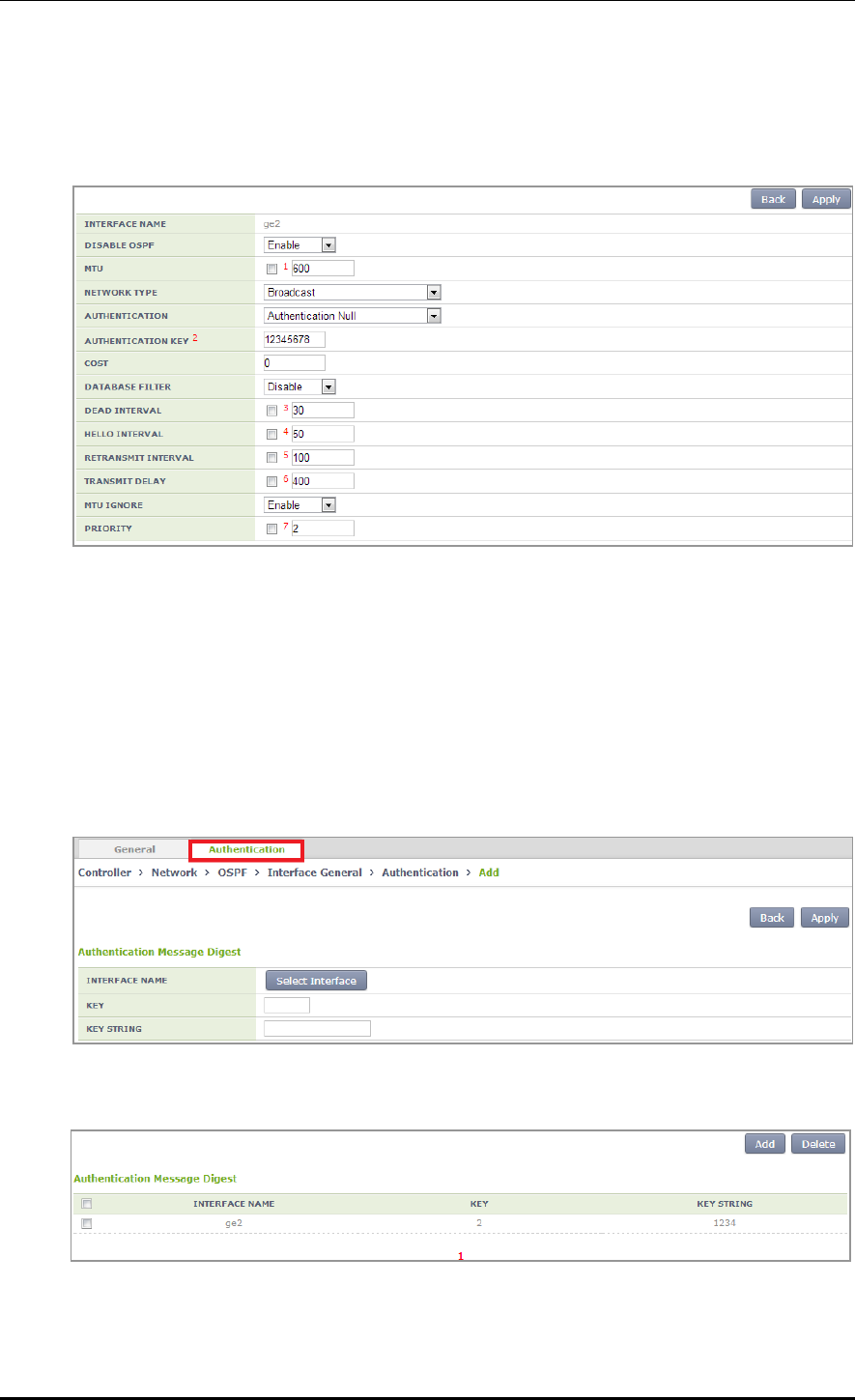
CHAPTER 3. Data Network Function
© SAMSUNG Electronics Co., Ltd. page 109 of 628
The detail item configuration page is as follows:
When you select the name of an enabled interface, the below detail item configuration page
is displayed.
After entering a value that a user wants for the item configured in the above CLI, click the
<Apply> button.
Authentication configuration
Just as General configuration, click the Authentication configuration in the tab.
Then, the page for authentication related detail configuration is displayed as shown below.
Select an interface that a user wants to configure, and enter the key string (1-255) of the
configuration.
The verification page after configuration is as follows:

CHAPTER 3. Data Network Function
© SAMSUNG Electronics Co., Ltd. page 110 of 628
3.4.6 VRRP Configuration
The Virtual Router Redundancy Protocol (VRRP) is an Internet protocol that provides the
backup router operation method in a LAN. If a fault occurs with a router that transmits a
packet from a host in a LAN, decide a virtual IP address in a DHCP manually or by default
by using a virtual router fault recovery protocol and share it among routers. Once a primary
router and a backup router are decided, the backup router becomes a primary router when a
fault occurs with the primary router.
Configuration using CLI
To configure the VRRP related function, go to configure router mode of CLI, enter a
router ID and interface name to go to the VRRP configuration mode.
WEC8500# configure terminal
WEC8500/configure# router
WEC8500/configure# router vrrp
WEC8500/configure# router vrrp 1 vlan1.10
WEC8500/configure/router/vrrp#
The following commands are provided.
[advertisement-interval]
This command configures the advertisement interval of VRRP in second. A user can
configure the interval from 1 to 10.
advertisement-interval [INTERVAL]
Parameter
Description
INTERVAL
Advertisement interval (range: 1-10 s)
[circuit-failover]
Enter an interface to configure and its priority.
circuit-failover [WORD] [PRIORITY]
Parameter
Description
WORD
Interface name
PRIORITY
Priority setup (range: 1-100)
[enable/disable]
This command enables or disables the VRRP session.
enable
disable

CHAPTER 3. Data Network Function
© SAMSUNG Electronics Co., Ltd. page 111 of 628
[preempt-delay]
This command configures the preempt delay time.
preempt-delay [DELAY_TIME]
Parameter
Description
DELAY_TIME
Preempt delay time (range: 0-3600 s)
[preempt-mode]
This command configures whether to use the preempt mode.
preempt-mode [MODE]
Parameter
Description
MODE
- true: Use the preempt mode
- false: Stop using the preempt mode.
[priority]
This command configures a priority.
priority [PRIORITY]
Parameter
Description
PRIORITY
Priority setup (range: 1-255)
[virtual-ip]
This command configures an IP address to use in the VRRP and configure the IP address as
master or backup.
virtual-ip [A.B.C.D]
virtual-ip [A.B.C.D] [MODE]
Parameter
Description
A.B.C.D
IP address
MODE
IP configuration mode (backup/master)
- backup: Backup router configuration.
- master: Master configuration.
[show vrrp]
This command retrieves VRRP configuration.
show vrrp
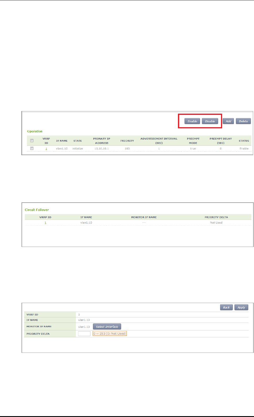
CHAPTER 3. Data Network Function
© SAMSUNG Electronics Co., Ltd. page 112 of 628
Configuration using Web UI
In the menu bar of <WEC Main window>, select <Configuration> and then select the
<Controller> <Network> <VRRP> menu in the sub-menus.
The VRRP menu provides two sub menus, i.e. Operation and Circuit Failover.
[Operation]
When you click the <Enable>/<Disable> button, you can Enable or disable VRRP.
In addition, when you click the <Add> or <Delete> button, you can add or delete VRRP
configuration.
Figure 35. VRRP-Operation Window
[Circuit Failover]
When you click the Circuit Failover menu, the VRRP list is displayed on the window.
Figure 36. VRRP-Circuit Failover Window (1)
To perform detail configuration, select one of VRRP items.
After selecting a configuration you want select the <Apply> button to apply the
configuration.
Figure 37. VRRP-Circuit Failover Window (2)
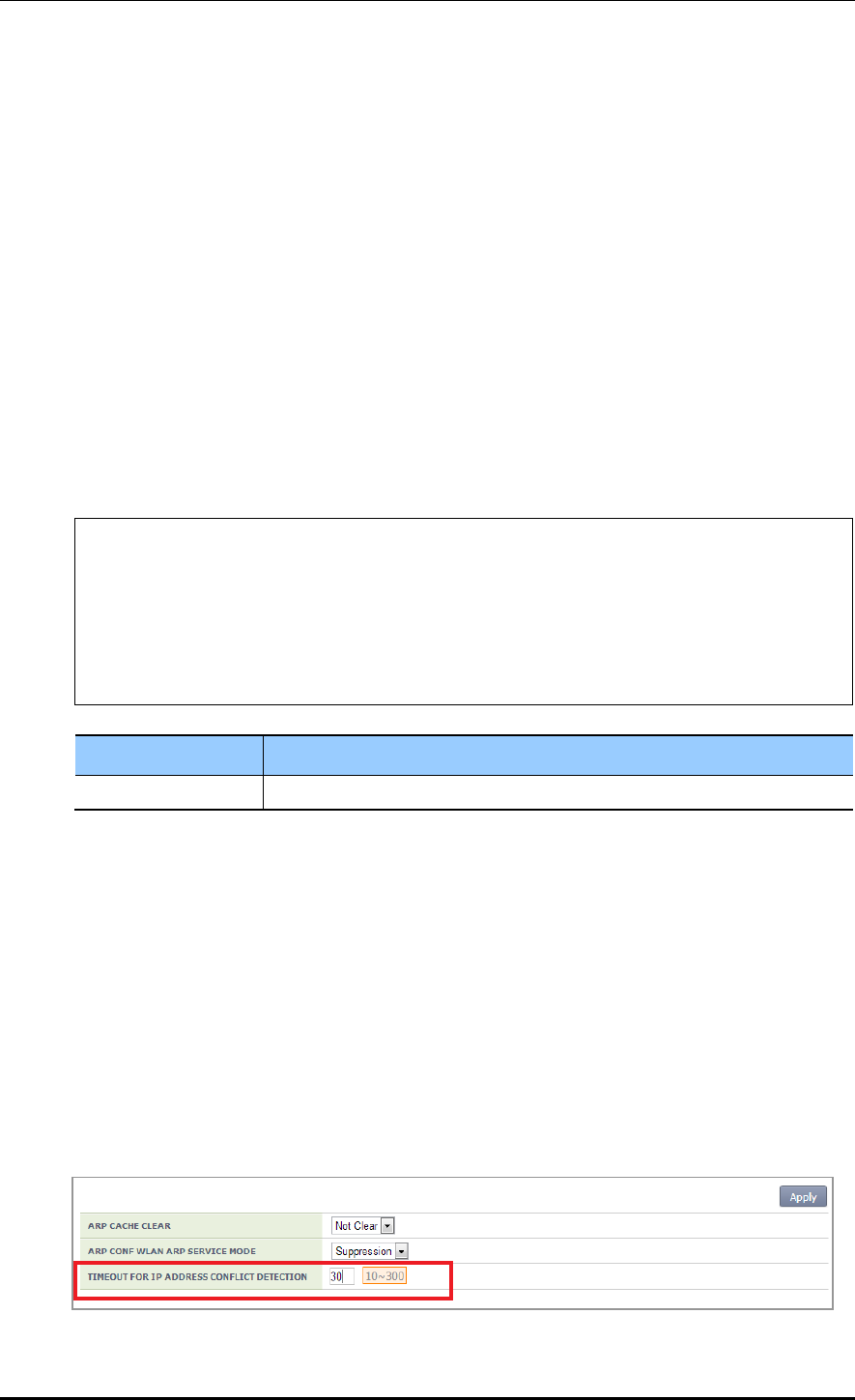
CHAPTER 3. Data Network Function
© SAMSUNG Electronics Co., Ltd. page 113 of 628
3.4.7 Configuring IPWATCHD
The IP WATCH Deamon (IPWATCHD) provides the function of detecting active or passive
IP collision. Regardless of IP collision attacker or victim, the information including source
ip/mac is transmitted as an evm fault event when the IP collision occurs. At the collision
time, the Gratuitous Address Resolution Protocol (GARP) reply is transmitted 3 times to
the unicast at every 1 second.
It supports the rate-limit function to deal with an intended ARP attack. Although ARP is
entered from a host that is not in the same subnet, it generates GARP by recognizing it as a
target if the host has the same APC IP.
Configuration using CLI
To configure the IPWATCHD function, enter into the configure mode of CLI.
Configure a TIMEOUT value (that a user wants) to detect an IP address collision.
Operator can enter a value between 10 and 300 seconds.
WEC8500# configure terminal
WEC8500/configure#
WEC8500/configure# ipwatch ?
defend-interval Ipwatch defend-interval configuration
WEC8500/configure# ipwatch defend-interval ?
10 - 300 Ipwatch defend-interval value(seconds)
WEC8500/configure# ipwatch defend-interval 30
Parameter
Description
VALUE
Enter a defend-interval (10-300 sec).
The default TIMEOUT value for IP address collision detection is 30 seconds.
When the time is configured, the IPWATCHD daemon is restarted and a log and GARP is
generated if there is an IP collision.
Configuration using Web UI
In the menu bar of <WEC Main window>, select <Configuration> and then select the
<Controller> <Network> <ARP> menu in the sub-menus.
After entering a time value (10-300 seconds) that a user wants in the TIMEOUT FOR IP
ADDRESS CONFLICT DETECTION window, click the <Apply> button. Then, the
configuration is applied.
The default value before user configuration is 30 as shown in the below figure.
Figure 38. IPWATCHD Configuration Window

CHAPTER 3. Data Network Function
© SAMSUNG Electronics Co., Ltd. page 114 of 628
3.5 QoS
The Access Control List (ACL) allows or blocks a specific network traffic based on an
operator’s configuration. The APC provides QoS using ACL.
3.5.1 ACL Configuration
3.5.1.1 Access List Configuration
You can create or delete an access list for ACL configuration. To delete an access list, an
operator can enter the name of an access list directly or enter a command by copying a
value retrieved from the ‘show running-config network’. But, if the access list is being used
in the WLAN ACL or Admin ACL, etc., you cannot delete it. Therefore, check if it is being
used in the WLAN ACL or Admin ACL first of all.
Configuration using CLI
1) Go to fqm mode where you can configure the configure rule of CLI.
APC# configure terminal
APC/configure# fqm-mode
2) Create an access list by entering the ‘access-list’ command. The ‘no’ parameter is used
to delete an access list.
access-list [ip/ipv6/mac] [ACL_NAME] [deny/permit/time-profile] seq [seq_NUM]
[1/*/ahp/eigrp/esp/gre/icmp/igmp/igrp/ip/nos/ospf/pcp/pim/17/6/
tcp/udp/1-255] [any/A.B.C.D A.B.C.D] eq [eq_VALUE] [any/A.B.C.D A.B.C.D] eq
[eq_VALUE] [[[dscp [*|[0-63]]|precedence [*|[0-7])]]]|]
An example of entering a command is shown below.
Creating Access list ‘acl1’:
APC# configure terminal
APC/configure# fqm-mode
APC/configure# access-list ip acl1 permit seq 1 icmp any any
Deleting Access list ‘acl1’:
APC# configure terminal
APC/configure# fqm-mode
APC/configure# no access-list ip acl1 permit seq 1 icmp any any
3) Check a created access list using the ‘show running-config network’ command.
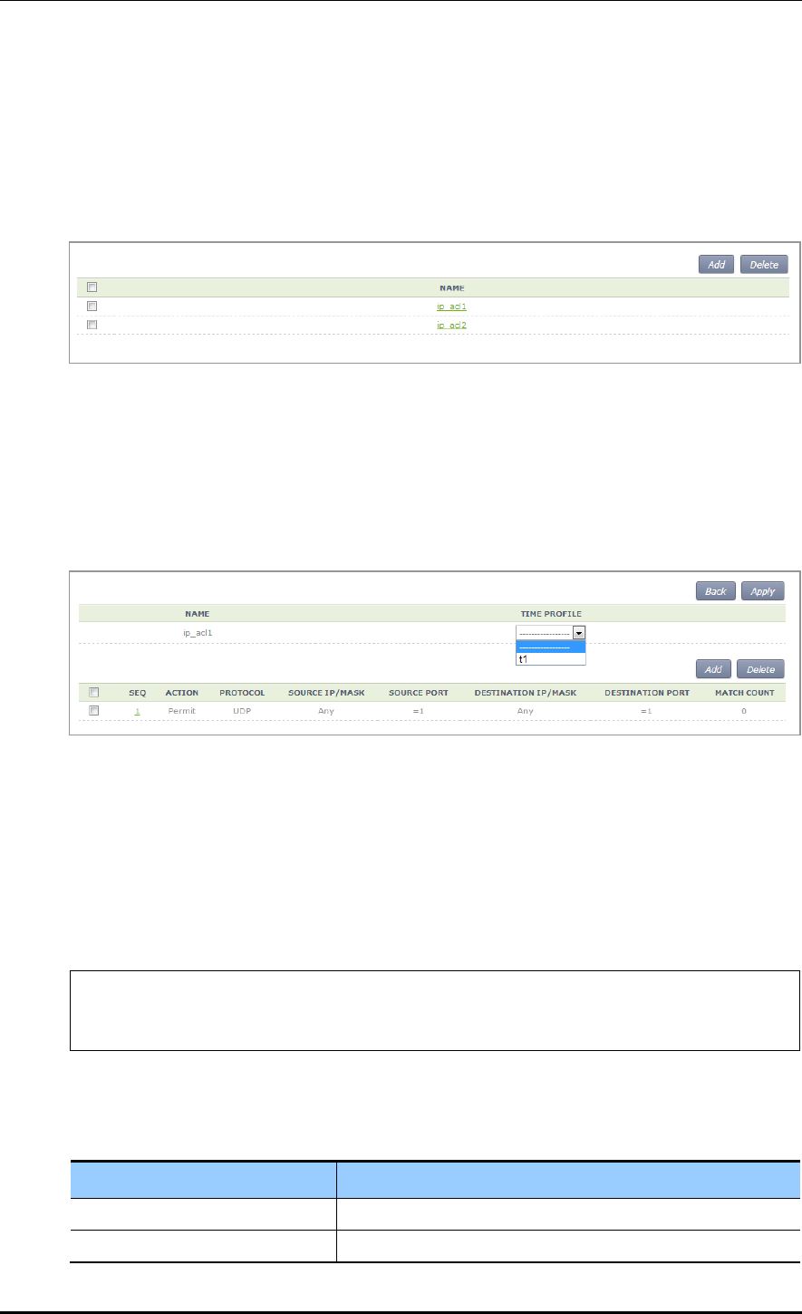
CHAPTER 3. Data Network Function
© SAMSUNG Electronics Co., Ltd. page 115 of 628
Configuration using Web UI
In the menu bar of <WEC Main window>, select <Configuration> and then select the
<Security> <Access Control Lists> <IP ACL> menu in the sub-menus.
The initial window of ACL rule configuration is shown below. When you click the <Add>
or <Delete> button, you can add or delete ACL rule.
Figure 39. ACL Configuration Window
To change the configuration of ACL rule, click ACL NAME to change. You can change the
configuration using the <Add> or <Delete> button. In addition, if there is a time profile in
an ACL name, the IP ALC window is changed as shown below. After selecting a time
profile, click the <Apply> button to apply the time profile to the ACL.
Figure 40. Window where a Time Profile is Applied to ACL
3.5.1.2 ACL Rule Configuration
Configuration using CLI
1) Go to interface configuration mode where you will apply the configure ACL rule of
CLI.
APC# configure terminal
APC/configure# interface [name]
APC/configure/interface [name]#
2) Configure ACL to an interface.
ip access-group [MODE] [DIRECTION] [ACL_NAME]
Parameter
Description
MODE
Configuration mode (fw/fqm)
DIRECTION
Application direction configuration (in/out)
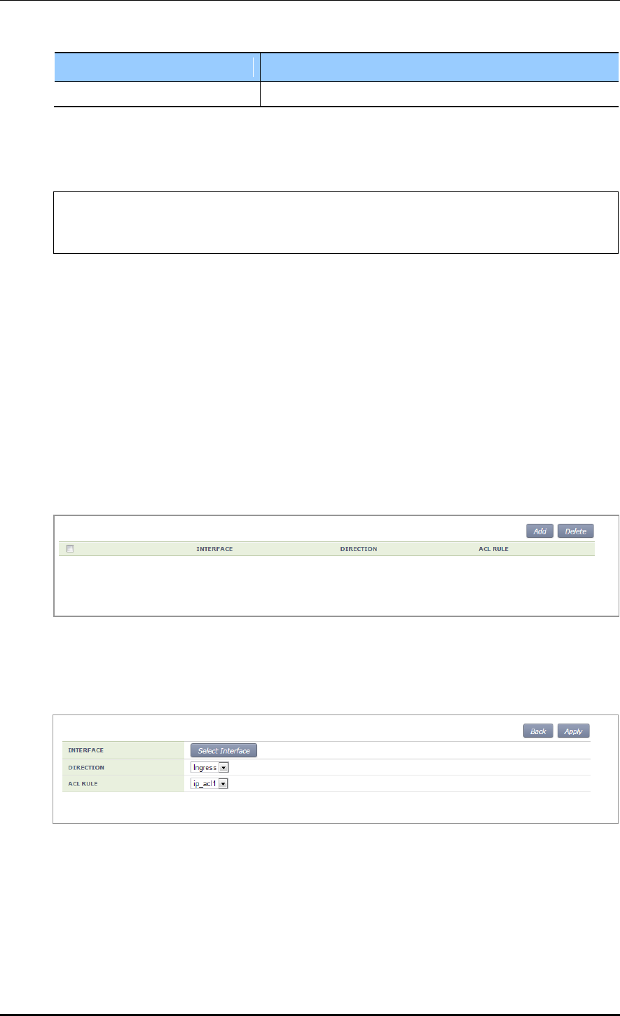
CHAPTER 3. Data Network Function
© SAMSUNG Electronics Co., Ltd. page 116 of 628
Parameter
Description
ACL_NAME
ACL name to configure
An example of entering a command that configures ‘acl1’ to the ‘ge2’ interface is
shown below.
APC# configure terminal
APC/configure# interface ge2
APC/configure/interface ge2#ip access-group fqm in acl1
3) To check the configuration information, use the ‘show running-config network’
command.
Configuration using Web UI
In the menu bar of <WEC Main window>, select <Configuration> and then select the
<Security> <Access Control Lists> <Access Group (Interface)> menu in the sub-
menus.
The initial window of WLAN ACL configuration is shown below. When you click the
<Add> or <Delete> button, you can add or delete ACL rule.
Figure 41. ACL Interface Configuration Window (1)
To perform detail configuration, select an interface in the list.
Figure 42. ACL Interface Configuration Window (2)
The types of interfaces you can configure are retrieved. In the INTERFACE, select an
interface. For DIRECTION, select Ingress or Egress. For ACL NAME, select an item
(name) that is configured in the ACL List configuration.
To apply the changed configuration, click the <Apply> button.

CHAPTER 3. Data Network Function
© SAMSUNG Electronics Co., Ltd. page 117 of 628
3.5.1.3 WLAN ACL Configuration
1) Go to the fqm mode to configure the configure ACL rule of CLI.
APC# configure terminal
APC/configure# fqm-mode
2) Configure WLAN ACL by entering the ‘ip access-group wireless’ command.
ip access-group wireless [ACL_NAME]
Parameter
Description
ACL_NAME
ACL name to configure
3) To check the configuration information, use the ‘show running-config network’
command.
3.5.1.4 Admin ACL Configuring
Configuration using CLI
1) Go to the fqm mode to configure the configure ACL rule of CLI.
APC# configure terminal
APC/configure# fqm-mode
2) Configure Admin ACL by entering the ‘ip access-group wireless’ command.
ip access-group system [ACL_NAME]
Parameter
Description
ACL_NAME
ACL name to configure
3) To check the configuration information, use the ‘show running-config network’
command.
Configuration using Web UI
In the menu bar of <WEC Main window>, select <Configuration> and then select the
<Security> <Access Control Lists> <Access Group (System)> menu in the sub-
menus.
The initial window of Access Group is shown below. After selecting a configuration, click
the <Apply> button to configure Admin ACL.

CHAPTER 3. Data Network Function
© SAMSUNG Electronics Co., Ltd. page 118 of 628
Figure 43. Admin ACL Configuration Window
3.5.2 Class-map Configuration
1) Go to the fqm mode to configure the configure ACL rule of CLI.
APC# configure terminal
APC/configure# fqm-mode
2) Go to Class-map mode.
class-map c1
3) Select match-all or match-any.
match-type [MODE]
Parameter
Description
MODE
Match mode configuration (match-all/match-any)
4) Perform detail configuration according to match criteria.
Match Criteria
Description
access-group
match access-group [ACCESS_GROUP_NAME]
class
match class [CLASS_NAME]
COS
match cos [COS_VALUE/any]
destination IP range
match dst ip range [A.B.C.D] [A.B.C.D]
IP
match ip dscp [DSCP_VALUE/any]
match ip precedence [IP_PRECEDENCE_VALUE/any]
match ip tos [TOS_VALUE/any]
protocol
match protocol [PROTOCOL_VALE/any]
source IP range
match src ip range [A.B.C.D] [A.B.C.D]
5) Exit the Class-map mode.
exit
6) To check the configuration information, use the ‘show running-config network’
command.

CHAPTER 3. Data Network Function
© SAMSUNG Electronics Co., Ltd. page 119 of 628
3.5.3 Policy-map Configuration
1) Go to the fqm mode to configure the configure ACL rule of CLI.
APC# configure terminal
APC/configure# fqm-mode
2) Go to policy-map mode. To delete a policy map, enter ‘no’ parameter in front of the
command.
policy-map [POLICY_MAP_NAME]
no policy-map [POLICY_MAP_NAME]
3) By using the class name configured in the class-map, go to the input mode.
class [CLASSMAP_NAME]
4) Configure a policy-map using the following command.
[Bandwidth to a class of traffic]
bandwidth percentage [PERCENTAGE_VALUE]
[Configure set action]
mark cos [COS_VALUE]
mark ip dscp [DSCP_VALUE]
mark ip precedence [PRECEDENCE_VALUE]
mark priority [PRIORITY_VALUE]
[Configure police action]
police trtcm cir [1-1000] cbs [125000-125000000] pir [1-1000] pbs [125000-
125000000] conform-action(drop|(dscp [0-63]|ip [0-7])|transmit) exceed-
action(drop|(dscp [0-63]|ip [0-7])|transmit) violate-action(drop|(dscp [0-63]|ip [0-
7])|transmit)(color-aware|color-blind|)
[Peak rate to a class of traffic]
queue-limit [QUEUE_NUM]
[Peak rate to a class of traffic]
shape-peak [PEAK_RATE]
5) Exit the policy-map mode.
exit
6) To check the configuration information, use the ‘show running-config network’
command.

CHAPTER 3. Data Network Function
© SAMSUNG Electronics Co., Ltd. page 120 of 628
3.5.4 Service Policy Configuration
Apply the policy configured in the policy-map to an interface.
1) Go to configure interface configuring mode to apply the service policy of CLI.
APC# configure terminal
APC/configure# interface ge2
APC/configure/interface ge2#
2) Apply the policy configured in the policy-map to an interface. The ‘no’ parameter is
used to delete the policy.
service-policy [DIRECTION] [POLICY_NAME]
no service-policy [DIRECTION] [POLICY_NAME]
Parameter
Description
DIRECTION
Application direction configuration (in/out)
POLICY_NAME
Policy to apply
An example of entering a command is shown below.
APC/configure/interface ge2# service-policy in p1
APC/configure/interface ge2# no service-policy in p1
3) To check the configuration information, use the ‘show running-config network’
command.
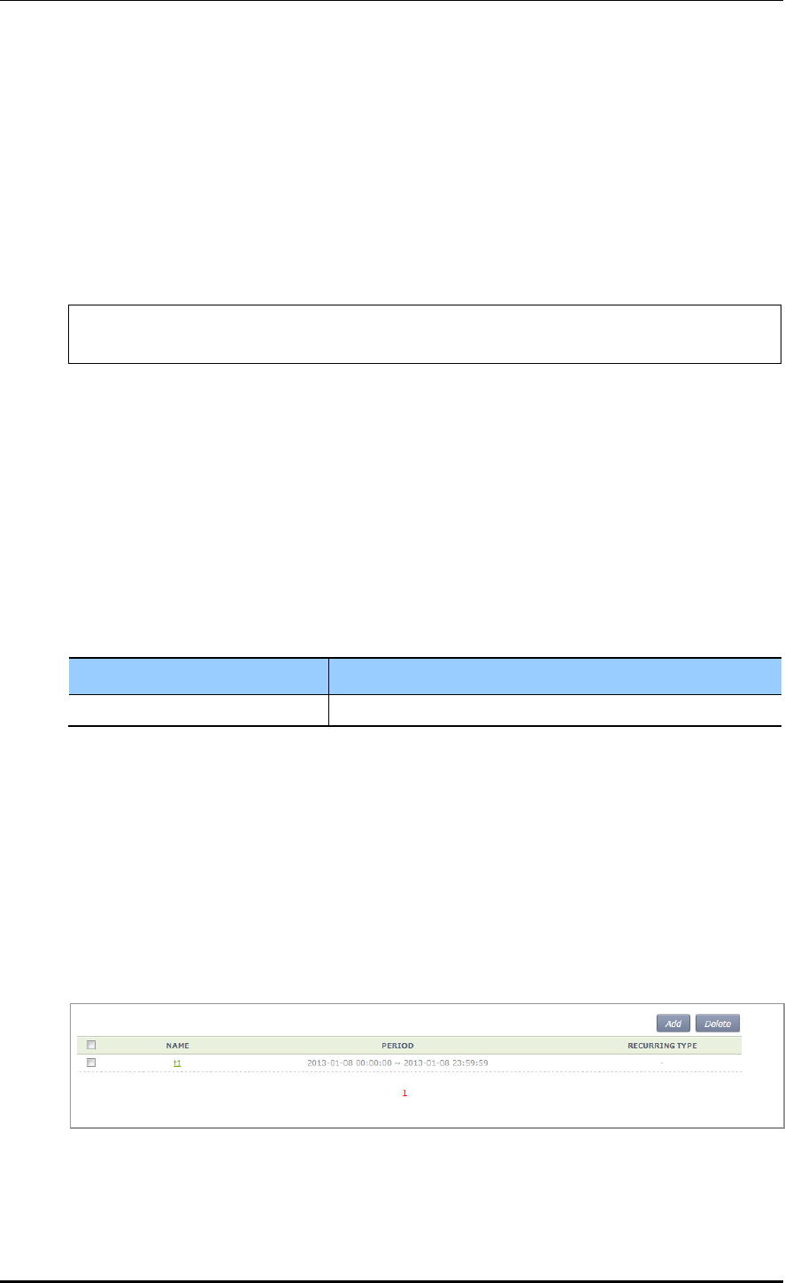
CHAPTER 3. Data Network Function
© SAMSUNG Electronics Co., Ltd. page 121 of 628
3.5.5 Time Profile
The procedure of configuring a time profile and applying it to ACL is described.
3.5.5.1 Time Profile Configuration
Configuration using CLI
1) Go to configure of CLI fqm mode.
APC# configure terminal
APC/configure# fqm-mode
2) Configure a time profile. The ‘no’ parameter is used to delete a time profile.
time-profile [PROFILE_NAME]
day-start (any|YY[-MM[-DD[THH[:MM[:SS]]]]])
day-stop (any|YY[-MM[-DD[THH[:MM[:SS]]]]])
time-start (any|HH:MM[:SS])
time-stop (any|HH:[MM:SS])
monthdays (any|[0-31])
weekdays (any|VARIABLE))
no time-profile [PROFILE_NAME]
Parameter
Description
PROFILE_NAME
Name of a time profile to configure
3) To check the configured time profile, use the ‘show running-config network’ command.
Configuration using Web UI
In the menu bar of <WEC Main window>, select <Configuration> and then select the
<Security> <Access Control Lists> <Time Profile> menu in the sub-menus.
The configured time profile list is displayed on the window. When you click the <Add> or
<Delete> button, you can add or delete a time profile.
Figure 44. Time Profile Configuration Window (1)
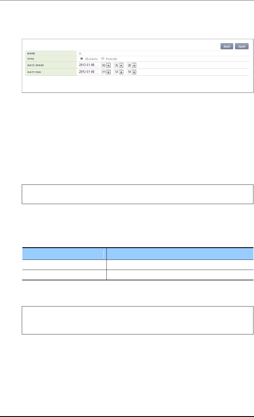
CHAPTER 3. Data Network Function
© SAMSUNG Electronics Co., Ltd. page 122 of 628
Select an item in the list and perform detail configuration.
Figure 45. Time Profile Configuration Window (2)
After finishing configuration in the window, click the <Apply> button to apply it to the
system.
3.5.5.2 Applying to ACL
Configuration using CLI
1) Go to the fqm mode to configure the configure ACL rule of CLI.
APC# configure terminal
APC/configure# fqm-mode
2) Apply a time-profile to ACL. The ‘no’ parameter is used to delete a time profile.
access-list ip [ACL_NAME] time-profile [PROFILE_NAME]
no access-list ip [ACL_NAME] time-profile [PROFILE_NAME]
Parameter
Description
ACL_NAME
ACL name to configure
PROFILE_NAME
Name of a time profile to configure
An example of applying ‘t1’ to ‘acl’ is shown below.
APC# configure terminal
APC/configure# fqm-mode
access-list ip acl1 time-profile t1
3) To check the configuration information, use the ‘show running-config network’
command.
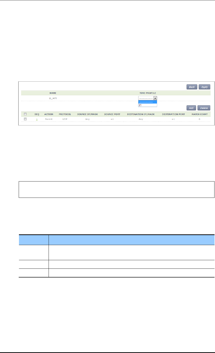
CHAPTER 3. Data Network Function
© SAMSUNG Electronics Co., Ltd. page 123 of 628
Configuration using Web UI
In the menu bar of <WEC Main window>, select <Configuration> and then select the
<Security> <Access Control Lists> <IP ACL> menu in the sub-menus.
To change the configuration of ACL rule, click ACLNAME to change. You can change the
configuration using the <Add> or <Delete> button. In addition, if there is a time profile in
an ACL name, the IP ACL window is changed as shown below. After selecting a time
profile, click the <Apply> button to apply the time profile to the ACL.
Figure 46. Applying to ACL
3.5.5.3 ACL (Time-Profile) Rule Configuration
Configuration using CLI
1) Go to configure interface configuration mode of CLI.
APC# configure terminal
APC/configure# interface ge2
2) Configure ACL to the interface. The ‘no’ parameter is used to delete ACL.
ip access-group [MODE] [DIRECTION] [ACL_NAME]
no ip access-group [fw/fqm] [DIRECTION] [ACL_NAME]
Parameter
Description
MODE
Configuration mode (fw/fqm)
For ACL rule configuration, select ‘fqm’ (The ‘fw’ is used for firewall configuration.)
DIRECTION
Application direction configuration (in/out)
ACL_NAME
ACL name to configure
3) To check the configuration information, use the ‘show running-config network’ command.
Configuration using Web UI
In the menu bar of <WEC Main window>, select <Configuration> and then select the
<Security> <Access Control Lists> <Access Group (Interface)> menu in the sub-
menus.
Perform configuration by referring to ‘ACL Rule Configuration’.

CHAPTER 3. Data Network Function
© SAMSUNG Electronics Co., Ltd. page 124 of 628
3.5.6 OS-AWARE
OS-AWARE is a function to use the option value of the DHCP Discover/Request
transmitted from a station to check the type of the operating system used by the station.
The procedures to set OS-AWARE and apply the OS-AWARE settings to ACL are
described below.
3.5.6.1 OS-AWARE Configuration
Configuration using CLI
1) Go to configure os-aware mode of CLI.
APC# configure terminal
APC/configure# os-aware
APC/configure/os-aware # ?
delete Os-aware delete operation
exit Exit from os-aware mode
os-aware Os-aware add operation
update Os-aware update
2) Set the OS-AWARE. Use the ‘delete’ parameter to delete the OS-AWARE.
os-aware [OS_AWARE NAME] dhcp-option [OPTION_NUM] dhcp-option
[OPTION_NUM] eq[VALUE] os-type [OS_TYPE NAME]
delete os-aware [OS_AWARE NAME]
update os-aware [OS_AWARE NAME] dhcp-option [OPTION_NUM] dhcp-option
[OPTION_NUM] eq [VALUE] os-type [OS_TYPE NAME]
Parameter
Description
OS_AWARE NAME
os-aware name to configure
SEQUENCE_NUM
Fingerprint pattern match sequence(1~255)
OPTION_NUM
dhcp option value (1~255)
VALUE
Fingerprint value(HEX)
OS_TYPE NAME
os-type name to configure(Unknown, android, ios, windows, mac)
os-aware ‘window7’ creation:
APC# configure terminal
APC/configure# os-aware
APC/configure/os-aware # os-aware window7 seq 5 dhcp-option 1 eq AA
os-type windows

CHAPTER 3. Data Network Function
© SAMSUNG Electronics Co., Ltd. page 125 of 628
os-aware ‘window7’ modification:
APC# configure terminal
APC/configure# os-aware
APC/configure/os-aware # os-aware window7 seq 8 dhcp-option 2 eq FF
os-type windows
os-aware ‘window7’ deletion:
APC# configure terminal
APC/configure# os-aware
APC/configure/os-aware # no os-aware window7
3) Check the settings by using the ‘show OS-AWARE-all’ or ‘show OS-AWARE-
[OS_AWARE NAME]’ commands.
‘show OS-AWARE-all’ retrieves all OS-AWARE information and ‘show OS-AWARE-
[OS_AWARE NAME]’ only retrieves user defined information out of all OS-AWARE
information.
======================================================================
=========================
PLD_INDEX OS_NAME TYPE REFCNT OPTION LENGTH FINGERPRINT
OS_TYPE
======================================================================
=========================
1 window7 0 0 5 2 1234 windows
3.5.6.2 Applying to ACL
Configuration using CLI
1) Go to configure fqm mode to set the ACL rule of CLI.
APC# configure terminal
APC/configure# fqm-mode
2) Apply the OS-AWARE to ACL. Use the ‘no’ parameter to delete the OS-AWARE
access-list [ip/ipv6/mac] [ACL_NAME] [deny/permit/time-profile] seq [seq_NUM]
[1/*/ahp/eigrp/esp/gre/icmp/igmp/igrp/ip/nos/ospf/pcp/pim/17/6/tcp/udp/1-255]
[any/A.B.C.D A.B.C.D] eq [eq_VALUE] [any/A.B.C.D A.B.C.D] eq [eq_VALUE]
os-aware[OS_AWARE NAME] [[[dscp [*|[0-63]]|precedence [*|[0-7])]]]|]
no access-list [ip/ipv6/mac] [ACL_NAME] [deny/permit/time-profile] seq
[seq_NUM] [1/*/ahp/eigrp/esp/gre/icmp/igmp/igrp/ip/nos/ospf/pcp/pim/17/6/tcp/
udp/1-255] [any/A.B.C.D A.B.C.D] eq [eq_VALUE] [any/A.B.C.D A.B.C.D] eq
[eq_VALUE] os-aware[OS_AWARE NAME] [[[dscp [*|[0-63]]|precedence [*|[0-
7])]]]|]

CHAPTER 3. Data Network Function
© SAMSUNG Electronics Co., Ltd. page 126 of 628
Parameter
Description
OS_AWARE NAME
os-aware name to configure
An example of applying ‘window7’ to ‘acl’ is as follows.
APC# configure terminal
APC/configure# fqm-mode
access-list ip acl1 permit seq 1 icmp any any os-aware window7
3) To check the configuration information, use the ‘show running-config network’
command.
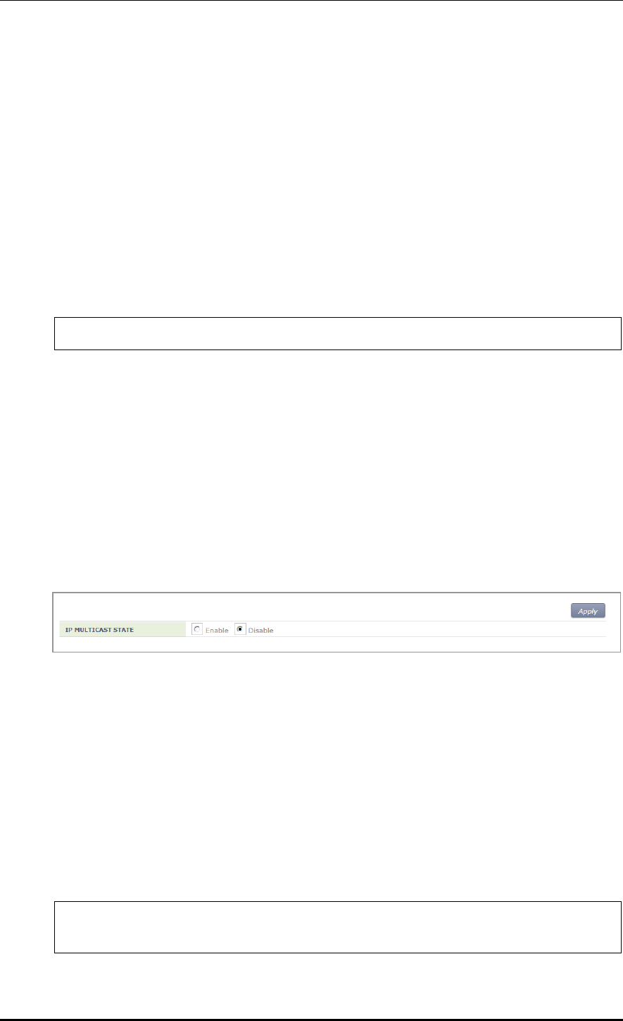
CHAPTER 3. Data Network Function
© SAMSUNG Electronics Co., Ltd. page 127 of 628
3.6 Multicast to Unicast
Execute the ‘show multi2uni-list’ command to check the list of wireless terminals that use
the multicast to unicast function.
3.7 IP Multicast Configuration
3.7.1 IP Multicast Routing Configuration
Configuration using CLI
1) Go to configure mode of CLI.
WEC8500# configure terminal
2) Enable or disable the routing function for IP multicast.
ip multicast-routing: Enable
no ip multicast-routing: Disable
Configuration using Web UI
In the menu bar of <WEC Main window>, select <Configuration> and then select the
<Controller> <Multicast> <IP Multicast> menu in the sub-menus.
After selecting Enable/Disable in the IP Multicast window, click the <Apply> button to
apply the configuration.
Figure 47. IP Multicast Configuration Window
3.7.2 PIM Configuration
As a multicast layer3 transmission protocol, the PIM has two modes, i.e. Dense mode and
Sparse mode. The WEC8500 supports only PIM Sparse mode and the PIM Sparse mode
can be configured for each interface.
Configuration using CLI
1) Go to configure of CLI mode where you want to perform configuration.
WEC8500# configure terminal
WEC8500/configure# interface ge2
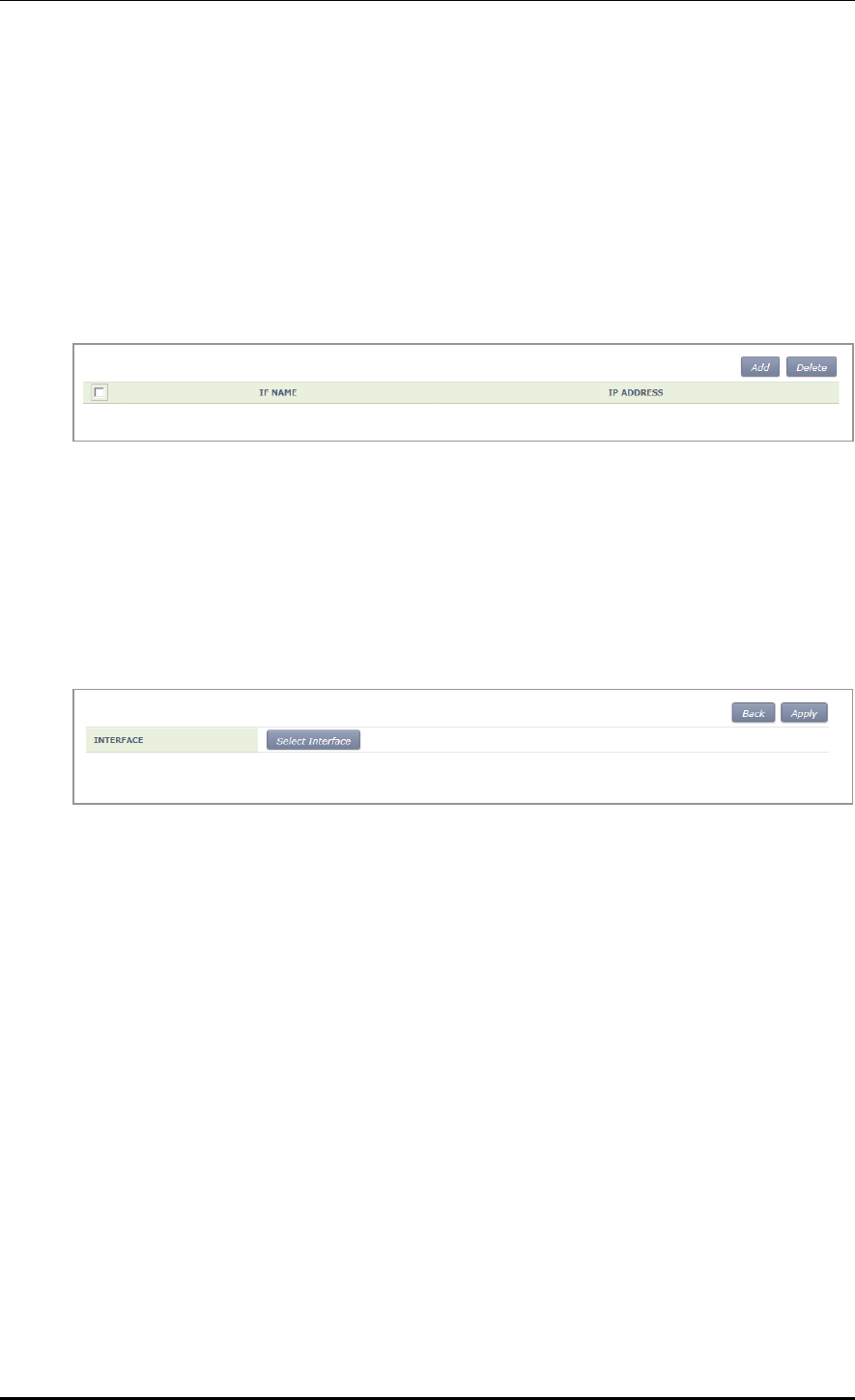
CHAPTER 3. Data Network Function
© SAMSUNG Electronics Co., Ltd. page 128 of 628
2) Perform PIM configuration.
ip pim sparse-mode: Enable
no ip pim sparse-mode: Disable
Configuration using Web UI
In the menu bar of <WEC Main window>, select <Configuration> and then select the
<Controller> <Multicast> <PIM-SM> menu in the sub-menus. When you click the
<Add> or <Delete> button, you can add or delete PIM-SM configuration.
Figure 48. PIM-SM Configuration Window (1)
Follow the below procedure to add a PIM.
1) In the PIM-SM initial window, click the <Add> button.
2) Click the <Select Interface> button.
Figure 49. PIM-SM Configuration Window (2)
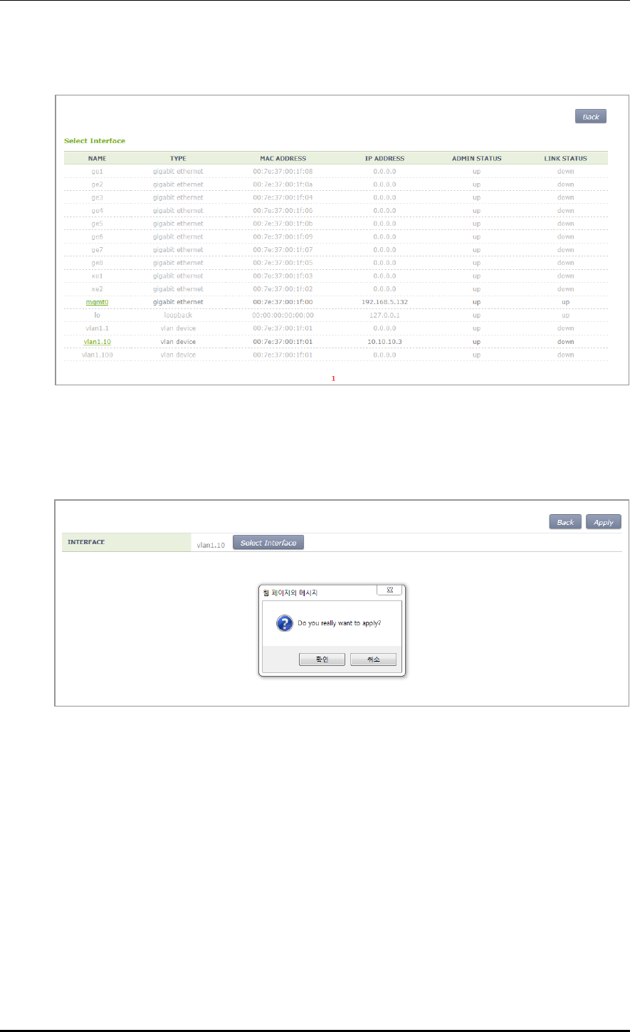
CHAPTER 3. Data Network Function
© SAMSUNG Electronics Co., Ltd. page 129 of 628
3) Select an interface to add.
Figure 50. PIM-SM Configuration Window (3)
4) The selected interface is displayed on the window. Click the <Apply> button to apply
the configuration.
Figure 51. PIM-SM Configuration Window (4)

CHAPTER 3. Data Network Function
© SAMSUNG Electronics Co., Ltd. page 130 of 628
3.8 IGMP Snooping
Configuration using CLI
Use the ‘ip igmp snooping’ command to enable or disable Internet Group Management
Protocol (IGMP) Snooping.
ip igmp snooping
no ip igmp snooping
When this command is executed in the Configure mode, the IGMP Snooping of a bridge is
enabled or disabled. If it is executed in the interface mode, the IGMP Snooping of an
interface is enabled or disabled.
Configuring the IGMP Snooping of a bridge:
WEC8500# configure terminal
WEC8500/configure# ip igmp snooping
Configuring the IGMP Snooping of a VLAN interface:
WEC8500# configure terminal
WEC8500/configure# interface vlan1.10
WEC8500/configure/interface vlan1.10# ip igmp snooping
In addition, a specific function of the IGMP Snooping functions of a VLAN interface can
be enabled or disabled as shown in the below command.
[ip igmp snooping fast-leave]
This command enables or disables the Fast-Leave function. (Default: Enable status)
ip igmp snooping fast-leave
no ip igmp snooping fast-leave
[ip igmp snooping querier]
This command enables or disables the Querier function. (Default: Enable status)
ip igmp snooping querier
no ip igmp snooping querier
[ip igmp snooping report-suppression]
This command enables or disables the Report-suppression function. (Default: Enable
status)
ip igmp snooping report-suppression
no ip igmp snooping report-suppression
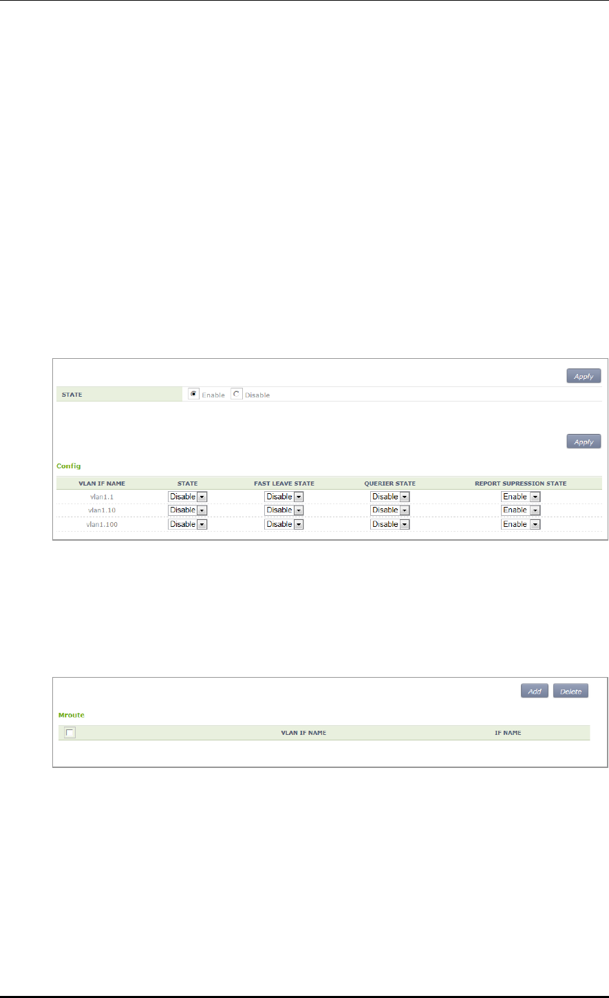
CHAPTER 3. Data Network Function
© SAMSUNG Electronics Co., Ltd. page 131 of 628
[ip igmp snooping mroute]
This command enables or disables the Mroute function.
ip igmp snooping mroute [INTERFACE]
no ip igmp snooping mroute [INTERFACE]
Configuration using Web UI
In the menu bar of <WEC Main window>, select <Configuration> and then select the
<Controller> <Multicast> <IGMP Snooping> menu in the sub-menus.
[Config]
Enables or disables the IGMP Snooping function or configures related functions.
To perform configuration for STATE, FAST LEAVE, QUERIER STATE, or REPORT
SUPRESSION STATE, select Enable or Disable and click the <Apply> button.
Figure 52. IGMP Snooping Config Window
[Mroute]
The PIM-SM initial window is shown below. When you click the <Add> or <Delete>
button, you can add or delete PIM-SM configuration.
Figure 53. IGMP Snooping Mroute Creation Window (1)
1) In the PIM-SM initial window, click the <Add> button.
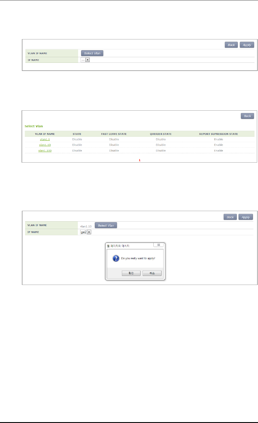
CHAPTER 3. Data Network Function
© SAMSUNG Electronics Co., Ltd. page 132 of 628
2) Click the <Select Vlan> button.
Figure 54. IGMP Snooping Mroute Creation Window (2)
3) Select a VLAN interface that will be added to the Mroute.
Figure 55. IGMP Snooping Mroute Creation Window (3)
4) The selected interface is displayed on the window. Click the <Apply> button to apply
the configuration.
Figure 56. IGMP Snooping Mroute Creation Window (4)

CHAPTER 3. Data Network Function
© SAMSUNG Electronics Co., Ltd. page 133 of 628
3.9 Deep Packet Inspection
It supports QoS by application. It may allow drop, bandwidth contract, and DSCP marking
and it provides statistics by detailed category. The application of DPI in a unit of WLAN is
possible and it also provides a monitoring function.
3.9.1 Configuring Profile and Application Rule
A profile is a set of application rules and each rule includes the QoS settings of the
application.
The profile must set at least one application rule.
Configuration using CLI
1) Enter the DPI Configuration mode.
APC# configure terminal
APC/configure# dpi
APC/configure/dpi#
2) Make a profile and add an application rule.
APC/configure/dpi# profile [NAME]
APC/configure/dpi/profile [NAME]# rule [APPLICATION]
APC/configure/dpi/profile [NAME]/rule [APPLICATION]# action permit
APC/configure/dpi/profile [NAME]/rule [APPLICATION]# mark [DSCP]
APC/configure/dpi/profile [NAME]/rule [APPLICATION]# bw-contract
upstream [BW_CNT]
APC/configure/dpi/profile [NAME]/rule [APPLICATION]# bw-contract
downstream [BW_CNT]
APC/configure/dpi/profile [NAME]# enable
Parameter
Description
NAME
Profile name
APPLICATION
Application name
DSCP
DSCP value
BW_CNT
Bandwidth Contract. Kbps
3) Designate a WLAN where the profile is applied.
APC# configure terminal
APC/configure# wlan [ID]
APC/configure/wlan [ID]# dpi-profile [NAME]

CHAPTER 3. Data Network Function
© SAMSUNG Electronics Co., Ltd. page 134 of 628
Parameter
Description
NAME
Profile name
ID
WLAN ID
3.9.2 Configuring Application Group
Possible to configure one or more applications as a group.
Configuration using CLI
1) Enter the DPI Configuration mode.
APC# configure terminal
APC/configure# dpi
APC/configure/dpi#
2) Make a group and add an application.
APC/configure/dpi# app-group [NAME]
APC/configure/dpi/app-group [NAME]# application [APPLICATION]
Parameter
Description
NAME
Group name
APPLICATION
Application name
3.9.3 Checking Statistics by Category
The category provides statistical information by application, WLAN, station, device-os-
type, and group.
Configuration using CLI
1) Check the statistical information on all applications.
APC# show dpi stat application
Accumulated Application Stat
-------------------------------------------------------------------
----------------------------------------------------------------------
---------

CHAPTER 3. Data Network Function
© SAMSUNG Electronics Co., Ltd. page 135 of 628
| ID | Application Name | Upstream Packet Count |
Upstream Byte | Downstream Packet Count | Downstream Byte |
| | * | |
Upstream Kbps | | Downstream Kbps |
| | ** | Drop |
Drop | Drop | Drop |
-------------------------------------------------------------------
----------------------------------------------------------------------
---------
| 1 | BITTORRENT | 0 |
0 | 0 | 0 |
| 3 | FTP_DATA | 0 |
0 | 0 | 0 |
| 4 | TELNET | 0 |
0 | 0 | 0 |
| 5 | TFTP | 0 |
0 | 0 | 0 |
| 6 | VIMEO | 0 |
0 | 0 | 0 |
| 7 | YAHOO_MSG_VOIP | 0 |
0 | 0 | 0 |
| 8 | YOUTUBE | 1 |
54 | 2 | 220 |
| 9 | VSHARE | 0 |
0 | 0 | 0 |
| 10 | FLASH_YAHOO | 0 |
0 | 0 | 0 |
| 11 | BING | 0 |
0 | 0 | 0 |
| 12 | DNS | 0 |
0 | 0 | 0 |
| 13 | FLASH | 0 |
0 | 0 | 0 |
| 14 | FTP | 0 |
0 | 0 | 0 |
| 15 | GMAIL | 0 |
0 | 0 | 0 |
| 17 | GOOGLE | 0 |
0 | 0 | 0 |
| 18 | GOOGLE_EARTH | 0 |
0 | 0 | 0 |
| 19 | GOOGLE_GROUPS | 0 |
0 | 0 | 0 |
| 20 | GOOGLE_MAPS | 0 |
0 | 0 | 0 |
| 21 | HTTP | 0 |
0 | 0 | 0 |
| 22 | HTTP_SECURE | 3 |
162 | 3 | 193 |
| 23 | TWITTER | 0 |
0 | 0 | 0 |

CHAPTER 3. Data Network Function
© SAMSUNG Electronics Co., Ltd. page 136 of 628
| 24 | YAHOO_MAIL | 0 |
0 | 0 | 0 |
| 25 | YAHOO_SEARCH | 0 |
0 | 0 | 0 |
| 26 | ORKUT | 0 |
0 | 0 | 0 |
| 27 | FACEBOOK | 0 |
0 | 0 | 0 |
| 28 | LINKEDIN | 0 |
0 | 0 | 0 |
| 29 | VOICETALKSIGNAL | 0 |
0 | 0 | 0 |
| 30 | KAKAOTALK_VOIP | 0 |
0 | 0 | 0 |
| 51 | COMMON_PATTERNS | 0 |
0 | 0 | 0 |
-------------------------------------------------------------------
----------------------------------------------------------------------
---------
Top 10 Applications
-------------------------------------------------------------------
----------------------------------------------------------------------
---------
| RANK | ID | Application Name | Upstream Packet Count |
Upstream Byte | Downstream Packet Count |
Downstream Byte |
----------------------------------------------------------------------
----------------------------------------------------------------------
------
| 1 | 22 | HTTP_SECURE | 3 |
162 | 3 |
193 |
| 2 | 8 | YOUTUBE | 1 |
54 | 2 |
220 |
----------------------------------------------------------------------
----------------------------------------------------------------------
------
APC#
2) Check the statistical information on specific applications.
APC# show dpi stat application HTTP_SECURE
- "HTTP_SECURE"(ID: 22) Stat
| Description
| ""
| Upstream Packet Count ......................
3 packets
| Upstream Byte ..............................
162 bytes
| Downstream Packet Count ....................

CHAPTER 3. Data Network Function
© SAMSUNG Electronics Co., Ltd. page 137 of 628
3 packets
| Downstream Byte ............................
193 bytes
| Upstream Packet Drop Count .................
0 packets
| Upstream Drop Byte .........................
0 bytes
| Downstream Packet Drop Count ...............
0 packets
| Downstream Drop Byte .......................
0 bytes
|
| Top 10 Stations |----1----2--
--3----4----5----6----7----8----9---|%
| 1. 00:12:47:F3:CF:A4 100.00% 355 bytes
||||||||||||||||||||||||||||||||||||||||||||||||||
|
| Top 10 Stations(History) |----1----2--
--3----4----5----6----7----8----9---|%
|
| Top 10 WLANs |----1----2--
--3----4----5----6----7----8----9---|%
| 1. 1 100.00% 355 bytes
||||||||||||||||||||||||||||||||||||||||||||||||||
|
| Top 10 Device types |----1----2--
--3----4----5----6----7----8----9---|%
| 1. Samsung SM-P900 100.00% 355 bytes
||||||||||||||||||||||||||||||||||||||||||||||||||
|
| Top 10 OS types |----1----2--
--3----4----5----6----7----8----9---|%
| 1. Android 4.4.2 100.00% 355 bytes
||||||||||||||||||||||||||||||||||||||||||||||||||
APC#
Parameter
Description
APPLICATION
Application name
3) Check the statistical information on all WLANs.
APC# show dpi stat wlan
4 ) Check the statistical information on specific WLANs.
APC# show dpi stat wlan [ID]

CHAPTER 3. Data Network Function
© SAMSUNG Electronics Co., Ltd. page 138 of 628
Parameter
Description
ID
WLAN ID
5) Check the statistical information on all stations.
APC# show dpi stat station
6) Check the statistical information on specific stations.
APC# show dpi stat station [MAC]
파라미터
설명
MAC
Station MAC
7) Check the statistical information on all device-os-types.
APC# show dpi stat device-os-type
8) Check the statistical information on specific device-os-types.
APC# show dpi stat device-os-type [TYPE]
Parameter
Description
TYPE
Device of OS type name
9) Check the statistical information on all application groups.
APC# show dpi stat group
10) Check the statistical information on specific application groups.
APC# show dpi stat group [NAME]
Parameter
Description
NAME
Application group name

CHAPTER 4. AP Connection Management
© SAMSUNG Electronics Co., Ltd. page 139 of 628
CHAPTER 4. AP Connection
Management
This chapter describes the various configuration methods to manage the connection
between the APC and AP.
4.1 APC Management
4.1.1 Managing APC List
To enable the APC system to provide the cluster or redundancy service, several APC
systems must be installed at a site and each APC must have the information of other APC
systems.
Therefore, the APC system provides the function of managing the list of APCs that will
provide the cluster or redundancy function. And the APCs added to the APC list are used
during cluster or redundancy configuration.
One APC system that will be saved in the APC list consists of an APC name and Medium
Access Control (MAC) information. For the MAC address of another APC system, enter
the MAC address retrieved from the Monitor Summary Inventory MAC Address
menu of system WEC screen.
By default, its own system information is added to the APC list. For the APC, operator can
only change its name, but cannot delete it forcibly or change its MAC address.
The maximum number of APC systems that can be registered per model is as follows:
APC Model
The maximum number of APC systems that can be registered
WEC8500
12
WEC8050
2
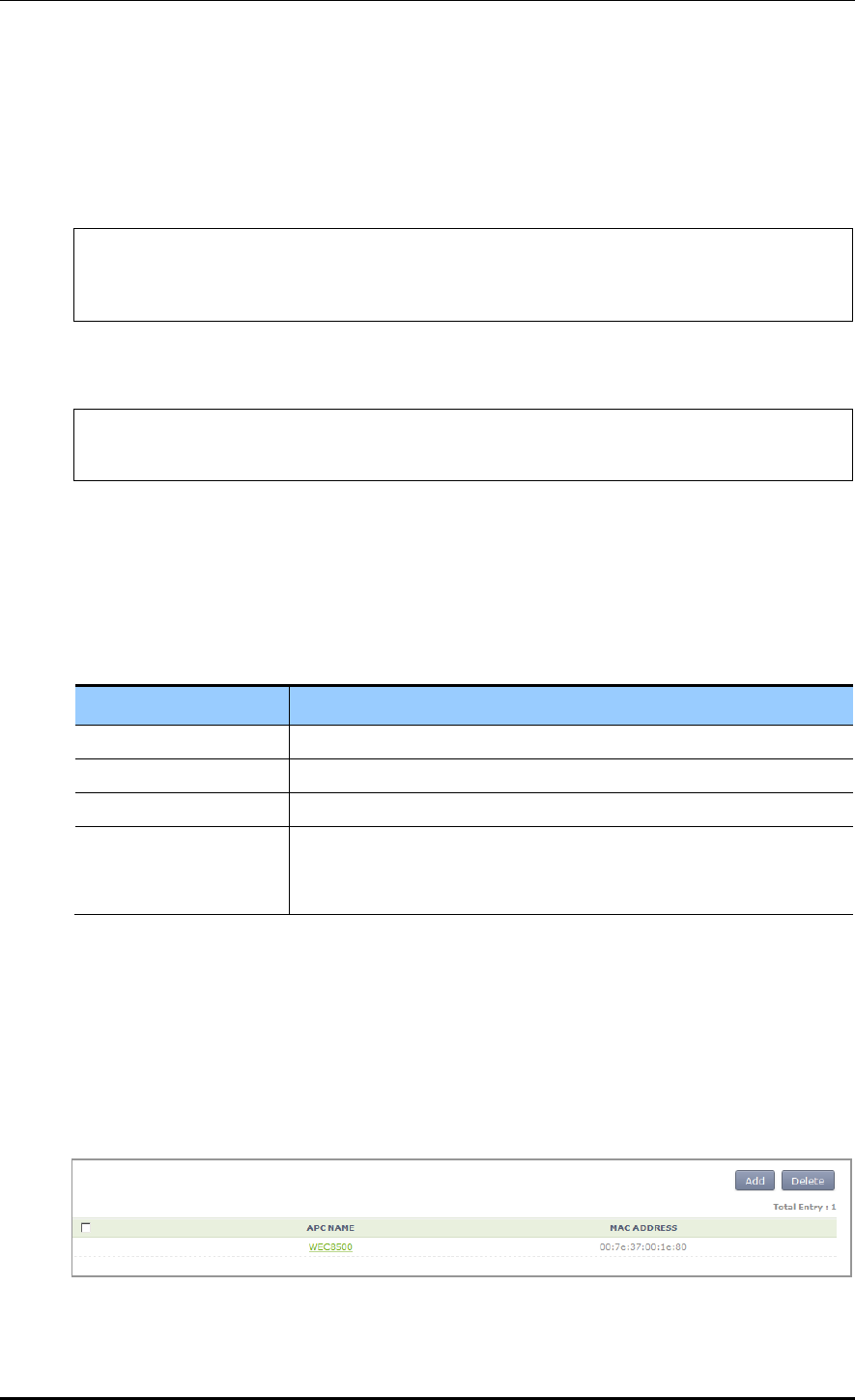
CHAPTER 4. AP Connection Management
© SAMSUNG Electronics Co., Ltd. page 140 of 628
Configuration using CLI
The procedures for configuration are as follows.
1) Go to configure mode of CLI.
WEC8500# configure terminal
WEC8500/configure# apc
WEC8500/configure/apc/apc-list#
2) Go to the apc-list item of CLI.
WEC8500/configure# apc
WEC8500/configure/apc/apc-list#
3) Add, delete or change APC.
add-apc [APC_NAME] [MAC_ADDRESS]
del-apc [APC_NAME]
change-apc [CURRENT_APC_NAME] [NEW_APC_NAME]
change-mac [APC_NAME] [MAC_ADDRESS]
Parameter
Description
APC_NAME
APC name
CURRENT_APC_NAME
Current APC name (before change)
NEW_APC_NAME
APC name after change
IP_ADDRESS
APC MAC address (xx:xx:xx:xx:xx:xx)
In the APC system, enter the system mac address output parameter
value of ‘show system info’ command.)
4) To check the configured APC list, execute the ‘show apc-list’ command.
Configuration using Web UI
In the menu bar of <WEC Main window>, select <Configuration> and then select the
<Controller> <APC Lists> menu in the sub-menus. Operator can add a new APC by
clicking the <Add> button in the figure.
Figure 57. APC List Management Window
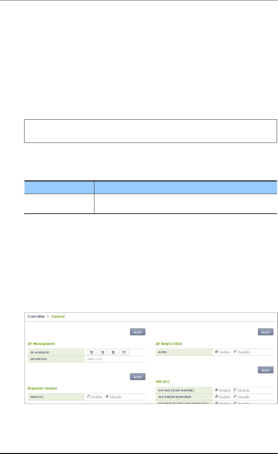
CHAPTER 4. AP Connection Management
© SAMSUNG Electronics Co., Ltd. page 141 of 628
4.1.2 Management Interface Configuration
The APC can communicate with a W-EP wireless LAN AP using management interface.
This is one of the information that must be configured first of all for wireless LAN service.
Configuration using CLI
To configure management interface, execute the command as follows:
1) Go to configure mode of CLI.
WEC8500# configure terminal
WEC8500/configure#
2) Configure a management interface.
apc ap-mgmt-if [IP_ADDRESS]
Parameter
Description
IP_ADDRESS
IP address of APC that is used for communication with a W-EP
wireless LAN AP
3) To check the configured IP information, use the ‘show apc summary’ command.
Configuration using Web UI
In the menu bar of <WEC Main window>, select <Configuration> and then select the
<Controller> <General> menu in the sub-menus.
After entering a configuration in the AP Management of the window, click the <Apply>
button.
Figure 58. Management interface configuration

CHAPTER 4. AP Connection Management
© SAMSUNG Electronics Co., Ltd. page 142 of 628
4.1.3 CAPWAP Configuration
A secured tunnel is created between APC and W-EP wireless LAN AP using Control And
Provisioning Wireless Access Point (CAPWAP), i.e. a standard protocol, and data is
transmitted through the tunnel. An encrypted data is used for both wire and wireless
sections, high security is provided.
The CAPWAP channel consists of control channel and data channel depending on the type
of packet being transmitted/received. The control channel handles provisioning and
configuration/control messages and the data channel transmits the data traffic exchanged
with a wireless terminal through CAPWAP tunneling. Because the control channel
transmits the wireless LAN configuration information, there should be no data loss.
Therefore, the re-transmission function is basically provided. In addition, the Datagram
Transmission Layer Security (DTLS) is mandatorily used for the security of transmitted
data. Meanwhile, as user data traffic is transmitted through the data channel, a faster
response is preferred instead of packet transmission reliability. Therefore, the re-
transmission function is not provided and the DTLS function is also optional.
For CAPWAP configuration, execute the following commands.
1) Go to configure apc capwap of CLI.
WEC8500# configure terminal
WEC8500/configure# apc
WEC8500/configure/apc/capwap#
WEC8500# configure terminal
WEC8500/configure# apc
WEC8500/configure/apc/capwap#
2) Configure the CAPWAP function using the following commands.
add-multicast-if [VLAN_ID]: Configure a VLAN ID for multicast interface.
auto-discovery: Configures the function of automatically detecting and registering
an AP.
auto-discovery-ap-group [AP_GROUP_ID]: Configures an AP group that will be
working when an AP is automatically registered.
change-state-pending-timer [TIMER]: Configures the maximum waiting time until
the APC receives the Change State Event Request message from an AP after
transmitting the Configuration Status Response message to the AP (RFC 5415).
ctr-src-port [port]: Changes the CAPWAP Control port (RFC5415).
date-check-timer [TIMER]: Configures the maximum waiting time until the APC
receives Data Channel Keep-alive (default: 30 seconds)
discovery-by-broadcast: Configures whether to allow connection to CAPWAP
broadcast.

CHAPTER 4. AP Connection Management
© SAMSUNG Electronics Co., Ltd. page 143 of 628
discovery-by-multicast: Configures whether to allow connection to CAPWAP
multicast. (The ‘add-multicast-if’ must be configured before configuring whether to
allow multicast connection.)
discovery-del-timer: If the Join message is not received after receiving a Discovery
message, this configures the timeout to discard the previously received Discovery
messages.
dtls-session-delete [TIMER]: Configures the waiting time to disconnect DTLS when
releasing the connection between an AP and CAPWAP.
retransmit-interval [INTERVAL]: Configures the re-transmission interval of
CAPWAP control packet retransmission.
max-retransmit [COUNT]: Configures maximum number of retransmission when
there is no answer for CAPWAP control packet transmission.
wait-dtls-timer [TIMER]: Configures the maximum time until the AP waits without
receiving the DTLS handshake message from the APC (RFC 5415) (default: 60
seconds)
wait-join-timer [TIMER]: Configures the maximum time until the APC receives the
Join message after finishing DTLS handshake (RFC 5415) (default: 60 seconds)
window-size [size]: Configures the maximum number of packets that can be
transmitted without response during CAPWAP control packet transmission.
An example of entering a command is shown below.
WEC8500/configure/apc/capwap# date-check-timer 30
3) To check the configured CAPWAP information, use the ‘show apc capwap summary’
command.
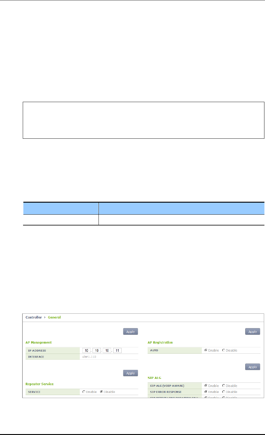
CHAPTER 4. AP Connection Management
© SAMSUNG Electronics Co., Ltd. page 144 of 628
4.1.4 AP Registration (Auto Discovery) Configuration
The APC provides the AP auto-discovery function that automatically registers APs in the
same network without having to configure any settings in advance. To configure the
function, execute the following commands.
Configuration using CLI
1) Go to configure apc capwap of CLI.
WEC8500# configure terminal
WEC8500/configure# apc
WEC8500/configure/apc # capwap
WEC8500/configure/apc/capwap #
2) Configure the automatic registration function.
auto-discovery
3) Configure an AP group that will be working after AP automatic registration.
auto-discovery-ap-group [AP_GROUP_ID]
Parameter
Description
AP_GROUP_ID
ap-group that will be working after AP automatic registration
4) To check the configured information, use the ‘show apc capwap summary’ command.
Configuration using Web UI
In the menu bar of <WEC Main window>, select <Configuration> and then select the
<Controller> <General> menu from the sub-menus.
After entering a configuration in the AP Registration of the window, click the <Apply>
button.
Figure 59. AP Registration Method Setup Window

CHAPTER 4. AP Connection Management
© SAMSUNG Electronics Co., Ltd. page 145 of 628
4.1.5 Managing AP File Transmission
It provides the configuration and transmission management function for the tech support
file of the AP.
4.1.5.1 Tech Support Information File
1) Go to configure APC mode of CLI.
WEC8500# configure terminal
WEC8500/configure# apc
WEC8500/configure/apc#
2) Configure a file transmission method to collect the AP Tech support information.
tech-support [MODE]
Parameter
Description
MODE
Selects file transmission method (ftp/sftp/http).
- tftp is not supported.
3) If AP debug information collection is failed, configure maximum number of retries.
tech-support max-retry [COUNT]
Parameter
Description
COUNT
Number of retries.
4) To check the configuration information, use the ‘show ap tech-support’ command.
4.1.6 APC Redundancy Configuration
An operator can add a backup APC to an AP to make the backup APC provide the service
even when an APC fault occurs.
The maximum number of backup APCs that can be registered to one AP per model is as
follows:
APC Model
The maximum number of APC systems that can be registered
WEC8500
3 (Primary Server, Secondary Server, Tertiary Server)
WEC8050
2 (Primary Server, Secondary Server)
If a fault occurs to the primary APC while an AP is connected to the primary APC, the AP
is connected to the secondary APC. If a fault also occurs to the secondary APC, the AP is
connected to the tertiary APC. For reference, the WEC8050 model does not support a
tertiary APC.

CHAPTER 4. AP Connection Management
© SAMSUNG Electronics Co., Ltd. page 146 of 628
Operator can also configure fallback to return to the original APC from the backup APC
during the service. If the fallback operation is configured, the AP periodically performs
health check to check whether the primary APC can be connected. When the connection is
required, it can immediately perform fallback according to the fallback option or can
perform fallback on a specified time. The reason why configuring fallback time zone is to
minimize the service interruption due to fallback by making it happens when the load is
low.
In an APC, operator can configure the primary and backup APCs of an AP in the following
steps.
1) Register APCs to the APC list.
In the ‘APC List Management’, how to add the APC list is described.
2) Add the APCs in the APC list to redundancy.
If necessary, configure the fallback function.
And then, operator can configure the APCs added to redundancy as the primary,
secondary, or tertiary server of an AP.
3) Configure a primary, secondary, and tertiary server per AP. To make an AP operate in
redundancy configuration, configure the Discovery Type of the AP as ‘APC Referal’.
Use the Multi-Set function of WEC to configure several APs at the same time.
Configuration using CLI
1) By referring to the ‘AP List Management’, add the APC list that will be used as a
backup APC.
2) After entering into the configure redundancy mode, add or delete the APCs in the
APC list. If necessary, configure the fallback function.
WEC8500# configure terminal
WEC8500/configure# redundancy
WEC8500/configure/redundancy#
add-apc [APC_NAME] [IP_ADDRESS] [PORT]
del-apc [APC_NAME]
fallback-enable now
fallback-enable at-time [FALLBACK START-END TIME]
fallback-interval [INTERVAL]
Parameter
Description
APC_NAME
Name of an APC to be added or deleted to/from redundancy
The APC must be an APC registered in the APC list.
IP_ADDRESS
IP address of an APC to add
This address is an IP required by an AP to connect to the APC.
Therefore, you must enter the AP Management IP address of the APC.

CHAPTER 4. AP Connection Management
© SAMSUNG Electronics Co., Ltd. page 147 of 628
Parameter
Description
PORT
CAPWAP PORT number of the APC to add
This port number is required by an AP to connect to the APC. If no port
number is entered, it is set to 5246, the default port number of CAPWAP
protocol. It is recommended not to use a different port number if it is
specially required.
FALLBACK START-
END TIME
Enter the time zone where an AP connected to the backup (secondary or
tertiary) APC can do fallback.
The input format is as follows:
- Format: hh:mm-hh:mm
- Example: 2:00-5:00 Fallback is available between 2pm and 5pm.
INTERVAL
Configures the interval that an AP connected to the backup (secondary or
tertiary) APC attempts fallback (second).
If a specific time is not entered, the default is 120 seconds.
The minimum is 60 seconds and the maximum is 1800 seconds.
3) Enter into the configure AP configuration mode of CLI and configure a primary,
secondary, and tertiary server. To make an AP operate in redundancy configuration,
configure the Discovery of the AP as ‘apc-referal’.
WEC8500# configure terminal
WEC8500/configure# ap ap_1
WEC8500/configure/ap ap_1#
discovery apc-referal
primary-apc [APC_NAME]
secondary-apc [APC_NAME]
tertiary-apc [APC_NAME]
Parameter
Description
APC_NAME
Enter the name of an APC registered to redundancy.
- Primary apc: The first APC that the AP attempts to connect.
It is usually configured with the currently connected APC.
- Secondary-apc, tertiary-apc: APC that the AP attempts to connect when
there is no response from the primary-apc.
DISCOVERY_TYPE
Discovery Type
- ap-followed: Discovery type is set by AP.
- apc-referal: Discovery type is set by APC using the backup APC lists.
To apply the priority of APC to which the AP will be connected, operator
needs to select the apc-referal.
- DHCP: Discovery type is interoperating with the DHCP server. To use this
mode, IP ADDRESS POLICY of the AP must be set to DHCP.
- Auto: Discovery type is automatically changed by the AP for automatic
connection to the APC.
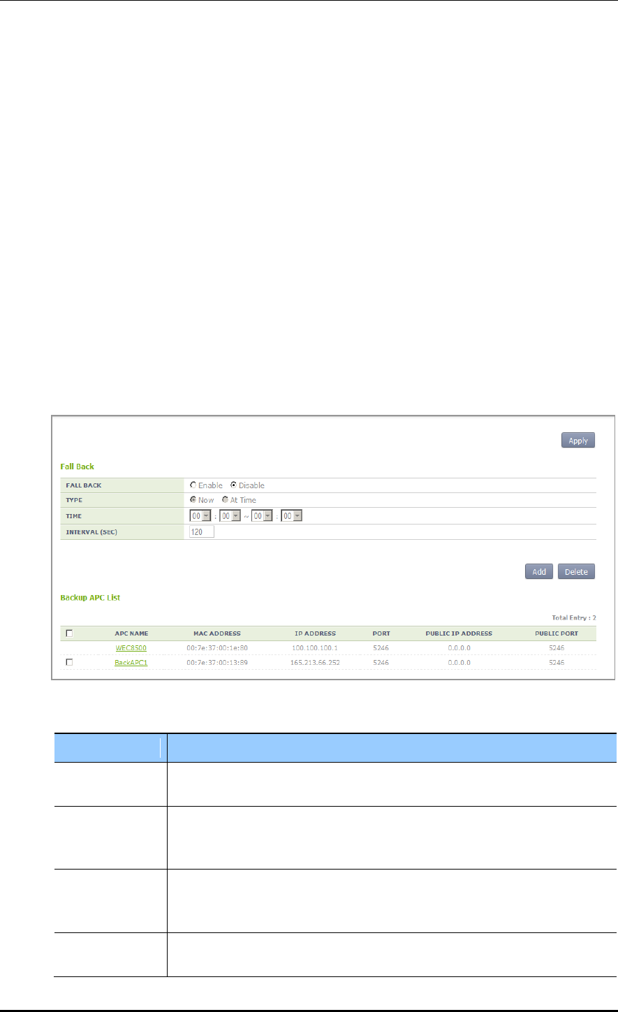
CHAPTER 4. AP Connection Management
© SAMSUNG Electronics Co., Ltd. page 148 of 628
4) To check the configured apc list, execute the ‘show apc summary’ command.
5) To check the redundancy information, execute the ‘show redundancy summary’
command.
6) To check the configured AP profile, execute the ‘show ap detail [AP_PROFILE_
NAME]’ command.
Configuration using Web UI
By referring to the ‘APC List Management’, add the APC list that will be used as a backup
APC.
1) In the menu bar of <WEC Main window>, select <Configuration> and then select
the <Controller> <Redundancy> menu in the sub-menus. Operator can add or
delete the APC list that will be used for redundancy. If necessary, operator can
configure the fallback function.
Figure 60. Redundancy Configuration Window
Parameter
Description
APC NAME
Name of an APC to be added or deleted to/from redundancy
The APC must be an APC registered in the APC list.
MAC ADDRESS
Because this is a MAC address configured during registration to the APC list,
an operator does not have to enter this at the redundancy
configuration stage.
IP_ADDRESS
IP address of an APC to add
This address is an IP required by an AP to connect to the APC.
Therefore, you must enter the AP Management IP address of the APC.
PORT
CAPWAP PORT number of the APC to add
If no port number is entered, it is set to 5246, the default port number of
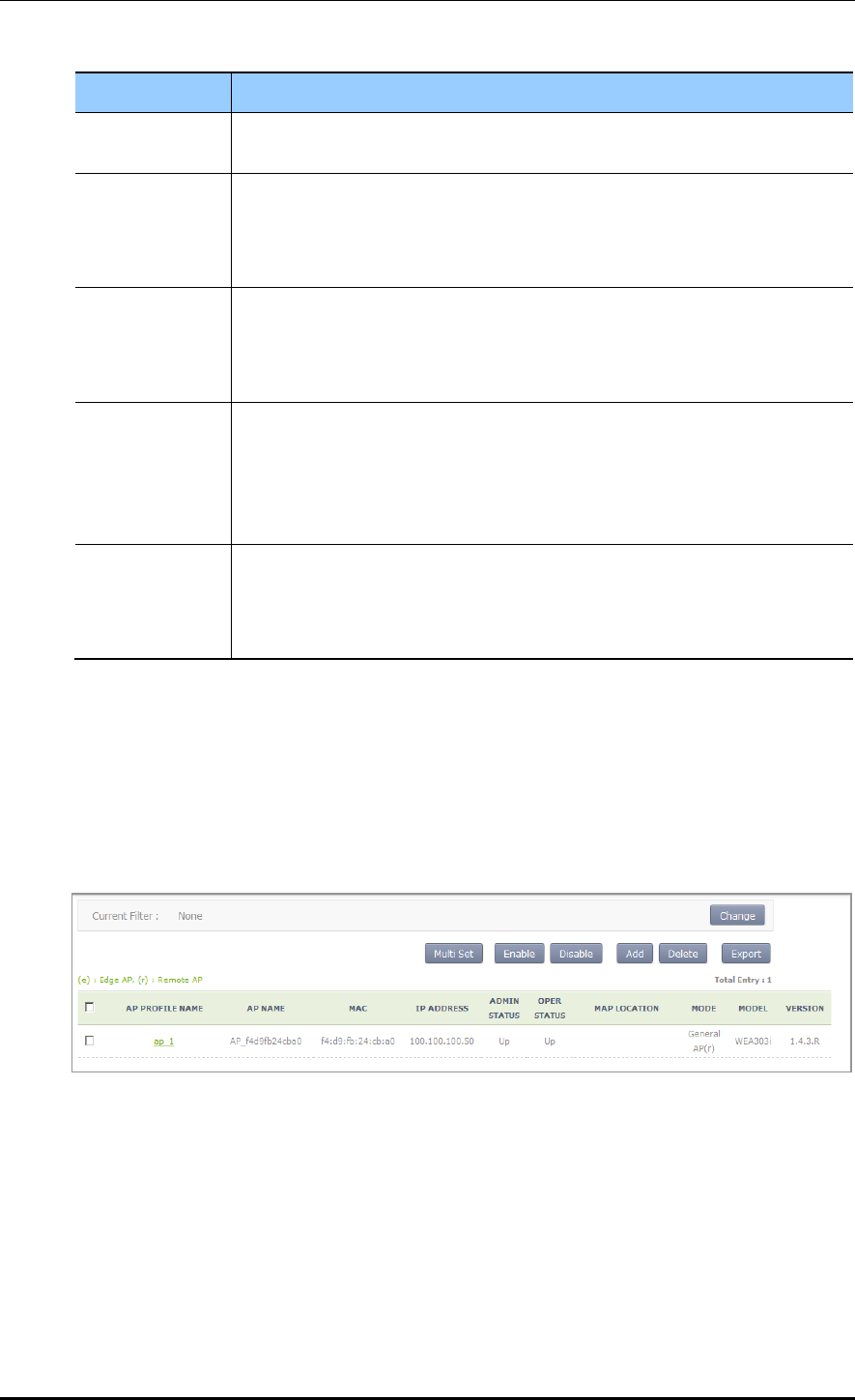
CHAPTER 4. AP Connection Management
© SAMSUNG Electronics Co., Ltd. page 149 of 628
Parameter
Description
CAPWAP protocol. It is recommended not to use a different port number if it is
specially required.
PUBLIC_IP_ADD
RESS
PUBLIC IP address of the APC to add
This address is an IP required by an AP to connect to the APC. If the APC is in
the NAT environment, you must enter an official IP configured in the NAT
instead of the private IP of APC.
PUBLIC_PORT
PUBLIC CAPWAP PORT number of the APC to add
This port number is required by an AP to connect to the APC. If the APC is
under the NAT environment, you must enter the port number configured in the
NAT instead of the actual CAPWAP port number of APC.
FALLBACK
START-END
TIME
Enter the time zone where an AP connected to the backup (secondary or
tertiary) APC can do fallback.
The input format is as follows:
Format: hh:mm-hh:mm
Example: 2:00-5:00 Fallback is available between 2pm and 5pm.
INTERVAL
Configures the interval that an AP connected to the backup (secondary or
tertiary) APC attempts fallback (second).
If a specific time is not entered, the default is 120 seconds.
The minimum is 60 seconds and the maximum is 1800 seconds.
2) In the menu bar of <WEC Main window>, select <Configuration> and then select
the <Access Points> menu in the sub-menus. Click the name of AP Profile to which
the redundancy function will be applied. After configuring the DISCOVERY TYPE of
AP to ‘APC Referal’, select the PRIMARY CONTROLLER NAME, SECONDARY
CONTROLLER NAME, and TERTIARY CONTROLLER NAME. For the WEC8500
model, the TERTIARY CONTROLLER NAME is not shown in the menu.
Figure 61. AP retrieving window

CHAPTER 4. AP Connection Management
© SAMSUNG Electronics Co., Ltd. page 150 of 628
Figure 62. AP redundancy Configuration Window
Parameter
Description
APC_NAME
Enter the name of an APC registered to redundancy.
- Primary apc: The first APC that the AP attempts to connect.
It is usually configured with the currently connected APC.
- Secondary-apc, tertiary-apc: APC that the AP attempts to
connect when there is no response from the primary-apc.
DISCOVERY_TYPE
Discovery Type
- ap-followed: Discovery type is set by AP.
- apc-referal: Discovery type is set by APC using the backup
APC lists. To apply the priority of APC to which the AP will
be connected, operator needs to select the apc-referal.
- Auto: Discovery type is automatically changed by the AP for
automatic connection to the APC.
- DHCP: Discovery type is interoperating with the DHCP
server. To use this mode, IP ADDRESS POLICY of the AP
must be set to DHCP.

CHAPTER 4. AP Connection Management
© SAMSUNG Electronics Co., Ltd. page 151 of 628
4.2 AP Management
4.2.1 AP Group Configuration
The APC manages the services provided to the AP by group. An operator can add or delete
several APs to/from a group. It is also possible to add/remove WLANs to/from an AP
group so that the same WLAN services can be provided for each group.
When the APC is installed for the first time, a ‘default’ group is created. When the AP
information is created first time, the AP is automatically added to the ‘default’ group.
If the ‘auto-discovery’ mode is enabled in the APC, an AP connected to the APC is
automatically added to the ‘default’ group. For reference, operator can specify a specific
AP group where an AP will be added during auto-discovery configuration.
An operator can manage the services per group by creating a new AP group and can move
or a specific AP to another group or delete it in the original group. The APs deleted in a
group are automatically moved to the ‘default’ group.
When a new AP group is created, it is possible to configure AP information for each group.
If the Overwrite option is enabled for each setting, the respective setting is applied to all
APs within the group.
Generally, up to 16 WLANs can be added to an AP group. However, if a root AP is
contained in an AP group, only up to 15 WLANs can be added to the group.
If the AP group information is changed, i.e. if an AP moves to another group, the AP uses
the WLAN of a new group. Therefore, some existing WLANs in the AP are deleted and
some new WLANs can be added. The detail example is shown below.
(Example) Default group: Includes wlan1, wlan2, wlan3, and wlan4.
New group: Includes wlan4, wlan5, and wlan6.
When the AP_1 moves from the default group to a new group
The APC asks the AP_1 to delete the wlan1, wlan2, and wlan3.
The APC asks the AP_1 to add the wlan5 and wlan6.
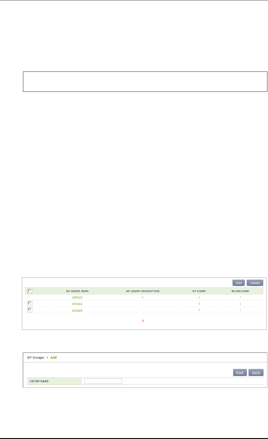
CHAPTER 4. AP Connection Management
© SAMSUNG Electronics Co., Ltd. page 152 of 628
Configuration using CLI
To manage an AP group, execute the command as follows.
1) Go to configure mode of CLI.
WEC8500# configure terminal
WEC8500/configure#
2) Create or delete an AP group. Use ‘no’ parameter in front of the command to delete an
AP group.
ap-group [AP_GROUP_NAME]
no ap-group [AP_GROUP_NAME]
3) Add or delete an AP to or from the AP group. Use ‘no’ parameter in front of the
command to delete an AP from the AP group. But, for a default AP group, you cannot
delete an AP from the group. If you delete an AP from other AP groups other than the
default group, the deleted AP is included into the default AP group.
add-ap [AP_NAME]
no add-ap [AP_NAME]
4) Use the ‘show ap-group summary’ command to check the AP group information.
Configuration using Web UI
In the menu bar of <WEC Main window>, select <Configuration> and then select the
<AP Groups> menu in the sub-menus. It provides the group configuration of the AP.
Click the <Add> or <Delete> button to add or delete a group.
Figure 63. AP groups configuration Window
Figure 64. AP Group Addition Window

CHAPTER 4. AP Connection Management
© SAMSUNG Electronics Co., Ltd. page 153 of 628
4.2.1.1 General AP Group Settings
To aid management of APs in groups, the APC allows configuration of settings which can
be applied commonly to each group. The following functions are provided:
Parameter
Description
Description
This configures the description of the AP group.
AP Mode
This configures the operation mode of the AP. The operator can select
General AP, Root AP, or Repeater AP.
Location
This configures the installation location information of the AP.
IP Mode
This configures the IP configuration mode of the AP. The operator can select
DHCP or AP Priority.
AP Status
This configures the up/down status of the AP.
Redundancy
If the APCs are configured for redundancy, this configures the discovery
type and Primary/Secondary/Tertiary Controller settings of the AP.
The APC provides the overwrite option for each AP group setting. If the Overwrite option
is enabled for each setting, the respective setting is applied to all APs within the group.
For example, if the Overwrite option is enabled for AP Mode and AP Mode is set to
General, all the APs within the group will run as General APs.
Configuration using CLI
To configure redundancy settings for the AP group, perform the following commands:
1) Go to configure mode of CLI.
WEC8500# configure terminal
WEC8500/configure#
2) Enter the AP Group configuration mode.
ap-group [AP_GROUP_NAME]
3) Enter the profile configuration mode for the AP group.
Profile
4) Configure the following AP group profiles:
description
overwrite-ap-mode
no overwrite-ap-mode
ap-mode
overwrite-location
no overwrite-location
location

CHAPTER 4. AP Connection Management
© SAMSUNG Electronics Co., Ltd. page 154 of 628
overwrite-ip-mode
no overwrite-ip-mode
ip-mode
overwrite-state
no overwrite-state
shutdown
no shutdown
no overwrite-redundancy
discovery
primary-apc
no primary-apc
secondary-apc
no secondary-apc
tertiary-apc
no tertiary-apc
Parameter
Description
DESCRIPTION
This contains a brief description of the AP group.
OVERWRITE-AP-
MODE
If overwrite-ap-mode is enabled, the AP mode information set for the
group is applied to all APs within the group.
AP-MODE
This is the AP operation mode. The following modes are available:
- generalAp: General operation mode. Default value.
- rootAp: AP mode where a repeater AP can be connected.
- repeasterAp: AP mode that is connected to a wireless area and the
APC through the root AP.
OVERWRITE-
LOCATION
If overwrite-location is enabled, the location information set for the
group is applied to all APs within the group.
LOCATION
This is the location information of the AP.
OVERWRITE-IP-MODE
If overwrite-ip is enabled, the IP mode information set for the group is
applied to all APs within the group.
IP-MODE
This is the mode of receiving an IP address by the AP. The following
modes are available:
- dhcp: The AP receives IP address allocation using DHCP.
- ap: The AP uses a manually configured IP address.
OVERWRITE-STATE
If overwrite-state is enabled, the AP state information set for the group
is applied to all APs within the group.
shutdown
This sets the AP state to UP or DOWN.
OVERWRITE-
REDUNDANCY
If overwrite-redundancy is enabled, the redundancy setting (primary-
apc, secondary-apc, tertiary-apc) of the AP group is applied to all APs
within the group.
DISCOVERY
If the APCs are configured for redundancy, this configures the method
used for APs to connect to the APC. The following modes are available:
- ap-followed: The discovery type and discovery list configured for the
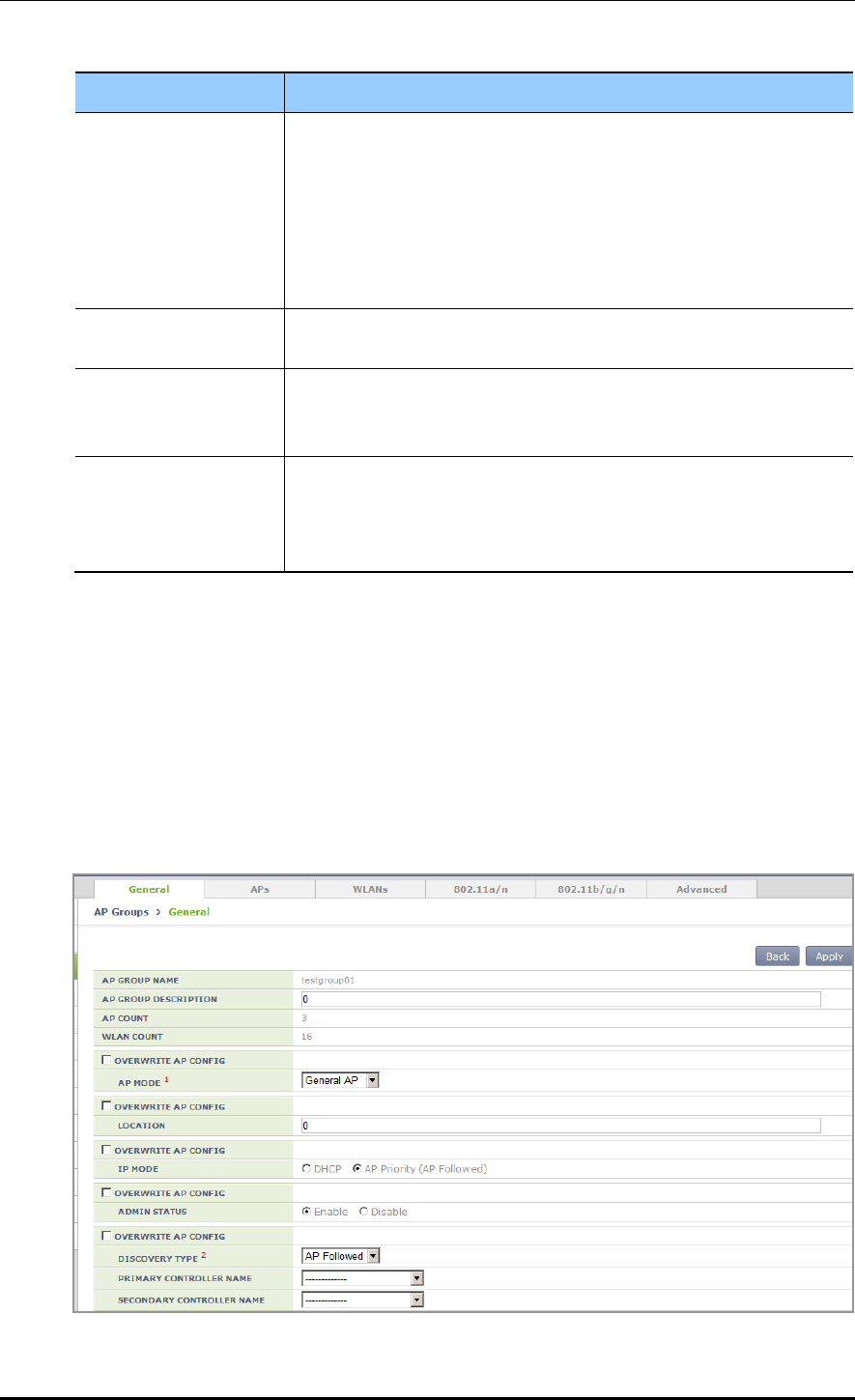
CHAPTER 4. AP Connection Management
© SAMSUNG Electronics Co., Ltd. page 155 of 628
Parameter
Description
AP are used.
- apc-referral: The APC list configured for the APC is used as the
discovery list.
- DHCP: The APC list information relayed by DHCP option 138 (IPv4)
or option 52 (IPv6) is used as the discovery list.
- auto: Discovery type is automatically changed by the AP for automatic
connection to the APC.
PRIMARY-APC
This is the name of the primary APC server. The AP attempts to
connect to this APC first.
SECONDARY-APC
This is the name of the secondary APC server. If the AP is unable to
connect to the primary APC, the AP attempts to connect to this APC on
its second connection attempt.
TERTIARY-APC
This is the name of the tertiary APC server. If the AP is unable to
connect to the secondary APC, the AP attempts to connect to this APC
on its third connection attempt. The WEC8050 model does not support
Tertiary-APC.
5) Use the ‘show ap-group detail [AP_GROUP_NAME]’ command to check the AP
group information.
Configuration using Web UI
In the menu bar of <WEC Main Window>, select <Configuration>, select <AP Groups>
in the submenu, and then select an AP group to configure. In the ‘General’ tab of the AP
group, configure the necessary settings. If the OVERWRITE AP CONFIG checkbox is
selected, the respective setting is applied to all APs within the group.
Figure 65. General Configuration Window for AP Group

CHAPTER 4. AP Connection Management
© SAMSUNG Electronics Co., Ltd. page 156 of 628
4.2.1.2 Adding/Removing APs
To aid management of APs in groups, the APC allows addition/removal of APs to/from AP
groups.
Configuration using CLI
1) Go to configure mode of CLI.
WEC8500# configure terminal
WEC8500/configure#
2) Create an AP group or enter the AP group configuration mode.
ap-group [AP_GROUP_NAME]
3) Add/remove an AP to/from the AP group. Use ‘no’ parameter in front of the command
to delete an AP from the AP group. However, you cannot delete an AP from a default
AP group. If you delete an AP from groups other than the default group, the deleted AP
is then included in the default AP group.
add-ap [AP_NAME]
no add-ap [AP_NAME]
4) Use the ‘show ap-group summary’ command to check the AP group information.
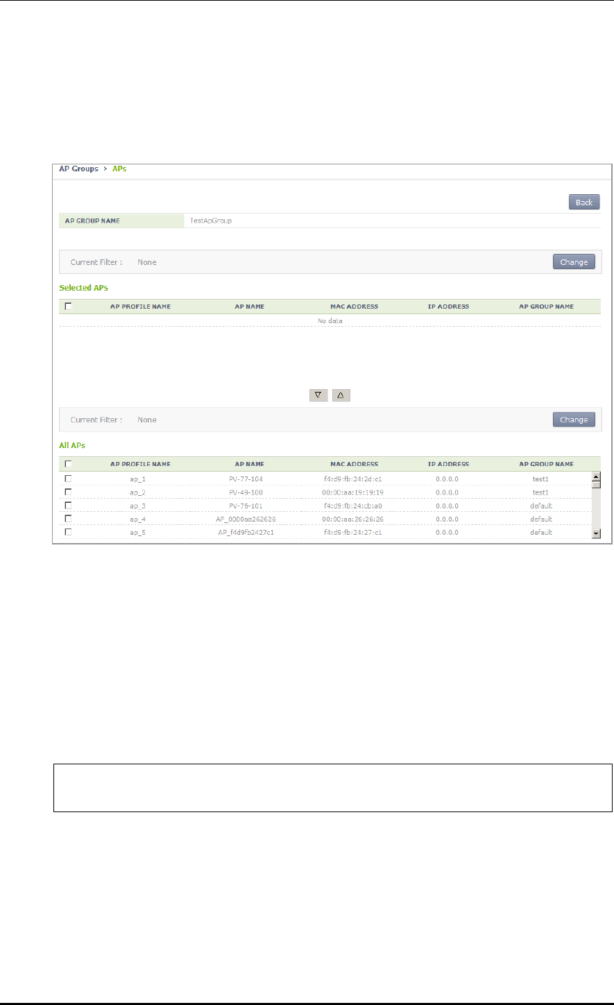
CHAPTER 4. AP Connection Management
© SAMSUNG Electronics Co., Ltd. page 157 of 628
Configuration using Web UI
In the menu bar of <WEC Main Window>, select <Configuration>, select <AP Groups>
in the submenu, and then select an AP group to configure. Under the ‘APs’ tab of the AP
group, APs can be added or removed.
Figure 66. AP Add/Remove Window for AP Group
4.2.1.3 Adding/Removing WLANs
To allows the same WLAN services to be provided to the APs allocated to each group, the
APC allows addition/removal of WLANs to/from each AP group.
Configuration using CLI
1) Go to configure mode of CLI.
WEC8500# configure terminal
WEC8500/configure#
2) Create an AP group or enter the AP group configuration mode.
ap-group [AP_GROUP_NAME]
3) Add/remove an WLAN to/from the AP group. Use ‘no’ parameter in front of the
command to delete an WLAN from the AP group.
add-wlan [WLAN_ID]
no add-wlan [WLAN_ID]
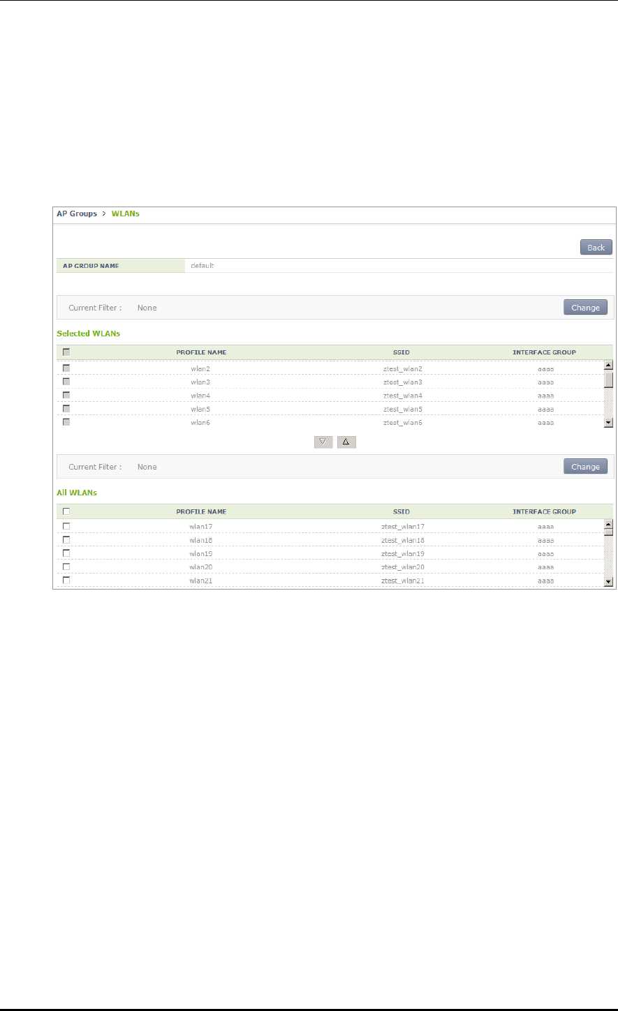
CHAPTER 4. AP Connection Management
© SAMSUNG Electronics Co., Ltd. page 158 of 628
4) Use the ‘show ap-group summary’ command to check the AP group information.
Configuration using Web UI
In the menu bar of <WEC Main Window>, select <Configuration>, select <AP Groups>
in the submenu, and then select an AP group to configure. Under the ‘WLANs’ tab of the
AP group, WLANs can be added or removed.
Figure 67. WLAN Add/Remove Window for AP Group
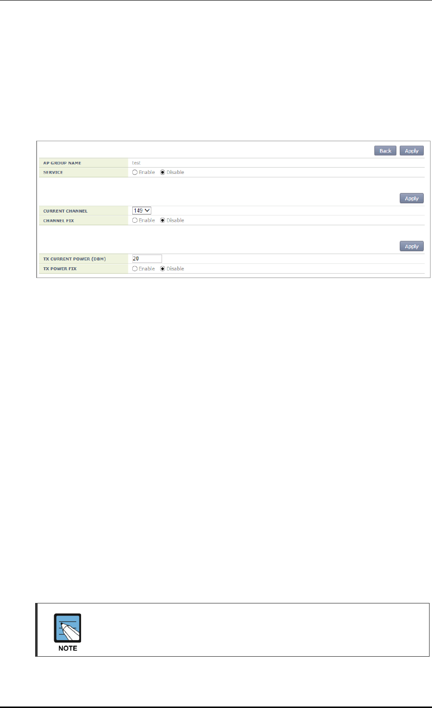
CHAPTER 4. AP Connection Management
© SAMSUNG Electronics Co., Ltd. page 159 of 628
4.2.1.4 802.11a/n Configuration
Configuration using Web UI
In the menu bar of <WEC Main Window>, select <Configuration>, select <AP Groups>
in the submenu, and then select an AP group to configure. Settings can be configured under
the ‘802.11a/n’ tab of the AP group.
Figure 68. 802.11a/n Window for AP Group
The configuration items are as follows:
[Service Configuration of AP Group]
SERVICE: Enable or disable the radio service.
[Channel Configuration]
CURRENT CHANNEL: Channel configuration (range: 36-165)
CHANNEL FIX: The configured channel is configured as fixed and it is not affected
by automatic adjustment functions such as RRM. When the <Monitor> <Access
Points> <Radio> <802.11a/n/ac> menu is selected, the channel value is shown
as * (optional).
[TX Power Setting]
TX CURRENT POWER: TX power (range: 3-23)
TX POWER FIX: The configured TX power is configured as fixed and it is not
affected by automatic adjustment functions such as RRM. When the <Monitor>
<Access Points> <Radio> <802.11a/n/ac> menu is selected, the TxPower value
is shown as * (optional).
To check the configured channel and TX power information, go to <Monitor>
<Access Points> <Radio> <802.11a/n/ac>.
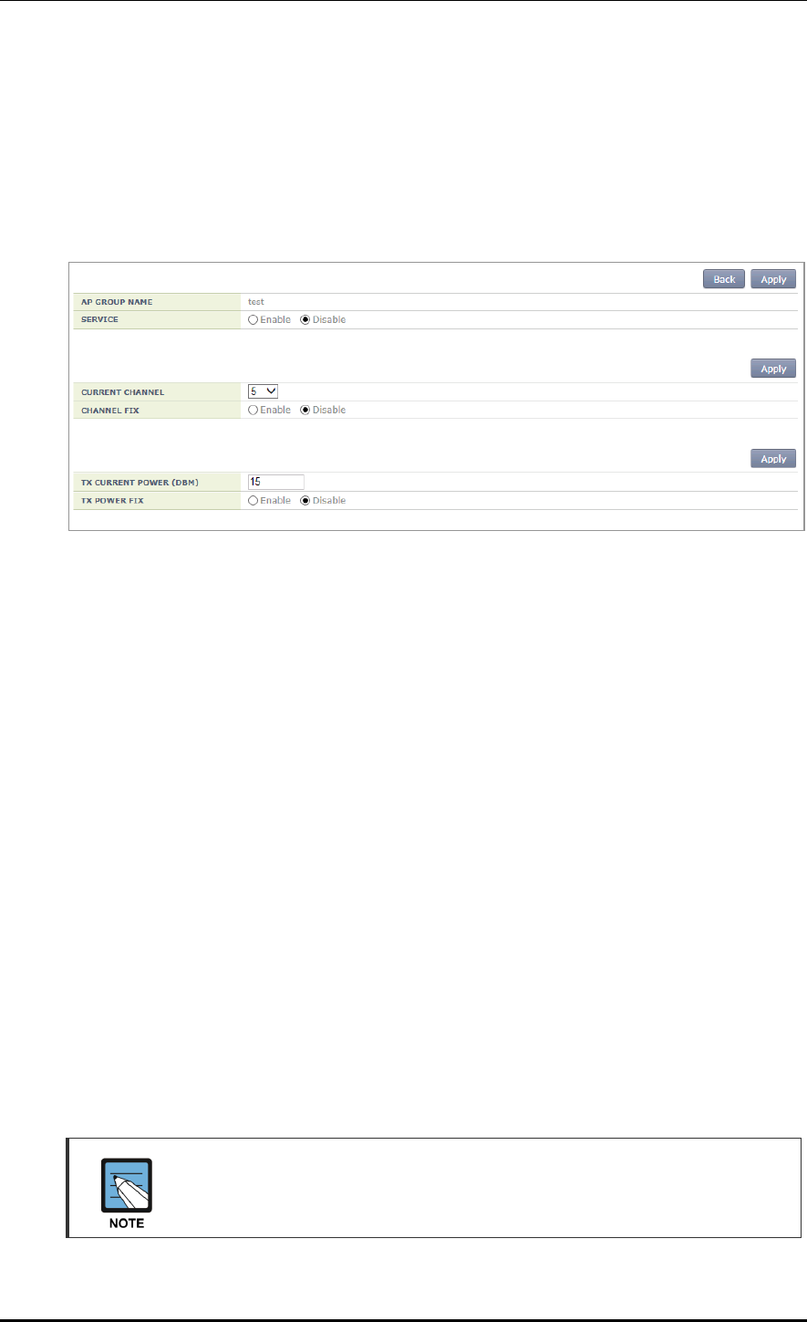
CHAPTER 4. AP Connection Management
© SAMSUNG Electronics Co., Ltd. page 160 of 628
4.2.1.5 802.11b/g/n Configuration
Configuration using Web UI
In the menu bar of <WEC Main Window>, select <Configuration>, select <AP Groups>
in the submenu, and then select an AP group to configure. Settings can be configured under
the ‘802.11b/g/n’ tab of the AP group.
Figure 69. 802.11b/g/n Window for AP Group
The configuration items are as follows:
[Service Configuration of AP Group]
SERVICE: Enable or disable the radio service.
[Channel Configuration]
CURRENT CHANNEL: Channel configuration (range: 1-14)
CHANNEL FIX: The configured channel is configured as fixed and it is not affected
by automatic adjustment functions such as RRM. When the <Monitor> <Access
Points> <Radio> <802.11b/g/n> menu is selected, the channel value is shown
as * (optional).
[TX Power Setting]
TX CURRENT POWER: TX power (range: 3-23)
TX POWER FIX: The configured TX power is configured as fixed and it is not
affected by automatic adjustment functions such as RRM. When the <Monitor>
<Access Points> <Radio> <802.11b/g/n> menu is selected, the TxPower value
is shown as * (optional).
To check the configured channel and TX power information, go to <Monitor>
<Access Points> <Radio> <802.11b/g/n>.

CHAPTER 4. AP Connection Management
© SAMSUNG Electronics Co., Ltd. page 161 of 628
4.2.1.6 Advanced Configuration
In order to provide the same services to the APs allocated to each group, the APC allows
configuration of advanced settings for each AP group.
Configuring AP Group Profile with CLI
1) Go to configure mode of CLI.
WEC8500# configure terminal
WEC8500/configure#
2) Create an AP group or enter the AP group configuration mode.
ap-group [AP_GROUP_NAME]
3) Enter the profile configuration mode for the AP group.
profile
4) Configure the following AP group profiles:
overwrite-apc-ap-timer
no overwrite-apc-ap-timer
echo-interval
discovery-interval
report-interval
statistics-timer
retransmit-interval
echo-retransmit-interval
max-echo-retransmit
overwrite-telnet-ssh
no overwrite-telnet-ssh
telnet-enable
no telnet-enable
ssh-enable
no ssh-enable
overwrite-console
no overwrite-console
console-enable
no console-enable
overwrite-dtls
no overwrite-dtls
dtls-policy
overwrite-led-control
no overwrite-led-control
led-config

CHAPTER 4. AP Connection Management
© SAMSUNG Electronics Co., Ltd. page 162 of 628
overwrite-vlan
no overwrite-vlan
vlan-support
no vlan-support
native-vlanId
no native-vlanId
overwrite-poe-type
no overwrite-poe-type
overwrite-uplink-bandwidth
no overwrite-uplink-bandwidth
uplink-bandwidth
overwrite-temperature-alarm
no overwrite-temperature-alarm
temperature-alarm-on-level
temperature-alarm-off-level
temperature-alarm-control-type
overwrite-link-aggregation
no overwrite-link-aggregation
link-aggregation
no link-aggregation
Parameter
Description
DESCRIPTION
This contains a brief description of the AP group.
OVERWRITE-APC-AP-TIMER
If overwrite-apc-ap-timer is enabled, the APC-AP timer setting of
the group is applied to all APs within the group.
ECHO-INTERvAL
Configures the time when an echo request message is
transmitted to the APC where an AP joins (unit: seconds).
DISCOVERY-INTERVAL
Configures a waiting time until the CAPWAP discovery response
message is received (unit: seconds).
REPORT-INTERVAL
Configures the time interval for transmitting the description error
from AP to the APC (unit: seconds).
STATISTICS-TIMER
Configures the time interval for transmitting the statistical
information provided by the CAPWAP (unit: seconds).
RETRANSMIT-INTERVAL
The APC waits for this length of time before retransmitting an
echo request message when there is no response. The APC sets
double the length of echo-interval as the echo timeout time. If no
echo message is received from the AP for as long as double the
length of the echo-interval, the APC judges that the AP is down
(unit: seconds).
MAX-ECHO-RETRANSMIT
The APC waits for this length of time before retransmitting an
echo request message when there is no response. The APC sets

CHAPTER 4. AP Connection Management
© SAMSUNG Electronics Co., Ltd. page 163 of 628
Parameter
Description
double the length of echo-interval as the echo timeout time. If no
echo message is received from the AP for as long as double the
length of the echo-interval, the APC judges that the AP is down
(unit: seconds).
OVERWRITE-TELNET-SSH
If overwrite-telnet-ssh is enabled, the telnet and SSH settings for
the AP group are applied to all APs within the group.
TELNET-ENABLE
This enables the telnet server and configures telnet port of the
AP.
SSH-ENABLE
This enables the SSH server and configures SSH port of the AP.
OVERWRITE-CONSOLE
If overwrite-console is enabled, the telnet and SSH settings of
the AP group are applied to all APs within the group.
CONSOLE-ENABLE
This configures whether to allow console access to the AP.
OVERWRITE-DTLS
If overwrite-dtls is enabled, the DTLS settings of the AP group
are applied to all APs within the group.
DTLS-POLICY
Configures the DTLS Policy of an AP.
OVERWRITE-LED-CONTROL
If overwrite-led-control is enabled, the LED settings of the AP
group are applied to all APs within the group.
LED-CONFIG
This configures whether to turn the LED on/off.
OVERWRITE-VLAN
If overwrite-vlan is enabled, the VLAN settings of the AP group
are applied to all APs within the group.
VLAN-SUPPORT
This configures whether to enable the native VLAN of the AP.
NATIVE-VLANID
This configures the native VLAN value of the AP.
OVERWRITE-POE-TYPE
If the overwrite-poe-type is activated, the POE Type information
set in the AP group is applied to all APs in the group.
POE-TYPE
Sets the POE Type information below.
802.3at/802.3af/auto
OVERWRITE-UPLINK-
BANDWIDTH
If the overwrite-uplink-bandwidth is activated, the uplink
bandwidth information set in the AP group is applied to all APs in
the group.
UPLINK-BANDWIDTH
Sets the allowed value for AP uplink bandwidth.
Possible to set between 1 and 1024 Mbps and if it is set to 0, the
uplink bandwidth is not restricted.
OVERWRITE-
TEMPERATURE-ALARM
If the overwrite-temperature-alarm is activated, the temperature
alarm information set in the AP group is applied to all APs in the
group.
TEMPERATURE-ALARM-ON-
LEVEL
If the temperature of the AP exceeds the Temperature-Alarm-On-
Level, the temperature alarm occurs.
The default is 98 and possible to set between 50 and 130.
TEMPERATURE-ALARM-
OFF-LEVEL
If the temperature of the AP is less than the Temperature-Alarm-
Off-Level, the temperature alarm is cleared.
The default is 90 and possible to set between 50 and 130.

CHAPTER 4. AP Connection Management
© SAMSUNG Electronics Co., Ltd. page 164 of 628
Parameter
Description
TEMPERATURE-ALARM-
CONTROL-TYPE
If the temperature alarm occurs, whether the radio of the AP is
set to be off or on.
OVERWRITE-LINK-
AGGREGATION
If the overwrite-link-aggregation is activated, the link aggregation
information set in the AP group is applied to all APs in the group.
LINK-AGGREGATION
In case of an AP model for 802.11ac, provide two uplink Ethernet
ports.
Possible to set link aggregation for two Ethernet ports.
If link aggregation is activated, possible to set the following
mode:
- Both (Destination + Source)
- Destination
- Source
5) Use the ‘show ap-group detail [AP_GROUP_NAME]’ command to check the AP
group information.
Configuring AirMove Service of AP Group with CLI
1) Go to configure mode of CLI.
WEC8500# configure terminal
WEC8500/configure#
2) Create an AP group or enter the AP group configuration mode.
ap-group [AP_GROUP_NAME]
3) Enter the profile configuration mode for the AP group.
profile
4) Configure the AirMove service of the AP group.
enable: Enables/disables the AirMove service.
target-ap: This option is used for selecting APs which will be applied with the
changes made to the group settings. If 'all' is selected, changes are applied to all APs
and config priority of the APs also change to group. If 'keep-ap-config' is selected,
only the APs whose config priority is set to group have the airmove value of the
group applied to them.
WEC8500# configure terminal
WEC8500/configure# ap-group default
GroupName : default
WEC8500/configure/ap-group default# airmove
WEC8500/configure/ap-group default/airmove# ?
decision-delta Set delta value for handover decision
enable Airmove enable
exit Exit from airmove mode

CHAPTER 4. AP Connection Management
© SAMSUNG Electronics Co., Ltd. page 165 of 628
number-of-channel Set the number of channel required during
one time scanning
number-of-proreq Set the number of probe request required
during one time scanning
scan-time-channel Set time required for one channel scanning
scan-time-interleave Set interval time required for new scanning
start
scan-time-service Set time required for STA service during
STA’s scanning
scan-trigger-level Set a trigger level for STA's scanning
start
target-ap Set config target ap
<cr>
WEC8500/configure/ap-group default/airmove# enable ?
<cr>
WEC8500/configure/ap-group default/airmove# decision-delta ?
1 - 100 Enter the value [dBm]
WEC8500/configure/ap-group default/airmove# number-of-channel ?
1 - 20 Enter the number
WEC8500/configure/ap-group default/airmove# number-of-proreq ?
1 - 10 Enter the number
WEC8500/configure/ap-group default/airmove# scan-time-channel ?
0 - 100 Enter the time [ms]
WEC8500/configure/ap-group default/airmove# scan-time-interleave ?
1000 - 10000 Enter the time [ms]
WEC8500/configure/ap-group default/airmove# scan-time-service ?
1 - 1000 Enter the time [ms]
WEC8500/configure/ap-group default/airmove# scan-trigger-level ?
-128 - 0 Enter the trigger level [dBm]
WEC8500/configure/ap-group default/airmove# target-ap ?
all All
keep-ap-config Keep ap config
WEC8500/configure/ap-group default/airmove# end
4) Use the ‘show airmove group [ap_group_name]’ command to check the AP group
information.
WEC8500# show airmove group default
Airmove Group Configurations
----------------------------
Airmove State Disable
Target AP Keep Ap Config
Scan trigger level -70 dBm
Scanning time for one channel 5 ms
Service time during scanning 100 ms
Scanning interval time 1000 ms
Number of probe requests 2
Number of scanning channels 4
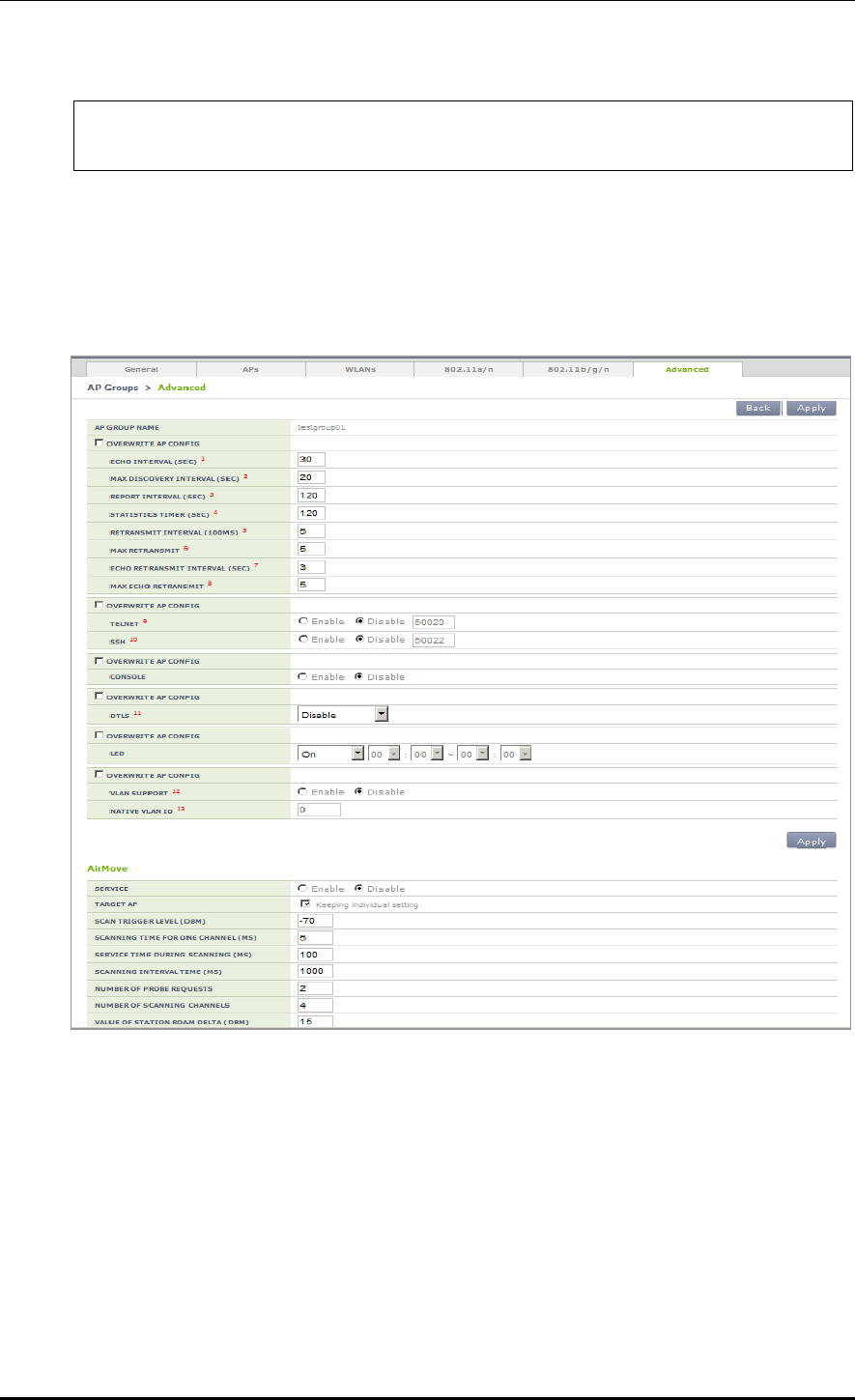
CHAPTER 4. AP Connection Management
© SAMSUNG Electronics Co., Ltd. page 166 of 628
Value of station roam delta 15
WEC8500#
Configuration using Web UI
In the menu bar of <WEC Main Window>, select <Configuration>, select <AP Groups>
in the submenu, and then select an AP group to configure. Advanced settings and AirMove
settings of the AP group can be changed under the ‘Advanced’ tab of AP Group.
Figure 70. Advanced Configuration Window for AP Group

CHAPTER 4. AP Connection Management
© SAMSUNG Electronics Co., Ltd. page 167 of 628
4.2.2 Configuring Remote AP Group
If the APs are located in an area where the APC is not located, those APs must be classified
into a separate group for service. The APC can manage the APs in another area by grouping
them into a remote AP group.
In the Remote AP group, the operator can configure the below information and the APs in
the Remote AP group are operating based on the same configuration.
Addition/Deletion of Remote AP
Possible to add or delete APs to be included in the remote AP group.
Local Authentication
Radius Server
Possible to set a Radius server which will authenticate a station connecting to the
remote AP.
Remote AP User List
Possible to add or delete a user (station) to be managed in the remote AP.
Role Based Access Control
Possible to apply the ACL profile.
Tunnel Forwarding
Possible to add the split tunnel ACL settings of the WLAN set with the tunneling
mode.
Local Bridging Forwarding
Possible to add settings of VLAN ID, ACL, and Pre-Auth ACL of the WLAN set
with the local bridging mode.
When an AP group is added and the remote AP group is checked, APs included in the AP
group operates in the remote AP mode.
If an AP is added to or deleted from a remote AP group, the AP is rebooted and reconnected
to the APC. If an AP moves between remote AP groups, the AP is not rebooted.
4.2.2.1 Addition/Removal Setting
Configuration using CLI
1) Go to configure mode of CLI.
WEC8500# configure terminal
WEC8500/configure#
2) Create an AP group.
ap-group[REMOTE_AP_GROUP_NAME]
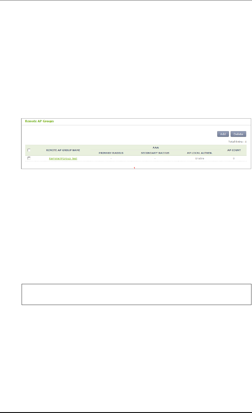
CHAPTER 4. AP Connection Management
© SAMSUNG Electronics Co., Ltd. page 168 of 628
3) Designate remote AP group properties to the AP group.
group-type remote
4) When the remote AP group is deleted, use the 'no' parameter in front of the ap-group
command to delete the remote AP group.
no ap-group[REMOTE_AP_GROUP_NAME]
Configuration using Web UI
In the menu bar of <WEC Main Window>, select <Configuration> and then select the
<AP Groups> menu in the sub-menus. Click the <Add> or <Delete> button to add or
delete a group.
Figure 71. Remote AP Group Add/Remove Window
4.2.2.2 Local Authentication Configuration for Remote AP Group
Users (stations) accessing the remote AP and the Radius server which authenticates such
users can be configured.
Configuration using CLI
To configure the local authentication of the remote AP group, perform the command as
follows:
1) Go to configure Remote AP Group configuration mode of CLI.
WEC8500# configure terminal
WEC8500/configure#
WEC8500/configure/ap-group {remote-ap-group-name}
WEC8500/configure/ap-group/{remote-ap-group-name}#remote
2) Configure Primary Radius Server 1, Primary Radius Server 2, and Primary Radius
Server 3. The RADIUS server information must be created in the radius of the security
item in advance. To delete the configured RADIUS server information, enter ‘no’
parameter in front of the command.
remote primary-radius[RADIUS_SERVER_INDEX]
no remote primary-radius[RADIUS_SERVER_INDEX]
remote secondary-radius[RADIUS_SERVER_INDEX]
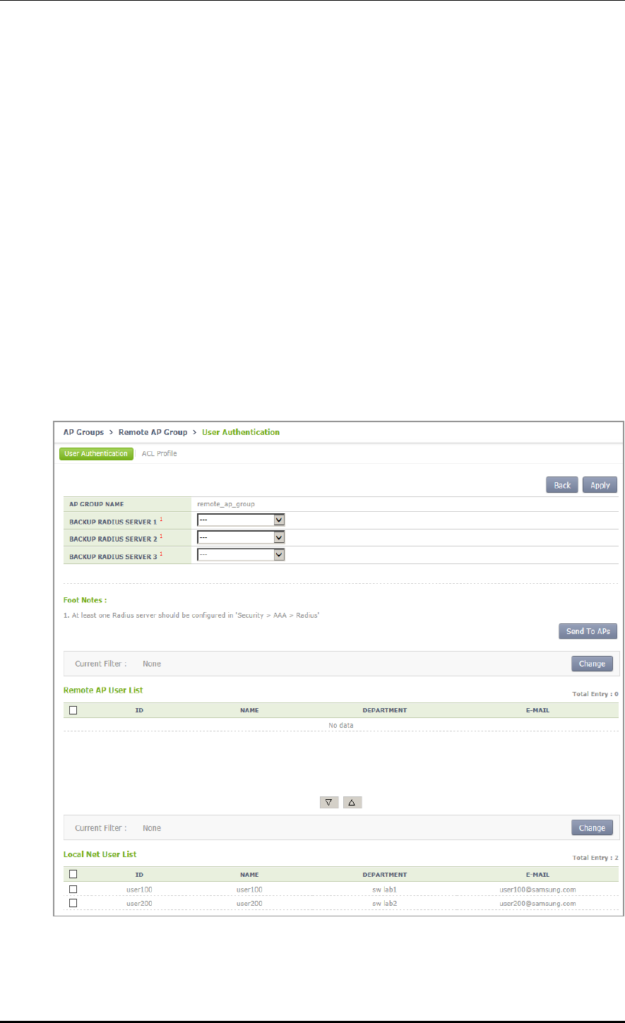
CHAPTER 4. AP Connection Management
© SAMSUNG Electronics Co., Ltd. page 169 of 628
no remote secondary-radius[RADIUS_SERVER_INDEX]
remote tertiary-radius[RADIUS_SERVER_INDEX]
no remote tertiary-radius[RADIUS_SERVER_INDEX]
3) Add or delete users (stations) connecting to the remote AP.
add-user [USER NAME]
no add-user [USER NAME]
4) Execute the ‘show remote-ap-group detail [REMOTE AP GROUP NAME]’
command to check the AP group information.
Configuration using Web UI
In the menu bar of <WEC Main window>, select <Configuration> and then select the
<AP Groups> menu in the sub-menus. After selecting the name of a remote AP group,
configure a Radius server or add or delete users in "User Authentication" item of the
‘Remote AP Group’ tab.
Figure 72. Local Authentication Configuration Window for Remote AP Group

CHAPTER 4. AP Connection Management
© SAMSUNG Electronics Co., Ltd. page 170 of 628
4.2.2.3 Role-based Access Control Configuration of Remote AP Group
Explanation on the configuration of the role based access control of the remote AP group is
separately made in the “Role Based Access Control” chapter.
4.2.2.4 Configuring Tunneling Forwarding of Remote AP Group
Possible to configure the split ACL to a WLAN set with tunneling among WLANs included
in the remote AP group.
Configuration using CLI
To configure the split ACL of the remote AP group, perform the command as follows:
1) Go to configure Remote AP Group configuration mode of CLI.
WEC8500# configure terminal
WEC8500/configure#
WEC8500/configure/ap-group [remote-ap-group-name]
WEC8500/configure/ap-group/[remote-ap-group-name]#remote
2) Designate the split ACL in the WLAN set with the tunneling mode.
tunneling-forwarding [WLAN-ID] [SPLIT-ACL-NAME]
3) Execute the ‘show ap-group remote-forwarding [REMOTE AP GROUP NAME] ’
command to check the AP group information.
4) Use the ‘send-remote-acl-to-ap profile-only’ command to send the ACL Profile
information of the remote AP group to APs.
5) Use the ‘send-remote-acl-to-ap all’ command to send the information on the ACL
Profile, Tunneling Forwarding and Local Bridging Forwarding of the remote AP group
to APs.
Configuration using Web UI
In the menu bar of <WEC Main window>, select <Configuration> and then select the
<AP Groups> menu in the sub-menus. After selecting the name of the remote AP group,
you can configure Tunneling Forwarding in the “ACL Profile” item of the 'Remote AP
Group' tab. In addition, you can click the “Send To APs” button to send the information on
ACL Profile, Tunnel Forwarding, and Local Bridging Forwarding to APs.
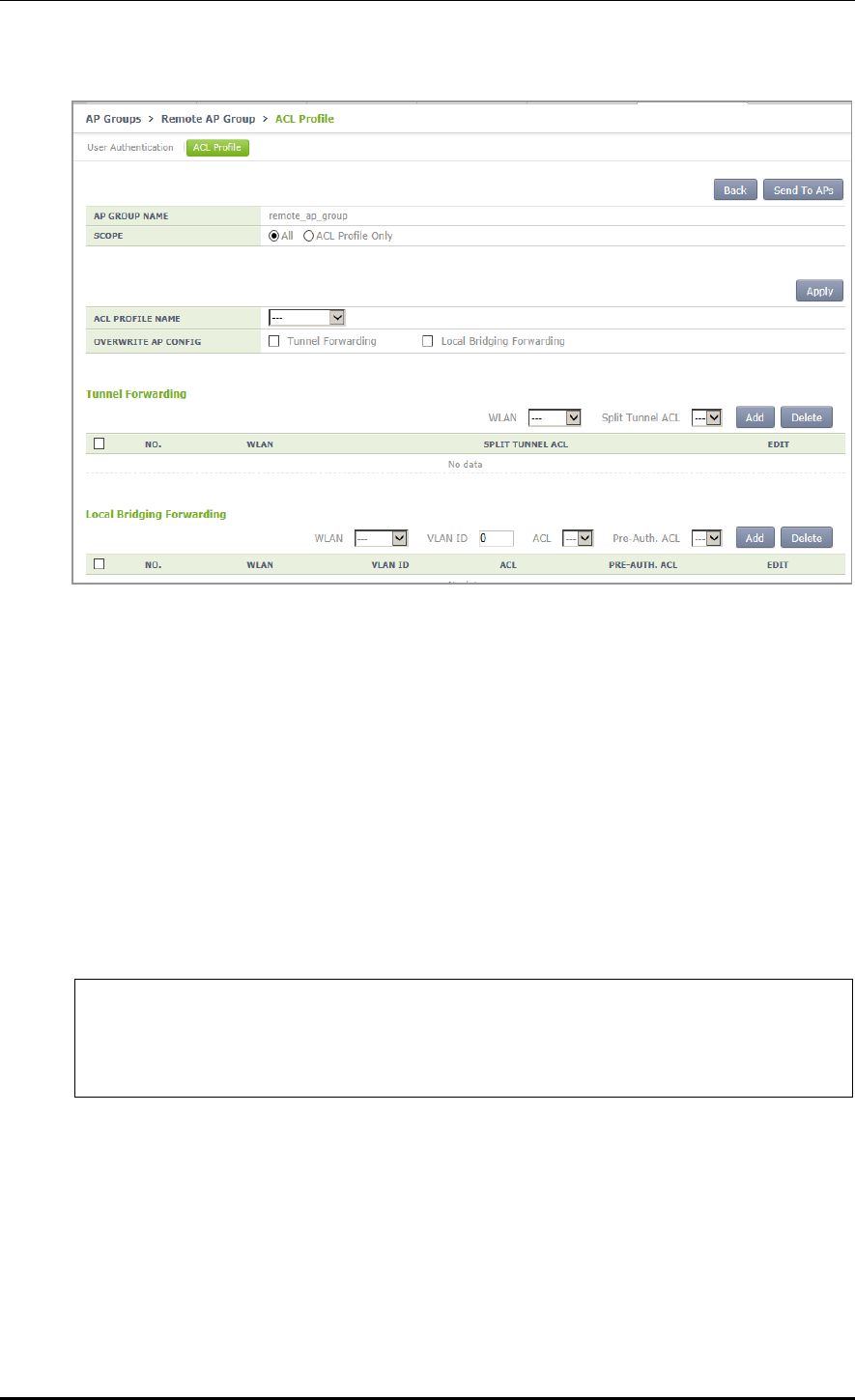
CHAPTER 4. AP Connection Management
© SAMSUNG Electronics Co., Ltd. page 171 of 628
Figure 73. Window for Configuring Tunneling Forwarding of Remote AP Group
4.2.2.5 Configuring Local Bridging Forwarding of Remote AP Group
You can configure the VLAN ID, ACL, and PreAuth ACL to a WLAN set with local
bridging among WLANs included in the remote AP group.
Configuration using CLI
To configure the local bridging forwarding of the remote AP group, perform the command
as follows:
1) Go to configure Remote AP Group configuration mode of CLI.
WEC8500# configure terminal
WEC8500/configure#
WEC8500/configure/ap-group [remote-ap-group-name]
WEC8500/configure/ap-group/[remote-ap-group-name]#remote
2) Configure the information on Local Bridging to the WLAN set with the tunneling
mode.
local-bridging [WLAN-ID] { vlan-id [VLAN-ID] | acl-name [ACL-NAME] | pre-
auth-name [PRE-AUTH-NAME] }
3) Execute the ‘show ap-group remote-forwarding [REMOTE AP GROUP NAME]’
command to check the AP group information.
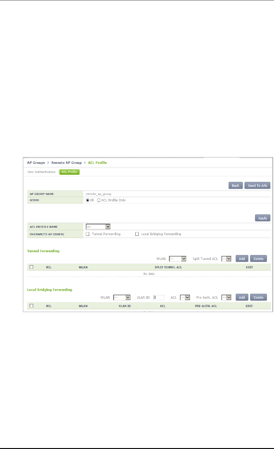
CHAPTER 4. AP Connection Management
© SAMSUNG Electronics Co., Ltd. page 172 of 628
4) Use the ‘send-remote-acl-to-ap profile-only’ command to send the ACL Profile
information of the remote AP group to APs.
5) Use the ‘send-remote-acl-to-ap all’ command to send the information on the ACL
Profile, Tunneling Forwarding and Local Bridging Forwarding of the remote AP group
to APs.
Configuration using Web UI
In the menu bar of <WEC Main window>, select <Configuration> and then select the
<AP Groups> menu in the sub-menus. After selecting the name of the remote AP group,
you can configure Local Bridging in the “ACL Profile” item of the 'Remote AP Group' tab.
In addition, you can click the “Send To APs” button to send the information on ACL Profile,
Tunnel Forwarding, and Local Bridging Forwarding to APs.
Figure 74. Window for Configuring Local Bridging Forwarding of Remote AP Group

CHAPTER 4. AP Connection Management
© SAMSUNG Electronics Co., Ltd. page 173 of 628
4.2.3 AP Time Synchronization per Group
The AP can configure its time information using either the time stamp method or the NTP
method.
In the Time Stamp type, the APC periodically transmits the time of APC to an AP and the
AP is operating based on the received time. Unless a user changes the configuration, the
default is Time Stamp type and the interval is set to 7200 seconds (2 hours).
In the NTP type, the NTP server information is transmitted to an AP and the AP
synchronizes the time with the NTP server. A NTP server list must be created to transmit
the NTP server information to an AP and maximum 10 lists can be added. The ntp-interval
(2^N) is the interval when an AP receives the time information from the NTP server.
For example, if the ntp-interval is set to 6, an AP receives the time information from the
NTP server at every 2^6, i.e. 128 seconds.
The APC provides a function for configuring the time configuration method of the AP.
Configuring Time Stamp type using CLI
1) Go to configure apc ap-time-config configuration mode of CLI.
WEC8500# configure terminal
WEC8500/configure# apc
WEC8500/configure/apc# ap-time-config
WEC8500/configure/apc/ap-time-config#
2) Configure how to transmit the time information to an AP using ‘ac-stamp’ and
configure the interval.
mode ac-stamp
ac-stamp-interval [INTERVAL]
3) To check the information, execute the ‘show apc ap-time-config’ command.
Configuring NTP type using CLI
1) Go to configure apc ap-time-config configuration mode of CLI.
WEC8500# configure terminal
WEC8500/configure# apc
WEC8500/configure/apc# ap-time-config
WEC8500/configure/apc/ap-time-config#
2) Add the NTP server information to transmit to an AP. Maximum 10 NTP server
information can be added. To delete the configured NTP server information, enter ‘no’
parameter in front of the command
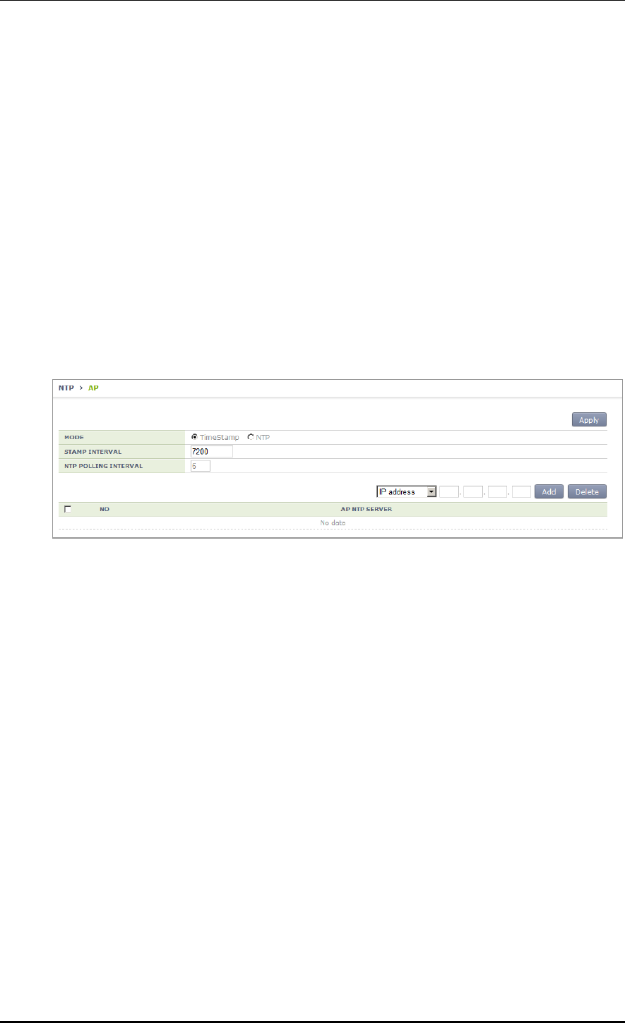
CHAPTER 4. AP Connection Management
© SAMSUNG Electronics Co., Ltd. page 174 of 628
add-ntp [NTP_SERVER_ADDRESS]
no add-ntp [NTP_SERVER_ADDRESS]
ntp-interval [NUMBER]
3) Configure the method of transmitting the time information to an AP as ‘ntp’.
mode ntp
4) Use the ‘show apc ap-time-config’ command to check the configured information.
Configuration using Web UI
In the menu bar of <WEC Main Window>, select <Configuration>, select <NTP> in the
submenu, and then select a time setting mode of the AP (TimeStamp or NTP), timestamp
interval, and NTP polling interval. Also, you can add/remove NTP server from which to
fetch time access information for the AP.
Figure 75. AP Time Synchronization Configuration Options
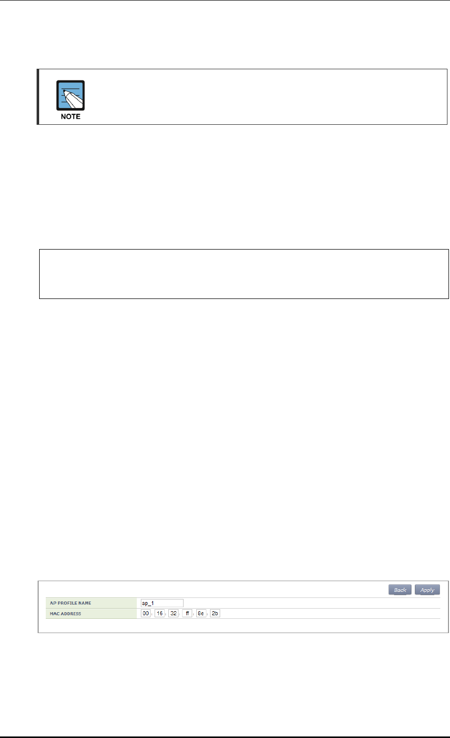
CHAPTER 4. AP Connection Management
© SAMSUNG Electronics Co., Ltd. page 175 of 628
4.2.4 AP Configuration
The management interface of APC must be configured for the connection
between APC and W-EP AP.
4.2.4.1 Configuring MAC address
Configuration using CLI
To configure AP information, execute the command as follows:
1) Go to configure AP configuration mode of CLI.
WEC8500# configure terminal
WEC8500/configure# ap [ap profile name]
WEC8500/configure/ap ap_1#
If there exists the same AP when entering [ap profile name], you are guided to the
mode where operator can configure the AP. If there is no same AP, the new AP
information is created.
2) Register the MAC address of the AP.
profile mac [MAC_ADDRESS]
3) To check the information of a configured AP, use the ‘show ap summary config’
command.
Configuration using Web UI
In the menu bar of <WEC Main window>, select <Configuration> and then select the
<Access Points> menu in the sub-menus.
1) Click the <Add> button.
2) Set AP PROFILE NAME and MAC ADDRESS and click the <Apply> button.
Figure 76. Adding Access Points

CHAPTER 4. AP Connection Management
© SAMSUNG Electronics Co., Ltd. page 176 of 628
4.2.4.2 Configuring AP Profile
Configuration using CLI
To configure an AP profile configuration, execute the command as follows:
1) Go to configure AP configuration AP profile mode of CLI.
WEC8500# configure terminal
WEC8500/configure# ap ap_1
WEC8500/configure/ap ap_1# profile
WEC8500/configure/ap ap_1/profile#
2) Configure the profile of an AP using the below command.
name [STRING]: Configures the name of an AP. If it is not entered, the ‘AP_’ +
‘MAC address’ is used as a name.
E.g. MAC address: f4:d9:fb:24:cb:a0
AP name: AP_f4d9fb24cba0
ap-mode [generalAp/rootAp/repeaterAp/snifferAp]: Configures the AP operation
mode.
ap-stats-history-enable: Configures whether to enable the AP statistics history.
client-ip [IP_ADDRESS]: Configures the client IP address, if the AP operation
mode is set to Sniffer AP.
console-enable: This configures whether to allow console access to the AP.
discovery [ap-followed/apc-referal/multicast/broadcast/DHCP]: Configures the
discovery type of an AP to find APC.
ap-followed: Finds the APC using the discovery type and discovery list
configured in an AP.
apc-referal: Uses the APC list information configured in an APC as the discovery
list
DHCP: Uses the APC list information that is received through DHCP option 138
(IPv4) or option 52 (IPv6) as the discovery list.
auto: Discovery type is automatically changed by the AP for automatic
connection to the APC.
discovery-interval [INTERVAL]: Configures the time waiting for a CAPWAP
discovery response message (unit: seconds)
dtls-policy: Configures the DTLS Policy of an AP.
echo-interval [INTERVAL]: Configures the time when an AP transmits an echo
request to the joined APC (Unit: seconds)
echo-retransmit-interval [INTERVAL]: Waiting time to retransmit an echo request
message if there is no reply. The APC configures the echo timeout as much as two
times of echo-interval. If the APC cannot receive an echo message from an AP until
two times of echo-interval is elapsed, the APC assumes that the AP is down (Unit:
seconds)

CHAPTER 4. AP Connection Management
© SAMSUNG Electronics Co., Ltd. page 177 of 628
edge-ap: Configures whether to enable the Edge AP function.
edge-ap-opmode: Smart Handover is enabled as operation mode of the edge AP.
In RSSI mode, handover is determined by looking up the RSSI value. In Force
mode, handover is performed by force.
edge-ap-threshold: Configures a threshold value for performing smart handover at
the edge AP (range: -60 to -100 dBm, default: -80 dBm).
edge-ap-window: Configures a window value for performing smart handover at the
edge AP (range: 200-1000 ms, default: 200 ms).
fragment-size [SIZE]: Configures a fragment size based on MTU to prevent the
fragmentation of a CAPWAP packet that is transmitted by an AP to the APC.
ip-mode [dhcp/static/ap]: Configures the IP address of an AP to DHCP, Static or AP
Followed.
dhcp: Configures the AP IP operation type to DHCP
static: Configures the AP IP operation type to static
ap: Operates with an IP configured in an AP
led-config: Configures LED on/off setting of the AP.
on: Sets LED of the AP on.
off: Sets LED of the AP off.
off-time: Sets LED of the AP off only for specific hours.
local-bridging: Configures WLAN-VLAN Mapping of the Local Switching WLAN,
ACL, and Pre-Authentication ACL of Captive Portal for each remote AP.
vlan-id: Configures a VLAN ID to allocate to the Local Switching WLAN.
acl-name: Configures an ACL name to allocate to the Local Switching WLAN for
packet allowance/blocking.
pre-auth-name: Configures a Pre-Authentication ACL name for Captive Portal
operation of the Local Switching WLAN.
location [STRING]: Configures the information of location where an AP is installed.
mac [MAC_ADDRESS]: Configures the MAC address of an AP
max-echo-retransmit [COUNT]: Configures the maximum number of
retransmission times of an echo request message.
max-retransmit [COUNT]: Configures the maximum number of retransmission
times of a CAPWAP control message.
name [STRING]: Configures an AP name.
native-vlanId [VLAN_ID]: Configures the native VLAN in an AP.
primary-apc [APC_AME]: Configures the name of a primary APC.
secondary-apc [APC_AME]: Configures the name of a secondary APC.
tertiary-apc [APC_AME]: Configures the name of a tertiary APC. The WEC8050
model does not support the tertiary-apc function.
repeater-whitelist [MAC ADDRESS]: Adds the Repeater AP Whitelist.
report-interval [INTERVAL]: Configures the time interval for an AP to transmit the
description error to the APC (Unit: seconds)
retransmit-interval [INTERVAL]: Configures the waiting time until the AP
retransmits a CAPWAP control message when there is no reply from the APC (unit:
seconds)

CHAPTER 4. AP Connection Management
© SAMSUNG Electronics Co., Ltd. page 178 of 628
ssh-enable: Configures whether to enable the SSH server of an AP.
static-ip [IP_ADDRESS] [NETMASK] [GATEWAY]: Configures the static IP
address of an AP.
statistics-timer [TIMER]: Configures the time interval of transmitting the statistics
information provided by CAPWAP (unit: seconds)
telnet-enable: Configures whether to enable the telnet server of an AP.
time-config: Configure the timezone per AP.
vlan-support: Configures whether to enable the native VLAN of an AP.
poe-type: Set the POE Type of the AP. You can set 802.3at, 802.3af, and auto.
uplink-bandwidth: Set the allowed value for AP uplink bandwidth. Possible to set
between 1 and 1024 Mbps and if it is set to 0, the uplink bandwidth is not restricted.
temperature-alarm-on-level: If the temperature of the AP exceeds the Temperature-
Alarm-On-Level, the temperature alarm occurs. The default is 98 and possible to set
between 50 and 130.
temperature-alarm-off-level: If the temperature of the AP is less than the
Temperature-Alarm-Off-Level, the temperature alarm is cleared. The default is 98
and possible to set between 50 and 130.
temperature-alarm-control-type: If the temperature alarm occurs, set whether the
radio of the AP is set to be off or on. link-aggregation: In case of an AP model for
802.11ac, provide two uplink Ethernet ports. Possible to set link aggregation for two
Ethernet ports. If the link aggregation is activated, Both (Destination + Source),
Destination, and Source modes are configurable.
OVERWRITE-UPLINK-
BANDWIDTH
If the overwrite-uplink-bandwidth is activated, the uplink
bandwidth information set in the AP group is applied to all APs
in the group.
UPLINK-BANDWIDTH
Set the allowed value for AP uplink bandwidth.
Possible to set between 1 and 1024 Mbps and if it is set to 0,
the uplink bandwidth is not restricted.
OVERWRITE-TEMPERATURE-
ALARM
If the overwrite-temperature-alarm is activated, the
temperature alarm information set in the AP group is applied to
all APs in the group.
TEMPERATURE-ALARM-ON-
LEVEL
If the temperature of the AP exceeds the Temperature-Alarm-
On-Level, the temperature alarm occurs.
The default is 98 and possible to set between 50 and 130.
TEMPERATURE-ALARM-OFF-
LEVEL
If the temperature of the AP is less than the Temperature-
Alarm-Off-Level, the temperature alarm is cleared.
The default is 90 and possible to set between 50 and 130.
TEMPERATURE-ALARM-
CONTROL-TYPE
If the temperature alarm occurs, set whether the radio of the
AP is set to be off or on.
OVERWRITE-LINK-
AGGREGATION
If the overwrite-link-aggregation is activated, the link
aggregation information set in the AP group is applied to all
APs in the group.
LINK-AGGREGATION
In case of an AP model for 802.11ac, provide two uplink
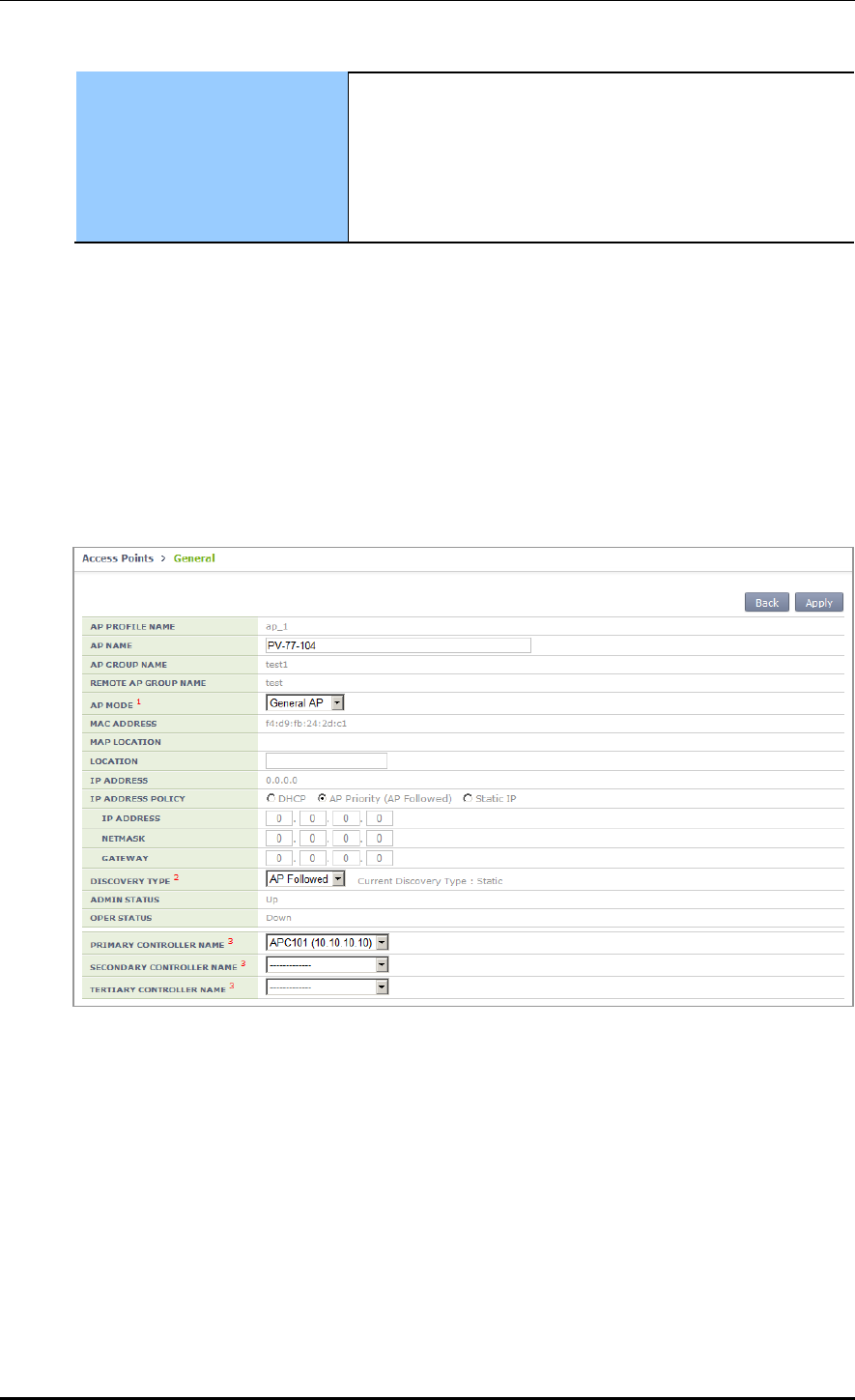
CHAPTER 4. AP Connection Management
© SAMSUNG Electronics Co., Ltd. page 179 of 628
Ethernet ports. Possible to set link aggregation for two
Ethernet ports. If link aggregation is activated, possible to set
the following mode:
- Both (Destination + Source)
- Destination
- Source
3) To check the information of a configured AP profile, use the ‘show ap detail
[AP_NAME]’ command.
Configuration using Web UI
In the menu bar of <WEC Main window>, select <Configuration> and then select the
<Access Points> AP selection <General> menu in the sub-menus.
The setting options in the General tab are as follows. Click the <Apply> button to apply
the settings.
Figure 77. AP Profile Setting (1)
AP NAME: AP name
AP GROUP NAME: Indicates name of the AP GROUP to which the AP belongs.
REMOTE AP GROUP NAME: Indicates name of the REMOTE AP GROUP to which
the AP belongs.
AP MODE: AP operational mode (General AP/Root AP/Repeater AP/Sniffer AP)
MAC ADDRESS: Cannot be changed to the MAC address of an AP.
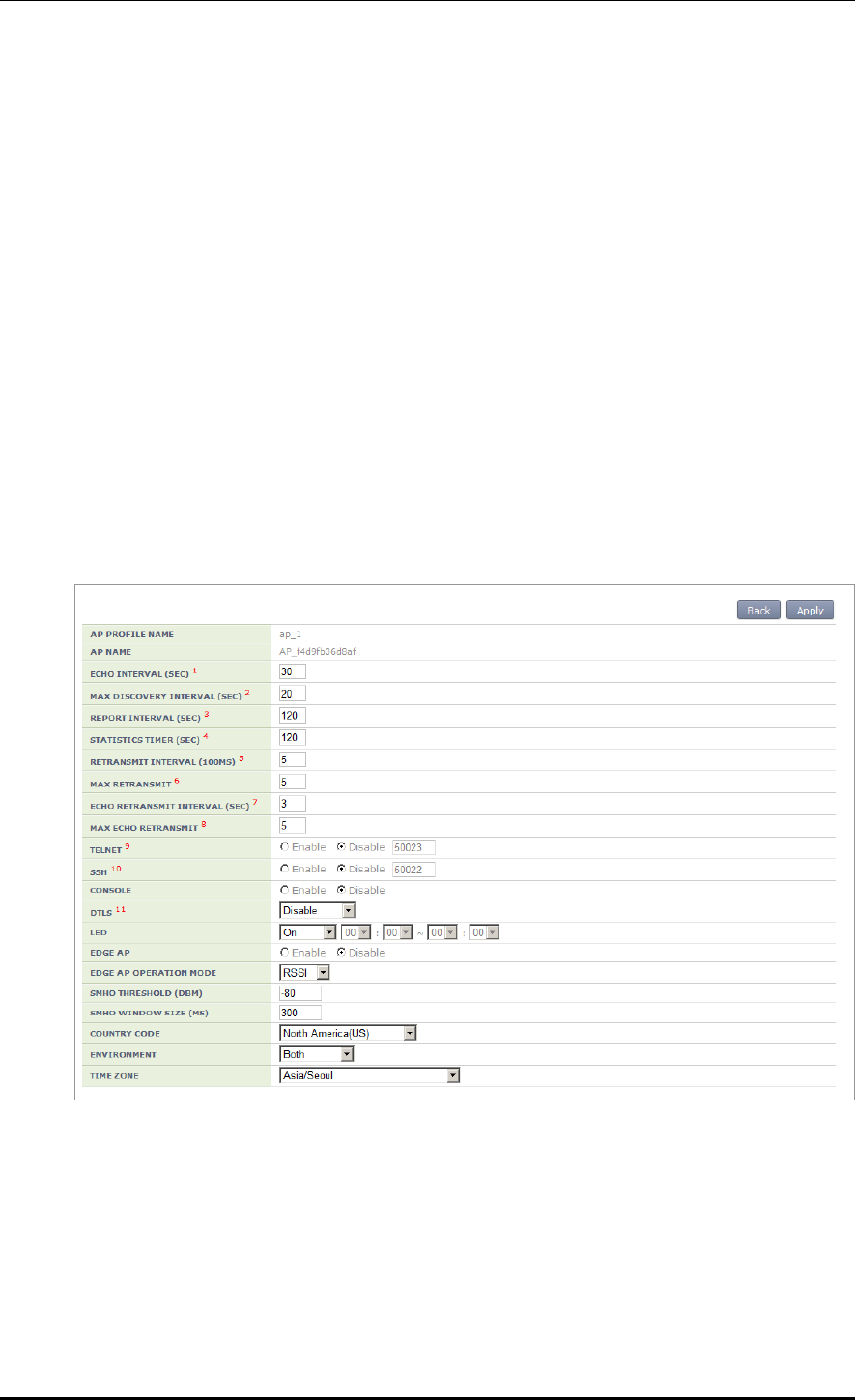
CHAPTER 4. AP Connection Management
© SAMSUNG Electronics Co., Ltd. page 180 of 628
MAP LOCATION
LOCATION: Information of location where an AP is installed
IP ADDRESS: IP address of AP
IP ADDRESS POLICY: IP address mode
DISCOVERY TYPE: AP discovery type
ADMIN STATUS: AP administrative status
OPER STATUS: Current AP operational status
PRIMARY CONTROLLER NAME, SECONDARY CONTROLLER NAME,
TERTIARY CONTROLLER NAME: Redundancy mode
For WEC8050, the TERTIARY CONTROLLER NAME is not supported.
In the menu bar of <WEC Main window>, select <Configuration> and then select the
<Access Points> AP <Advanced> menu in the sub-menus.
The setting options in the Advance tab are as follows. Fill in each item and click the
<Apply> button to apply the settings.
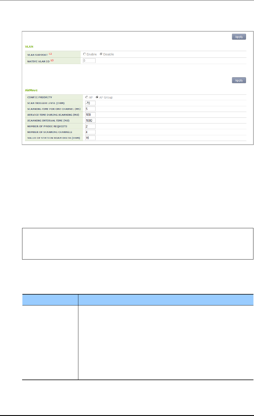
CHAPTER 4. AP Connection Management
© SAMSUNG Electronics Co., Ltd. page 181 of 628
Figure 78. AP Profile Setting (2)
4.2.4.3 AP Mode Configuration
Configuration using CLI
To configure AP mode, execute the command as follows.
1) Go to configure AP configuration AP profile mode of CLI.
WEC8500# configure terminal
WEC8500/configure# ap ap_1
WEC8500/configure/ap ap_1# profile
WEC8500/configure/ap ap_1/profile#
2) Configure the AP mode.
ap-mode [MODE]
Parameter
Description
MODE
AP operation mode (generalAp/rootAp/repeaterAp/snifferAp)
- generalAp: Typical operation mode. Default value.
- rootAp: AP mode where a repeater AP can be connected.
- repeasterAp: AP mode that is connected to a wireless area and the APC
through the root AP.
- snifferAp: AP mode where the packets operating in a wireless
environment can be captured.
- relayAp: An AP mode which connects a root AP and a repeater AP
wirelessly
3) To check the information of a configured AP, use the ‘show ap detail [AP_NAME]’
command.
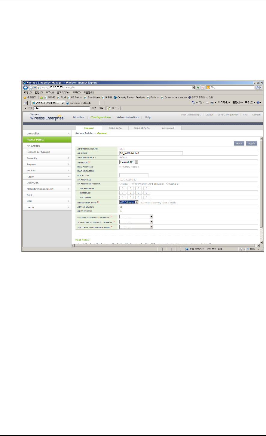
CHAPTER 4. AP Connection Management
© SAMSUNG Electronics Co., Ltd. page 182 of 628
Configuration using Web UI
In the menu bar of <WEC Main window>, select <Configuration> and then select the
<Access Points> AP selection <General> menu in the sub-menus.
After selecting the AP MODE NAME item, click the <Apply> button to apply the
configuration.
Figure 79. AP mode configuration
4.2.4.4 AP CLI Access Account
The APC operator can add or remove account information relating to the AP CLI. When the
APC is first installed, a default account is provided (id: root, password: samsung).
Up to three AP CLI accounts can be added, and at least one account must be configured.
Therefore, if there is only one remaining account, it cannot be deleted.
(* While each account may be in any of the three available levels (Administrator/Operator/
Monitor), there are currently no functional differences for the APs.)
Configuration using CLI
Execute the following commands to configure the AP access account.
1) Go to configure APC mode of CLI.
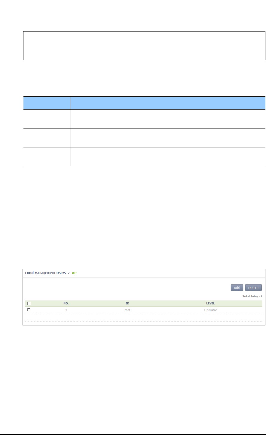
CHAPTER 4. AP Connection Management
© SAMSUNG Electronics Co., Ltd. page 183 of 628
WEC8500# configure terminal
WEC8500/configure# apc
WEC8500/configure/apc #
2) Add an AP CLI account.
ap-account [ID] [PASSWORD] [LEVEL]
Parameter
Description
ID
This is the ID of the AP CLI account.
Only an alphanumeric value of up to eight characters can be entered.
Password
This is the password of the AP CLI account.
Only an alphanumeric value of up to eight characters can be entered.
Level
This is the level of the AP CLI account.
Available values are administrator/operator/monitor.
3) An account can be deleted by entering the 'no' parameter as shown below.
no ap-account [ID]
4) Use the ‘show apc ap-account’ command to retrieve the AP configuration information.
Configuration using Web UI
In the menu bar of <WEC Main Window>, select <Configuration>, and then select
<Local Management Users> AP in the submenu.
Click the ‘Add’ or ‘Delete’ button to add or delete the AP CLI account.
Figure 80. AP CLI Account Add/Remove Window

CHAPTER 4. AP Connection Management
© SAMSUNG Electronics Co., Ltd. page 184 of 628
4.2.4.5 AP SNMP Agent Configuration
The APC operator can configure SNMP Agent settings for all APs.
Configuration using CLI
Execute the following commands to configure the SNMP Agent settings of the AP.
1) Go to configure snmp ap mode of CLI.
WEC8500# configure terminal
WEC8500/configure# snmp
WEC8500/configure/snmp# ap
WEC8500/configure/snmp/ap#
2) Configure the snap agent information of the AP.
Enable/disable SNMP of the AP.
enable or no enable
Configure the SNMP port number of the AP.
Port [PORT NUMBER]
Configure the Read Only Community Name of the AP.
ro-community [COMMUNITY NAME]
Configure the Write Only Community Name of the AP.
rw-community [COMMUNITY NAME]
Configure the user information of the AP.
Use r[USER NAME] [AUTHENTICATION TYPE] [AUTHENTICATION KEY]
[PRIVATE PROTOCOL] [PRIVATE KEY]
Parameter
Description
PORT NUMBER
This is the SNMP port number.
COMMUNITY NAME
This is the SNMP Read Only or Write Only Community name.
USER NAME
This is the SNMP user name.
AUTHENTICATION TYPE
This is the SNMP authentication type. Either of the following two
can be selected:
- MD5
- SHA
AUTHENTICATION KEY
A number in the range of 8 to 20 can be entered.
PRIVATE PROTOCOL
Either of the following two can be selected:
- DES
- AES
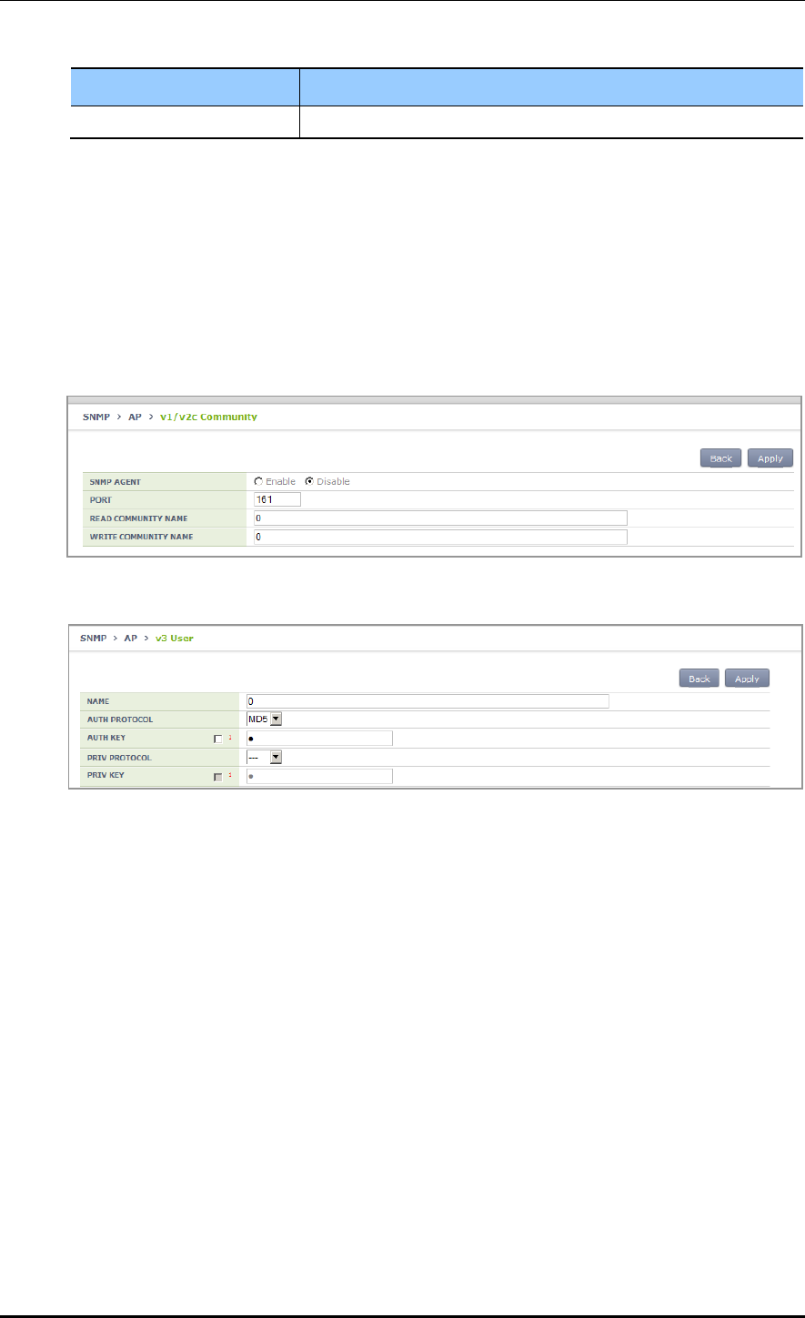
CHAPTER 4. AP Connection Management
© SAMSUNG Electronics Co., Ltd. page 185 of 628
Parameter
Description
PRIVATE KEY
A number in the range of 8 to 20 can be entered.
3) Use the ‘show snmp ap’ command to retrieve the agent information configured for the
AP.
Configuration using Web UI
In the menu bar of <WEC Main Window>, select <Administration>, select <AP> in the
submenu, and then select <v1/v2c Community> or <v3 User> to configure the SNMP
agent information.
Figure 81. AP SNMP v1/v2c Community Configuration Window
Figure 82. AP v3 User Configuration Window

CHAPTER 4. AP Connection Management
© SAMSUNG Electronics Co., Ltd. page 186 of 628
4.2.5 Information Management
The APC manages the history statistics information, real-time interface statistics
information, and tech support information of the AP.
AP History Statistics
The AP transmits the interface (WAN and WLAN) and CPU load/memory usage statistics
information collected for 5 min. to the APC. The APC forwards the information to the
WEM via FTP. If the APC does not interoperate with the WEM, the APC stores the
information for 3 days.
AP real-time statistics
If the APC requests the interface information to an AP, the AP transmits the interface
information (WAN and WLAN) to the APC at every 5 second and the APC stores the
information in its internal DB. An operator can retrieve the information by using CLI or WEC.
AP Tech Support
If there occurs a problem with a specific AP, an operator can download the Tech Support
information from the AP. Execute the following command to use the function.
The Tech Support from an AP includes the following information.
System log message file
System crash information file
System report files (status/configuration information)
Core file used to check application malfunctioning
4.2.5.1 History Statistics Information
To check the history statistics information relay status of an AP, use the ‘show ap stats-
history’ command.
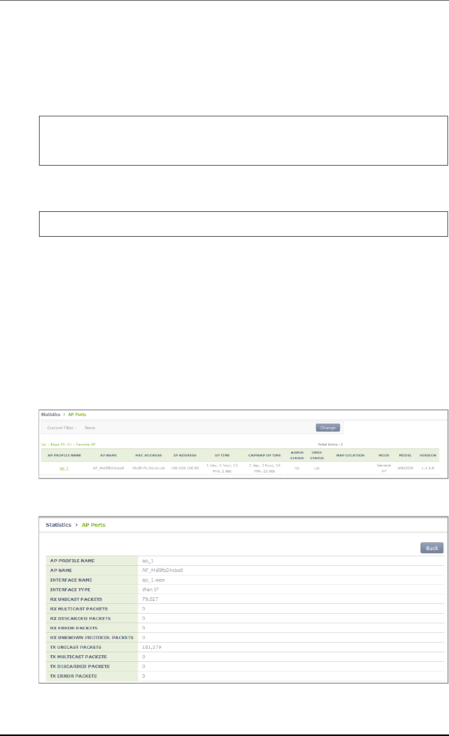
CHAPTER 4. AP Connection Management
© SAMSUNG Electronics Co., Ltd. page 187 of 628
4.2.5.2 Real-time Interface Statistics Information
Configuration using CLI
1) Go to configure AP configuration.
WEC8500# configure terminal
WEC8500/configure# ap ap_1
WEC8500/configure/ap ap_1#
2) Configure to make real-time interface statistics information updated periodically.
WEC8500/configure/ap ap_1# get-if-stats
3) To check the interface statistics information of an AP, use the ‘show ap if-stats
[AP_NAME]’ command.
Configuration using Web UI
In the menu bar of <WEC Main window>, select <Monitor> and then select the
<Statistics> <AP Ports> menu in the sub-menus.
As shown below, you can retrieve the real-time interface statistics of the AP.
Select an item in the list, and then you can check detail information.
Figure 83. AP Ports window
Figure 84. AP Ports detail information window
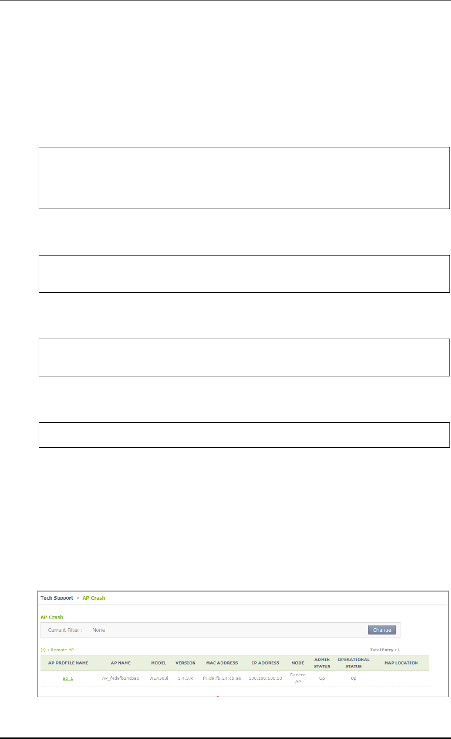
CHAPTER 4. AP Connection Management
© SAMSUNG Electronics Co., Ltd. page 188 of 628
4.2.5.3 Tech Support Information
Execute the below command to download the Tech Support information from an AP.
Configuration using CLI
1) Go to configure AP configuration tech-support of CLI.
WEC8500# configure terminal
WEC8500/configure# ap [ap profile name]
WEC8500/configure/ap ap_1# tech-support
WEC8500/configure/ap ap_1/tech-support#
2) Request the coredump file of the AP.
WEC8500/configure/ap ap_1/tech-support# get-coredump (system / radio-
coredump)
3) Request the crashfile of the AP.
WEC8500/configure/ap ap_1/tech-support# get-crash-file (system /
radio-coredump)
4) Request the log file of the AP.
WEC8500/configure/ap ap_1/tech-support# get-log-file
5) Use ‘show ap tech-support’ command to check the Tech Support file information of
APs. Operator can use FTP or sFTP to download Tech Support files.
Configuration using Web UI
In the menu bar of <WEC Main window>, select <Administrator> and then select the
<Tech Support> <AP Crash> menu in the sub-menus.
By clicking the profile name of an AP, operator can download the Tech Support file.
Figure 85. AP Tech Support Information Receiving Window

CHAPTER 4. AP Connection Management
© SAMSUNG Electronics Co., Ltd. page 189 of 628
4.2.6 Outdoor AP Configuration
The APC system provides outdoor AP connection diagnostic functions for outdoor APs.
The AP connection diagnostics function checks ping status of outdoor APs and displays the
results on the operator’s monitor.
Procedure of using the outdoor AP connection diagnostics function is as follows:
1) The operator creates/deletes outdoor APWEC using CLI.
2) The APC system periodically pings the outdoor AP to check the network connection of
the AP and stores the results.
3) The operator uses the WEC, WEM or CLI to determine network connection status of
the outdoor AP.
Concerning outdoor AP count:
1) Outdoor APs are not included in the AP count of the APC license.
2) Outdoor APs are not included in the ordinary AP count.
3) The maximum up-ported outdoor AP count is 300 for the WEC8500 model and 75 for
the WEC8050 model.
4) The APC system can retrieve the total/up/down outdoor AP count using the WEC or
CLI.
4.2.6.1 Outdoor AP Addition/Removal
The APC system allows creation/deletion of outdoor AP information using the WEC or CLI.
Configuration using CLI
1) Go to configure mode of CLI.
WEC8500# configure terminal
WEC8500/configure#
2) Create or delete an AP. Use the ‘no’ parameter in front of the command to delete an
outdoor AP.
outdoor-ap [PROFILE_NAME] [MAC_ADDRESS] [IP_ADDRESS]
no outdoor-ap [PROFILE_NAME]
3) Create or delete an outdoor AP. Use the ‘no’ parameter in front of the command to
delete an outdoor AP.
4) Use the ‘show ap summary’ command to check the outdoor AP information.
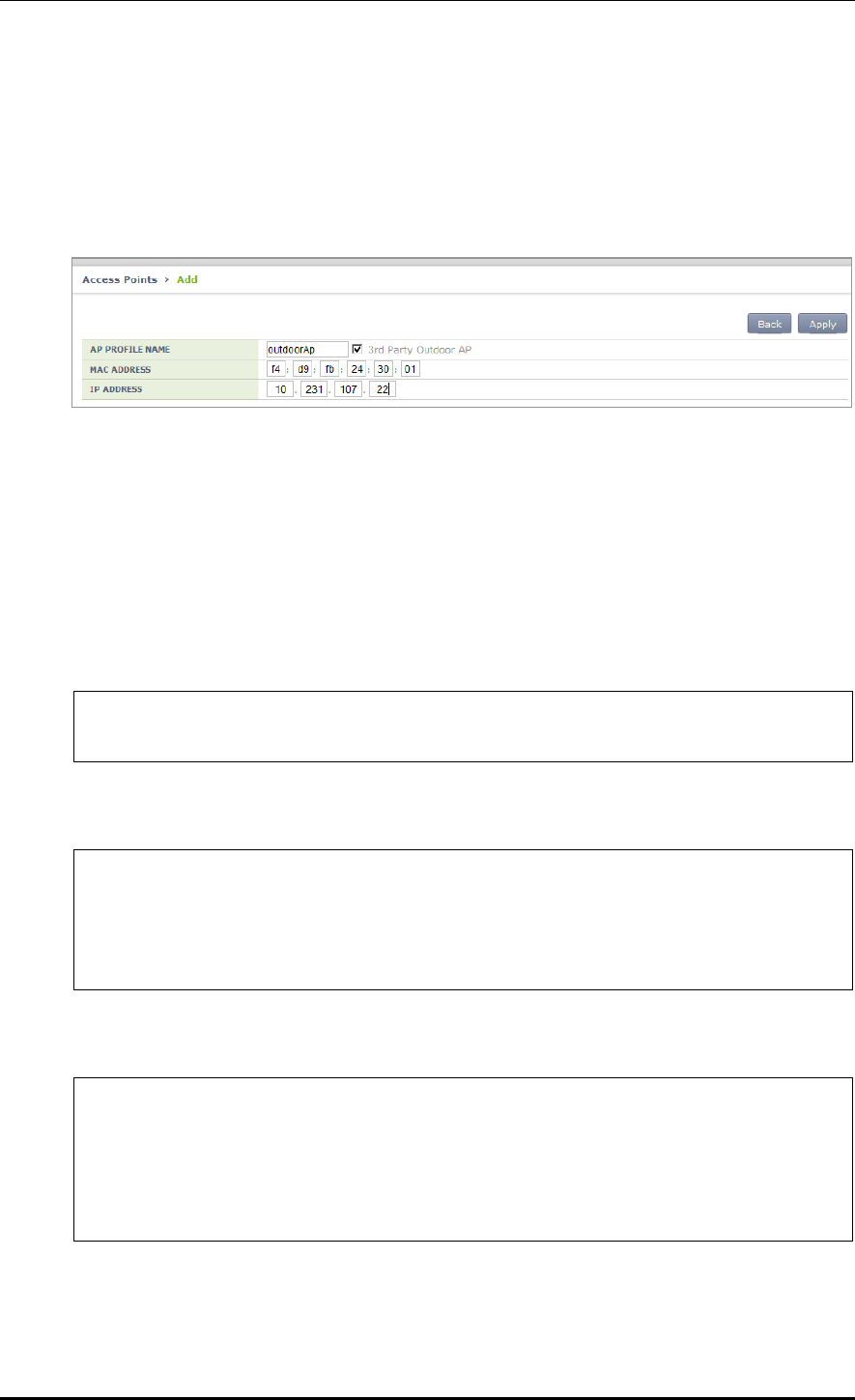
CHAPTER 4. AP Connection Management
© SAMSUNG Electronics Co., Ltd. page 190 of 628
Configuration using Web UI
In the menu bar of <WEC Main Window>, select <Configuration> and then select the
<Access Points> menu in the sub-menus. To create an outdoor AP, click <Add>, select
<3rd Party Outdoor AP>, enter AP PROFILE NAME, MAC ADDRESS, and IP
ADDRESS, and then select <Apply>.
Figure 86. Outdoor AP Create Window
4.2.7 AP Package Upgrade
Configuration using CLI (Upgrade Function)
To manage the AP upgrade function, execute the command as follows:
1) Go to configure AP configuration mode of CLI.
WEC8500# configure terminal
WEC8500/configure# ap ap_1
2) Request the image file of an AP to upgrade.
WEC8500/configure/ap ap_1# upgrade-request weafama_1.2.4.R.bin
WARNING: AP will be upgrade.
Are you sure you want to continue? (y/n) : y
WEC8500/configure/ap ap_1#
3) To check the upgrade file information of the requested AP, use the following command.
WEC8500/configure/ap ap_1# show ap upgrade list
/* (RC/FR/RC) : RetryCount/FailReason/RebootCause
/* Pri : VersionPriority (MD-model,A-AP config)
AP_ID Model Version(config/current) Status(RC/FR/RC) Pri force
1 WEA302i 1.2.4.R/ 1.2.4.R Success( 0/ 0/146) AP No

CHAPTER 4. AP Connection Management
© SAMSUNG Electronics Co., Ltd. page 191 of 628
Configuration using CLI (Upgrade environment)
To configure AP upgrade related environment, the following command is provided.
First of all, go to the configure AP-all upgrade mode of CLI.
WEC8500# configure terminal
WEC8500/configure# ap-all
WEC8500/configure/ap-all# upgrade
WEC8500/configure/ap-all/upgrade#
[select-package]
This command configures a package to use during AP upgrade.
select-package [UPGRADE_TYPE] [FILE_NAME]
Parameter
Description
UPGRADE_TYPE
Configures upgrade type (default/quick-upgrade/predownload)
- default: AP image that is referred to during provision upgrade.
- quick-upgrade: AP image that is referred to for entire AP upgrade
upon an operator’s request.
- predownload: AP image that is referred to download AP image to
AP during entire AP upgrade.
FILE_NAME
Image file name that will be used for AP upgrade
[target]
During entire upgrade, you can select whether to maintain individual configured AP
version of an AP or perform upgrade.
Target [AP UPGRADE TARGET]
Parameter
Description
UPGRADE TARGET
Upgrade target (all/ keeping-individual)
- all: Perform upgrade for all the APs. (default)
- keeping-individual: While maintaining individually configured ap
version, perform upgrade for the rest APs.
[transfer-protocol]
This command selects a transmission protocol that is used to transmit the package file of an
AP from the WEC8500 to the AP.
Transfer-protocol [AP TRANSFER MODE]
Parameter
Description
TRANSFER_MODE
File transmission protocol (ftp/sftp)
- ftp: ftp is used for file transmission.
- sftp: sftp is used for file transmission.

CHAPTER 4. AP Connection Management
© SAMSUNG Electronics Co., Ltd. page 192 of 628
[max-download]
This command configures the maximum number of simultaneous downloads when
transmitting the package file of an AP from the APC to the AP.
Max-download [COUNT]
Parameter
Description
COUNT
Maximum number of simultaneous downloads of AP image
file (range: 1-50, default: 10)
[max-retry]
This command configures maximum number of re-attempts when AP upgrade is failed.
Max-retry [COUNT]
Parameter
Description
COUNT
Maximum number of AP upgrade re-attempts
(range: 1-10, default: 3)
[start]
This command provides the entire AP upgrade function.
start [UPGRADE_TYPE]
Parameter
Description
UPGRADE_TYPE
Configures upgrade type (quick-upgrade/predownload)
- quick-upgrade: Perform entire ap upgrade upon an
operator’s request.
- predownload: Download ap image to ap first during entire
ap upgrade.
If you perform package upgrade after configuring AP upgrade type to predownload, restart
all the APs in the following methods.
WEC8500# configure terminal
WEC8500/configure# ap-all
WEC8500/configure/ap-all# reboot upgrade
[stop]
This command provides the function of stopping the image upgrade of all the APs.
stop
[show ap upgrade]
To check the upgrade information of an AP, use the following command.
show ap upgrade summary
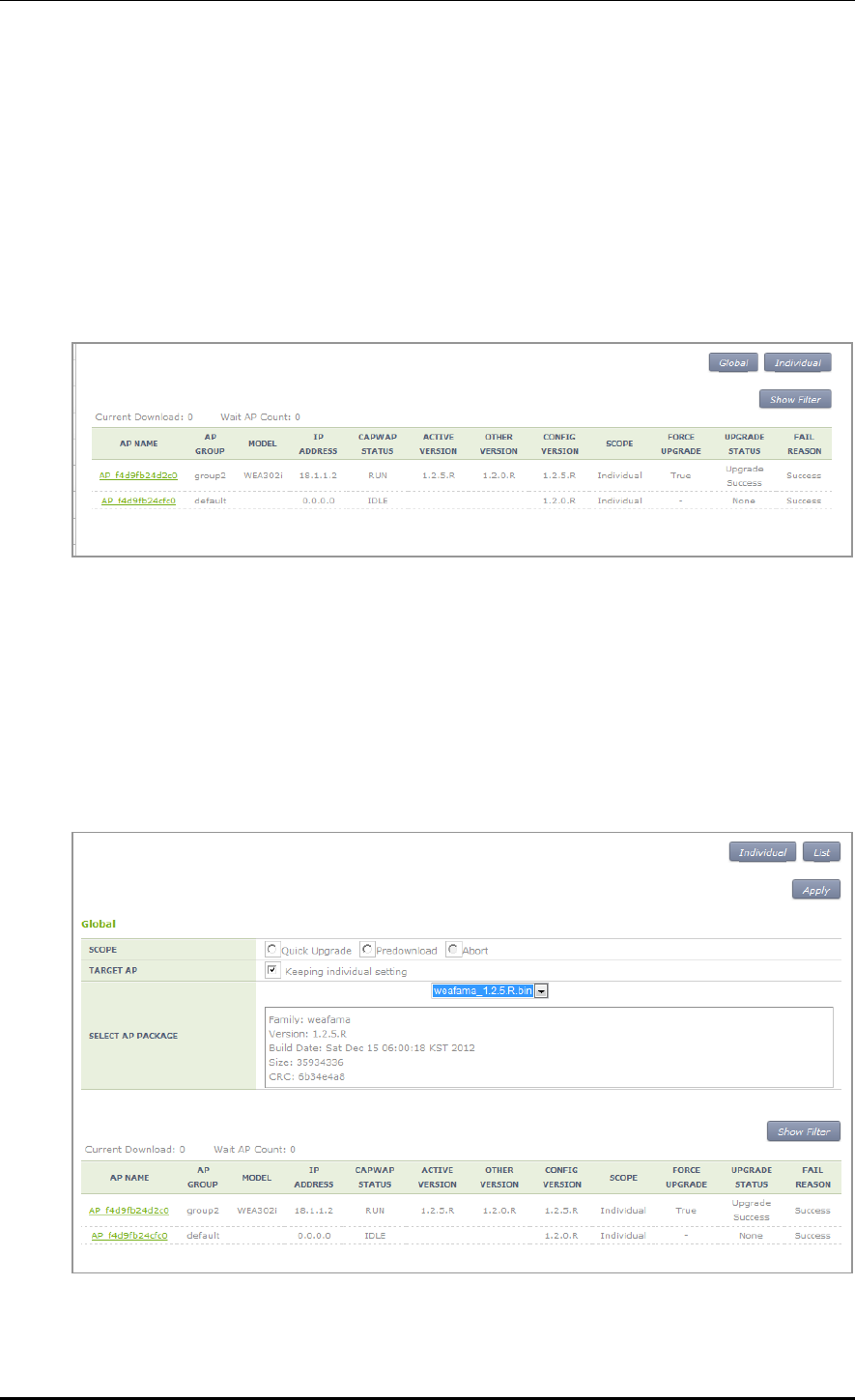
CHAPTER 4. AP Connection Management
© SAMSUNG Electronics Co., Ltd. page 193 of 628
Configuration using Web UI
In the menu bar of <WEC Main window>, select <Administrator> and then select
<Package Upgrade> <AP> menu in the sub menu.
You can perform AP upgrade in the AP Upgrade tab and configure upgrade related
environment in the Advanced tab.
[AP Upgrade tab]
AP Upgrade tab upgrades all the APs or a specific AP.
Figure 87. AP upgrade
The procedure of entire AP upgrade is as follows:
1) In the AP Upgrade window, click the <Global> button.
2) The <Global> area is displayed on the window. After configuring each item, click the
<Apply> button.
Figure 88. AP upgrade-global
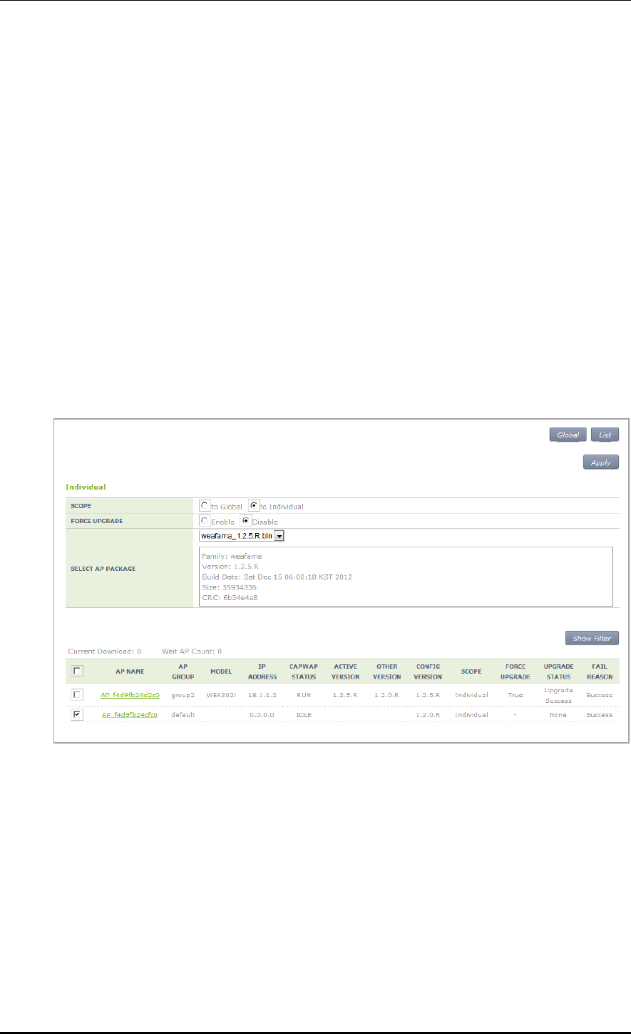
CHAPTER 4. AP Connection Management
© SAMSUNG Electronics Co., Ltd. page 194 of 628
SCOPE: Selects upgrade method. To make the AP working as the package
immediately after upgrade, select Quick Upgrade. To download the package to the
AP, select the Predownload menu.
TARGE AP: Select an AP target to upgrade. If you select <Keeping individual
setting>, an AP that is configured as individual is excluded from upgrade.
SELECT AP PACKAGE: Selects an AP package to upgrade.
3) If the SCOPE setup is Predownload upgrade, you must restart the AP once download is
completed. After selecting the <Administration> <Reboot> <AP> menu, select
Reboot All with Upgrade to restart the AP.
To upgrade a specific AP, follow the below procedure.
1) In the AP Upgrade window, click the <Individual> button.
2) The individual area is displayed on the window. After configuring each item, click the
<Apply> button.
Figure 89. AP upgrade-individual
SCOPE: Selects upgrade method. The <to individual> upgrades the selected AP to
a specific package and the <to global> makes a select AP working as global.
FORCE UPGRADE: Enable or disable
SELECT AP PACKAGE: Selects an AP package to upgrade..
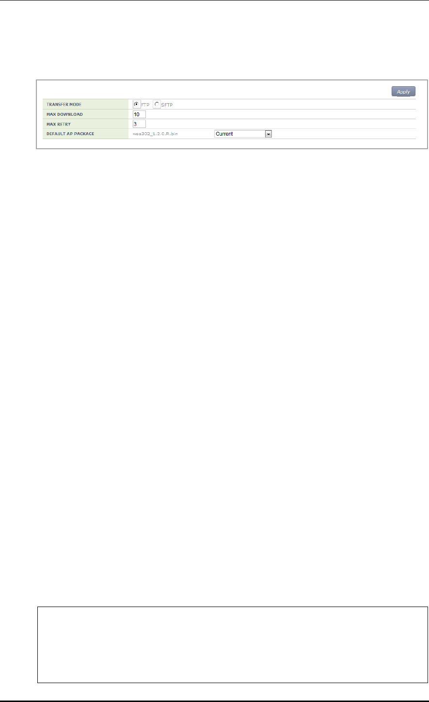
CHAPTER 4. AP Connection Management
© SAMSUNG Electronics Co., Ltd. page 195 of 628
[Advanced tab]
Configures AP upgrade related environment settings.
Figure 90. AP upgrade-advanced
TRANSFER MODE: Selects a protocol that transmits an AP package.
MAX DOWNLOAD: Configures maximum number of sessions that can be
downloaded simultaneously.
MAX RETRY: Configures maximum number of re-attempts when AP upgrade is
failed.
DEFAULT AP PACKAGE: Select an AP package that will be used for automatic
upgrade during AP joint.
4.2.8 Remote AP Package Upgrade
APs in a remote group can be upgraded by downloading an AP package from a specific AP.
This is useful for efficient management of APC-AP bandwidth.
A master AP can be selected for each AP package model. After downloading an AP package
from the APC, the master AP allows the AP package to be downloaded to other APs in the
remote group.
The operator can manage AP upgrade of the APs in the remote group by checking the AP
package download status in the remote group and performing reboot and upgrade.
4.2.8.1 Activating Upgrade
The operator can enable/disable the AP upgrade in the remote group.
When the AP upgrade is enabled, version priority in AP upgrade status changes to Remote.
Configuration using CLI
Example:
WEC8500# configure terminal
WEC8500/configure# ap-group rUpgrade
WEC8500/configure/ap-group rUpgrade# remote
WEC8500/configure/ap-group rUpgrade/remote# upgrade
WEC8500/configure/ap-group rUpgrade/remote/upgrade# enable
WEC8500/configure/ap-group rUpgrade/remote/upgrade# no enable

CHAPTER 4. AP Connection Management
© SAMSUNG Electronics Co., Ltd. page 196 of 628
CLI for checking configuration:
WEC8500 # show remote-ap-group upgrade config rUpgrade
================== Remote Ap Group Upgrade Config =================
Group Name : rUpgrade
Enable : Enable
Type : Default
Mode : FTP
Path : package/ap
PortNum : 21
MAXretries : 3
ForceOption : Disable
weafama : (APID:0, IP:0.0.0.0)
: ()
weafamb : (APID:0, IP:0.0.0.0)
: ()
WEC8500# show remote-ap-group upgrade list rUpgrade
/* (RC/FR/RC) : RetryCount/FailReason/RebootCause
AP_ID Model Version(config/current) Status(RC/FR/RC) MasterAp
1 WEA303i Remote/1.7.0.U2 None( 0/ 0/128) -
2 WEA312i Remote/1.7.0.U2 None( 0/ 0/128) -
3 WEA303i Remote/1.7.0.U1 None( 0/ 0/128) -
Configuration using Web UI
Administration > Package Upgrade > Remote AP Group
Example:
Figure 91. Remote AP Group Upgrade Activation_1

CHAPTER 4. AP Connection Management
© SAMSUNG Electronics Co., Ltd. page 197 of 628
Figure 92. Remote AP Group Upgrade Activation_2
4.2.8.2 Master AP Configuration (Optional)
The operator can configure the master AP for AP upgrade in the remote group.
If none is configured, a master AP is automatically selected.
Configuration using CLI
Example:
WEC8500# configure terminal
WEC8500/configure# ap-group rUpgrade
WEC8500/configure/ap-group rUpgrade# remote
WEC8500/configure/ap-group rUpgrade/remote# upgrade
WEC8500/configure/ap-group rUpgrade/remote/upgrade# select-masterAP
ap_1
WEC8500/configure/ap-group rUpgrade/remote/upgrade# delete-masterAP
[weafama/weafamb]
CLI for checking configuration:
WEC8500# show remote-ap-group upgrade config rUpgrade
================== Remote Ap Group Upgrade Config =================
Group Name : rUpgrade
Enable : Enable
Type Default
Mode : FTP
Path : package/ap
PortNum : 21
MAXretries : 3
ForceOption : Disable
weafama : ap_1 (APID:1, IP:10.10.10.160)
: ()
weafamb : (APID:0, IP:0.0.0.0)
: ()
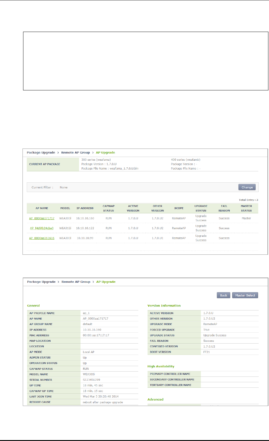
CHAPTER 4. AP Connection Management
© SAMSUNG Electronics Co., Ltd. page 198 of 628
WEC8500# show remote-ap-group upgrade list rUpgrade
/* (RC/FR/RC) : RetryCount/FailReason/RebootCause
AP_ID Model Version(config/current) Status(RC/FR/RC) MasterAp
1 WEA303i Global/1.7.0.U2 None( 0/ 0/128) MasterApCfg
2 WEA312i Global/1.7.0.U2 None( 0/ 0/146) -
3 WEA303i Global/1.7.0.U1 None( 0/ 0/146) -
Configuration using Web UI
Administration > Package Upgrade > Remote AP Group
Example:
Figure 93. Checking Master AP Configuration
Figure 94. Checking Master AP Configuration

CHAPTER 4. AP Connection Management
© SAMSUNG Electronics Co., Ltd. page 199 of 628
4.2.8.3 AP Package Configuration
The operator can configure an AP package to upgrade in the remote group.
Configuration using CLI
Example:
WEC8500# configure terminal
WEC8500/configure# ap-group rUpgrade
WEC8500/configure/ap-group rUpgrade# remote
WEC8500/configure/ap-group rUpgrade/remote# upgrade
WEC8500/configure/ap-group rUpgrade/remote/upgrade# select-package
weafama weafama_1.7.0.U.bin
WEC8500/configure/ap-group rUpgrade/remote/upgrade#delete-package
[weafama/weafamb]
CLI for checking configuration:
WEC8500# show remote-ap-group upgrade config rUpgrade
================== Remote Ap Group Upgrade Config =================
Group Name : rUpgrade
Enable : Enable
Type : Default
Mode : FTP
Path : package/ap
PortNum : 21
MAXretries : 3
ForceOption : Disable
weafama : ap_1 (APID:1, IP:10.10.10.160)
: weafama_1.7.0.U.bin (1.7.0.U)
weafamb : (APID:0, IP:0.0.0.0)
: ()
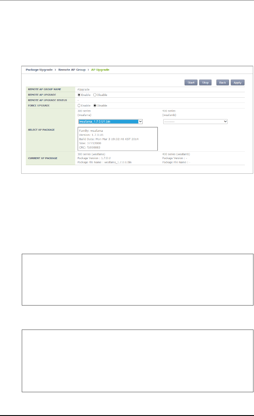
CHAPTER 4. AP Connection Management
© SAMSUNG Electronics Co., Ltd. page 200 of 628
Configuration using Web UI
Administration > Package Upgrade > Remote AP Group
Example:
Figure 95. AP Package Configuration
4.2.8.4 Starting AP Upgrade
The operator can start or stop AP upgrade in the remote group.
Configuration using CLI
Example:
WEC8500# configure terminal
WEC8500/configure# ap-group rUpgrade
WEC8500/configure/ap-group rUpgrade# remote
WEC8500/configure/ap-group rUpgrade/remote# upgrade
WEC8500/configure/ap-group rUpgrade/remote/upgrade# start
WEC8500/configure/ap-group rUpgrade/remote/upgrade# stop
CLI for checking configuration:
WEC8500# show remote-ap-group upgrade config rUpgrade
================== Remote Ap Group Upgrade Config =================
Group Name : rUpgrade
Enable : Enable
Type : Predownload
Mode : FTP
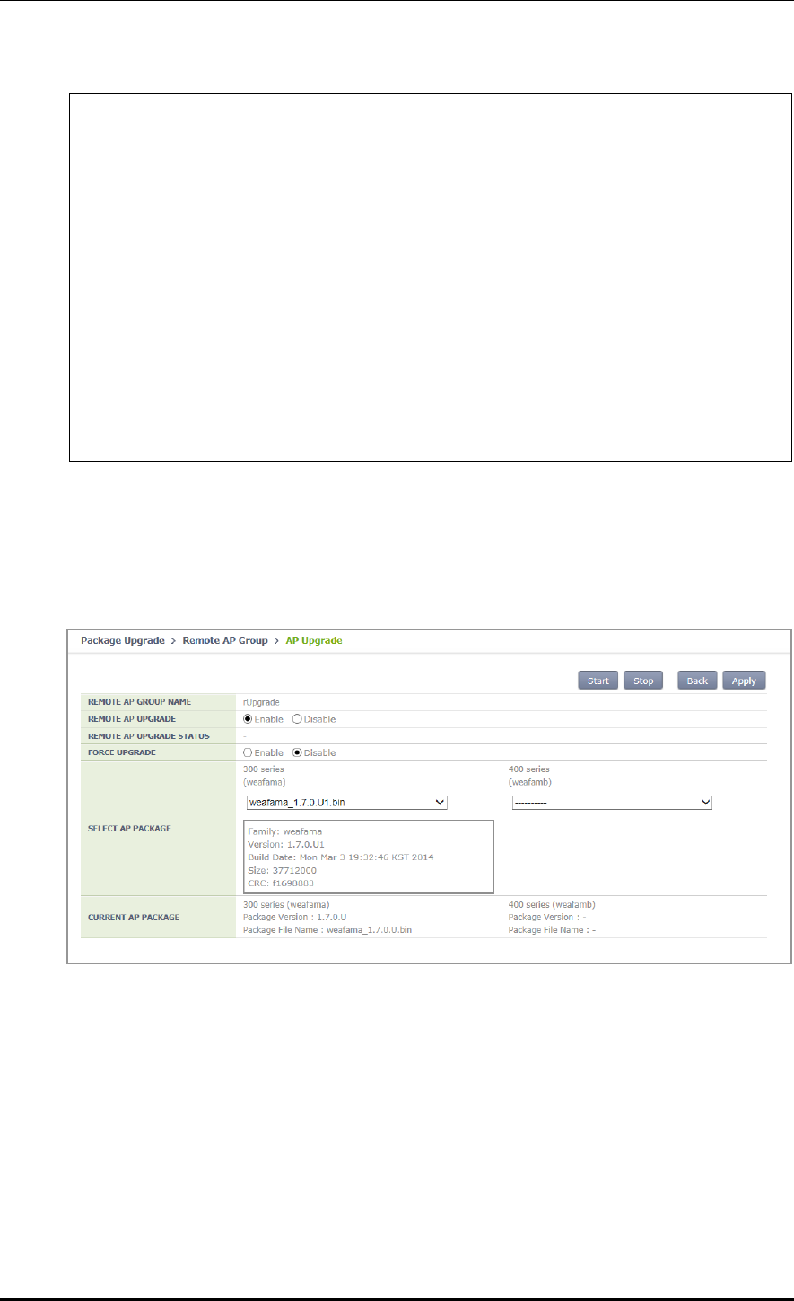
CHAPTER 4. AP Connection Management
© SAMSUNG Electronics Co., Ltd. page 201 of 628
Path : package/ap
PortNum : 21
MAXretries : 3
ForceOption : Disable
weafama : ap_1 (APID:1, IP:10.10.10.160)
: weafama_1.7.0.U.bin (1.7.0.U)
weafamb : (APID:0, IP:0.0.0.0)
: ()
WEC8500# show remote-ap-group upgrade list rUpgrade
/* (RC/FR/RC) : RetryCount/FailReason/RebootCause
AP_ID Model Version(config/current) Status(RC/FR/RC) MasterAp
1 WEA303i Remote/1.7.0.U2 DownloadSuccess( 0/ 0/128) MasterApCfg
2 WEA312i Remote/1.7.0.U2 DownloadSuccess( 0/ 0/146) -
3 WEA303i Remote/1.7.0.U2 DownloadSuccess( 0/ 0/146) -
Configuration using Web UI
Administration > Package Upgrade > Remote AP Group
Example:
Figure 96. Starting AP Upgrade

CHAPTER 4. AP Connection Management
© SAMSUNG Electronics Co., Ltd. page 202 of 628
4.2.8.5 Restarting and Upgrading AP
After downloading the AP package, APs in the remote group are restarted so that they can
run on the upgraded version.
Configuration using CLI
Example:
WEC8500# configure terminal
WEC8500/configure# ap-group rUpgrade
WEC8500/configure/ap-group rUpgrade# remote
WEC8500/configure/ap-group rUpgrade/remote# reboot upgrade
CLI for checking configuration:
WEC8500# show remote-ap-group upgrade config rUpgrade
================== Remote Ap Group Upgrade Config =================
Group Name : rUpgrade
Enable : Enable
Type : Default
Mode : FTP
Path : package/ap
PortNum : 21
MAXretries : 3
ForceOption : Disable
weafama : ap_1 (APID:1, IP:10.10.10.160)
: weafama_1.7.0.U.bin (1.7.0.U)
weafamb : (APID:0, IP:0.0.0.0)
: ()
WEC8500# show remote-ap-group upgrade list rUpgrade
/* (RC/FR/RC) : RetryCount/FailReason/RebootCause
AP_ID Model Version(config/current) Status(RC/FR/RC) MasterAp
1 WEA303i Remote/1.7.0.U Success( 0/ 0/128) MasterApCfg
2 WEA312i Remote/1.7.0.U Success( 0/ 0/146) -
3 WEA303i Remote/1.7.0.U Success( 0/ 0/146) -
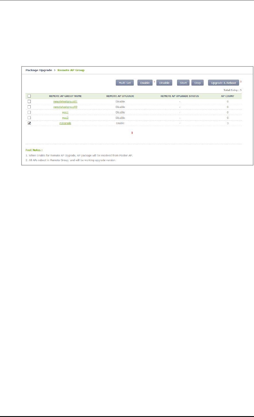
CHAPTER 4. AP Connection Management
© SAMSUNG Electronics Co., Ltd. page 203 of 628
Configuration using Web UI
Administration > Package Upgrade > Remote AP Group
Example:
Figure 97. Restarting and Upgrading AP

CHAPTER 5. WLAN Management
© SAMSUNG Electronics Co., Ltd. page 204 of 628
CHAPTER 5. WLAN Management
This chapter describes how to create and configure WLAN that is the most fundamental
basis for W-EP wireless LAN service.
5.1 WLAN Configuration
5.1.1 Basic WLAN Configuration
The WLAN profile helps configure and manage the WLAN connection service of an AP in
the APC. To use WLAN service, it is necessary to basically configure AP group and
interface group and specify Service Set Identifier (SSID).
Configuration using CLI
Go to the wlan configuration mode from the configure mode of CLI.
WEC8500# configure terminal
WEC8500/configure# wlan [WLAN ID]
Parameter
Description
WLAN_ID
WLAN ID (range: 1-255)
The WLAN configuration procedures are as follows:
1) Go to configure wlan configuration mode of CLI.
WEC8500# configure terminal
WEC8500/configure# wlan 1
WEC8500/configure/wlan 1#
2) Add WLAN to an AP group.
Configure an AP group to which WLAN service will be provided. The AP group
configuration is only possible in the AP group configuration mode instead of the wlan
configuration mode. The below configuration allocates wlan 1 to the apg_01 AP group.
CHAPTER 5. WLAN Management
© SAMSUNG Electronics Co., Ltd. page 205 of 628
A newly created WLAN is added to the ‘default’ AP group if the WLAN ID is in the
range of 1-16. If its WLAN ID is 17 or above, the WLAN is not included in the AP
group.
Maximum 16 WLANs can be allocated to each AP group.
WEC8500# configure terminal
WEC8500/configure# ap-group apg_01
WEC8500/configure/ap-group apg_01# add-wlan 1
3) Configure an interface group to which the WLAN service will be provided.
Several VLAN interfaces can be added to an interface group, and the WLAN service is
available only through the interface.
if-group [INTERFACE_GROUP_NAME]
4) Configure a SSID. The SSID is an ID used to connect to each wireless terminal to
provide the WLAN service.
Make sure to configure a SSID to use the WLAN service.
ssid [SSID_NAME]
5) Configure radio by selecting 2.4G, 5G or All (2.4G/5G).
radio [Radio ID: 1: 5 GHz, 2: 2.4 GHz, 3: ALL]
6) Configure whether to apply the WLAN service.
WEC8500/configure/wlan 1#enable
To apply the various WLAN services to multiple wireless terminals, create the
WLAN service in a profile format. Once the WLAN service is started, make each
AP use the WLAN service by downloading the profile.
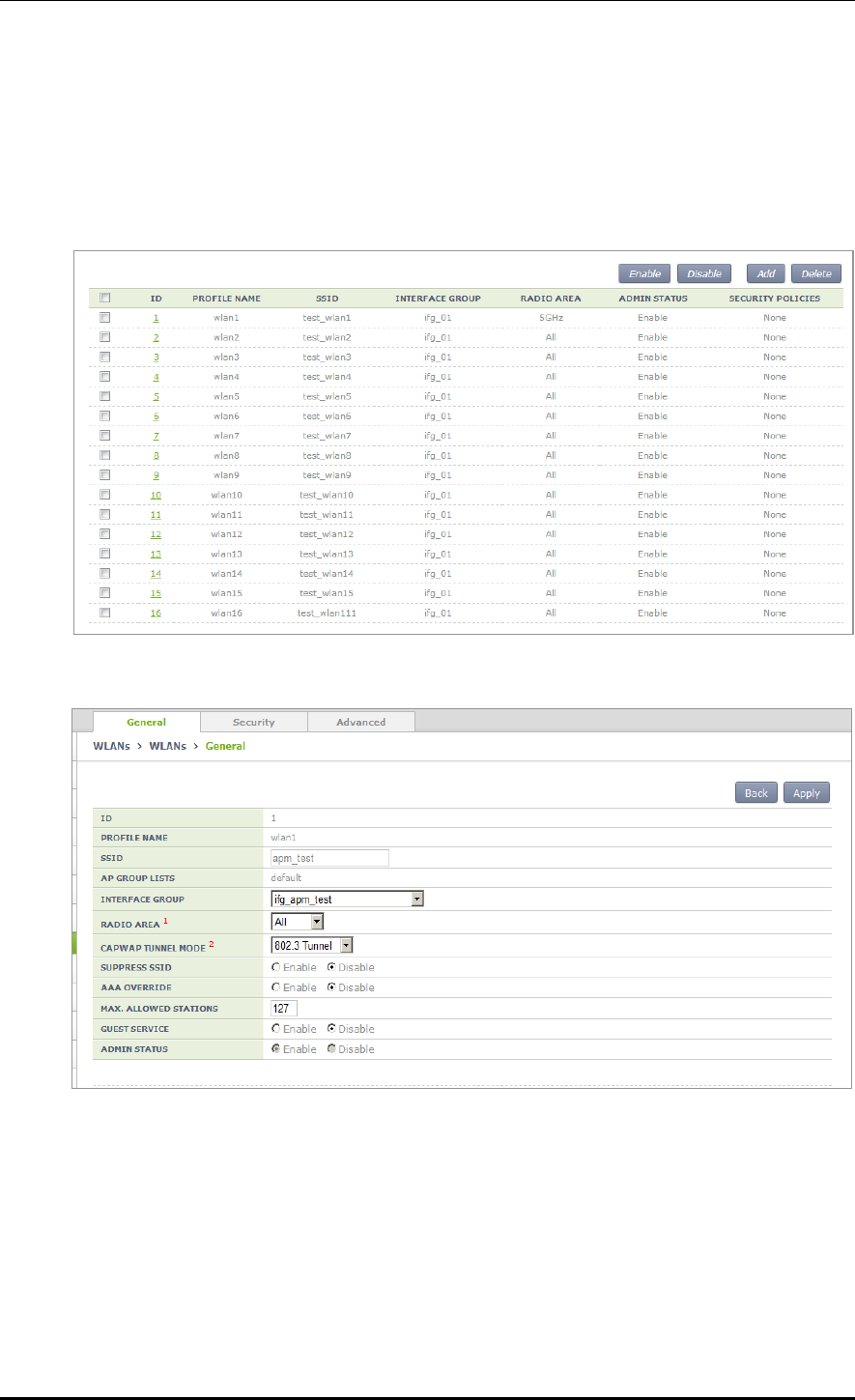
CHAPTER 5. WLAN Management
© SAMSUNG Electronics Co., Ltd. page 206 of 628
Configuration using Web UI
In the menu bar of <WEC Main window>, select <Configuration> and then select the
<WLANs> menu in the sub-menus. Select a WLAN ID to change in the WLANs screen
and go to the <General> tab. In the screen, you can use various functions such as adding or
deleting a WLAN.
Figure 98. WLAN basic configuration (1)
Figure 99. WLAN basic configuration (2)

CHAPTER 5. WLAN Management
© SAMSUNG Electronics Co., Ltd. page 207 of 628
You can configure various functions such as interface group and SSID, etc.
The configurations available in the General tab are as follows:
INTERFACE GROUP: Configures an interface group.
RADIO AREA: Configures a radio area.
CAPWAP TUNNEL MODE/LOCAL VLAN: Configures the local switching function.
SUPRESS SSID: Enables or disables the function.
AAA OVERRIDE: If the WLAN is enabled with the device authentication function
using a AAA server, the AAA-override function can be enabled so that the user-
specific settings configured in the AAA server are applied with priority over the APC
settings.
MAXIMUM ALLOWED STATIONS: Limits the number of users per WLAN.
GUEST SERVICE: Enables or disables the Guest service.
ADMIN STATUS: Enables or disables the function.
5.1.2 WLAN Additional Configuration
Each wireless terminal can receive a differentiated service according to the WLAN
configuration. The procedure of configuring the WLAN additional function is as follows.
Configuration using CLI
1) Go to configure wlan configuration mode of CLI.
WEC8500# configure terminal
WEC8500/configure# wlan 1
WEC8500/configure/wlan 1
2) If the WLAN is enabled with the device authentication function using a AAA server,
the AAA-override function can be enabled so that the user-specific settings configured
in the AAA server are applied with priority over the APC settings.
WEC8500/configure/wlan 1# aaa-override
3) Determine whether to configure the Guest service.
guest-flag
4) Configure a VLAN ID to use locally.
local-vlan [VLAN_ID]
Parameter
Description
VLAN_ID
VLAN ID (range: 1-4094)

CHAPTER 5. WLAN Management
© SAMSUNG Electronics Co., Ltd. page 208 of 628
5) Specify the service MAC type.
mac-type [MAC_TYPE]
Parameter
Description
MAC_TYPE
- localMac: An AP itself provides data service.
- splitMac: Provides data service through the APC.
6) Select a radio bandwidth to provide the WLAN service.
radio [RADIO]
Parameter
Description
RADIO
- 1: 5 GHz
- 2: 2.4 GHz
- 3: Supports both 5/2.4 GHz
7) Select whether to provide the SSID as hidden. If it is set to ‘hidden’, the SSID is not
found when other devices do searching.
suppress-ssid
8) Select the tunnel mode.
tunnel-mode [TUNNEL_MODE]
Parameter
Description
TUNNEL_MODE
- LocalBridging: Make all the user traffics are bridged at the AP.
- 8023Tunnel: Make all the user traffics are transmitted in the 802.3 format
(Not supported if the MAC type is split mac).
Configuration using Web UI
In the menu bar of <WEC Main window>, select <Configuration> and then select the
<WLANs> menu in the sub-menus. For more information about configuration, see ‘5.1
Basic WLAN Configuration’.

CHAPTER 5. WLAN Management
© SAMSUNG Electronics Co., Ltd. page 209 of 628
5.1.3 WLAN-based ACL Configuration
To configure ACL to apply to the WLAN service, define IP-based ACL first and then
configure it to the WLAN.
Configuration using CLI
The procedures for configuration are as follows.
1) Before applying ACL, retrieve ACL that is configured as WLAN ACL.
WEC8500# show running-config network
fqm-mode
…
ip access-group wireless acl1
!
2) Go to configure wlan configuration mode of CLI.
WEC8500# configure terminal
WEC8500/configure# wlan 1
WEC8500/configure/wlan 1
WEC8500# configure terminal
WEC8500/configure# wlan 1
WEC8500/configure/wlan 1
3) Among retrieved ACLs, enter an ACL name to apply to the WLAN with the ‘acl’
command.
acl [ACL-NAME]
4) To check the configured ACL, use the ‘show wlan detail’ command.

CHAPTER 5. WLAN Management
© SAMSUNG Electronics Co., Ltd. page 210 of 628
Configuration using Web UI
In the menu bar of <WEC Main window>, select <Configuration> and then select the
<WLANs> menu in the sub-menus. Select a WLAN ID to change in the WLANs screen
and go to the <Advanced> tab.
Figure 100. WLAN-based ACL configuration
ACL RULE: Configures the WLAN-based ACL function.
STATIC ADDRESS DISALLOWED
DHCP OVERRIDE
DHCP SERVER: Enter a DHCP server IP address.
WMM: Configures the WiFi Multimedia (WMM) mode.
DTIM: Enter a Delivery Traffic Indication Message (DTIM) value (1-255).
STATION IDLE TIMEOUT: Enter a station idle timeout value. The value range is 30-
3600 and it must be the multiple of 15.
VOIP FAILURE DETECT: Configures call failure detection.

CHAPTER 5. WLAN Management
© SAMSUNG Electronics Co., Ltd. page 211 of 628
5.1.4 Managing Root Service
To provide a wireless LAN service where cable installation is difficult, a W-EP AP can be
configured as a repeater mode to relay wireless LAN traffics. To configure this kind of
network, the Repeater AP and Root AP are required. The Repeater AP is working as a
wireless terminal and the Root AP connects a Repeater AP to a wireless terminal for
connection to the APC.
The root AP must be enabled with the repeater service to allow repeater AP connections.
Configuration using CLI
1) Go to configure apc configuration mode of CLI.
WEC8500# configure terminal
WEC8500/configure# apc
WEC8500/configure/apc#
2) Enable or disable the repeater service. The repeater service must be enabled for the
repeater AP to connect to the root AP.
repeater-service: Enabled
no repeater-service: Disabled
3) Use the ‘show wlan detail repeater’ command to check the root WLAN settings.
WEC8500/configure/apc# show wlan detail repeater
[Changing to Root AP]
The procedure of changing a W-EP AP to a Root AP is as follows:
1) Go to configure mode of CLI.
WEC8500# configure terminal
2) Check the registered AP list.
WEC8500/configure# show ap summary
3) Go to AP configuration mode to change to a Root AP.
WEC8500/configure# ap ap_1

CHAPTER 5. WLAN Management
© SAMSUNG Electronics Co., Ltd. page 212 of 628
4) Configure it to a Root AP.
WEC8500/ configure/ap ap_1# profile ap-mode rootAp
5) Restart the configured AP.
[Changing to Repeater AP]
The procedure of changing a W-EP AP to a Repeater AP is as follows:
1) Go to configure mode of CLI.
WEC8500# configure terminal
2) Check the registered AP list.
WEC8500/configure# show ap summary
3) Go to AP configuration mode of an AP that will be changed to a Repeater AP.
WEC8500/configure# ap ap_2
4) Configure it to a Repeat AP.
WEC8500/configure/ap ap_2# profile ap-mode repeaterAp
5) Restart the configured AP.
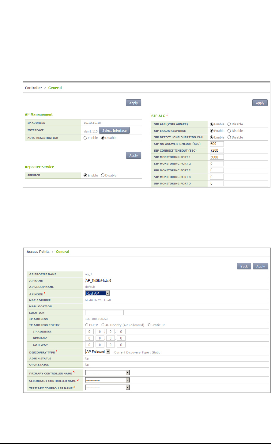
CHAPTER 5. WLAN Management
© SAMSUNG Electronics Co., Ltd. page 213 of 628
Configuration using Web UI
In the menu bar of <WEC Main window>, select <Configuration> and then select the
<Controller> <General> menu in the sub-menus. To enable repeater service, configure
the INTERFACE GROUP in the Repeater Service of the window, select Enable in the
SERVICE, and click the <Apply> button.
Figure 101. Root service management (1)
In the menu bar of <WEC Main window>, select <Configuration> and then select the
<Access Points> AP selection <General> menu in the sub-menus.
After selecting AP MODE item, click the <Apply> button and restart the AP.
Figure 102. Root service management (2)

CHAPTER 5. WLAN Management
© SAMSUNG Electronics Co., Ltd. page 214 of 628
5.1.5 MCS Configuration Management by WLAN
This is a function of configuring data rate and MCS by WLAN. You can configure MCS,
etc. by each WLAN differently because it is necessary to configure MCS, etc. differently
depending on the types of services such as FMC.
Configuration using CLI
1) Go to configure WLAN configuration mode of CLI.
WEC8500# configure terminal
WEC8500/configure# wlan 1
WEC8500/configure/wlan 1
2) Go to 80211a or 80211b depending on the bandwidth to configure.
WEC8500/configure/wlan 1# 80211a
WEC8500/configure/wlan 1/80211a#
3) Configure the data rate. The settings described as shown below can be made only
when the corresponding WLAN is set to be disabled.
WEC8500/configure/wlan 1/80211a# rate [MODE][RATE]
Parameter
Description
Mode
Mode (basic/supported)
- Basic: Basic rate supported for a terminal to access to an AP.
- Supported: A connected terminal that supports the supported
rate can communicate with an AP at the supported rate.
RATE
Data rate
- Range for 80211a: 6, 9, 12, 18, 24, 36, 48, or 54 Mbps
- Range for 80211b: 1, 2, 5.5, 6, 9, 11, 12, 18, 24, 36, 48, or 54
Mbps
4) Configure the 802.11n Modulation and Coding Scheme (MCS) rate.
WEC8500/configure/wlan 1/80211a# mcs-11n [RATE]
Parameter
Description
RATE
MSC rate (Range: 0~23)

CHAPTER 5. WLAN Management
© SAMSUNG Electronics Co., Ltd. page 215 of 628
5) Configure the 802.11ac Modulation and Coding Scheme (MCS) rate. Only 5G
bandwidth for 802.11ac MCS is configurable.
WEC8500/configure/wlan 1/80211a# mcs-11ac num-ss 2/3
enter the maximum MCS(7~9) for 1 spatial stream(s): 7
the maximum MCS : 7
enter the maximum MCS(7~9) for 2 spatial stream(s): 7
the maximum MCS : 7
enter the maximum MCS(7~9) for 3 spatial stream(s): 7
the maximum MCS : 7
[Wlan:1] Radio : 5GHz, number of SS: 3, max mcs : 7, 7, 7 Enable
6) You can check the configuration with the ‘show wlan detail #’ command.
WEC8500# show wlan detail 1
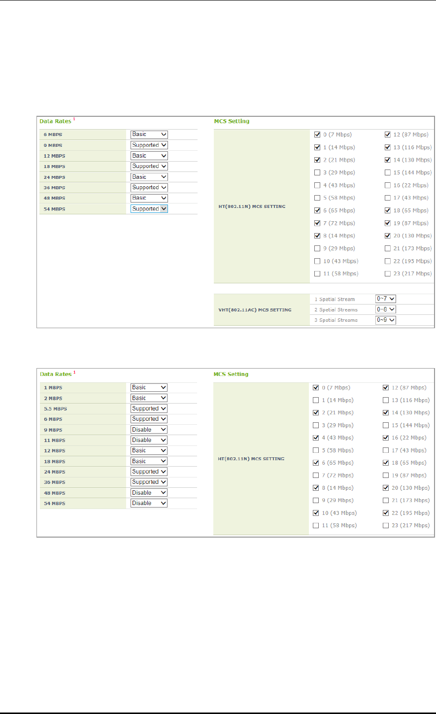
CHAPTER 5. WLAN Management
© SAMSUNG Electronics Co., Ltd. page 216 of 628
Configuration using Web UI
In the menu bar of <WEC Main window>, select <Configuration> and then select the
<WLANs> menu in the sub-menus. Select the WLAN ID to change in the WLANs screen
and move to the <802.11a/n/ac> or <802.11b/g/n> tab depending on the bandwidth.
Figure 103. MCS by WLAN: 802.11a/n/ac Configuration Management window
Figure 104. MCS by WLAN: 802.11b/g/n Configuration Management window

CHAPTER 5. WLAN Management
© SAMSUNG Electronics Co., Ltd. page 217 of 628
5.2 Local Switching
The APC provides the local switching function to support a service to an individual
network such as a branch office. The local switching function enables an AP to be
connected to WAN for external connection in an individual network where the APC is not
installed. The control packet of an AP and a wireless terminal is processed in the
centralized APC and a general data packet is processed in an individual network.
Therefore, if the tunnel mode of the WLAN is changed to local switching, part of the data
packet forwarding process performed by the APC is performed by the AP.
The following AP functions must be configured in the WLAN which is configured for local
switching:
1) WLAN-VLAN Mapping
The wireless device traffic connected to the configured local switching WLAN is
forwarded by the AP with the configured VLAN tag.
2) ACL
Packet filtering ACL is performed for the wireless device traffic connected to the
configured local switching WLAN.
3) Preauthetication ACL of Captive Portal
Web preauthentication packet forwarding ACL is processed for the wireless device
traffic connected to the local switching WLAN configured for captive portal.
The functions above are activated only for the APs added to the remote AP group.
Configuration using CLI
The procedure of local switching configuration is as follows:
1) By referring to the ‘Configuring Remote AP Group’, add an AP to a remote AP group.
2) Enter into the configure wlan configuration mode of CLI, and configure ‘tunnel-
mode’ to ‘local-bridging’.
WEC8500# configure terminal
WEC8500/configure# wlan 1
WEC8500/configure/wlan 1# tunnel-mode local-bridging
tunnel-mode local-bridging
3) Enter into the configure AP configuration mode of CLI, and configure a local Vlan
ID per WLAN.
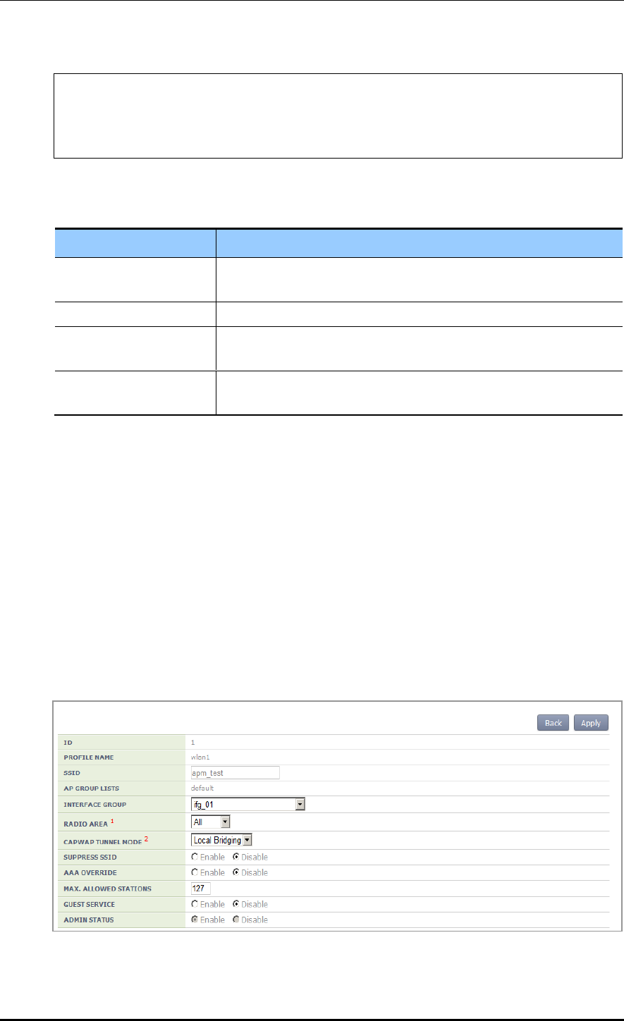
CHAPTER 5. WLAN Management
© SAMSUNG Electronics Co., Ltd. page 218 of 628
WEC8500# configure terminal
WEC8500/configure# ap ap_1
WEC8500/configure/ap ap_1# profile
WEC8500/configure/ap ap_1/profile#
local-bridging [WLAN_ID][VLAN_ID/ACL_NAME/PRE_AUTH_ACL_NAME]
Parameter
Description
WLAN_ID
WLAN ID (Range: 1-254)
(available only for WLANs the tunnel-mode of which is local-bridging)
VLAN_ID
VLAN ID (Range: 1-4094)
ACL_NAME
ACL name to configure for the WLAN service
(only for options set in IP ACL)
PRE_AUTH_ACL_NAME
ACL name to configure for pre-authentication of the WLAN
(only for options set in IP ACL)
4) Operator can check the configuration information by executing the ‘show remote-ap-
group summary’, ‘show wlan detail’, ‘show ap local-bridging [AP_PROFILE_
NAME]’ command.
Configuration using Web UI
By referring to the ‘Configuring Remote AP Group’, add an AP to a remote AP group.
In the menu bar of <WEC Main window>, select <Configuration> and then select the
<WLANs> menu in the sub-menus. Select a WLAN ID to change in the WLANs screen
and go to the <General> tab. After changing the ‘CAPWAP TUNNEL MODE’ to ‘Local
Bridging’, click the <Apply> button.
Figure 105. Local Switching Configuration Window of WLAN
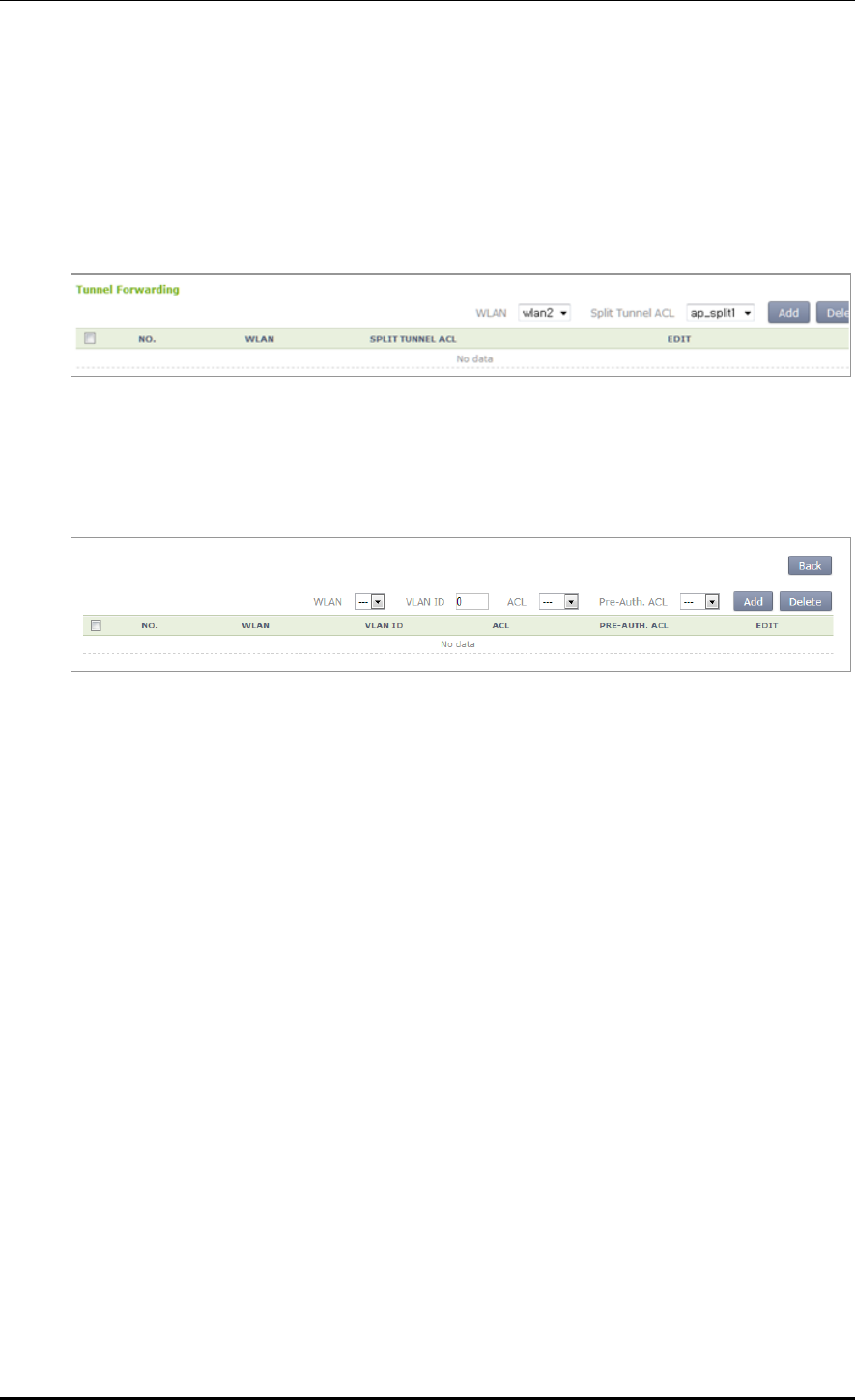
CHAPTER 5. WLAN Management
© SAMSUNG Electronics Co., Ltd. page 219 of 628
In the menu bar of <WEC Main window>, select <Configuration> and then select the
<Access Points> menu in the sub-menus. In the Access Points screen, select an AP to
change and go to the <Remote AP> tab.
Select the WLAN set with tunneling and enter the split ACL before clicking the <Add>
button.
Figure 106. Split ACL Configuration Window of WLAN Allocated to AP
Select the WLAN set with local bridging and then enter VLAN ID/ACL/Pre-Auth. ACL
before clicking the <Add> button.
Figure 107. VLAN/ACL/Pre-Auth.ACL Configuration Window of WLAN Allocated to AP

CHAPTER 5. WLAN Management
© SAMSUNG Electronics Co., Ltd. page 220 of 628
5.3 Security and Authentication
The Samsung W-EP AP/APC supports the security and authentication function defined in
the IEEE 802.11-based wireless LAN security standard and its main mechanism is as
follows:
Wired Equivalent Privacy (WEP)
Wi-Fi Protected Access Version 1 (WPA1), Wi-Fi Protected Access Version 2 (WPA2)
Authentication type: Pre-Shared Key (PSK), 802.1X
Encryption type: Temporal Key Integrity Protocol (TKIP), AES-CCMP
When a new WLAN is added, the initial WLAN security configuration becomes all
disabled. Therefore, an operator must configure the security function.
5.3.1 Initialization of WLAN Security Function
This is a procedure to disable WLAN, where the security function is configured, to the
initial status.
Configuration using CLI
An example of initializing the security function of wlan 1 is show below.
1) Go to configure wlan configuration mode of CLI.
WEC8500# configure terminal
WEC8500/configure# wlan 1
2) After entering into the security configuration mode, use the ‘setDefault’ command to
initialize the security configuration.
WEC8500/configure/wlan 1# security
WEC8500/configure/wlan 1/security# setDefault
3) After applying the changed configuration, exit the security configuration mode.
WEC8500/configure/wlan 1/security# apply
WEC8500/configure/wlan 1/security# exit
4) To check configuration information, use the ‘show wlan security summary’ command.

CHAPTER 5. WLAN Management
© SAMSUNG Electronics Co., Ltd. page 221 of 628
Configuration using Web UI
In the menu bar of <WEC Main window>, select <Configuration> and then select the
<WLANs> menu in the sub-menus. Select a WLAN ID to change in the WLANs screen
and go to the <Security> <L2> tab.
Figure 108. Initialization of WLAN security function
The configuration items available in the window are as follows.
Item
Description
PROFILE NAME
A WLAN configuration name is displayed.
L2 SECURITY TYPE
Layer2 security function type
- None: Security function disabled (Select this to initialize the
WLAN security function.)
- Static WEP: Static WEP security function
- 802.1x (Dynamic WEP): Dynamic WEP security function
- Static WEP + 802.1x (Dynamic WEP): Static/Dynamic WEP
security function
- WPA + WPA2: WPA/WPA2 PSK/802.1x security function
WPA POLICY
WPA
WPA Version 1 function is enabled when selected
ENCRYPTION
TYPE
Encryption type
- TKIP: TKIP type
- CCMP: AES-CCMP type
- Both: TKIP, AES-CCMP type
WPA2 POLICY
WPA2
The WPA Version 2 function is always enabled and cannot be
changed.
ENCRYPTION
TYPE
The only supported encryption method is CCMP and this
cannot be changed.
- CCMP: AES-CCMP method
AUTH KEY
MGMT
PSK/802.1x
Authentication key management type
- PSK: PSK (shared key) authentication type
- 802.1x: 802.1x authentication type through a RADIUS
server
PSK FORMAT
PSK key input type
- ASCII: ASCII character string
- HEX: Hexadecimal value
PSK KEY
PSK key
- 8-63 ASCII character string
- 64-characters of hexadecimal value

CHAPTER 5. WLAN Management
© SAMSUNG Electronics Co., Ltd. page 222 of 628
Item
Description
PMK LIFETIME
PMK effective time (unit: s, range: 0-1000000, default: 43200)
EAPOL REAUTHENTICATION
PERIOD
EAP re-authentication interval (unit: s, range: 0-100000,
default: 0)
STATIC WEP
WEP KEY
FORMAT
key input format
- ASCII: ASCII character string
- HEX: Hexadecimal value
WEP KEY
SIZE
Key length
- 40: 40-bit (5-byte)
- 104: 104-bit (13-byte)
STATIC WEP
WEP KEY
INDEX
Key index (1-4)
WEP KEY
key value
802.1X(DYNAM
IC WEP)
WEP KEY
SIZE
Key length
- 40: 40-bit (5-byte)
- 104: 104-bit (13-byte)
After selecting the L2 Security Type as None, click the <Apply> button.
5.3.2 WPA/WPA2 PSK Configuration
The WPA/WPA2 PSK, one of wireless LAN authentication types, can be used in a small
size network where an authentication server is not installed.
The procedure of WPA/ WPA2 PSK configuration is as follows.
Configuration using CLI
1) Go to configure wlan configuration mode of CLI.
WEC8500# configure terminal
WEC8500/configure# wlan 1
2) Go to security configuration mode and initialize the configuration.
WEC8500/configure/wlan 1# security
WEC8500/configure/wlan 1/security# setDefault
3) Configure the WPA type.
WEC8500/configure/wlan 1/security# [WPA_TYPE]

CHAPTER 5. WLAN Management
© SAMSUNG Electronics Co., Ltd. page 223 of 628
Parameter
Description
WPA_TYPE
WPA type (wpa/wpa2): WPA Version 2 must be enabled at all times.
- wpa: WPA Version 1
- wpa2: WPA Version 2
4) Configure the PSK key.
WEC8500/configure/wlan 1/security# psk [KEY_TYPE] [KEY_STRING]
Parameter
Description
KEY_TYPE
PSK key input format (ascii/hex)
- ASCII: ASCII character string
- HEX: Hexadecimal value
KEY_STRING
PSK key
5) Configure the encryption type.
WEC8500/configure/wlan 1/security# [WPA_TYPE] [ENC_TYPE]
Parameter
Description
WPA_TYPE
WPA type (wpa/wpa2): Use the same value as the WPA type
configured before. WPA Version 2 must be enabled at all times.
- wpa: WPA Version 1
- wpa2: WPA Version 2
ENC_TYPE
Encryption type (tkip/ccmp)
- tkip: TKIP type. TKIP cannot be configured for WPA Version 2.
- ccmp: AES-CCMP type
6) Configure the key management algorithm to PSK.
WEC8500/configure/wlan 1/security# keymgmt psk
7) Disable the 802.1x key management algorithm.
WEC8500/configure/wlan 1/security# no keymgmt ieee8021x
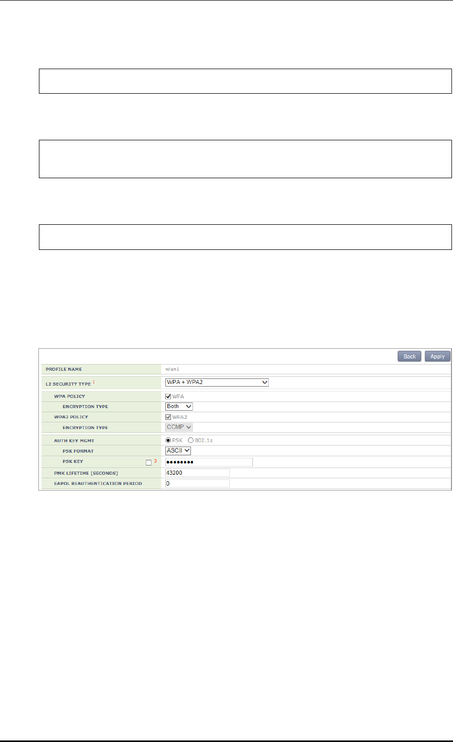
CHAPTER 5. WLAN Management
© SAMSUNG Electronics Co., Ltd. page 224 of 628
8) Disable the 802.1x authentication.
WEC8500/configure/wlan 1/security# no ieee8021x
9) After applying the changed configuration, exit the security configuration mode.
WEC8500/configure/wlan 1/security# apply
WEC8500/configure/wlan 1/security# exit
10) To check the configuration information, use the following command.
WEC8500/configure# show wlan security summary
Configuration using Web UI
In the menu bar of <WEC Main window>, select <Configuration> and then select the
<WLANs> menu in the sub-menus. Select a WLAN ID to change in the WLANs screen
and go to the <Security> <L2> tab.
Figure 109. WPA/WPA2 PSK configuration
After selecting the L2 Security Type as WPA + WPA2 and AUTH KEY MGMT as PSK,
click the <Apply> button.
For more information about detail configuration item, see ‘5.3.1 Initialization of WLAN
Security Function’.
CHAPTER 5. WLAN Management
© SAMSUNG Electronics Co., Ltd. page 225 of 628
5.3.3 WPA/WPA2 802.1x Configuration
The WPA/WPA2 802.1x, one of wireless LAN authentication types does authentication
through an authentication server such as a Remote Authentication Dial-In User Service
(RADIUS) server.
To configure WPA/WPA2 802.1x to WLAN, execute the command as follows:
As the 802.1x authentication needs interoperation with a RADIUS server, the
RADIUS server required for the WLAN security configuration must be configured
first. For more information about RADIUS server configuration, see ‘8.1 RADIUS
Server Configuration’.
Configuration using CLI
1) Go to configure wlan configuration mode of CLI.
WEC8500# configure terminal
WEC8500/configure# wlan 1
2) Go to security configuration mode and initialize the configuration.
WEC8500/configure/wlan 1# security
WEC8500/configure/wlan 1/security# setDefault
3) Configure the WPA type.
WEC8500/configure/wlan 1/security# wpa_type
Parameter
Description
wpa_type
WPA type (wpa/wpa2): WPA Version 2 must be enabled at all times.
- wpa: WPA Version 1
- wpa2: WPA Version 2
4) Configure the encryption type.
WEC8500/configure/wlan 1/security# [WPA_TYPE] [ENC_TYPE]
Parameter
Description
WPA_TYPE
WPA type (wpa/wpa2): Use the same value as the WPA type
configured before. WPA Version 2 must be enabled at all times.
- wpa: WPA Version 1
- wpa2: WPA Version 2

CHAPTER 5. WLAN Management
© SAMSUNG Electronics Co., Ltd. page 226 of 628
Parameter
Description
ENC_TYPE
Encryption type (tkip/ ccmp)
- tkip: TKIP type. TKIP cannot be configured for WPA Version 2.
- ccmp: AES-CCMP type
5) Disable the PSK key management algorithm.
WEC8500/configure/wlan 1/security# no keymgmt psk
6) Configure the key management algorithm to 802.1x.
WEC8500/configure/wlan 1/security# keymgmt ieee8021x
7) Enable the 802.1x authentication.
WEC8500/configure/wlan 1/security# ieee8021x
8) After enabling the RADIUS server function for authentication, specify the index of
authentication RADIUS server. The RADIUS server information must be configured
in advance.
WEC8500/configure/wlan 1/security# radius-server auth-servers
[RADIUS_SERVER_ID_LIST]
Parameter
Description
RADIUS_SERVER_ID_LIST
RADIUS server ID list (Up to 3 IDs can be configured.)
9) After enabling the RADIUS server function for accounting, specify the index of
account RADIUS server. The RADIUS server information must be configured in
advance.
WEC8500/configure/wlan 1/security# radius-server acct-servers
[RADIUS_SERVER_ID_LIST]
Parameter
Description
RADIUS_SERVER_ID_LIST
RADIUS server ID list (Up to 3 IDs can be configured.)
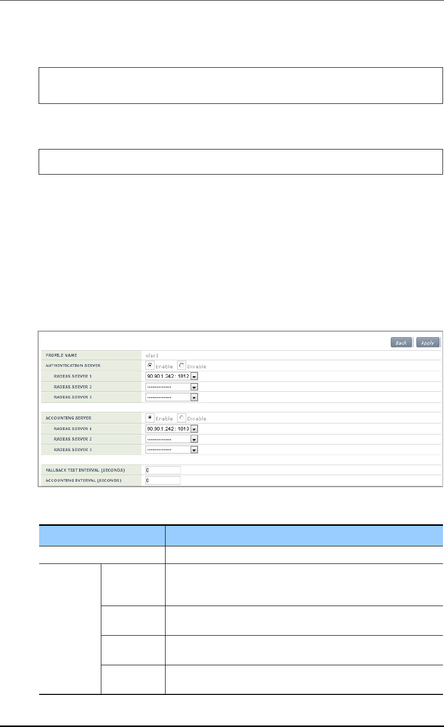
CHAPTER 5. WLAN Management
© SAMSUNG Electronics Co., Ltd. page 227 of 628
10) After applying the changed configuration, exit the security configuration mode.
WEC8500/configure/wlan 1/security# apply
WEC8500/configure/wlan 1/security# exit
11) To check the configuration information, use the following command.
WEC8500/configure# show wlan security summary
12) To check configuration information, use the ‘show wlan security summary’ command.
Configuration using Web UI
In the menu bar of <WEC Main window>, select <Configuration> and then select the
<WLANs> menu in the sub-menus.
1) Select a WLAN ID to change in the WLANs screen and go to the <Security>
<Radius> tab.
Figure 110. WPA/WPA2 802.1x Configuration (1)
Item
Description
PROFILE NAME
A WLAN configuration name is displayed.
AUTHENTIC
ATION
SERVER
Enable/
Disable
Whether the authentication function is enabled.
- Enable: The authentication function is enabled.
- Disable: The authentication function is disabled.
RADIUS
SERVER 1
Authentication server that will be used as the first priority
(Can select one out of pre-configured RADIUS servers.)
RADIUS
SERVER 2
Authentication server that will be used as the second priority
(Can select one out of pre-configured RADIUS servers.)
RADIUS
SERVER 3
Authentication server that will be used as the third priority
(Can select one out of pre-configured RADIUS servers.)
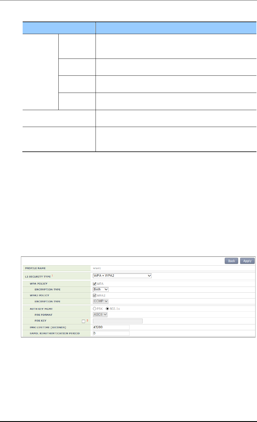
CHAPTER 5. WLAN Management
© SAMSUNG Electronics Co., Ltd. page 228 of 628
Item
Description
ACCOUNTI
NG
SERVER
Enable/
Disable
Whether the accounting function is enabled.
- Enable: The accounting function is enabled.
- Disable: The accounting function is disabled.
RADIUS
SERVER 1
Accounting server that will be used as the first priority
(Can select one out of pre-configured RADIUS servers.)
RADIUS
SERVER 2
Accounting server that will be used as the second priority
(Can select one out of pre-configured RADIUS servers.)
RADIUS
SERVER 3
Accounting server that will be used as the third priority
(Can select one out of pre-configured RADIUS servers.)
FALLBACK TEST
INTERVAL
RADIUS server Fallback attempt interval (unit: s, range: 0-500,
default: 0), When set to 0, the fallback function is disabled.
ACCOUNTING INTERVAL
Accounting information transmission interval (unit: s, range: 0-
10000, default: 600), When set to 0, the periodic accounting
information transmission function is disabled.
Select AUTHENTICATION SERVER and ACCOUNTING SERVER as Enable and
configure the rest items.
Internal RADIUS Server
Operator can use a RADIUS server in the APC. The internal RADIUS server only
supports the authentication function and does not support the accounting or aaa-
override, etc. To use an internal RADIUS server, select ‘Internal’ when selecting a
RADIUS server during authentication server configuration.
2) Click the <L2> tab.
Figure 111. WPA/WPA2 802.1x Configuration (2)
Select the L2 Security Type as WPA + WPA2 and AUTH KEY MGMT as 802.1x.
After configuring the rest values as required, click the <Apply> button.
For more information about detail configuration item of L2 tab, see ‘5.3.1
Initialization of WLAN Security Function’.

CHAPTER 5. WLAN Management
© SAMSUNG Electronics Co., Ltd. page 229 of 628
5.3.4 Static WEP Configuration
The WEP is a security algorithm defined in the initial wireless LAN standard.
It provides security by using a cryptographic key and Initial Vector (IV) to encrypt the
wireless transmission data exchanged between an AP and a wireless terminal connected to
a wireless LAN.
Configuration using CLI
For static WEP configuration, execute the following commands.
1) Go to configure wlan configuration mode of CLI.
WEC8500# configure terminal
WEC8500/configure# wlan 1
2) Go to security configuration mode and initialize the configuration.
WEC8500/configure/wlan 1# security
WEC8500/configure/wlan 1/security# setDefault
3) Disable WPA1, WPA2, and 802.1x authentication.
WEC8500/configure/wlan 1/security# no wpa
WEC8500/configure/wlan 1/security# no wpa2
WEC8500/configure/wlan 1/security# no ieee8021x
4) Enable the WEP.
WEC8500/configure/wlan 1/security# wep
5) Configure the WEP Shared Key mode.
WEC8500/configure/wlan 1/security# wep shared
6) Use the following command to configure the cryptographic key of WEP.
WEC8500/configure/wlan 1/security# wep encryption [KEY_TYPE]
[KEY_STRING] [KEY_INDEX] [KEY_LENGTH]
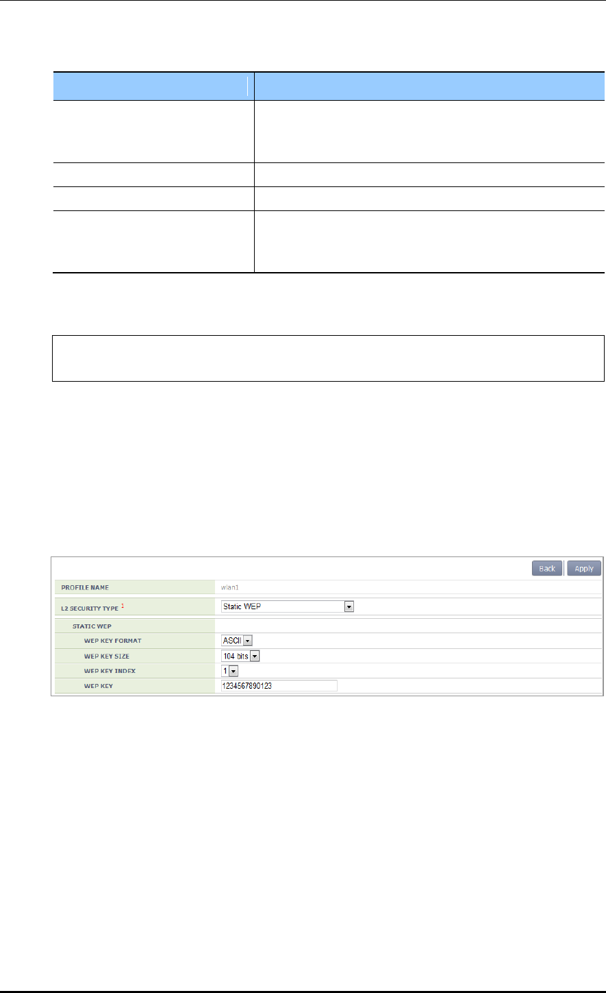
CHAPTER 5. WLAN Management
© SAMSUNG Electronics Co., Ltd. page 230 of 628
Parameter
Description
KEY_TYPE
WEP key Input format of WEP cryptographic key (ascii/hex)
- ASCII: ASCII character string
- HEX: Hexadecimal value
KEY STRING
WEP cryptographic key
KEY_INDEX
Key index (range: 1-4)
KEY_LENGTH
Key length (Bit unit)
- 40
- 104
7) After applying the changed configuration, exit the security configuration mode.
WEC8500/configure/wlan 1/security# apply
WEC8500/configure/wlan 1/security# exit
8) To check configuration information, use the ‘show wlan security summary’ command.
Configuration using Web UI
In the menu bar of <WEC Main window>, select <Configuration> and then select the
<WLANs> menu in the sub-menus. Select a WLAN ID to change in the WLANs screen
and go to the <Security> <L2> tab.
Figure 112. Static WEP configuration
Select the L2 Security Type as Static WEP. After configuring the rest values as required,
click the <Apply> button.
For more information about detail configuration item of L2 tab, see ‘5.3.1 Initialization of
WLAN Security Function’.

CHAPTER 5. WLAN Management
© SAMSUNG Electronics Co., Ltd. page 231 of 628
5.3.5 Dynamic WEP Configuration
The Dynamic WEP is a security algorithm that improves the security vulnerabilities of a
static WEP by using 802.1x authentication. Unlike the static WEP that is based on a
configured fixed key, it creates a cryptographic key by executing 802.1x authentication
when a terminal is connected.
Configuration using CLI
For dynamic WEP configuration, execute the command as follows:
1) Go to configure wlan configuration mode of CLI.
WEC8500# configure terminal
WEC8500/configure# wlan 1
2) Go to security configuration mode and initialize the configuration.
WEC8500/configure/wlan 1# security
WEC8500/configure/wlan 1/security# setDefault
3) Enable the 802.1x authentication.
WEC8500/configure/wlan 1/security# ieee8021x
4) To configure the length of a cryptographic key of dynamic WEP, execute the following
command.
WEC8500/configure/wlan 1/security# ieee8021x encryption [KEY_LENGTH]
Parameter
Description
KEY_LENGTH
Key length (Bit unit)
- 40
- 104
5) After enabling the RADIUS server function for authentication, specify the index of
authentication RADIUS server. The RADIUS server information must be configured
in advance.
WEC8500/configure/wlan 1/security# radius-server auth-servers
[RADIUS_SERVER_ID_LIST]

CHAPTER 5. WLAN Management
© SAMSUNG Electronics Co., Ltd. page 232 of 628
Parameter
Description
RADIUS_SERVER_ID_LIST
RADIUS server ID list (Up to 3 IDs can be configured.)
6) After enabling the RADIUS server function for accounting, specify the index of
account RADIUS server. The RADIUS server information must be configured in
advance.
WEC8500/configure/wlan 1/security# radius-server acct-servers
[RADIUS_SERVER_ID_LIST]
Parameter
Description
RADIUS_SERVER_ID_LIST
RADIUS server ID list (Up to 3 IDs can be configured.)
7) After applying the changed configuration, exit the security configuration mode.
WEC8500/configure/wlan 1/security# apply
WEC8500/configure/wlan 1/security# exit
8) To check the configuration information, execute the following command.
WEC8500/configure# show wlan security summary
9) To check configuration information, execute the ‘show wlan security summary’
command.

CHAPTER 5. WLAN Management
© SAMSUNG Electronics Co., Ltd. page 233 of 628
Configuration using Web UI
In the menu bar of <WEC Main window>, select <Configuration> and then select the
<WLANs> menu in the sub-menus.
1) Select a WLAN ID to change in the WLANs screen and go to the <Security>
<Radius> tab. For details about configuration, refer to the section 5.3.3.
2) Click the <L2> tab.
Figure 113. Dynamic WEP Configuration Window
Select the L2 Security Type as Dynamic WEP. After configuring the rest values as
required, click the <Apply> button.
For more information about detail configuration item of L2 tab, see ‘5.3.1
Initialization of WLAN Security Function’.
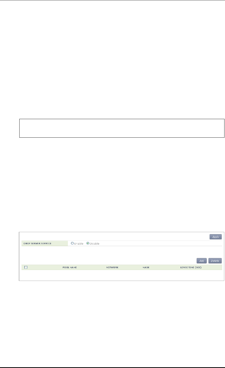
CHAPTER 5. WLAN Management
© SAMSUNG Electronics Co., Ltd. page 234 of 628
5.4 DHCP Configuration
The DHCP service of APC consists of DHCP server, DHCP relay, and DHCP proxy.
5.4.1 DHCP Server
5.4.1.1 DHCP Server Configuration
A DHCP server in the APC dynamically allocates an IP address to a client.
Configuration using CLI
1) Go to configure mode of CLI.
WEC8500# configure terminal
WEC8500/configure #
2) To enable or disable the DHCP server, enter the ‘ip dhcp’ command. Use ‘no’ in front
of the command to disable the configuration.
ip dhcp enable
no ip dhcp enable
3) To check configuration information, use the ‘show ip dhcp’ command.
Configuration using Web UI
In the menu bar of <WEC Main window>, select <Configuration> and then select the
<DHCP> <Internal Server> menu in the sub-menus.
Figure 114. DHCP server configuration
Enable/Disable the DHCP SERVER SERVICE item in the Internal Server window to
enable or disable a DHCP server.

CHAPTER 5. WLAN Management
© SAMSUNG Electronics Co., Ltd. page 235 of 628
5.4.1.2 DHCP Pool
The DHCP pool includes the range of IP address to be allocated to a client, DNS server that
will be used by a DHCP client, NTP server, and default router IP address information, etc.
Configuration using CLI
[Pool Creation]
The procedure of creating a pool in an internal DHCP server and entering into the pool
mode is as follows:
1) Go to configure mode of CLI.
WEC8500# configure terminal
WEC8500/configure #
2) Enter the ‘ip dhcp pool’ command. Use ‘no’ in front of the command to delete a DHCP
pool.
ip dhcp pool [POOL_NAME]
no ip dhcp pool [POOL_NAME]
3) To check configuration information, use the ‘show ip dhcp’ command.
To configure the DHCP Pool related function, execute the command as follows to go
to the DHCP pool mode.
WEC8500# configure terminal
WEC8500/configure # ip dhcp pool test
WEC8500/configure/ip/dhcp/pool test#
[Configuring IP address]
Before configuring a DHCP pool, you should configure a network first. If the network is
not configured, you cannot execute other commands.
Enter the command as follows to configure the network bandwidth of a DHCP pool to
serve. Enter ‘no’ parameter to delete a configured network bandwidth. After entering a
separator ‘/’ after an IP address, enter the length of a netmask address or enter a netmask
address after the IP address.
network [IP_ADDRESS] [NETMASK]
network [IP_ADDRESS]/[LENGTH]
no network

CHAPTER 5. WLAN Management
© SAMSUNG Electronics Co., Ltd. page 236 of 628
Parameter
Description
IP_ADDRESS
IP address
NETMASK
Netmask address
LENGTH
Netmask length
[Configuring Gateway]
This command configures the gateway address of a DHCP client. Enter ‘no’ parameter to
delete a configured address.
default-router [IP_ADDRESS]
no default-router
Parameter
Description
IP_ADDRESS
Gateway IP address
[Configuring DNS Server]
Up to 3 IP addresses can be configured for a DNS server. Enter ‘no’ parameter to delete a
configured DNS server. The lower command ‘all’ is used to delete all the IP addresses of a
configured DNS server.
dns-server [IP_ADDRESS]
no dns-server [IP_ADDRESS]
no dns-server all
Parameter
Description
IP_ADDRESS
DNS Server’s IP address
[Configuring Domain Name]
This command configures or deletes a domain name.
domain-name [DOMAIN]
no domain-name [DOMAIN]
Parameter
Description
DOMAIN
Domain name to configure (e.g. samsung APC.co.kr)

CHAPTER 5. WLAN Management
© SAMSUNG Electronics Co., Ltd. page 237 of 628
[Configuring Fixed IP Address to MAC Address]
This command configures a fixed IP address to a specific MAC address or deletes the
configuration.
The ‘range’ of IP address to configure cannot be overlapped with the IP range and
maximum 255 IP addresses can be configured. In addition, use the ‘no fix-address all’
command to delete all the configured values.
fix-address [aa:bb:cc:dd:ee:ff A.B.C.D]
no fix-address [aa:bb:cc:dd:ee:ff A.B.C.D]
fix-address all
As shown in the below example, 100.100.100.10 can be always allocated to the IP address
of a wireless terminal whose MAC address is 11:22:33:44:55:66.
WEC8500/configure/ip/dhcp/pool test# fix-address 11:22:33:44:55:66
100.100.100.10
[Configuring IP Address Lease Time]
Configure the time when a wireless terminal receives an IP address. The ‘lease infinite’
command configures the time infinitely. If ‘no’ parameter is entered in front of the
command, it is configured to 24 hours (default).
lease [TIME]
lease infinite
no lease
Parameter
Description
TIME
Lease time (range: 120-8640000, Unit: s)
[Configuring NTP Server]
Up to 3 IP addresses of a NTP server can be configured or deleted. In addition, use the ‘no
ntp-server all’ command to delete all the configured addresses of a NTP server.
ntp-server [IP_ADDRESS]
no ntp-server [IP_ADDRESS]
no ntp-server all
Parameter
Description
IP_ADDRESS
The IP address of the NTP server

CHAPTER 5. WLAN Management
© SAMSUNG Electronics Co., Ltd. page 238 of 628
[Ping check]
When a DHCP server allocates an IP address to a client, ping check can be used to check if
an IP address to allocate is being used in the current network.
ping-check [enable/disable]
Parameter
Description
enable/disable
Configures whether to use ping check (default: disable)
[Configuring IP Address Range]
A DHCP server configures the range of IP address to allocate to a client. The range of IP
address to add is up to 16 and the IP address specified in the range cannot be duplicated
with the IP address of fix-address. Enter ‘no’ to delete the range of configured IP address
and enter ‘no range all’ to delete all the ranges.
range [IP_ADDRESS]
range [IP_ADDRESS1] [IP_ADDRESS2]
no range [IP_ADDRESS]
no range [IP_ADDRESS1] [IP_ADDRESS2]
no range all
Parameter
Description
IP_ADDRESS
IP address. Use to configure one IP address.
IP_ADDRESS1
Start address of IP address range
IP_ADDRESS2
Last address of IP address range
[Capwap Access Controller Address Configuration]
Up to three IP addresses for a Capwap controller can be configured or deleted. Also, all
Capwap controller addresses can be deleted using the ‘no capwap-dhcp-option’ command.
capwap-dhcp-option [IP_ADDRESS]
no capwap-dhcp-option
Parameter
Description
IP_ADDRESS
IP address of the Capwap Controller
[Configuring Option Data]
Use the ‘user-option’ command to configure or delete the DHCP option. Use ‘no’ to delete
each option and use ‘no user-option all’ to delete all the options.
Option: Up to 254 can be entered (1-254).
Data type: string (character string), octet (hex string), int (32 bit integer), uint (32-bit
unsigned integer), int16 (16-bit integer), uint16 (16-bit unsigned integer), ipaddress (IP
address)

CHAPTER 5. WLAN Management
© SAMSUNG Electronics Co., Ltd. page 239 of 628
Mode: Can be configured to the active/passive mode.
active: Although a client does not request data transmission, the DHCP server
transmits user-option data (Default).
passive: The DHCP server transmits data upon a client’s request.
Command
Description
- user-option [1-254] string [string] [active/passive]
- user-option [1-254] octet aa:bb:cc [active/passive]
- user-option [1-254] int [integer] [active/passive]
- user-option [1-254] uint [unsigned integer] [active/passive]
- user-option [1-254] int16 [16 bit integer] [active/passive]
- user-option [1-254] uint16 [16 bit unsigned integer]
[active/passive]
- user-option [1-254] ipaddress A.B.C.D [active/passive]
Configures an option.
- no user-option [1-254] string [string] [active/passive]
- no user-option [1-254] octet aa:bb:cc [active/passive]
- no user-option [1-254] int [integer] [active/passive]
- no user-option [1-254] uint [unsigned integer] [active/passive]
- no user-option [1-254] int16 [16 bit integer] [active/passive]
- no user-option [1-254] uint16 [16 bit unsigned integer]
[active/passive]
- no user-option [1-254] ipaddress A.B.C.D [active/passive]
Deletes a configured option.
no user-option all
Deletes all the configured
options.
A usage example is given below.
WEC8500/configure/ip/dhcp/pool test# user-option 3 string “hi, there”
active
WEC8500/configure/ip/dhcp/pool test# user-option 200 octet
33:4A:5C:6F:DD passive
WEC8500/configure/ip/dhcp/pool test# user-option 201 int -3000
WEC8500/configure/ip/dhcp/pool test# user-option 202 uint16 300
WEC8500/configure/ip/dhcp/pool test# user-option 203 ipaddress
111.22.22.33
[Retrieving Pool Information]
To check the entire information of a DHCP pool, execute the ‘show ip dhcp pool’ command.
If you enter a pool name as a parameter as shown in ‘show ip dhcp pool [POOL NAME]’,
you can check the information of a specific pool.
[Retrieving DHCP Lease Information]
To check the DHCP lease information, execute the ‘show ip dhcp lease’ command.
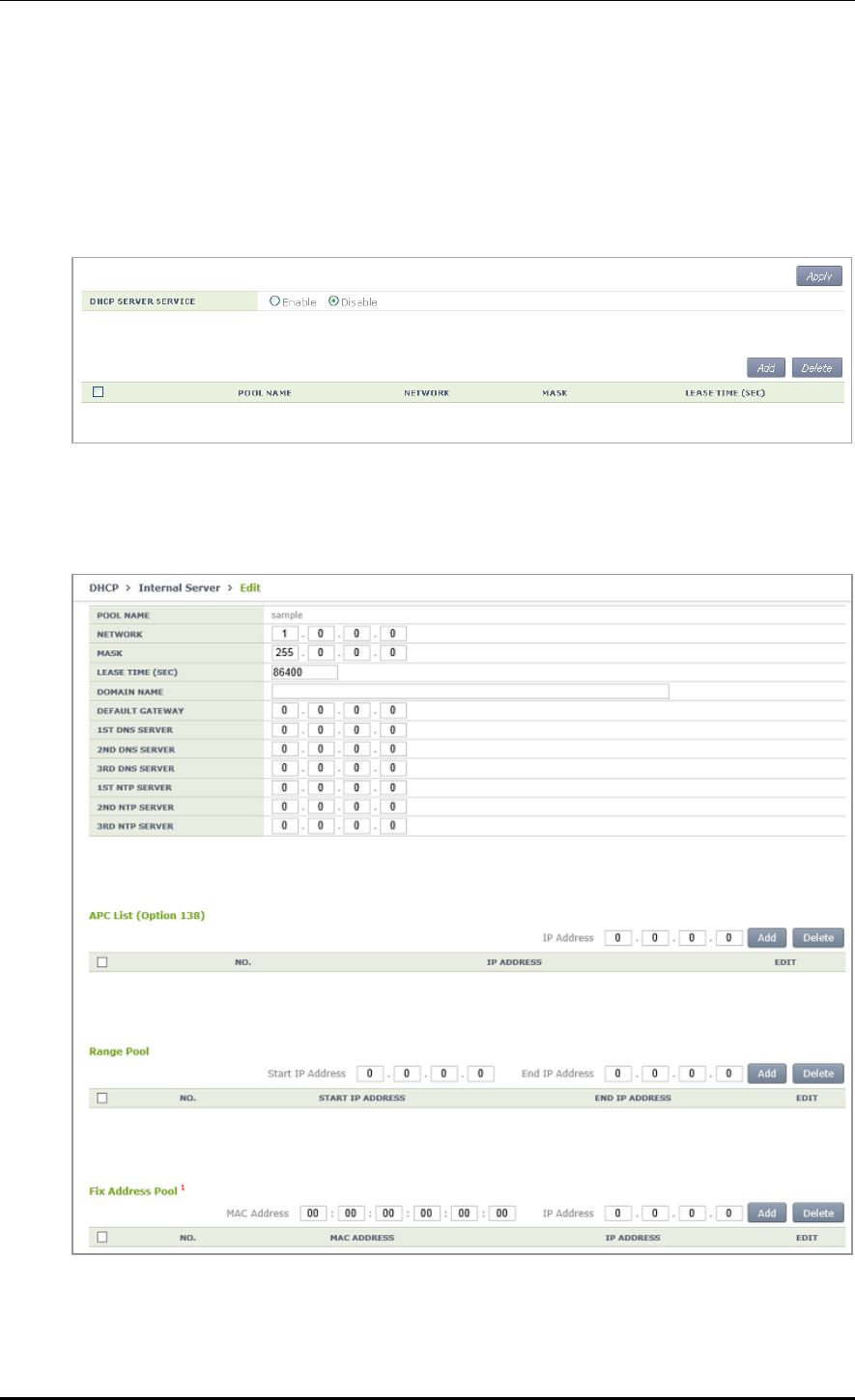
CHAPTER 5. WLAN Management
© SAMSUNG Electronics Co., Ltd. page 240 of 628
Configuration using Web UI
In the menu bar of <WEC Main window>, select <Configuration> and then select the
<DHCP> <Internal Server> menu in the sub-menus.
Click the <Add> or <Delete> button to add or delete a DHCP pool.
Figure 115. DHCP Pool (1)
The window where a DHCP pool can be added is shown below.
Figure 116. DHCP Pool (2)

CHAPTER 5. WLAN Management
© SAMSUNG Electronics Co., Ltd. page 241 of 628
POOL NAME: DHCP pool name (mandatory input item)
NETWORK: Network bandwidth IP that a DHCP server will serve (mandatory input
item)
MASK: Netmask length IP of an IP that is entered into the NETWORK item
(mandatory input item)
LEASE TIME: DHCP IP address lease time (Unit: s, default: 3600 s, Maximum value:
8640000 s)
DOMAIN NAME: Configures a domain name that will be used by a DHCP client in a
DNS.
DEFAULT GATEWAY: Gateway IP that will be configured by a DHCP client
1ST/2ND/3RD DNS SERVER: Configures a DNS server that will be used by a DHCP
client.
1ST/2ND/3RD NTP SERVER: Configures a NTP server that will be used by a DHCP
client.
APC List (Option 138): Configures APL list value corresponding to DHCP user option
#138.
Range Pool: Configures the range of IP address that will be leased to a DHCP client.
Enter an IP address into the Start IP Address IP box and End Ip Address IP box each
and then click the <Add> button to create a list. In addition, select one in the created
list and click the <Delete> button to delete it. The IP address range cannot be
overlapped with the IP address in a network bandwidth and also the IP address fixed to
a MAC address.
Fixed Address Pool: Configures a fixed IP address to the MAC address of a specific
DHCP client.
Enter a MAC address and an IP address and click the <Add> button to create the list.
In addition, select one in the created list and click the <Delete> button to delete it.
The IP address fixed to a MAC address cannot be overlapped with the IP address in a
network bandwidth and also the IP address range.
5.4.1.3 Retrieving Number of DHCP Packets
To check the number of DHCP packets that the DHCP server receives, execute the ‘show ip
dhcp statistics’ command.
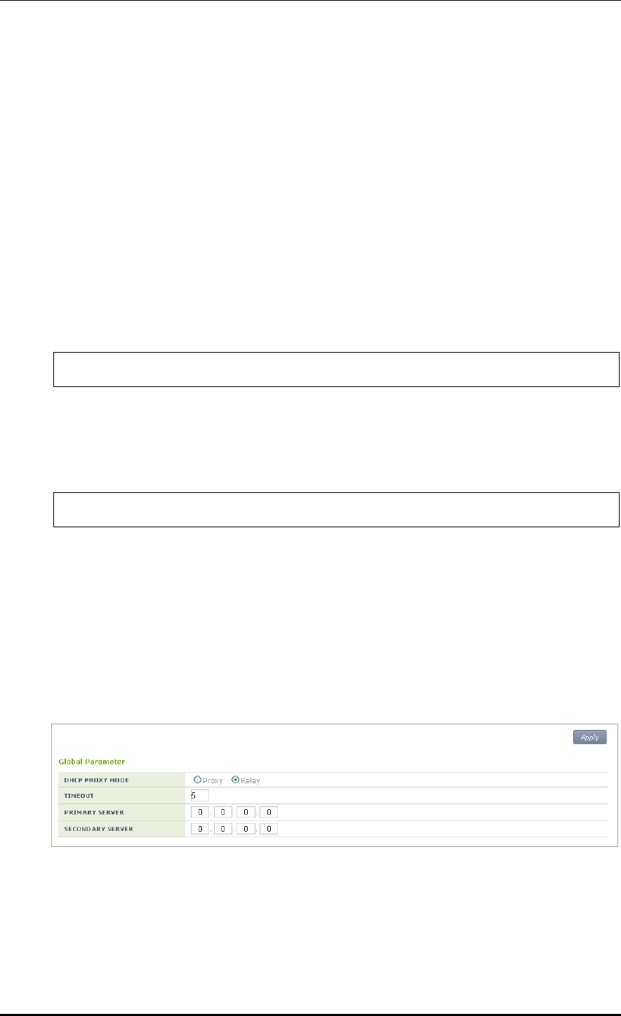
CHAPTER 5. WLAN Management
© SAMSUNG Electronics Co., Ltd. page 242 of 628
5.4.2 DHCP Relay
The DHCP relay forwards a DHCP packet received from a client through broadcast to the
DHCP server. Because it switches with the DHCP proxy, the DHCP relay is enabled when
the DHCP proxy is disabled.
The DHCP relay is working in the unit of interface. It is disabled in the ‘mgmt0’ and ‘lo’
interface. The DHCP relay is not working even when no IP address is configured in the
interface.
Configuration using CLI
The procedure of changing to the DHCP relay is as follows:
1) Go to configure mode of CLI.
WEC8500# configure terminal
2) Switch to the DHCP relay.
The relay and proxy are operating in the switching mode. If a proxy is not used, it is
operating in the relay mode.
WEC8500/configure # no ip dhcp-proxy enable
3) To check the configured DHCP information, use the ‘show ip dhcp-proxy’ command.
Configuration using Web UI
In the menu bar of <WEC Main window>, select <Configuration> and then select the
<DHCP> <Proxy> menu in the sub-menus.
You can configure the Proxy mode of DHCP to relay/proxy. Change the radio box for
configuration in the DHCP PROXY MODE of Global Parameter item.
Figure 117. DHCP Relay
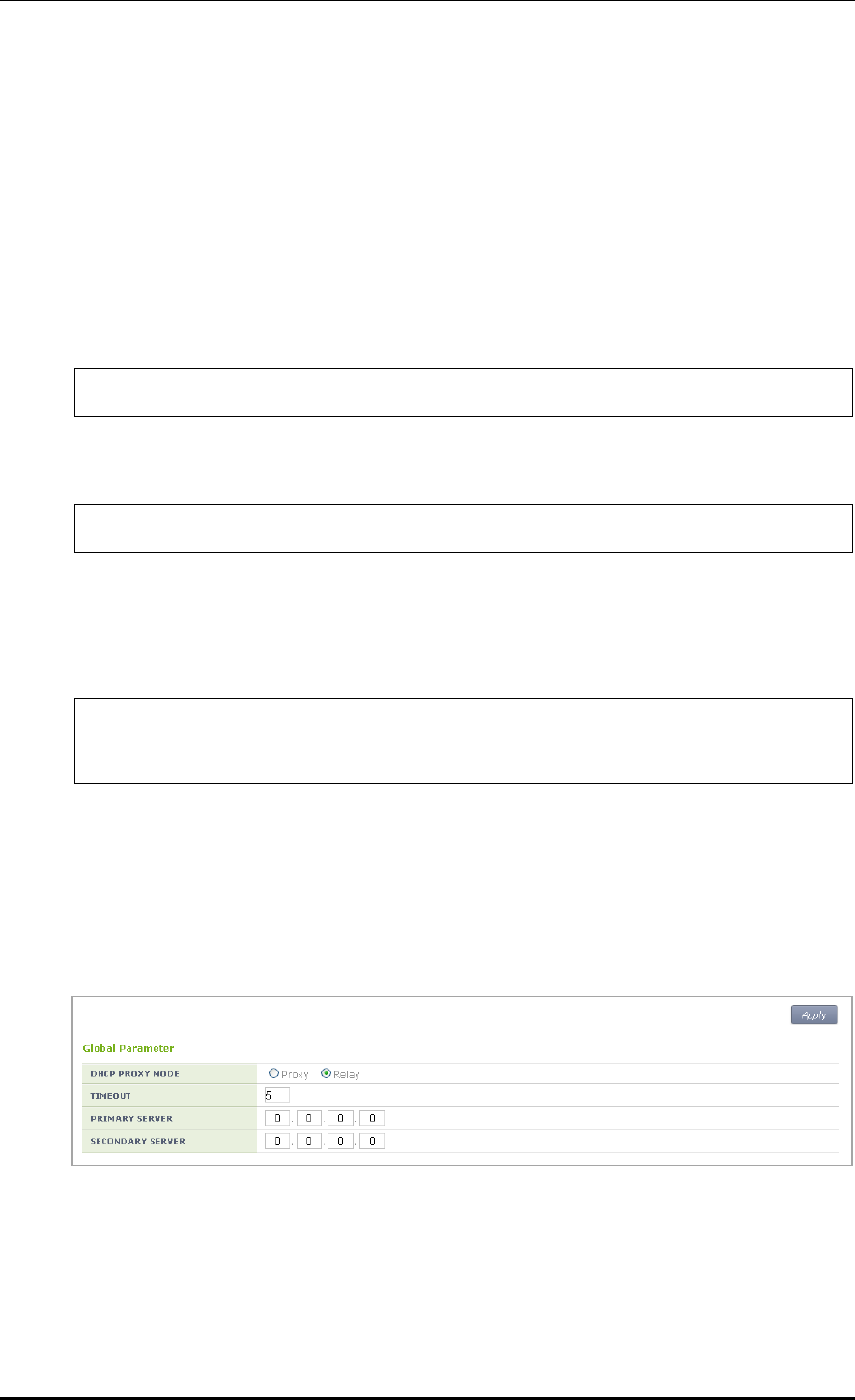
CHAPTER 5. WLAN Management
© SAMSUNG Electronics Co., Ltd. page 243 of 628
5.4.3 DHCP Proxy
The procedure of changing to the DHCP proxy is as follows.
Configuration using CLI
The CLI configuring a DHCP proxy is located as a command under ‘ip dhcp-proxy’ in the
configure mode.
1) Go to configure mode of CLI.
WEC8500# configure terminal
2) Switch to the DHCP proxy.
WEC8500/configure#ip dhcp-proxy enable
3) To check the configured information, use the ‘show ip dhcp-proxy’ command.
4) Use the below command to check an IP address that is leased through the DHCP proxy.
WEC8500t#show ip dhcp proxy-lease
IP address | Server IP | MAC address | Lease Expiration time
10.10.10.100 1.1.1.1 00:1c:bf:c1:50:28 2012/08/31 12:00:24
Configuration using Web UI
In the menu bar of <WEC Main window>, select <Configuration> and then select the
<DHCP> <Proxy> menu in the sub-menus.
You can configure the Proxy mode of DHCP to relay/proxy. Change the radio box for
configuration in the DHCP PROXY MODE of Global Parameter item.
Figure 118. DHCP Proxy

CHAPTER 5. WLAN Management
© SAMSUNG Electronics Co., Ltd. page 244 of 628
5.4.4 Option 82 Configuration
The APC uses the DHCP Option 82 to provide various services during IP allocation by
forwarding the information such as access control, QoS, or security policy, etc. when a
wireless terminal connected to an AP receives an IP address.
The Option 82 has two fields, i.e. remote ID and circuit ID. Enter the name of an interface
for which the APC constantly does relay/proxy in the circuit ID and enter a part of AP
information in the remote ID accordingly. One of the following three data can be used as
the remote id of Option 82.
ap-mac: 802.11 MAC data of the AP. The length is 12-byte (Default).
ap-mac-ssid: The character string of SSID is added to the data of AP-MAC. The length
is variable.
ap-mac-ssid: Ethernet MAC data of the AP. The length is 12-byte.
To configure Option 82 related functions, go to the interface mode by executing the
following command.
WEC8500# configure terminal
WEC8500/configure#interface vlan10
WEC8500/configure/interface vlan10#
Configuration using CLI
[Configuring Option 82]
This command enables or disables the Option 82 function. It can be configured for each
interface.
dhcp option-82 [MODE]
Parameter
Description
MODE
Configures whether to use the Option 82 function (enable/disable).
[Configuring Remote ID]
The command is shown below.
dhcp option-82 remote-id [MODE]
Parameter
Description
MODE
Specifies one out of the following three data to the Option 82 remote-id.
- ap-mac: MAC address of an AP
- ap-mac-ssid: MAC address and SSID of an AP
- ap- ethermac: Ethernet MAC address of an AP
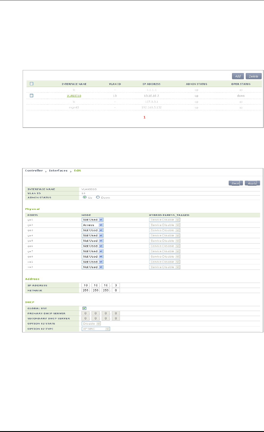
CHAPTER 5. WLAN Management
© SAMSUNG Electronics Co., Ltd. page 245 of 628
Configuration using Web UI
In the menu bar of <WEC Main window>, select <Configuration> and then select the
<Controller> <Interfaces> menu in the sub-menus. In the interface, you can see the
page where you can change the Option 82.
Figure 119. Option 82 configuration (1)
Select an item in the list and perform detail configuration.
Figure 120. Option 82 configuration (2)
After unchecking the GLOBAL USE check box in the DHCP part, configure OPTION 82
STATE and OPTION 82 TYPE and then click the <Apply> button.
In the OPTION 82 STATE, configure Enable/Disable for Option 82 and configure ap-mac,
ap-mac-ssid, or ap-ethermac for OPTION 82 TYPE.

CHAPTER 5. WLAN Management
© SAMSUNG Electronics Co., Ltd. page 246 of 628
5.4.5 Primary/Secondary Server Configuration
The DHCP relay/proxy can transmit a DHCP packet received from a client through
broadcast to maximum two DHCP servers. Here, the two servers are called a primary server
and a secondary server.
The configuration of primary/secondary servers can be done in the interface mode, but it is
also possible in the global mode. If the configuration exists both in the interface mode and
global mode, the configuration in the interface mode has a higher priority.
Configuration using CLI
[Configuration at Interface]
1) Go to configure interface mode of CLI.
WEC8500# configure terminal
WEC8500/configure#interface [INTERFACE_NAME]
2) Enter the ‘dhcp server’ command.
To configure only a primary server, do not enter the information of a secondary server.
dhcp server primary A.B.C.D secondary A.B.C.D: Configures both primary/
secondary servers.
dhcp server primary A.B.C.D: Configures only a primary server.
no dhcp server primary A.B.C.D secondary A.B.C.D: Deletes both primary/
secondary servers.
no dhcp server primary A.B.C.D: Deletes a primary server.
[Configuration at Global]
1) Go to configure mode of CLI.
WEC8500# configure terminal
WEC8500/configure#
2) Enter the ‘ip dhcp-proxy default-dhcp-server’ command.
To configure only a primary server, do not enter the information of a secondary server.
ip dhcp-proxy default-dhcp-server primary A.B.C.D secondary A.B.C.D: Configures
both global primary/secondary servers.
ip dhcp-proxy default-dhcp-server primary A.B.C.D: Configures only a global
primary server.
no ip dhcp-proxy default-dhcp-server primary A.B.C.D secondary A.B.C.D: Deletes
both global primary/secondary servers.
no ip dhcp-proxy default-dhcp-server primary A.B.C.D: Deletes a global primary
server.
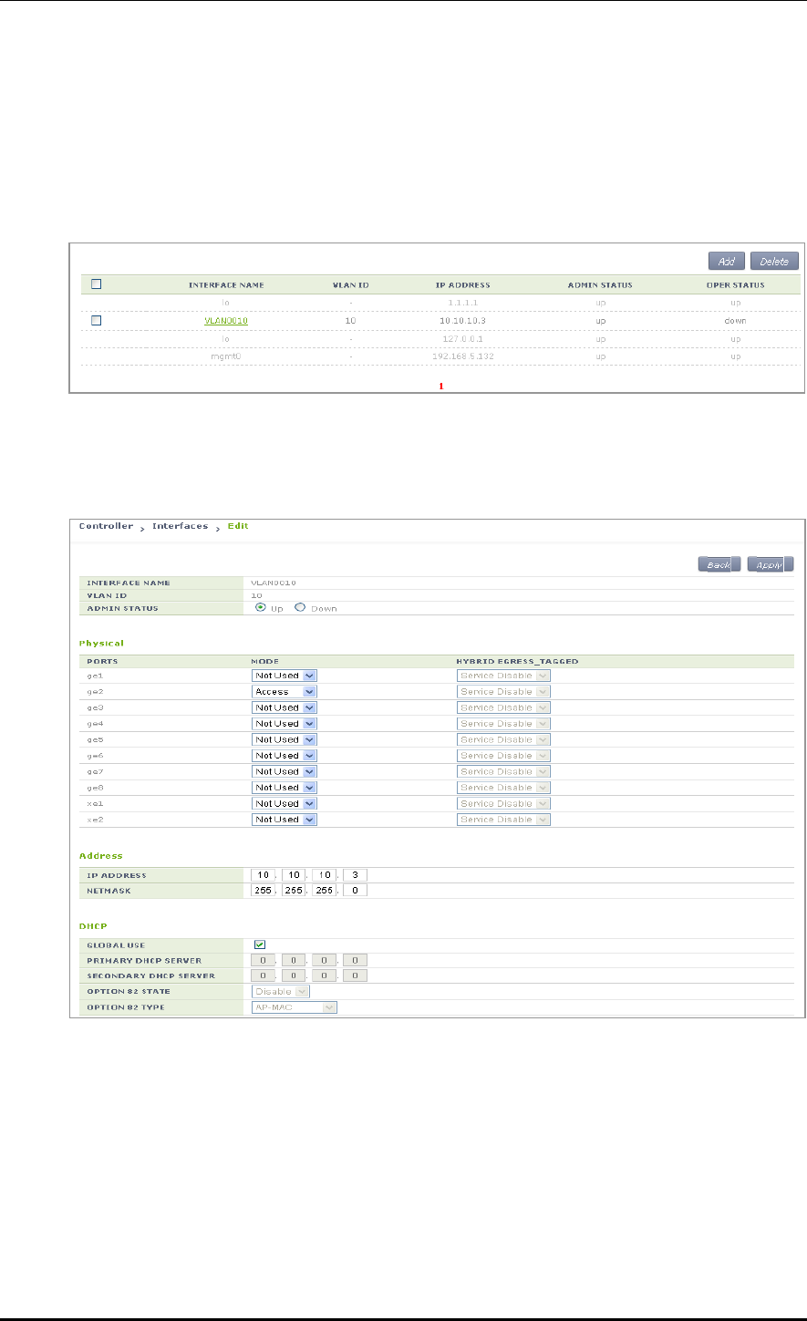
CHAPTER 5. WLAN Management
© SAMSUNG Electronics Co., Ltd. page 247 of 628
Configuration using Web UI
[Configuration at Interface]
In the menu bar of <WEC Main window>, select <Configuration> and then select the
<Controller> <Interfaces> menu in the sub-menus. In the interface, you can see the
page where you can change the Option 82.
Figure 121. Primary/Secondary server configuration (1)
Select an item in the list and perform detail configuration.
Figure 122. Primary/Secondary server configuration (2)
After unchecking the GLOBAL USE checkbox in the DHCP part, configure PRIMARY
DHCP SERVER and ‘SECONDARY DHCP SERVER’ and then click the <Apply> button.

CHAPTER 5. WLAN Management
© SAMSUNG Electronics Co., Ltd. page 248 of 628
[Configuration at Global]
In the menu bar of <WEC Main window>, select <Configuration> and then select the
<DHCP> <Proxy> menu in the sub-menus.
Configure the PRIMARY SERVER and SECONDARY SERVER of the Global Parameter.
If you does Global configuration, the configuration is applied to all the interfaces whose
‘GLOBAL USE’ checkbox is checked in the DHCP configuration of APC interface.
Figure 123. Primary/Secondary server configuration (3)

CHAPTER 5. WLAN Management
© SAMSUNG Electronics Co., Ltd. page 249 of 628
5.5 Radio Service Configuration
The APC supports WLAN-based radio configuration. You can enable or disable WMM
based on WLAN and change DTIM and station idle timeout.
Configuration using CLI
1) Go to configure wlan-radio-service mode of CLI.
APC# configure terminal
APC/configure# wlan-radio-service
APC/configure/wlan-radio-service#
2) Configure whether to enable or disable WMM.
wmm-mode [WLAN_ID] [MODE]
Parameter
Description
WLAN_ID
WLAN ID (range: 1-240)
MODE
WMM configuration mode (disable/enable)
3) Configure DTIM.
dtim [WLAN_ID] [DTIM]
Parameter
Description
WLAN_ID
WLAN ID (range: 1-240)
DTIM
Beacon DTIM: 1~255(default: 1)
4) Configure station idle timeout.
sta-idle-timeout [WLAN_ID] [TIMEOUT]
Parameter
Description
WLAN_ID
WLAN ID (range: 1-240)
TIMEOUT
Station idle timeout (range: 30-3600, unit: 15 s, default: 300)
5) To check the configured information, use the ‘show wlan-radio-service’ command.
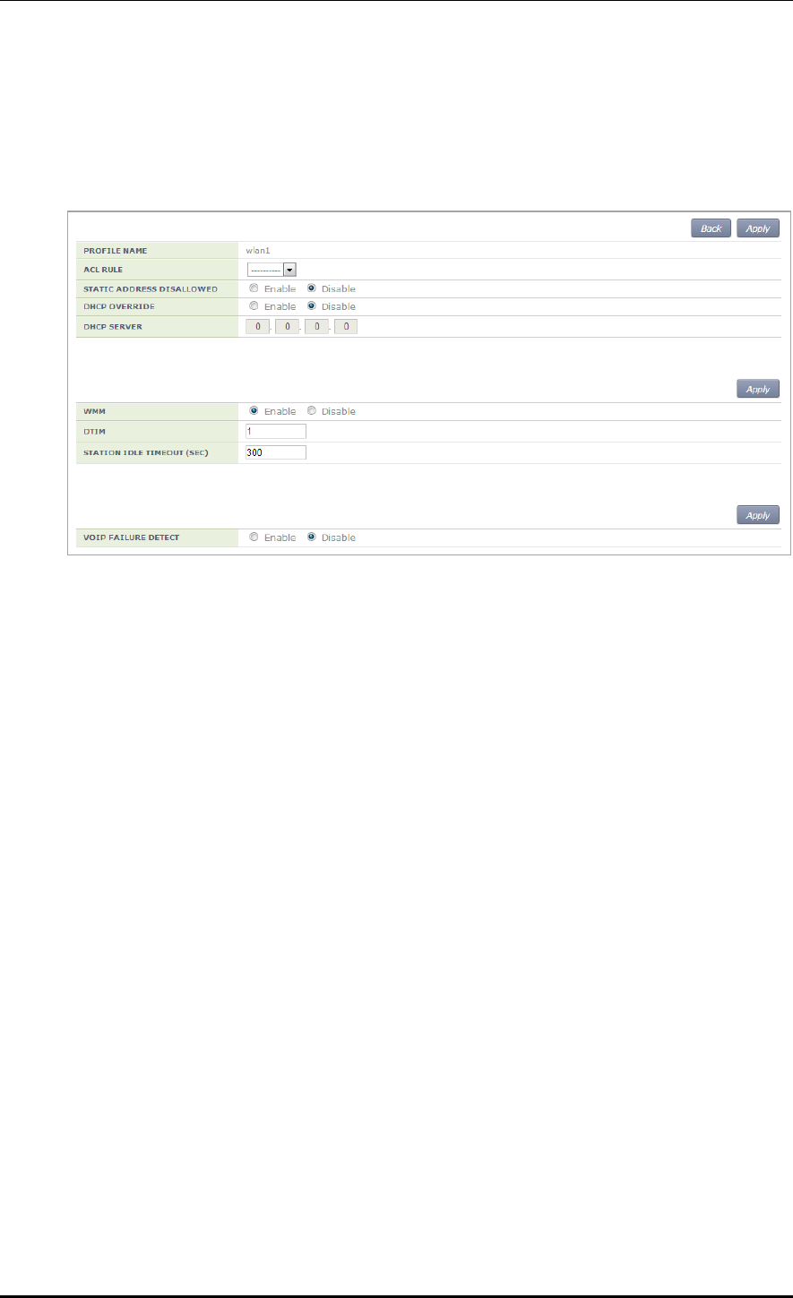
CHAPTER 5. WLAN Management
© SAMSUNG Electronics Co., Ltd. page 250 of 628
Configuration using Web UI
In the menu bar of <WEC Main window>, select <Configuration> and then select the
<WLANs> menu in the sub-menus. Select a WLAN ID to change in the WLANs screen
and go to the <Advanced> tab.
Figure 124. Radio service configuration
After configuring the below items, click the <Apply> button.
WMM: Configures the WMM mode.
DTIM: Enter a DTIM value (1-255).
STATION IDLE TIMEOUT: Enter a station idle timeout value. The value range is 30-
3600 and it must be the multiple of 15.

CHAPTER 6. Wi-Fi Configuration
© SAMSUNG Electronics Co., Ltd. page 251 of 628
CHAPTER 6. Wi-Fi Configuration
This chapter describes how to manage the 802.11a, 80211.bg, 802.11n or 80211ac device of
W-EP AP.
An 802.11n device supports 2.4 GHz and 5 GHz wireless bandwidth and high data
processing speed.
6.1 802.11a/b/g/n/ac Radio Property
6.1.1 802.11a/b/g Configuration
The configuration of radio property for 802.11a/b/g/ac is as follows:
Configuration using CLI
1) Go to configure radio mode to configure of CLI. The radio mode can be either
‘80211a’ or ‘80211bg’.
An example of entering into 80211a is shown below.
APC# configure terminal
APC/configure# 80211a
APC/configure/80211a#
2) Configure the channel of an AP.
channel [CHANNEL] ap [AP_ID]: Configures the channel of an AP.
channel [CHANNEL] ap [AP_ID] fixed: A channel is designed to be fixed and it is
not affected by the automatic adjustment function such as RRM. (When executing
the ‘show 80211a summary’ or ‘show 80211bg summary’, the channel value is
displayed in ‘*’.)
Parameter
Description
CHANNEL
Channel Configuration
- Range for 80211a: 36-165
- Range for 80211bg: 1-14
AP_ID
AP ID (range: 1-3000)

CHAPTER 6. Wi-Fi Configuration
© SAMSUNG Electronics Co., Ltd. page 252 of 628
3) Configure channel of multiple APs belonging to the group.
channel [CHANNEL] group [GROUP_ID] all-ap/active-ap: Channel is configured
for multiple APs.
channel [CHANNEL] group [GROUP_ID] all-ap/active-ap fixed: Channel is fixed
and is not affected by automatic adjustment functions such as RRM. (Channel
values are indicated as * when retrieved by ‘show 80211a summary’ or ‘show
80211bg summary’.)
Parameter
Description
CHANNEL
Channel Configuration
- Range for 80211a: 36-165
- Range for 80211bg: 1-14
GROUP_ID
ID of the AP group
all-ap
Applies to all APs in the group
active-ap
Applies to all live APs in the group
4) Configure the TX power of an AP.
txPower [POWER] ap [AP_ID]: Configures a TX power.
txPower [POWER] ap [AP_ID]fixed: The TX power is configured as fixed and it is
not affected by the automatic adjustment function such as RRM. (When executing
the ‘show 80211a summary’ or ‘show 80211bg summary’, the channel value is
displayed in ‘*’.)
Parameter
Description
POWER
TX power value (range: 3-23)
AP_ID
AP ID (range: 1-3000)
5) Configure TX power of multiple APs belonging to the group.
txPower [POWER] group [GROUP_ID] all-ap/active-ap: TX Power Setting
txPower [POWER] group [GROUP_ID] all-ap/active-ap fixed: TX power is fixed
and is not affected by automatic adjustment functions such as RRM. (Channel
values are indicated as * when retrieved by ‘show 80211a summary’ or ‘show
80211bg summary’.)
Parameter
Description
POWER
TX power value (range: 3-23)
GROUP_ID
ID of the AP group
all-ap
Applies to all APs in the group
active-ap
Applies to all live APs in the group

CHAPTER 6. Wi-Fi Configuration
© SAMSUNG Electronics Co., Ltd. page 253 of 628
6) To check the configured channel and TX power information, use the following
command.
WEC8500# show 80211a[|80211bg] summary
AP Name MAC Address Operation State Channel TxPower
----------------- ----------------- --------------- -------- --------
AP_f4d9fb23bfb9 F4:D9:FB:23:BF:B9 1 161 10 *
AP_f4d9fb23c2b9 F4:D9:FB:23:C2:B9 1 157 5
AP_f4d9fb23c079 F4:D9:FB:23:C0:79 1 153 5
AP_f4d9fb23baf9 F4:D9:FB:23:BA:F9 1 149 5
AP_f4d9fb23beb9 F4:D9:FB:23:BE:B9 1 64 5
In this example, the AP_f4d9fb23bfb9 whose Tx Power is displayed as 10* has a fixed
TX power.
7) Configure the beacon period of an AP.
beacon period [PERIOD] global
Parameter
Description
PERIOD
Beacon period (range: 40-3500)
8) Configure the fragmentation threshold of an AP.
threshold fragmentation [THRESHOLD] global
Parameter
Description
THRESHOLD
Fragmentation threshold (range: 256-8000)
9) Configure the data rate of an AP.
rate [MODE] [RATE] global
Parameter
Description
MODE
Mode (basic/supported)
- basic: Basic rate at which a terminal connects to an AP.
- supported: A connected terminal that supports the supported rate
can communicate with an AP at the supported rate.
RATE
Data rate
- Range for 80211a: 6, 9, 12, 18, 24, 36, 48, or 54 Mbps
- Range for 80211bg: 1, 2, 5.5, 6, 9, 11, 12, 18, 24, 36, 48, or 54 Mbps
10) To check the configured beacon period, fragmentation threshold, and data rate
information, uses the ‘show 80211a radio-config global’ command.
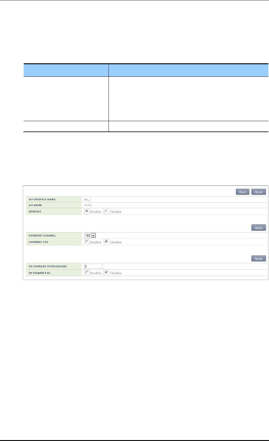
CHAPTER 6. Wi-Fi Configuration
© SAMSUNG Electronics Co., Ltd. page 254 of 628
11) Configure the bandwidth of the AP. Bandwidth can be configured only for 80211a/n/ac.
bandwidth [BANDWIDTH] ap [AP_ID]: Bandwidth is configured for a specific AP.
bandwidth [BANDWIDTH] global: Bandwidth is configured for all APs.
Parameter
Description
BANDWIDTH
- 20: 20 MHz
- 40: 40 MHz
- 80: 80 MHz
- 160: 160 MHz (to be supported in the future)
- 8080: 80 + 80 MHz (to be supported in the future)
AP_ID
ID of the AP (range: 1-3000)
Configuration using Web UI
In the menu bar of <WEC Main window>, select <Configuration> and then select the
<Access Points> <802.11a/n> or <802.11b/g/n> menu in the sub-menus.
An example of selecting 802.11a/n is shown below.
Figure 125. 802.11a/b/g/n radio (1)
The configuration items are as follows:
[AP Service Configuration]
SERVICE: Enable or disable the radio service.
[Channel Configuration]
CURRENT CHANNEL: Configures a channel.
Range for 80211a: 36-165
Range for 80211bg: 1-14
CHANNEL FIX: The configured channel is configured as fixed and it is not affected
by the automatic adjustment function such as RRM. When selecting the <Monitor>
<Access Points> <Radio> <802.11a/n/ac> or <802.11b/g/n> menu, the
channel value is displayed as *. (Optional)
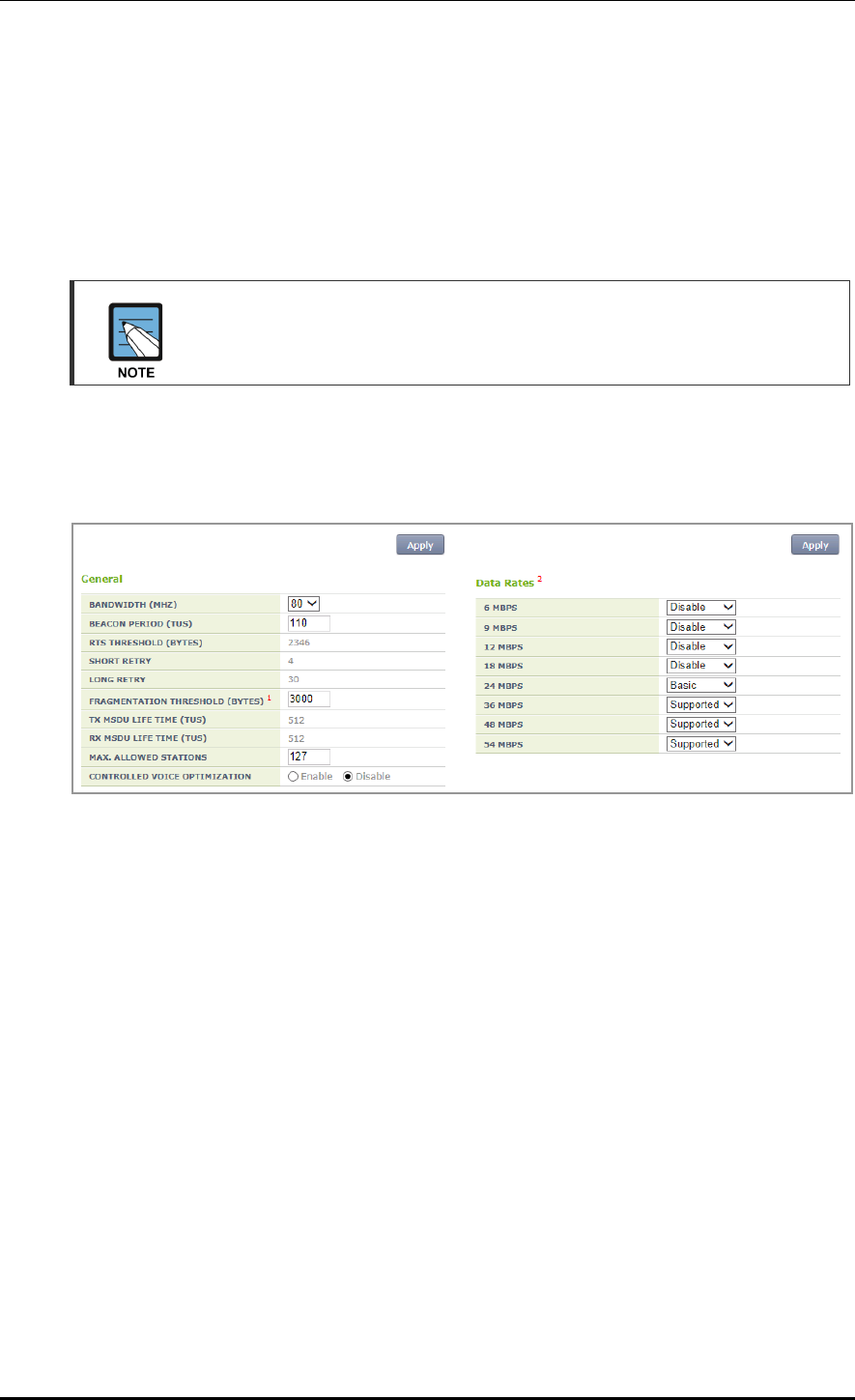
CHAPTER 6. Wi-Fi Configuration
© SAMSUNG Electronics Co., Ltd. page 255 of 628
[TX power Configuration]
TX CURRENT POWER: TX Power (range: 3-23)
TX POWER FIX: The configured TX power is configured as fixed and it is not
affected by the automatic adjustment function such as RRM. When selecting the
<Monitor> <Access Points> <Radio> <802.11a/n/ac> or <802.11b/g/n>
menu, the Tx power value is displayed as *. (Optional)
To check the configured channel and TX power information, go to <Monitor>
<Access Points> <Radio> <802.11a/n/ac> or <802.11b/g/n>.
In the menu bar of <WEC Main window>, select <Configuration> and then select the
<Radio> <802.11a/n/ac> or <802.11b/g/n> <802.11h> menu in the sub-menus.
An example of selecting 802.11a/n/ac is shown below.
Figure 126. 802.11a/b/g/n radio (2)
[General]
BANDWIDTH: Configures bandwith (range: 20, 40, 80). Available for 802.11a/n/ac only.
BEACON PERIOD: Beacon period (range: 40-3500)
FRAGMENTATION THRESHOLD: AP fragmentation threshold (range: 256-8000)
MAX. CLIENT COUNTS: Limits the number of connected clients per radio
CONTROLLED VOICE OPTIMIZATION: Configures voice optimization.
[Data Rates]
The data rate selection options are as follows:
Basic: Basic rate supported for a terminal to connect to an AP.
Supported: A connected terminal that supports the supported rate can communicate
with an AP at the supported rate.
Data Rates: data rate
Range for 80211a: 6, 9, 12, 18, 24, 36, 48, or 54 Mbps
Range for 80211bg: 1, 2, 5.5, 6, 9, 11, 12, 18, 24, 36, 48, or 54 Mbps

CHAPTER 6. Wi-Fi Configuration
© SAMSUNG Electronics Co., Ltd. page 256 of 628
6.1.2 802.11n Configuration
The 802.11n configuration is as follows:
Configuration using CLI
1) Go to configure radio mode (80211a or 80211bg) to configure of CLI.
WEC8500# configure terminal
WEC8500/configure# 80211a
2) Go to the 11n-support mode.
WEC8500/configure/80211a#11n-support
3) Configure an AP so that it can support 802.11n property.
WEC8500/configure/80211a/11n-support# enable [AP_ID]
Parameter
Description
AP_ID
AP ID (range: 1-500)
4) Configure the Modulation and Coding Scheme (MCS) rate.
WEC8500/configure/80211a/11n-support# mcs [RATE] ap [AP_ID]
Parameter
Description
RATE
MSC rate (range: 0-23)
AP_ID
AP ID (range: 1-500)
5) To check the configured 11n-support information, use the ‘show 80211a radio-config
ap [AP_ID]’ command.
Configuration using Web UI
In the menu bar of <WEC Main window>, select <Configuration> and then select the
<Access Points> <802.11a/n/ac> or <802.11b/g/n> <General> menu in the sub-
menus.
Perform the configuration by referring to ‘6.1.1 802.11a/b/g Configuration’.

CHAPTER 6. Wi-Fi Configuration
© SAMSUNG Electronics Co., Ltd. page 257 of 628
6.1.3 802.11ac Configuration
The 802.11ac configuration is as follows:
Configuration using CLI
1) Go to configure radio mode of 80211a to configure.
WEC8500# configure terminal
WEC8500/configure# 80211a
2) Enter 11ac-support mode.
WEC8500/configure/80211a#11ac-support
3) Configure the AP so that it can support the 802.11ac property.
WEC8500/configure/80211a/11ac-support# enable [AP_ID]
Parameter
Description
AP_ID
ID of the AP (range: 1-500)
4) Configure the Modulation and Coding Scheme (MCS) rate.
WEC8500/configure/80211a/11n-support# mcs [RATE] ap [AP_ID]
Parameter
Description
RATE
MSC rate (range: 0-23)
AP_ID
ID of the AP (range: 1-500)
5) To check the configured 11ac-support information, use the ‘show 80211a radio-config
ap[AP_ID]’ command.
Configuration using Web UI
In the menu bar of <WEC Main Window>, select <Configuration> and then select
<Access Points> <802.11a/n/ac> or <Radio> <802.11a/n/ac> <802.11n/ac> in
the submenu.
An example of selecting 802.11a/n/ac is shown below.
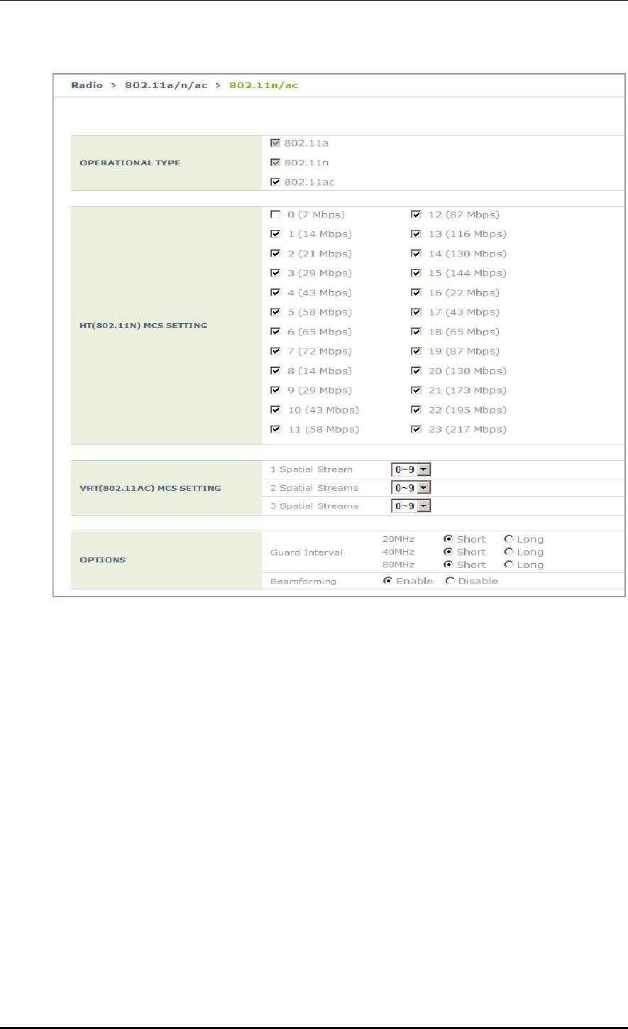
CHAPTER 6. Wi-Fi Configuration
© SAMSUNG Electronics Co., Ltd. page 258 of 628
[OPERATIONAL TYPE]
Enable/disable 11ac operation.
[VHT (802.11AC) MCS SETTING]
Determine the spatial stream count for each AP model and enter maximum MCS value
for each spatial stream count.
Example: maximum of seven MCS for one spatial stream, maximum of eight MCS for
two spatial streams, and maximum of nine MCS for three spatial streams
1 spatial stream: 7
2 spatial streams: 8
3 spatial streams: 9
[OPTIONS]
Guard-interval (11n): Select short/long for Guard-interval 20/40 Mhz respectively.
Guard-interval (11ac): Select short/long for Guard-interval 20/40/80 Mhz respectively.

CHAPTER 6. Wi-Fi Configuration
© SAMSUNG Electronics Co., Ltd. page 259 of 628
6.2 Wi-Fi QoS Configuration
The APC provides various QoS in the wire/wireless section for every packet type (voice,
video, best-effort, or background). The QoS can be configured for each wireless section
(2.4 GHz, 5 GHz).
6.2.1 QoS Configuration of Wireless Terminal
The system provides probable QoS by changing the Enhanced Distributed Channel Access
(EDCA) parameter in a wireless section.
Configuration using CLI
To configure an EDCA profile in the upward wireless section of a wireless terminal,
execute the command as follows:
1) Go to configure radio mode to configure of CLI.
APC# configure terminal
APC/configure# [80211a/80211bg]
2) Apply the EDCA profile.
edca-parameters [PROFILE] station
Parameter
Description
PROFILE
Configures each EDCA profile (wmm_default_sta/wmm_default_ap/
edca_user1/edca_user2).
3) To check the application status of a configured EDCA profile, use the ‘show 80211a
[80211bg] qos edca-parameters wmm_default_sta’ command.
Configuration using Web UI
In the menu bar of <WEC Main window>, select <Configuration> and then select the
<Radio> <802.11a/n> or <802.11b/g/n> <QoS> menu in the sub-menus.
In the Qos menu, there are Wired and Wireless tab. To change the Station EDCA parameter,
select the Wired tab. If you want to change the AP EDCA parameter to configure the QoS
of an AP wireless section, select the Wireless tab.
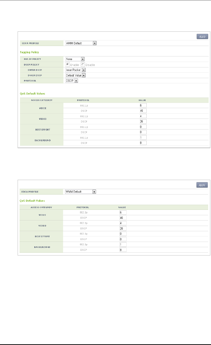
CHAPTER 6. Wi-Fi Configuration
© SAMSUNG Electronics Co., Ltd. page 260 of 628
[Wired tab]
Figure 127. QoS configuration of a wireless terminal (1)
[Wireless tab]
Figure 128. QoS configuration of a wireless terminal (2)

CHAPTER 6. Wi-Fi Configuration
© SAMSUNG Electronics Co., Ltd. page 261 of 628
6.2.2 QoS Configuration of AP
6.2.2.1 Wire Section
The APC provides QoS in a wire section using 802.1p and Differentiated Services Code
Point (DSCP) marking and it can adjust packet traffics because it can adjust queue length
depending on packet type.
Configuration using CLI
To configure the Station QoS parameter that will be applied to the wire section between
APC and AP, execute the command as follows:
1) Go to configure QoS mode of a wireless section of CLI.
APC# configure terminal
APC/configure# [80211a/80211bg] qos
APC/configure/80211a/qos#
2) Configure a QoS policy to a wire section packet.
802.1P Policy: enable policy [802_1P]
DSCP Policy: enable policy [DSCP_OUTER] [DSCP_INNER]
Parameter
Description
enable
Enables 802.1p or DSCP marking.
802_1P
802.1p configuration (user_priority/default)
- user_priority: Marks the 802.1p or User Priority value of an incoming
packet into the 802.1p field.
- default: Marks pre-configured basic value to the 802.1p field.
DSCP_OUTER
DSCP Outer configuration (inner_packet/default)
- inner_packet: Marks the DSCP value of an incoming packet into the
Outer DSCP field.
- default: Marks pre-configured basic value to the Outer DSCP field.
DSCP_INNER
DSCP Inner configuration (no_mark/default)
- no_mark: Marks no value into the Inner DSCP field.
- default: Marks pre-configured basic value to the Inner DSCP field.
3) Configure a default 802.1p value per packet.
dot1p-tag [PACKET_TYPE] [802.1P_TAG]
Parameter
Description
PACKET_TYPE
Packet type configuration (voice/video/best_effort/background)
802.1P_TAG
Default 802.1p value

CHAPTER 6. Wi-Fi Configuration
© SAMSUNG Electronics Co., Ltd. page 262 of 628
4) Configure a default DSCP value per packet.
dscp-tag [PACKET_TYPE] [DSCP TAG]
Parameter
Description
PACKET_TYPE
Packet type configuration (voice/video/best_effort/background)
DSCP_TAG
Default DSCP value
5) Configure a protocol to distinguish packet types.
protocol [PROTOCOL]
Parameter
Description
PROTOCOL
Protocol configuration (none/dot1p/dscp)
- none: Determine the type of every incoming packet with best effort.
- dot1p: Judge the packet type by checking the 802.1p field of an
incoming packet.
- dscp: Judge the packet type by checking the DSCP field of an
incoming packet.
The packet judgment criteria are as follows: For example, if the packet type is voice,
the 802.1p input value is 6 or 7 and the input range of DSCP value is 46-63.
Also, if the packet type is video, the 802.1p input value is 4 or 5 and the input range of
DSCP value is 24-45.
802.1p
DSCP
Packet type
6, 7
46~63
voice
4, 5
24~45
video
0, 3
0~7, 16~23
best effort
1, 2
8~15
background
6) To check the configured policy and QoS parameter information per packet, use the
‘show 80211a[|80211bg] qos policy’ command.

CHAPTER 6. Wi-Fi Configuration
© SAMSUNG Electronics Co., Ltd. page 263 of 628
Configuration using Web UI
In the menu bar of <WEC Main window>, select <Configuration> and then select the
<Radio> <802.11a/n> or <802.11b/g/n> <QoS> menu in the sub-menus.
1) Select one out of None/Default/User Priority in the 802.1P POLICY drop-down list of
Tagging Policy.
2) To disable a DSCP policy in the DSCP POLICY, select Disable.
3) To enable a DSCP policy in the DSCP POLICY, select Enable.
a) Select one out of Inner Packet/Default Value in the OUTER DSCP drop-down list.
b) Select one out of No Mark/Default Value in the INNER DSCP drop-down list.
4) Select one out of None/802.1p/DSCP in the PROTOCOL drop-down list.
5) Enter 802.1p or a DSCP value into the QoS Default Values.
6) Click the <Apply> button to apply.
6.2.2.2 Wireless Section
The system can provide QoS service in a wireless section for each AP downward packet
type (voice, video, best effort, background). You can configure 802.1p and DSCP tag which
are the criteria used to select access category.
Configuration using CLI
1) Go to configure QoS mode of a wireless section of CLI.
APC# configure terminal
APC/configure# [80211a/80211bg] qos
APC/configure/80211a/qos#
2) Configure 802.1p or DSCP tag value to use for a packet type.
ap-tags [PACKET_TYPE] [802.1P TAG] [DSCP TAG]
Parameter
Description
PACKET_TYPE
Packet type configuration (voice/video/best_effort/background)
802.1P_TAG
802.1p configuration
DSCP_TAG
DSCP tag configuration
3) To check the QoS parameter information of a configured AP, use the ‘show 80211a
[80211bg] qos ac-profile [PACKET_TYPE]’ command.

CHAPTER 6. Wi-Fi Configuration
© SAMSUNG Electronics Co., Ltd. page 264 of 628
Configuration using Web UI
In the menu bar of <WEC Main window>, select <Configuration> and then select the
<Radio> <802.11a/n> or <802.11b/g/n> <QoS> menu in the sub-menus.
Figure 129. QoS configuration of AP (wireless section)
In the Access Point tab, enter 802.1p or a DSCP value into the QoS Default Values.
Click the <Apply> button to apply.

CHAPTER 6. Wi-Fi Configuration
© SAMSUNG Electronics Co., Ltd. page 265 of 628
6.2.3 Configuring QoS Profile of a Specific Terminal
You can configure a QoS profile that is applied to a specific wireless terminal.
This QoS profile is applied from the RADIUS server of a wireless terminal during
authentication.
Configuration using CLI
1) Go to configure QoS profile configuration mode of CLI.
APC# configure terminal
APC/configure# qos <profile name>
APC/configure/qos Samsung #
2) Configure 802.1p and a DSCP value that will be used for each access category.
ac [AC] [802.1P_TAG] [DSCP_TAG]
Parameter
Description
AC
Access Category(AC_VO/AC_VI/AC_BE/AC_BK)
802.1P_TAG
802.1p configuration (range: 0-7)
DSCP_TAG
DSCP tag configuration (range: 0-63)
3) Configure the brief information of a profile.
description [DESCRIPTION]
Parameter
Description
DESCRIPTION
Profile description
4) Configure maximum allowed 802.1p priority value used in the Traffic Identifier (TID)
field of AP QoS packet.
max-dot1p <802.1p tag>
Parameter
Description
802.1P_TAG
Maximum allowed 802.1p configuration (range: 0-7)
5) To check the configured QoS profile information, use the ‘show qos profile’ command.
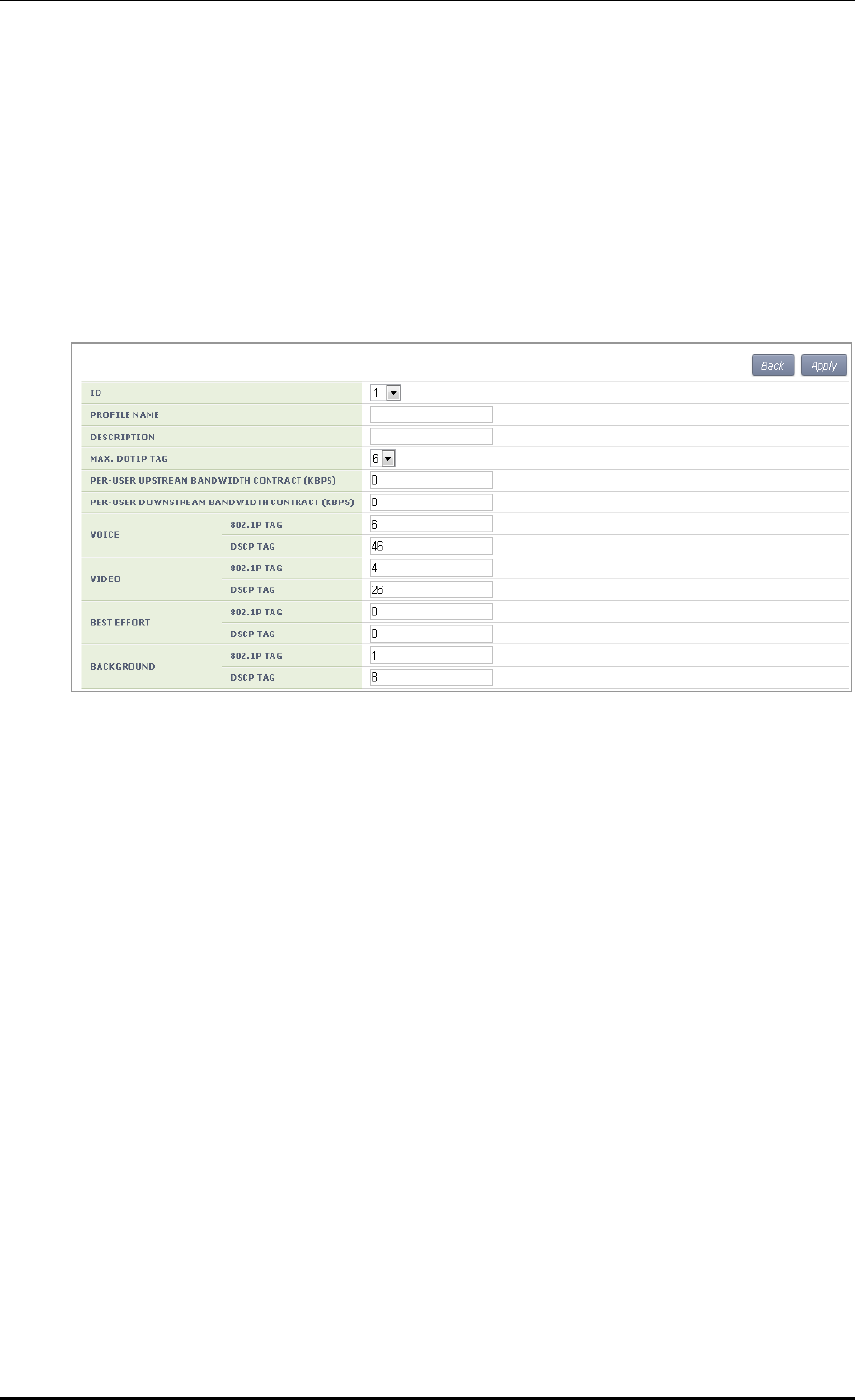
CHAPTER 6. Wi-Fi Configuration
© SAMSUNG Electronics Co., Ltd. page 266 of 628
Configuration using Web UI
In the menu bar of <WEC Main window>, select <Configuration> and then select the
<User QoS> menu in the sub-menus. To create a QoS profile to apply to a terminal, click
the <Add> button in the initial window.
The QoS addition window consists of the following QoS parameters. By entering each QoS
parameter, you can configure the QoS profile of a specific terminal or configure the usage
control function for each user.
Figure 130. Configuring QoS profile of a specific terminal
ID: ID (range: 1-16)
PROFILE NAME: Profile name
DESCRIPTION: Profile description
MAX. DOT1P TAG: Maximum allowed 802.1p tag (range: 0-7)
PER-USER UPSTREAM BANDWIDTH CONTRACT: Maximum upward usage
(range: 0-450000)
PER-USER DOWNSTREAM BANDWIDTH CONTRACT: Maximum downward
usage (range: 0-450000)
VOICE/VIDEO/BEST EFFORT/BACKGROUND: Enter 802.1P TAG (range: 0-7)
and DSCP TAG (range: 0-64) for each item.
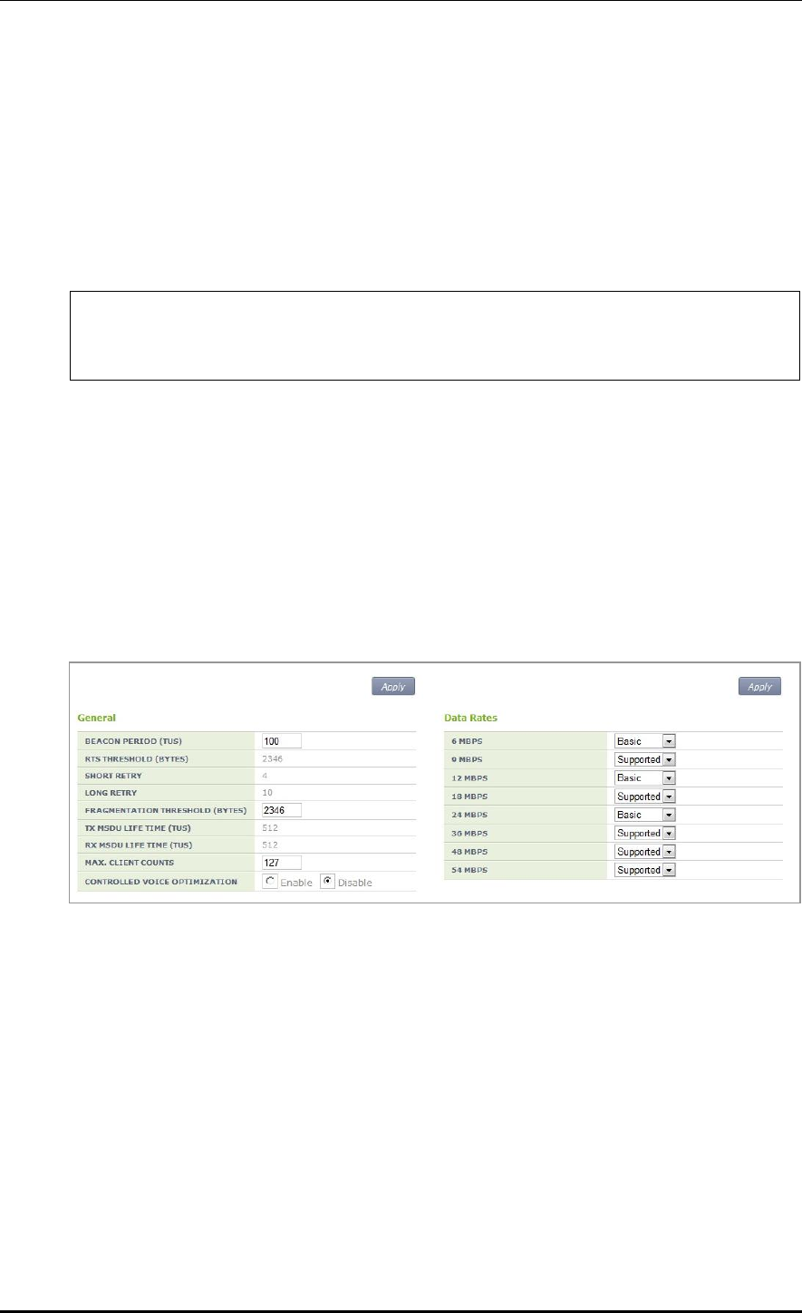
CHAPTER 6. Wi-Fi Configuration
© SAMSUNG Electronics Co., Ltd. page 267 of 628
6.2.4 Voice Optimization Configuration
The APC configures an EDCA parameter value that is optimized for voice service to an AP
in real-time.
Configuration using CLI
1) Go to configure radio cvo mode to configure of CLI.
APC# configure terminal
APC/configure# [80211a|80211bg] cvo
APC/configure/80211a/cvo#
2) Enable or disable the function.
[no] enable
3) To check the configured information, use the ‘show 80211a cvo config’ command.
Configuration using Web UI
In the menu bar of <WEC Main window>, select <Configuration> and then select the
<Radio> <802.11a/n> or <802.11b/g/n> <General> menu in the sub-menus.
Figure 131. Configuring voice optimization
To enable Controlled Voice Optimization (CVO), select Enable in the CONTROLLED
VOICE OPTIMIZATION. To disable it, select Disable.

CHAPTER 6. Wi-Fi Configuration
© SAMSUNG Electronics Co., Ltd. page 268 of 628
6.3 802.11h Configuration
The APC supports the configuration and transmission power limitation for the Dynamic
Frequency Selection (DFS) function in an AP. When the AP detects radar, an event is sent
to the WEM and a detouring channel can be configured in the AP.
Configuration using CLI
For channel switching announcement related configuration and power constraint value
configuration in an AP, execute the command as follows:
1) Go to configure 80211h configuration mode of CLI.
APC# configure terminal
APC/configure# 80211h
APC/configure/80211h#
2) Configure the 802.11h information.
channel-switch [MODE] [RESTRICTION] [SWITCH COUNT]
Parameter
Description
MODE
Whether the switching announcement function is enabled/disabled
RESTRICTION
Whether the channel packet transmission restriction mode is
enabled (disable/enable)
SWITCH COUNT
Waiting time until channel switching announcement
3) Configure the transmission power of a wireless terminal.
power-constraint [VALUE]
Parameter
Description
VALUE
Transmission power(0-31 dB)
4) To check the configuration information, use the ‘show 80211h configuration’ command.

CHAPTER 6. Wi-Fi Configuration
© SAMSUNG Electronics Co., Ltd. page 269 of 628
Configuration using Web UI
In the menu bar of <WEC Main window>, select <Configuration> and then select the
<Radio> <802.11a/n> <802.11h> menu in the sub-menus.
Figure 132. Configuring 802.11h
POWER CONSTRAINT: Power constraint value (0-100)
CHANNEL SWITCH: Enables channel switch announcement.
RESTRICTION MODE: Configures transmission restriction.
CHANNEL SWTICH COUNT: Enter a waiting time until channel switching
announcement. Target Beacon Transmission Times (TBTT)

CHAPTER 6. Wi-Fi Configuration
© SAMSUNG Electronics Co., Ltd. page 270 of 628
6.4 Country Code
You can use a country code to restrict the number of channels that can be used in an AP and
the maximum transmission power of each channel.
Configuration using CLI
To configure the country code function, go to country mode first by executing the
following command.
APC# configure terminal
APC/configure# country
APC/configure/country#
[Global Country Code Configuration]
If you configure a global country code, the country code can be specified to all the
connected APs at the same time. The command is shown below.
set-global [COUNTRY_CODE] [VALUE]
Parameter
Description
COUNTRY_CODE
Country code to configure
VALUE
Environment configuration (both/outdoor/indoor/none)
To check the configuration information, use the ‘show country global-config’ command.
[AP Country Code Configuration]
To configure a country code, execute the command as follows:
set-ap [AP_ID] [COUNTRY_CODE] [VALUE]
Parameter
Description
AP_ID
AP ID (range: 1-500)
COUNTRY_CODE
Country code to configure
VALUE
Environment configuration (both/outdoor/indoor/none)
To check the configuration information, use the ‘show country ap-config [AP_ID]’
command.

CHAPTER 6. Wi-Fi Configuration
© SAMSUNG Electronics Co., Ltd. page 271 of 628
[Editing Country Code]
You can add or delete an operation channel per country and change maximum transmission
power per channel.
The command used to add or delete a channel per country is shown below.
add-channel [COUNTRY_CODE] [CHANNEL_NUMBER] [MAX_TX_POWER]:
Adds a channel.
del-channel [COUNTRY_CODE] [CHANNEL_NUMBER]: Deletes a channel.
Parameter
Description
COUNTRY_CODE
Country code to configure
CHANNEL_NUMBER
Channel to configure.
MAX _TX_POWER
Maximum transmission power per channel.
The command used to change maximum transmission power value of a channel for a
specific country code is shown below.
max-tx-power [COUNTRY_CODE] [CHANNEL_NUMBER] [MAX_TX_POWER]
Parameter
Description
COUNTRY_CODE
Country code to configure
CHANNEL_NUMBER
Channel to configure.
MAX _TX_POWER
Maximum transmission power per channel.
To check the configuration information, use the ‘show country information [COUNTRY_
CODE]’ command.
Parameter
Description
COUNTRY_CODE
Country code to configure
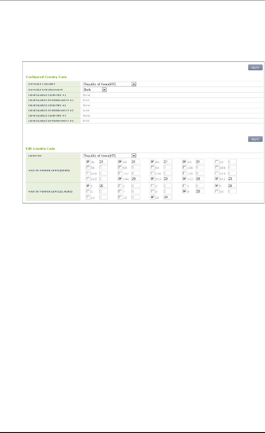
CHAPTER 6. Wi-Fi Configuration
© SAMSUNG Electronics Co., Ltd. page 272 of 628
Configuration using Web UI
In the menu bar of <WEC Main window>, select <Configuration> and then select the
<Controller> <Country> menu in the sub-menus.
Figure 133. Country code window (1)
[Global Country Code Configuration]
1) Select a country in the DEFAULT COUNTRY drop-down list of Configured Country
Code item. (Only an authenticated country code is supported.)
2) Select an environment in the DEFAULT ENVIRONMENT drop-down list.
Both: The terminal operation environment includes all the environments.
Outdoor: The terminal operation environment is outdoor.
Indoor: The terminal operation environment is indoor.
Non-country: A terminal is operating under non-country entity.
3) Click the <Apply> button to apply.
[Editing Country Code]
In the Edit Country Code item, you can add or delete an operation channel per country or
change maximum transmission power per channel.
1) Select a country in the COUNTRY drop-down list of Edit Country Code item.
(Only an authenticated country code is supported.)
2) Select a channel to add in the MAX TX POWER LEVEL (5 GHZ/2.4 GHZ) and enter
maximum transmission power level (0-30).
3) In the MAX TX POWER LEVEL (5 GHZ/2.4 GHZ), unselect a channel to delete.
4) Click the <Apply> button to apply.
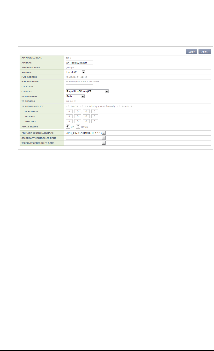
CHAPTER 6. Wi-Fi Configuration
© SAMSUNG Electronics Co., Ltd. page 273 of 628
[AP Country Code Configuration]
In the menu bar of <WEC Main window>, select <Configuration> and then select the
<Access Points> <General> menu in the sub-menus.
Figure 134. Country code window (2)
After selecting COUNTRY and ENVIRONMENT, click the <Apply> button.

CHAPTER 7. WLAN Additional Services
© SAMSUNG Electronics Co., Ltd. page 274 of 628
CHAPTER 7. WLAN Additional
Services
In this chapter, how to configure WLAN additional services such as wireless terminal
management, spectrum analysis, Call Admission Control (CAC) and Radio Resource
Management (RRM), etc. is described.
7.1 Managing Wireless Terminal
7.1.1 Information Retrieval Functions
Configuration using CLI
Using the following command, you can retrieve the information of a wireless terminal
being serviced by the APC.
show station summary: When you enter this command, the summary information of all
the wireless terminals connected to the APC is retrieved.
show station summary ap [AP_ID]: The information of wireless terminals of each AP
is retrieved.
show station summary bssid [BSSID_ID]: The information of wireless terminals of
each BSSID is retrieved.
show station summary wlan [WLAN_ID]: The information of wireless terminals of
each WLAN is retrieved.
show station detail [MAC_ADDRESS]: The detail information of a wireless terminal
that has a specific MAC address is retrieved.
show station stats ap-80211-stats [MAC_ADDRESS]: The WI-FI statistics
information of a wireless terminal is retrieved.
show station association history [MAC_ADDRESS]: The connection history of a
wireless terminal is retrieved.
show station stats debug all: The debug statistics information of a wireless terminal is
retrieved.
show station stats management_frame all: The debug statistics information of a
wireless terminal is retrieved.
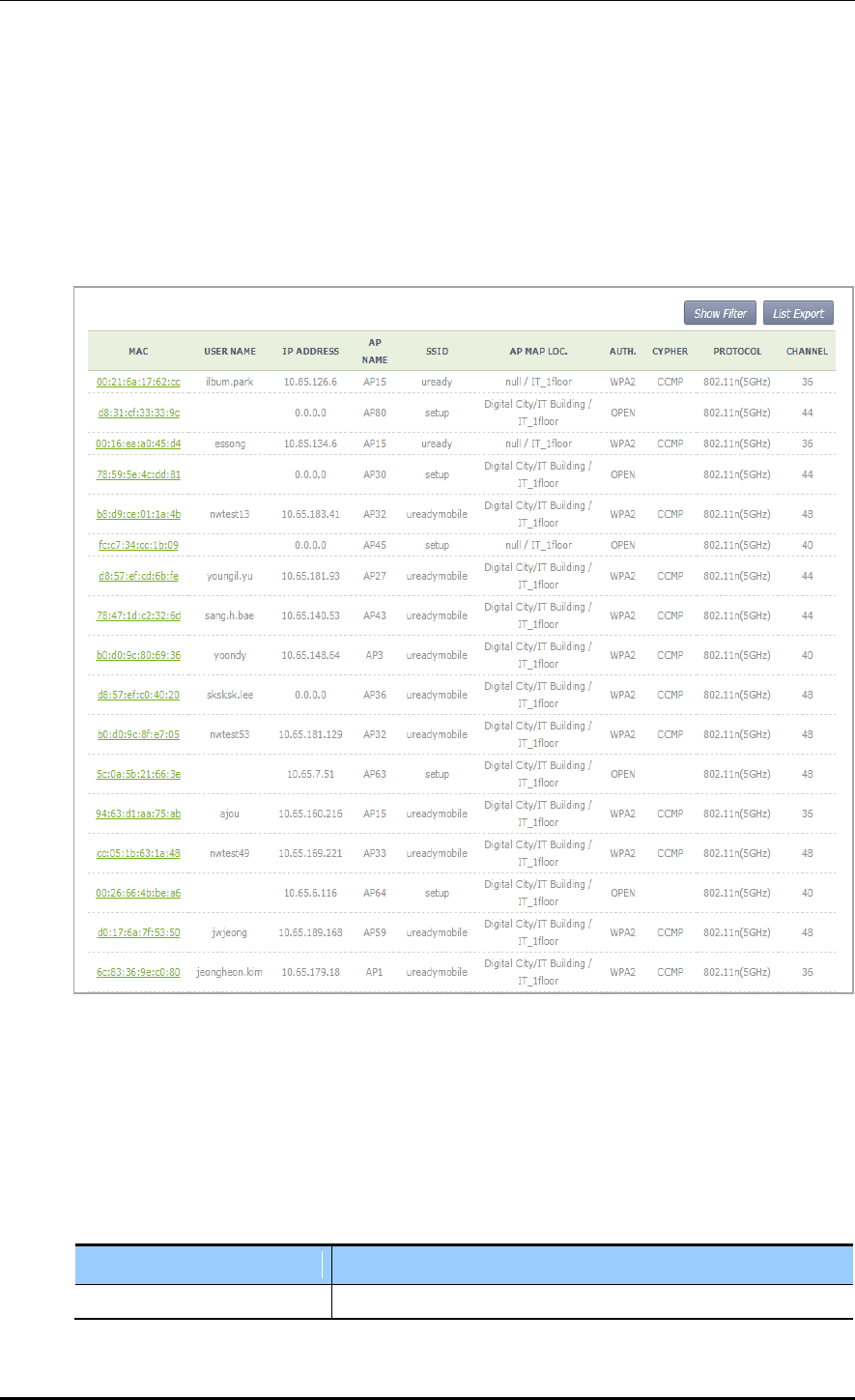
CHAPTER 7. WLAN Additional Services
© SAMSUNG Electronics Co., Ltd. page 275 of 628
Configuration using Web UI
In the menu bar of <WEC Main window>, select <Monitor> and then select the
<Stations> menu in the sub-menus. The brief information of each station is displayed in
the window.
To check the detail information of a specific station, click the MAC information of the
specific station in the Stations window list.
Figure 135. Information viewing window
7.1.2 Connection History related Configuration
You can configure maximum value for the connection history of a wireless terminal that
will be managed in the APC.
station number-of-assoc-tracking [COUNT]
Parameter
Description
COUNT
Maximum number of association tracking

CHAPTER 7. WLAN Additional Services
© SAMSUNG Electronics Co., Ltd. page 276 of 628
7.2 Handover Management
The handover releases a connection with an existing AP and connects to a new AP.
It provides seamless wireless LAN connection to a wireless terminal. The APC provides
both 802.11 standard handover and Samsung’s unique AirMove (Network Controlled
Handover) handover.
7.2.1 Connection History Information
Use the ‘show station association history [MAC_ADDRESS]’ command to check the
handover history information of a specific wireless terminal connected to the APC.
7.2.2 AirMove Configuration
Unlike the 802.11 standard handover where a wireless terminal performs the handover
function by itself, the AirMove handover is performed by the collaboration between
wireless terminals compatible with the APC. Therefore, the packet loss or handover time is
optimized. Some Samsung smartphones such as Galaxy S2 or S3, etc. provide the AirMove
function.
Configuration using CLI
To configure the AirMove related function, execute the following command to go to the
handover configuration mode.
WEC8500# configure terminal
WEC8500/configure# handover
[Handover Option Configuration]
handover [OPTION] [OPTION_DETAIL]
AirMove Configuration Item
Description
operation mode
Operation mode configuration
- OPTION: opmode
- OPTION_DETAIL: Each mode (VoIP/STA)
buffered-forwarding mode
Configures whether to use the buffered forwarding function.
- OPTION: fwd-buffering
- OPTION_DETAIL: Enable/Disable
decision delta
Configures the threshold of RSSI difference between a serving
AP and a target AP.
- OPTION: decision-delta
- OPTION_DETAIL: Threshold (dBm)
scan time on channel
Configures scanning time of a wireless terminal per channel.
- option: scan-time-channel
- OPTION_DETAIL: Time (ms)

CHAPTER 7. WLAN Additional Services
© SAMSUNG Electronics Co., Ltd. page 277 of 628
AirMove Configuration Item
Description
scan interleaving time
Configures the scanning interval of a wireless terminal.
- OPTION: scan-time-interleave
- OPTION_DETAIL: Time (ms)
Service time in scanning period
Configures a period when an wireless terminal
transmits/receives an actual data traffic after scanning.
- OPTION: scan-time-service
- OPTION_DETAIL: Time (ms)
scan report level
Configures the threshold of a scan report that will be
transmitted from an AP to the APC.
- OPTION: scan-report-level
- OPTION_DETAIL: scan report level (dBm)
Numbers of handover scan
attempts per channel
Configures the scanning times of a wireless terminal per
channel.
- OPTION: number-of-proreq
- OPTION_DETAIL: Number of times
Number of channels for which
scan is attempted
Configures the number of channels a wireless terminal will
scan at a time.
- OPTION: number-of-channel
- OPTION_DETAIL: Number of channels
scan trigger level
RSSI intensity at which a wireless terminal starts channel scanning
- OPTION -trigger-level
- OPTION_DETAIL: RSSI (dBm)
station decision delta
Configures the threshold of RSSI difference, measured in a
wireless terminal, between a serving AP and a target AP. If the
threshold is exceeded, a wireless terminal performs its
handover.
- OPTION: station-decision-delta
- OPTION_DETAIL: Threshold (dBm)
An example of using the command for each configuration item is as follows:
WEC8500/configure# handover opmode APP
WEC8500/configure# handover buffered-forwarding enable
WEC8500/configure# handover decision-delta 10
WEC8500/configure# handover scan-time-channel 10
WEC8500/configure# handover scan-time-interleave 1000
WEC8500/configure# handover scan-time-service 200
WEC8500/configure# handover scan-report-level -90
WEC8500/configure# handover number-of-proreq 3
WEC8500/configure# handover number-of-channel 4
WEC8500/configure# handover scan-trigger-level -65
WEC8500/configure# handover station-decision-delta 10
To check the configuration information, use the ‘show handover configuration’ command.
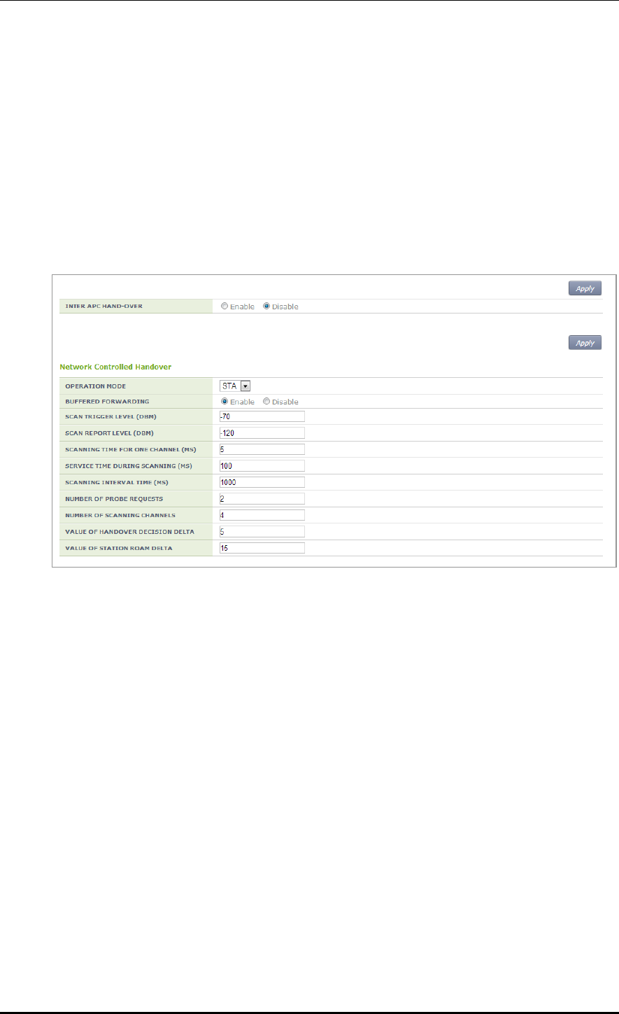
CHAPTER 7. WLAN Additional Services
© SAMSUNG Electronics Co., Ltd. page 278 of 628
[AirMove Enable/Disable Configuration]
The AirMove is enabled by default, so use the following command to disable it.
no handover mode NCHO
To check the configuration information, use the ‘show handover configuration’ command.
Configuration using Web UI
In the menu bar of <WEC Main window>, select <Configuration> and then select the
<Mobility Management> <Handover> menu in the sub-menus.
Figure 136. Handover window
You can enable or disable the intra handover function by selecting Enable/Disable in the
INTER APC HAND-OVER item. After configuring a value, click the <Apply> button to apply.
7.2.3 Inter APC Handover Configuration
The Inter APC handover is a technology that supports handover among several APC
systems. Depending on network configuration, the Inter APC L3 handover and Inter APC
L2 handover services are provided.
By using the clustering service, you can configure several APC systems into a single group.
Configures whether to use the Inter APC handover.
The default value of Inter APC handover is not configured.
handover inter-apc enable
To check the configuration information, use the ‘show handover configuration’ command.

CHAPTER 7. WLAN Additional Services
© SAMSUNG Electronics Co., Ltd. page 279 of 628
7.3 Call Admission Control (CAC) Configuration
The CAC function is provided to protect existing calls from the calls incoming to a
wireless LAN. The APC does not allow an additional call when maximum allowed number
of calls per radio is reached.
7.3.1 SIP ALG Configuration
To make Call Admission Control (CAC) working, the Session Initiation Protocol (SIP)
Application Layer Gateway (ALG) function must be enabled. The SIP ALG analyzes a SIP
packet and forwards VoIP communication status to the CAC.
Configuration using CLI
The SIP ALG related commands are as follows:
sipalg enable: Configures whether to enable the SIP ALG function.
sipalg sip-error-resp-enable(SIP ERROR RESPONSE): Configures how to reject a
received call when maximum allowed number of calls is exceeded.
Disable (default): No response for a received call connection request message.
The received message is not forwarded to the called side.
Enable: Rejects by transmitting 503 Service Unavailable SIP response for a
received call connection request message. The received message is not forwarded
to a called side.
sipalg sip-detect-long-call-enable (SIP DETECT LONG DURATION CALL):
Configures whether to delete an internal resource by detecting abnormal remaining
calls. The values configured in the below two timers are used to judge an abnormal
remaining call.
SIP No Answer Timeout (SIP Long Call Setuptimer): Maximum allowed time of
the status before call connection (range: 300-3600, default: 600)
SIP Connect Timeout (SIP Long Call EstblshTimer): Maximum allowed time for a
connected call (range: 3600-86400, default: 7200)
sipalg sip-long-call-timeout (SIP NO ANSWER TIMEOUT, SIP CONNECT
TIMEOUT): Configures a time required to judge an abnormal remaining call and enter
SIP No Answer Timeout and SIP Connect Timeout in order.
To enable SIP ALG, execute the command as follows:
1) Go to configure mode of CLI.
APC# configure terminal
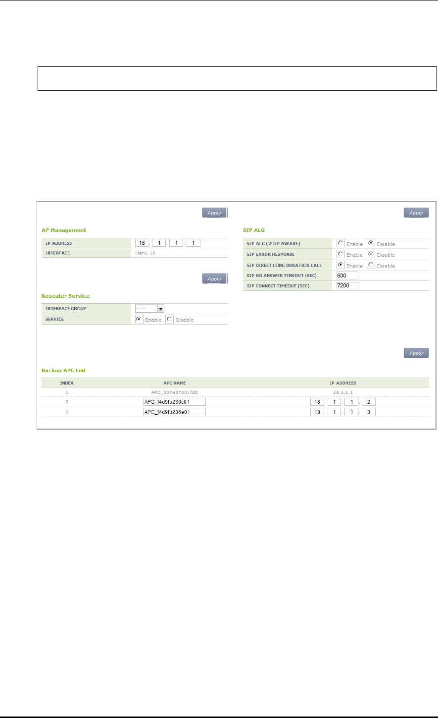
CHAPTER 7. WLAN Additional Services
© SAMSUNG Electronics Co., Ltd. page 280 of 628
2) Enable the SIP ALG.
APC/configure# sipalg enable
3) To check the configuration information, use the ‘show sipalg configuration’ command.
Configuration using Web UI
In the menu bar of <WEC Main window>, select <Configuration> and then select the
<Controller> <General> menu in the sub-menus.
Figure 137. SIP ALG configuration window
After configuring SIP ALG that is a voice CAC related configuration in the SIP ALG, click
the <Apply> button.

CHAPTER 7. WLAN Additional Services
© SAMSUNG Electronics Co., Ltd. page 281 of 628
7.3.2 Voice CAC Configuration
To protect existing calls, the voice CAC function configures maximum allowed number of
calls and rejects any call request when the maximum number is exceeded. You can
configure the number of marginal voice calls for handover.
Configuration using CLI
For voice CAC configuration, execute the command as follows:
1) Go to configure voice CAC mode of a wireless section of CLI.
APC# configure terminal
APC/configure# [80211a/80211bg] cac voice
APC/configure/80211a/cac/voice#
2) Enable or disable the voice CAC function.
acm [MODE]
Parameter
Description
MODE
Enables or disables the voice CAC function
- enable: Enable
- disable: Disable
3) Configure maximum allowed number of voice calls.
max-calls [VALUE]
Parameter
Description
VALUE
Maximum allowed number of voice calls.
4) Configure the number of marginal voice calls considering the handover.
reserved-ho-calls [VALUE]
Parameter
Description
VALUE
Number of marginal voice calls considering the handover
5) To check the configured voice CAC information, use the ‘show [80211a | 80211bg]
cac voice configuration’ command.

CHAPTER 7. WLAN Additional Services
© SAMSUNG Electronics Co., Ltd. page 282 of 628
Configuration using Web UI
In the menu bar of <WEC Main window>, select <Configuration> and then select the
<Radio> <802.11a/n> or <802.11b/g/n> <Admission Control> menu in the sub-
menus.
Figure 138. Admission control configuration of 802.11a/n
After configuring the below item in the Call Admission Control, click the <Apply> button.
ADMISSION CONTROL: Configures the CAC function.
MAX CALLS: Maximum number of allowed calls (range: 2-30)
HANDOVER CALLS: Number of marginal calls considering handover (range: 0-10)
The number of allowed calls is MAX CALLS-HANDOVER CALLS.
MINOR ALARM THRESHOLD: Configures a threshold that generates a Minor alarm
(range: 0-15)
Enter ‘0’ to prevent the alarm.
MAJOR ALARM THRESHOLD: Configures a threshold that generates a Major alarm
(range: 0-30)
Enter ‘0’ to prevent the alarm.

CHAPTER 7. WLAN Additional Services
© SAMSUNG Electronics Co., Ltd. page 283 of 628
7.3.3 Video CAC Configuration
To protect existing video calls, the video CAC function configures the maximum allowed
number of video calls and rejects any call request when the maximum number is exceeded.
You can configure the number of marginal calls for handover.
Configuration using CLI
For video CAC configuration, execute the command as follows:
1) Go to configure video CAC mode of a wireless section of CLI.
APC# configure terminal
APC/configure# [80211a/80211bg] cac video
APC/configure/80211a/cac/video#
2) Enable or disable the video CAC function.
acm [MODE]
Parameter
Description
Mode
Enables or disables the CAC function
- enable: Enable
- disable: Disable
3) Select a video CAC method.
method [method]
Parameter
Description
method
Select a video CAC method (static/chan_util)
- static: Based on video calls
- chan_util: Based on channel usage
4) Configure the maximum allowed number of calls.
max-calls [VALUE]
Parameter
Description
VALUE
Maximum allowed number of video calls
5) Configure the number of marginal calls with consideration for handover.
reserved-ho-calls [VALUE]
Parameter
Description
VALUE
Number of marginal calls with consideration for handover
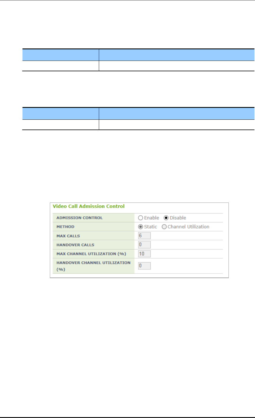
CHAPTER 7. WLAN Additional Services
© SAMSUNG Electronics Co., Ltd. page 284 of 628
6) Configure the maximum allowed usage of channels.
max-chan-util [VALUE]
Parameter
Description
VALUE
Maximum allowed usage of channels
7) Configure the usage of marginal channels with consideration for handover.
reserved-ho-chan-util [VALUE]
Parameter
Description
VALUE
Usage of marginal channels with consideration for handover
8) You can view the video CAC information you configured by executing the ‘show
[80211a | 80211bg] cac video configuration’ command.
Configuration using Web UI
From the menu bar of <WEC Main Window>, select <Configuration> and then select
<Radio> <802.11a/n> or <802.11b/g/n> <Admission Control> in the submenus.
Figure 139. 802.11a/n Admission Control Configuration Window
After configuring the items below in the Call Admission Control, click the <Apply> button.
ADMISSION CONTROL: Configure the video CAC function
METHOD: Select a video CAC method (static/chan_util)
MAX CALLS: Maximum allowed number of calls (range: 2-30)
HANDOVER CALLS: Number of marginal calls with consideration for handover
(range: 0-8)
The maximum allowed number of calls becomes MAX CALLS-HANDOVER CALLS.
MAX CHANNEL UTILIZATION (%): Maximum allowed usage of channels (range: 5-85)
HANDOVER CHANNEL UTILIZATION (%): Usage of marginal channels with
consideration for handover (range: 0-25)

CHAPTER 7. WLAN Additional Services
© SAMSUNG Electronics Co., Ltd. page 285 of 628
7.4 Radio Resource Management (RRM)
RRM performs automatic setup function for AP’s channel and Tx Power. RRM is
functionally divided into Dynamic Channel Selection (DCS), Dynamic Power control
(DPC), and Coverage Hole Detection and Control (CHDC). The DCS automatically sets
the channels of the APs. The DPC DCS automatically sets the Tx Power of the AP.
The CHDC adjusts the Tx Power when Coverage Hole occurs.
7.4.1 RRM Configuration
This section describes the settings for using the RRM function and the cluster configuration.
Configuration using CLI
To configure each function, execute the command as follows:
1) Go to configure rrm configuration mode of CLI.
WEC8500# configure terminal
WEC8500/configure# rrm
2) Enable RRM. The ‘no’ parameter is used to disable RRM. DCS, DPC and CHDC,
which are functions of RRM, can run only if the RRM is enabled.
WEC8500/configure/rrm# enable
3) In the cluster environment, set the same RF Group Name to all the connected APCs.
A name must consist of up to 15 characters.
WEC8500/configure/rrm# rf-group-name [Name]
4) Configure priorities between the neighbor list of each Wlan. Go to the wireless section
the configuration of which you want to change and then enter neighbor-list setup mode.
You can select between rssi and handover, and the default value is rssi.
WEC8500/configure/rrm# 80211a
WEC8500/configure/rrm/80211a# neighbor-list
WEC8500/configure/rrm/80211a/neighbor-list# wlan-neighbor-priority
rssi/handover
5) To check the configured information, use the ‘show rrm config-summary’ command.

CHAPTER 7. WLAN Additional Services
© SAMSUNG Electronics Co., Ltd. page 286 of 628
Configuration using Web UI
In the menu bar of <WEC Main window>, select <Configuration> and then select the
<Radio> <802.11a/n/ac> or <802.11b/g/n> <RRM> menu in the sub-menus.
Enable or disable the RRM service at the top of the menu. The RRM can be set in either
802.11a/n/ac screen or 802.11b/g/n screens. Configure priorities between the neighbor list
of each Wlan at the bottom of the menu.
Figure 140. RRM configuration window
7.4.2 DPC Configuration
This section describes the setting options of the DPC function which automatically sets the
Tx Power of the AP.
Configuration using CLI
1) Go to configure rrm configuration mode of CLI.
WEC8500# configure terminal
WEC8500/configure# rrm
2) Go to the wireless section where you want to change the settings.
WEC8500/configure/rrm# 80211a
3) Set the DPC function. Enter the dpc setting mode and set it to ‘enable’. Use the ‘no’
parameter to disable the mode. The function operates only when the RRM is set to
Enable.
WEC8500/configure/rrm/80211a# dpc
WEC8500/configure/rrm/80211a/dpc# enable
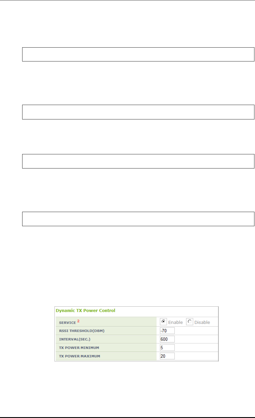
CHAPTER 7. WLAN Additional Services
© SAMSUNG Electronics Co., Ltd. page 287 of 628
4) Execute the following command to change the Received Signal Strength Indication
(RSSI) threshold for neighbor AP. The default value is -70 (dBm).
WEC8500/configure/rrm/80211a/dpc# rssi-threshold [value]
5) If you need to change the RSSI threshold for the station, execute the following command.
The default value is -70 (dBm). This parameter is used only in the DCS-DPC joint
algorithm.
WEC8500/configure/rrm/80211a/dpc# rssi-threshold-for-stn [value]
6) Execute the following command to change the execution interval. The default value is
600 (seconds).
WEC8500/configure/rrm/80211a/dpc# periodic-interval [value]
7) Execute the following command to change the Tx Power range which is automatically
set by DPC. The default minimum is 16 for 80211a and 12 for 80211b.
The default maximum is 20 for both 80211a and 80211b.
WEC8500/configure/rrm/80211a/dpc# txPower min [value] max [value]
8) Check the settings using the ‘show rrm config-summary’ command.
Configuration using Web UI
In the menu bar of <WEC Main window>, select <Configuration> and then select the
<Radio> <802.11a/n/ac> or <802.11b/g/n> <RRM> menu in the sub-menus.
Enable or disable the DPC in the SERVICE field in Dynamic TX Power Control.
Figure 141. DPC settings

CHAPTER 7. WLAN Additional Services
© SAMSUNG Electronics Co., Ltd. page 288 of 628
7.4.3 DCS Configuration
This section describes the setting options of the DCS function which automatically sets the
channel of the AP.
Configuration using CLI
1) Go to configure rrm configuration mode of CLI.
WEC8500# configure terminal
WEC8500/configure# rrm
2) Go to the wireless section where you want to change the settings.
WEC8500/configure/rrm# 80211a
3) Set the DCS function. Enter the dcs setting mode and set it to ‘enable’. Use the ‘no’
parameter to disable the mode. The function operates only when the RRM is set to
Enable.
WEC8500/configure/rrm/80211a# dcs
WEC8500/configure/rrm/80211a/dcs# enable
4) Configure whether to apply the DCS-DPC joint algorithm. If the ‘no’ parameter is
selected, the configuration is cleared.
WEC8500/configure/rrm/80211a/dcs# joint-algo-enable
5) Execute the following command to change the execution interval. The default value is
120 (seconds).
WEC8500/configure/rrm/80211a/dcs# periodic-interval [value]
6) Execute the following command to change the Channel Utilization threshold.
The default value is 80 (%).
WEC8500/configure/rrm/80211a/dcs# channel-utilization-threshold [value]
7) Execute the following command to change the My Utilization threshold.
The default is 10 (%) for 802.11a and 40 (%) for 802.11b.
WEC8500/configure/rrm/80211a/dcs# my-utilization-threshold [value]

CHAPTER 7. WLAN Additional Services
© SAMSUNG Electronics Co., Ltd. page 289 of 628
8) Execute the following command to set the anchor time. The default value is start time
4, end time 5. If both start time and end time are set to the same time, Anchor Run
function is disabled.
WEC8500/configure/rrm/80211a/dcs# anchor-time start [value] end [value]
9) Execute the following command to change the channels that is automatically set by the
DCS. Use the ‘no’ parameter to disable the mode.
WEC8500/configure/rrm/80211a/dcs# channel [value]
10) Execute the following command to use the Delayed Channel Change function.
To disable the configuration, enter the ‘no’ parameter. The default is Disable.
The Delayed Channel Change function delays channel change instead of changing it
immediately when a channel becomes busy due to channel utilization. If the anchor
time is not configured, the default value is used at 4 o’clock.
WEC8500/configure/rrm/80211a/dcs# delayed-channel-change
11) To use the Aware Option function, execute the following command. To disable the
configuration, enter the ‘no’ parameter. The Aware Option does not change a channel if
there is a specific condition. Therefore, three functions are provided based on whether
there is a voice, the association of a station, or traffic in a station. The default is that
only the Voice Aware function is enabled. The Station Aware function specifies the
number of stations at the same time.
WEC8500/configure/rrm/80211a/dcs# aware-option voice
WEC8500/configure/rrm/80211a/dcs# aware-option station [station count]
WEC8500/configure/rrm/80211a/dcs# aware-option traffic
12) Check the settings using the ‘show rrm config-summary’ command.
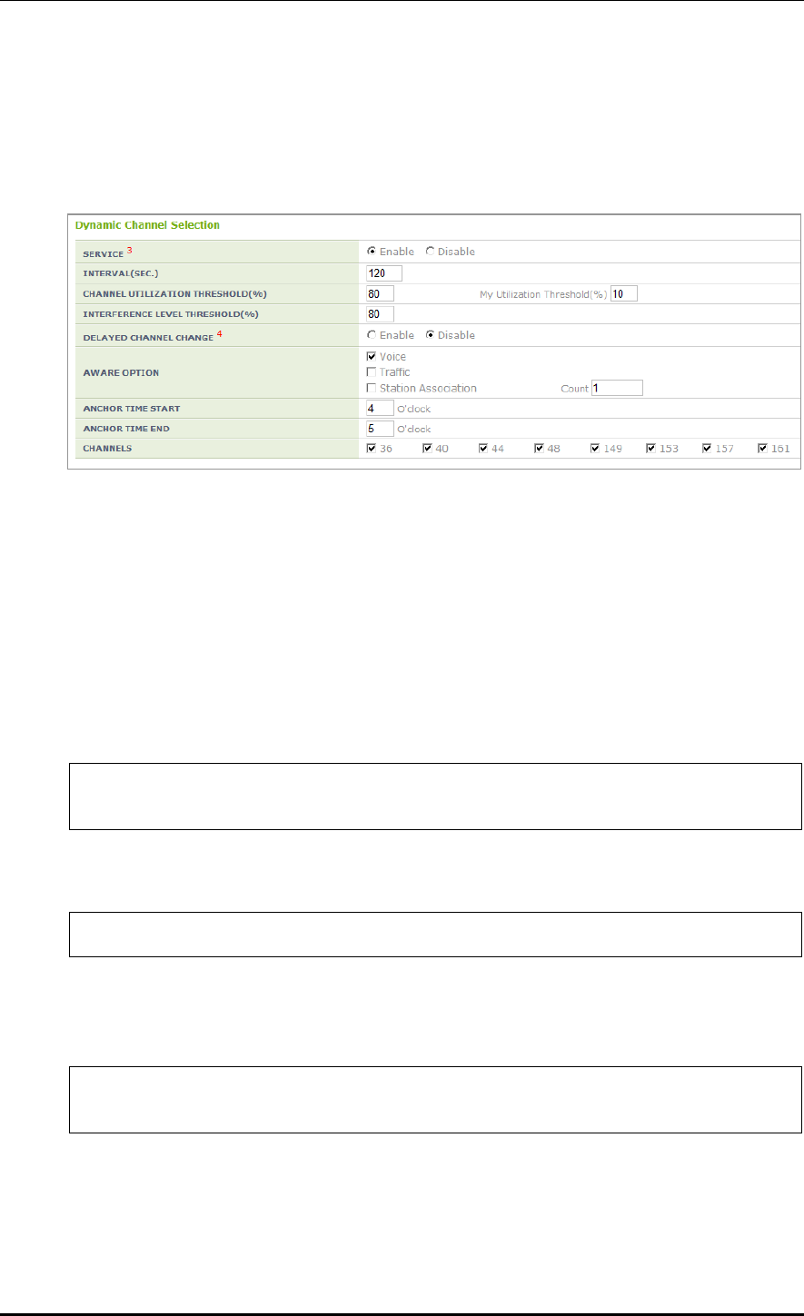
CHAPTER 7. WLAN Additional Services
© SAMSUNG Electronics Co., Ltd. page 290 of 628
Configuration using Web UI
In the menu bar of <WEC Main window>, select <Configuration> and then select the
<Radio> <802.11a/n/ac> or <802.11b/g/n> <RRM> menu in the sub-menus.
Enable or disable the DCS in the SERVICE field in Dynamic Channel Selection.
Figure 142. DCS settings
7.4.4 CHDC Configuration
This section describes the setting options of the CHDC function which adjusts the Tx
Power when Coverage Hole occurs.
Configuration using CLI
1) Go to configure rrm configuration mode of CLI.
WEC8500# configure terminal
WEC8500/configure# rrm
2) Go to the wireless section where you want to change the settings.
WEC8500/configure/rrm# 80211a
3) Set the CHDC function. Enter the chdc setting mode and enable it Use the ‘no’
parameter to disable the mode. The function operates only when the RRM is enabled.
WEC8500/configure/rrm/80211a# chdc
WEC8500/configure/rrm/80211a/chdc# enable
4) To use the pre-alarm function, operator can collect the statistics from an AP.
After entering into the chdc configuration mode, complete configuration
(statsCollectEnable). To disable the configuration, enter the ‘no’ parameter. All the
functions for pre-alarm are available only when both RRM and CHDC are enabled.

CHAPTER 7. WLAN Additional Services
© SAMSUNG Electronics Co., Ltd. page 291 of 628
WEC8500/configure/rrm/80211a/chdc# statsCollectEnable
Success: DBI set for DPC 11A Stats collect Enable : 1
5) If a coverage hole is estimated from the statistics for the pre-alarm function, a warning
can be transmitted. After entering into the chdc configuration mode, complete
configuration (statsWarningEnable). To disable the configuration, enter the ‘no’
parameter.
WEC8500/configure/rrm/80211a/chdc# statsWarningEnable
Success: DBI set for DPC 11A Stats Warning Enable : 1
6) If a coverage hole is estimated from the statistics for the pre-alarm function, CHDC
can be executed. After entering into the chdc configuration mode, complete
configuration (statsActionEnable). To disable the configuration, enter the ‘no’
parameter.
WEC8500/configure/rrm/80211a/chdc# statsActionEnable
Success: DBI set for DPC 11A Stats Action Enable : 1
7) Configure the minimum value of statistics Failed Client Count for the pre-alarm function.
It can be 1~75.
WEC8500/configure/rrm/80211a/chdc# min-failed-client-count 70
CHDC 802.11a : Set Minimum Failed Client Count Success
8) Configure the percentage of statistics Failed Client Count for the pre-alarm function.
It can be 10~35.
WEC8500/configure/rrm/80211a/chdc# percent-failed-client-count 20
Success: CHDC 802.11a : Set Percentage of Failed Client Count Success
9) Configure the threshold of RSSI that will be added to the statistics Failed Client Count
for the pre-alarm function. Configure it for Voice Frame and Data Frame. It can be -
90~-20 (dB).
WEC8500/configure/rrm/80211a/chdc# rssi-threshold data -75
Success: CHDC 802.11a : Set RSSI THRESHOLD(-75) Successful
WEC8500/configure/rrm/80211a/chdc# rssi-threshold voice -75
Success: CHDC 802.11a : Set RSSI THRESHOLD(-75) Successful

CHAPTER 7. WLAN Additional Services
© SAMSUNG Electronics Co., Ltd. page 292 of 628
10) Configure a value that requests an interval to an AP to collect statistics for the pre-
alarm function. The default is 120 seconds and it can be 30~3600 seconds.
WEC8500/configure/rrm/80211a/chdc# statsCollectInterval 60
This Value: 60 is already set
11) Configure the minimum value of the idle time-out count of statistics for the pre-alarm
function. This parameter can have a value ranging from 0 to 1,000.
WEC8500/configure/rrm/80211a/chdc# min-idle-timeout-count 10
CHDC : Set Minimum IdleTimeOutCnt Success
12) To check the configured information, execute the ‘show rrm config-summary’
command. In the ‘Coverage Hole Detection and Control’, operator can check the
current status of all the configured values.
WEC8500/configure/rrm/80211a/chdc# show rrm config-summary
RRM Status ..... Enabled
Rf Group Name ... Group
80211a/n 80211b/g/n
Dynamic Power Control ----------------------- -----------------
DPC Enable .. Enabled Enabled
Periodic Interval .. follow DCS follow DCS
RSSI Threshold for Neighbor AP .. -70 -70
RSSI Threshold for Station .. -70 -70
TX Power Min. - Max. .. 17 - 20 14 - 20
Minimum Number of AP .. 2 2
Elapsed Time After Last Run .. 36 7
Dynamic Channel Selection ------------------- -----------------
DCS Enable .. Enabled Enabled
DCS-DPC Joint Algorithm Enable .. Enabled Enabled
Periodic Interval .. 60 60
Anchor Time Start .. 0 0
Anchor Time Stop .. 23 23
Interference Level Threshold .. 80 80
Channel Utilization Threshold .. 99 99
My Utilization Threshold .. 10 40
Delayed Channel Change .. Enabled Enabled
Aware-Option: Voice Call .. Enabled Enabled
Aware-Option: Traffic .. Enabled Enabled
Aware-Option: Station Assoc. .. Enabled Enabled
Station Count for Station Aware .. 1 1
Elapsed Time After Last Run .. 36 7
Coverage Hole Detection and Control --------- -----------------
CHDC Enable .. Enabled Enabled
Statistics Collect Enable .. Enabled Enabled
Statistics Warning Enable .. Enabled Enabled
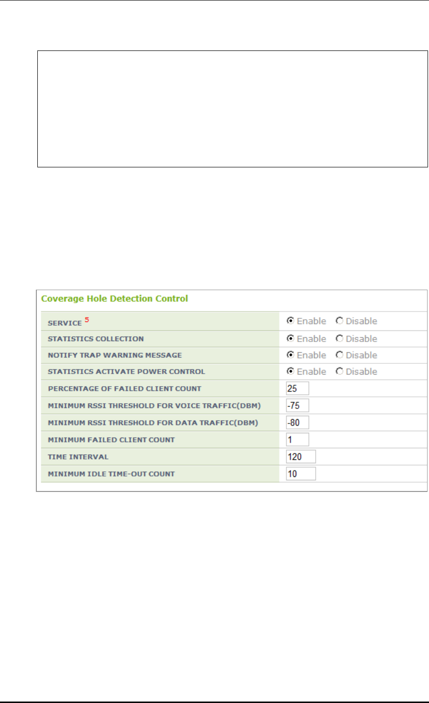
CHAPTER 7. WLAN Additional Services
© SAMSUNG Electronics Co., Ltd. page 293 of 628
Statistics Action Enable .. Enabled Enabled
RSSI Voice Threshold .. -75 -75
RSSI Data Threshold .. 80 -30
Minimum Failed Client Count .. 1 1
Percentage Min. Failed Count .. 25 25
Minimum Idle time-out Count .. 10 10
Statistics Collect Interval .. 120 60
Neighbor List Management -------------------- -----------------
WLAN Neighbor Priority .. Handover Handover
Configuration using Web UI
In the menu bar of <WEC Main window>, select <Configuration> and then select the
<Radio> <802.11a/n/ac> or <802.11b/g/n> <RRM> menu in the sub-menus.
In the Coverage Hole Detection Control window, operator can enable or disable the CHDC
and configure the values using the same functions as the CLI.
Figure 143. CHDC settings

CHAPTER 7. WLAN Additional Services
© SAMSUNG Electronics Co., Ltd. page 294 of 628
7.4.5 Sleeping Cell Detection
This is a function that allows the APC to detect the statuses of APs that are not performing
basic functions and transmit an alarm/warning.
Configuration using CLI
1) Enable/Disable: Configure whether the silent alarm detection function will be performed.
(Enable: function performing, Disable: function not performing)
WEC8500/configure/rrm# sleep-cell-detect
WEC8500/configure/rrm/sleep-cell-detect# enable
2) APC Threshold: Minimum number of connected users throughout the whole APC for
sleeping cell detection.
If the total number of STA associations is equal to or smaller than the APC threshold,
the day is judged as a holiday and consequently the sleeping cell detection is not
performed.
WEC8500/configure/rrm/sleep-cell-detect# apc-threshold
3) AP Threshold: Minimum number of users connected to an AP for sleeping cell detection.
If the number of STA associations of an AP is equal to or smaller than the AP threshold,
a silent alarm occurs.
WEC8500/configure/rrm/sleep-cell-detect# ap-threshold
4) PERIOD_1ST: Start and end times of sleeping cell detection for Specific Period 1.
(For a full day, set the start and end times as the same time.)
WEC8500/configure/rrm/sleep-cell-detect# period_1st
5) PERIOD_2ND: Start and end times of sleeping cell detection start for Specific Period 2.
(For a full day, set the start and end times as the same time.)
WEC8500/configure/rrm/sleep-cell-detect# period_2nd
6) PERIOD_ALL: Start and end times of sleeping cell detection for periods other than
Specific Periods 1 and 2.
WEC8500/configure/rrm/sleep-cell-detect# period_all
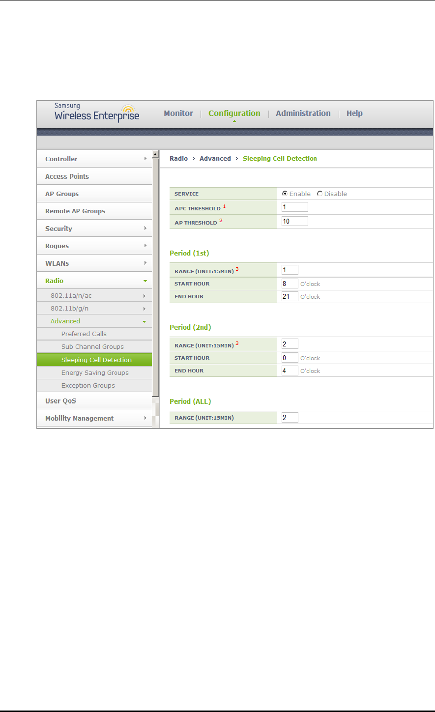
CHAPTER 7. WLAN Additional Services
© SAMSUNG Electronics Co., Ltd. page 295 of 628
Configuration using Web UI
From the menu bar of <WEC Main Window>, select <Configuration> and then select
<Radio> <Advanced> <Sleeping Cell Detection> in the submenus.

CHAPTER 7. WLAN Additional Services
© SAMSUNG Electronics Co., Ltd. page 296 of 628
7.4.6 Energy Saving Groups
The purpose is to reduce the power consumption of the APC by turning off the RF
radios of APs without any connected STA at a specific time when the number of STAs
connected to the APC drops drastically.
The APs of the APC are divided into the active group in which APs are always in
operation and the standby group in which the RF radios of APs are turned off.
When the standby group (energy saving group) is defined, the APC recognizes the
remaining APs as the active group. You can define up to 10 groups.
Configuration using CLI
1) Enable/Disable: Configure whether the energy saving function will be performed.
(Enable: function performing, Disable: function not performing)
WEC8500/configure/rrm# energy-saving-group 1
WEC8500/configure/rrm/energy-saving-group 1# enable
2) APC Threshold: Maximum number of connected users throughout the whole APC for
energy saving detection.
If the total number of STA associations is equal to or smaller than the APC threshold,
the day is judged as a holiday and the energy saving function is performed according
to the times set for weekends.
WEC8500/configure/rrm/energy-saving-group 1# apc-threshold
3) WEEKDAY: Start and end times of energy saving for weekdays.
(For a full day, set the start and end times as the same time.)
WEC8500/configure/rrm/energy-saving-group 1# weekday
4) WEEKDEND: Start and end times of energy saving for weekends.
(For a full day, set the start and end times as the same time.)
WEC8500/configure/rrm/energy-saving-group 1# weekend
5) ADD-AP: Add AP members to the energy saving group.
WEC8500/configure/rrm/energy-saving-group 1# add-ap
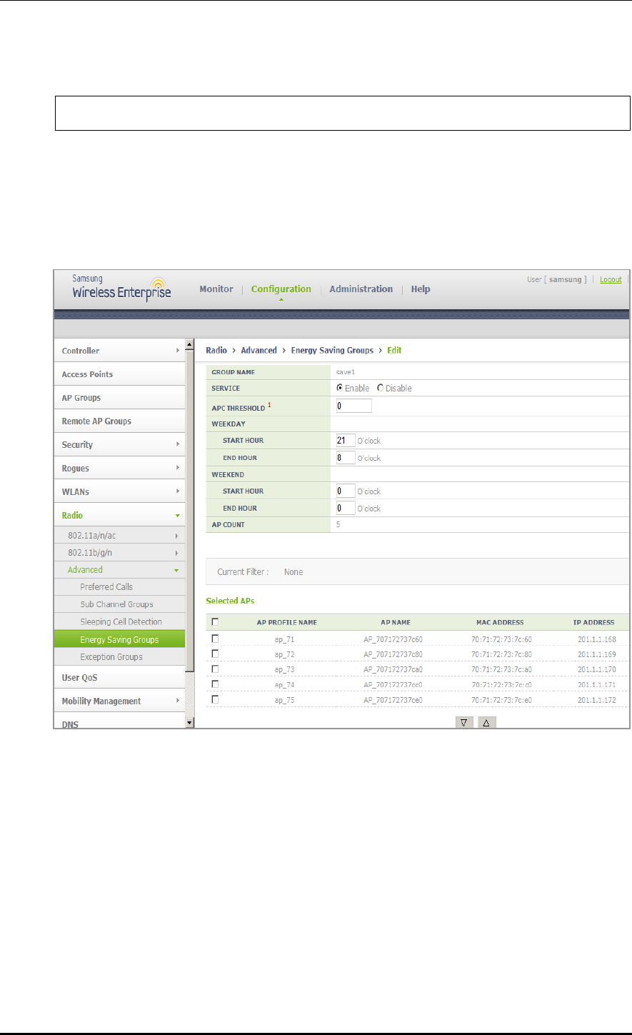
CHAPTER 7. WLAN Additional Services
© SAMSUNG Electronics Co., Ltd. page 297 of 628
6) DEL-AP: Delete AP members from the energy saving group.
WEC8500/configure/rrm/energy-saving-group 1# del-ap
Configuration using Web UI
From the menu bar of <WEC Main Window>, select <Configuration> and then select
<Radio> <Advanced> <Energy Saving Groups> <GROUP NAME> in the
submenus.
7.4.7 Energy Saving Auto Classification
The purpose of the AP without the connected STA at a specific time when the STA
connected to the APC is drastically reduced is to reduce power consumption of the APC by
turning off the RF radio of the AP.
The APs of the APC are classified into an active group to keep them at the operational
status all the time and a standby group to make their RF radio off at the designated time.
When the APC designates a standby group (energy saving group), the others are recognized
as an active group.

CHAPTER 7. WLAN Additional Services
© SAMSUNG Electronics Co., Ltd. page 298 of 628
Up to 20 groups can be designated (Same as WEC8500/WEC8050).
Energy Saving Auto Classification is not a method under which the operator configures a
standby group but a method under which the system automatically classifies an energy
saving group by using the analysis of each AP.
For the convenience of the operator, the existing Energy Saving Groups and Energy Saving
Auto Classification functions can be used by mixture. In short, as shown in the existing
method, only Energy Saving Groups or only Energy Saving Auto Classification or both can
be used.
Configuration using CLI
1) Enable/Disable: Check the configuration of whether the Energy Saving Auto
Classification function operates.
(Enable: Function operation, Disable: No function operation)
WEC8500/configure/rrm# energy-saving-auto-class
WEC8500/configure/rrm/energy-saving-auto-class# enable
2) APC Threshold: The maximum number of all users connecting to the APC for Energy
Saving Auto Classification
If the number of all STA associations is less than APC threshold, the day is considered
as a holiday and the Energy Saving Auto Classification function operates depending
on the weekend setting time.
WEC8500/configure/rrm/energy-saving-auto-class# apc-threshold
3) WEEKDAY: Energy saving start/end time on a weekday
(For all day, the start time and the end time are set to the same time.)
WEC8500/configure/rrm/energy-saving-auto-class# weekday
4) WEEKDEND: Energy saving start/end time on a weekend
(For all day, the start time and the end time are set to the same time.)
WEC8500/configure/rrm/energy-saving-auto-class# weekend
5) UNCONDITIONAL RADIO OFF: Configure whether the AP radio is turned off
unconditionally, regardless of the connection of the STA.
(radio_off_unconditionally: Unconditionally off, no radio_off_unconditionally: If the
STA is connected, keep the state ON.)
../configure/rrm/energy-saving-auto-class# radio_off_unconditionally
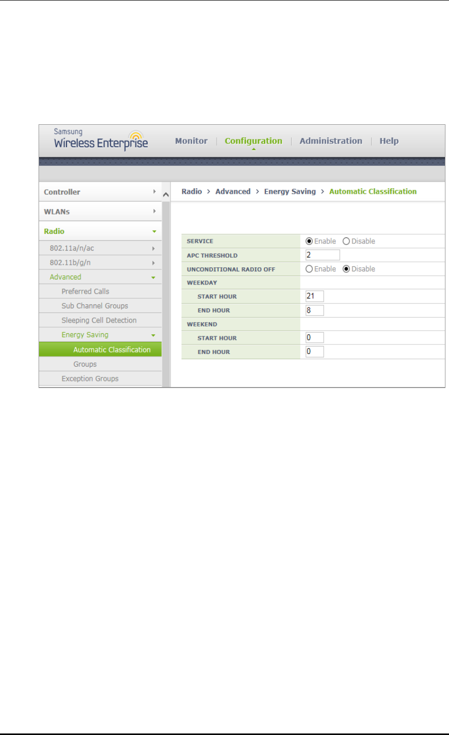
CHAPTER 7. WLAN Additional Services
© SAMSUNG Electronics Co., Ltd. page 299 of 628
Configuration using Web UI
In the menu bar of <WEC Main window>, select <Configuration> and then select
<Radio> <Advanced> <Energy Saving> <Automatic Classification> menus in
the sub-menus.

CHAPTER 7. WLAN Additional Services
© SAMSUNG Electronics Co., Ltd. page 300 of 628
7.5 Location Tracking
The APC tracks the location information of several terminals in a wireless LAN network
based on the wireless data collected from W-EP wireless LAN APs.
To configure the location tracking function, execute the command as follows:
1) Go to configure locationtrack configuration mode of CLI.
WEC8500# configure terminal
WEC8500/configure # locationtrack
WEC8500/configure/locationtrack #
2) Configure the location tracking function.
WEC8500/configure/locationtrack # enable
3) To check the configured information, execute the ‘show locationtrack config’ command.
WEC8500/configure/locationtrack # show locationtrack config
Location tracking enable....: Enabled
Algorithm type..............: 4
Expiry date of history files: 0
4) Configure the MAC address of a wireless terminal for which the tracking function will
be executed.
station [MAC_ADDRESS]
5) To check the location information of a wireless terminal to track, execute the ‘show
locationtrack station’ command.
WEC8500/configure/locationtrack # show locationtrack station
No. stationId station_MAC_Addr ap_MAC_Addr (staX,staY)
lastTime(+)
---- --------- ----------------- ----------------- ----------------- -
-------------------
1 1 f4:d9:fb:34:20:60 f4:d9:fb:34:20:60 (2432,1947)
0(1374022070)