Samsung Electronics Co WEA463E WLAN Access Point User Manual Model Name Manual Name
Samsung Electronics Co Ltd WLAN Access Point Model Name Manual Name
UserManual.wiki
>
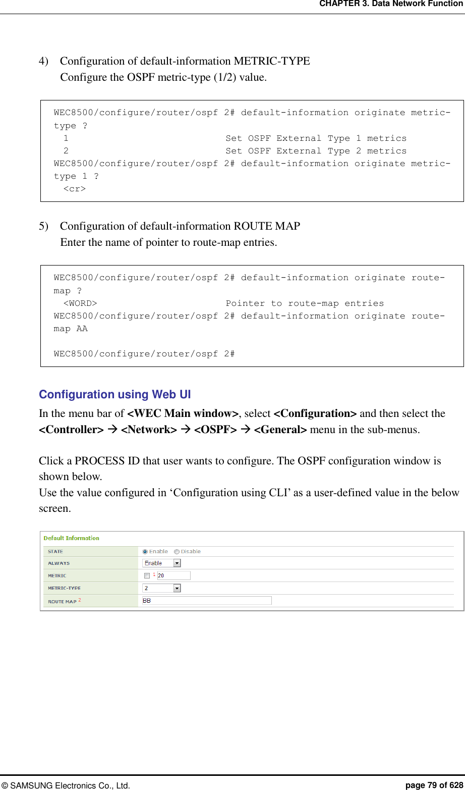
Samsung Electronics Co
>
WEA463E User Manual
>
Part 1
Contents
1.
Part 1
2.
Part 2
3.
User Manual
4.
APC Manual 1
5.
APC Manual 2
Part 1
Navigation menu
Upload a User Manual
Namespaces
Wiki Guide
HTML
PDF
Info
Views
User Manual
Discussion / Help
Navigation
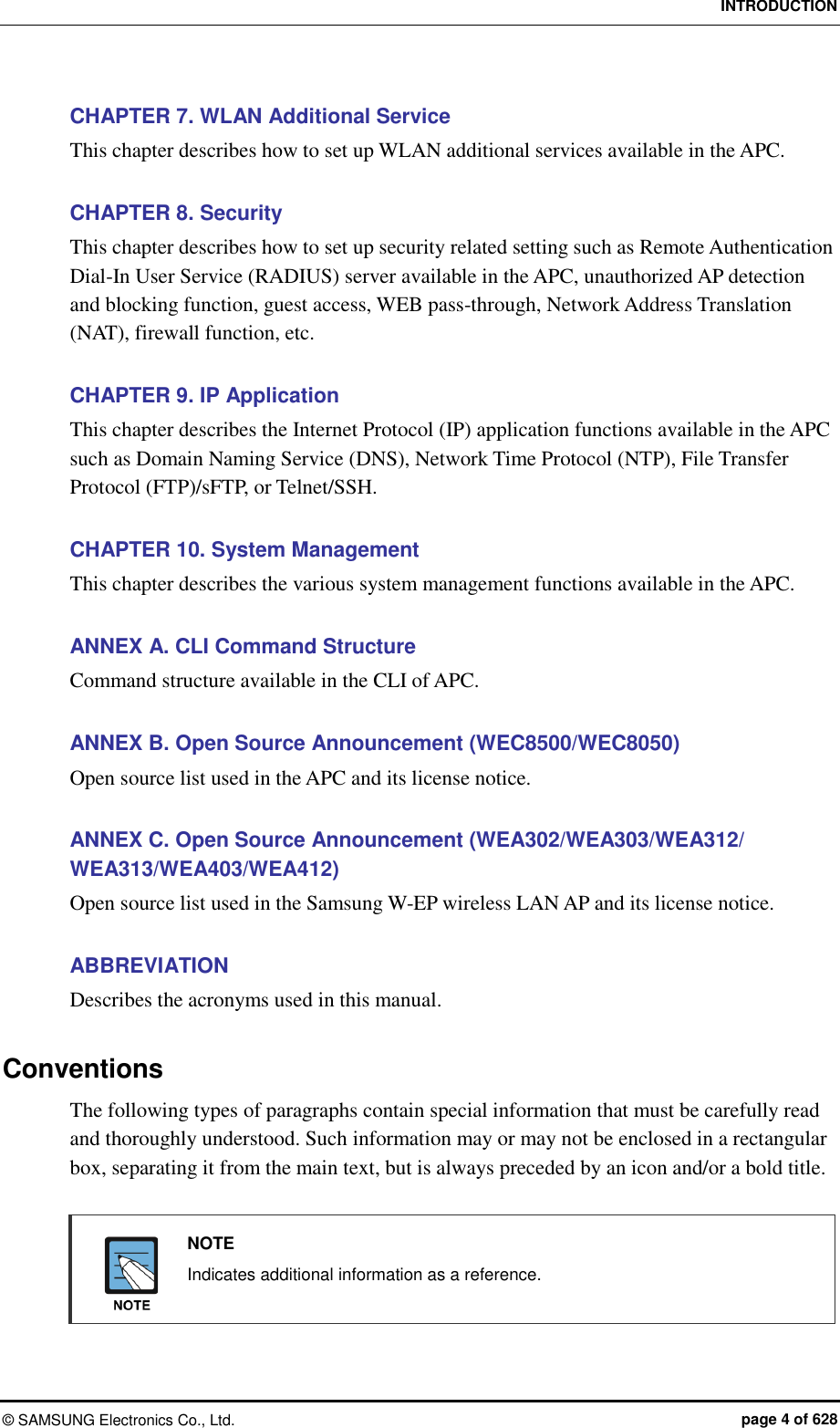
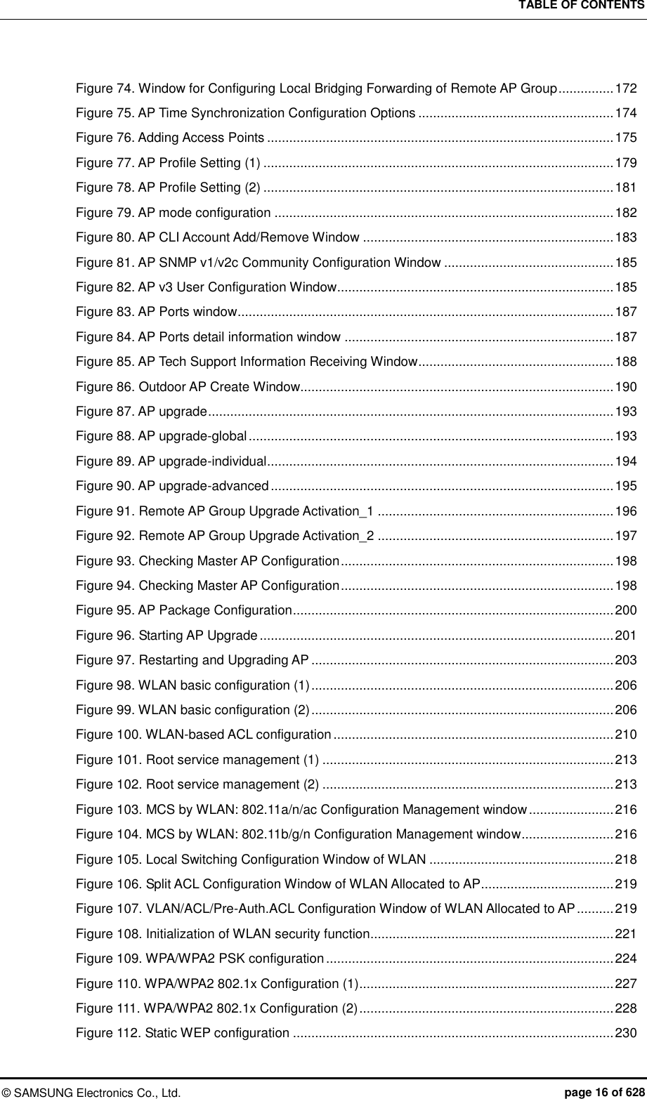
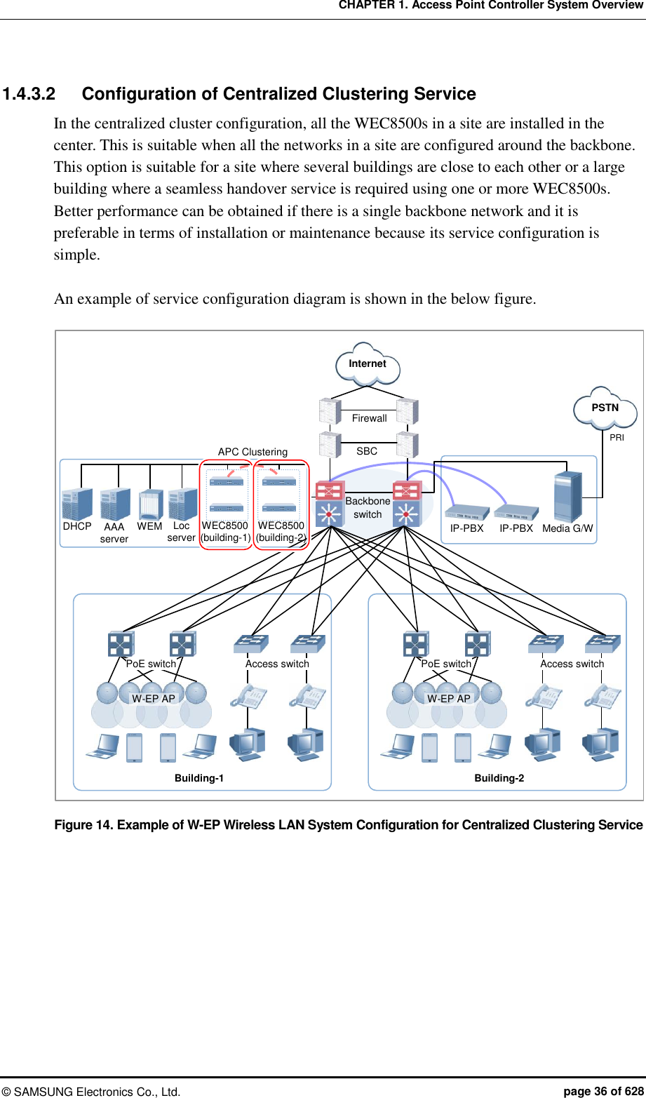
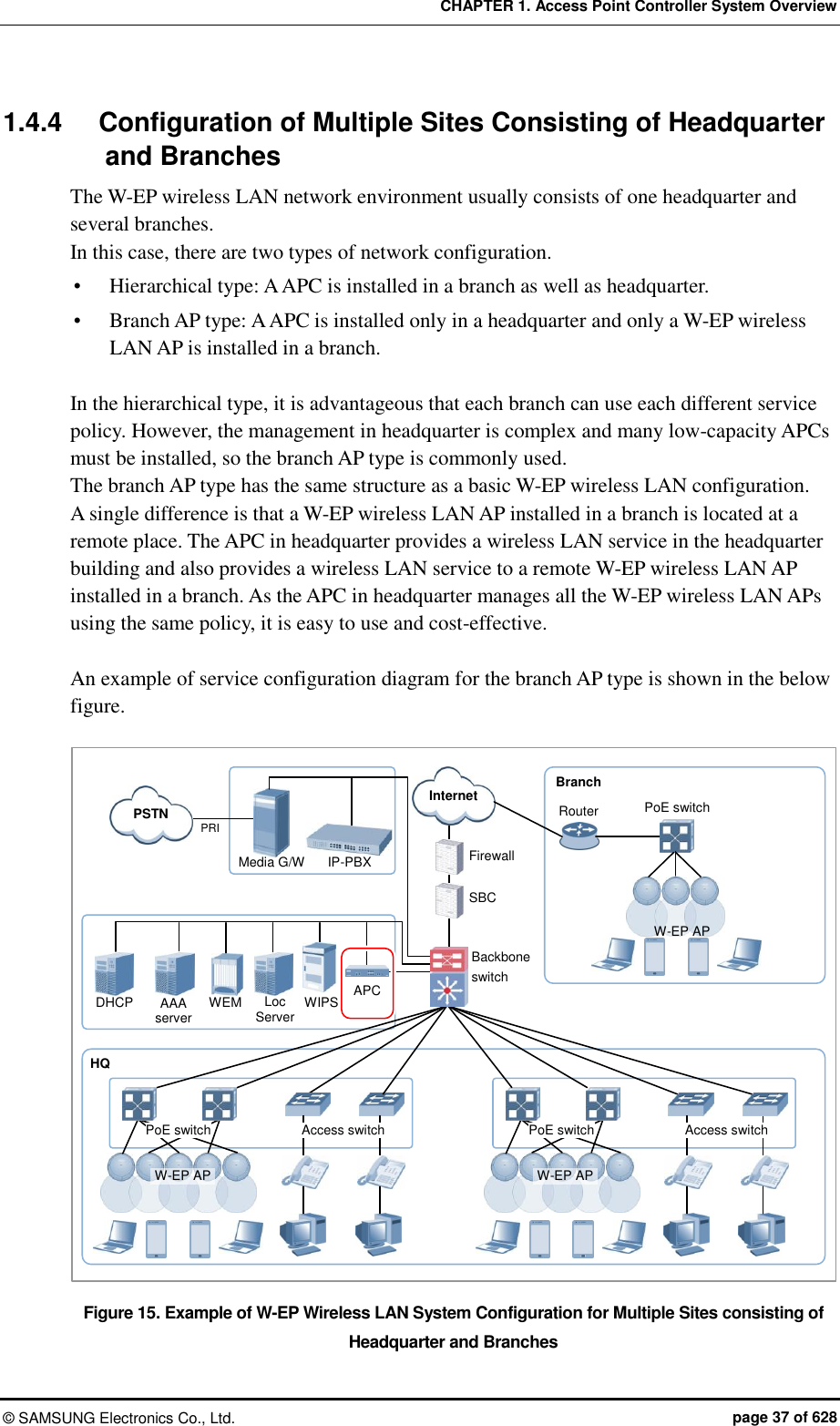

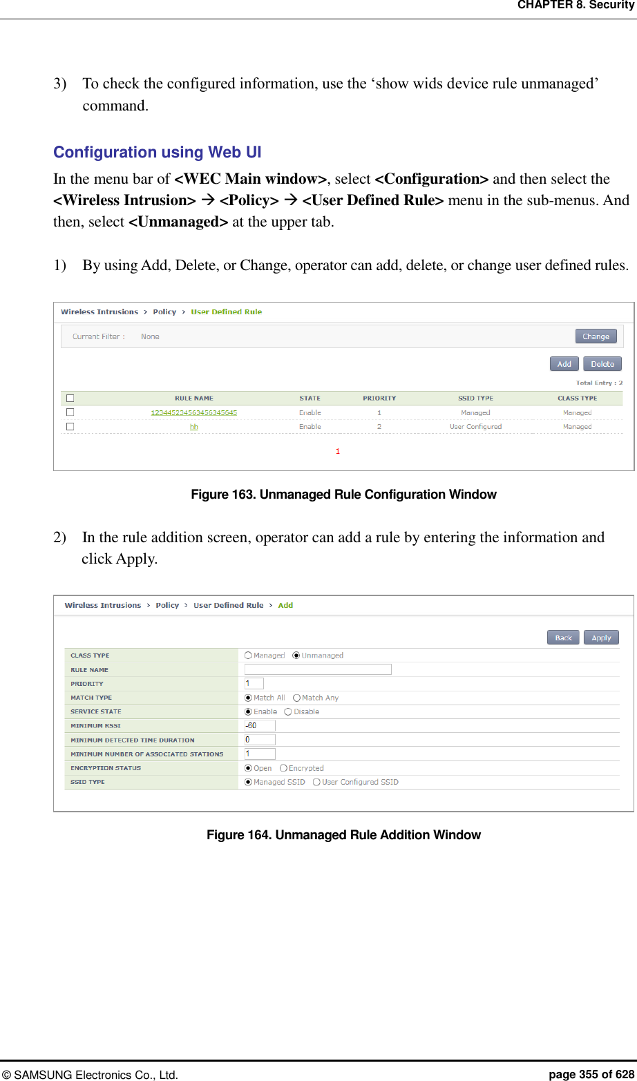
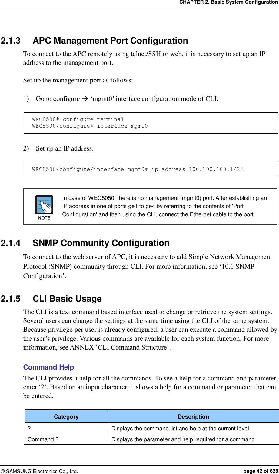
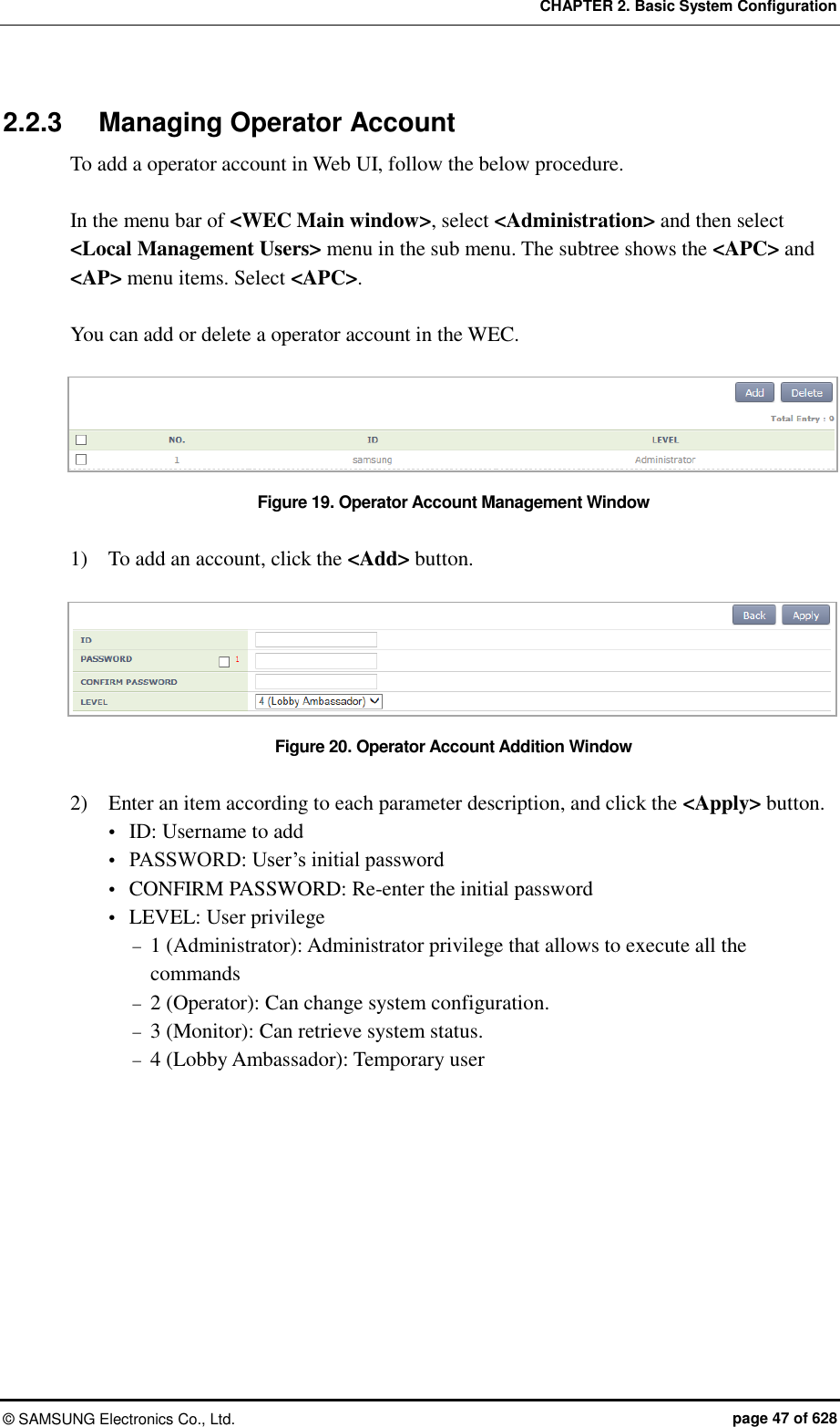
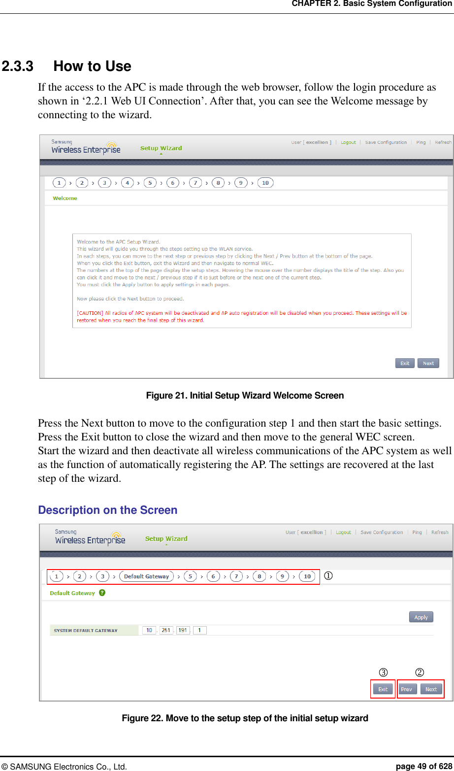
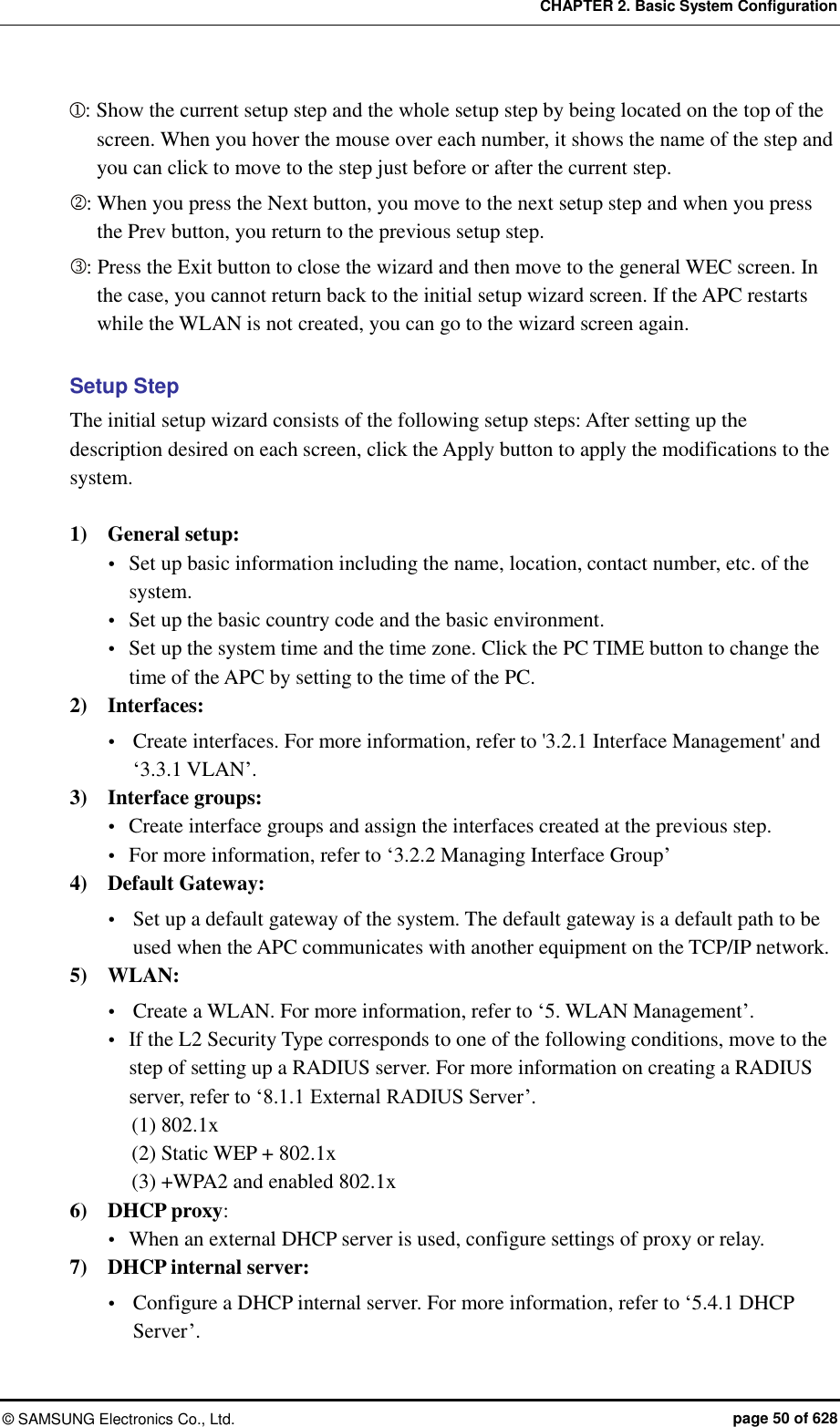
![CHAPTER 2. Basic System Configuration © SAMSUNG Electronics Co., Ltd. page 41 of 628 2.1.2 Managing Operator Account An operator who has an administrator privilege (level 1) can create or delete a new operator account. When creating an account, specify the account’s privilege level (level 1-4). To set up operator account related functions, go to configure mode by executing the following command. WEC8500# configure terminal WEC8500/configure # Adding or deleting an account The commands used to create or delete an account are as follows: mgmt-user [USERNAME] [USERLEVEL] description [DESCRIPTION]: Adds a user no mgmt-user [USERNAME]: Deletes a user Parameter Description USERNAME User ID USERLEVEL User level DESCRIPTION Adds user information WEC8050/configure# mgmt-user test 1 description “test account” PASSWORD : ********* CONFIRM PASSWORD : ********* USER(test) CREATED. WEC8050/configure# no mgmt-user test user(test) deleted. Retrieving account information To check user account information use the ‘show mgmt-users’ command. Changing Password Use the ‘password’ command to change the password for your account. The ‘password’ command must be executed in the highest user mode. WEC8500# password CURRENT PASSWORD : ******** NEW PASSWORD : ******** CONFIRM NEW PASSWORD : ********](https://usermanual.wiki/Samsung-Electronics-Co/WEA463E.Part-1/User-Guide-2696662-Page-41.png)
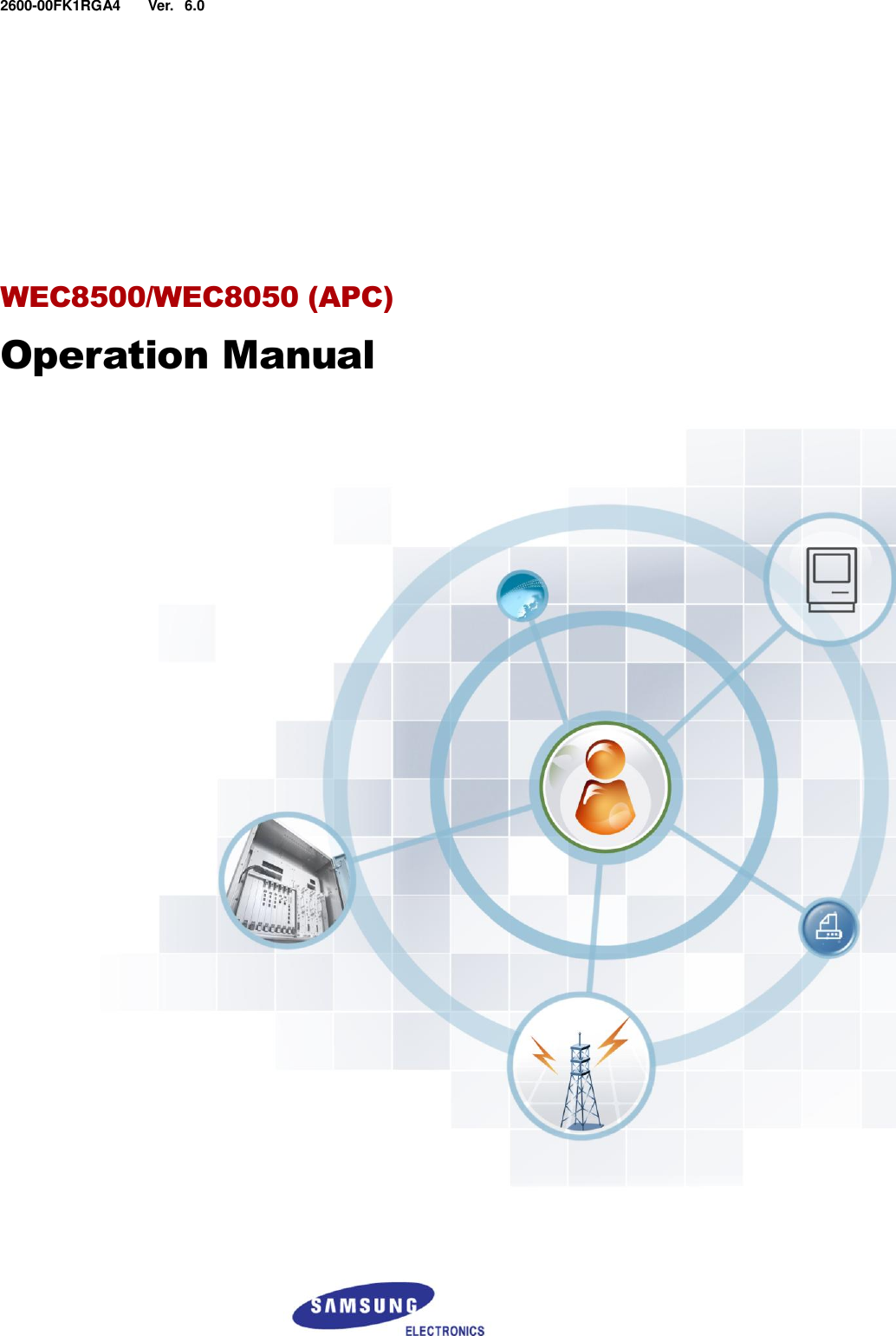
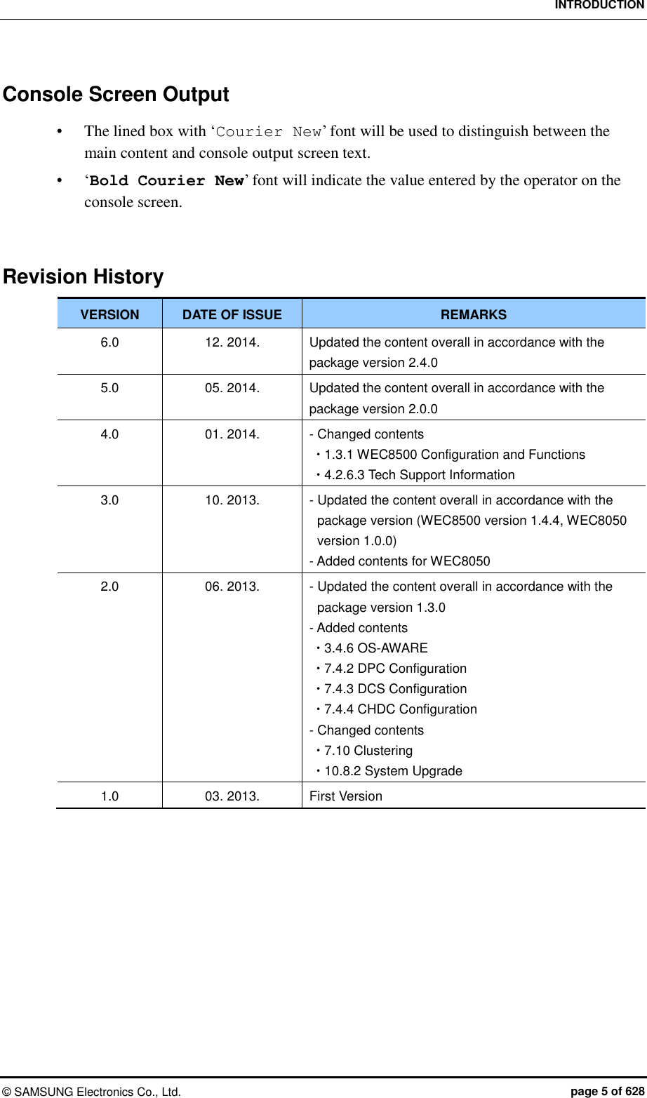
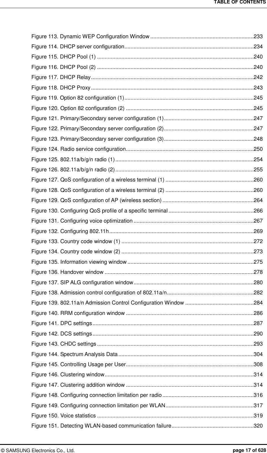
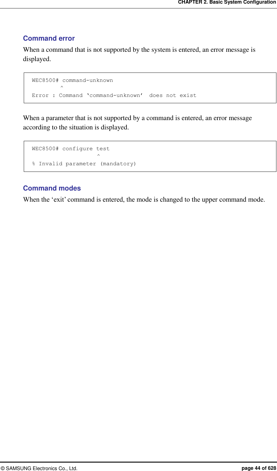
![CHAPTER 2. Basic System Configuration © SAMSUNG Electronics Co., Ltd. page 43 of 628 A usage example is given below. WEC8500# show ? 80211a Display 802.11a network settings 80211bg Display 802.11bg network settings 80211h Display 802.11h configuration access-list List IP access lists alarm Show alarm information ap Show ap information ap-debug Show ap debug information ... vap Show vap information version Show package version information vlan Display VLAN information vqm Show vqm command vrrp VRRP information wids Wids command wips Wips command wireless-acl-list Show wireless-acl-list wlan Show wlan information WEC8500# Command automatic completion function The CLI supports the command automatic completion function using the TAB key. When you press the TAB key after entering the first few characters of a command, the rest characters of the command that starts with the entered characters is automatically entered. If there are several commands that start with the entered characters, press the TAB key to jump to the next command. The below example shows the ‘show’, ‘save’, or ‘ssh’ command is entered in order by entering ‘s’ and pressing the TAB key. WEC8500# s [When the TAB key is pressed] WEC8500# show [When the TAB key is pressed once again] WEC8500# save](https://usermanual.wiki/Samsung-Electronics-Co/WEA463E.Part-1/User-Guide-2696662-Page-43.png)
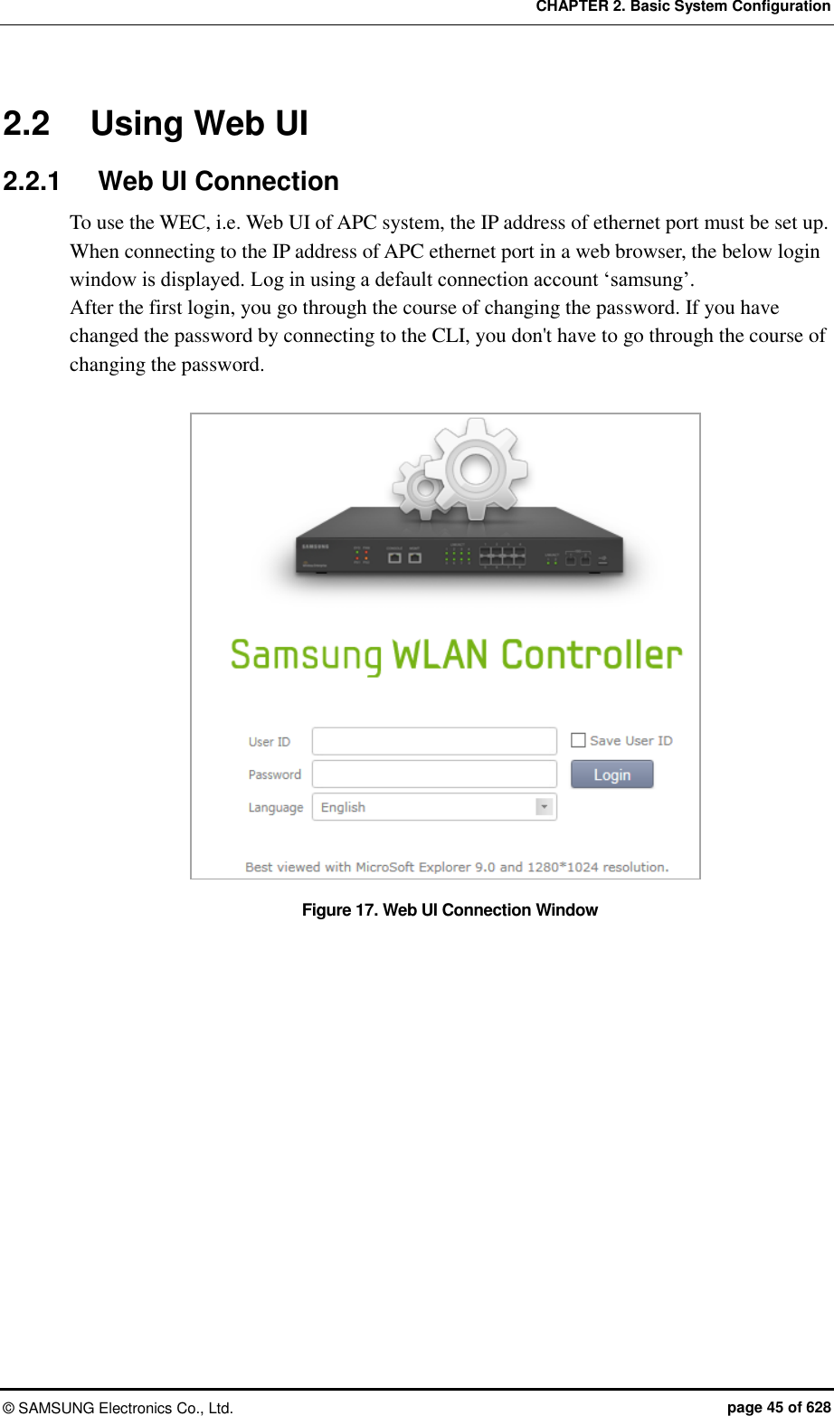
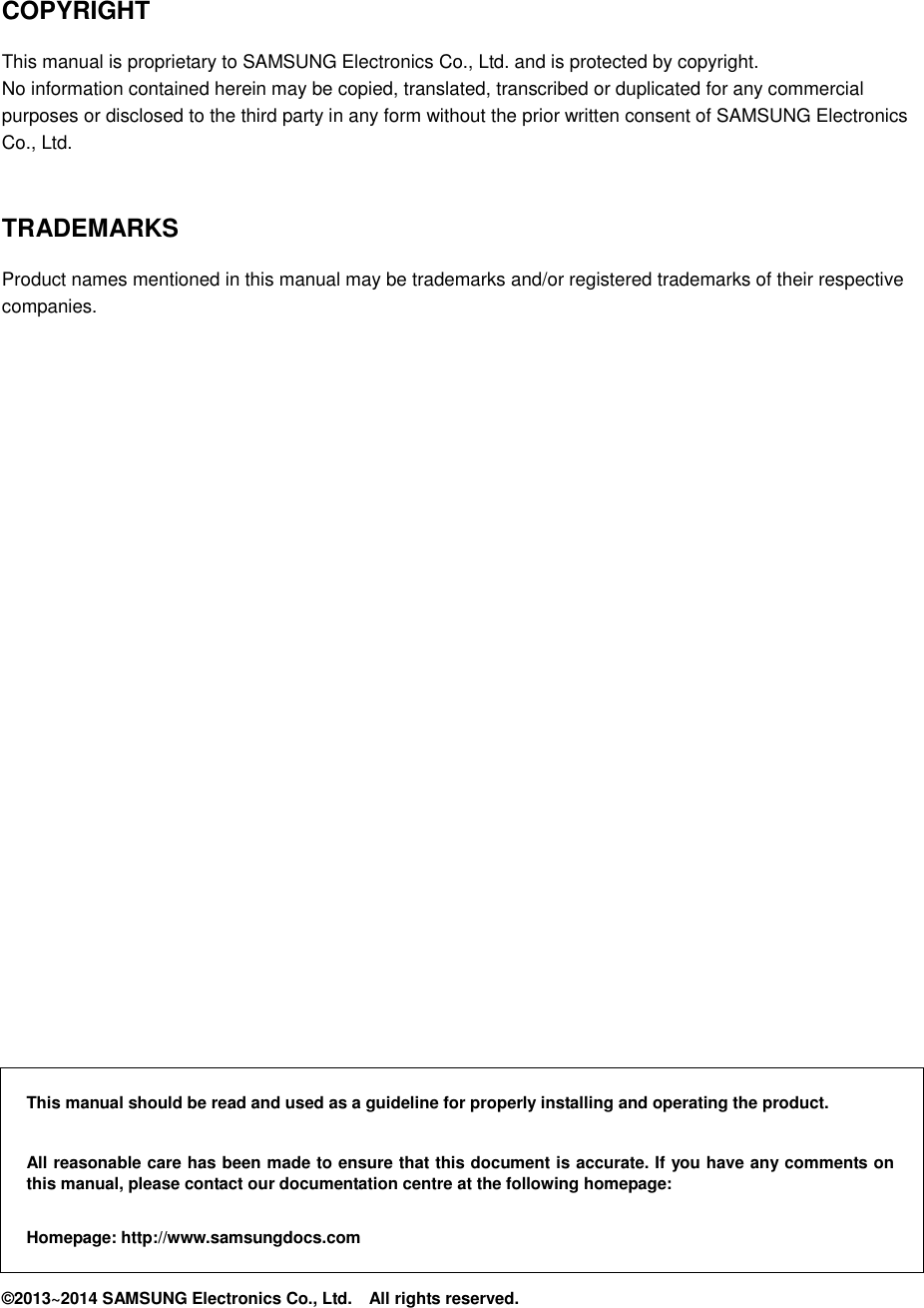
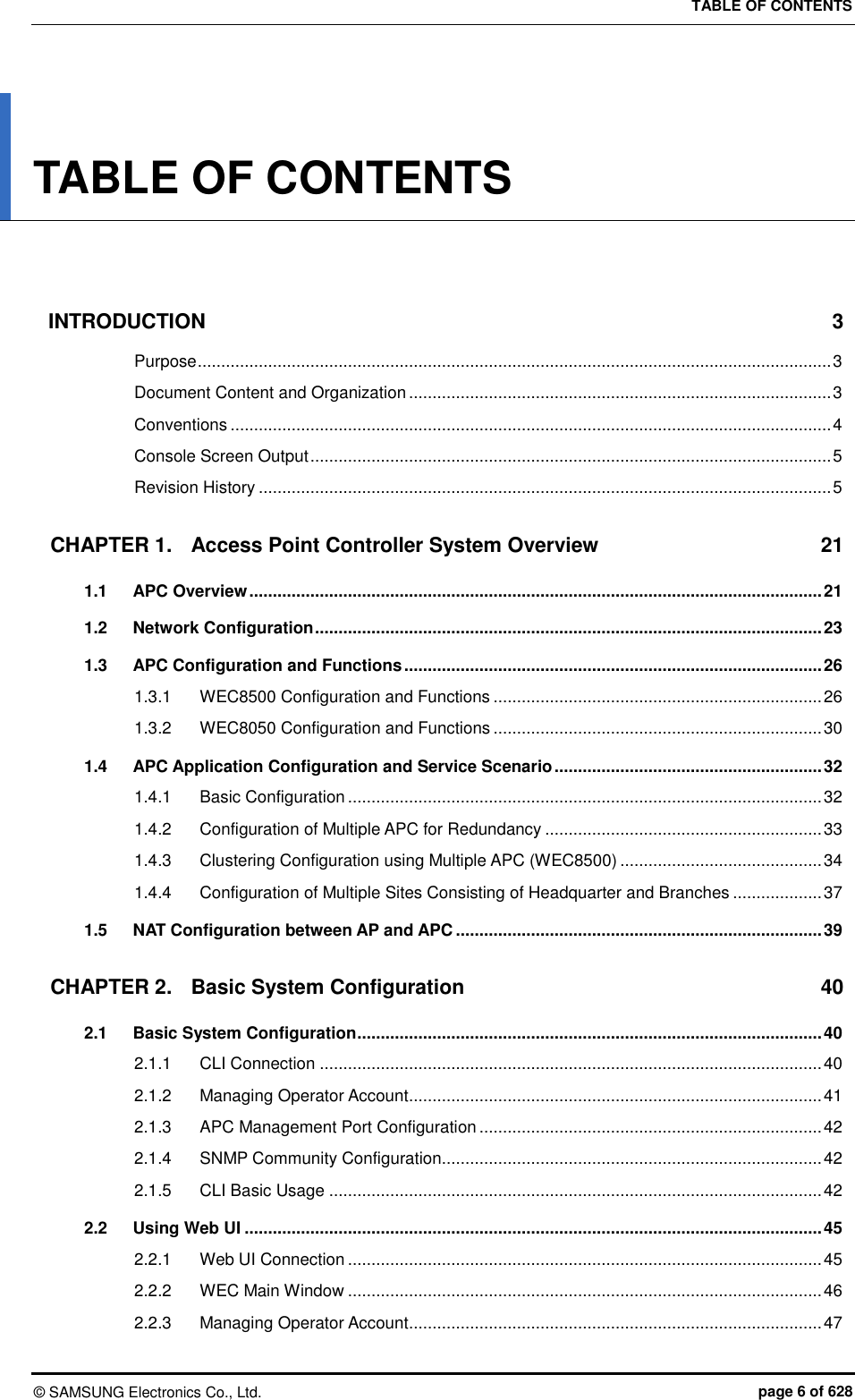
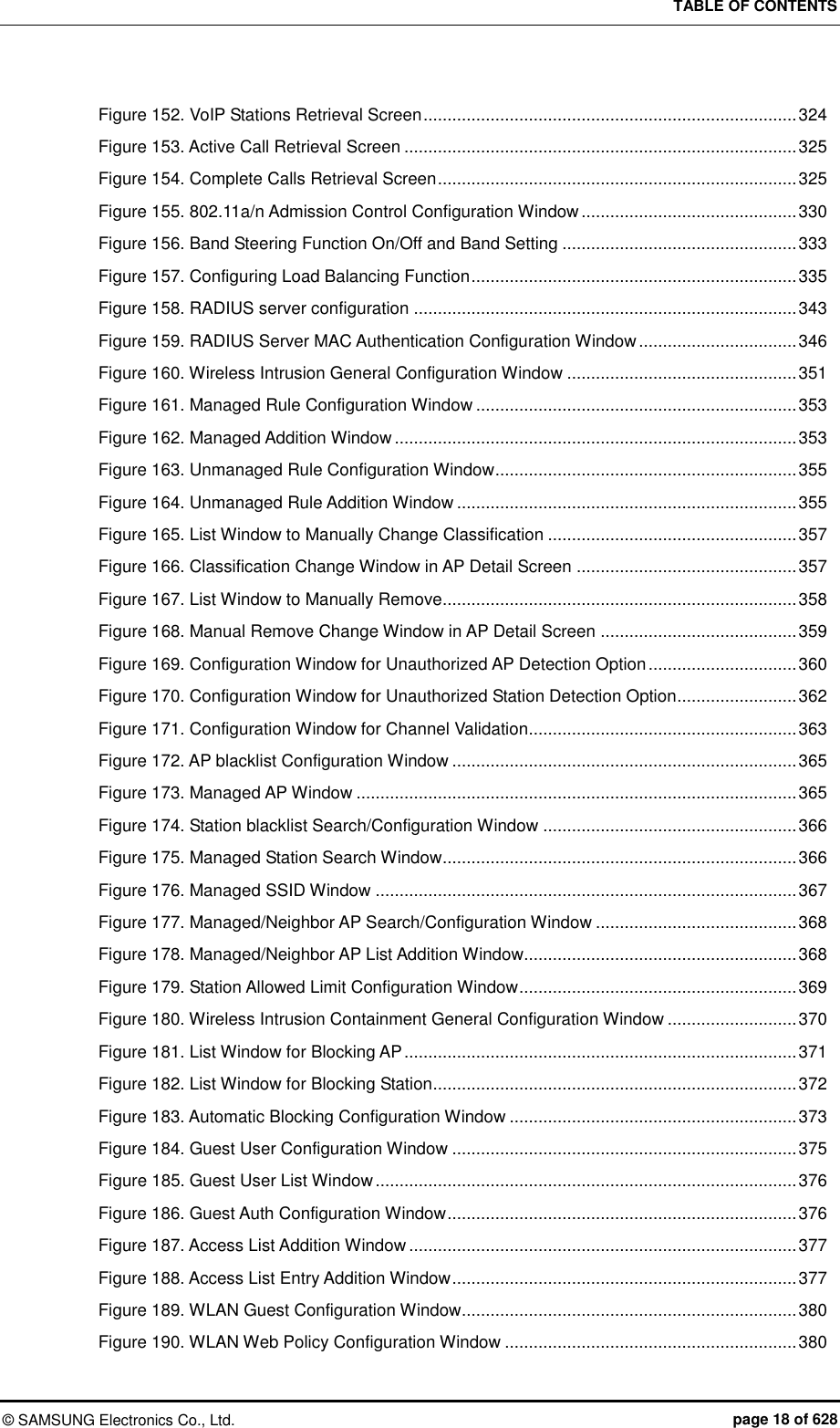
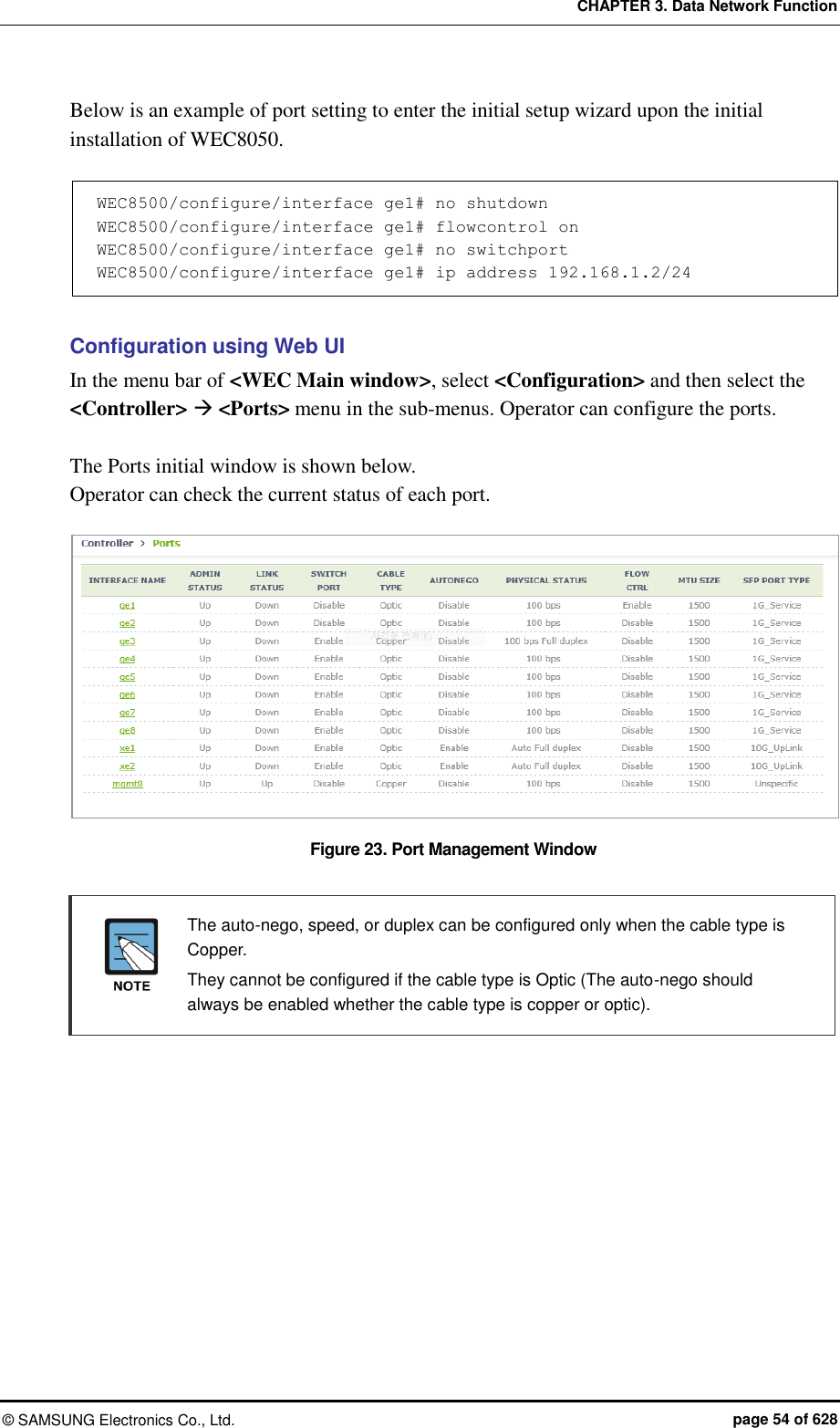
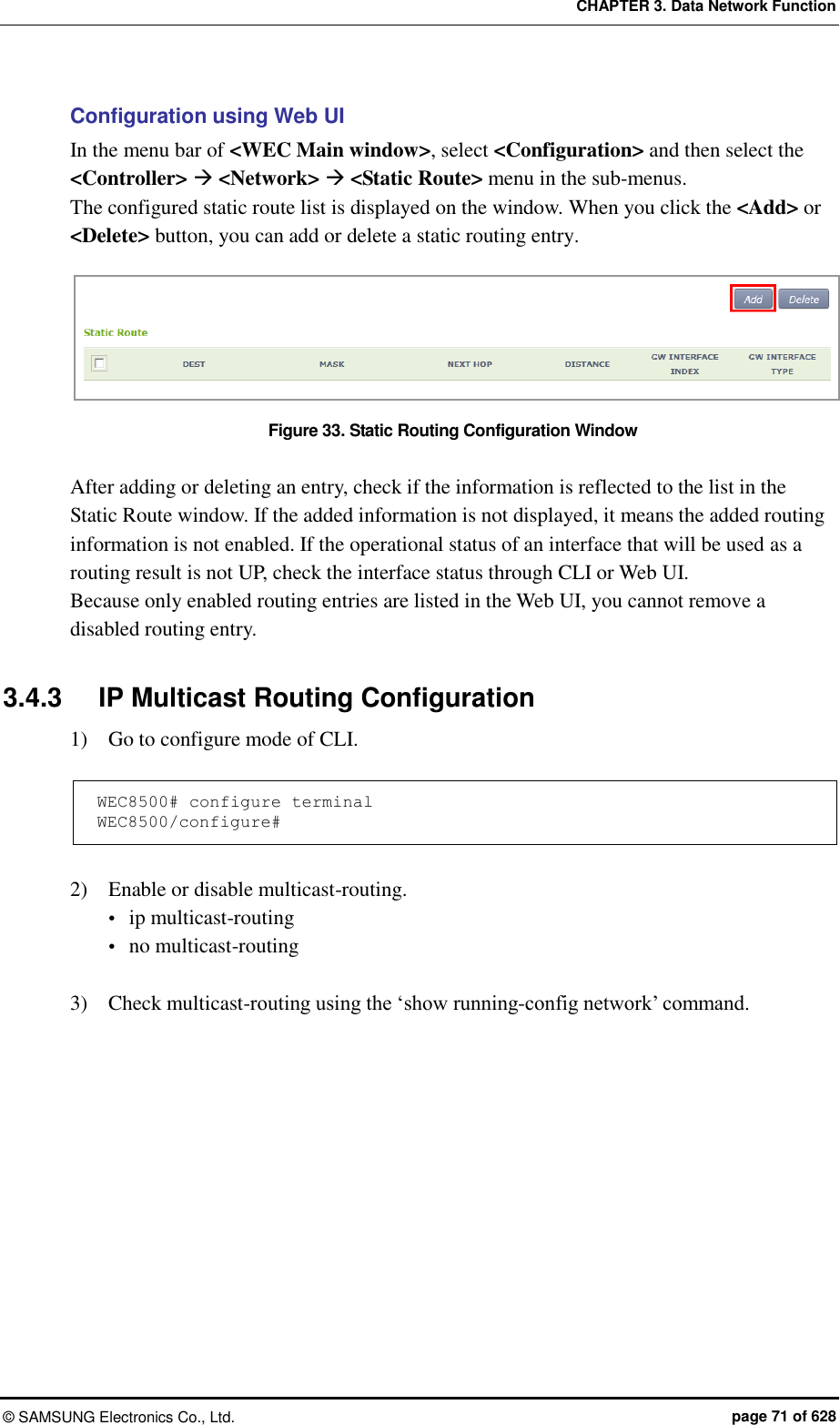
![CHAPTER 3. Data Network Function © SAMSUNG Electronics Co., Ltd. page 52 of 628 CHAPTER 3. Data Network Function In this chapter, how to set up the data network functions of APC including VLAN, link aggregation, and layer 3 protocol is described. 3.1 Port Configuration The APC port is configured with a physical interface. Physical interface of 11 ports except WEC8500 console port Physical interface of 4 ports except WEC8050 console port 3.1.1 Port management The WEC8500 Management port is used to manage the WEC8500. It does not support VLAN and its interface name is ‘mgmt0’. The 8 ports at the right side of Management port are 10/100/1000 BASE T-ports and their names are GE1-8. To the right side of the 10/100/1000 BASE T-ports, there are two Gigabit ports, i.e. XE1 and XE2. In case of WEC8050, there is no management (mgmt0) port. After establishing the IP address in one of ports ge1 to ge4 by using the CLI first, connect the Ethernet cable to the port. Configuration using CLI To configure the port related function, enter into the interface mode by entering the ‘interface [INTERFACE_NAME]’ command in the configure mode. An example of entering into the interface setup mode of the management port is shown below. WEC8500# configure terminal WEC8500/configure# interface mgmt0 WEC8500/configure/interface mgmt0#](https://usermanual.wiki/Samsung-Electronics-Co/WEA463E.Part-1/User-Guide-2696662-Page-52.png)
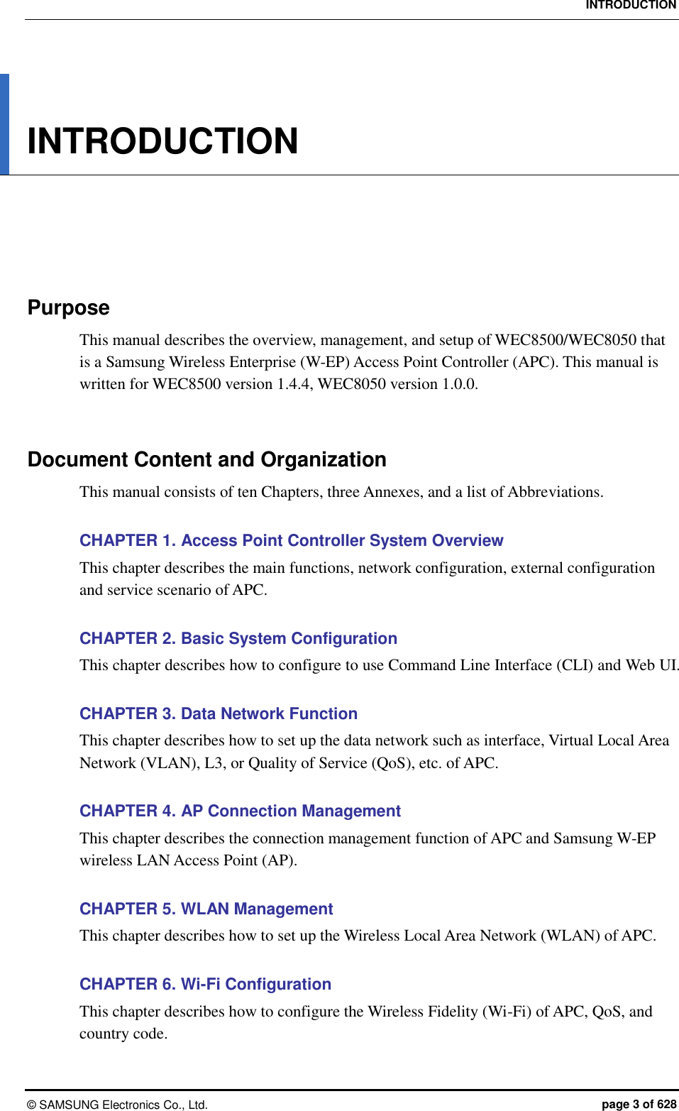
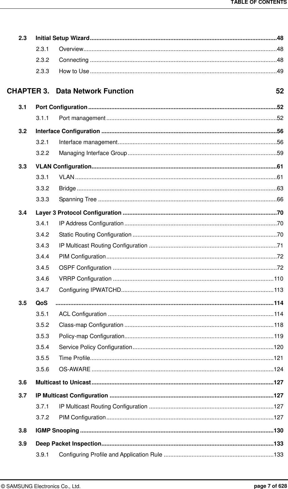
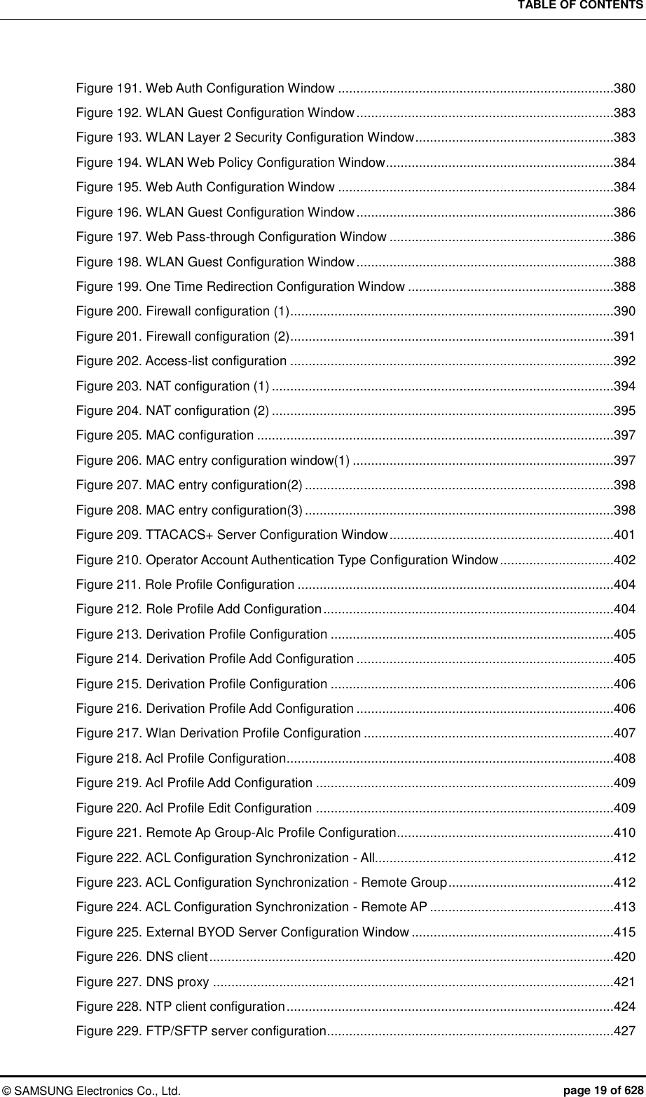
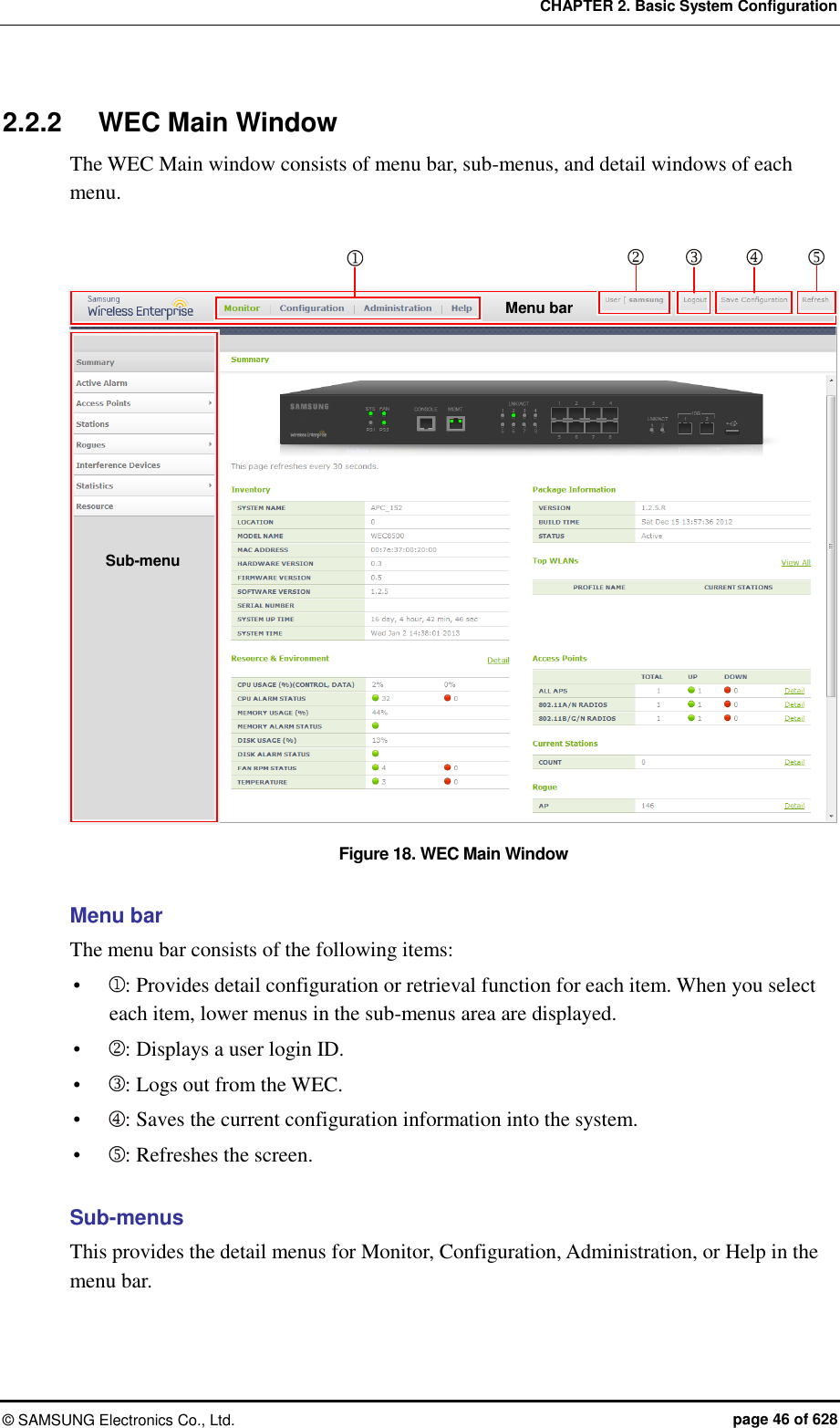
![CHAPTER 3. Data Network Function © SAMSUNG Electronics Co., Ltd. page 53 of 628 The port related CLI commands are as follows: [auto-nego, speed, duplex] The commands used to configure an auto-nego, speed, and duplex addresses are shown below. To delete the configuration, enter the ‘no’ parameter. WEC8500/configure/interface ge1# speed-duplex ? 10-full Set 10Mb/s full-duplex 10-half Set 10Mb/s half-duplex 100-full Set 100Mb/s full-duplex 100-half Set 100Mb/s half-duplex 1000-full Set 1000Mb/s full-duplex 1000-half Set 1000Mb/s half-duplex auto-nego Set auto negotiation speed/duplex [admin status] This is a command that makes the port not working. The ‘no’ parameter is used to restart the port. shutduown no shutdown [flow control] This is a command that operates flow control to the port. The ‘no’ parameter is used to stop the flow control. flowcontrol on no flowcontrol on [switch port] This is a command that changes the port to the L2 mode. The ‘no’ parameter is used to change it to the L3 mode. switchport no switchport [ip address] This is a command that configures a static IP address. To delete the configuration, enter the ‘no’ parameter. ip address {A.B.C.D/mask length} no ip address {A.B.C.D} {A.B.C.D} no ip address {A.B.C.D/mask length}](https://usermanual.wiki/Samsung-Electronics-Co/WEA463E.Part-1/User-Guide-2696662-Page-53.png)
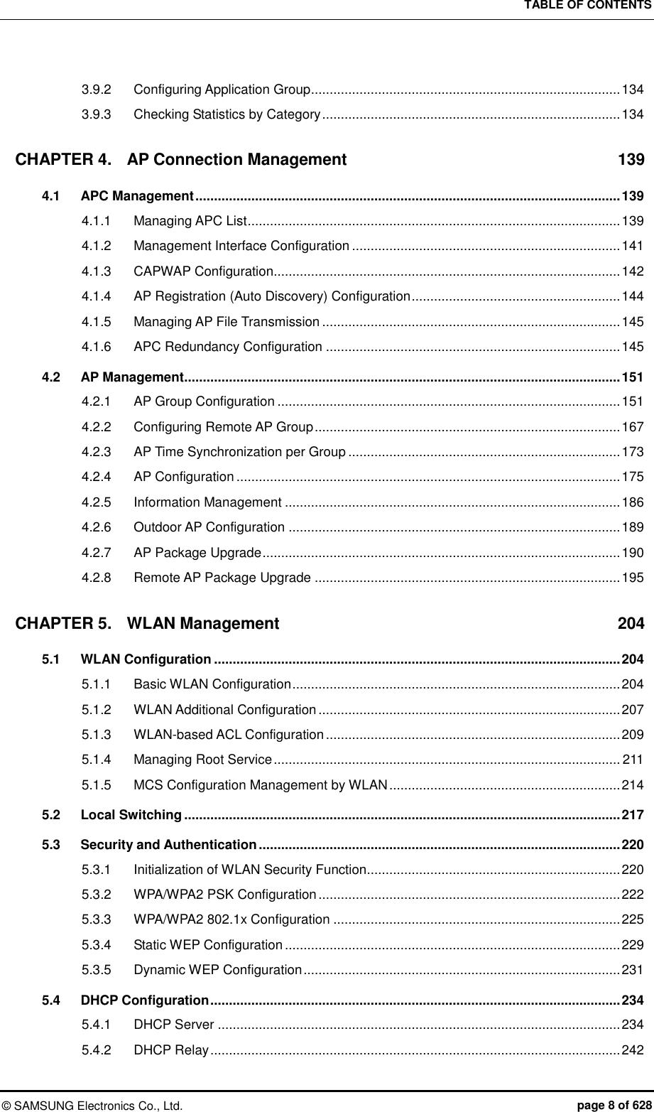
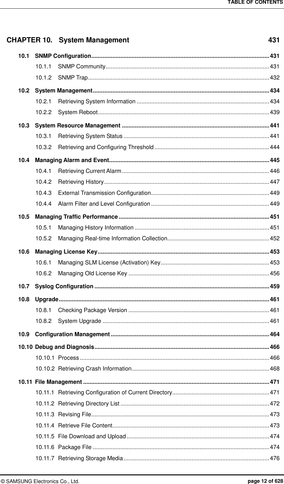
![CHAPTER 3. Data Network Function © SAMSUNG Electronics Co., Ltd. page 55 of 628 [Port Configuration Change] 1) In the Ports initial window, click the <INTERFACE NAME> button to go to port configuration change window. 2) In the port configuration change window, the auto-nego, speed, duplex, admin status, flow control, mtu size, switch port, or ip address, etc. can be configured. Figure 24. Port Configuration Change Window](https://usermanual.wiki/Samsung-Electronics-Co/WEA463E.Part-1/User-Guide-2696662-Page-55.png)
![CHAPTER 3. Data Network Function © SAMSUNG Electronics Co., Ltd. page 56 of 628 3.2 Interface Configuration The WEC8500 interface consists of the following physical interface and virtual interface. Physical interface of 11 ports except console port 1024 virtual interfaces using VLAN There are two types of WEC8050 interface as shown below; physical interface and virtual interface. Physical interface of 4 ports except console port 128 virtual interfaces using VLAN 3.2.1 Interface management The WEC8500 Management port is used to manage the WEC8500. It does not support VLAN and its interface name is ‘mgmt0’. The 8 ports at the right side of Management port are 10/100/1000 BASE T-ports and their names are GE1-8. To the right side of the 10/100/1000 BASE T-ports, there are two Gigabit ports, i.e. XE1 and XE2. Configuration using CLI To configure the interface related function, go to the interface mode by entering the ‘interface [INTERFACE_NAME]’ command in the configure mode. An example of entering into the interface mode of the management port is shown below. WEC8500# configure terminal WEC8500/configure# interface mgmt0 WEC8500/configure/interface mgmt0# The interface related CLI commands are as follows: [ip address] This is a command that configures a static IP address. The ‘no’ parameter is used to delete the configuration. ip address {A.B.C.D/mask length} no ip address {A.B.C.D} {A.B.C.D} no ip address {A.B.C.D/mask length}](https://usermanual.wiki/Samsung-Electronics-Co/WEA463E.Part-1/User-Guide-2696662-Page-56.png)
![CHAPTER 3. Data Network Function © SAMSUNG Electronics Co., Ltd. page 57 of 628 [ip address dhcp] This is a command that configures a dynamic IP address using DHCP. The ‘no’ parameter is used to delete the configuration. ip address dhcp no ip address dhcp [shutdown] This is a command that makes the interface not working. The ‘no’ parameter is used to restart the interface. shutdown no shutdown Configuration using Web UI In the menu bar of <WEC Main window>, select <Configuration> and then select the <Controller> <Interfaces> menu in the sub-menus. You can configure an interface and VLAN. The Interface initial window is shown below. Figure 25. Interfaces Window (1) [Adding VLAN] 1) In the Interface initial window, click the <Add> button to go to VLAN creation window. 2) Enter an INTERFACE NAME and VLAN ID in the VLAN creation window. The INTERFACE NAME describes a VLAN to create and English characters without a space, numbers, and ‘_’ can be used. The VLAN ID is the number from 1 to 4094 and it specifies a unique VLAN value. Click the <Apply> button to go to detail configuration screen. Figure 26. Interfaces Window (2)](https://usermanual.wiki/Samsung-Electronics-Co/WEA463E.Part-1/User-Guide-2696662-Page-57.png)
![CHAPTER 3. Data Network Function © SAMSUNG Electronics Co., Ltd. page 58 of 628 3) Perform detail configuration in the VLAN detail configuration window. If you specify PRIMARY DHCP SERVER or SECONDARY DHCP SERVER in the DHCP area, you can specify the configuration of a DHCP server. After configuration, click the <Apply> button to apply it to the system. Figure 27. Interfaces Window (3) [Deleting VLAN] In the Interface initial window, click the <Delete> button to delete a selected VLAN. The select VLAN cannot be deleted if it is being used in the system.](https://usermanual.wiki/Samsung-Electronics-Co/WEA463E.Part-1/User-Guide-2696662-Page-58.png)
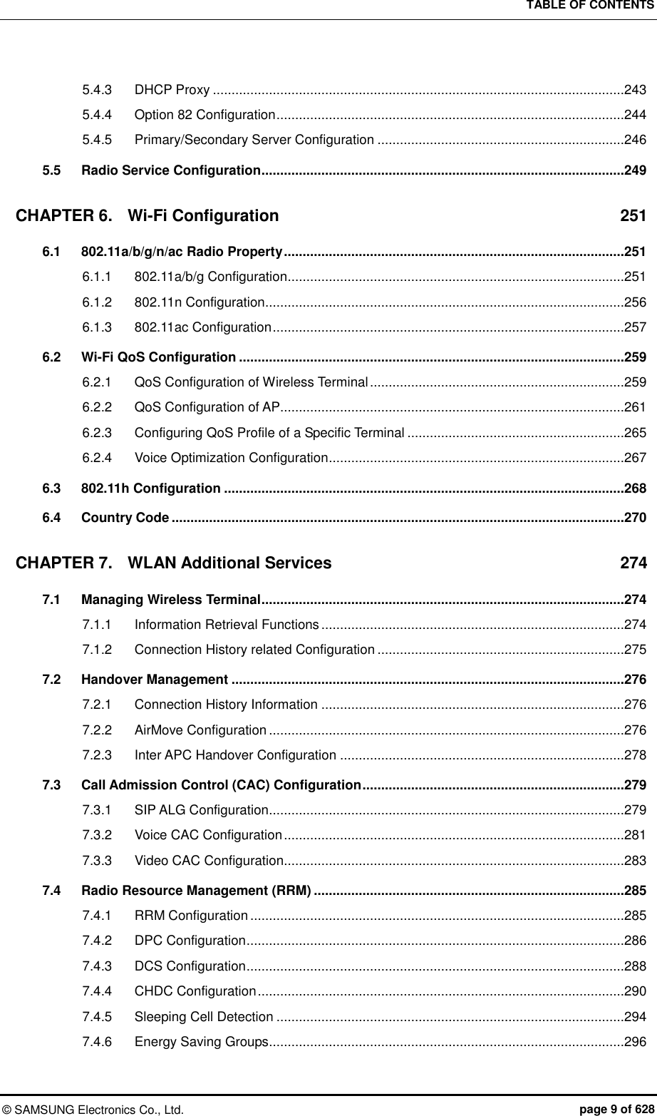
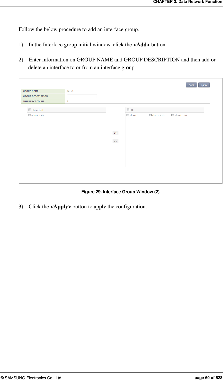
![CHAPTER 3. Data Network Function © SAMSUNG Electronics Co., Ltd. page 59 of 628 3.2.2 Managing Interface Group To use WLAN and other services, it is necessary to configure an interface into an interface group. Configuration using CLI An example of entering into the group configuration mode of ifg_01 interface is shown below. WEC8500# configure terminal WEC8500/configure# if-group ifg_01 Interface Group related commands are as follows: [Creating or Deleting Interface group] This command creates an interface group. Use ‘no’ parameter to delete an interface group. if-group [INTERFACE_GROUP_NAME] no if-group [INTERFACE_GROUP_NAME] [Adding or deleting Interface] This command adds an interface to an interface group being configured. Use ‘no’ parameter to delete an interface. add-if[INTERFACE_IP_ADDRESS] no add-if[INTERFACE_ IP_ADDRESS] [Retrieving Interface Group Status] This command retrieves the configuration status of an interface group. show if-group Configuration using Web UI In the menu bar of <WEC Main window>, select <Configuration> and then select the <Controller> <Interfaces Groups> menu in the sub-menus. Click the <Add> or <Delete> button to add or delete an interface group. Figure 28. Interface Group Window (1)](https://usermanual.wiki/Samsung-Electronics-Co/WEA463E.Part-1/User-Guide-2696662-Page-59.png)
![CHAPTER 3. Data Network Function © SAMSUNG Electronics Co., Ltd. page 61 of 628 3.3 VLAN Configuration 3.3.1 VLAN Configuration using CLI To configure VLAN, go to the VLAN interface mode by executing the following command. WEC8500# configure terminal WEC8500/configure# interface vlan WEC8500/configure/interface vlan# The related command is shown below and the range of VLAN ID is 1-4094. [vlan bridge] This command creates VLAN. The ‘no’ parameter is used to delete VLAN. vlan [VLAN_ID] bridge 1 no vlan [VLAN_ID] bridge 1 [switchport access vlan] This command set the VLAN mode to the access or hybrid mode. The ‘no’ parameter is used to delete the VLAN configuration. switchport {access/hybrid} vlan [VLAN_ID] [switchport mode] This command configures the mode of switch port. The ‘no’ parameter is used to delete the configuration. switchport mode {access/hybrid/trunk} no switchport mode [switchport hybrid allowed vlan] This command configures the mode of switch port to hybrid. The ‘no’ parameter is used to delete the configuration. switchport hybrid allowed vlan: Configures VLAN to hybrid. switchport hybrid allowed vlan all: Configures all the allowed VLANs to hybrid. switchport hybrid allowed vlan none: Stops VLAN data transmission/reception. switchport hybrid allowed vlan add [VLAN_ID]: Adds VLAN to the hybrid mode. switchport hybrid allowed vlan remove [VLAN_ID]: Deletes VLAN from the hybrid mode. no switchport hybrid vlan: Deletes all the hybrid settings.](https://usermanual.wiki/Samsung-Electronics-Co/WEA463E.Part-1/User-Guide-2696662-Page-61.png)
![CHAPTER 3. Data Network Function © SAMSUNG Electronics Co., Ltd. page 62 of 628 [switchport trunk allowed vlan] This command configures the mode of switch port to trunk. The ‘no’ parameter is used to delete the configuration. switchport trunk allowed vlan: Configure VLAN to the trunk mode. switchport trunk allowed vlan all: Configure all the VLANs to the trunk mode. switchport trunk allowed vlan none: Stops VLAN data transmission/reception. switchport trunk allowed vlan add [VLAN_ID]: Adds VLAN to the trunk mode. switchport trunk allowed vlan remove [VLAN_ID]: Removes VLAN with the trunk mode. no switchport trunk vlan: Removes all the trunk settings. [show vlan] This command retrieves VLAN configuration status. show vlan [VLAN_ID]: Displays specific VLAN information. show vlan all bridge 1: Displays all the VLAN information. show vlan brief: Displays all the VLAN information briefly. show vlan dynamic bridge 1: Displays dynamic VLAN information. show vlan static bridge 1: Displays static VLAN information. [Typical configuration procedure] The typical configuration procedure of VLAN is as follows: WEC8500# configure terminal WEC8500/configure# bridge 1 protocol mstp WEC8500/configure # vlan database WEC8500/configure/vlan#vlan {2-4094} bridge 1 WEC8500/configure/vlan# exit WEC8500/configure# interface vlan1.{2-4094} Configuration using Web UI In the menu bar of <WEC Main window>, select <Configuration> and then select the <Controller> <Interfaces> menu in the sub-menus. For more information about configuration procedure, see ‘3.2.1 Interface Management’.](https://usermanual.wiki/Samsung-Electronics-Co/WEA463E.Part-1/User-Guide-2696662-Page-62.png)
![CHAPTER 3. Data Network Function © SAMSUNG Electronics Co., Ltd. page 63 of 628 3.3.2 Bridge To set up bridge related functions, go to configure mode by executing the following command WEC8500# configure terminal The bridge related commands are as follows: [bridge address] This command configures a bridge address. The ‘no’ parameter is used to clear the configuration. bridge 1 address [MAC] [forward/discard] [IFNAME] no bridge 1 address [MAC] [forward/discard] [IFNAME] Parameter Description MAC MAC address. Entered in the format of HHHH.HHHH.HHHH. forward/discard - forward: Configures forward matching frame. - discard: Configures discard matching frame. IFNAME Interface name of a bridge. [bridge ageing time] This command configures the age-out time of a bridge. The ‘no’ parameter is used to clear the configuration. bridge-group 1 ageing-time [AGEINGTIME] no bridge-group 1 ageing-time Parameter Description AGEINGTIME age-out time (range: 10-1000000 s) [bridge protocol] This command creates a bridge in one of the IEEE 802.1Q Spanning-Tree Protocol (STP), IEEE802.1s multiple STP (MSTP), or IEEE 802.1W Rapid STP (RSTP) protocol. bridge 1 protocol [PROTOCOL] no bridge 1 protocol Parameter Description PROTOCOL Protocol to configure (ieee/mstp/rstp) - ieee: STP - mstp: MSTP](https://usermanual.wiki/Samsung-Electronics-Co/WEA463E.Part-1/User-Guide-2696662-Page-63.png)
![CHAPTER 3. Data Network Function © SAMSUNG Electronics Co., Ltd. page 64 of 628 Parameter Description - rstp: RSTP [clear mac address-table] This command deletes the filtering database of a default bridge. clear mac address-table [OPTION] [KIND] [WORD] Parameter Description OPTION Filtering database option (static/multicast) - static: Filtering database item that is configured as static - multicast: Filtering database item that is automatically configured by the multicast protocol KIND Filtering database type (address/vlan/interface) - address: Filtering database using a MAC address - vlan: Filtering database using the VLAN information. - interface: Filtering database using the interface information WORD Option [clear mac address-table dynamic] This command deletes bridge operation among the filtering database of a default bridge. clear mac address-table dynamic [KIND] [WORD] Parameter Description KIND Filtering database type (address/vlan/interface) - address: Filtering database using a MAC address - vlan: Filtering database using the VLAN information. - interface: Filtering database using the interface information WORD Option [clear mac address-table dynamic bridge] This command deletes the filtering database of bridge operation. clear mac address-table dynamic bridge [BRIDGE_NAME] clear mac address-table dynamic [address/interface/vlan] [WORD] bridge [NAME] Parameter Description KIND Filtering database type (address/vlan/interface) - address: Filtering database using a MAC address - vlan: Filtering database using the VLAN information. - interface: Filtering database using the interface information WORD Option BRIDGE_NAME Bridge name](https://usermanual.wiki/Samsung-Electronics-Co/WEA463E.Part-1/User-Guide-2696662-Page-64.png)
![CHAPTER 3. Data Network Function © SAMSUNG Electronics Co., Ltd. page 65 of 628 [show bridge] This command retrieves bridge information. show bridge [show interface switchport bridge] This command retrieves the bridge information, i.e. the layer 2 protocol characteristic information of the current VLAN, of a switch port. show interface switchport bridge [BRIDGE_NAME] Parameter Description BRIDGE_NAME Bridge name [switchport] This command configures a switch port, i.e. the layer 2 protocol characteristic information of the current VLAN. The ‘no’ parameter is used for default configuration. Go to interface mode and then execute the command. switchport no switchport](https://usermanual.wiki/Samsung-Electronics-Co/WEA463E.Part-1/User-Guide-2696662-Page-65.png)
![CHAPTER 3. Data Network Function © SAMSUNG Electronics Co., Ltd. page 66 of 628 3.3.3 Spanning Tree Configuration using CLI To set up spanning tree related functions, go to configure mode by executing the following command. WEC8500# configure terminal The related command is as follows. [bridge forward-time] This command configures the forward time of a bridge. The ‘no’ parameter is used for default configuration. bridge 1 forward-time [FORWARD_DELAY] no bridge 1 forward-time Parameter Description FORWARD_DELAY Forward time delay (range: 4-30 s, default: 15) [bridge hello-time] This command configures the hello time of a bridge. The time required when a bridged LAN is changed to Bridge Protocol Data Units (BPDUs) is called as hello-time. The ‘no’ parameter is used for default configuration. bridge 1 hello-time [HELLOTIME] no bridge 1 hello-time Parameter Description HELLOTIME Hello BPDU interval (range: 1-10 s) [bridge instance priority] This command configures the bridge priority of MST instance. The ‘no’ parameter is used to delete priority. bridge 1 instance [INSTANCE_ID] priority [BRIDGE_PRIORITY] no bridge 1 instance [INSTANCE_ID] Parameter Description INSTANCE_ID Instance ID (range: 1-64) BRIDGE_PRIORITY Bridge priority (range: 0-61440)](https://usermanual.wiki/Samsung-Electronics-Co/WEA463E.Part-1/User-Guide-2696662-Page-66.png)
![CHAPTER 3. Data Network Function © SAMSUNG Electronics Co., Ltd. page 67 of 628 [bridge max-age] This command configures the max-age of a bridge. The ‘no’ parameter is used for default configuration. bridge 1 max-age [MAXAGE] no bridge 1 max-age Parameter Description MAXAGE Configures a maximum time (range: 6-40 s) [bridge max-hops] This command configures the maximum allowed number of hops of a Bridge Protocol Data Unit (BPDU) bridge in the MST area. The ‘no’ parameter is used for default configuration. bridge 1 max-hops [HOP_COUNT] no bridge 1 max-hops Parameter Description HOP_COUNT Maximum allowed number of hops [bridge multiple-spanning-tree enable] This command configures a MSTP bridge. The ‘no’ parameter is used to clear the configuration. bridge 1 multiple-spanning-tree enable no bridge 1 multiple-spanning-tree enable [bridge rapid-spanning-tree enable] This command configures a RSTP bridge. The ‘no’ parameter is used to clear the configuration. bridge 1 rapid-spanning-tree enable no bridge 1 rapid-spanning-tree enable(bridge-forward) [bridge spanning-tree enable] This command configures a STP bridge. The ‘no’ parameter is used to clear the configuration. bridge 1 spanning-tree enable no bridge 1 spanning-tree enable(bridge-forward)](https://usermanual.wiki/Samsung-Electronics-Co/WEA463E.Part-1/User-Guide-2696662-Page-67.png)
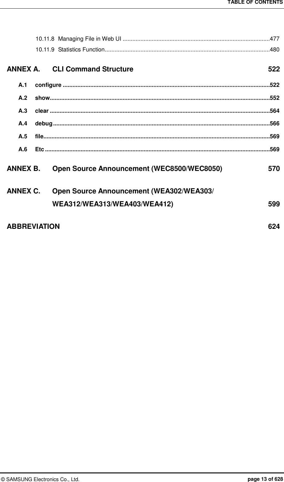
![CHAPTER 3. Data Network Function © SAMSUNG Electronics Co., Ltd. page 68 of 628 [bridge priority] This command configures the priority of a bridge. The ‘no’ parameter is used to delete a priority. bridge 1 priority [PRIORITY] no bridge 1 priority Parameter Description PRIORITY Bridge priority (range: 0-61440) [bridge shutdown] This command clears bridge settings. The ‘no’ parameter is used to restart a bridge. bridge shutdown [1-32] no bridge shutdown [1-32] Configuration using Web UI In the menu bar of <WEC Main window>, select <Configuration> and then select the <Controller> <Network> <MSTP> menu in the sub-menus. The sub-menus of the MSTP menu are as follows: Config: Configures the spanning tree. Instance: Manages the MSTP VLAN instance. Port: Manages the MSTP port. [Configuring Spanning Tree] After selecting the <Config> menu, enter configuration information and then click the <Apply> button. Figure 30. Spanning Tree Configuration Window (1)](https://usermanual.wiki/Samsung-Electronics-Co/WEA463E.Part-1/User-Guide-2696662-Page-68.png)
![CHAPTER 3. Data Network Function © SAMSUNG Electronics Co., Ltd. page 69 of 628 [Managing the MSTP VLAN instance] When you select the <Instance> menu, the configured MSTP VLAN Instance list is displayed on the window. Click the <Add> or <Delete> button to add or delete an instance. Figure 31. Spanning Tree Configuration Window (2) [Managing MSTP Port] When you select the <Port> menu, the configured MSTP Port list is displayed on the window. Click the <Add> or <Delete> button to add or delete a port. Figure 32. Spanning Tree Configuration Window (3)](https://usermanual.wiki/Samsung-Electronics-Co/WEA463E.Part-1/User-Guide-2696662-Page-69.png)
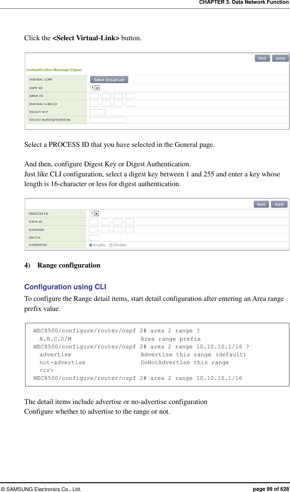
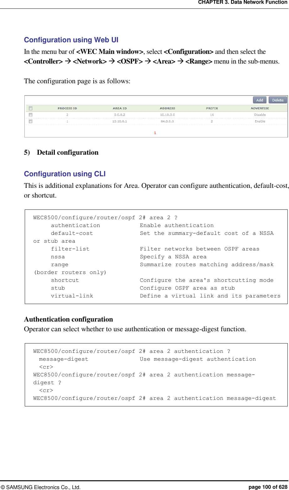
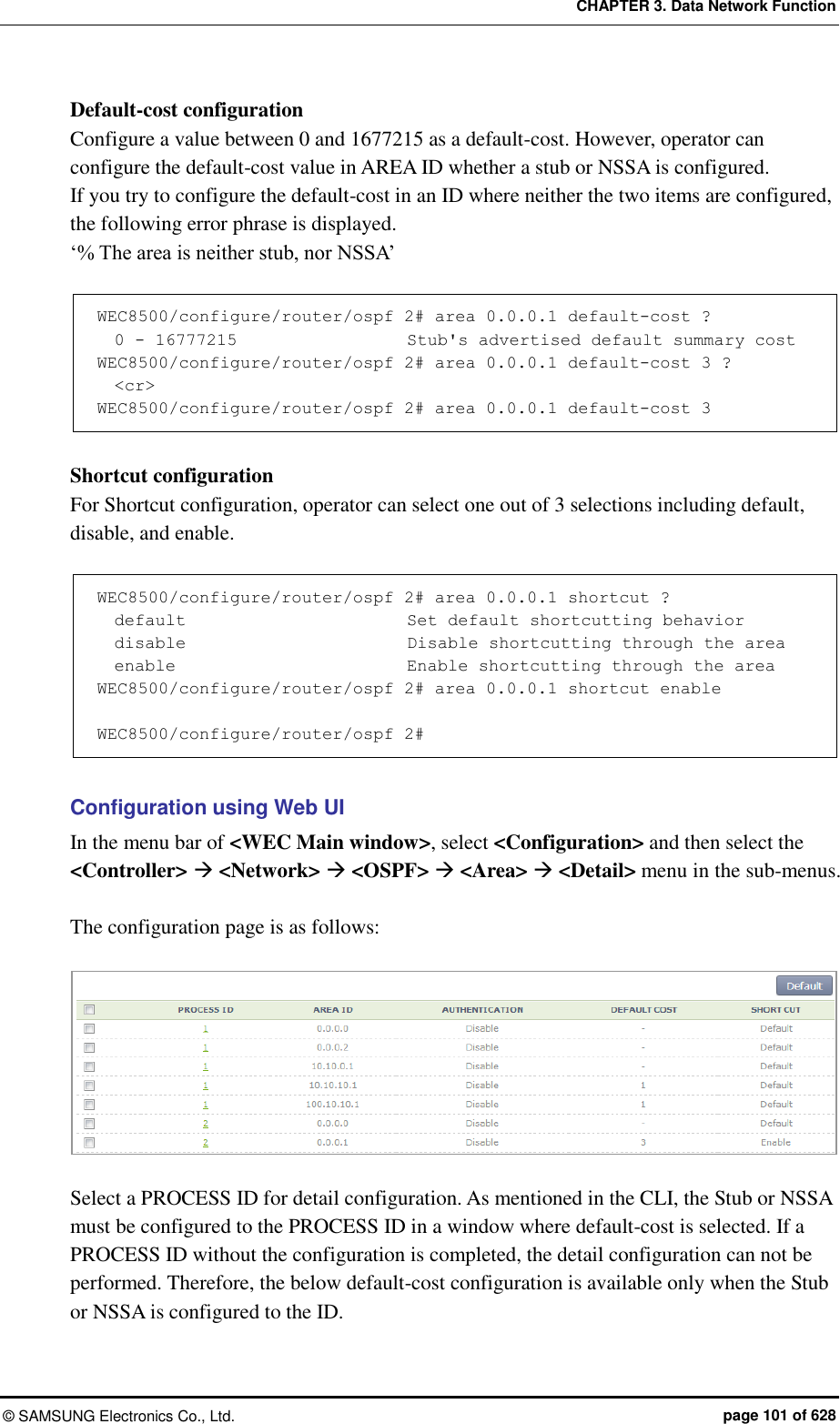
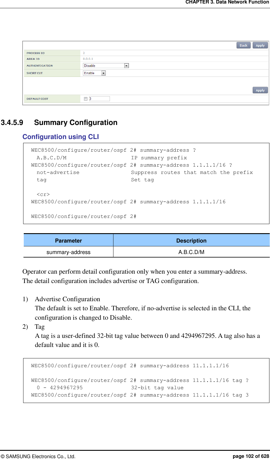
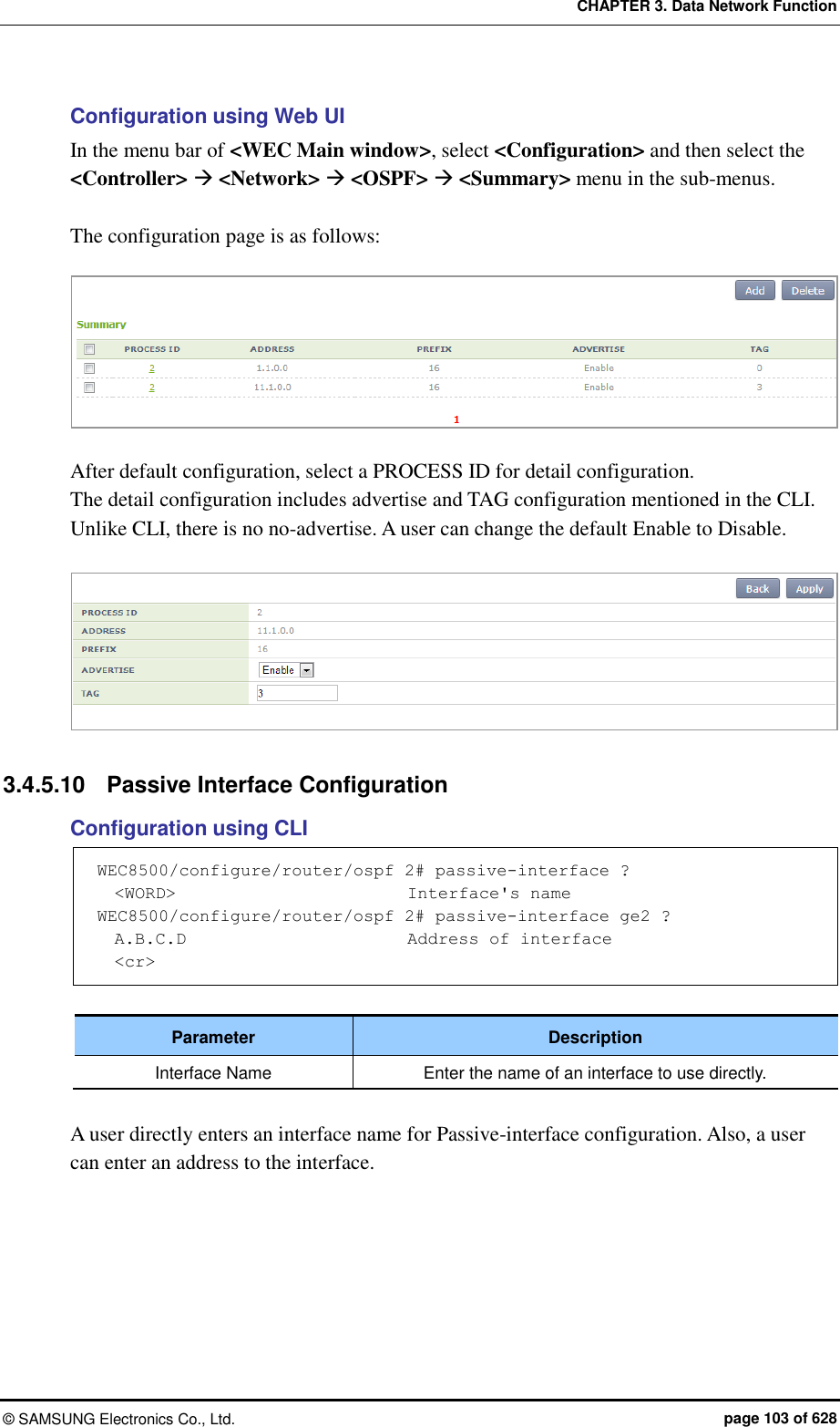
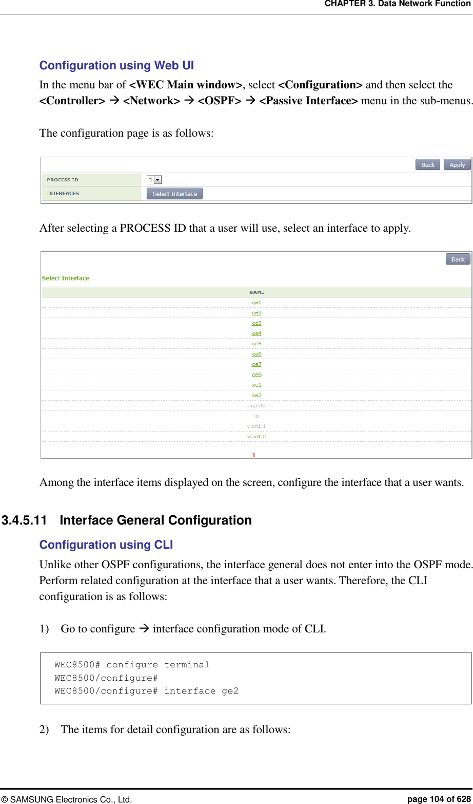
![CHAPTER 3. Data Network Function © SAMSUNG Electronics Co., Ltd. page 110 of 628 3.4.6 VRRP Configuration The Virtual Router Redundancy Protocol (VRRP) is an Internet protocol that provides the backup router operation method in a LAN. If a fault occurs with a router that transmits a packet from a host in a LAN, decide a virtual IP address in a DHCP manually or by default by using a virtual router fault recovery protocol and share it among routers. Once a primary router and a backup router are decided, the backup router becomes a primary router when a fault occurs with the primary router. Configuration using CLI To configure the VRRP related function, go to configure router mode of CLI, enter a router ID and interface name to go to the VRRP configuration mode. WEC8500# configure terminal WEC8500/configure# router WEC8500/configure# router vrrp WEC8500/configure# router vrrp 1 vlan1.10 WEC8500/configure/router/vrrp# The following commands are provided. [advertisement-interval] This command configures the advertisement interval of VRRP in second. A user can configure the interval from 1 to 10. advertisement-interval [INTERVAL] Parameter Description INTERVAL Advertisement interval (range: 1-10 s) [circuit-failover] Enter an interface to configure and its priority. circuit-failover [WORD] [PRIORITY] Parameter Description WORD Interface name PRIORITY Priority setup (range: 1-100) [enable/disable] This command enables or disables the VRRP session. enable disable](https://usermanual.wiki/Samsung-Electronics-Co/WEA463E.Part-1/User-Guide-2696662-Page-110.png)
![CHAPTER 3. Data Network Function © SAMSUNG Electronics Co., Ltd. page 111 of 628 [preempt-delay] This command configures the preempt delay time. preempt-delay [DELAY_TIME] Parameter Description DELAY_TIME Preempt delay time (range: 0-3600 s) [preempt-mode] This command configures whether to use the preempt mode. preempt-mode [MODE] Parameter Description MODE - true: Use the preempt mode - false: Stop using the preempt mode. [priority] This command configures a priority. priority [PRIORITY] Parameter Description PRIORITY Priority setup (range: 1-255) [virtual-ip] This command configures an IP address to use in the VRRP and configure the IP address as master or backup. virtual-ip [A.B.C.D] virtual-ip [A.B.C.D] [MODE] Parameter Description A.B.C.D IP address MODE IP configuration mode (backup/master) - backup: Backup router configuration. - master: Master configuration. [show vrrp] This command retrieves VRRP configuration. show vrrp](https://usermanual.wiki/Samsung-Electronics-Co/WEA463E.Part-1/User-Guide-2696662-Page-111.png)
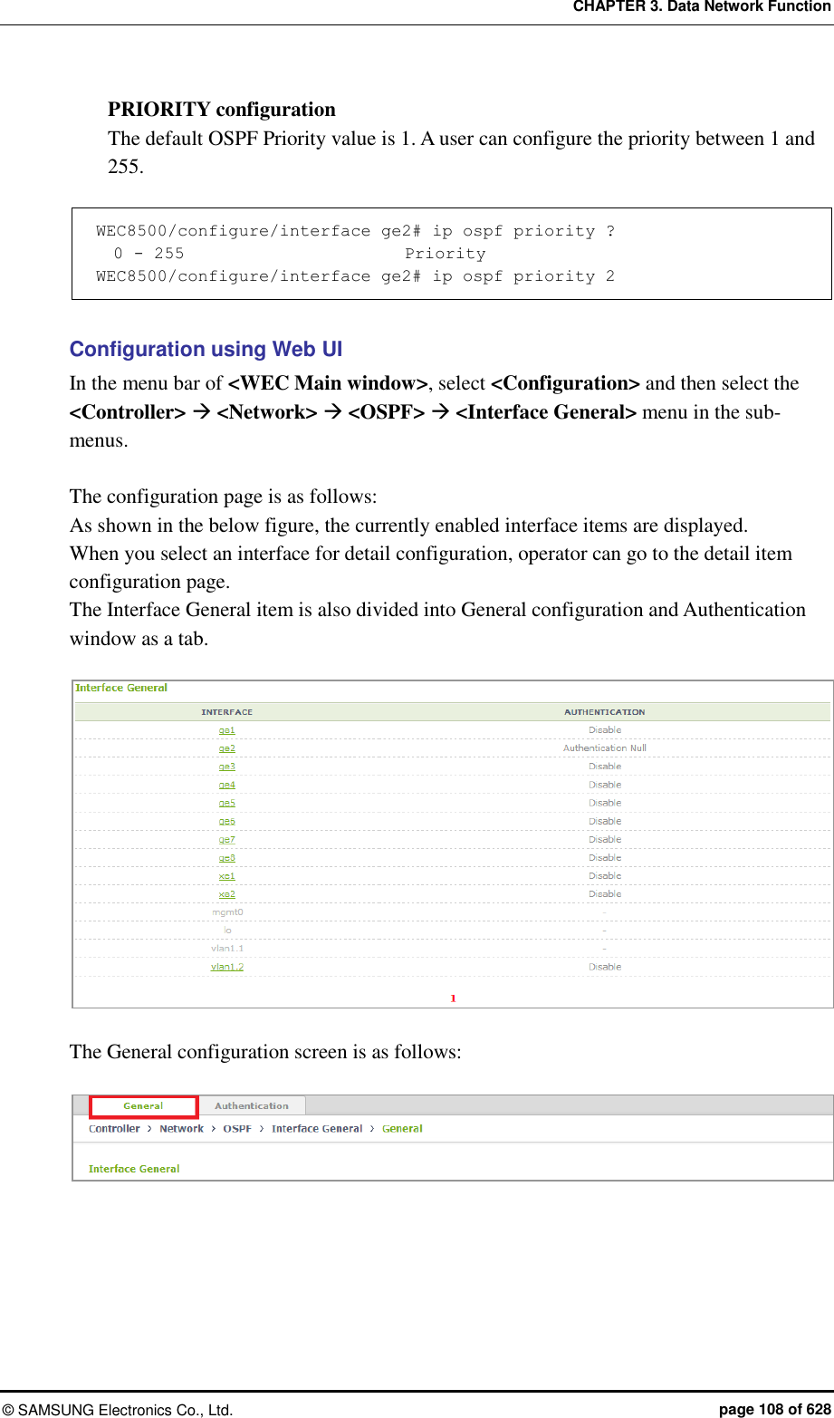
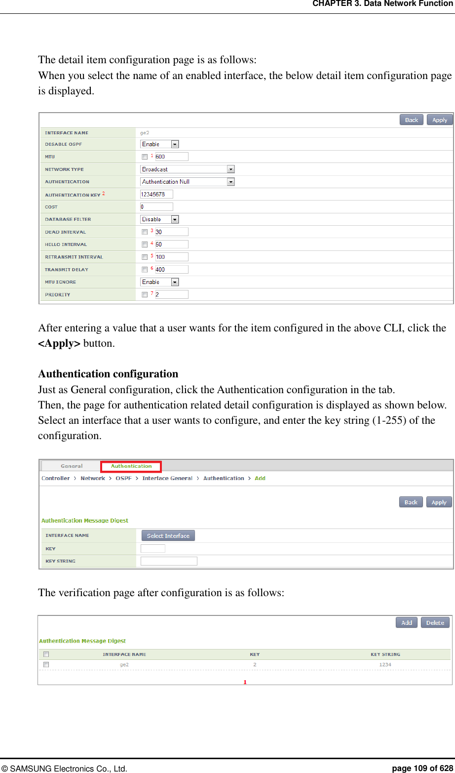
![CHAPTER 3. Data Network Function © SAMSUNG Electronics Co., Ltd. page 112 of 628 Configuration using Web UI In the menu bar of <WEC Main window>, select <Configuration> and then select the <Controller> <Network> <VRRP> menu in the sub-menus. The VRRP menu provides two sub menus, i.e. Operation and Circuit Failover. [Operation] When you click the <Enable>/<Disable> button, you can Enable or disable VRRP. In addition, when you click the <Add> or <Delete> button, you can add or delete VRRP configuration. Figure 35. VRRP-Operation Window [Circuit Failover] When you click the Circuit Failover menu, the VRRP list is displayed on the window. Figure 36. VRRP-Circuit Failover Window (1) To perform detail configuration, select one of VRRP items. After selecting a configuration you want select the <Apply> button to apply the configuration. Figure 37. VRRP-Circuit Failover Window (2)](https://usermanual.wiki/Samsung-Electronics-Co/WEA463E.Part-1/User-Guide-2696662-Page-112.png)
![CHAPTER 3. Data Network Function © SAMSUNG Electronics Co., Ltd. page 114 of 628 3.5 QoS The Access Control List (ACL) allows or blocks a specific network traffic based on an operator’s configuration. The APC provides QoS using ACL. 3.5.1 ACL Configuration 3.5.1.1 Access List Configuration You can create or delete an access list for ACL configuration. To delete an access list, an operator can enter the name of an access list directly or enter a command by copying a value retrieved from the ‘show running-config network’. But, if the access list is being used in the WLAN ACL or Admin ACL, etc., you cannot delete it. Therefore, check if it is being used in the WLAN ACL or Admin ACL first of all. Configuration using CLI 1) Go to fqm mode where you can configure the configure rule of CLI. APC# configure terminal APC/configure# fqm-mode 2) Create an access list by entering the ‘access-list’ command. The ‘no’ parameter is used to delete an access list. access-list [ip/ipv6/mac] [ACL_NAME] [deny/permit/time-profile] seq [seq_NUM] [1/*/ahp/eigrp/esp/gre/icmp/igmp/igrp/ip/nos/ospf/pcp/pim/17/6/ tcp/udp/1-255] [any/A.B.C.D A.B.C.D] eq [eq_VALUE] [any/A.B.C.D A.B.C.D] eq [eq_VALUE] [[[dscp [*|[0-63]]|precedence [*|[0-7])]]]|] An example of entering a command is shown below. Creating Access list ‘acl1’: APC# configure terminal APC/configure# fqm-mode APC/configure# access-list ip acl1 permit seq 1 icmp any any Deleting Access list ‘acl1’: APC# configure terminal APC/configure# fqm-mode APC/configure# no access-list ip acl1 permit seq 1 icmp any any 3) Check a created access list using the ‘show running-config network’ command.](https://usermanual.wiki/Samsung-Electronics-Co/WEA463E.Part-1/User-Guide-2696662-Page-114.png)
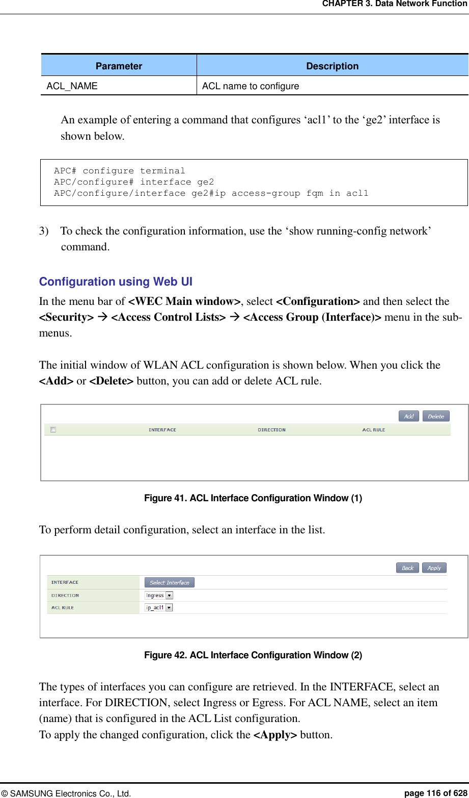
![CHAPTER 3. Data Network Function © SAMSUNG Electronics Co., Ltd. page 115 of 628 Configuration using Web UI In the menu bar of <WEC Main window>, select <Configuration> and then select the <Security> <Access Control Lists> <IP ACL> menu in the sub-menus. The initial window of ACL rule configuration is shown below. When you click the <Add> or <Delete> button, you can add or delete ACL rule. Figure 39. ACL Configuration Window To change the configuration of ACL rule, click ACL NAME to change. You can change the configuration using the <Add> or <Delete> button. In addition, if there is a time profile in an ACL name, the IP ALC window is changed as shown below. After selecting a time profile, click the <Apply> button to apply the time profile to the ACL. Figure 40. Window where a Time Profile is Applied to ACL 3.5.1.2 ACL Rule Configuration Configuration using CLI 1) Go to interface configuration mode where you will apply the configure ACL rule of CLI. APC# configure terminal APC/configure# interface [name] APC/configure/interface [name]# 2) Configure ACL to an interface. ip access-group [MODE] [DIRECTION] [ACL_NAME] Parameter Description MODE Configuration mode (fw/fqm) DIRECTION Application direction configuration (in/out)](https://usermanual.wiki/Samsung-Electronics-Co/WEA463E.Part-1/User-Guide-2696662-Page-115.png)
![CHAPTER 3. Data Network Function © SAMSUNG Electronics Co., Ltd. page 117 of 628 3.5.1.3 WLAN ACL Configuration 1) Go to the fqm mode to configure the configure ACL rule of CLI. APC# configure terminal APC/configure# fqm-mode 2) Configure WLAN ACL by entering the ‘ip access-group wireless’ command. ip access-group wireless [ACL_NAME] Parameter Description ACL_NAME ACL name to configure 3) To check the configuration information, use the ‘show running-config network’ command. 3.5.1.4 Admin ACL Configuring Configuration using CLI 1) Go to the fqm mode to configure the configure ACL rule of CLI. APC# configure terminal APC/configure# fqm-mode 2) Configure Admin ACL by entering the ‘ip access-group wireless’ command. ip access-group system [ACL_NAME] Parameter Description ACL_NAME ACL name to configure 3) To check the configuration information, use the ‘show running-config network’ command. Configuration using Web UI In the menu bar of <WEC Main window>, select <Configuration> and then select the <Security> <Access Control Lists> <Access Group (System)> menu in the sub-menus. The initial window of Access Group is shown below. After selecting a configuration, click the <Apply> button to configure Admin ACL.](https://usermanual.wiki/Samsung-Electronics-Co/WEA463E.Part-1/User-Guide-2696662-Page-117.png)
![CHAPTER 3. Data Network Function © SAMSUNG Electronics Co., Ltd. page 118 of 628 Figure 43. Admin ACL Configuration Window 3.5.2 Class-map Configuration 1) Go to the fqm mode to configure the configure ACL rule of CLI. APC# configure terminal APC/configure# fqm-mode 2) Go to Class-map mode. class-map c1 3) Select match-all or match-any. match-type [MODE] Parameter Description MODE Match mode configuration (match-all/match-any) 4) Perform detail configuration according to match criteria. Match Criteria Description access-group match access-group [ACCESS_GROUP_NAME] class match class [CLASS_NAME] COS match cos [COS_VALUE/any] destination IP range match dst ip range [A.B.C.D] [A.B.C.D] IP match ip dscp [DSCP_VALUE/any] match ip precedence [IP_PRECEDENCE_VALUE/any] match ip tos [TOS_VALUE/any] protocol match protocol [PROTOCOL_VALE/any] source IP range match src ip range [A.B.C.D] [A.B.C.D] 5) Exit the Class-map mode. exit 6) To check the configuration information, use the ‘show running-config network’ command.](https://usermanual.wiki/Samsung-Electronics-Co/WEA463E.Part-1/User-Guide-2696662-Page-118.png)
![CHAPTER 3. Data Network Function © SAMSUNG Electronics Co., Ltd. page 119 of 628 3.5.3 Policy-map Configuration 1) Go to the fqm mode to configure the configure ACL rule of CLI. APC# configure terminal APC/configure# fqm-mode 2) Go to policy-map mode. To delete a policy map, enter ‘no’ parameter in front of the command. policy-map [POLICY_MAP_NAME] no policy-map [POLICY_MAP_NAME] 3) By using the class name configured in the class-map, go to the input mode. class [CLASSMAP_NAME] 4) Configure a policy-map using the following command. [Bandwidth to a class of traffic] bandwidth percentage [PERCENTAGE_VALUE] [Configure set action] mark cos [COS_VALUE] mark ip dscp [DSCP_VALUE] mark ip precedence [PRECEDENCE_VALUE] mark priority [PRIORITY_VALUE] [Configure police action] police trtcm cir [1-1000] cbs [125000-125000000] pir [1-1000] pbs [125000-125000000] conform-action(drop|(dscp [0-63]|ip [0-7])|transmit) exceed-action(drop|(dscp [0-63]|ip [0-7])|transmit) violate-action(drop|(dscp [0-63]|ip [0-7])|transmit)(color-aware|color-blind|) [Peak rate to a class of traffic] queue-limit [QUEUE_NUM] [Peak rate to a class of traffic] shape-peak [PEAK_RATE] 5) Exit the policy-map mode. exit 6) To check the configuration information, use the ‘show running-config network’ command.](https://usermanual.wiki/Samsung-Electronics-Co/WEA463E.Part-1/User-Guide-2696662-Page-119.png)
![CHAPTER 3. Data Network Function © SAMSUNG Electronics Co., Ltd. page 120 of 628 3.5.4 Service Policy Configuration Apply the policy configured in the policy-map to an interface. 1) Go to configure interface configuring mode to apply the service policy of CLI. APC# configure terminal APC/configure# interface ge2 APC/configure/interface ge2# 2) Apply the policy configured in the policy-map to an interface. The ‘no’ parameter is used to delete the policy. service-policy [DIRECTION] [POLICY_NAME] no service-policy [DIRECTION] [POLICY_NAME] Parameter Description DIRECTION Application direction configuration (in/out) POLICY_NAME Policy to apply An example of entering a command is shown below. APC/configure/interface ge2# service-policy in p1 APC/configure/interface ge2# no service-policy in p1 3) To check the configuration information, use the ‘show running-config network’ command.](https://usermanual.wiki/Samsung-Electronics-Co/WEA463E.Part-1/User-Guide-2696662-Page-120.png)
![CHAPTER 3. Data Network Function © SAMSUNG Electronics Co., Ltd. page 121 of 628 3.5.5 Time Profile The procedure of configuring a time profile and applying it to ACL is described. 3.5.5.1 Time Profile Configuration Configuration using CLI 1) Go to configure of CLI fqm mode. APC# configure terminal APC/configure# fqm-mode 2) Configure a time profile. The ‘no’ parameter is used to delete a time profile. time-profile [PROFILE_NAME] day-start (any|YY[-MM[-DD[THH[:MM[:SS]]]]]) day-stop (any|YY[-MM[-DD[THH[:MM[:SS]]]]]) time-start (any|HH:MM[:SS]) time-stop (any|HH:[MM:SS]) monthdays (any|[0-31]) weekdays (any|VARIABLE)) no time-profile [PROFILE_NAME] Parameter Description PROFILE_NAME Name of a time profile to configure 3) To check the configured time profile, use the ‘show running-config network’ command. Configuration using Web UI In the menu bar of <WEC Main window>, select <Configuration> and then select the <Security> <Access Control Lists> <Time Profile> menu in the sub-menus. The configured time profile list is displayed on the window. When you click the <Add> or <Delete> button, you can add or delete a time profile. Figure 44. Time Profile Configuration Window (1)](https://usermanual.wiki/Samsung-Electronics-Co/WEA463E.Part-1/User-Guide-2696662-Page-121.png)
![CHAPTER 3. Data Network Function © SAMSUNG Electronics Co., Ltd. page 122 of 628 Select an item in the list and perform detail configuration. Figure 45. Time Profile Configuration Window (2) After finishing configuration in the window, click the <Apply> button to apply it to the system. 3.5.5.2 Applying to ACL Configuration using CLI 1) Go to the fqm mode to configure the configure ACL rule of CLI. APC# configure terminal APC/configure# fqm-mode 2) Apply a time-profile to ACL. The ‘no’ parameter is used to delete a time profile. access-list ip [ACL_NAME] time-profile [PROFILE_NAME] no access-list ip [ACL_NAME] time-profile [PROFILE_NAME] Parameter Description ACL_NAME ACL name to configure PROFILE_NAME Name of a time profile to configure An example of applying ‘t1’ to ‘acl’ is shown below. APC# configure terminal APC/configure# fqm-mode access-list ip acl1 time-profile t1 3) To check the configuration information, use the ‘show running-config network’ command.](https://usermanual.wiki/Samsung-Electronics-Co/WEA463E.Part-1/User-Guide-2696662-Page-122.png)
![CHAPTER 3. Data Network Function © SAMSUNG Electronics Co., Ltd. page 123 of 628 Configuration using Web UI In the menu bar of <WEC Main window>, select <Configuration> and then select the <Security> <Access Control Lists> <IP ACL> menu in the sub-menus. To change the configuration of ACL rule, click ACLNAME to change. You can change the configuration using the <Add> or <Delete> button. In addition, if there is a time profile in an ACL name, the IP ACL window is changed as shown below. After selecting a time profile, click the <Apply> button to apply the time profile to the ACL. Figure 46. Applying to ACL 3.5.5.3 ACL (Time-Profile) Rule Configuration Configuration using CLI 1) Go to configure interface configuration mode of CLI. APC# configure terminal APC/configure# interface ge2 2) Configure ACL to the interface. The ‘no’ parameter is used to delete ACL. ip access-group [MODE] [DIRECTION] [ACL_NAME] no ip access-group [fw/fqm] [DIRECTION] [ACL_NAME] Parameter Description MODE Configuration mode (fw/fqm) For ACL rule configuration, select ‘fqm’ (The ‘fw’ is used for firewall configuration.) DIRECTION Application direction configuration (in/out) ACL_NAME ACL name to configure 3) To check the configuration information, use the ‘show running-config network’ command. Configuration using Web UI In the menu bar of <WEC Main window>, select <Configuration> and then select the <Security> <Access Control Lists> <Access Group (Interface)> menu in the sub-menus. Perform configuration by referring to ‘ACL Rule Configuration’.](https://usermanual.wiki/Samsung-Electronics-Co/WEA463E.Part-1/User-Guide-2696662-Page-123.png)
![CHAPTER 3. Data Network Function © SAMSUNG Electronics Co., Ltd. page 124 of 628 3.5.6 OS-AWARE OS-AWARE is a function to use the option value of the DHCP Discover/Request transmitted from a station to check the type of the operating system used by the station. The procedures to set OS-AWARE and apply the OS-AWARE settings to ACL are described below. 3.5.6.1 OS-AWARE Configuration Configuration using CLI 1) Go to configure os-aware mode of CLI. APC# configure terminal APC/configure# os-aware APC/configure/os-aware # ? delete Os-aware delete operation exit Exit from os-aware mode os-aware Os-aware add operation update Os-aware update 2) Set the OS-AWARE. Use the ‘delete’ parameter to delete the OS-AWARE. os-aware [OS_AWARE NAME] dhcp-option [OPTION_NUM] dhcp-option [OPTION_NUM] eq[VALUE] os-type [OS_TYPE NAME] delete os-aware [OS_AWARE NAME] update os-aware [OS_AWARE NAME] dhcp-option [OPTION_NUM] dhcp-option [OPTION_NUM] eq [VALUE] os-type [OS_TYPE NAME] Parameter Description OS_AWARE NAME os-aware name to configure SEQUENCE_NUM Fingerprint pattern match sequence(1~255) OPTION_NUM dhcp option value (1~255) VALUE Fingerprint value(HEX) OS_TYPE NAME os-type name to configure(Unknown, android, ios, windows, mac) os-aware ‘window7’ creation: APC# configure terminal APC/configure# os-aware APC/configure/os-aware # os-aware window7 seq 5 dhcp-option 1 eq AA os-type windows](https://usermanual.wiki/Samsung-Electronics-Co/WEA463E.Part-1/User-Guide-2696662-Page-124.png)
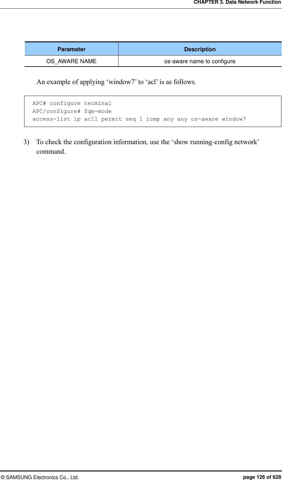
![CHAPTER 3. Data Network Function © SAMSUNG Electronics Co., Ltd. page 125 of 628 os-aware ‘window7’ modification: APC# configure terminal APC/configure# os-aware APC/configure/os-aware # os-aware window7 seq 8 dhcp-option 2 eq FF os-type windows os-aware ‘window7’ deletion: APC# configure terminal APC/configure# os-aware APC/configure/os-aware # no os-aware window7 3) Check the settings by using the ‘show OS-AWARE-all’ or ‘show OS-AWARE-[OS_AWARE NAME]’ commands. ‘show OS-AWARE-all’ retrieves all OS-AWARE information and ‘show OS-AWARE-[OS_AWARE NAME]’ only retrieves user defined information out of all OS-AWARE information. =============================================================================================== PLD_INDEX OS_NAME TYPE REFCNT OPTION LENGTH FINGERPRINT OS_TYPE =============================================================================================== 1 window7 0 0 5 2 1234 windows 3.5.6.2 Applying to ACL Configuration using CLI 1) Go to configure fqm mode to set the ACL rule of CLI. APC# configure terminal APC/configure# fqm-mode 2) Apply the OS-AWARE to ACL. Use the ‘no’ parameter to delete the OS-AWARE access-list [ip/ipv6/mac] [ACL_NAME] [deny/permit/time-profile] seq [seq_NUM] [1/*/ahp/eigrp/esp/gre/icmp/igmp/igrp/ip/nos/ospf/pcp/pim/17/6/tcp/udp/1-255] [any/A.B.C.D A.B.C.D] eq [eq_VALUE] [any/A.B.C.D A.B.C.D] eq [eq_VALUE] os-aware[OS_AWARE NAME] [[[dscp [*|[0-63]]|precedence [*|[0-7])]]]|] no access-list [ip/ipv6/mac] [ACL_NAME] [deny/permit/time-profile] seq [seq_NUM] [1/*/ahp/eigrp/esp/gre/icmp/igmp/igrp/ip/nos/ospf/pcp/pim/17/6/tcp/ udp/1-255] [any/A.B.C.D A.B.C.D] eq [eq_VALUE] [any/A.B.C.D A.B.C.D] eq [eq_VALUE] os-aware[OS_AWARE NAME] [[[dscp [*|[0-63]]|precedence [*|[0-7])]]]|]](https://usermanual.wiki/Samsung-Electronics-Co/WEA463E.Part-1/User-Guide-2696662-Page-125.png)
![CHAPTER 3. Data Network Function © SAMSUNG Electronics Co., Ltd. page 130 of 628 3.8 IGMP Snooping Configuration using CLI Use the ‘ip igmp snooping’ command to enable or disable Internet Group Management Protocol (IGMP) Snooping. ip igmp snooping no ip igmp snooping When this command is executed in the Configure mode, the IGMP Snooping of a bridge is enabled or disabled. If it is executed in the interface mode, the IGMP Snooping of an interface is enabled or disabled. Configuring the IGMP Snooping of a bridge: WEC8500# configure terminal WEC8500/configure# ip igmp snooping Configuring the IGMP Snooping of a VLAN interface: WEC8500# configure terminal WEC8500/configure# interface vlan1.10 WEC8500/configure/interface vlan1.10# ip igmp snooping In addition, a specific function of the IGMP Snooping functions of a VLAN interface can be enabled or disabled as shown in the below command. [ip igmp snooping fast-leave] This command enables or disables the Fast-Leave function. (Default: Enable status) ip igmp snooping fast-leave no ip igmp snooping fast-leave [ip igmp snooping querier] This command enables or disables the Querier function. (Default: Enable status) ip igmp snooping querier no ip igmp snooping querier [ip igmp snooping report-suppression] This command enables or disables the Report-suppression function. (Default: Enable status) ip igmp snooping report-suppression no ip igmp snooping report-suppression](https://usermanual.wiki/Samsung-Electronics-Co/WEA463E.Part-1/User-Guide-2696662-Page-130.png)
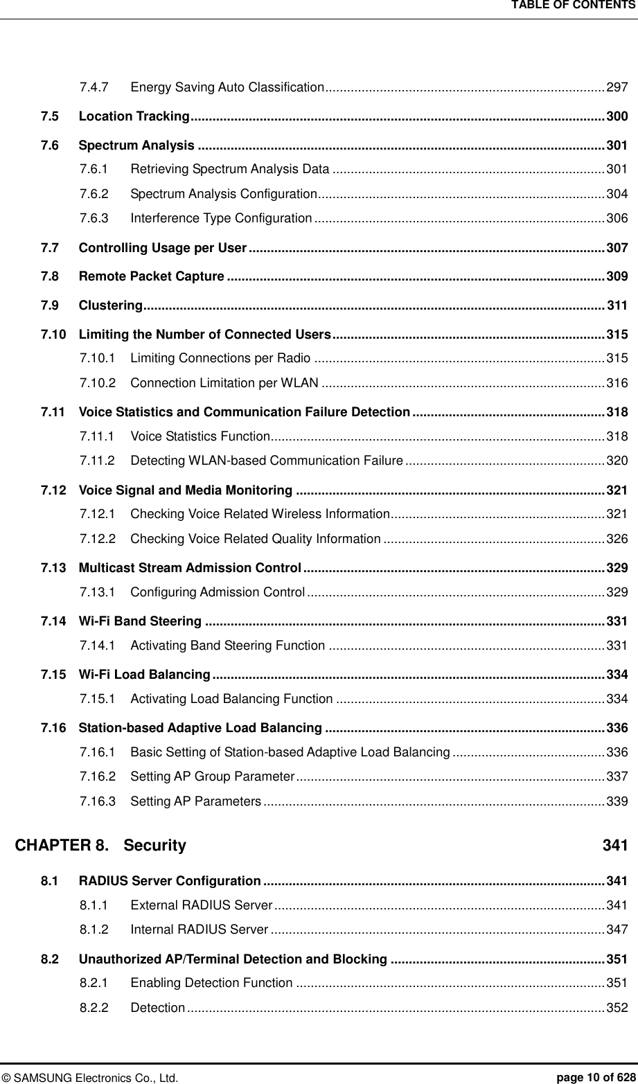
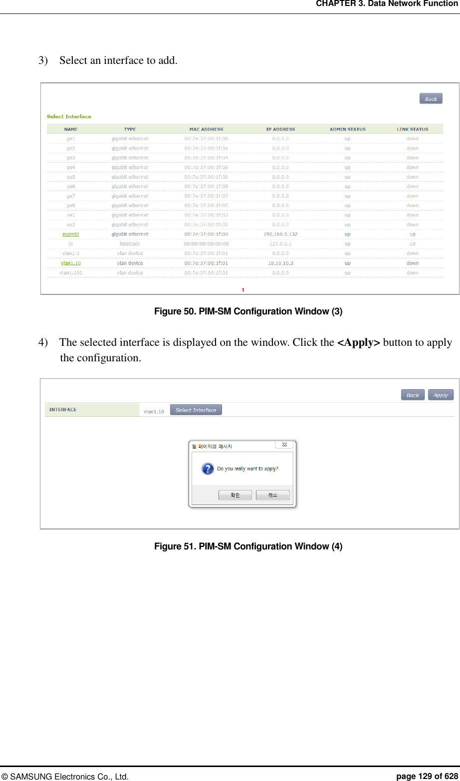
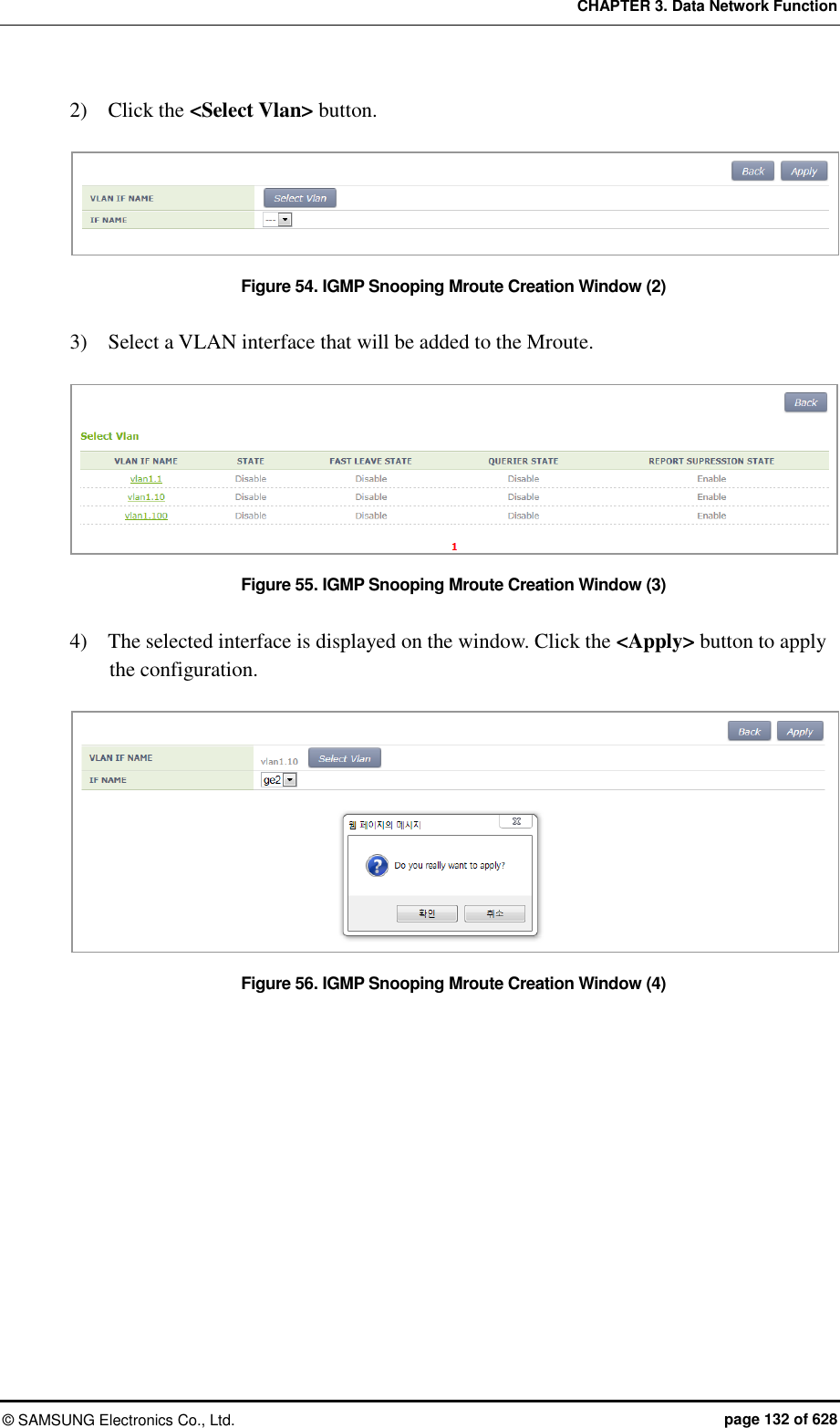
![CHAPTER 3. Data Network Function © SAMSUNG Electronics Co., Ltd. page 131 of 628 [ip igmp snooping mroute] This command enables or disables the Mroute function. ip igmp snooping mroute [INTERFACE] no ip igmp snooping mroute [INTERFACE] Configuration using Web UI In the menu bar of <WEC Main window>, select <Configuration> and then select the <Controller> <Multicast> <IGMP Snooping> menu in the sub-menus. [Config] Enables or disables the IGMP Snooping function or configures related functions. To perform configuration for STATE, FAST LEAVE, QUERIER STATE, or REPORT SUPRESSION STATE, select Enable or Disable and click the <Apply> button. Figure 52. IGMP Snooping Config Window [Mroute] The PIM-SM initial window is shown below. When you click the <Add> or <Delete> button, you can add or delete PIM-SM configuration. Figure 53. IGMP Snooping Mroute Creation Window (1) 1) In the PIM-SM initial window, click the <Add> button.](https://usermanual.wiki/Samsung-Electronics-Co/WEA463E.Part-1/User-Guide-2696662-Page-131.png)
![CHAPTER 3. Data Network Function © SAMSUNG Electronics Co., Ltd. page 133 of 628 3.9 Deep Packet Inspection It supports QoS by application. It may allow drop, bandwidth contract, and DSCP marking and it provides statistics by detailed category. The application of DPI in a unit of WLAN is possible and it also provides a monitoring function. 3.9.1 Configuring Profile and Application Rule A profile is a set of application rules and each rule includes the QoS settings of the application. The profile must set at least one application rule. Configuration using CLI 1) Enter the DPI Configuration mode. APC# configure terminal APC/configure# dpi APC/configure/dpi# 2) Make a profile and add an application rule. APC/configure/dpi# profile [NAME] APC/configure/dpi/profile [NAME]# rule [APPLICATION] APC/configure/dpi/profile [NAME]/rule [APPLICATION]# action permit APC/configure/dpi/profile [NAME]/rule [APPLICATION]# mark [DSCP] APC/configure/dpi/profile [NAME]/rule [APPLICATION]# bw-contract upstream [BW_CNT] APC/configure/dpi/profile [NAME]/rule [APPLICATION]# bw-contract downstream [BW_CNT] APC/configure/dpi/profile [NAME]# enable Parameter Description NAME Profile name APPLICATION Application name DSCP DSCP value BW_CNT Bandwidth Contract. Kbps 3) Designate a WLAN where the profile is applied. APC# configure terminal APC/configure# wlan [ID] APC/configure/wlan [ID]# dpi-profile [NAME]](https://usermanual.wiki/Samsung-Electronics-Co/WEA463E.Part-1/User-Guide-2696662-Page-133.png)
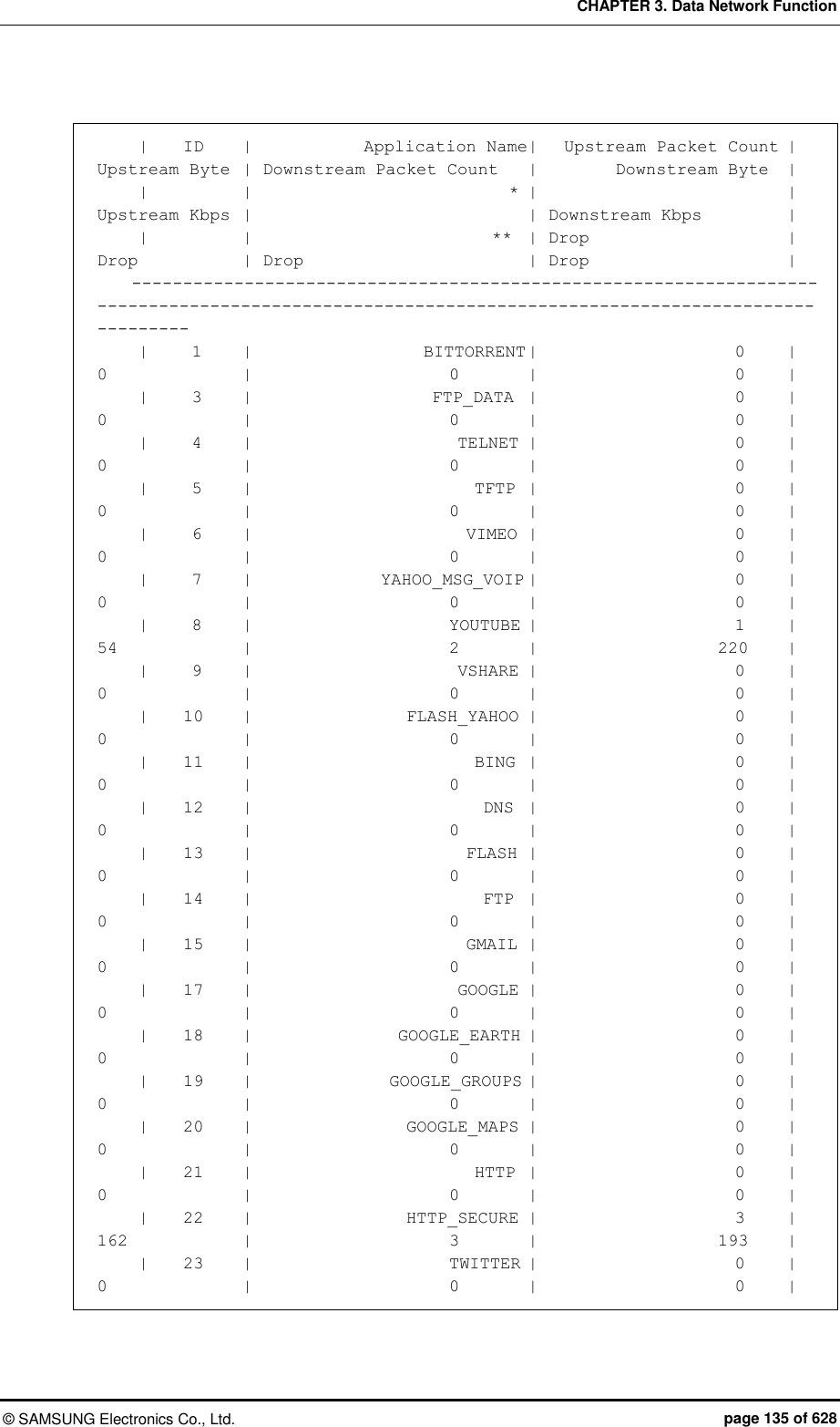
![CHAPTER 3. Data Network Function © SAMSUNG Electronics Co., Ltd. page 134 of 628 Parameter Description NAME Profile name ID WLAN ID 3.9.2 Configuring Application Group Possible to configure one or more applications as a group. Configuration using CLI 1) Enter the DPI Configuration mode. APC# configure terminal APC/configure# dpi APC/configure/dpi# 2) Make a group and add an application. APC/configure/dpi# app-group [NAME] APC/configure/dpi/app-group [NAME]# application [APPLICATION] Parameter Description NAME Group name APPLICATION Application name 3.9.3 Checking Statistics by Category The category provides statistical information by application, WLAN, station, device-os-type, and group. Configuration using CLI 1) Check the statistical information on all applications. APC# show dpi stat application Accumulated Application Stat --------------------------------------------------------------------------------------------------------------------------------------------------](https://usermanual.wiki/Samsung-Electronics-Co/WEA463E.Part-1/User-Guide-2696662-Page-134.png)
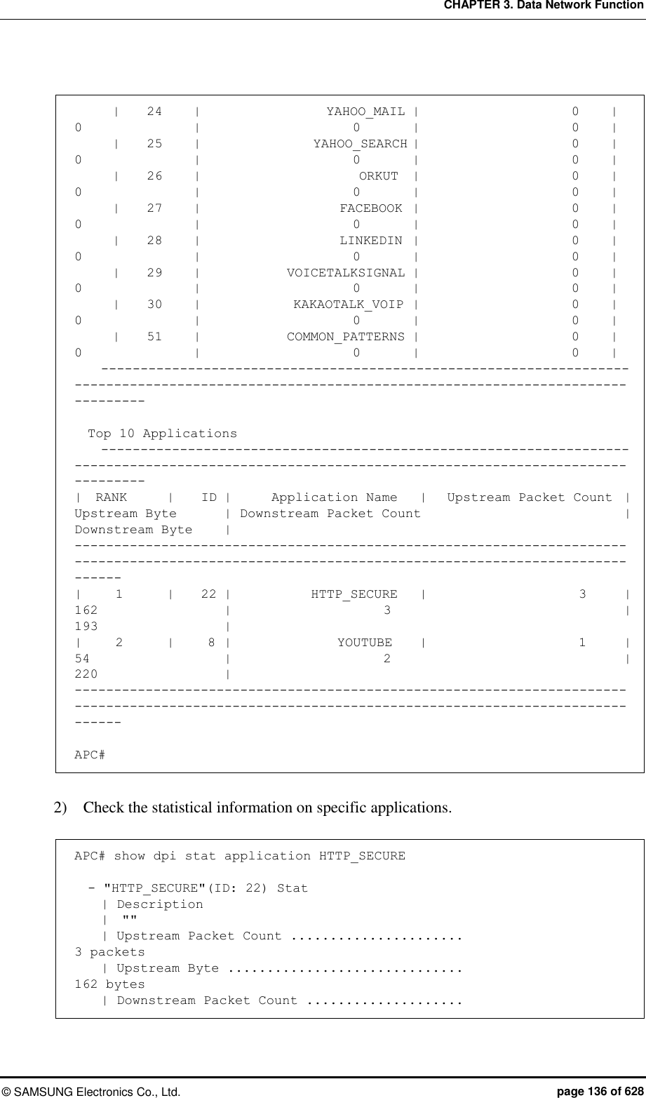
![CHAPTER 3. Data Network Function © SAMSUNG Electronics Co., Ltd. page 137 of 628 3 packets | Downstream Byte ............................ 193 bytes | Upstream Packet Drop Count ................. 0 packets | Upstream Drop Byte ......................... 0 bytes | Downstream Packet Drop Count ............... 0 packets | Downstream Drop Byte ....................... 0 bytes | | Top 10 Stations |----1----2----3----4----5----6----7----8----9---|% | 1. 00:12:47:F3:CF:A4 100.00% 355 bytes |||||||||||||||||||||||||||||||||||||||||||||||||| | | Top 10 Stations(History) |----1----2----3----4----5----6----7----8----9---|% | | Top 10 WLANs |----1----2----3----4----5----6----7----8----9---|% | 1. 1 100.00% 355 bytes |||||||||||||||||||||||||||||||||||||||||||||||||| | | Top 10 Device types |----1----2----3----4----5----6----7----8----9---|% | 1. Samsung SM-P900 100.00% 355 bytes |||||||||||||||||||||||||||||||||||||||||||||||||| | | Top 10 OS types |----1----2----3----4----5----6----7----8----9---|% | 1. Android 4.4.2 100.00% 355 bytes |||||||||||||||||||||||||||||||||||||||||||||||||| APC# Parameter Description APPLICATION Application name 3) Check the statistical information on all WLANs. APC# show dpi stat wlan 4 ) Check the statistical information on specific WLANs. APC# show dpi stat wlan [ID]](https://usermanual.wiki/Samsung-Electronics-Co/WEA463E.Part-1/User-Guide-2696662-Page-137.png)
![CHAPTER 3. Data Network Function © SAMSUNG Electronics Co., Ltd. page 138 of 628 Parameter Description ID WLAN ID 5) Check the statistical information on all stations. APC# show dpi stat station 6) Check the statistical information on specific stations. APC# show dpi stat station [MAC] 파라미터 설명 MAC Station MAC 7) Check the statistical information on all device-os-types. APC# show dpi stat device-os-type 8) Check the statistical information on specific device-os-types. APC# show dpi stat device-os-type [TYPE] Parameter Description TYPE Device of OS type name 9) Check the statistical information on all application groups. APC# show dpi stat group 10) Check the statistical information on specific application groups. APC# show dpi stat group [NAME] Parameter Description NAME Application group name](https://usermanual.wiki/Samsung-Electronics-Co/WEA463E.Part-1/User-Guide-2696662-Page-138.png)
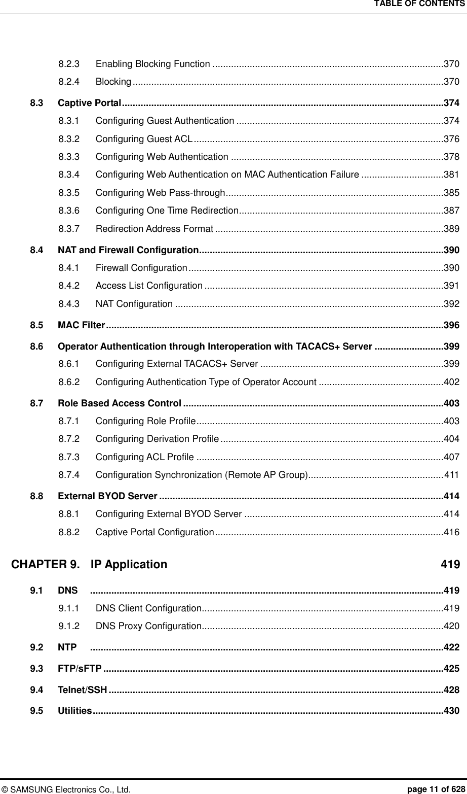
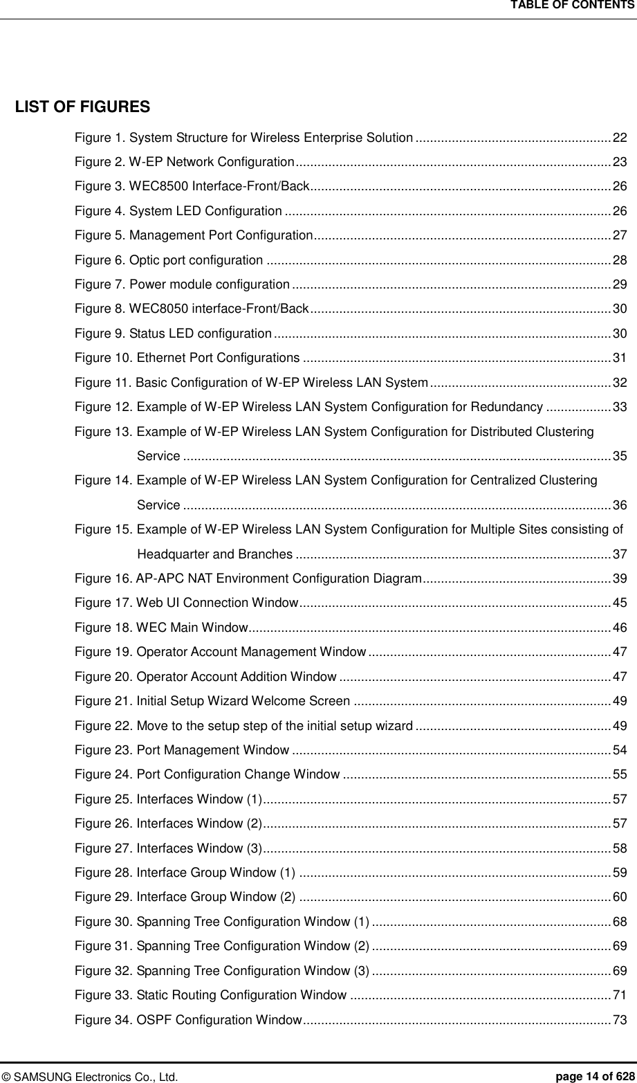
![CHAPTER 4. AP Connection Management © SAMSUNG Electronics Co., Ltd. page 140 of 628 Configuration using CLI The procedures for configuration are as follows. 1) Go to configure mode of CLI. WEC8500# configure terminal WEC8500/configure# apc WEC8500/configure/apc/apc-list# 2) Go to the apc-list item of CLI. WEC8500/configure# apc WEC8500/configure/apc/apc-list# 3) Add, delete or change APC. add-apc [APC_NAME] [MAC_ADDRESS] del-apc [APC_NAME] change-apc [CURRENT_APC_NAME] [NEW_APC_NAME] change-mac [APC_NAME] [MAC_ADDRESS] Parameter Description APC_NAME APC name CURRENT_APC_NAME Current APC name (before change) NEW_APC_NAME APC name after change IP_ADDRESS APC MAC address (xx:xx:xx:xx:xx:xx) In the APC system, enter the system mac address output parameter value of ‘show system info’ command.) 4) To check the configured APC list, execute the ‘show apc-list’ command. Configuration using Web UI In the menu bar of <WEC Main window>, select <Configuration> and then select the <Controller> <APC Lists> menu in the sub-menus. Operator can add a new APC by clicking the <Add> button in the figure. Figure 57. APC List Management Window](https://usermanual.wiki/Samsung-Electronics-Co/WEA463E.Part-1/User-Guide-2696662-Page-140.png)
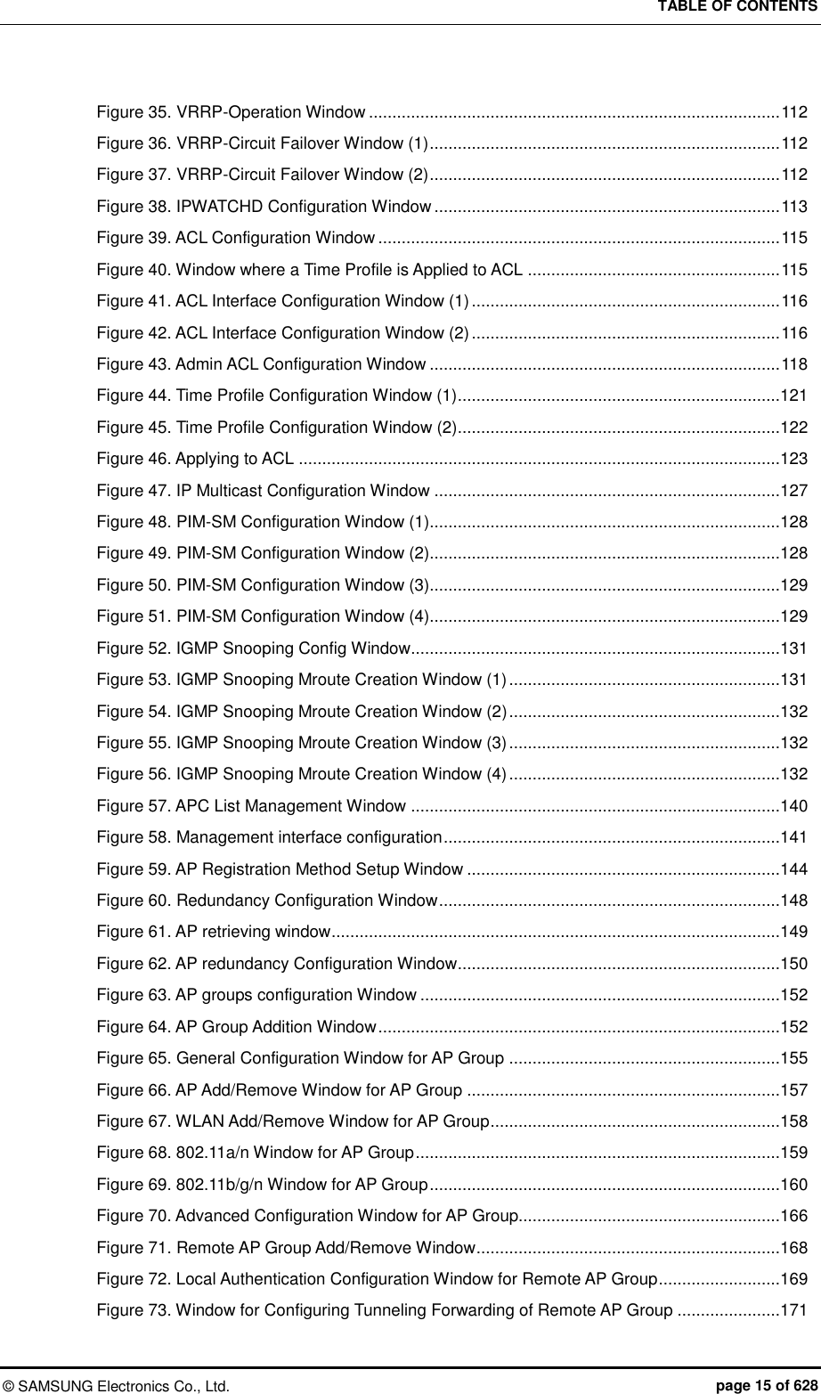
![CHAPTER 4. AP Connection Management © SAMSUNG Electronics Co., Ltd. page 141 of 628 4.1.2 Management Interface Configuration The APC can communicate with a W-EP wireless LAN AP using management interface. This is one of the information that must be configured first of all for wireless LAN service. Configuration using CLI To configure management interface, execute the command as follows: 1) Go to configure mode of CLI. WEC8500# configure terminal WEC8500/configure# 2) Configure a management interface. apc ap-mgmt-if [IP_ADDRESS] Parameter Description IP_ADDRESS IP address of APC that is used for communication with a W-EP wireless LAN AP 3) To check the configured IP information, use the ‘show apc summary’ command. Configuration using Web UI In the menu bar of <WEC Main window>, select <Configuration> and then select the <Controller> <General> menu in the sub-menus. After entering a configuration in the AP Management of the window, click the <Apply> button. Figure 58. Management interface configuration](https://usermanual.wiki/Samsung-Electronics-Co/WEA463E.Part-1/User-Guide-2696662-Page-141.png)
![CHAPTER 4. AP Connection Management © SAMSUNG Electronics Co., Ltd. page 142 of 628 4.1.3 CAPWAP Configuration A secured tunnel is created between APC and W-EP wireless LAN AP using Control And Provisioning Wireless Access Point (CAPWAP), i.e. a standard protocol, and data is transmitted through the tunnel. An encrypted data is used for both wire and wireless sections, high security is provided. The CAPWAP channel consists of control channel and data channel depending on the type of packet being transmitted/received. The control channel handles provisioning and configuration/control messages and the data channel transmits the data traffic exchanged with a wireless terminal through CAPWAP tunneling. Because the control channel transmits the wireless LAN configuration information, there should be no data loss. Therefore, the re-transmission function is basically provided. In addition, the Datagram Transmission Layer Security (DTLS) is mandatorily used for the security of transmitted data. Meanwhile, as user data traffic is transmitted through the data channel, a faster response is preferred instead of packet transmission reliability. Therefore, the re-transmission function is not provided and the DTLS function is also optional. For CAPWAP configuration, execute the following commands. 1) Go to configure apc capwap of CLI. WEC8500# configure terminal WEC8500/configure# apc WEC8500/configure/apc/capwap# WEC8500# configure terminal WEC8500/configure# apc WEC8500/configure/apc/capwap# 2) Configure the CAPWAP function using the following commands. add-multicast-if [VLAN_ID]: Configure a VLAN ID for multicast interface. auto-discovery: Configures the function of automatically detecting and registering an AP. auto-discovery-ap-group [AP_GROUP_ID]: Configures an AP group that will be working when an AP is automatically registered. change-state-pending-timer [TIMER]: Configures the maximum waiting time until the APC receives the Change State Event Request message from an AP after transmitting the Configuration Status Response message to the AP (RFC 5415). ctr-src-port [port]: Changes the CAPWAP Control port (RFC5415). date-check-timer [TIMER]: Configures the maximum waiting time until the APC receives Data Channel Keep-alive (default: 30 seconds) discovery-by-broadcast: Configures whether to allow connection to CAPWAP broadcast.](https://usermanual.wiki/Samsung-Electronics-Co/WEA463E.Part-1/User-Guide-2696662-Page-142.png)
![CHAPTER 4. AP Connection Management © SAMSUNG Electronics Co., Ltd. page 143 of 628 discovery-by-multicast: Configures whether to allow connection to CAPWAP multicast. (The ‘add-multicast-if’ must be configured before configuring whether to allow multicast connection.) discovery-del-timer: If the Join message is not received after receiving a Discovery message, this configures the timeout to discard the previously received Discovery messages. dtls-session-delete [TIMER]: Configures the waiting time to disconnect DTLS when releasing the connection between an AP and CAPWAP. retransmit-interval [INTERVAL]: Configures the re-transmission interval of CAPWAP control packet retransmission. max-retransmit [COUNT]: Configures maximum number of retransmission when there is no answer for CAPWAP control packet transmission. wait-dtls-timer [TIMER]: Configures the maximum time until the AP waits without receiving the DTLS handshake message from the APC (RFC 5415) (default: 60 seconds) wait-join-timer [TIMER]: Configures the maximum time until the APC receives the Join message after finishing DTLS handshake (RFC 5415) (default: 60 seconds) window-size [size]: Configures the maximum number of packets that can be transmitted without response during CAPWAP control packet transmission. An example of entering a command is shown below. WEC8500/configure/apc/capwap# date-check-timer 30 3) To check the configured CAPWAP information, use the ‘show apc capwap summary’ command.](https://usermanual.wiki/Samsung-Electronics-Co/WEA463E.Part-1/User-Guide-2696662-Page-143.png)
![CHAPTER 4. AP Connection Management © SAMSUNG Electronics Co., Ltd. page 144 of 628 4.1.4 AP Registration (Auto Discovery) Configuration The APC provides the AP auto-discovery function that automatically registers APs in the same network without having to configure any settings in advance. To configure the function, execute the following commands. Configuration using CLI 1) Go to configure apc capwap of CLI. WEC8500# configure terminal WEC8500/configure# apc WEC8500/configure/apc # capwap WEC8500/configure/apc/capwap # 2) Configure the automatic registration function. auto-discovery 3) Configure an AP group that will be working after AP automatic registration. auto-discovery-ap-group [AP_GROUP_ID] Parameter Description AP_GROUP_ID ap-group that will be working after AP automatic registration 4) To check the configured information, use the ‘show apc capwap summary’ command. Configuration using Web UI In the menu bar of <WEC Main window>, select <Configuration> and then select the <Controller> <General> menu from the sub-menus. After entering a configuration in the AP Registration of the window, click the <Apply> button. Figure 59. AP Registration Method Setup Window](https://usermanual.wiki/Samsung-Electronics-Co/WEA463E.Part-1/User-Guide-2696662-Page-144.png)
![CHAPTER 4. AP Connection Management © SAMSUNG Electronics Co., Ltd. page 145 of 628 4.1.5 Managing AP File Transmission It provides the configuration and transmission management function for the tech support file of the AP. 4.1.5.1 Tech Support Information File 1) Go to configure APC mode of CLI. WEC8500# configure terminal WEC8500/configure# apc WEC8500/configure/apc# 2) Configure a file transmission method to collect the AP Tech support information. tech-support [MODE] Parameter Description MODE Selects file transmission method (ftp/sftp/http). - tftp is not supported. 3) If AP debug information collection is failed, configure maximum number of retries. tech-support max-retry [COUNT] Parameter Description COUNT Number of retries. 4) To check the configuration information, use the ‘show ap tech-support’ command. 4.1.6 APC Redundancy Configuration An operator can add a backup APC to an AP to make the backup APC provide the service even when an APC fault occurs. The maximum number of backup APCs that can be registered to one AP per model is as follows: APC Model The maximum number of APC systems that can be registered WEC8500 3 (Primary Server, Secondary Server, Tertiary Server) WEC8050 2 (Primary Server, Secondary Server) If a fault occurs to the primary APC while an AP is connected to the primary APC, the AP is connected to the secondary APC. If a fault also occurs to the secondary APC, the AP is connected to the tertiary APC. For reference, the WEC8050 model does not support a tertiary APC.](https://usermanual.wiki/Samsung-Electronics-Co/WEA463E.Part-1/User-Guide-2696662-Page-145.png)
![CHAPTER 4. AP Connection Management © SAMSUNG Electronics Co., Ltd. page 146 of 628 Operator can also configure fallback to return to the original APC from the backup APC during the service. If the fallback operation is configured, the AP periodically performs health check to check whether the primary APC can be connected. When the connection is required, it can immediately perform fallback according to the fallback option or can perform fallback on a specified time. The reason why configuring fallback time zone is to minimize the service interruption due to fallback by making it happens when the load is low. In an APC, operator can configure the primary and backup APCs of an AP in the following steps. 1) Register APCs to the APC list. In the ‘APC List Management’, how to add the APC list is described. 2) Add the APCs in the APC list to redundancy. If necessary, configure the fallback function. And then, operator can configure the APCs added to redundancy as the primary, secondary, or tertiary server of an AP. 3) Configure a primary, secondary, and tertiary server per AP. To make an AP operate in redundancy configuration, configure the Discovery Type of the AP as ‘APC Referal’. Use the Multi-Set function of WEC to configure several APs at the same time. Configuration using CLI 1) By referring to the ‘AP List Management’, add the APC list that will be used as a backup APC. 2) After entering into the configure redundancy mode, add or delete the APCs in the APC list. If necessary, configure the fallback function. WEC8500# configure terminal WEC8500/configure# redundancy WEC8500/configure/redundancy# add-apc [APC_NAME] [IP_ADDRESS] [PORT] del-apc [APC_NAME] fallback-enable now fallback-enable at-time [FALLBACK START-END TIME] fallback-interval [INTERVAL] Parameter Description APC_NAME Name of an APC to be added or deleted to/from redundancy The APC must be an APC registered in the APC list. IP_ADDRESS IP address of an APC to add This address is an IP required by an AP to connect to the APC. Therefore, you must enter the AP Management IP address of the APC.](https://usermanual.wiki/Samsung-Electronics-Co/WEA463E.Part-1/User-Guide-2696662-Page-146.png)
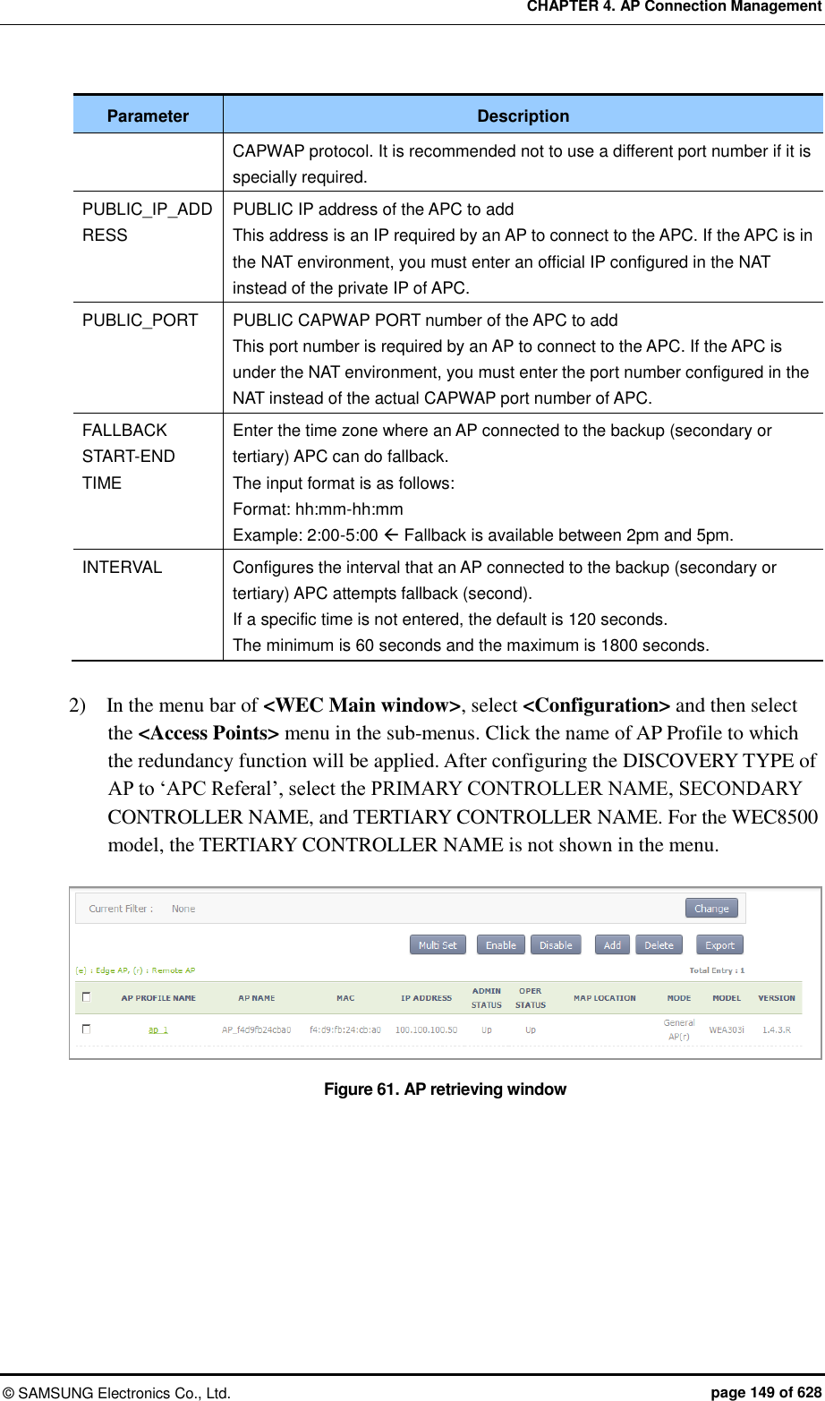
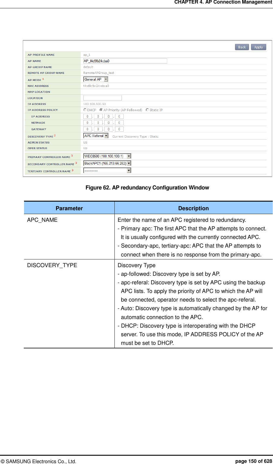
![CHAPTER 4. AP Connection Management © SAMSUNG Electronics Co., Ltd. page 147 of 628 Parameter Description PORT CAPWAP PORT number of the APC to add This port number is required by an AP to connect to the APC. If no port number is entered, it is set to 5246, the default port number of CAPWAP protocol. It is recommended not to use a different port number if it is specially required. FALLBACK START-END TIME Enter the time zone where an AP connected to the backup (secondary or tertiary) APC can do fallback. The input format is as follows: - Format: hh:mm-hh:mm - Example: 2:00-5:00 Fallback is available between 2pm and 5pm. INTERVAL Configures the interval that an AP connected to the backup (secondary or tertiary) APC attempts fallback (second). If a specific time is not entered, the default is 120 seconds. The minimum is 60 seconds and the maximum is 1800 seconds. 3) Enter into the configure AP configuration mode of CLI and configure a primary, secondary, and tertiary server. To make an AP operate in redundancy configuration, configure the Discovery of the AP as ‘apc-referal’. WEC8500# configure terminal WEC8500/configure# ap ap_1 WEC8500/configure/ap ap_1# discovery apc-referal primary-apc [APC_NAME] secondary-apc [APC_NAME] tertiary-apc [APC_NAME] Parameter Description APC_NAME Enter the name of an APC registered to redundancy. - Primary apc: The first APC that the AP attempts to connect. It is usually configured with the currently connected APC. - Secondary-apc, tertiary-apc: APC that the AP attempts to connect when there is no response from the primary-apc. DISCOVERY_TYPE Discovery Type - ap-followed: Discovery type is set by AP. - apc-referal: Discovery type is set by APC using the backup APC lists. To apply the priority of APC to which the AP will be connected, operator needs to select the apc-referal. - DHCP: Discovery type is interoperating with the DHCP server. To use this mode, IP ADDRESS POLICY of the AP must be set to DHCP. - Auto: Discovery type is automatically changed by the AP for automatic connection to the APC.](https://usermanual.wiki/Samsung-Electronics-Co/WEA463E.Part-1/User-Guide-2696662-Page-147.png)
![CHAPTER 4. AP Connection Management © SAMSUNG Electronics Co., Ltd. page 148 of 628 4) To check the configured apc list, execute the ‘show apc summary’ command. 5) To check the redundancy information, execute the ‘show redundancy summary’ command. 6) To check the configured AP profile, execute the ‘show ap detail [AP_PROFILE_ NAME]’ command. Configuration using Web UI By referring to the ‘APC List Management’, add the APC list that will be used as a backup APC. 1) In the menu bar of <WEC Main window>, select <Configuration> and then select the <Controller> <Redundancy> menu in the sub-menus. Operator can add or delete the APC list that will be used for redundancy. If necessary, operator can configure the fallback function. Figure 60. Redundancy Configuration Window Parameter Description APC NAME Name of an APC to be added or deleted to/from redundancy The APC must be an APC registered in the APC list. MAC ADDRESS Because this is a MAC address configured during registration to the APC list, an operator does not have to enter this at the redundancy configuration stage. IP_ADDRESS IP address of an APC to add This address is an IP required by an AP to connect to the APC. Therefore, you must enter the AP Management IP address of the APC. PORT CAPWAP PORT number of the APC to add If no port number is entered, it is set to 5246, the default port number of](https://usermanual.wiki/Samsung-Electronics-Co/WEA463E.Part-1/User-Guide-2696662-Page-148.png)
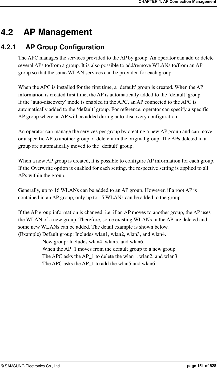
![CHAPTER 4. AP Connection Management © SAMSUNG Electronics Co., Ltd. page 152 of 628 Configuration using CLI To manage an AP group, execute the command as follows. 1) Go to configure mode of CLI. WEC8500# configure terminal WEC8500/configure# 2) Create or delete an AP group. Use ‘no’ parameter in front of the command to delete an AP group. ap-group [AP_GROUP_NAME] no ap-group [AP_GROUP_NAME] 3) Add or delete an AP to or from the AP group. Use ‘no’ parameter in front of the command to delete an AP from the AP group. But, for a default AP group, you cannot delete an AP from the group. If you delete an AP from other AP groups other than the default group, the deleted AP is included into the default AP group. add-ap [AP_NAME] no add-ap [AP_NAME] 4) Use the ‘show ap-group summary’ command to check the AP group information. Configuration using Web UI In the menu bar of <WEC Main window>, select <Configuration> and then select the <AP Groups> menu in the sub-menus. It provides the group configuration of the AP. Click the <Add> or <Delete> button to add or delete a group. Figure 63. AP groups configuration Window Figure 64. AP Group Addition Window](https://usermanual.wiki/Samsung-Electronics-Co/WEA463E.Part-1/User-Guide-2696662-Page-152.png)
![CHAPTER 4. AP Connection Management © SAMSUNG Electronics Co., Ltd. page 153 of 628 4.2.1.1 General AP Group Settings To aid management of APs in groups, the APC allows configuration of settings which can be applied commonly to each group. The following functions are provided: Parameter Description Description This configures the description of the AP group. AP Mode This configures the operation mode of the AP. The operator can select General AP, Root AP, or Repeater AP. Location This configures the installation location information of the AP. IP Mode This configures the IP configuration mode of the AP. The operator can select DHCP or AP Priority. AP Status This configures the up/down status of the AP. Redundancy If the APCs are configured for redundancy, this configures the discovery type and Primary/Secondary/Tertiary Controller settings of the AP. The APC provides the overwrite option for each AP group setting. If the Overwrite option is enabled for each setting, the respective setting is applied to all APs within the group. For example, if the Overwrite option is enabled for AP Mode and AP Mode is set to General, all the APs within the group will run as General APs. Configuration using CLI To configure redundancy settings for the AP group, perform the following commands: 1) Go to configure mode of CLI. WEC8500# configure terminal WEC8500/configure# 2) Enter the AP Group configuration mode. ap-group [AP_GROUP_NAME] 3) Enter the profile configuration mode for the AP group. Profile 4) Configure the following AP group profiles: description overwrite-ap-mode no overwrite-ap-mode ap-mode overwrite-location no overwrite-location location](https://usermanual.wiki/Samsung-Electronics-Co/WEA463E.Part-1/User-Guide-2696662-Page-153.png)
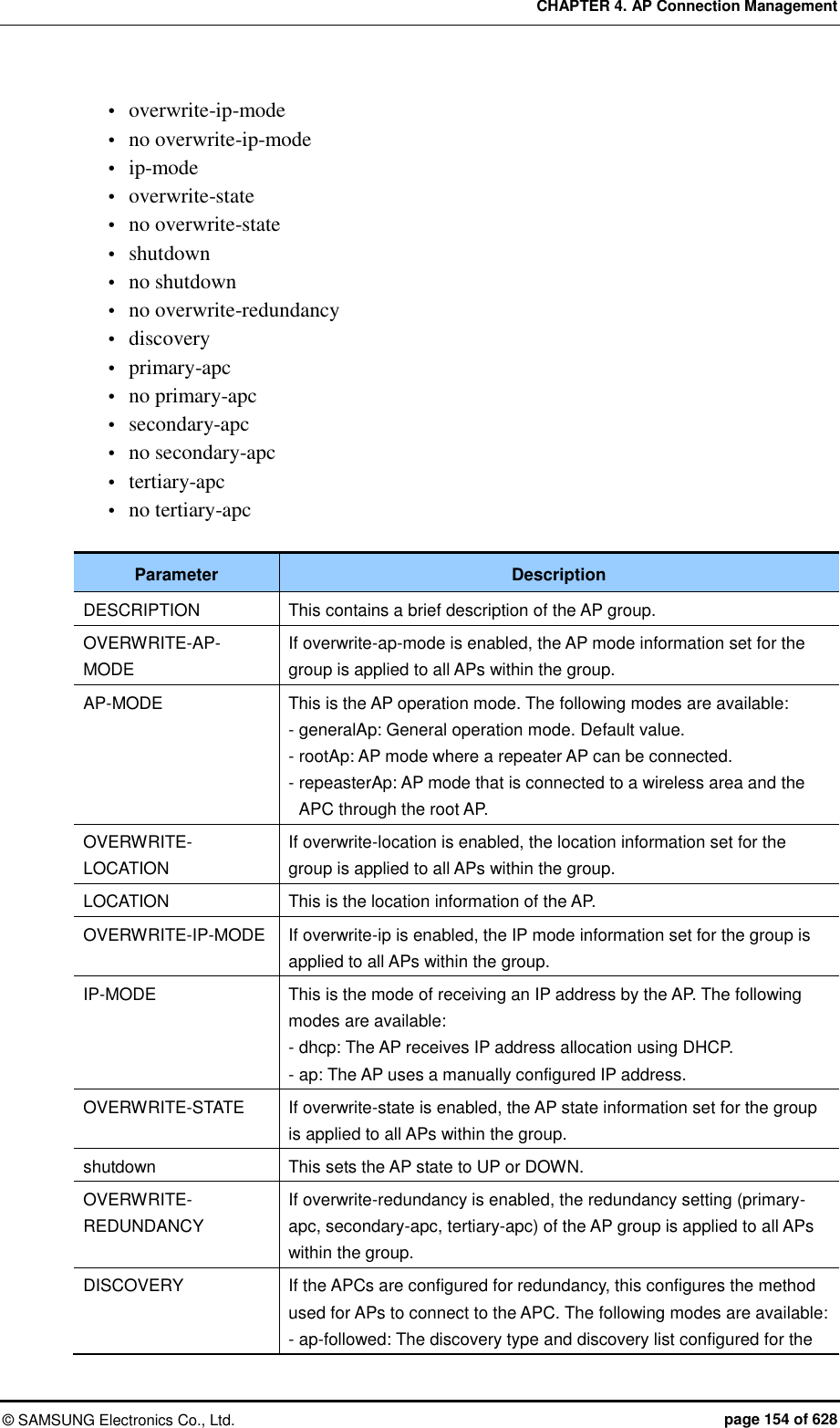
![CHAPTER 4. AP Connection Management © SAMSUNG Electronics Co., Ltd. page 155 of 628 Parameter Description AP are used. - apc-referral: The APC list configured for the APC is used as the discovery list. - DHCP: The APC list information relayed by DHCP option 138 (IPv4) or option 52 (IPv6) is used as the discovery list. - auto: Discovery type is automatically changed by the AP for automatic connection to the APC. PRIMARY-APC This is the name of the primary APC server. The AP attempts to connect to this APC first. SECONDARY-APC This is the name of the secondary APC server. If the AP is unable to connect to the primary APC, the AP attempts to connect to this APC on its second connection attempt. TERTIARY-APC This is the name of the tertiary APC server. If the AP is unable to connect to the secondary APC, the AP attempts to connect to this APC on its third connection attempt. The WEC8050 model does not support Tertiary-APC. 5) Use the ‘show ap-group detail [AP_GROUP_NAME]’ command to check the AP group information. Configuration using Web UI In the menu bar of <WEC Main Window>, select <Configuration>, select <AP Groups> in the submenu, and then select an AP group to configure. In the ‘General’ tab of the AP group, configure the necessary settings. If the OVERWRITE AP CONFIG checkbox is selected, the respective setting is applied to all APs within the group. Figure 65. General Configuration Window for AP Group](https://usermanual.wiki/Samsung-Electronics-Co/WEA463E.Part-1/User-Guide-2696662-Page-155.png)
![CHAPTER 4. AP Connection Management © SAMSUNG Electronics Co., Ltd. page 156 of 628 4.2.1.2 Adding/Removing APs To aid management of APs in groups, the APC allows addition/removal of APs to/from AP groups. Configuration using CLI 1) Go to configure mode of CLI. WEC8500# configure terminal WEC8500/configure# 2) Create an AP group or enter the AP group configuration mode. ap-group [AP_GROUP_NAME] 3) Add/remove an AP to/from the AP group. Use ‘no’ parameter in front of the command to delete an AP from the AP group. However, you cannot delete an AP from a default AP group. If you delete an AP from groups other than the default group, the deleted AP is then included in the default AP group. add-ap [AP_NAME] no add-ap [AP_NAME] 4) Use the ‘show ap-group summary’ command to check the AP group information.](https://usermanual.wiki/Samsung-Electronics-Co/WEA463E.Part-1/User-Guide-2696662-Page-156.png)
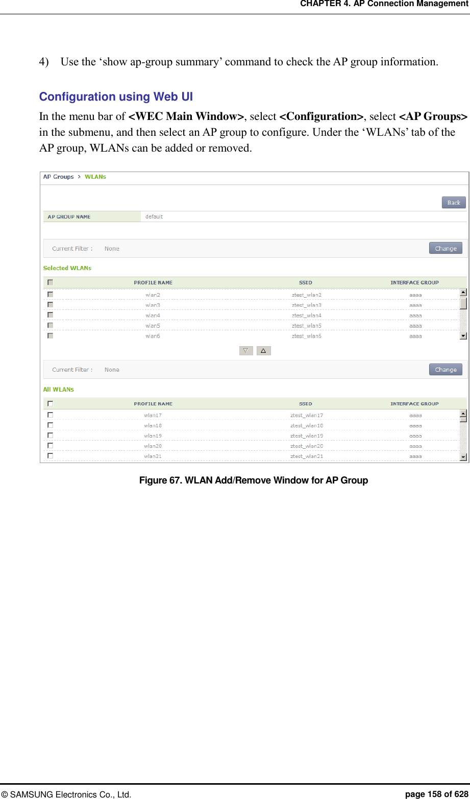
![CHAPTER 4. AP Connection Management © SAMSUNG Electronics Co., Ltd. page 157 of 628 Configuration using Web UI In the menu bar of <WEC Main Window>, select <Configuration>, select <AP Groups> in the submenu, and then select an AP group to configure. Under the ‘APs’ tab of the AP group, APs can be added or removed. Figure 66. AP Add/Remove Window for AP Group 4.2.1.3 Adding/Removing WLANs To allows the same WLAN services to be provided to the APs allocated to each group, the APC allows addition/removal of WLANs to/from each AP group. Configuration using CLI 1) Go to configure mode of CLI. WEC8500# configure terminal WEC8500/configure# 2) Create an AP group or enter the AP group configuration mode. ap-group [AP_GROUP_NAME] 3) Add/remove an WLAN to/from the AP group. Use ‘no’ parameter in front of the command to delete an WLAN from the AP group. add-wlan [WLAN_ID] no add-wlan [WLAN_ID]](https://usermanual.wiki/Samsung-Electronics-Co/WEA463E.Part-1/User-Guide-2696662-Page-157.png)
![CHAPTER 4. AP Connection Management © SAMSUNG Electronics Co., Ltd. page 159 of 628 4.2.1.4 802.11a/n Configuration Configuration using Web UI In the menu bar of <WEC Main Window>, select <Configuration>, select <AP Groups> in the submenu, and then select an AP group to configure. Settings can be configured under the ‘802.11a/n’ tab of the AP group. Figure 68. 802.11a/n Window for AP Group The configuration items are as follows: [Service Configuration of AP Group] SERVICE: Enable or disable the radio service. [Channel Configuration] CURRENT CHANNEL: Channel configuration (range: 36-165) CHANNEL FIX: The configured channel is configured as fixed and it is not affected by automatic adjustment functions such as RRM. When the <Monitor> <Access Points> <Radio> <802.11a/n/ac> menu is selected, the channel value is shown as * (optional). [TX Power Setting] TX CURRENT POWER: TX power (range: 3-23) TX POWER FIX: The configured TX power is configured as fixed and it is not affected by automatic adjustment functions such as RRM. When the <Monitor> <Access Points> <Radio> <802.11a/n/ac> menu is selected, the TxPower value is shown as * (optional). To check the configured channel and TX power information, go to <Monitor> <Access Points> <Radio> <802.11a/n/ac>.](https://usermanual.wiki/Samsung-Electronics-Co/WEA463E.Part-1/User-Guide-2696662-Page-159.png)
![CHAPTER 4. AP Connection Management © SAMSUNG Electronics Co., Ltd. page 160 of 628 4.2.1.5 802.11b/g/n Configuration Configuration using Web UI In the menu bar of <WEC Main Window>, select <Configuration>, select <AP Groups> in the submenu, and then select an AP group to configure. Settings can be configured under the ‘802.11b/g/n’ tab of the AP group. Figure 69. 802.11b/g/n Window for AP Group The configuration items are as follows: [Service Configuration of AP Group] SERVICE: Enable or disable the radio service. [Channel Configuration] CURRENT CHANNEL: Channel configuration (range: 1-14) CHANNEL FIX: The configured channel is configured as fixed and it is not affected by automatic adjustment functions such as RRM. When the <Monitor> <Access Points> <Radio> <802.11b/g/n> menu is selected, the channel value is shown as * (optional). [TX Power Setting] TX CURRENT POWER: TX power (range: 3-23) TX POWER FIX: The configured TX power is configured as fixed and it is not affected by automatic adjustment functions such as RRM. When the <Monitor> <Access Points> <Radio> <802.11b/g/n> menu is selected, the TxPower value is shown as * (optional). To check the configured channel and TX power information, go to <Monitor> <Access Points> <Radio> <802.11b/g/n>.](https://usermanual.wiki/Samsung-Electronics-Co/WEA463E.Part-1/User-Guide-2696662-Page-160.png)
![CHAPTER 4. AP Connection Management © SAMSUNG Electronics Co., Ltd. page 161 of 628 4.2.1.6 Advanced Configuration In order to provide the same services to the APs allocated to each group, the APC allows configuration of advanced settings for each AP group. Configuring AP Group Profile with CLI 1) Go to configure mode of CLI. WEC8500# configure terminal WEC8500/configure# 2) Create an AP group or enter the AP group configuration mode. ap-group [AP_GROUP_NAME] 3) Enter the profile configuration mode for the AP group. profile 4) Configure the following AP group profiles: overwrite-apc-ap-timer no overwrite-apc-ap-timer echo-interval discovery-interval report-interval statistics-timer retransmit-interval echo-retransmit-interval max-echo-retransmit overwrite-telnet-ssh no overwrite-telnet-ssh telnet-enable no telnet-enable ssh-enable no ssh-enable overwrite-console no overwrite-console console-enable no console-enable overwrite-dtls no overwrite-dtls dtls-policy overwrite-led-control no overwrite-led-control led-config](https://usermanual.wiki/Samsung-Electronics-Co/WEA463E.Part-1/User-Guide-2696662-Page-161.png)
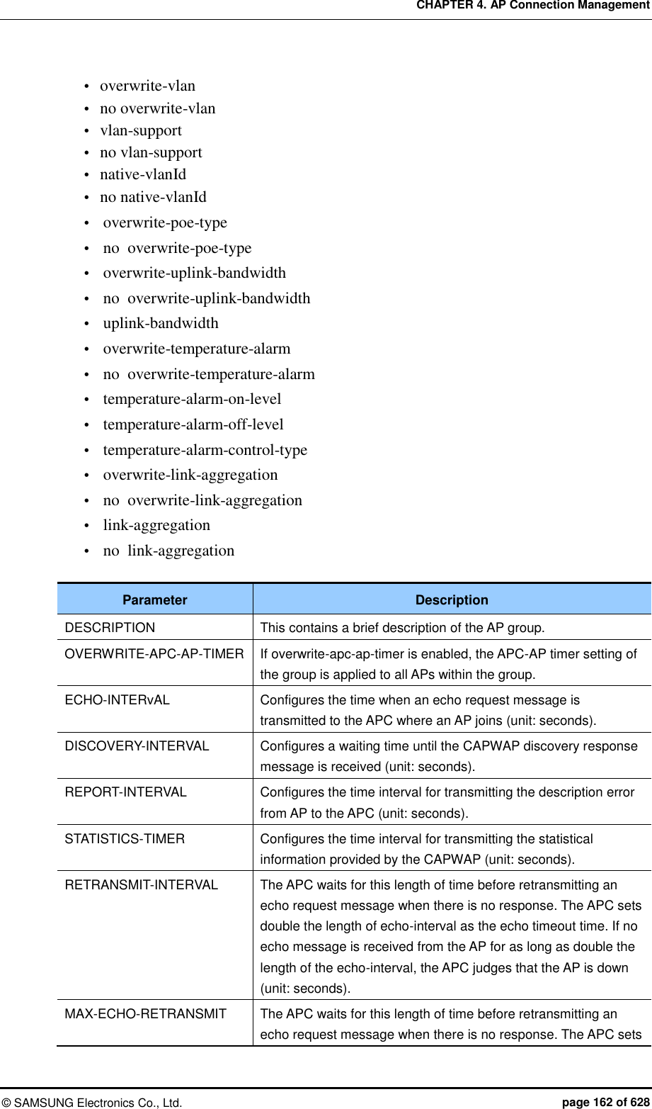
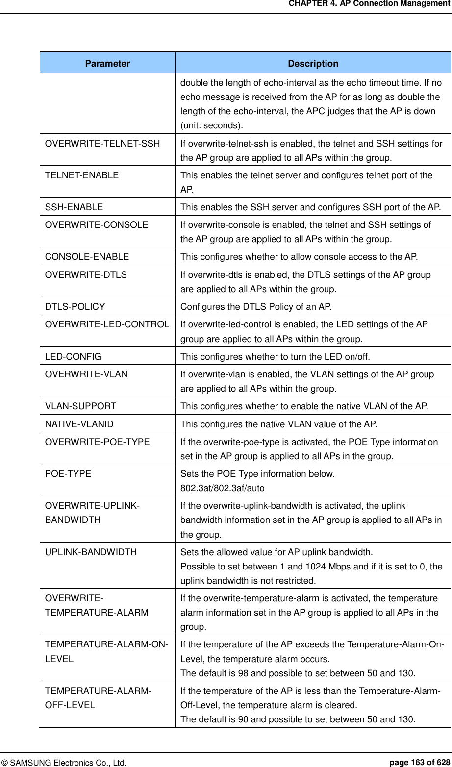
![CHAPTER 4. AP Connection Management © SAMSUNG Electronics Co., Ltd. page 164 of 628 Parameter Description TEMPERATURE-ALARM-CONTROL-TYPE If the temperature alarm occurs, whether the radio of the AP is set to be off or on. OVERWRITE-LINK-AGGREGATION If the overwrite-link-aggregation is activated, the link aggregation information set in the AP group is applied to all APs in the group. LINK-AGGREGATION In case of an AP model for 802.11ac, provide two uplink Ethernet ports. Possible to set link aggregation for two Ethernet ports. If link aggregation is activated, possible to set the following mode: - Both (Destination + Source) - Destination - Source 5) Use the ‘show ap-group detail [AP_GROUP_NAME]’ command to check the AP group information. Configuring AirMove Service of AP Group with CLI 1) Go to configure mode of CLI. WEC8500# configure terminal WEC8500/configure# 2) Create an AP group or enter the AP group configuration mode. ap-group [AP_GROUP_NAME] 3) Enter the profile configuration mode for the AP group. profile 4) Configure the AirMove service of the AP group. enable: Enables/disables the AirMove service. target-ap: This option is used for selecting APs which will be applied with the changes made to the group settings. If 'all' is selected, changes are applied to all APs and config priority of the APs also change to group. If 'keep-ap-config' is selected, only the APs whose config priority is set to group have the airmove value of the group applied to them. WEC8500# configure terminal WEC8500/configure# ap-group default GroupName : default WEC8500/configure/ap-group default# airmove WEC8500/configure/ap-group default/airmove# ? decision-delta Set delta value for handover decision enable Airmove enable exit Exit from airmove mode](https://usermanual.wiki/Samsung-Electronics-Co/WEA463E.Part-1/User-Guide-2696662-Page-164.png)
![CHAPTER 4. AP Connection Management © SAMSUNG Electronics Co., Ltd. page 165 of 628 number-of-channel Set the number of channel required during one time scanning number-of-proreq Set the number of probe request required during one time scanning scan-time-channel Set time required for one channel scanning scan-time-interleave Set interval time required for new scanning start scan-time-service Set time required for STA service during STA’s scanning scan-trigger-level Set a trigger level for STA's scanning start target-ap Set config target ap <cr> WEC8500/configure/ap-group default/airmove# enable ? <cr> WEC8500/configure/ap-group default/airmove# decision-delta ? 1 - 100 Enter the value [dBm] WEC8500/configure/ap-group default/airmove# number-of-channel ? 1 - 20 Enter the number WEC8500/configure/ap-group default/airmove# number-of-proreq ? 1 - 10 Enter the number WEC8500/configure/ap-group default/airmove# scan-time-channel ? 0 - 100 Enter the time [ms] WEC8500/configure/ap-group default/airmove# scan-time-interleave ? 1000 - 10000 Enter the time [ms] WEC8500/configure/ap-group default/airmove# scan-time-service ? 1 - 1000 Enter the time [ms] WEC8500/configure/ap-group default/airmove# scan-trigger-level ? -128 - 0 Enter the trigger level [dBm] WEC8500/configure/ap-group default/airmove# target-ap ? all All keep-ap-config Keep ap config WEC8500/configure/ap-group default/airmove# end 4) Use the ‘show airmove group [ap_group_name]’ command to check the AP group information. WEC8500# show airmove group default Airmove Group Configurations ---------------------------- Airmove State Disable Target AP Keep Ap Config Scan trigger level -70 dBm Scanning time for one channel 5 ms Service time during scanning 100 ms Scanning interval time 1000 ms Number of probe requests 2 Number of scanning channels 4](https://usermanual.wiki/Samsung-Electronics-Co/WEA463E.Part-1/User-Guide-2696662-Page-165.png)
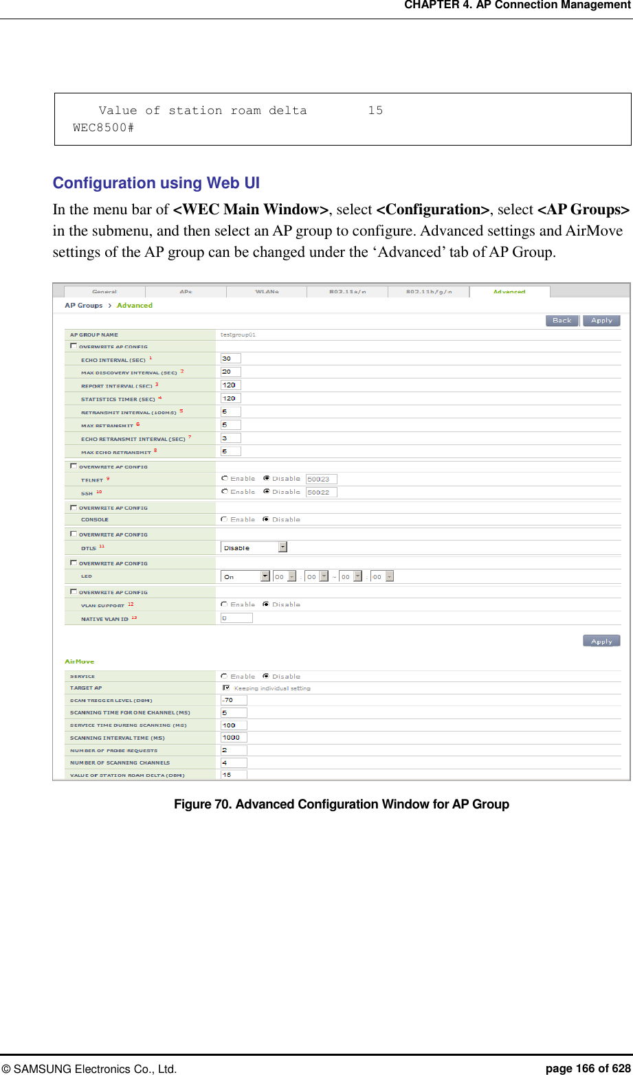
![CHAPTER 4. AP Connection Management © SAMSUNG Electronics Co., Ltd. page 167 of 628 4.2.2 Configuring Remote AP Group If the APs are located in an area where the APC is not located, those APs must be classified into a separate group for service. The APC can manage the APs in another area by grouping them into a remote AP group. In the Remote AP group, the operator can configure the below information and the APs in the Remote AP group are operating based on the same configuration. Addition/Deletion of Remote AP Possible to add or delete APs to be included in the remote AP group. Local Authentication Radius Server Possible to set a Radius server which will authenticate a station connecting to the remote AP. Remote AP User List Possible to add or delete a user (station) to be managed in the remote AP. Role Based Access Control Possible to apply the ACL profile. Tunnel Forwarding Possible to add the split tunnel ACL settings of the WLAN set with the tunneling mode. Local Bridging Forwarding Possible to add settings of VLAN ID, ACL, and Pre-Auth ACL of the WLAN set with the local bridging mode. When an AP group is added and the remote AP group is checked, APs included in the AP group operates in the remote AP mode. If an AP is added to or deleted from a remote AP group, the AP is rebooted and reconnected to the APC. If an AP moves between remote AP groups, the AP is not rebooted. 4.2.2.1 Addition/Removal Setting Configuration using CLI 1) Go to configure mode of CLI. WEC8500# configure terminal WEC8500/configure# 2) Create an AP group. ap-group[REMOTE_AP_GROUP_NAME]](https://usermanual.wiki/Samsung-Electronics-Co/WEA463E.Part-1/User-Guide-2696662-Page-167.png)
![CHAPTER 4. AP Connection Management © SAMSUNG Electronics Co., Ltd. page 168 of 628 3) Designate remote AP group properties to the AP group. group-type remote 4) When the remote AP group is deleted, use the 'no' parameter in front of the ap-group command to delete the remote AP group. no ap-group[REMOTE_AP_GROUP_NAME] Configuration using Web UI In the menu bar of <WEC Main Window>, select <Configuration> and then select the <AP Groups> menu in the sub-menus. Click the <Add> or <Delete> button to add or delete a group. Figure 71. Remote AP Group Add/Remove Window 4.2.2.2 Local Authentication Configuration for Remote AP Group Users (stations) accessing the remote AP and the Radius server which authenticates such users can be configured. Configuration using CLI To configure the local authentication of the remote AP group, perform the command as follows: 1) Go to configure Remote AP Group configuration mode of CLI. WEC8500# configure terminal WEC8500/configure# WEC8500/configure/ap-group {remote-ap-group-name} WEC8500/configure/ap-group/{remote-ap-group-name}#remote 2) Configure Primary Radius Server 1, Primary Radius Server 2, and Primary Radius Server 3. The RADIUS server information must be created in the radius of the security item in advance. To delete the configured RADIUS server information, enter ‘no’ parameter in front of the command. remote primary-radius[RADIUS_SERVER_INDEX] no remote primary-radius[RADIUS_SERVER_INDEX] remote secondary-radius[RADIUS_SERVER_INDEX]](https://usermanual.wiki/Samsung-Electronics-Co/WEA463E.Part-1/User-Guide-2696662-Page-168.png)
![CHAPTER 4. AP Connection Management © SAMSUNG Electronics Co., Ltd. page 169 of 628 no remote secondary-radius[RADIUS_SERVER_INDEX] remote tertiary-radius[RADIUS_SERVER_INDEX] no remote tertiary-radius[RADIUS_SERVER_INDEX] 3) Add or delete users (stations) connecting to the remote AP. add-user [USER NAME] no add-user [USER NAME] 4) Execute the ‘show remote-ap-group detail [REMOTE AP GROUP NAME]’ command to check the AP group information. Configuration using Web UI In the menu bar of <WEC Main window>, select <Configuration> and then select the <AP Groups> menu in the sub-menus. After selecting the name of a remote AP group, configure a Radius server or add or delete users in "User Authentication" item of the ‘Remote AP Group’ tab. Figure 72. Local Authentication Configuration Window for Remote AP Group](https://usermanual.wiki/Samsung-Electronics-Co/WEA463E.Part-1/User-Guide-2696662-Page-169.png)
![CHAPTER 4. AP Connection Management © SAMSUNG Electronics Co., Ltd. page 170 of 628 4.2.2.3 Role-based Access Control Configuration of Remote AP Group Explanation on the configuration of the role based access control of the remote AP group is separately made in the “Role Based Access Control” chapter. 4.2.2.4 Configuring Tunneling Forwarding of Remote AP Group Possible to configure the split ACL to a WLAN set with tunneling among WLANs included in the remote AP group. Configuration using CLI To configure the split ACL of the remote AP group, perform the command as follows: 1) Go to configure Remote AP Group configuration mode of CLI. WEC8500# configure terminal WEC8500/configure# WEC8500/configure/ap-group [remote-ap-group-name] WEC8500/configure/ap-group/[remote-ap-group-name]#remote 2) Designate the split ACL in the WLAN set with the tunneling mode. tunneling-forwarding [WLAN-ID] [SPLIT-ACL-NAME] 3) Execute the ‘show ap-group remote-forwarding [REMOTE AP GROUP NAME] ’ command to check the AP group information. 4) Use the ‘send-remote-acl-to-ap profile-only’ command to send the ACL Profile information of the remote AP group to APs. 5) Use the ‘send-remote-acl-to-ap all’ command to send the information on the ACL Profile, Tunneling Forwarding and Local Bridging Forwarding of the remote AP group to APs. Configuration using Web UI In the menu bar of <WEC Main window>, select <Configuration> and then select the <AP Groups> menu in the sub-menus. After selecting the name of the remote AP group, you can configure Tunneling Forwarding in the “ACL Profile” item of the 'Remote AP Group' tab. In addition, you can click the “Send To APs” button to send the information on ACL Profile, Tunnel Forwarding, and Local Bridging Forwarding to APs.](https://usermanual.wiki/Samsung-Electronics-Co/WEA463E.Part-1/User-Guide-2696662-Page-170.png)
![CHAPTER 4. AP Connection Management © SAMSUNG Electronics Co., Ltd. page 171 of 628 Figure 73. Window for Configuring Tunneling Forwarding of Remote AP Group 4.2.2.5 Configuring Local Bridging Forwarding of Remote AP Group You can configure the VLAN ID, ACL, and PreAuth ACL to a WLAN set with local bridging among WLANs included in the remote AP group. Configuration using CLI To configure the local bridging forwarding of the remote AP group, perform the command as follows: 1) Go to configure Remote AP Group configuration mode of CLI. WEC8500# configure terminal WEC8500/configure# WEC8500/configure/ap-group [remote-ap-group-name] WEC8500/configure/ap-group/[remote-ap-group-name]#remote 2) Configure the information on Local Bridging to the WLAN set with the tunneling mode. local-bridging [WLAN-ID] { vlan-id [VLAN-ID] | acl-name [ACL-NAME] | pre-auth-name [PRE-AUTH-NAME] } 3) Execute the ‘show ap-group remote-forwarding [REMOTE AP GROUP NAME]’ command to check the AP group information.](https://usermanual.wiki/Samsung-Electronics-Co/WEA463E.Part-1/User-Guide-2696662-Page-171.png)
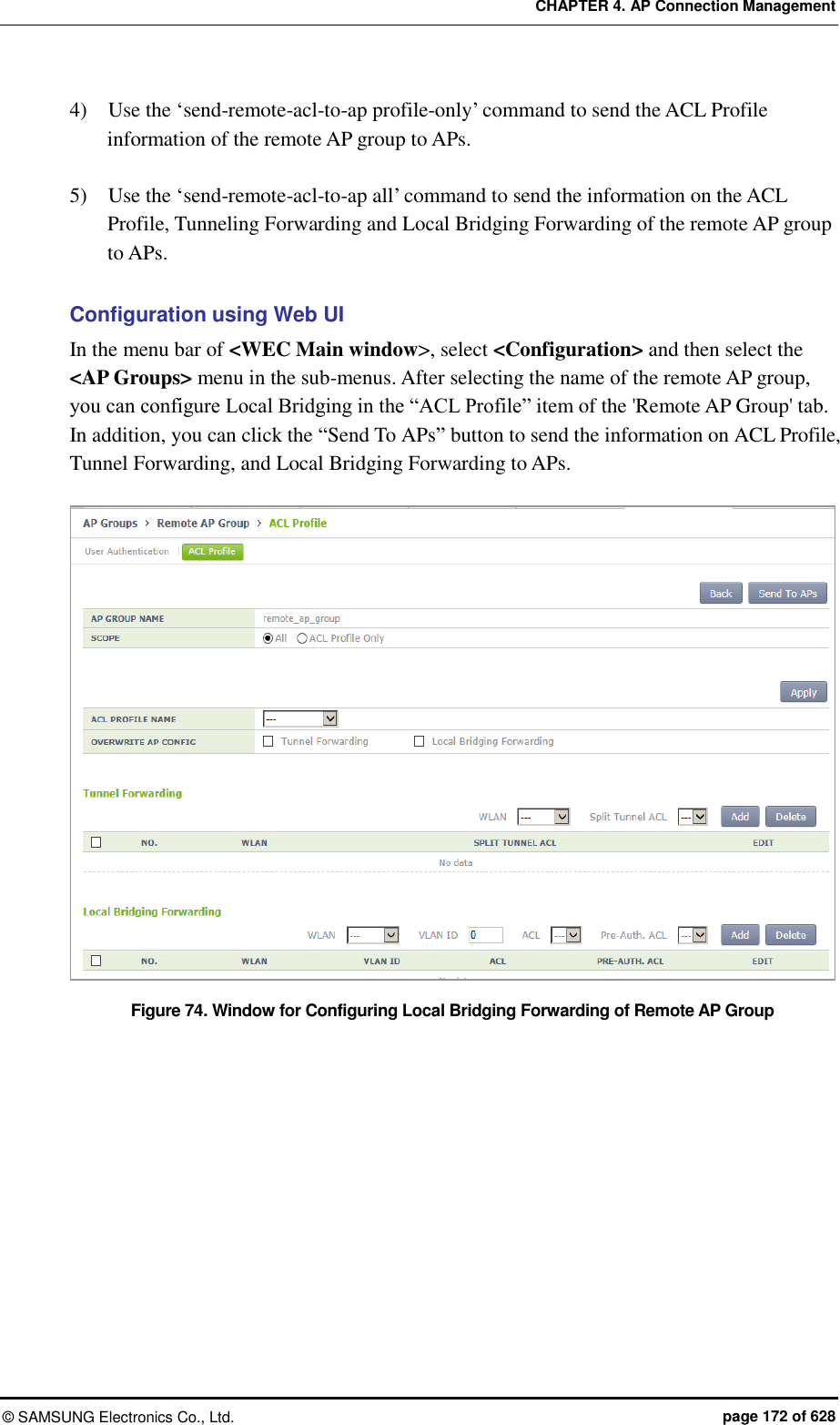
![CHAPTER 4. AP Connection Management © SAMSUNG Electronics Co., Ltd. page 173 of 628 4.2.3 AP Time Synchronization per Group The AP can configure its time information using either the time stamp method or the NTP method. In the Time Stamp type, the APC periodically transmits the time of APC to an AP and the AP is operating based on the received time. Unless a user changes the configuration, the default is Time Stamp type and the interval is set to 7200 seconds (2 hours). In the NTP type, the NTP server information is transmitted to an AP and the AP synchronizes the time with the NTP server. A NTP server list must be created to transmit the NTP server information to an AP and maximum 10 lists can be added. The ntp-interval (2^N) is the interval when an AP receives the time information from the NTP server. For example, if the ntp-interval is set to 6, an AP receives the time information from the NTP server at every 2^6, i.e. 128 seconds. The APC provides a function for configuring the time configuration method of the AP. Configuring Time Stamp type using CLI 1) Go to configure apc ap-time-config configuration mode of CLI. WEC8500# configure terminal WEC8500/configure# apc WEC8500/configure/apc# ap-time-config WEC8500/configure/apc/ap-time-config# 2) Configure how to transmit the time information to an AP using ‘ac-stamp’ and configure the interval. mode ac-stamp ac-stamp-interval [INTERVAL] 3) To check the information, execute the ‘show apc ap-time-config’ command. Configuring NTP type using CLI 1) Go to configure apc ap-time-config configuration mode of CLI. WEC8500# configure terminal WEC8500/configure# apc WEC8500/configure/apc# ap-time-config WEC8500/configure/apc/ap-time-config# 2) Add the NTP server information to transmit to an AP. Maximum 10 NTP server information can be added. To delete the configured NTP server information, enter ‘no’ parameter in front of the command](https://usermanual.wiki/Samsung-Electronics-Co/WEA463E.Part-1/User-Guide-2696662-Page-173.png)
![CHAPTER 4. AP Connection Management © SAMSUNG Electronics Co., Ltd. page 174 of 628 add-ntp [NTP_SERVER_ADDRESS] no add-ntp [NTP_SERVER_ADDRESS] ntp-interval [NUMBER] 3) Configure the method of transmitting the time information to an AP as ‘ntp’. mode ntp 4) Use the ‘show apc ap-time-config’ command to check the configured information. Configuration using Web UI In the menu bar of <WEC Main Window>, select <Configuration>, select <NTP> in the submenu, and then select a time setting mode of the AP (TimeStamp or NTP), timestamp interval, and NTP polling interval. Also, you can add/remove NTP server from which to fetch time access information for the AP. Figure 75. AP Time Synchronization Configuration Options](https://usermanual.wiki/Samsung-Electronics-Co/WEA463E.Part-1/User-Guide-2696662-Page-174.png)
![CHAPTER 4. AP Connection Management © SAMSUNG Electronics Co., Ltd. page 175 of 628 4.2.4 AP Configuration The management interface of APC must be configured for the connection between APC and W-EP AP. 4.2.4.1 Configuring MAC address Configuration using CLI To configure AP information, execute the command as follows: 1) Go to configure AP configuration mode of CLI. WEC8500# configure terminal WEC8500/configure# ap [ap profile name] WEC8500/configure/ap ap_1# If there exists the same AP when entering [ap profile name], you are guided to the mode where operator can configure the AP. If there is no same AP, the new AP information is created. 2) Register the MAC address of the AP. profile mac [MAC_ADDRESS] 3) To check the information of a configured AP, use the ‘show ap summary config’ command. Configuration using Web UI In the menu bar of <WEC Main window>, select <Configuration> and then select the <Access Points> menu in the sub-menus. 1) Click the <Add> button. 2) Set AP PROFILE NAME and MAC ADDRESS and click the <Apply> button. Figure 76. Adding Access Points](https://usermanual.wiki/Samsung-Electronics-Co/WEA463E.Part-1/User-Guide-2696662-Page-175.png)
![CHAPTER 4. AP Connection Management © SAMSUNG Electronics Co., Ltd. page 176 of 628 4.2.4.2 Configuring AP Profile Configuration using CLI To configure an AP profile configuration, execute the command as follows: 1) Go to configure AP configuration AP profile mode of CLI. WEC8500# configure terminal WEC8500/configure# ap ap_1 WEC8500/configure/ap ap_1# profile WEC8500/configure/ap ap_1/profile# 2) Configure the profile of an AP using the below command. name [STRING]: Configures the name of an AP. If it is not entered, the ‘AP_’ + ‘MAC address’ is used as a name. E.g. MAC address: f4:d9:fb:24:cb:a0 AP name: AP_f4d9fb24cba0 ap-mode [generalAp/rootAp/repeaterAp/snifferAp]: Configures the AP operation mode. ap-stats-history-enable: Configures whether to enable the AP statistics history. client-ip [IP_ADDRESS]: Configures the client IP address, if the AP operation mode is set to Sniffer AP. console-enable: This configures whether to allow console access to the AP. discovery [ap-followed/apc-referal/multicast/broadcast/DHCP]: Configures the discovery type of an AP to find APC. ap-followed: Finds the APC using the discovery type and discovery list configured in an AP. apc-referal: Uses the APC list information configured in an APC as the discovery list DHCP: Uses the APC list information that is received through DHCP option 138 (IPv4) or option 52 (IPv6) as the discovery list. auto: Discovery type is automatically changed by the AP for automatic connection to the APC. discovery-interval [INTERVAL]: Configures the time waiting for a CAPWAP discovery response message (unit: seconds) dtls-policy: Configures the DTLS Policy of an AP. echo-interval [INTERVAL]: Configures the time when an AP transmits an echo request to the joined APC (Unit: seconds) echo-retransmit-interval [INTERVAL]: Waiting time to retransmit an echo request message if there is no reply. The APC configures the echo timeout as much as two times of echo-interval. If the APC cannot receive an echo message from an AP until two times of echo-interval is elapsed, the APC assumes that the AP is down (Unit: seconds)](https://usermanual.wiki/Samsung-Electronics-Co/WEA463E.Part-1/User-Guide-2696662-Page-176.png)
![CHAPTER 4. AP Connection Management © SAMSUNG Electronics Co., Ltd. page 177 of 628 edge-ap: Configures whether to enable the Edge AP function. edge-ap-opmode: Smart Handover is enabled as operation mode of the edge AP. In RSSI mode, handover is determined by looking up the RSSI value. In Force mode, handover is performed by force. edge-ap-threshold: Configures a threshold value for performing smart handover at the edge AP (range: -60 to -100 dBm, default: -80 dBm). edge-ap-window: Configures a window value for performing smart handover at the edge AP (range: 200-1000 ms, default: 200 ms). fragment-size [SIZE]: Configures a fragment size based on MTU to prevent the fragmentation of a CAPWAP packet that is transmitted by an AP to the APC. ip-mode [dhcp/static/ap]: Configures the IP address of an AP to DHCP, Static or AP Followed. dhcp: Configures the AP IP operation type to DHCP static: Configures the AP IP operation type to static ap: Operates with an IP configured in an AP led-config: Configures LED on/off setting of the AP. on: Sets LED of the AP on. off: Sets LED of the AP off. off-time: Sets LED of the AP off only for specific hours. local-bridging: Configures WLAN-VLAN Mapping of the Local Switching WLAN, ACL, and Pre-Authentication ACL of Captive Portal for each remote AP. vlan-id: Configures a VLAN ID to allocate to the Local Switching WLAN. acl-name: Configures an ACL name to allocate to the Local Switching WLAN for packet allowance/blocking. pre-auth-name: Configures a Pre-Authentication ACL name for Captive Portal operation of the Local Switching WLAN. location [STRING]: Configures the information of location where an AP is installed. mac [MAC_ADDRESS]: Configures the MAC address of an AP max-echo-retransmit [COUNT]: Configures the maximum number of retransmission times of an echo request message. max-retransmit [COUNT]: Configures the maximum number of retransmission times of a CAPWAP control message. name [STRING]: Configures an AP name. native-vlanId [VLAN_ID]: Configures the native VLAN in an AP. primary-apc [APC_AME]: Configures the name of a primary APC. secondary-apc [APC_AME]: Configures the name of a secondary APC. tertiary-apc [APC_AME]: Configures the name of a tertiary APC. The WEC8050 model does not support the tertiary-apc function. repeater-whitelist [MAC ADDRESS]: Adds the Repeater AP Whitelist. report-interval [INTERVAL]: Configures the time interval for an AP to transmit the description error to the APC (Unit: seconds) retransmit-interval [INTERVAL]: Configures the waiting time until the AP retransmits a CAPWAP control message when there is no reply from the APC (unit: seconds)](https://usermanual.wiki/Samsung-Electronics-Co/WEA463E.Part-1/User-Guide-2696662-Page-177.png)
![CHAPTER 4. AP Connection Management © SAMSUNG Electronics Co., Ltd. page 178 of 628 ssh-enable: Configures whether to enable the SSH server of an AP. static-ip [IP_ADDRESS] [NETMASK] [GATEWAY]: Configures the static IP address of an AP. statistics-timer [TIMER]: Configures the time interval of transmitting the statistics information provided by CAPWAP (unit: seconds) telnet-enable: Configures whether to enable the telnet server of an AP. time-config: Configure the timezone per AP. vlan-support: Configures whether to enable the native VLAN of an AP. poe-type: Set the POE Type of the AP. You can set 802.3at, 802.3af, and auto. uplink-bandwidth: Set the allowed value for AP uplink bandwidth. Possible to set between 1 and 1024 Mbps and if it is set to 0, the uplink bandwidth is not restricted. temperature-alarm-on-level: If the temperature of the AP exceeds the Temperature-Alarm-On-Level, the temperature alarm occurs. The default is 98 and possible to set between 50 and 130. temperature-alarm-off-level: If the temperature of the AP is less than the Temperature-Alarm-Off-Level, the temperature alarm is cleared. The default is 98 and possible to set between 50 and 130. temperature-alarm-control-type: If the temperature alarm occurs, set whether the radio of the AP is set to be off or on. link-aggregation: In case of an AP model for 802.11ac, provide two uplink Ethernet ports. Possible to set link aggregation for two Ethernet ports. If the link aggregation is activated, Both (Destination + Source), Destination, and Source modes are configurable. OVERWRITE-UPLINK-BANDWIDTH If the overwrite-uplink-bandwidth is activated, the uplink bandwidth information set in the AP group is applied to all APs in the group. UPLINK-BANDWIDTH Set the allowed value for AP uplink bandwidth. Possible to set between 1 and 1024 Mbps and if it is set to 0, the uplink bandwidth is not restricted. OVERWRITE-TEMPERATURE-ALARM If the overwrite-temperature-alarm is activated, the temperature alarm information set in the AP group is applied to all APs in the group. TEMPERATURE-ALARM-ON-LEVEL If the temperature of the AP exceeds the Temperature-Alarm-On-Level, the temperature alarm occurs. The default is 98 and possible to set between 50 and 130. TEMPERATURE-ALARM-OFF-LEVEL If the temperature of the AP is less than the Temperature-Alarm-Off-Level, the temperature alarm is cleared. The default is 90 and possible to set between 50 and 130. TEMPERATURE-ALARM-CONTROL-TYPE If the temperature alarm occurs, set whether the radio of the AP is set to be off or on. OVERWRITE-LINK-AGGREGATION If the overwrite-link-aggregation is activated, the link aggregation information set in the AP group is applied to all APs in the group. LINK-AGGREGATION In case of an AP model for 802.11ac, provide two uplink](https://usermanual.wiki/Samsung-Electronics-Co/WEA463E.Part-1/User-Guide-2696662-Page-178.png)
![CHAPTER 4. AP Connection Management © SAMSUNG Electronics Co., Ltd. page 179 of 628 Ethernet ports. Possible to set link aggregation for two Ethernet ports. If link aggregation is activated, possible to set the following mode: - Both (Destination + Source) - Destination - Source 3) To check the information of a configured AP profile, use the ‘show ap detail [AP_NAME]’ command. Configuration using Web UI In the menu bar of <WEC Main window>, select <Configuration> and then select the <Access Points> AP selection <General> menu in the sub-menus. The setting options in the General tab are as follows. Click the <Apply> button to apply the settings. Figure 77. AP Profile Setting (1) AP NAME: AP name AP GROUP NAME: Indicates name of the AP GROUP to which the AP belongs. REMOTE AP GROUP NAME: Indicates name of the REMOTE AP GROUP to which the AP belongs. AP MODE: AP operational mode (General AP/Root AP/Repeater AP/Sniffer AP) MAC ADDRESS: Cannot be changed to the MAC address of an AP.](https://usermanual.wiki/Samsung-Electronics-Co/WEA463E.Part-1/User-Guide-2696662-Page-179.png)
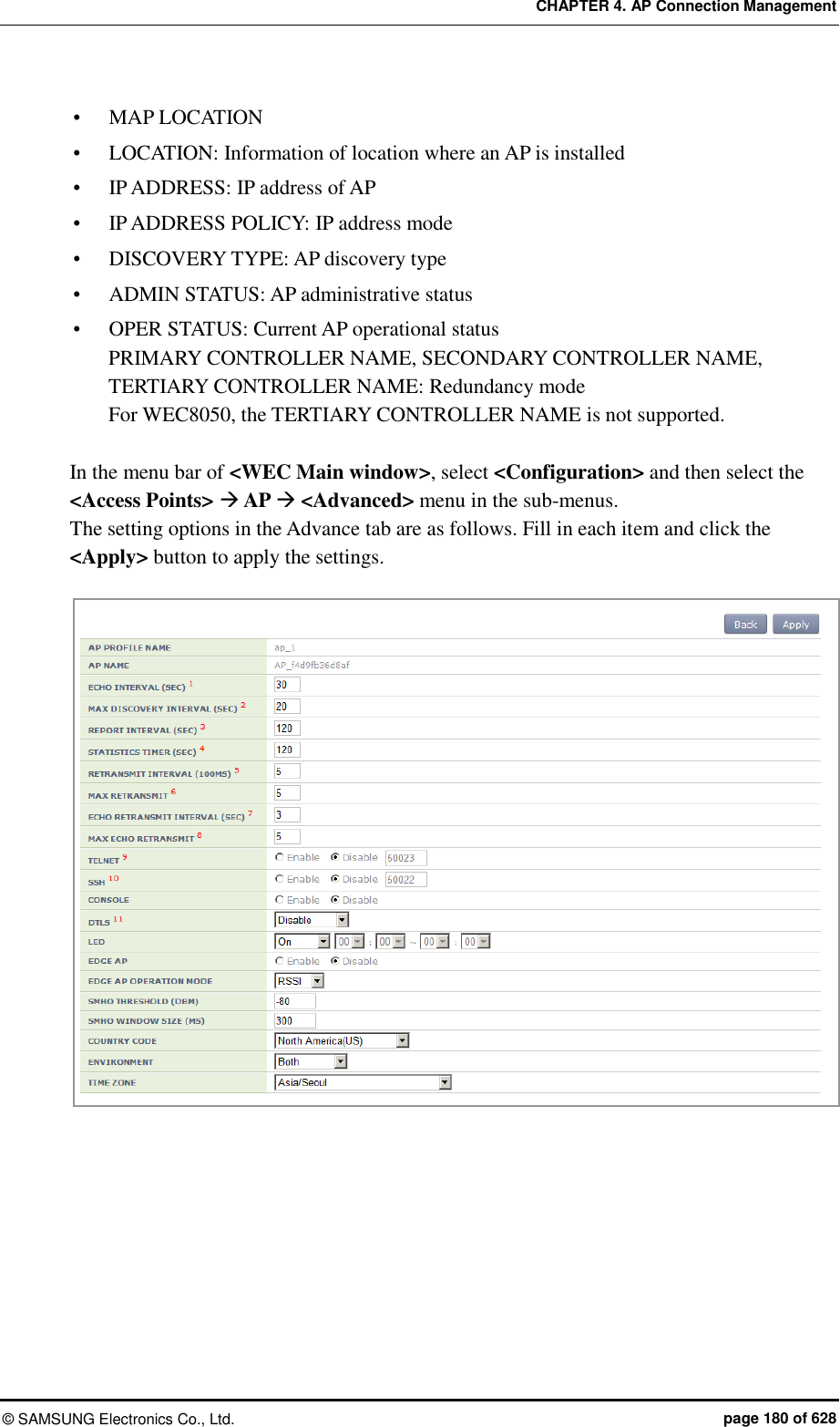
![CHAPTER 4. AP Connection Management © SAMSUNG Electronics Co., Ltd. page 181 of 628 Figure 78. AP Profile Setting (2) 4.2.4.3 AP Mode Configuration Configuration using CLI To configure AP mode, execute the command as follows. 1) Go to configure AP configuration AP profile mode of CLI. WEC8500# configure terminal WEC8500/configure# ap ap_1 WEC8500/configure/ap ap_1# profile WEC8500/configure/ap ap_1/profile# 2) Configure the AP mode. ap-mode [MODE] Parameter Description MODE AP operation mode (generalAp/rootAp/repeaterAp/snifferAp) - generalAp: Typical operation mode. Default value. - rootAp: AP mode where a repeater AP can be connected. - repeasterAp: AP mode that is connected to a wireless area and the APC through the root AP. - snifferAp: AP mode where the packets operating in a wireless environment can be captured. - relayAp: An AP mode which connects a root AP and a repeater AP wirelessly 3) To check the information of a configured AP, use the ‘show ap detail [AP_NAME]’ command.](https://usermanual.wiki/Samsung-Electronics-Co/WEA463E.Part-1/User-Guide-2696662-Page-181.png)
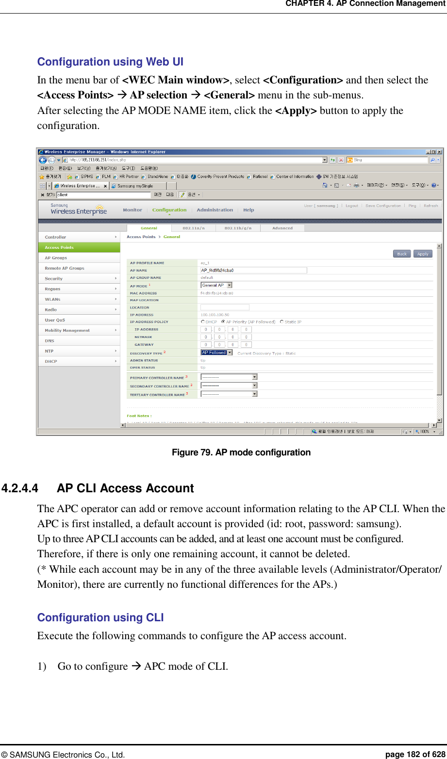
![CHAPTER 4. AP Connection Management © SAMSUNG Electronics Co., Ltd. page 183 of 628 WEC8500# configure terminal WEC8500/configure# apc WEC8500/configure/apc # 2) Add an AP CLI account. ap-account [ID] [PASSWORD] [LEVEL] Parameter Description ID This is the ID of the AP CLI account. Only an alphanumeric value of up to eight characters can be entered. Password This is the password of the AP CLI account. Only an alphanumeric value of up to eight characters can be entered. Level This is the level of the AP CLI account. Available values are administrator/operator/monitor. 3) An account can be deleted by entering the 'no' parameter as shown below. no ap-account [ID] 4) Use the ‘show apc ap-account’ command to retrieve the AP configuration information. Configuration using Web UI In the menu bar of <WEC Main Window>, select <Configuration>, and then select <Local Management Users> AP in the submenu. Click the ‘Add’ or ‘Delete’ button to add or delete the AP CLI account. Figure 80. AP CLI Account Add/Remove Window](https://usermanual.wiki/Samsung-Electronics-Co/WEA463E.Part-1/User-Guide-2696662-Page-183.png)
![CHAPTER 4. AP Connection Management © SAMSUNG Electronics Co., Ltd. page 184 of 628 4.2.4.5 AP SNMP Agent Configuration The APC operator can configure SNMP Agent settings for all APs. Configuration using CLI Execute the following commands to configure the SNMP Agent settings of the AP. 1) Go to configure snmp ap mode of CLI. WEC8500# configure terminal WEC8500/configure# snmp WEC8500/configure/snmp# ap WEC8500/configure/snmp/ap# 2) Configure the snap agent information of the AP. Enable/disable SNMP of the AP. enable or no enable Configure the SNMP port number of the AP. Port [PORT NUMBER] Configure the Read Only Community Name of the AP. ro-community [COMMUNITY NAME] Configure the Write Only Community Name of the AP. rw-community [COMMUNITY NAME] Configure the user information of the AP. Use r[USER NAME] [AUTHENTICATION TYPE] [AUTHENTICATION KEY] [PRIVATE PROTOCOL] [PRIVATE KEY] Parameter Description PORT NUMBER This is the SNMP port number. COMMUNITY NAME This is the SNMP Read Only or Write Only Community name. USER NAME This is the SNMP user name. AUTHENTICATION TYPE This is the SNMP authentication type. Either of the following two can be selected: - MD5 - SHA AUTHENTICATION KEY A number in the range of 8 to 20 can be entered. PRIVATE PROTOCOL Either of the following two can be selected: - DES - AES](https://usermanual.wiki/Samsung-Electronics-Co/WEA463E.Part-1/User-Guide-2696662-Page-184.png)
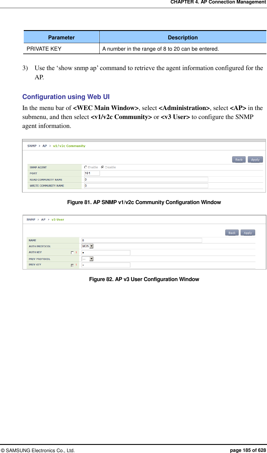
![CHAPTER 4. AP Connection Management © SAMSUNG Electronics Co., Ltd. page 187 of 628 4.2.5.2 Real-time Interface Statistics Information Configuration using CLI 1) Go to configure AP configuration. WEC8500# configure terminal WEC8500/configure# ap ap_1 WEC8500/configure/ap ap_1# 2) Configure to make real-time interface statistics information updated periodically. WEC8500/configure/ap ap_1# get-if-stats 3) To check the interface statistics information of an AP, use the ‘show ap if-stats [AP_NAME]’ command. Configuration using Web UI In the menu bar of <WEC Main window>, select <Monitor> and then select the <Statistics> <AP Ports> menu in the sub-menus. As shown below, you can retrieve the real-time interface statistics of the AP. Select an item in the list, and then you can check detail information. Figure 83. AP Ports window Figure 84. AP Ports detail information window](https://usermanual.wiki/Samsung-Electronics-Co/WEA463E.Part-1/User-Guide-2696662-Page-187.png)
![CHAPTER 4. AP Connection Management © SAMSUNG Electronics Co., Ltd. page 188 of 628 4.2.5.3 Tech Support Information Execute the below command to download the Tech Support information from an AP. Configuration using CLI 1) Go to configure AP configuration tech-support of CLI. WEC8500# configure terminal WEC8500/configure# ap [ap profile name] WEC8500/configure/ap ap_1# tech-support WEC8500/configure/ap ap_1/tech-support# 2) Request the coredump file of the AP. WEC8500/configure/ap ap_1/tech-support# get-coredump (system / radio-coredump) 3) Request the crashfile of the AP. WEC8500/configure/ap ap_1/tech-support# get-crash-file (system / radio-coredump) 4) Request the log file of the AP. WEC8500/configure/ap ap_1/tech-support# get-log-file 5) Use ‘show ap tech-support’ command to check the Tech Support file information of APs. Operator can use FTP or sFTP to download Tech Support files. Configuration using Web UI In the menu bar of <WEC Main window>, select <Administrator> and then select the <Tech Support> <AP Crash> menu in the sub-menus. By clicking the profile name of an AP, operator can download the Tech Support file. Figure 85. AP Tech Support Information Receiving Window](https://usermanual.wiki/Samsung-Electronics-Co/WEA463E.Part-1/User-Guide-2696662-Page-188.png)
![CHAPTER 4. AP Connection Management © SAMSUNG Electronics Co., Ltd. page 189 of 628 4.2.6 Outdoor AP Configuration The APC system provides outdoor AP connection diagnostic functions for outdoor APs. The AP connection diagnostics function checks ping status of outdoor APs and displays the results on the operator’s monitor. Procedure of using the outdoor AP connection diagnostics function is as follows: 1) The operator creates/deletes outdoor APWEC using CLI. 2) The APC system periodically pings the outdoor AP to check the network connection of the AP and stores the results. 3) The operator uses the WEC, WEM or CLI to determine network connection status of the outdoor AP. Concerning outdoor AP count: 1) Outdoor APs are not included in the AP count of the APC license. 2) Outdoor APs are not included in the ordinary AP count. 3) The maximum up-ported outdoor AP count is 300 for the WEC8500 model and 75 for the WEC8050 model. 4) The APC system can retrieve the total/up/down outdoor AP count using the WEC or CLI. 4.2.6.1 Outdoor AP Addition/Removal The APC system allows creation/deletion of outdoor AP information using the WEC or CLI. Configuration using CLI 1) Go to configure mode of CLI. WEC8500# configure terminal WEC8500/configure# 2) Create or delete an AP. Use the ‘no’ parameter in front of the command to delete an outdoor AP. outdoor-ap [PROFILE_NAME] [MAC_ADDRESS] [IP_ADDRESS] no outdoor-ap [PROFILE_NAME] 3) Create or delete an outdoor AP. Use the ‘no’ parameter in front of the command to delete an outdoor AP. 4) Use the ‘show ap summary’ command to check the outdoor AP information.](https://usermanual.wiki/Samsung-Electronics-Co/WEA463E.Part-1/User-Guide-2696662-Page-189.png)
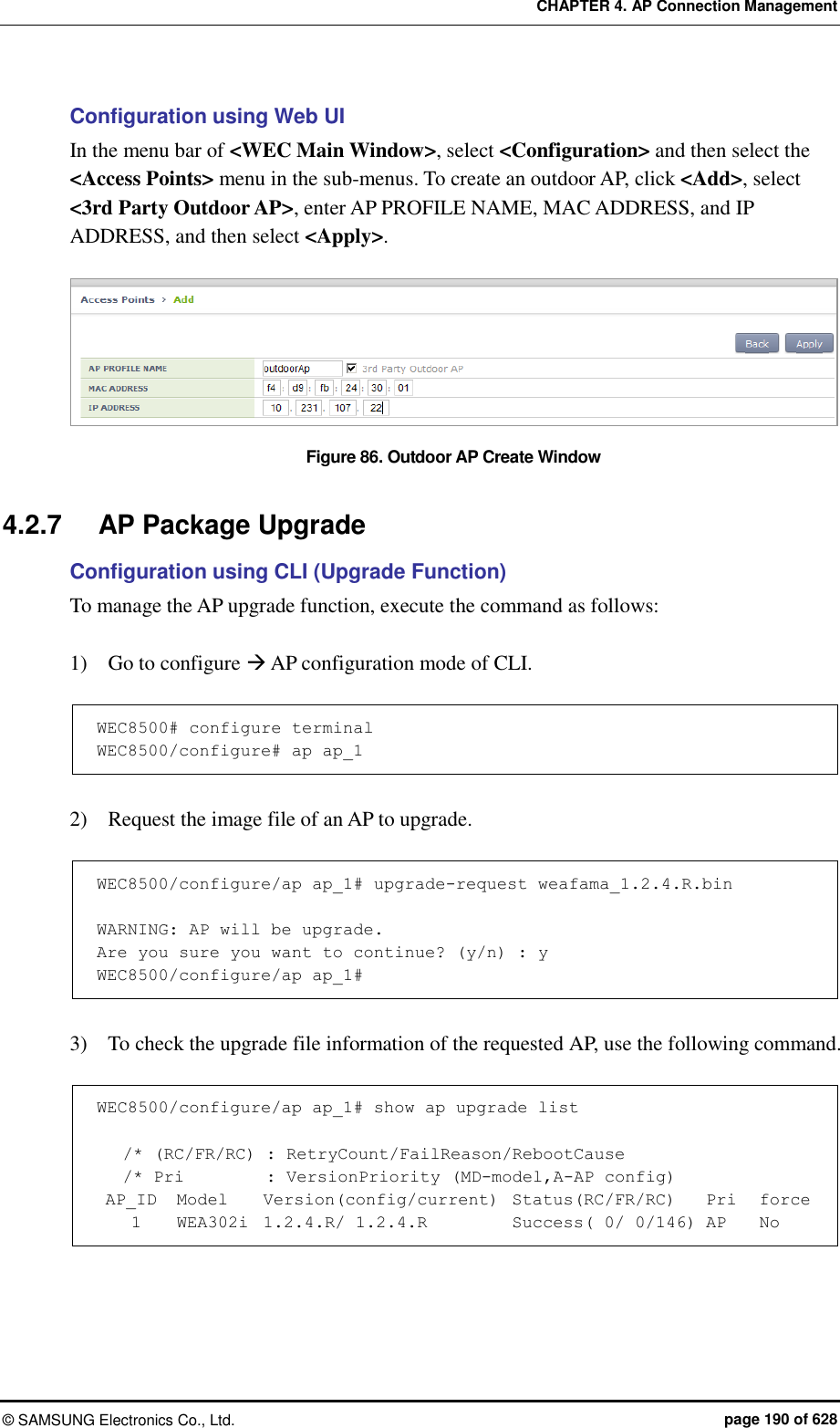
![CHAPTER 4. AP Connection Management © SAMSUNG Electronics Co., Ltd. page 191 of 628 Configuration using CLI (Upgrade environment) To configure AP upgrade related environment, the following command is provided. First of all, go to the configure AP-all upgrade mode of CLI. WEC8500# configure terminal WEC8500/configure# ap-all WEC8500/configure/ap-all# upgrade WEC8500/configure/ap-all/upgrade# [select-package] This command configures a package to use during AP upgrade. select-package [UPGRADE_TYPE] [FILE_NAME] Parameter Description UPGRADE_TYPE Configures upgrade type (default/quick-upgrade/predownload) - default: AP image that is referred to during provision upgrade. - quick-upgrade: AP image that is referred to for entire AP upgrade upon an operator’s request. - predownload: AP image that is referred to download AP image to AP during entire AP upgrade. FILE_NAME Image file name that will be used for AP upgrade [target] During entire upgrade, you can select whether to maintain individual configured AP version of an AP or perform upgrade. Target [AP UPGRADE TARGET] Parameter Description UPGRADE TARGET Upgrade target (all/ keeping-individual) - all: Perform upgrade for all the APs. (default) - keeping-individual: While maintaining individually configured ap version, perform upgrade for the rest APs. [transfer-protocol] This command selects a transmission protocol that is used to transmit the package file of an AP from the WEC8500 to the AP. Transfer-protocol [AP TRANSFER MODE] Parameter Description TRANSFER_MODE File transmission protocol (ftp/sftp) - ftp: ftp is used for file transmission. - sftp: sftp is used for file transmission.](https://usermanual.wiki/Samsung-Electronics-Co/WEA463E.Part-1/User-Guide-2696662-Page-191.png)
![CHAPTER 4. AP Connection Management © SAMSUNG Electronics Co., Ltd. page 192 of 628 [max-download] This command configures the maximum number of simultaneous downloads when transmitting the package file of an AP from the APC to the AP. Max-download [COUNT] Parameter Description COUNT Maximum number of simultaneous downloads of AP image file (range: 1-50, default: 10) [max-retry] This command configures maximum number of re-attempts when AP upgrade is failed. Max-retry [COUNT] Parameter Description COUNT Maximum number of AP upgrade re-attempts (range: 1-10, default: 3) [start] This command provides the entire AP upgrade function. start [UPGRADE_TYPE] Parameter Description UPGRADE_TYPE Configures upgrade type (quick-upgrade/predownload) - quick-upgrade: Perform entire ap upgrade upon an operator’s request. - predownload: Download ap image to ap first during entire ap upgrade. If you perform package upgrade after configuring AP upgrade type to predownload, restart all the APs in the following methods. WEC8500# configure terminal WEC8500/configure# ap-all WEC8500/configure/ap-all# reboot upgrade [stop] This command provides the function of stopping the image upgrade of all the APs. stop [show ap upgrade] To check the upgrade information of an AP, use the following command. show ap upgrade summary](https://usermanual.wiki/Samsung-Electronics-Co/WEA463E.Part-1/User-Guide-2696662-Page-192.png)
![CHAPTER 4. AP Connection Management © SAMSUNG Electronics Co., Ltd. page 193 of 628 Configuration using Web UI In the menu bar of <WEC Main window>, select <Administrator> and then select <Package Upgrade> <AP> menu in the sub menu. You can perform AP upgrade in the AP Upgrade tab and configure upgrade related environment in the Advanced tab. [AP Upgrade tab] AP Upgrade tab upgrades all the APs or a specific AP. Figure 87. AP upgrade The procedure of entire AP upgrade is as follows: 1) In the AP Upgrade window, click the <Global> button. 2) The <Global> area is displayed on the window. After configuring each item, click the <Apply> button. Figure 88. AP upgrade-global](https://usermanual.wiki/Samsung-Electronics-Co/WEA463E.Part-1/User-Guide-2696662-Page-193.png)
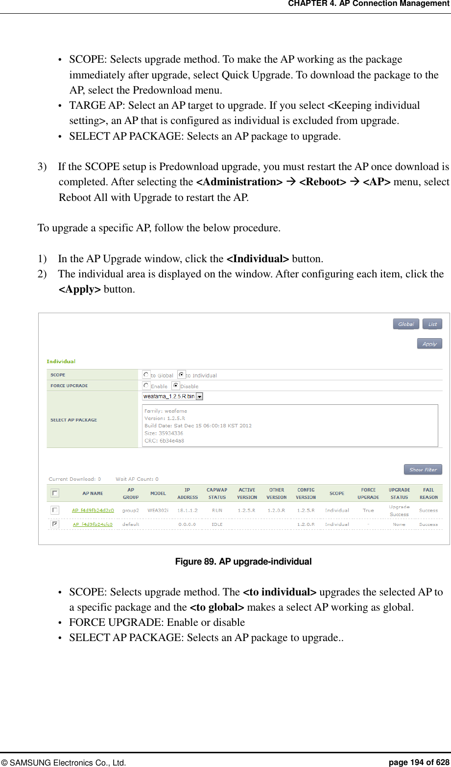
![CHAPTER 4. AP Connection Management © SAMSUNG Electronics Co., Ltd. page 195 of 628 [Advanced tab] Configures AP upgrade related environment settings. Figure 90. AP upgrade-advanced TRANSFER MODE: Selects a protocol that transmits an AP package. MAX DOWNLOAD: Configures maximum number of sessions that can be downloaded simultaneously. MAX RETRY: Configures maximum number of re-attempts when AP upgrade is failed. DEFAULT AP PACKAGE: Select an AP package that will be used for automatic upgrade during AP joint. 4.2.8 Remote AP Package Upgrade APs in a remote group can be upgraded by downloading an AP package from a specific AP. This is useful for efficient management of APC-AP bandwidth. A master AP can be selected for each AP package model. After downloading an AP package from the APC, the master AP allows the AP package to be downloaded to other APs in the remote group. The operator can manage AP upgrade of the APs in the remote group by checking the AP package download status in the remote group and performing reboot and upgrade. 4.2.8.1 Activating Upgrade The operator can enable/disable the AP upgrade in the remote group. When the AP upgrade is enabled, version priority in AP upgrade status changes to Remote. Configuration using CLI Example: WEC8500# configure terminal WEC8500/configure# ap-group rUpgrade WEC8500/configure/ap-group rUpgrade# remote WEC8500/configure/ap-group rUpgrade/remote# upgrade WEC8500/configure/ap-group rUpgrade/remote/upgrade# enable WEC8500/configure/ap-group rUpgrade/remote/upgrade# no enable](https://usermanual.wiki/Samsung-Electronics-Co/WEA463E.Part-1/User-Guide-2696662-Page-195.png)
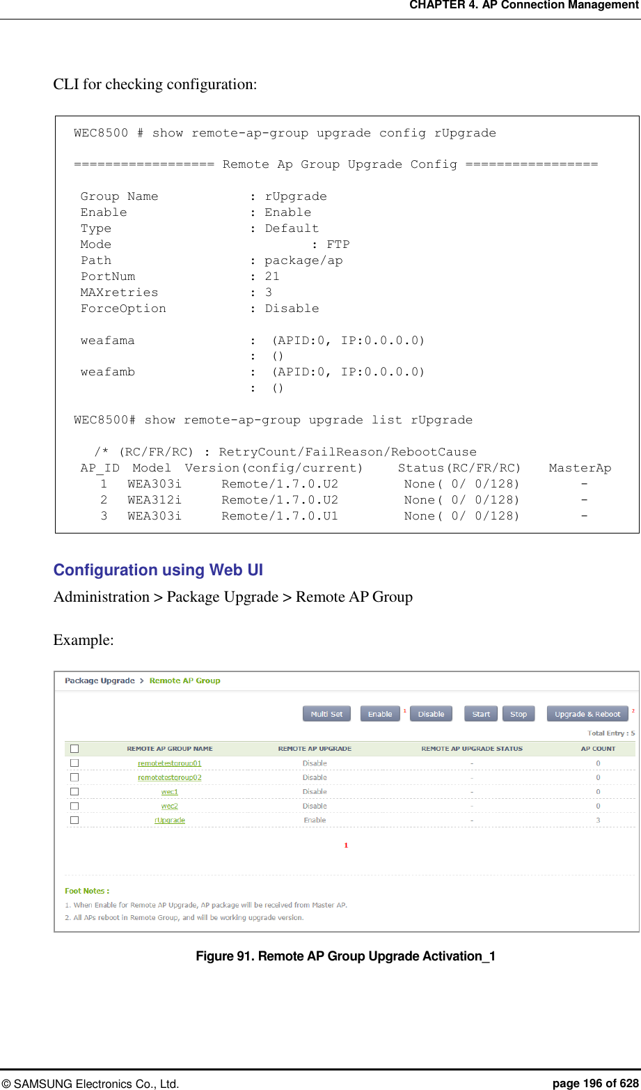
![CHAPTER 4. AP Connection Management © SAMSUNG Electronics Co., Ltd. page 197 of 628 Figure 92. Remote AP Group Upgrade Activation_2 4.2.8.2 Master AP Configuration (Optional) The operator can configure the master AP for AP upgrade in the remote group. If none is configured, a master AP is automatically selected. Configuration using CLI Example: WEC8500# configure terminal WEC8500/configure# ap-group rUpgrade WEC8500/configure/ap-group rUpgrade# remote WEC8500/configure/ap-group rUpgrade/remote# upgrade WEC8500/configure/ap-group rUpgrade/remote/upgrade# select-masterAP ap_1 WEC8500/configure/ap-group rUpgrade/remote/upgrade# delete-masterAP [weafama/weafamb] CLI for checking configuration: WEC8500# show remote-ap-group upgrade config rUpgrade ================== Remote Ap Group Upgrade Config ================= Group Name : rUpgrade Enable : Enable Type Default Mode : FTP Path : package/ap PortNum : 21 MAXretries : 3 ForceOption : Disable weafama : ap_1 (APID:1, IP:10.10.10.160) : () weafamb : (APID:0, IP:0.0.0.0) : ()](https://usermanual.wiki/Samsung-Electronics-Co/WEA463E.Part-1/User-Guide-2696662-Page-197.png)
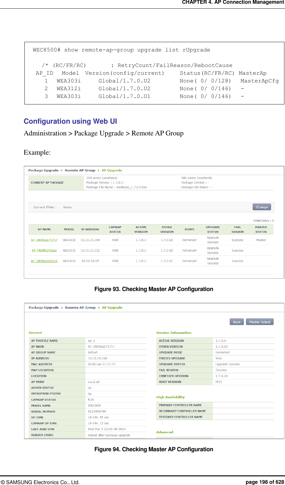
![CHAPTER 4. AP Connection Management © SAMSUNG Electronics Co., Ltd. page 199 of 628 4.2.8.3 AP Package Configuration The operator can configure an AP package to upgrade in the remote group. Configuration using CLI Example: WEC8500# configure terminal WEC8500/configure# ap-group rUpgrade WEC8500/configure/ap-group rUpgrade# remote WEC8500/configure/ap-group rUpgrade/remote# upgrade WEC8500/configure/ap-group rUpgrade/remote/upgrade# select-package weafama weafama_1.7.0.U.bin WEC8500/configure/ap-group rUpgrade/remote/upgrade#delete-package [weafama/weafamb] CLI for checking configuration: WEC8500# show remote-ap-group upgrade config rUpgrade ================== Remote Ap Group Upgrade Config ================= Group Name : rUpgrade Enable : Enable Type : Default Mode : FTP Path : package/ap PortNum : 21 MAXretries : 3 ForceOption : Disable weafama : ap_1 (APID:1, IP:10.10.10.160) : weafama_1.7.0.U.bin (1.7.0.U) weafamb : (APID:0, IP:0.0.0.0) : ()](https://usermanual.wiki/Samsung-Electronics-Co/WEA463E.Part-1/User-Guide-2696662-Page-199.png)
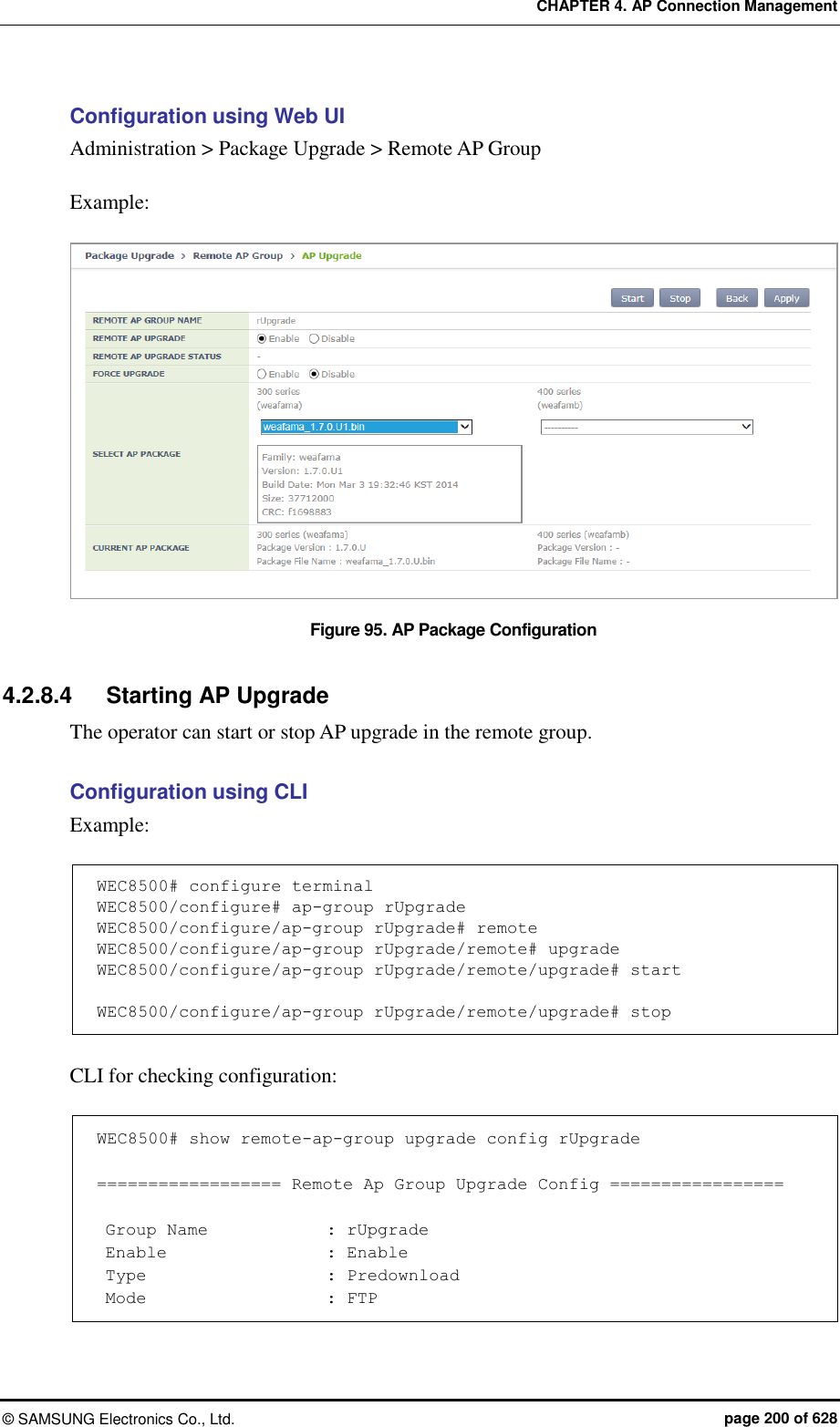
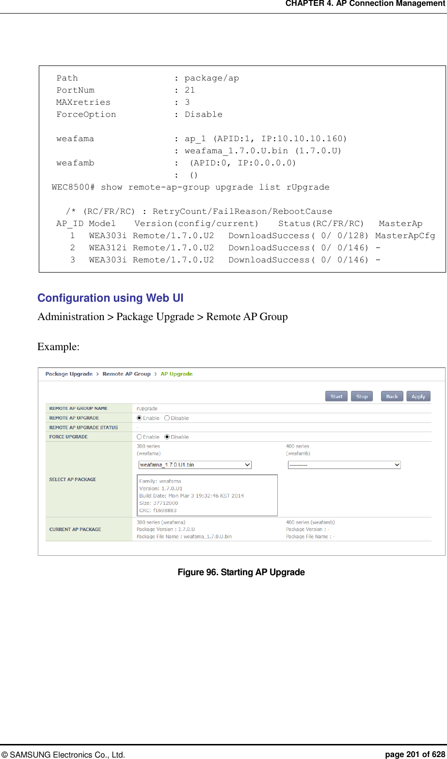
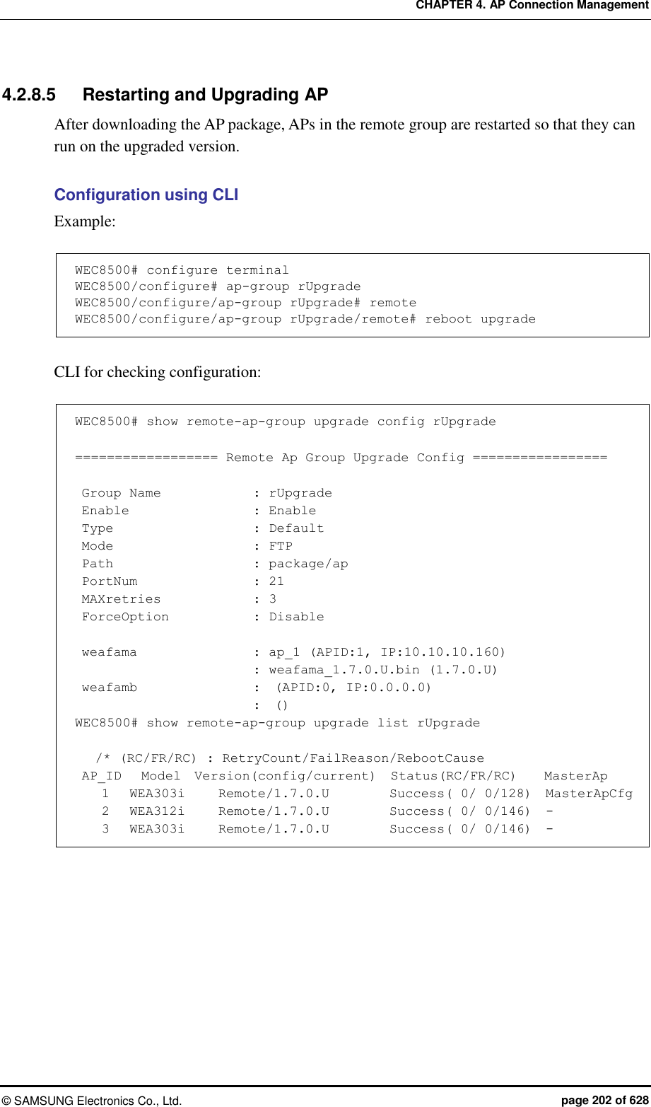
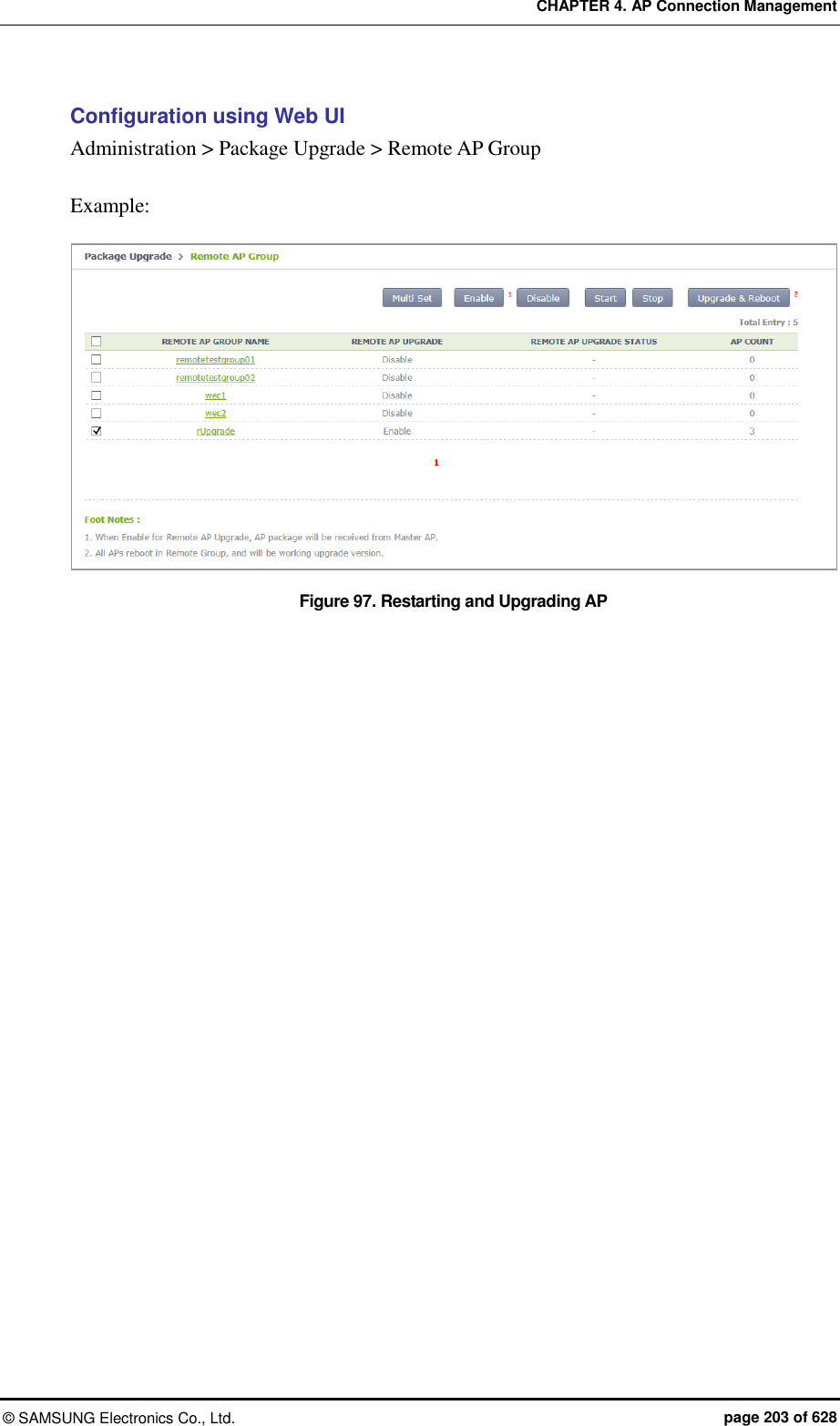
![CHAPTER 5. WLAN Management © SAMSUNG Electronics Co., Ltd. page 204 of 628 CHAPTER 5. WLAN Management This chapter describes how to create and configure WLAN that is the most fundamental basis for W-EP wireless LAN service. 5.1 WLAN Configuration 5.1.1 Basic WLAN Configuration The WLAN profile helps configure and manage the WLAN connection service of an AP in the APC. To use WLAN service, it is necessary to basically configure AP group and interface group and specify Service Set Identifier (SSID). Configuration using CLI Go to the wlan configuration mode from the configure mode of CLI. WEC8500# configure terminal WEC8500/configure# wlan [WLAN ID] Parameter Description WLAN_ID WLAN ID (range: 1-255) The WLAN configuration procedures are as follows: 1) Go to configure wlan configuration mode of CLI. WEC8500# configure terminal WEC8500/configure# wlan 1 WEC8500/configure/wlan 1# 2) Add WLAN to an AP group. Configure an AP group to which WLAN service will be provided. The AP group configuration is only possible in the AP group configuration mode instead of the wlan configuration mode. The below configuration allocates wlan 1 to the apg_01 AP group.](https://usermanual.wiki/Samsung-Electronics-Co/WEA463E.Part-1/User-Guide-2696662-Page-204.png)
![CHAPTER 5. WLAN Management © SAMSUNG Electronics Co., Ltd. page 205 of 628 A newly created WLAN is added to the ‘default’ AP group if the WLAN ID is in the range of 1-16. If its WLAN ID is 17 or above, the WLAN is not included in the AP group. Maximum 16 WLANs can be allocated to each AP group. WEC8500# configure terminal WEC8500/configure# ap-group apg_01 WEC8500/configure/ap-group apg_01# add-wlan 1 3) Configure an interface group to which the WLAN service will be provided. Several VLAN interfaces can be added to an interface group, and the WLAN service is available only through the interface. if-group [INTERFACE_GROUP_NAME] 4) Configure a SSID. The SSID is an ID used to connect to each wireless terminal to provide the WLAN service. Make sure to configure a SSID to use the WLAN service. ssid [SSID_NAME] 5) Configure radio by selecting 2.4G, 5G or All (2.4G/5G). radio [Radio ID: 1: 5 GHz, 2: 2.4 GHz, 3: ALL] 6) Configure whether to apply the WLAN service. WEC8500/configure/wlan 1#enable To apply the various WLAN services to multiple wireless terminals, create the WLAN service in a profile format. Once the WLAN service is started, make each AP use the WLAN service by downloading the profile.](https://usermanual.wiki/Samsung-Electronics-Co/WEA463E.Part-1/User-Guide-2696662-Page-205.png)
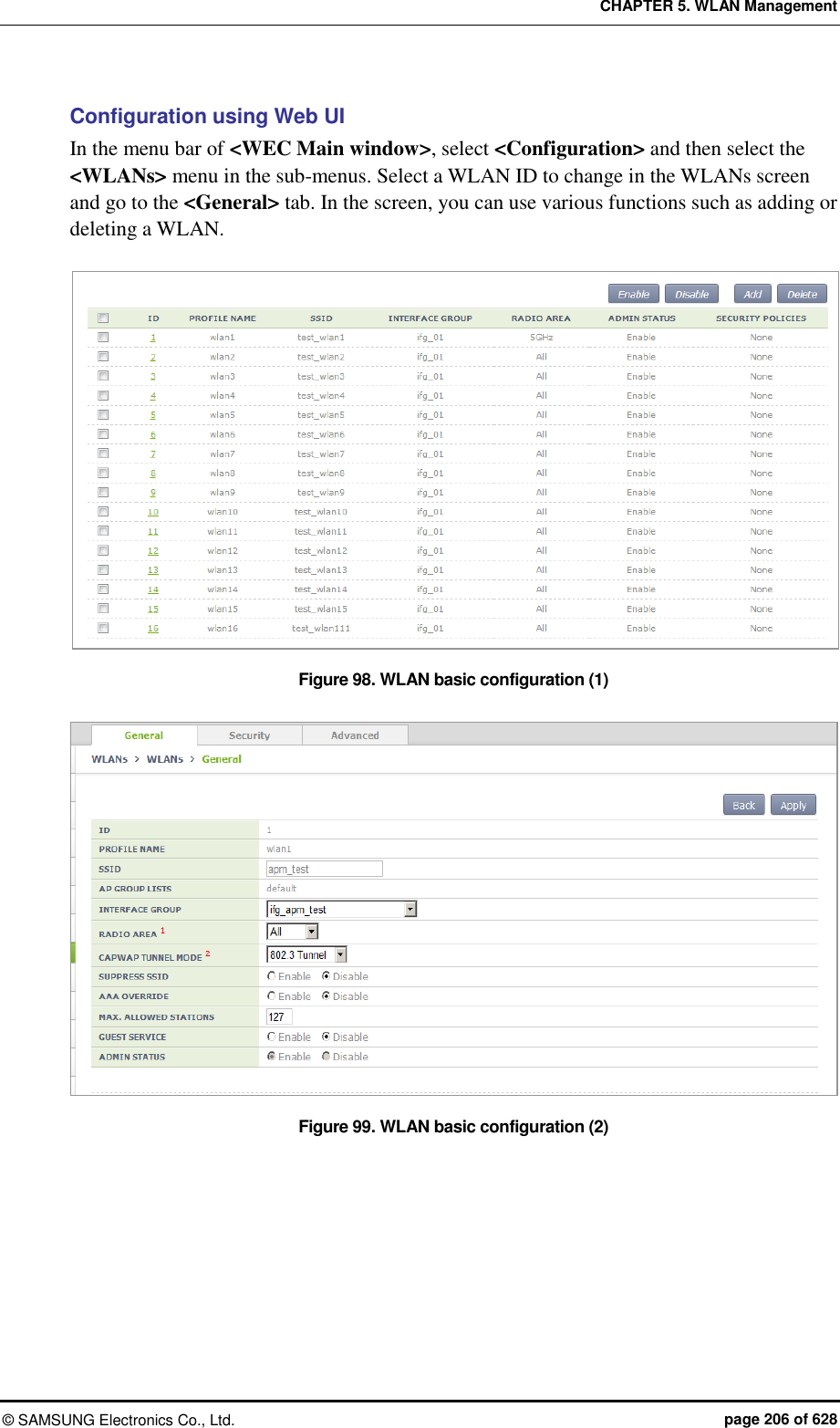
![CHAPTER 5. WLAN Management © SAMSUNG Electronics Co., Ltd. page 207 of 628 You can configure various functions such as interface group and SSID, etc. The configurations available in the General tab are as follows: INTERFACE GROUP: Configures an interface group. RADIO AREA: Configures a radio area. CAPWAP TUNNEL MODE/LOCAL VLAN: Configures the local switching function. SUPRESS SSID: Enables or disables the function. AAA OVERRIDE: If the WLAN is enabled with the device authentication function using a AAA server, the AAA-override function can be enabled so that the user-specific settings configured in the AAA server are applied with priority over the APC settings. MAXIMUM ALLOWED STATIONS: Limits the number of users per WLAN. GUEST SERVICE: Enables or disables the Guest service. ADMIN STATUS: Enables or disables the function. 5.1.2 WLAN Additional Configuration Each wireless terminal can receive a differentiated service according to the WLAN configuration. The procedure of configuring the WLAN additional function is as follows. Configuration using CLI 1) Go to configure wlan configuration mode of CLI. WEC8500# configure terminal WEC8500/configure# wlan 1 WEC8500/configure/wlan 1 2) If the WLAN is enabled with the device authentication function using a AAA server, the AAA-override function can be enabled so that the user-specific settings configured in the AAA server are applied with priority over the APC settings. WEC8500/configure/wlan 1# aaa-override 3) Determine whether to configure the Guest service. guest-flag 4) Configure a VLAN ID to use locally. local-vlan [VLAN_ID] Parameter Description VLAN_ID VLAN ID (range: 1-4094)](https://usermanual.wiki/Samsung-Electronics-Co/WEA463E.Part-1/User-Guide-2696662-Page-207.png)
![CHAPTER 5. WLAN Management © SAMSUNG Electronics Co., Ltd. page 208 of 628 5) Specify the service MAC type. mac-type [MAC_TYPE] Parameter Description MAC_TYPE - localMac: An AP itself provides data service. - splitMac: Provides data service through the APC. 6) Select a radio bandwidth to provide the WLAN service. radio [RADIO] Parameter Description RADIO - 1: 5 GHz - 2: 2.4 GHz - 3: Supports both 5/2.4 GHz 7) Select whether to provide the SSID as hidden. If it is set to ‘hidden’, the SSID is not found when other devices do searching. suppress-ssid 8) Select the tunnel mode. tunnel-mode [TUNNEL_MODE] Parameter Description TUNNEL_MODE - LocalBridging: Make all the user traffics are bridged at the AP. - 8023Tunnel: Make all the user traffics are transmitted in the 802.3 format (Not supported if the MAC type is split mac). Configuration using Web UI In the menu bar of <WEC Main window>, select <Configuration> and then select the <WLANs> menu in the sub-menus. For more information about configuration, see ‘5.1 Basic WLAN Configuration’.](https://usermanual.wiki/Samsung-Electronics-Co/WEA463E.Part-1/User-Guide-2696662-Page-208.png)
![CHAPTER 5. WLAN Management © SAMSUNG Electronics Co., Ltd. page 209 of 628 5.1.3 WLAN-based ACL Configuration To configure ACL to apply to the WLAN service, define IP-based ACL first and then configure it to the WLAN. Configuration using CLI The procedures for configuration are as follows. 1) Before applying ACL, retrieve ACL that is configured as WLAN ACL. WEC8500# show running-config network fqm-mode … ip access-group wireless acl1 ! 2) Go to configure wlan configuration mode of CLI. WEC8500# configure terminal WEC8500/configure# wlan 1 WEC8500/configure/wlan 1 WEC8500# configure terminal WEC8500/configure# wlan 1 WEC8500/configure/wlan 1 3) Among retrieved ACLs, enter an ACL name to apply to the WLAN with the ‘acl’ command. acl [ACL-NAME] 4) To check the configured ACL, use the ‘show wlan detail’ command.](https://usermanual.wiki/Samsung-Electronics-Co/WEA463E.Part-1/User-Guide-2696662-Page-209.png)
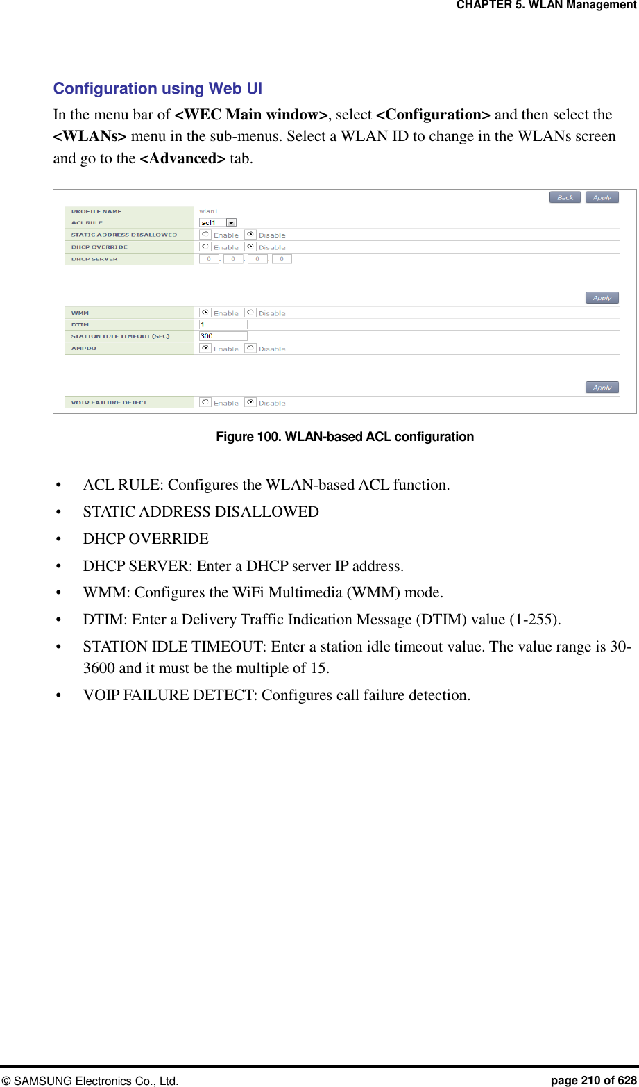
![CHAPTER 5. WLAN Management © SAMSUNG Electronics Co., Ltd. page 211 of 628 5.1.4 Managing Root Service To provide a wireless LAN service where cable installation is difficult, a W-EP AP can be configured as a repeater mode to relay wireless LAN traffics. To configure this kind of network, the Repeater AP and Root AP are required. The Repeater AP is working as a wireless terminal and the Root AP connects a Repeater AP to a wireless terminal for connection to the APC. The root AP must be enabled with the repeater service to allow repeater AP connections. Configuration using CLI 1) Go to configure apc configuration mode of CLI. WEC8500# configure terminal WEC8500/configure# apc WEC8500/configure/apc# 2) Enable or disable the repeater service. The repeater service must be enabled for the repeater AP to connect to the root AP. repeater-service: Enabled no repeater-service: Disabled 3) Use the ‘show wlan detail repeater’ command to check the root WLAN settings. WEC8500/configure/apc# show wlan detail repeater [Changing to Root AP] The procedure of changing a W-EP AP to a Root AP is as follows: 1) Go to configure mode of CLI. WEC8500# configure terminal 2) Check the registered AP list. WEC8500/configure# show ap summary 3) Go to AP configuration mode to change to a Root AP. WEC8500/configure# ap ap_1](https://usermanual.wiki/Samsung-Electronics-Co/WEA463E.Part-1/User-Guide-2696662-Page-211.png)
![CHAPTER 5. WLAN Management © SAMSUNG Electronics Co., Ltd. page 212 of 628 4) Configure it to a Root AP. WEC8500/ configure/ap ap_1# profile ap-mode rootAp 5) Restart the configured AP. [Changing to Repeater AP] The procedure of changing a W-EP AP to a Repeater AP is as follows: 1) Go to configure mode of CLI. WEC8500# configure terminal 2) Check the registered AP list. WEC8500/configure# show ap summary 3) Go to AP configuration mode of an AP that will be changed to a Repeater AP. WEC8500/configure# ap ap_2 4) Configure it to a Repeat AP. WEC8500/configure/ap ap_2# profile ap-mode repeaterAp 5) Restart the configured AP.](https://usermanual.wiki/Samsung-Electronics-Co/WEA463E.Part-1/User-Guide-2696662-Page-212.png)
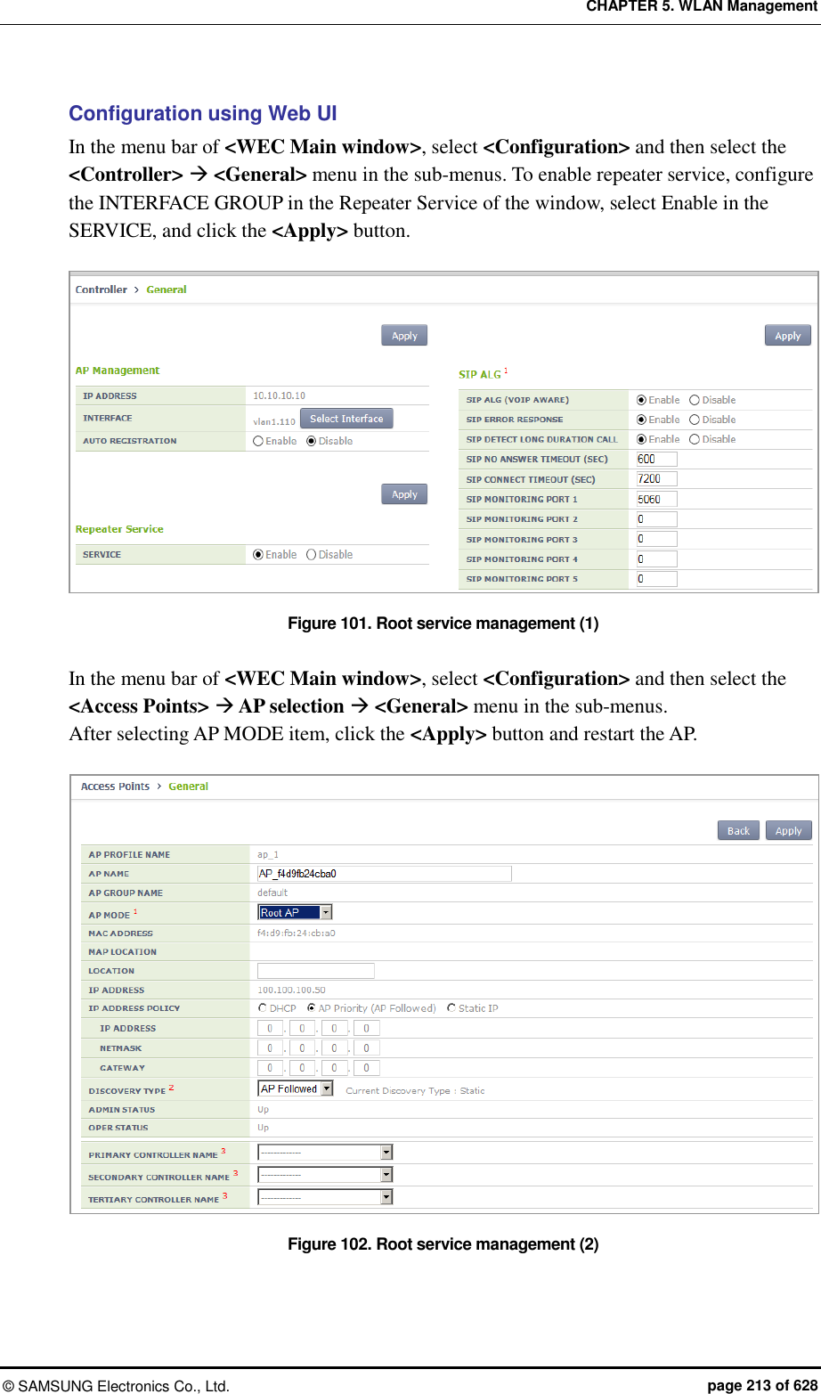
![CHAPTER 5. WLAN Management © SAMSUNG Electronics Co., Ltd. page 214 of 628 5.1.5 MCS Configuration Management by WLAN This is a function of configuring data rate and MCS by WLAN. You can configure MCS, etc. by each WLAN differently because it is necessary to configure MCS, etc. differently depending on the types of services such as FMC. Configuration using CLI 1) Go to configure WLAN configuration mode of CLI. WEC8500# configure terminal WEC8500/configure# wlan 1 WEC8500/configure/wlan 1 2) Go to 80211a or 80211b depending on the bandwidth to configure. WEC8500/configure/wlan 1# 80211a WEC8500/configure/wlan 1/80211a# 3) Configure the data rate. The settings described as shown below can be made only when the corresponding WLAN is set to be disabled. WEC8500/configure/wlan 1/80211a# rate [MODE][RATE] Parameter Description Mode Mode (basic/supported) - Basic: Basic rate supported for a terminal to access to an AP. - Supported: A connected terminal that supports the supported rate can communicate with an AP at the supported rate. RATE Data rate - Range for 80211a: 6, 9, 12, 18, 24, 36, 48, or 54 Mbps - Range for 80211b: 1, 2, 5.5, 6, 9, 11, 12, 18, 24, 36, 48, or 54 Mbps 4) Configure the 802.11n Modulation and Coding Scheme (MCS) rate. WEC8500/configure/wlan 1/80211a# mcs-11n [RATE] Parameter Description RATE MSC rate (Range: 0~23)](https://usermanual.wiki/Samsung-Electronics-Co/WEA463E.Part-1/User-Guide-2696662-Page-214.png)
![CHAPTER 5. WLAN Management © SAMSUNG Electronics Co., Ltd. page 215 of 628 5) Configure the 802.11ac Modulation and Coding Scheme (MCS) rate. Only 5G bandwidth for 802.11ac MCS is configurable. WEC8500/configure/wlan 1/80211a# mcs-11ac num-ss 2/3 enter the maximum MCS(7~9) for 1 spatial stream(s): 7 the maximum MCS : 7 enter the maximum MCS(7~9) for 2 spatial stream(s): 7 the maximum MCS : 7 enter the maximum MCS(7~9) for 3 spatial stream(s): 7 the maximum MCS : 7 [Wlan:1] Radio : 5GHz, number of SS: 3, max mcs : 7, 7, 7 Enable 6) You can check the configuration with the ‘show wlan detail #’ command. WEC8500# show wlan detail 1](https://usermanual.wiki/Samsung-Electronics-Co/WEA463E.Part-1/User-Guide-2696662-Page-215.png)
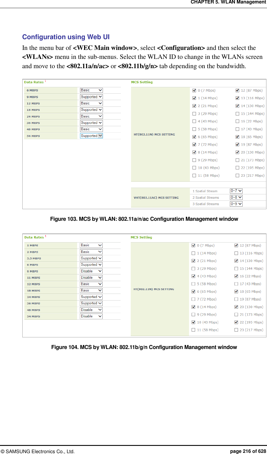
![CHAPTER 5. WLAN Management © SAMSUNG Electronics Co., Ltd. page 218 of 628 WEC8500# configure terminal WEC8500/configure# ap ap_1 WEC8500/configure/ap ap_1# profile WEC8500/configure/ap ap_1/profile# local-bridging [WLAN_ID][VLAN_ID/ACL_NAME/PRE_AUTH_ACL_NAME] Parameter Description WLAN_ID WLAN ID (Range: 1-254) (available only for WLANs the tunnel-mode of which is local-bridging) VLAN_ID VLAN ID (Range: 1-4094) ACL_NAME ACL name to configure for the WLAN service (only for options set in IP ACL) PRE_AUTH_ACL_NAME ACL name to configure for pre-authentication of the WLAN (only for options set in IP ACL) 4) Operator can check the configuration information by executing the ‘show remote-ap-group summary’, ‘show wlan detail’, ‘show ap local-bridging [AP_PROFILE_ NAME]’ command. Configuration using Web UI By referring to the ‘Configuring Remote AP Group’, add an AP to a remote AP group. In the menu bar of <WEC Main window>, select <Configuration> and then select the <WLANs> menu in the sub-menus. Select a WLAN ID to change in the WLANs screen and go to the <General> tab. After changing the ‘CAPWAP TUNNEL MODE’ to ‘Local Bridging’, click the <Apply> button. Figure 105. Local Switching Configuration Window of WLAN](https://usermanual.wiki/Samsung-Electronics-Co/WEA463E.Part-1/User-Guide-2696662-Page-218.png)
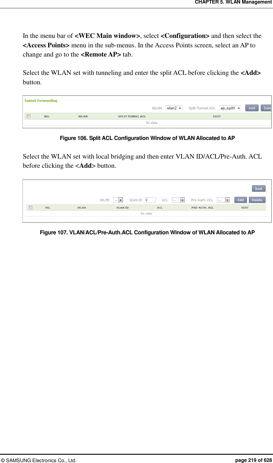
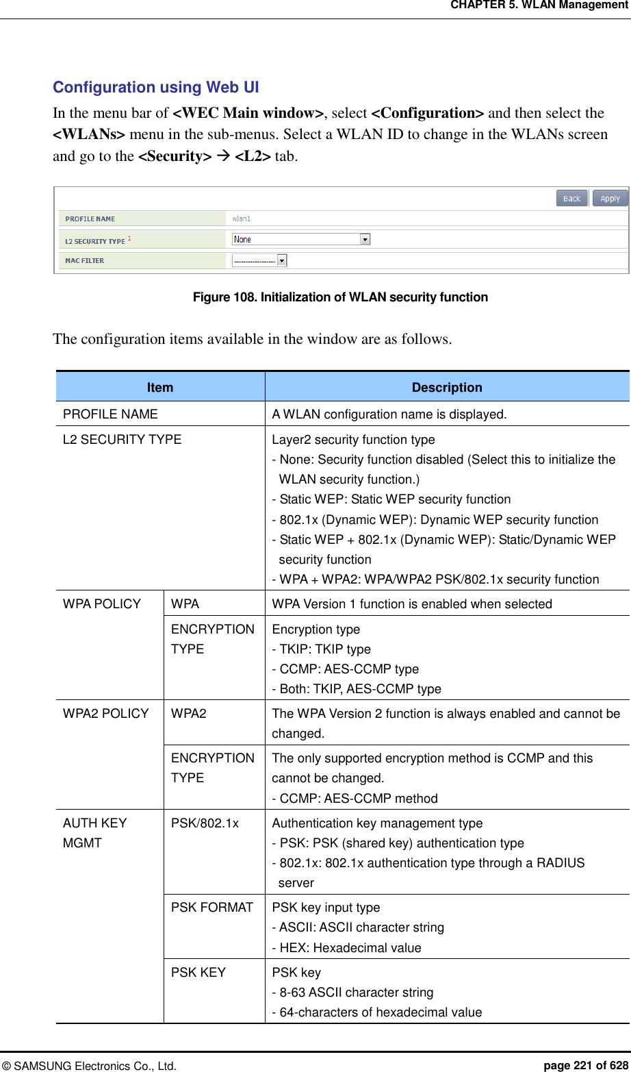
![CHAPTER 5. WLAN Management © SAMSUNG Electronics Co., Ltd. page 222 of 628 Item Description PMK LIFETIME PMK effective time (unit: s, range: 0-1000000, default: 43200) EAPOL REAUTHENTICATION PERIOD EAP re-authentication interval (unit: s, range: 0-100000, default: 0) STATIC WEP WEP KEY FORMAT key input format - ASCII: ASCII character string - HEX: Hexadecimal value WEP KEY SIZE Key length - 40: 40-bit (5-byte) - 104: 104-bit (13-byte) STATIC WEP WEP KEY INDEX Key index (1-4) WEP KEY key value 802.1X(DYNAMIC WEP) WEP KEY SIZE Key length - 40: 40-bit (5-byte) - 104: 104-bit (13-byte) After selecting the L2 Security Type as None, click the <Apply> button. 5.3.2 WPA/WPA2 PSK Configuration The WPA/WPA2 PSK, one of wireless LAN authentication types, can be used in a small size network where an authentication server is not installed. The procedure of WPA/ WPA2 PSK configuration is as follows. Configuration using CLI 1) Go to configure wlan configuration mode of CLI. WEC8500# configure terminal WEC8500/configure# wlan 1 2) Go to security configuration mode and initialize the configuration. WEC8500/configure/wlan 1# security WEC8500/configure/wlan 1/security# setDefault 3) Configure the WPA type. WEC8500/configure/wlan 1/security# [WPA_TYPE]](https://usermanual.wiki/Samsung-Electronics-Co/WEA463E.Part-1/User-Guide-2696662-Page-222.png)
![CHAPTER 5. WLAN Management © SAMSUNG Electronics Co., Ltd. page 223 of 628 Parameter Description WPA_TYPE WPA type (wpa/wpa2): WPA Version 2 must be enabled at all times. - wpa: WPA Version 1 - wpa2: WPA Version 2 4) Configure the PSK key. WEC8500/configure/wlan 1/security# psk [KEY_TYPE] [KEY_STRING] Parameter Description KEY_TYPE PSK key input format (ascii/hex) - ASCII: ASCII character string - HEX: Hexadecimal value KEY_STRING PSK key 5) Configure the encryption type. WEC8500/configure/wlan 1/security# [WPA_TYPE] [ENC_TYPE] Parameter Description WPA_TYPE WPA type (wpa/wpa2): Use the same value as the WPA type configured before. WPA Version 2 must be enabled at all times. - wpa: WPA Version 1 - wpa2: WPA Version 2 ENC_TYPE Encryption type (tkip/ccmp) - tkip: TKIP type. TKIP cannot be configured for WPA Version 2. - ccmp: AES-CCMP type 6) Configure the key management algorithm to PSK. WEC8500/configure/wlan 1/security# keymgmt psk 7) Disable the 802.1x key management algorithm. WEC8500/configure/wlan 1/security# no keymgmt ieee8021x](https://usermanual.wiki/Samsung-Electronics-Co/WEA463E.Part-1/User-Guide-2696662-Page-223.png)
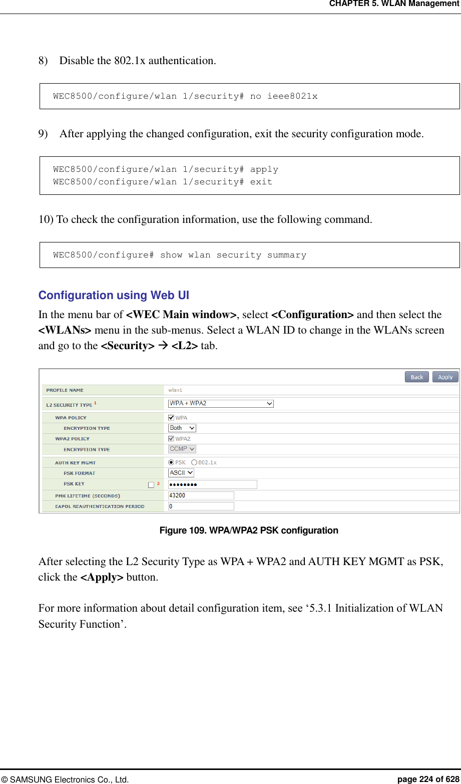
![CHAPTER 5. WLAN Management © SAMSUNG Electronics Co., Ltd. page 225 of 628 5.3.3 WPA/WPA2 802.1x Configuration The WPA/WPA2 802.1x, one of wireless LAN authentication types does authentication through an authentication server such as a Remote Authentication Dial-In User Service (RADIUS) server. To configure WPA/WPA2 802.1x to WLAN, execute the command as follows: As the 802.1x authentication needs interoperation with a RADIUS server, the RADIUS server required for the WLAN security configuration must be configured first. For more information about RADIUS server configuration, see ‘8.1 RADIUS Server Configuration’. Configuration using CLI 1) Go to configure wlan configuration mode of CLI. WEC8500# configure terminal WEC8500/configure# wlan 1 2) Go to security configuration mode and initialize the configuration. WEC8500/configure/wlan 1# security WEC8500/configure/wlan 1/security# setDefault 3) Configure the WPA type. WEC8500/configure/wlan 1/security# wpa_type Parameter Description wpa_type WPA type (wpa/wpa2): WPA Version 2 must be enabled at all times. - wpa: WPA Version 1 - wpa2: WPA Version 2 4) Configure the encryption type. WEC8500/configure/wlan 1/security# [WPA_TYPE] [ENC_TYPE] Parameter Description WPA_TYPE WPA type (wpa/wpa2): Use the same value as the WPA type configured before. WPA Version 2 must be enabled at all times. - wpa: WPA Version 1 - wpa2: WPA Version 2](https://usermanual.wiki/Samsung-Electronics-Co/WEA463E.Part-1/User-Guide-2696662-Page-225.png)
![CHAPTER 5. WLAN Management © SAMSUNG Electronics Co., Ltd. page 226 of 628 Parameter Description ENC_TYPE Encryption type (tkip/ ccmp) - tkip: TKIP type. TKIP cannot be configured for WPA Version 2. - ccmp: AES-CCMP type 5) Disable the PSK key management algorithm. WEC8500/configure/wlan 1/security# no keymgmt psk 6) Configure the key management algorithm to 802.1x. WEC8500/configure/wlan 1/security# keymgmt ieee8021x 7) Enable the 802.1x authentication. WEC8500/configure/wlan 1/security# ieee8021x 8) After enabling the RADIUS server function for authentication, specify the index of authentication RADIUS server. The RADIUS server information must be configured in advance. WEC8500/configure/wlan 1/security# radius-server auth-servers [RADIUS_SERVER_ID_LIST] Parameter Description RADIUS_SERVER_ID_LIST RADIUS server ID list (Up to 3 IDs can be configured.) 9) After enabling the RADIUS server function for accounting, specify the index of account RADIUS server. The RADIUS server information must be configured in advance. WEC8500/configure/wlan 1/security# radius-server acct-servers [RADIUS_SERVER_ID_LIST] Parameter Description RADIUS_SERVER_ID_LIST RADIUS server ID list (Up to 3 IDs can be configured.)](https://usermanual.wiki/Samsung-Electronics-Co/WEA463E.Part-1/User-Guide-2696662-Page-226.png)
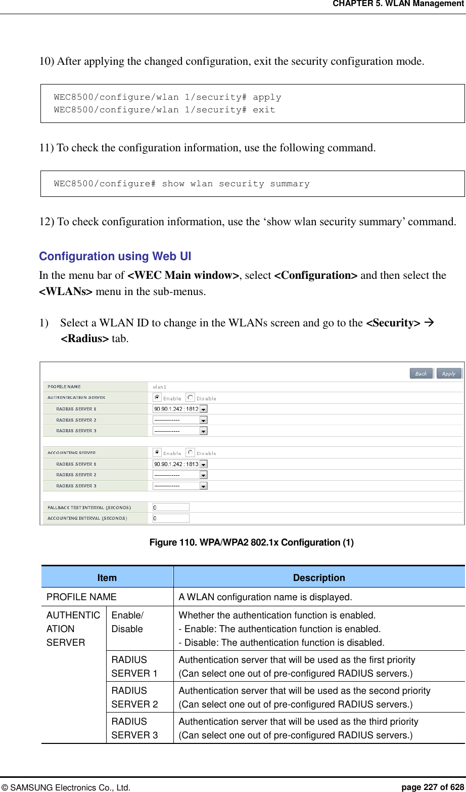
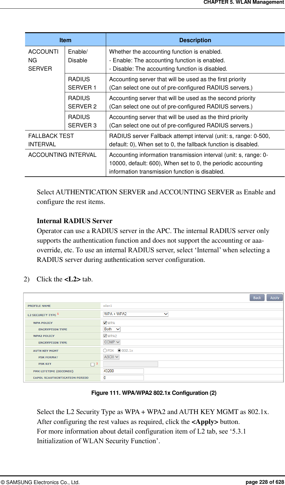
![CHAPTER 5. WLAN Management © SAMSUNG Electronics Co., Ltd. page 229 of 628 5.3.4 Static WEP Configuration The WEP is a security algorithm defined in the initial wireless LAN standard. It provides security by using a cryptographic key and Initial Vector (IV) to encrypt the wireless transmission data exchanged between an AP and a wireless terminal connected to a wireless LAN. Configuration using CLI For static WEP configuration, execute the following commands. 1) Go to configure wlan configuration mode of CLI. WEC8500# configure terminal WEC8500/configure# wlan 1 2) Go to security configuration mode and initialize the configuration. WEC8500/configure/wlan 1# security WEC8500/configure/wlan 1/security# setDefault 3) Disable WPA1, WPA2, and 802.1x authentication. WEC8500/configure/wlan 1/security# no wpa WEC8500/configure/wlan 1/security# no wpa2 WEC8500/configure/wlan 1/security# no ieee8021x 4) Enable the WEP. WEC8500/configure/wlan 1/security# wep 5) Configure the WEP Shared Key mode. WEC8500/configure/wlan 1/security# wep shared 6) Use the following command to configure the cryptographic key of WEP. WEC8500/configure/wlan 1/security# wep encryption [KEY_TYPE] [KEY_STRING] [KEY_INDEX] [KEY_LENGTH]](https://usermanual.wiki/Samsung-Electronics-Co/WEA463E.Part-1/User-Guide-2696662-Page-229.png)
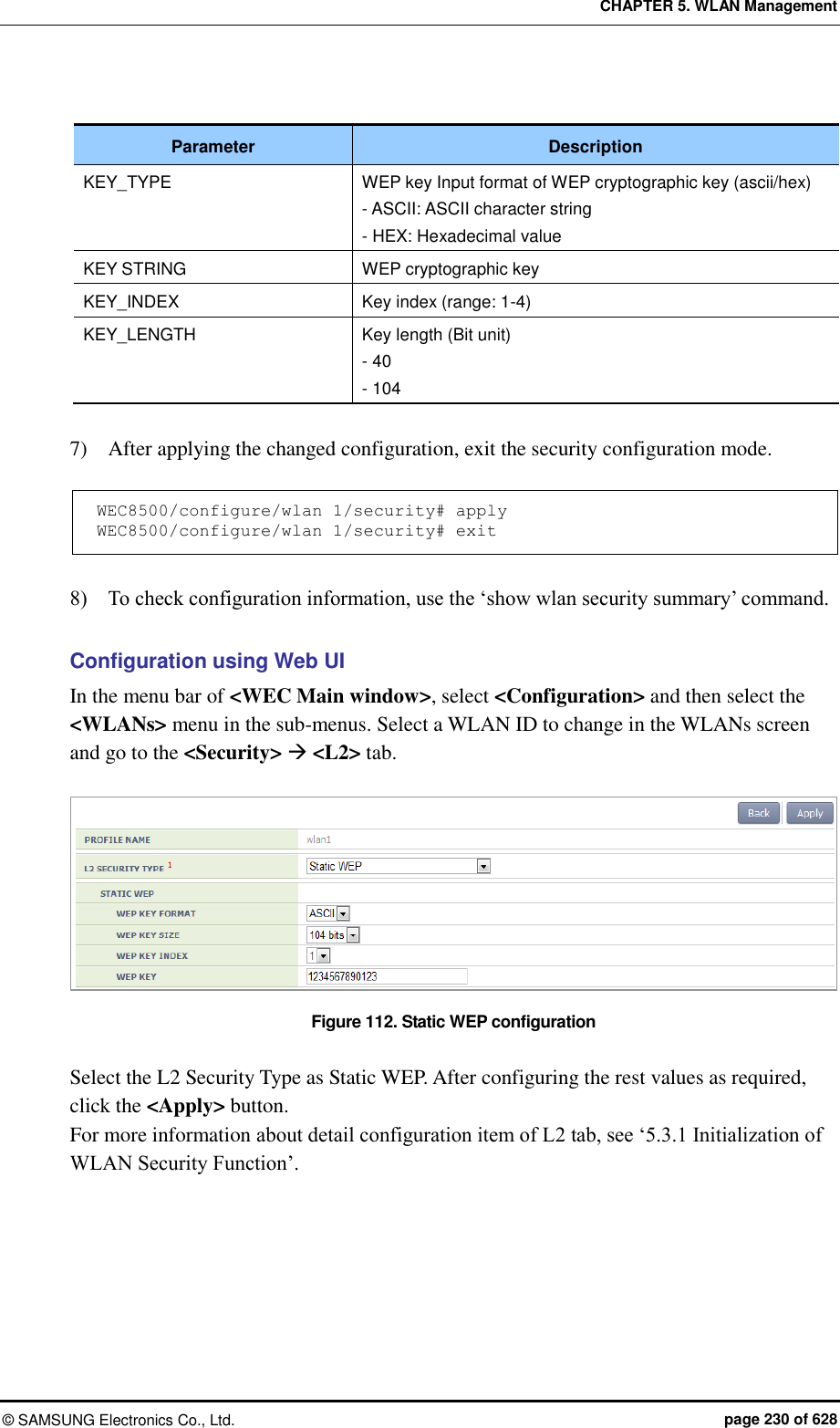
![CHAPTER 5. WLAN Management © SAMSUNG Electronics Co., Ltd. page 231 of 628 5.3.5 Dynamic WEP Configuration The Dynamic WEP is a security algorithm that improves the security vulnerabilities of a static WEP by using 802.1x authentication. Unlike the static WEP that is based on a configured fixed key, it creates a cryptographic key by executing 802.1x authentication when a terminal is connected. Configuration using CLI For dynamic WEP configuration, execute the command as follows: 1) Go to configure wlan configuration mode of CLI. WEC8500# configure terminal WEC8500/configure# wlan 1 2) Go to security configuration mode and initialize the configuration. WEC8500/configure/wlan 1# security WEC8500/configure/wlan 1/security# setDefault 3) Enable the 802.1x authentication. WEC8500/configure/wlan 1/security# ieee8021x 4) To configure the length of a cryptographic key of dynamic WEP, execute the following command. WEC8500/configure/wlan 1/security# ieee8021x encryption [KEY_LENGTH] Parameter Description KEY_LENGTH Key length (Bit unit) - 40 - 104 5) After enabling the RADIUS server function for authentication, specify the index of authentication RADIUS server. The RADIUS server information must be configured in advance. WEC8500/configure/wlan 1/security# radius-server auth-servers [RADIUS_SERVER_ID_LIST]](https://usermanual.wiki/Samsung-Electronics-Co/WEA463E.Part-1/User-Guide-2696662-Page-231.png)
![CHAPTER 5. WLAN Management © SAMSUNG Electronics Co., Ltd. page 232 of 628 Parameter Description RADIUS_SERVER_ID_LIST RADIUS server ID list (Up to 3 IDs can be configured.) 6) After enabling the RADIUS server function for accounting, specify the index of account RADIUS server. The RADIUS server information must be configured in advance. WEC8500/configure/wlan 1/security# radius-server acct-servers [RADIUS_SERVER_ID_LIST] Parameter Description RADIUS_SERVER_ID_LIST RADIUS server ID list (Up to 3 IDs can be configured.) 7) After applying the changed configuration, exit the security configuration mode. WEC8500/configure/wlan 1/security# apply WEC8500/configure/wlan 1/security# exit 8) To check the configuration information, execute the following command. WEC8500/configure# show wlan security summary 9) To check configuration information, execute the ‘show wlan security summary’ command.](https://usermanual.wiki/Samsung-Electronics-Co/WEA463E.Part-1/User-Guide-2696662-Page-232.png)
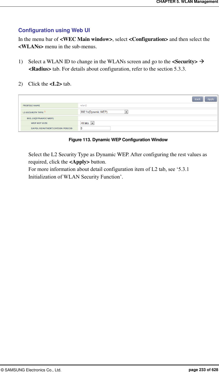
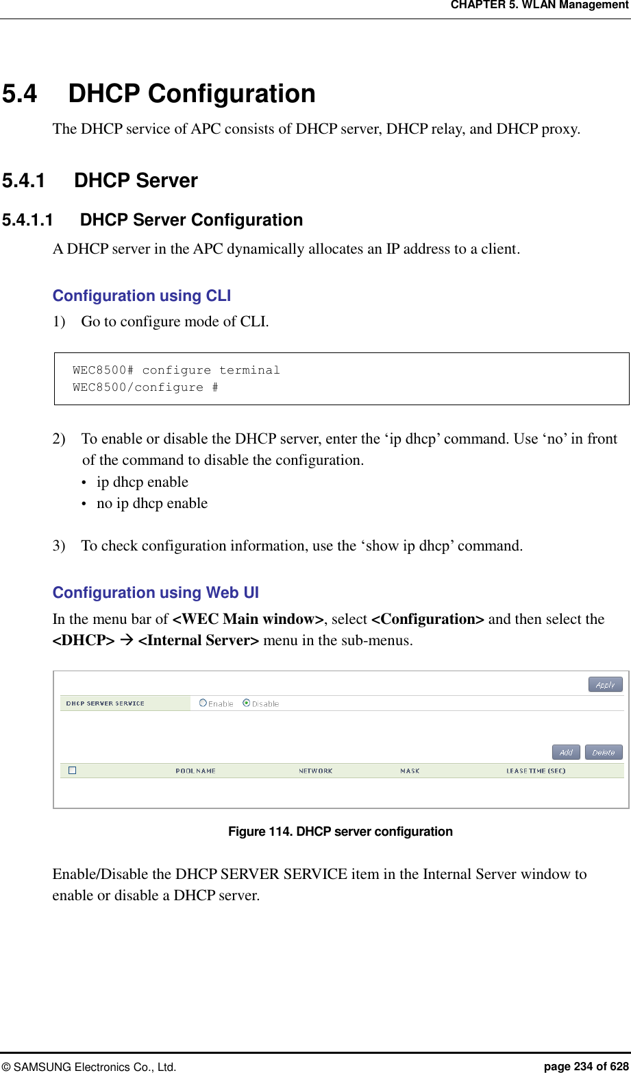
![CHAPTER 5. WLAN Management © SAMSUNG Electronics Co., Ltd. page 235 of 628 5.4.1.2 DHCP Pool The DHCP pool includes the range of IP address to be allocated to a client, DNS server that will be used by a DHCP client, NTP server, and default router IP address information, etc. Configuration using CLI [Pool Creation] The procedure of creating a pool in an internal DHCP server and entering into the pool mode is as follows: 1) Go to configure mode of CLI. WEC8500# configure terminal WEC8500/configure # 2) Enter the ‘ip dhcp pool’ command. Use ‘no’ in front of the command to delete a DHCP pool. ip dhcp pool [POOL_NAME] no ip dhcp pool [POOL_NAME] 3) To check configuration information, use the ‘show ip dhcp’ command. To configure the DHCP Pool related function, execute the command as follows to go to the DHCP pool mode. WEC8500# configure terminal WEC8500/configure # ip dhcp pool test WEC8500/configure/ip/dhcp/pool test# [Configuring IP address] Before configuring a DHCP pool, you should configure a network first. If the network is not configured, you cannot execute other commands. Enter the command as follows to configure the network bandwidth of a DHCP pool to serve. Enter ‘no’ parameter to delete a configured network bandwidth. After entering a separator ‘/’ after an IP address, enter the length of a netmask address or enter a netmask address after the IP address. network [IP_ADDRESS] [NETMASK] network [IP_ADDRESS]/[LENGTH] no network](https://usermanual.wiki/Samsung-Electronics-Co/WEA463E.Part-1/User-Guide-2696662-Page-235.png)
![CHAPTER 5. WLAN Management © SAMSUNG Electronics Co., Ltd. page 236 of 628 Parameter Description IP_ADDRESS IP address NETMASK Netmask address LENGTH Netmask length [Configuring Gateway] This command configures the gateway address of a DHCP client. Enter ‘no’ parameter to delete a configured address. default-router [IP_ADDRESS] no default-router Parameter Description IP_ADDRESS Gateway IP address [Configuring DNS Server] Up to 3 IP addresses can be configured for a DNS server. Enter ‘no’ parameter to delete a configured DNS server. The lower command ‘all’ is used to delete all the IP addresses of a configured DNS server. dns-server [IP_ADDRESS] no dns-server [IP_ADDRESS] no dns-server all Parameter Description IP_ADDRESS DNS Server’s IP address [Configuring Domain Name] This command configures or deletes a domain name. domain-name [DOMAIN] no domain-name [DOMAIN] Parameter Description DOMAIN Domain name to configure (e.g. samsung APC.co.kr)](https://usermanual.wiki/Samsung-Electronics-Co/WEA463E.Part-1/User-Guide-2696662-Page-236.png)
![CHAPTER 5. WLAN Management © SAMSUNG Electronics Co., Ltd. page 237 of 628 [Configuring Fixed IP Address to MAC Address] This command configures a fixed IP address to a specific MAC address or deletes the configuration. The ‘range’ of IP address to configure cannot be overlapped with the IP range and maximum 255 IP addresses can be configured. In addition, use the ‘no fix-address all’ command to delete all the configured values. fix-address [aa:bb:cc:dd:ee:ff A.B.C.D] no fix-address [aa:bb:cc:dd:ee:ff A.B.C.D] fix-address all As shown in the below example, 100.100.100.10 can be always allocated to the IP address of a wireless terminal whose MAC address is 11:22:33:44:55:66. WEC8500/configure/ip/dhcp/pool test# fix-address 11:22:33:44:55:66 100.100.100.10 [Configuring IP Address Lease Time] Configure the time when a wireless terminal receives an IP address. The ‘lease infinite’ command configures the time infinitely. If ‘no’ parameter is entered in front of the command, it is configured to 24 hours (default). lease [TIME] lease infinite no lease Parameter Description TIME Lease time (range: 120-8640000, Unit: s) [Configuring NTP Server] Up to 3 IP addresses of a NTP server can be configured or deleted. In addition, use the ‘no ntp-server all’ command to delete all the configured addresses of a NTP server. ntp-server [IP_ADDRESS] no ntp-server [IP_ADDRESS] no ntp-server all Parameter Description IP_ADDRESS The IP address of the NTP server](https://usermanual.wiki/Samsung-Electronics-Co/WEA463E.Part-1/User-Guide-2696662-Page-237.png)
![CHAPTER 5. WLAN Management © SAMSUNG Electronics Co., Ltd. page 238 of 628 [Ping check] When a DHCP server allocates an IP address to a client, ping check can be used to check if an IP address to allocate is being used in the current network. ping-check [enable/disable] Parameter Description enable/disable Configures whether to use ping check (default: disable) [Configuring IP Address Range] A DHCP server configures the range of IP address to allocate to a client. The range of IP address to add is up to 16 and the IP address specified in the range cannot be duplicated with the IP address of fix-address. Enter ‘no’ to delete the range of configured IP address and enter ‘no range all’ to delete all the ranges. range [IP_ADDRESS] range [IP_ADDRESS1] [IP_ADDRESS2] no range [IP_ADDRESS] no range [IP_ADDRESS1] [IP_ADDRESS2] no range all Parameter Description IP_ADDRESS IP address. Use to configure one IP address. IP_ADDRESS1 Start address of IP address range IP_ADDRESS2 Last address of IP address range [Capwap Access Controller Address Configuration] Up to three IP addresses for a Capwap controller can be configured or deleted. Also, all Capwap controller addresses can be deleted using the ‘no capwap-dhcp-option’ command. capwap-dhcp-option [IP_ADDRESS] no capwap-dhcp-option Parameter Description IP_ADDRESS IP address of the Capwap Controller [Configuring Option Data] Use the ‘user-option’ command to configure or delete the DHCP option. Use ‘no’ to delete each option and use ‘no user-option all’ to delete all the options. Option: Up to 254 can be entered (1-254). Data type: string (character string), octet (hex string), int (32 bit integer), uint (32-bit unsigned integer), int16 (16-bit integer), uint16 (16-bit unsigned integer), ipaddress (IP address)](https://usermanual.wiki/Samsung-Electronics-Co/WEA463E.Part-1/User-Guide-2696662-Page-238.png)
![CHAPTER 5. WLAN Management © SAMSUNG Electronics Co., Ltd. page 239 of 628 Mode: Can be configured to the active/passive mode. active: Although a client does not request data transmission, the DHCP server transmits user-option data (Default). passive: The DHCP server transmits data upon a client’s request. Command Description - user-option [1-254] string [string] [active/passive] - user-option [1-254] octet aa:bb:cc [active/passive] - user-option [1-254] int [integer] [active/passive] - user-option [1-254] uint [unsigned integer] [active/passive] - user-option [1-254] int16 [16 bit integer] [active/passive] - user-option [1-254] uint16 [16 bit unsigned integer] [active/passive] - user-option [1-254] ipaddress A.B.C.D [active/passive] Configures an option. - no user-option [1-254] string [string] [active/passive] - no user-option [1-254] octet aa:bb:cc [active/passive] - no user-option [1-254] int [integer] [active/passive] - no user-option [1-254] uint [unsigned integer] [active/passive] - no user-option [1-254] int16 [16 bit integer] [active/passive] - no user-option [1-254] uint16 [16 bit unsigned integer] [active/passive] - no user-option [1-254] ipaddress A.B.C.D [active/passive] Deletes a configured option. no user-option all Deletes all the configured options. A usage example is given below. WEC8500/configure/ip/dhcp/pool test# user-option 3 string “hi, there” active WEC8500/configure/ip/dhcp/pool test# user-option 200 octet 33:4A:5C:6F:DD passive WEC8500/configure/ip/dhcp/pool test# user-option 201 int -3000 WEC8500/configure/ip/dhcp/pool test# user-option 202 uint16 300 WEC8500/configure/ip/dhcp/pool test# user-option 203 ipaddress 111.22.22.33 [Retrieving Pool Information] To check the entire information of a DHCP pool, execute the ‘show ip dhcp pool’ command. If you enter a pool name as a parameter as shown in ‘show ip dhcp pool [POOL NAME]’, you can check the information of a specific pool. [Retrieving DHCP Lease Information] To check the DHCP lease information, execute the ‘show ip dhcp lease’ command.](https://usermanual.wiki/Samsung-Electronics-Co/WEA463E.Part-1/User-Guide-2696662-Page-239.png)
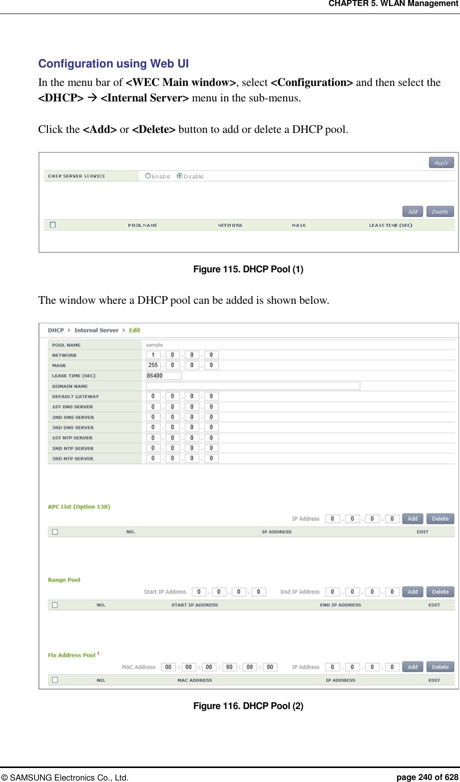
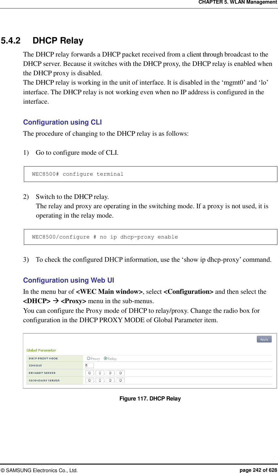
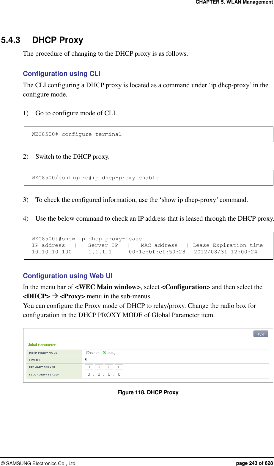
![CHAPTER 5. WLAN Management © SAMSUNG Electronics Co., Ltd. page 244 of 628 5.4.4 Option 82 Configuration The APC uses the DHCP Option 82 to provide various services during IP allocation by forwarding the information such as access control, QoS, or security policy, etc. when a wireless terminal connected to an AP receives an IP address. The Option 82 has two fields, i.e. remote ID and circuit ID. Enter the name of an interface for which the APC constantly does relay/proxy in the circuit ID and enter a part of AP information in the remote ID accordingly. One of the following three data can be used as the remote id of Option 82. ap-mac: 802.11 MAC data of the AP. The length is 12-byte (Default). ap-mac-ssid: The character string of SSID is added to the data of AP-MAC. The length is variable. ap-mac-ssid: Ethernet MAC data of the AP. The length is 12-byte. To configure Option 82 related functions, go to the interface mode by executing the following command. WEC8500# configure terminal WEC8500/configure#interface vlan10 WEC8500/configure/interface vlan10# Configuration using CLI [Configuring Option 82] This command enables or disables the Option 82 function. It can be configured for each interface. dhcp option-82 [MODE] Parameter Description MODE Configures whether to use the Option 82 function (enable/disable). [Configuring Remote ID] The command is shown below. dhcp option-82 remote-id [MODE] Parameter Description MODE Specifies one out of the following three data to the Option 82 remote-id. - ap-mac: MAC address of an AP - ap-mac-ssid: MAC address and SSID of an AP - ap- ethermac: Ethernet MAC address of an AP](https://usermanual.wiki/Samsung-Electronics-Co/WEA463E.Part-1/User-Guide-2696662-Page-244.png)
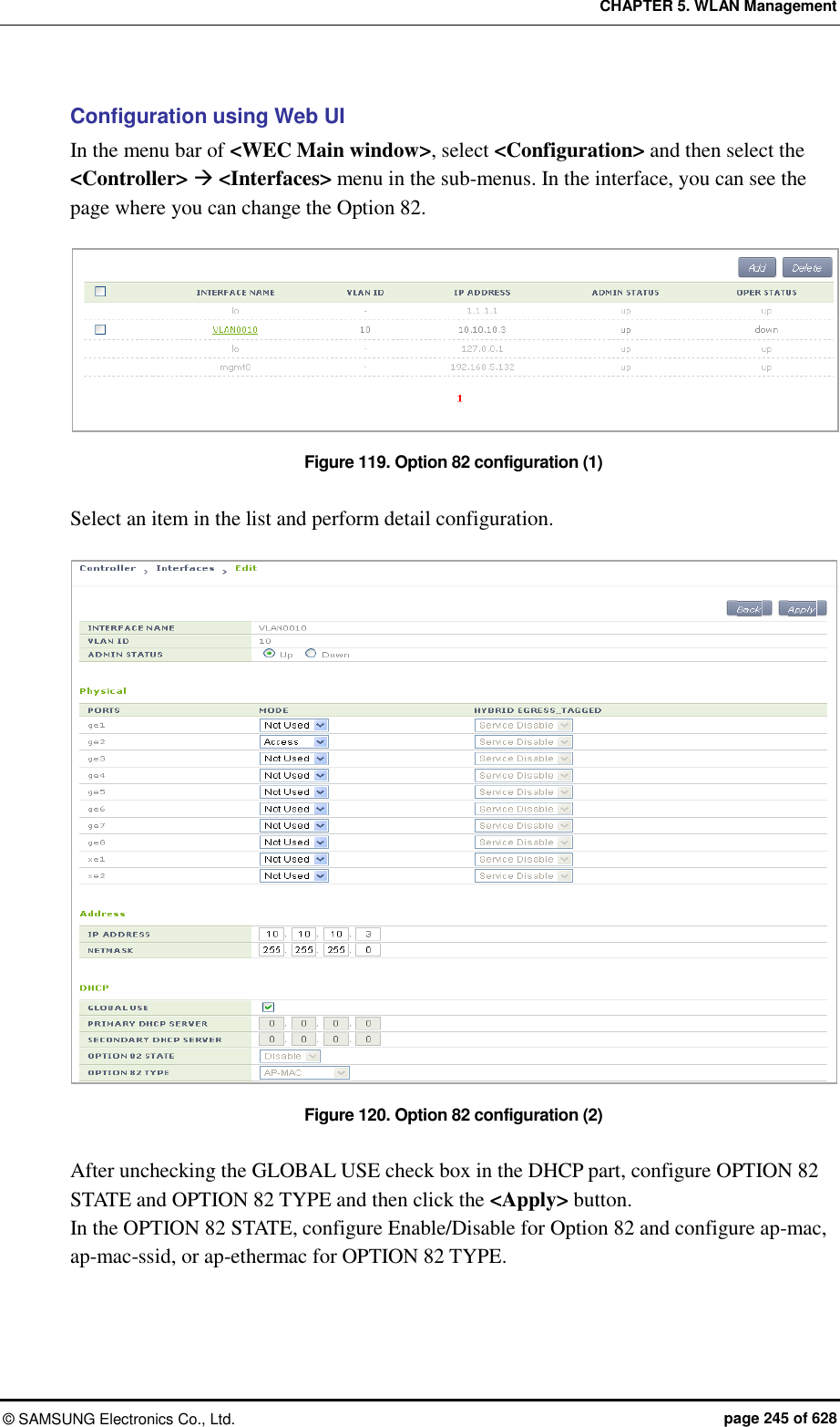
![CHAPTER 5. WLAN Management © SAMSUNG Electronics Co., Ltd. page 246 of 628 5.4.5 Primary/Secondary Server Configuration The DHCP relay/proxy can transmit a DHCP packet received from a client through broadcast to maximum two DHCP servers. Here, the two servers are called a primary server and a secondary server. The configuration of primary/secondary servers can be done in the interface mode, but it is also possible in the global mode. If the configuration exists both in the interface mode and global mode, the configuration in the interface mode has a higher priority. Configuration using CLI [Configuration at Interface] 1) Go to configure interface mode of CLI. WEC8500# configure terminal WEC8500/configure#interface [INTERFACE_NAME] 2) Enter the ‘dhcp server’ command. To configure only a primary server, do not enter the information of a secondary server. dhcp server primary A.B.C.D secondary A.B.C.D: Configures both primary/ secondary servers. dhcp server primary A.B.C.D: Configures only a primary server. no dhcp server primary A.B.C.D secondary A.B.C.D: Deletes both primary/ secondary servers. no dhcp server primary A.B.C.D: Deletes a primary server. [Configuration at Global] 1) Go to configure mode of CLI. WEC8500# configure terminal WEC8500/configure# 2) Enter the ‘ip dhcp-proxy default-dhcp-server’ command. To configure only a primary server, do not enter the information of a secondary server. ip dhcp-proxy default-dhcp-server primary A.B.C.D secondary A.B.C.D: Configures both global primary/secondary servers. ip dhcp-proxy default-dhcp-server primary A.B.C.D: Configures only a global primary server. no ip dhcp-proxy default-dhcp-server primary A.B.C.D secondary A.B.C.D: Deletes both global primary/secondary servers. no ip dhcp-proxy default-dhcp-server primary A.B.C.D: Deletes a global primary server.](https://usermanual.wiki/Samsung-Electronics-Co/WEA463E.Part-1/User-Guide-2696662-Page-246.png)
![CHAPTER 5. WLAN Management © SAMSUNG Electronics Co., Ltd. page 247 of 628 Configuration using Web UI [Configuration at Interface] In the menu bar of <WEC Main window>, select <Configuration> and then select the <Controller> <Interfaces> menu in the sub-menus. In the interface, you can see the page where you can change the Option 82. Figure 121. Primary/Secondary server configuration (1) Select an item in the list and perform detail configuration. Figure 122. Primary/Secondary server configuration (2) After unchecking the GLOBAL USE checkbox in the DHCP part, configure PRIMARY DHCP SERVER and ‘SECONDARY DHCP SERVER’ and then click the <Apply> button.](https://usermanual.wiki/Samsung-Electronics-Co/WEA463E.Part-1/User-Guide-2696662-Page-247.png)
![CHAPTER 5. WLAN Management © SAMSUNG Electronics Co., Ltd. page 248 of 628 [Configuration at Global] In the menu bar of <WEC Main window>, select <Configuration> and then select the <DHCP> <Proxy> menu in the sub-menus. Configure the PRIMARY SERVER and SECONDARY SERVER of the Global Parameter. If you does Global configuration, the configuration is applied to all the interfaces whose ‘GLOBAL USE’ checkbox is checked in the DHCP configuration of APC interface. Figure 123. Primary/Secondary server configuration (3)](https://usermanual.wiki/Samsung-Electronics-Co/WEA463E.Part-1/User-Guide-2696662-Page-248.png)
![CHAPTER 5. WLAN Management © SAMSUNG Electronics Co., Ltd. page 249 of 628 5.5 Radio Service Configuration The APC supports WLAN-based radio configuration. You can enable or disable WMM based on WLAN and change DTIM and station idle timeout. Configuration using CLI 1) Go to configure wlan-radio-service mode of CLI. APC# configure terminal APC/configure# wlan-radio-service APC/configure/wlan-radio-service# 2) Configure whether to enable or disable WMM. wmm-mode [WLAN_ID] [MODE] Parameter Description WLAN_ID WLAN ID (range: 1-240) MODE WMM configuration mode (disable/enable) 3) Configure DTIM. dtim [WLAN_ID] [DTIM] Parameter Description WLAN_ID WLAN ID (range: 1-240) DTIM Beacon DTIM: 1~255(default: 1) 4) Configure station idle timeout. sta-idle-timeout [WLAN_ID] [TIMEOUT] Parameter Description WLAN_ID WLAN ID (range: 1-240) TIMEOUT Station idle timeout (range: 30-3600, unit: 15 s, default: 300) 5) To check the configured information, use the ‘show wlan-radio-service’ command.](https://usermanual.wiki/Samsung-Electronics-Co/WEA463E.Part-1/User-Guide-2696662-Page-249.png)
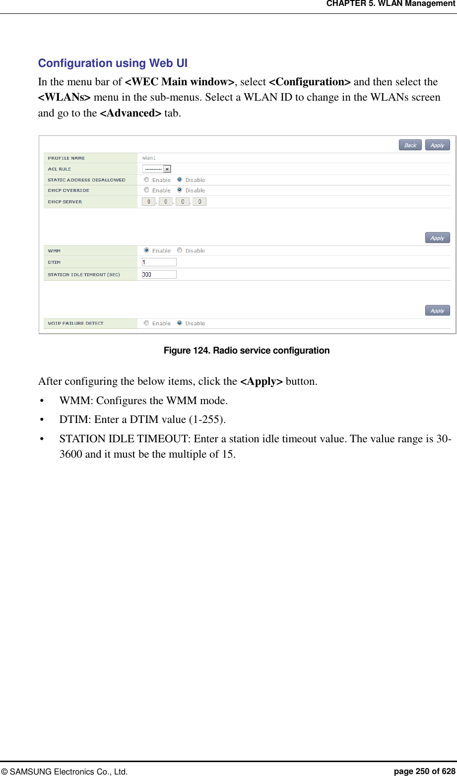
![CHAPTER 6. Wi-Fi Configuration © SAMSUNG Electronics Co., Ltd. page 251 of 628 CHAPTER 6. Wi-Fi Configuration This chapter describes how to manage the 802.11a, 80211.bg, 802.11n or 80211ac device of W-EP AP. An 802.11n device supports 2.4 GHz and 5 GHz wireless bandwidth and high data processing speed. 6.1 802.11a/b/g/n/ac Radio Property 6.1.1 802.11a/b/g Configuration The configuration of radio property for 802.11a/b/g/ac is as follows: Configuration using CLI 1) Go to configure radio mode to configure of CLI. The radio mode can be either ‘80211a’ or ‘80211bg’. An example of entering into 80211a is shown below. APC# configure terminal APC/configure# 80211a APC/configure/80211a# 2) Configure the channel of an AP. channel [CHANNEL] ap [AP_ID]: Configures the channel of an AP. channel [CHANNEL] ap [AP_ID] fixed: A channel is designed to be fixed and it is not affected by the automatic adjustment function such as RRM. (When executing the ‘show 80211a summary’ or ‘show 80211bg summary’, the channel value is displayed in ‘*’.) Parameter Description CHANNEL Channel Configuration - Range for 80211a: 36-165 - Range for 80211bg: 1-14 AP_ID AP ID (range: 1-3000)](https://usermanual.wiki/Samsung-Electronics-Co/WEA463E.Part-1/User-Guide-2696662-Page-251.png)
![CHAPTER 6. Wi-Fi Configuration © SAMSUNG Electronics Co., Ltd. page 252 of 628 3) Configure channel of multiple APs belonging to the group. channel [CHANNEL] group [GROUP_ID] all-ap/active-ap: Channel is configured for multiple APs. channel [CHANNEL] group [GROUP_ID] all-ap/active-ap fixed: Channel is fixed and is not affected by automatic adjustment functions such as RRM. (Channel values are indicated as * when retrieved by ‘show 80211a summary’ or ‘show 80211bg summary’.) Parameter Description CHANNEL Channel Configuration - Range for 80211a: 36-165 - Range for 80211bg: 1-14 GROUP_ID ID of the AP group all-ap Applies to all APs in the group active-ap Applies to all live APs in the group 4) Configure the TX power of an AP. txPower [POWER] ap [AP_ID]: Configures a TX power. txPower [POWER] ap [AP_ID]fixed: The TX power is configured as fixed and it is not affected by the automatic adjustment function such as RRM. (When executing the ‘show 80211a summary’ or ‘show 80211bg summary’, the channel value is displayed in ‘*’.) Parameter Description POWER TX power value (range: 3-23) AP_ID AP ID (range: 1-3000) 5) Configure TX power of multiple APs belonging to the group. txPower [POWER] group [GROUP_ID] all-ap/active-ap: TX Power Setting txPower [POWER] group [GROUP_ID] all-ap/active-ap fixed: TX power is fixed and is not affected by automatic adjustment functions such as RRM. (Channel values are indicated as * when retrieved by ‘show 80211a summary’ or ‘show 80211bg summary’.) Parameter Description POWER TX power value (range: 3-23) GROUP_ID ID of the AP group all-ap Applies to all APs in the group active-ap Applies to all live APs in the group](https://usermanual.wiki/Samsung-Electronics-Co/WEA463E.Part-1/User-Guide-2696662-Page-252.png)
![CHAPTER 6. Wi-Fi Configuration © SAMSUNG Electronics Co., Ltd. page 253 of 628 6) To check the configured channel and TX power information, use the following command. WEC8500# show 80211a[|80211bg] summary AP Name MAC Address Operation State Channel TxPower ----------------- ----------------- --------------- -------- -------- AP_f4d9fb23bfb9 F4:D9:FB:23:BF:B9 1 161 10 * AP_f4d9fb23c2b9 F4:D9:FB:23:C2:B9 1 157 5 AP_f4d9fb23c079 F4:D9:FB:23:C0:79 1 153 5 AP_f4d9fb23baf9 F4:D9:FB:23:BA:F9 1 149 5 AP_f4d9fb23beb9 F4:D9:FB:23:BE:B9 1 64 5 In this example, the AP_f4d9fb23bfb9 whose Tx Power is displayed as 10* has a fixed TX power. 7) Configure the beacon period of an AP. beacon period [PERIOD] global Parameter Description PERIOD Beacon period (range: 40-3500) 8) Configure the fragmentation threshold of an AP. threshold fragmentation [THRESHOLD] global Parameter Description THRESHOLD Fragmentation threshold (range: 256-8000) 9) Configure the data rate of an AP. rate [MODE] [RATE] global Parameter Description MODE Mode (basic/supported) - basic: Basic rate at which a terminal connects to an AP. - supported: A connected terminal that supports the supported rate can communicate with an AP at the supported rate. RATE Data rate - Range for 80211a: 6, 9, 12, 18, 24, 36, 48, or 54 Mbps - Range for 80211bg: 1, 2, 5.5, 6, 9, 11, 12, 18, 24, 36, 48, or 54 Mbps 10) To check the configured beacon period, fragmentation threshold, and data rate information, uses the ‘show 80211a radio-config global’ command.](https://usermanual.wiki/Samsung-Electronics-Co/WEA463E.Part-1/User-Guide-2696662-Page-253.png)
![CHAPTER 6. Wi-Fi Configuration © SAMSUNG Electronics Co., Ltd. page 254 of 628 11) Configure the bandwidth of the AP. Bandwidth can be configured only for 80211a/n/ac. bandwidth [BANDWIDTH] ap [AP_ID]: Bandwidth is configured for a specific AP. bandwidth [BANDWIDTH] global: Bandwidth is configured for all APs. Parameter Description BANDWIDTH - 20: 20 MHz - 40: 40 MHz - 80: 80 MHz - 160: 160 MHz (to be supported in the future) - 8080: 80 + 80 MHz (to be supported in the future) AP_ID ID of the AP (range: 1-3000) Configuration using Web UI In the menu bar of <WEC Main window>, select <Configuration> and then select the <Access Points> <802.11a/n> or <802.11b/g/n> menu in the sub-menus. An example of selecting 802.11a/n is shown below. Figure 125. 802.11a/b/g/n radio (1) The configuration items are as follows: [AP Service Configuration] SERVICE: Enable or disable the radio service. [Channel Configuration] CURRENT CHANNEL: Configures a channel. Range for 80211a: 36-165 Range for 80211bg: 1-14 CHANNEL FIX: The configured channel is configured as fixed and it is not affected by the automatic adjustment function such as RRM. When selecting the <Monitor> <Access Points> <Radio> <802.11a/n/ac> or <802.11b/g/n> menu, the channel value is displayed as *. (Optional)](https://usermanual.wiki/Samsung-Electronics-Co/WEA463E.Part-1/User-Guide-2696662-Page-254.png)
![CHAPTER 6. Wi-Fi Configuration © SAMSUNG Electronics Co., Ltd. page 255 of 628 [TX power Configuration] TX CURRENT POWER: TX Power (range: 3-23) TX POWER FIX: The configured TX power is configured as fixed and it is not affected by the automatic adjustment function such as RRM. When selecting the <Monitor> <Access Points> <Radio> <802.11a/n/ac> or <802.11b/g/n> menu, the Tx power value is displayed as *. (Optional) To check the configured channel and TX power information, go to <Monitor> <Access Points> <Radio> <802.11a/n/ac> or <802.11b/g/n>. In the menu bar of <WEC Main window>, select <Configuration> and then select the <Radio> <802.11a/n/ac> or <802.11b/g/n> <802.11h> menu in the sub-menus. An example of selecting 802.11a/n/ac is shown below. Figure 126. 802.11a/b/g/n radio (2) [General] BANDWIDTH: Configures bandwith (range: 20, 40, 80). Available for 802.11a/n/ac only. BEACON PERIOD: Beacon period (range: 40-3500) FRAGMENTATION THRESHOLD: AP fragmentation threshold (range: 256-8000) MAX. CLIENT COUNTS: Limits the number of connected clients per radio CONTROLLED VOICE OPTIMIZATION: Configures voice optimization. [Data Rates] The data rate selection options are as follows: Basic: Basic rate supported for a terminal to connect to an AP. Supported: A connected terminal that supports the supported rate can communicate with an AP at the supported rate. Data Rates: data rate Range for 80211a: 6, 9, 12, 18, 24, 36, 48, or 54 Mbps Range for 80211bg: 1, 2, 5.5, 6, 9, 11, 12, 18, 24, 36, 48, or 54 Mbps](https://usermanual.wiki/Samsung-Electronics-Co/WEA463E.Part-1/User-Guide-2696662-Page-255.png)
![CHAPTER 6. Wi-Fi Configuration © SAMSUNG Electronics Co., Ltd. page 256 of 628 6.1.2 802.11n Configuration The 802.11n configuration is as follows: Configuration using CLI 1) Go to configure radio mode (80211a or 80211bg) to configure of CLI. WEC8500# configure terminal WEC8500/configure# 80211a 2) Go to the 11n-support mode. WEC8500/configure/80211a#11n-support 3) Configure an AP so that it can support 802.11n property. WEC8500/configure/80211a/11n-support# enable [AP_ID] Parameter Description AP_ID AP ID (range: 1-500) 4) Configure the Modulation and Coding Scheme (MCS) rate. WEC8500/configure/80211a/11n-support# mcs [RATE] ap [AP_ID] Parameter Description RATE MSC rate (range: 0-23) AP_ID AP ID (range: 1-500) 5) To check the configured 11n-support information, use the ‘show 80211a radio-config ap [AP_ID]’ command. Configuration using Web UI In the menu bar of <WEC Main window>, select <Configuration> and then select the <Access Points> <802.11a/n/ac> or <802.11b/g/n> <General> menu in the sub-menus. Perform the configuration by referring to ‘6.1.1 802.11a/b/g Configuration’.](https://usermanual.wiki/Samsung-Electronics-Co/WEA463E.Part-1/User-Guide-2696662-Page-256.png)
![CHAPTER 6. Wi-Fi Configuration © SAMSUNG Electronics Co., Ltd. page 257 of 628 6.1.3 802.11ac Configuration The 802.11ac configuration is as follows: Configuration using CLI 1) Go to configure radio mode of 80211a to configure. WEC8500# configure terminal WEC8500/configure# 80211a 2) Enter 11ac-support mode. WEC8500/configure/80211a#11ac-support 3) Configure the AP so that it can support the 802.11ac property. WEC8500/configure/80211a/11ac-support# enable [AP_ID] Parameter Description AP_ID ID of the AP (range: 1-500) 4) Configure the Modulation and Coding Scheme (MCS) rate. WEC8500/configure/80211a/11n-support# mcs [RATE] ap [AP_ID] Parameter Description RATE MSC rate (range: 0-23) AP_ID ID of the AP (range: 1-500) 5) To check the configured 11ac-support information, use the ‘show 80211a radio-config ap[AP_ID]’ command. Configuration using Web UI In the menu bar of <WEC Main Window>, select <Configuration> and then select <Access Points> <802.11a/n/ac> or <Radio> <802.11a/n/ac> <802.11n/ac> in the submenu. An example of selecting 802.11a/n/ac is shown below.](https://usermanual.wiki/Samsung-Electronics-Co/WEA463E.Part-1/User-Guide-2696662-Page-257.png)
![CHAPTER 6. Wi-Fi Configuration © SAMSUNG Electronics Co., Ltd. page 258 of 628 [OPERATIONAL TYPE] Enable/disable 11ac operation. [VHT (802.11AC) MCS SETTING] Determine the spatial stream count for each AP model and enter maximum MCS value for each spatial stream count. Example: maximum of seven MCS for one spatial stream, maximum of eight MCS for two spatial streams, and maximum of nine MCS for three spatial streams 1 spatial stream: 7 2 spatial streams: 8 3 spatial streams: 9 [OPTIONS] Guard-interval (11n): Select short/long for Guard-interval 20/40 Mhz respectively. Guard-interval (11ac): Select short/long for Guard-interval 20/40/80 Mhz respectively.](https://usermanual.wiki/Samsung-Electronics-Co/WEA463E.Part-1/User-Guide-2696662-Page-258.png)
![CHAPTER 6. Wi-Fi Configuration © SAMSUNG Electronics Co., Ltd. page 259 of 628 6.2 Wi-Fi QoS Configuration The APC provides various QoS in the wire/wireless section for every packet type (voice, video, best-effort, or background). The QoS can be configured for each wireless section (2.4 GHz, 5 GHz). 6.2.1 QoS Configuration of Wireless Terminal The system provides probable QoS by changing the Enhanced Distributed Channel Access (EDCA) parameter in a wireless section. Configuration using CLI To configure an EDCA profile in the upward wireless section of a wireless terminal, execute the command as follows: 1) Go to configure radio mode to configure of CLI. APC# configure terminal APC/configure# [80211a/80211bg] 2) Apply the EDCA profile. edca-parameters [PROFILE] station Parameter Description PROFILE Configures each EDCA profile (wmm_default_sta/wmm_default_ap/ edca_user1/edca_user2). 3) To check the application status of a configured EDCA profile, use the ‘show 80211a [80211bg] qos edca-parameters wmm_default_sta’ command. Configuration using Web UI In the menu bar of <WEC Main window>, select <Configuration> and then select the <Radio> <802.11a/n> or <802.11b/g/n> <QoS> menu in the sub-menus. In the Qos menu, there are Wired and Wireless tab. To change the Station EDCA parameter, select the Wired tab. If you want to change the AP EDCA parameter to configure the QoS of an AP wireless section, select the Wireless tab.](https://usermanual.wiki/Samsung-Electronics-Co/WEA463E.Part-1/User-Guide-2696662-Page-259.png)
![CHAPTER 6. Wi-Fi Configuration © SAMSUNG Electronics Co., Ltd. page 260 of 628 [Wired tab] Figure 127. QoS configuration of a wireless terminal (1) [Wireless tab] Figure 128. QoS configuration of a wireless terminal (2)](https://usermanual.wiki/Samsung-Electronics-Co/WEA463E.Part-1/User-Guide-2696662-Page-260.png)
![CHAPTER 6. Wi-Fi Configuration © SAMSUNG Electronics Co., Ltd. page 261 of 628 6.2.2 QoS Configuration of AP 6.2.2.1 Wire Section The APC provides QoS in a wire section using 802.1p and Differentiated Services Code Point (DSCP) marking and it can adjust packet traffics because it can adjust queue length depending on packet type. Configuration using CLI To configure the Station QoS parameter that will be applied to the wire section between APC and AP, execute the command as follows: 1) Go to configure QoS mode of a wireless section of CLI. APC# configure terminal APC/configure# [80211a/80211bg] qos APC/configure/80211a/qos# 2) Configure a QoS policy to a wire section packet. 802.1P Policy: enable policy [802_1P] DSCP Policy: enable policy [DSCP_OUTER] [DSCP_INNER] Parameter Description enable Enables 802.1p or DSCP marking. 802_1P 802.1p configuration (user_priority/default) - user_priority: Marks the 802.1p or User Priority value of an incoming packet into the 802.1p field. - default: Marks pre-configured basic value to the 802.1p field. DSCP_OUTER DSCP Outer configuration (inner_packet/default) - inner_packet: Marks the DSCP value of an incoming packet into the Outer DSCP field. - default: Marks pre-configured basic value to the Outer DSCP field. DSCP_INNER DSCP Inner configuration (no_mark/default) - no_mark: Marks no value into the Inner DSCP field. - default: Marks pre-configured basic value to the Inner DSCP field. 3) Configure a default 802.1p value per packet. dot1p-tag [PACKET_TYPE] [802.1P_TAG] Parameter Description PACKET_TYPE Packet type configuration (voice/video/best_effort/background) 802.1P_TAG Default 802.1p value](https://usermanual.wiki/Samsung-Electronics-Co/WEA463E.Part-1/User-Guide-2696662-Page-261.png)
![CHAPTER 6. Wi-Fi Configuration © SAMSUNG Electronics Co., Ltd. page 262 of 628 4) Configure a default DSCP value per packet. dscp-tag [PACKET_TYPE] [DSCP TAG] Parameter Description PACKET_TYPE Packet type configuration (voice/video/best_effort/background) DSCP_TAG Default DSCP value 5) Configure a protocol to distinguish packet types. protocol [PROTOCOL] Parameter Description PROTOCOL Protocol configuration (none/dot1p/dscp) - none: Determine the type of every incoming packet with best effort. - dot1p: Judge the packet type by checking the 802.1p field of an incoming packet. - dscp: Judge the packet type by checking the DSCP field of an incoming packet. The packet judgment criteria are as follows: For example, if the packet type is voice, the 802.1p input value is 6 or 7 and the input range of DSCP value is 46-63. Also, if the packet type is video, the 802.1p input value is 4 or 5 and the input range of DSCP value is 24-45. 802.1p DSCP Packet type 6, 7 46~63 voice 4, 5 24~45 video 0, 3 0~7, 16~23 best effort 1, 2 8~15 background 6) To check the configured policy and QoS parameter information per packet, use the ‘show 80211a[|80211bg] qos policy’ command.](https://usermanual.wiki/Samsung-Electronics-Co/WEA463E.Part-1/User-Guide-2696662-Page-262.png)
![CHAPTER 6. Wi-Fi Configuration © SAMSUNG Electronics Co., Ltd. page 263 of 628 Configuration using Web UI In the menu bar of <WEC Main window>, select <Configuration> and then select the <Radio> <802.11a/n> or <802.11b/g/n> <QoS> menu in the sub-menus. 1) Select one out of None/Default/User Priority in the 802.1P POLICY drop-down list of Tagging Policy. 2) To disable a DSCP policy in the DSCP POLICY, select Disable. 3) To enable a DSCP policy in the DSCP POLICY, select Enable. a) Select one out of Inner Packet/Default Value in the OUTER DSCP drop-down list. b) Select one out of No Mark/Default Value in the INNER DSCP drop-down list. 4) Select one out of None/802.1p/DSCP in the PROTOCOL drop-down list. 5) Enter 802.1p or a DSCP value into the QoS Default Values. 6) Click the <Apply> button to apply. 6.2.2.2 Wireless Section The system can provide QoS service in a wireless section for each AP downward packet type (voice, video, best effort, background). You can configure 802.1p and DSCP tag which are the criteria used to select access category. Configuration using CLI 1) Go to configure QoS mode of a wireless section of CLI. APC# configure terminal APC/configure# [80211a/80211bg] qos APC/configure/80211a/qos# 2) Configure 802.1p or DSCP tag value to use for a packet type. ap-tags [PACKET_TYPE] [802.1P TAG] [DSCP TAG] Parameter Description PACKET_TYPE Packet type configuration (voice/video/best_effort/background) 802.1P_TAG 802.1p configuration DSCP_TAG DSCP tag configuration 3) To check the QoS parameter information of a configured AP, use the ‘show 80211a [80211bg] qos ac-profile [PACKET_TYPE]’ command.](https://usermanual.wiki/Samsung-Electronics-Co/WEA463E.Part-1/User-Guide-2696662-Page-263.png)
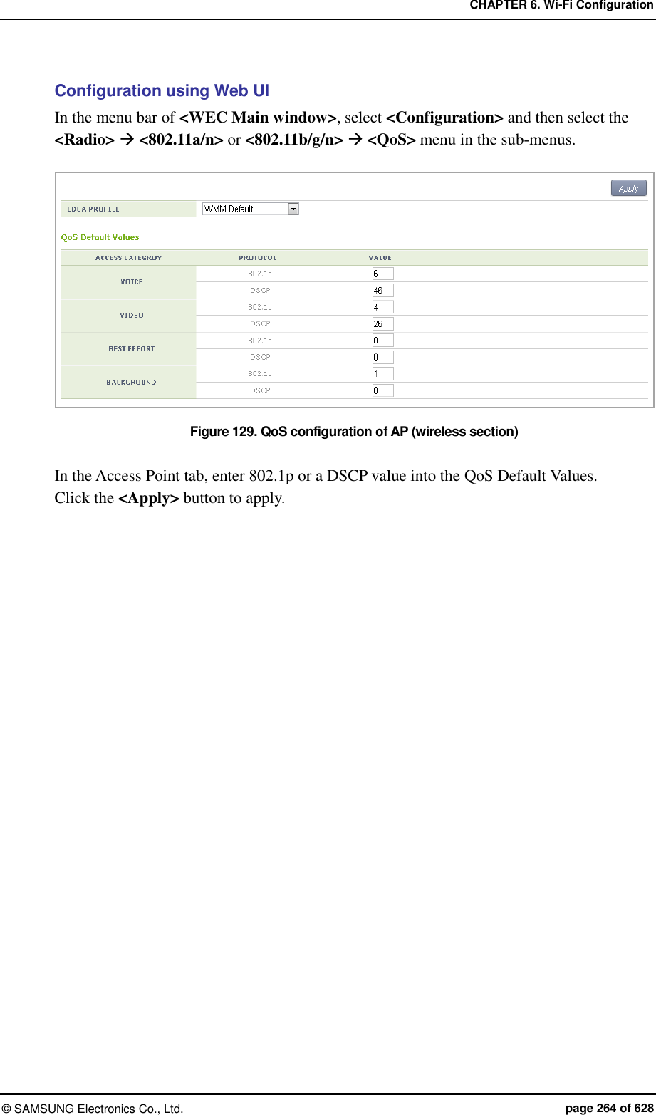
![CHAPTER 6. Wi-Fi Configuration © SAMSUNG Electronics Co., Ltd. page 265 of 628 6.2.3 Configuring QoS Profile of a Specific Terminal You can configure a QoS profile that is applied to a specific wireless terminal. This QoS profile is applied from the RADIUS server of a wireless terminal during authentication. Configuration using CLI 1) Go to configure QoS profile configuration mode of CLI. APC# configure terminal APC/configure# qos <profile name> APC/configure/qos Samsung # 2) Configure 802.1p and a DSCP value that will be used for each access category. ac [AC] [802.1P_TAG] [DSCP_TAG] Parameter Description AC Access Category(AC_VO/AC_VI/AC_BE/AC_BK) 802.1P_TAG 802.1p configuration (range: 0-7) DSCP_TAG DSCP tag configuration (range: 0-63) 3) Configure the brief information of a profile. description [DESCRIPTION] Parameter Description DESCRIPTION Profile description 4) Configure maximum allowed 802.1p priority value used in the Traffic Identifier (TID) field of AP QoS packet. max-dot1p <802.1p tag> Parameter Description 802.1P_TAG Maximum allowed 802.1p configuration (range: 0-7) 5) To check the configured QoS profile information, use the ‘show qos profile’ command.](https://usermanual.wiki/Samsung-Electronics-Co/WEA463E.Part-1/User-Guide-2696662-Page-265.png)
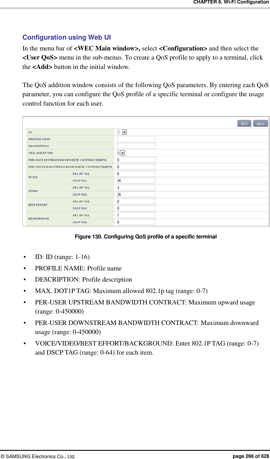
![CHAPTER 6. Wi-Fi Configuration © SAMSUNG Electronics Co., Ltd. page 267 of 628 6.2.4 Voice Optimization Configuration The APC configures an EDCA parameter value that is optimized for voice service to an AP in real-time. Configuration using CLI 1) Go to configure radio cvo mode to configure of CLI. APC# configure terminal APC/configure# [80211a|80211bg] cvo APC/configure/80211a/cvo# 2) Enable or disable the function. [no] enable 3) To check the configured information, use the ‘show 80211a cvo config’ command. Configuration using Web UI In the menu bar of <WEC Main window>, select <Configuration> and then select the <Radio> <802.11a/n> or <802.11b/g/n> <General> menu in the sub-menus. Figure 131. Configuring voice optimization To enable Controlled Voice Optimization (CVO), select Enable in the CONTROLLED VOICE OPTIMIZATION. To disable it, select Disable.](https://usermanual.wiki/Samsung-Electronics-Co/WEA463E.Part-1/User-Guide-2696662-Page-267.png)
![CHAPTER 6. Wi-Fi Configuration © SAMSUNG Electronics Co., Ltd. page 268 of 628 6.3 802.11h Configuration The APC supports the configuration and transmission power limitation for the Dynamic Frequency Selection (DFS) function in an AP. When the AP detects radar, an event is sent to the WEM and a detouring channel can be configured in the AP. Configuration using CLI For channel switching announcement related configuration and power constraint value configuration in an AP, execute the command as follows: 1) Go to configure 80211h configuration mode of CLI. APC# configure terminal APC/configure# 80211h APC/configure/80211h# 2) Configure the 802.11h information. channel-switch [MODE] [RESTRICTION] [SWITCH COUNT] Parameter Description MODE Whether the switching announcement function is enabled/disabled RESTRICTION Whether the channel packet transmission restriction mode is enabled (disable/enable) SWITCH COUNT Waiting time until channel switching announcement 3) Configure the transmission power of a wireless terminal. power-constraint [VALUE] Parameter Description VALUE Transmission power(0-31 dB) 4) To check the configuration information, use the ‘show 80211h configuration’ command.](https://usermanual.wiki/Samsung-Electronics-Co/WEA463E.Part-1/User-Guide-2696662-Page-268.png)
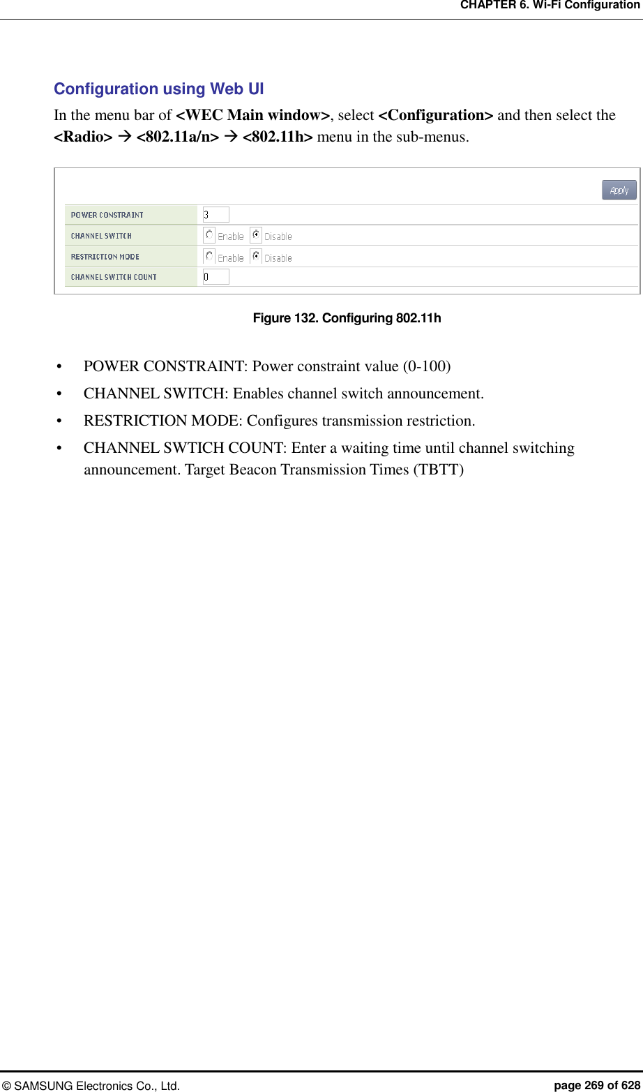
![CHAPTER 6. Wi-Fi Configuration © SAMSUNG Electronics Co., Ltd. page 270 of 628 6.4 Country Code You can use a country code to restrict the number of channels that can be used in an AP and the maximum transmission power of each channel. Configuration using CLI To configure the country code function, go to country mode first by executing the following command. APC# configure terminal APC/configure# country APC/configure/country# [Global Country Code Configuration] If you configure a global country code, the country code can be specified to all the connected APs at the same time. The command is shown below. set-global [COUNTRY_CODE] [VALUE] Parameter Description COUNTRY_CODE Country code to configure VALUE Environment configuration (both/outdoor/indoor/none) To check the configuration information, use the ‘show country global-config’ command. [AP Country Code Configuration] To configure a country code, execute the command as follows: set-ap [AP_ID] [COUNTRY_CODE] [VALUE] Parameter Description AP_ID AP ID (range: 1-500) COUNTRY_CODE Country code to configure VALUE Environment configuration (both/outdoor/indoor/none) To check the configuration information, use the ‘show country ap-config [AP_ID]’ command.](https://usermanual.wiki/Samsung-Electronics-Co/WEA463E.Part-1/User-Guide-2696662-Page-270.png)
![CHAPTER 6. Wi-Fi Configuration © SAMSUNG Electronics Co., Ltd. page 271 of 628 [Editing Country Code] You can add or delete an operation channel per country and change maximum transmission power per channel. The command used to add or delete a channel per country is shown below. add-channel [COUNTRY_CODE] [CHANNEL_NUMBER] [MAX_TX_POWER]: Adds a channel. del-channel [COUNTRY_CODE] [CHANNEL_NUMBER]: Deletes a channel. Parameter Description COUNTRY_CODE Country code to configure CHANNEL_NUMBER Channel to configure. MAX _TX_POWER Maximum transmission power per channel. The command used to change maximum transmission power value of a channel for a specific country code is shown below. max-tx-power [COUNTRY_CODE] [CHANNEL_NUMBER] [MAX_TX_POWER] Parameter Description COUNTRY_CODE Country code to configure CHANNEL_NUMBER Channel to configure. MAX _TX_POWER Maximum transmission power per channel. To check the configuration information, use the ‘show country information [COUNTRY_ CODE]’ command. Parameter Description COUNTRY_CODE Country code to configure](https://usermanual.wiki/Samsung-Electronics-Co/WEA463E.Part-1/User-Guide-2696662-Page-271.png)
![CHAPTER 6. Wi-Fi Configuration © SAMSUNG Electronics Co., Ltd. page 272 of 628 Configuration using Web UI In the menu bar of <WEC Main window>, select <Configuration> and then select the <Controller> <Country> menu in the sub-menus. Figure 133. Country code window (1) [Global Country Code Configuration] 1) Select a country in the DEFAULT COUNTRY drop-down list of Configured Country Code item. (Only an authenticated country code is supported.) 2) Select an environment in the DEFAULT ENVIRONMENT drop-down list. Both: The terminal operation environment includes all the environments. Outdoor: The terminal operation environment is outdoor. Indoor: The terminal operation environment is indoor. Non-country: A terminal is operating under non-country entity. 3) Click the <Apply> button to apply. [Editing Country Code] In the Edit Country Code item, you can add or delete an operation channel per country or change maximum transmission power per channel. 1) Select a country in the COUNTRY drop-down list of Edit Country Code item. (Only an authenticated country code is supported.) 2) Select a channel to add in the MAX TX POWER LEVEL (5 GHZ/2.4 GHZ) and enter maximum transmission power level (0-30). 3) In the MAX TX POWER LEVEL (5 GHZ/2.4 GHZ), unselect a channel to delete. 4) Click the <Apply> button to apply.](https://usermanual.wiki/Samsung-Electronics-Co/WEA463E.Part-1/User-Guide-2696662-Page-272.png)
![CHAPTER 6. Wi-Fi Configuration © SAMSUNG Electronics Co., Ltd. page 273 of 628 [AP Country Code Configuration] In the menu bar of <WEC Main window>, select <Configuration> and then select the <Access Points> <General> menu in the sub-menus. Figure 134. Country code window (2) After selecting COUNTRY and ENVIRONMENT, click the <Apply> button.](https://usermanual.wiki/Samsung-Electronics-Co/WEA463E.Part-1/User-Guide-2696662-Page-273.png)
![CHAPTER 7. WLAN Additional Services © SAMSUNG Electronics Co., Ltd. page 274 of 628 CHAPTER 7. WLAN Additional Services In this chapter, how to configure WLAN additional services such as wireless terminal management, spectrum analysis, Call Admission Control (CAC) and Radio Resource Management (RRM), etc. is described. 7.1 Managing Wireless Terminal 7.1.1 Information Retrieval Functions Configuration using CLI Using the following command, you can retrieve the information of a wireless terminal being serviced by the APC. show station summary: When you enter this command, the summary information of all the wireless terminals connected to the APC is retrieved. show station summary ap [AP_ID]: The information of wireless terminals of each AP is retrieved. show station summary bssid [BSSID_ID]: The information of wireless terminals of each BSSID is retrieved. show station summary wlan [WLAN_ID]: The information of wireless terminals of each WLAN is retrieved. show station detail [MAC_ADDRESS]: The detail information of a wireless terminal that has a specific MAC address is retrieved. show station stats ap-80211-stats [MAC_ADDRESS]: The WI-FI statistics information of a wireless terminal is retrieved. show station association history [MAC_ADDRESS]: The connection history of a wireless terminal is retrieved. show station stats debug all: The debug statistics information of a wireless terminal is retrieved. show station stats management_frame all: The debug statistics information of a wireless terminal is retrieved.](https://usermanual.wiki/Samsung-Electronics-Co/WEA463E.Part-1/User-Guide-2696662-Page-274.png)
![CHAPTER 7. WLAN Additional Services © SAMSUNG Electronics Co., Ltd. page 275 of 628 Configuration using Web UI In the menu bar of <WEC Main window>, select <Monitor> and then select the <Stations> menu in the sub-menus. The brief information of each station is displayed in the window. To check the detail information of a specific station, click the MAC information of the specific station in the Stations window list. Figure 135. Information viewing window 7.1.2 Connection History related Configuration You can configure maximum value for the connection history of a wireless terminal that will be managed in the APC. station number-of-assoc-tracking [COUNT] Parameter Description COUNT Maximum number of association tracking](https://usermanual.wiki/Samsung-Electronics-Co/WEA463E.Part-1/User-Guide-2696662-Page-275.png)
![CHAPTER 7. WLAN Additional Services © SAMSUNG Electronics Co., Ltd. page 276 of 628 7.2 Handover Management The handover releases a connection with an existing AP and connects to a new AP. It provides seamless wireless LAN connection to a wireless terminal. The APC provides both 802.11 standard handover and Samsung’s unique AirMove (Network Controlled Handover) handover. 7.2.1 Connection History Information Use the ‘show station association history [MAC_ADDRESS]’ command to check the handover history information of a specific wireless terminal connected to the APC. 7.2.2 AirMove Configuration Unlike the 802.11 standard handover where a wireless terminal performs the handover function by itself, the AirMove handover is performed by the collaboration between wireless terminals compatible with the APC. Therefore, the packet loss or handover time is optimized. Some Samsung smartphones such as Galaxy S2 or S3, etc. provide the AirMove function. Configuration using CLI To configure the AirMove related function, execute the following command to go to the handover configuration mode. WEC8500# configure terminal WEC8500/configure# handover [Handover Option Configuration] handover [OPTION] [OPTION_DETAIL] AirMove Configuration Item Description operation mode Operation mode configuration - OPTION: opmode - OPTION_DETAIL: Each mode (VoIP/STA) buffered-forwarding mode Configures whether to use the buffered forwarding function. - OPTION: fwd-buffering - OPTION_DETAIL: Enable/Disable decision delta Configures the threshold of RSSI difference between a serving AP and a target AP. - OPTION: decision-delta - OPTION_DETAIL: Threshold (dBm) scan time on channel Configures scanning time of a wireless terminal per channel. - option: scan-time-channel - OPTION_DETAIL: Time (ms)](https://usermanual.wiki/Samsung-Electronics-Co/WEA463E.Part-1/User-Guide-2696662-Page-276.png)
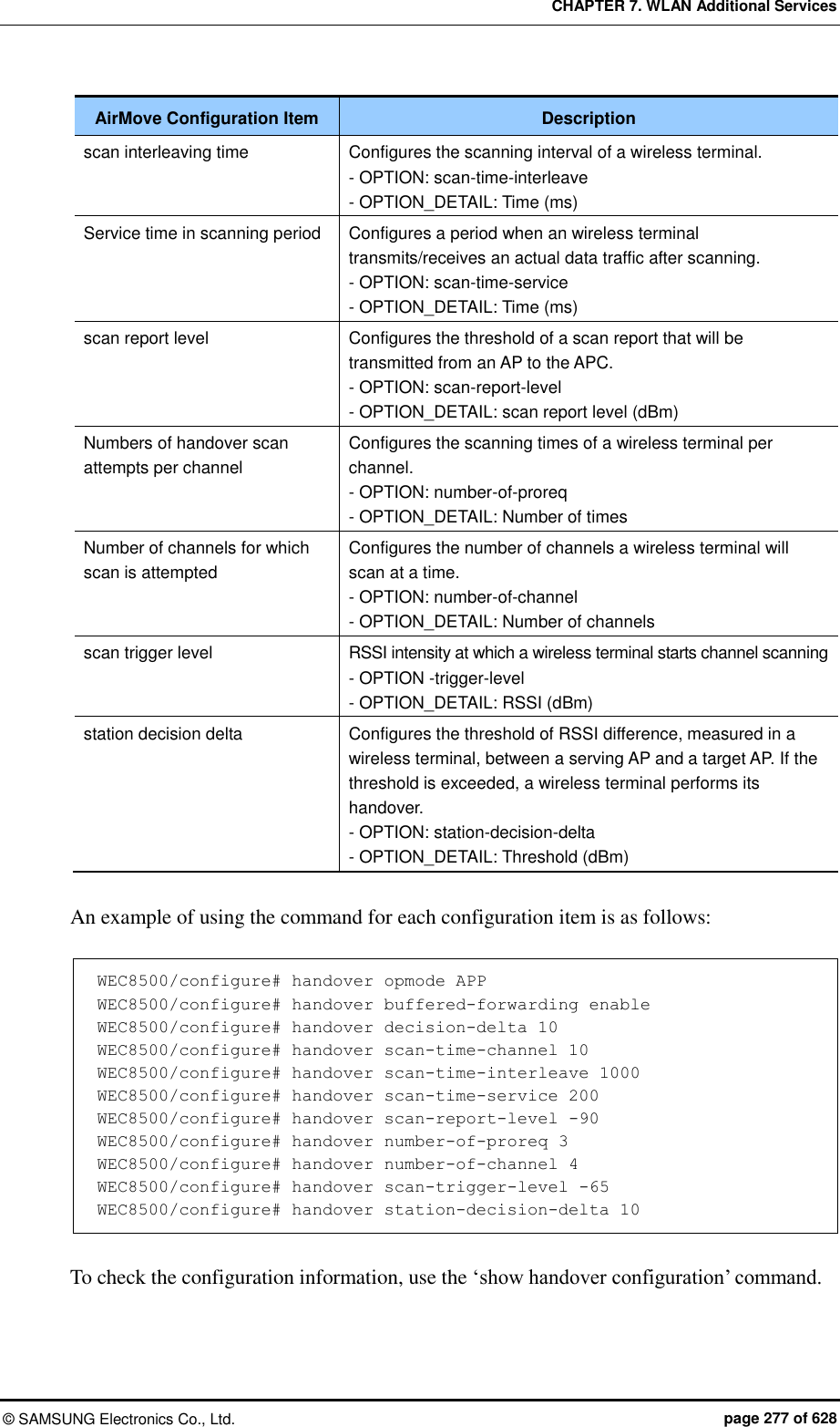
![CHAPTER 7. WLAN Additional Services © SAMSUNG Electronics Co., Ltd. page 278 of 628 [AirMove Enable/Disable Configuration] The AirMove is enabled by default, so use the following command to disable it. no handover mode NCHO To check the configuration information, use the ‘show handover configuration’ command. Configuration using Web UI In the menu bar of <WEC Main window>, select <Configuration> and then select the <Mobility Management> <Handover> menu in the sub-menus. Figure 136. Handover window You can enable or disable the intra handover function by selecting Enable/Disable in the INTER APC HAND-OVER item. After configuring a value, click the <Apply> button to apply. 7.2.3 Inter APC Handover Configuration The Inter APC handover is a technology that supports handover among several APC systems. Depending on network configuration, the Inter APC L3 handover and Inter APC L2 handover services are provided. By using the clustering service, you can configure several APC systems into a single group. Configures whether to use the Inter APC handover. The default value of Inter APC handover is not configured. handover inter-apc enable To check the configuration information, use the ‘show handover configuration’ command.](https://usermanual.wiki/Samsung-Electronics-Co/WEA463E.Part-1/User-Guide-2696662-Page-278.png)
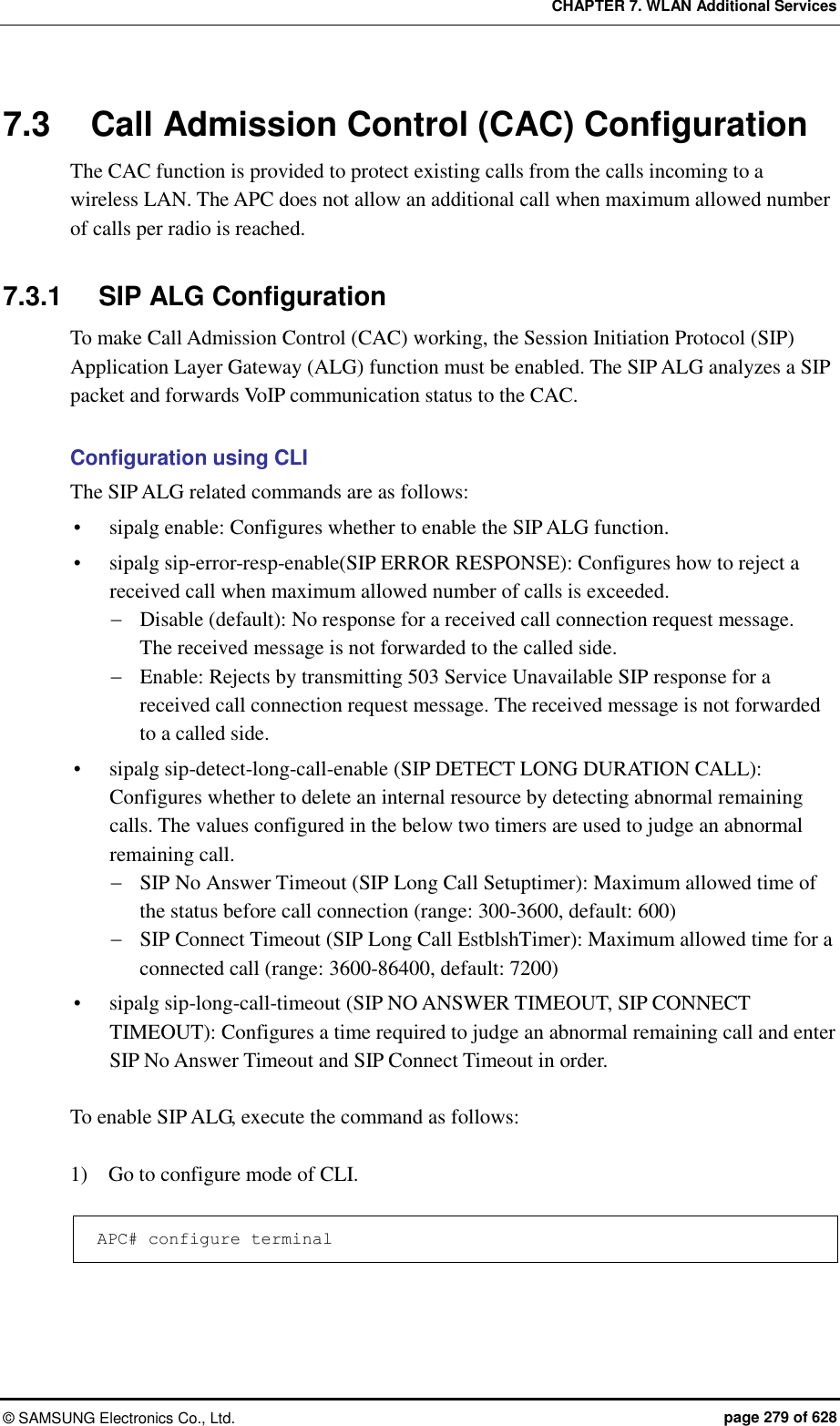
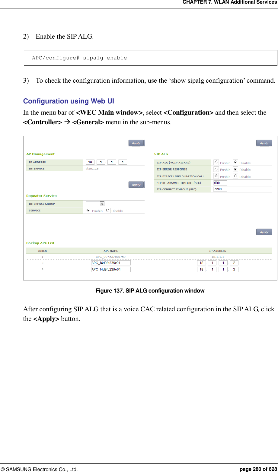
![CHAPTER 7. WLAN Additional Services © SAMSUNG Electronics Co., Ltd. page 281 of 628 7.3.2 Voice CAC Configuration To protect existing calls, the voice CAC function configures maximum allowed number of calls and rejects any call request when the maximum number is exceeded. You can configure the number of marginal voice calls for handover. Configuration using CLI For voice CAC configuration, execute the command as follows: 1) Go to configure voice CAC mode of a wireless section of CLI. APC# configure terminal APC/configure# [80211a/80211bg] cac voice APC/configure/80211a/cac/voice# 2) Enable or disable the voice CAC function. acm [MODE] Parameter Description MODE Enables or disables the voice CAC function - enable: Enable - disable: Disable 3) Configure maximum allowed number of voice calls. max-calls [VALUE] Parameter Description VALUE Maximum allowed number of voice calls. 4) Configure the number of marginal voice calls considering the handover. reserved-ho-calls [VALUE] Parameter Description VALUE Number of marginal voice calls considering the handover 5) To check the configured voice CAC information, use the ‘show [80211a | 80211bg] cac voice configuration’ command.](https://usermanual.wiki/Samsung-Electronics-Co/WEA463E.Part-1/User-Guide-2696662-Page-281.png)
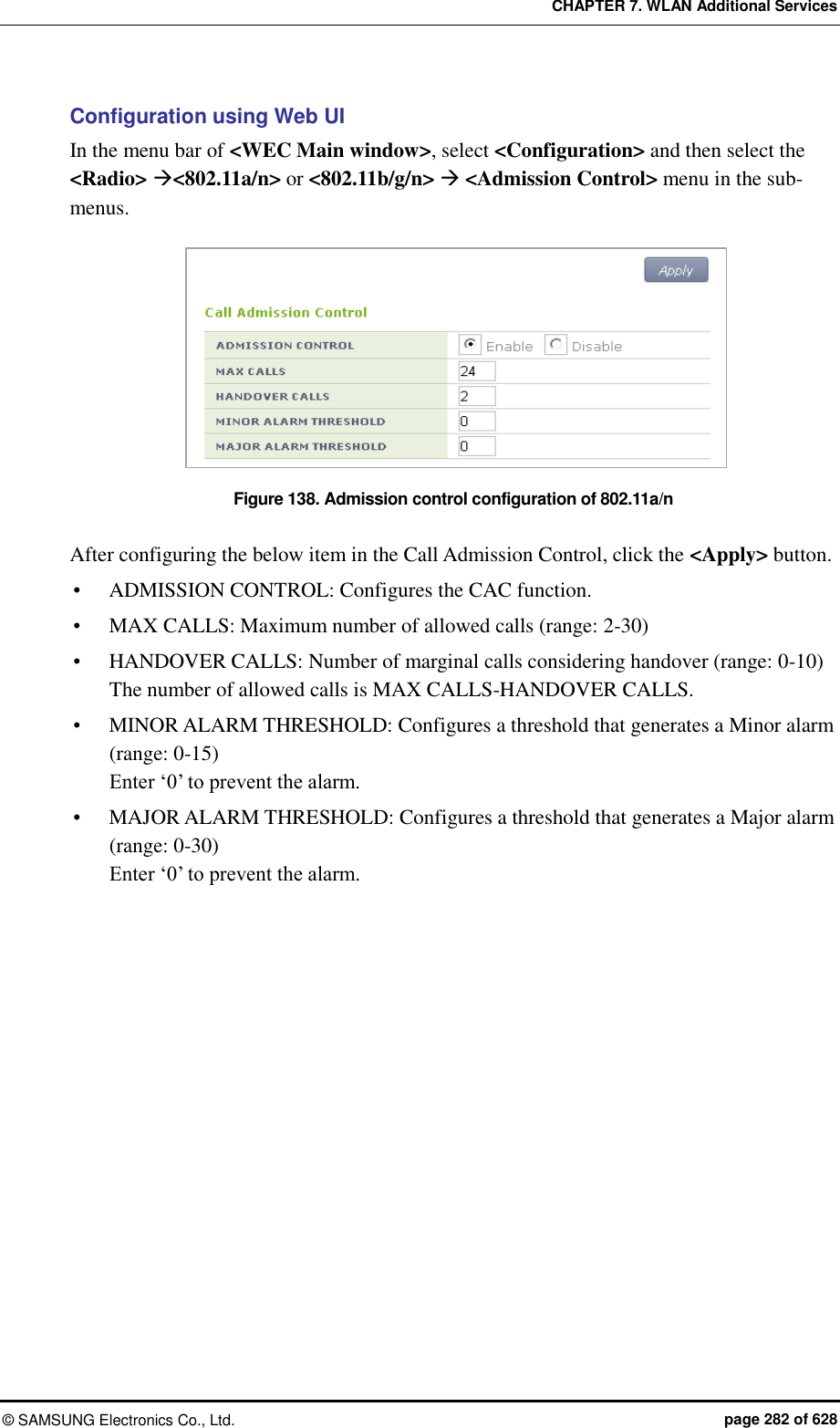
![CHAPTER 7. WLAN Additional Services © SAMSUNG Electronics Co., Ltd. page 283 of 628 7.3.3 Video CAC Configuration To protect existing video calls, the video CAC function configures the maximum allowed number of video calls and rejects any call request when the maximum number is exceeded. You can configure the number of marginal calls for handover. Configuration using CLI For video CAC configuration, execute the command as follows: 1) Go to configure video CAC mode of a wireless section of CLI. APC# configure terminal APC/configure# [80211a/80211bg] cac video APC/configure/80211a/cac/video# 2) Enable or disable the video CAC function. acm [MODE] Parameter Description Mode Enables or disables the CAC function - enable: Enable - disable: Disable 3) Select a video CAC method. method [method] Parameter Description method Select a video CAC method (static/chan_util) - static: Based on video calls - chan_util: Based on channel usage 4) Configure the maximum allowed number of calls. max-calls [VALUE] Parameter Description VALUE Maximum allowed number of video calls 5) Configure the number of marginal calls with consideration for handover. reserved-ho-calls [VALUE] Parameter Description VALUE Number of marginal calls with consideration for handover](https://usermanual.wiki/Samsung-Electronics-Co/WEA463E.Part-1/User-Guide-2696662-Page-283.png)
![CHAPTER 7. WLAN Additional Services © SAMSUNG Electronics Co., Ltd. page 284 of 628 6) Configure the maximum allowed usage of channels. max-chan-util [VALUE] Parameter Description VALUE Maximum allowed usage of channels 7) Configure the usage of marginal channels with consideration for handover. reserved-ho-chan-util [VALUE] Parameter Description VALUE Usage of marginal channels with consideration for handover 8) You can view the video CAC information you configured by executing the ‘show [80211a | 80211bg] cac video configuration’ command. Configuration using Web UI From the menu bar of <WEC Main Window>, select <Configuration> and then select <Radio> <802.11a/n> or <802.11b/g/n> <Admission Control> in the submenus. Figure 139. 802.11a/n Admission Control Configuration Window After configuring the items below in the Call Admission Control, click the <Apply> button. ADMISSION CONTROL: Configure the video CAC function METHOD: Select a video CAC method (static/chan_util) MAX CALLS: Maximum allowed number of calls (range: 2-30) HANDOVER CALLS: Number of marginal calls with consideration for handover (range: 0-8) The maximum allowed number of calls becomes MAX CALLS-HANDOVER CALLS. MAX CHANNEL UTILIZATION (%): Maximum allowed usage of channels (range: 5-85) HANDOVER CHANNEL UTILIZATION (%): Usage of marginal channels with consideration for handover (range: 0-25)](https://usermanual.wiki/Samsung-Electronics-Co/WEA463E.Part-1/User-Guide-2696662-Page-284.png)
![CHAPTER 7. WLAN Additional Services © SAMSUNG Electronics Co., Ltd. page 285 of 628 7.4 Radio Resource Management (RRM) RRM performs automatic setup function for AP’s channel and Tx Power. RRM is functionally divided into Dynamic Channel Selection (DCS), Dynamic Power control (DPC), and Coverage Hole Detection and Control (CHDC). The DCS automatically sets the channels of the APs. The DPC DCS automatically sets the Tx Power of the AP. The CHDC adjusts the Tx Power when Coverage Hole occurs. 7.4.1 RRM Configuration This section describes the settings for using the RRM function and the cluster configuration. Configuration using CLI To configure each function, execute the command as follows: 1) Go to configure rrm configuration mode of CLI. WEC8500# configure terminal WEC8500/configure# rrm 2) Enable RRM. The ‘no’ parameter is used to disable RRM. DCS, DPC and CHDC, which are functions of RRM, can run only if the RRM is enabled. WEC8500/configure/rrm# enable 3) In the cluster environment, set the same RF Group Name to all the connected APCs. A name must consist of up to 15 characters. WEC8500/configure/rrm# rf-group-name [Name] 4) Configure priorities between the neighbor list of each Wlan. Go to the wireless section the configuration of which you want to change and then enter neighbor-list setup mode. You can select between rssi and handover, and the default value is rssi. WEC8500/configure/rrm# 80211a WEC8500/configure/rrm/80211a# neighbor-list WEC8500/configure/rrm/80211a/neighbor-list# wlan-neighbor-priority rssi/handover 5) To check the configured information, use the ‘show rrm config-summary’ command.](https://usermanual.wiki/Samsung-Electronics-Co/WEA463E.Part-1/User-Guide-2696662-Page-285.png)
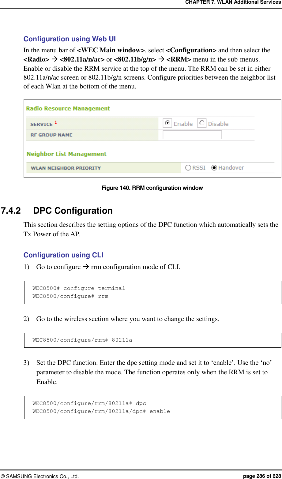
![CHAPTER 7. WLAN Additional Services © SAMSUNG Electronics Co., Ltd. page 287 of 628 4) Execute the following command to change the Received Signal Strength Indication (RSSI) threshold for neighbor AP. The default value is -70 (dBm). WEC8500/configure/rrm/80211a/dpc# rssi-threshold [value] 5) If you need to change the RSSI threshold for the station, execute the following command. The default value is -70 (dBm). This parameter is used only in the DCS-DPC joint algorithm. WEC8500/configure/rrm/80211a/dpc# rssi-threshold-for-stn [value] 6) Execute the following command to change the execution interval. The default value is 600 (seconds). WEC8500/configure/rrm/80211a/dpc# periodic-interval [value] 7) Execute the following command to change the Tx Power range which is automatically set by DPC. The default minimum is 16 for 80211a and 12 for 80211b. The default maximum is 20 for both 80211a and 80211b. WEC8500/configure/rrm/80211a/dpc# txPower min [value] max [value] 8) Check the settings using the ‘show rrm config-summary’ command. Configuration using Web UI In the menu bar of <WEC Main window>, select <Configuration> and then select the <Radio> <802.11a/n/ac> or <802.11b/g/n> <RRM> menu in the sub-menus. Enable or disable the DPC in the SERVICE field in Dynamic TX Power Control. Figure 141. DPC settings](https://usermanual.wiki/Samsung-Electronics-Co/WEA463E.Part-1/User-Guide-2696662-Page-287.png)
![CHAPTER 7. WLAN Additional Services © SAMSUNG Electronics Co., Ltd. page 288 of 628 7.4.3 DCS Configuration This section describes the setting options of the DCS function which automatically sets the channel of the AP. Configuration using CLI 1) Go to configure rrm configuration mode of CLI. WEC8500# configure terminal WEC8500/configure# rrm 2) Go to the wireless section where you want to change the settings. WEC8500/configure/rrm# 80211a 3) Set the DCS function. Enter the dcs setting mode and set it to ‘enable’. Use the ‘no’ parameter to disable the mode. The function operates only when the RRM is set to Enable. WEC8500/configure/rrm/80211a# dcs WEC8500/configure/rrm/80211a/dcs# enable 4) Configure whether to apply the DCS-DPC joint algorithm. If the ‘no’ parameter is selected, the configuration is cleared. WEC8500/configure/rrm/80211a/dcs# joint-algo-enable 5) Execute the following command to change the execution interval. The default value is 120 (seconds). WEC8500/configure/rrm/80211a/dcs# periodic-interval [value] 6) Execute the following command to change the Channel Utilization threshold. The default value is 80 (%). WEC8500/configure/rrm/80211a/dcs# channel-utilization-threshold [value] 7) Execute the following command to change the My Utilization threshold. The default is 10 (%) for 802.11a and 40 (%) for 802.11b. WEC8500/configure/rrm/80211a/dcs# my-utilization-threshold [value]](https://usermanual.wiki/Samsung-Electronics-Co/WEA463E.Part-1/User-Guide-2696662-Page-288.png)
![CHAPTER 7. WLAN Additional Services © SAMSUNG Electronics Co., Ltd. page 289 of 628 8) Execute the following command to set the anchor time. The default value is start time 4, end time 5. If both start time and end time are set to the same time, Anchor Run function is disabled. WEC8500/configure/rrm/80211a/dcs# anchor-time start [value] end [value] 9) Execute the following command to change the channels that is automatically set by the DCS. Use the ‘no’ parameter to disable the mode. WEC8500/configure/rrm/80211a/dcs# channel [value] 10) Execute the following command to use the Delayed Channel Change function. To disable the configuration, enter the ‘no’ parameter. The default is Disable. The Delayed Channel Change function delays channel change instead of changing it immediately when a channel becomes busy due to channel utilization. If the anchor time is not configured, the default value is used at 4 o’clock. WEC8500/configure/rrm/80211a/dcs# delayed-channel-change 11) To use the Aware Option function, execute the following command. To disable the configuration, enter the ‘no’ parameter. The Aware Option does not change a channel if there is a specific condition. Therefore, three functions are provided based on whether there is a voice, the association of a station, or traffic in a station. The default is that only the Voice Aware function is enabled. The Station Aware function specifies the number of stations at the same time. WEC8500/configure/rrm/80211a/dcs# aware-option voice WEC8500/configure/rrm/80211a/dcs# aware-option station [station count] WEC8500/configure/rrm/80211a/dcs# aware-option traffic 12) Check the settings using the ‘show rrm config-summary’ command.](https://usermanual.wiki/Samsung-Electronics-Co/WEA463E.Part-1/User-Guide-2696662-Page-289.png)
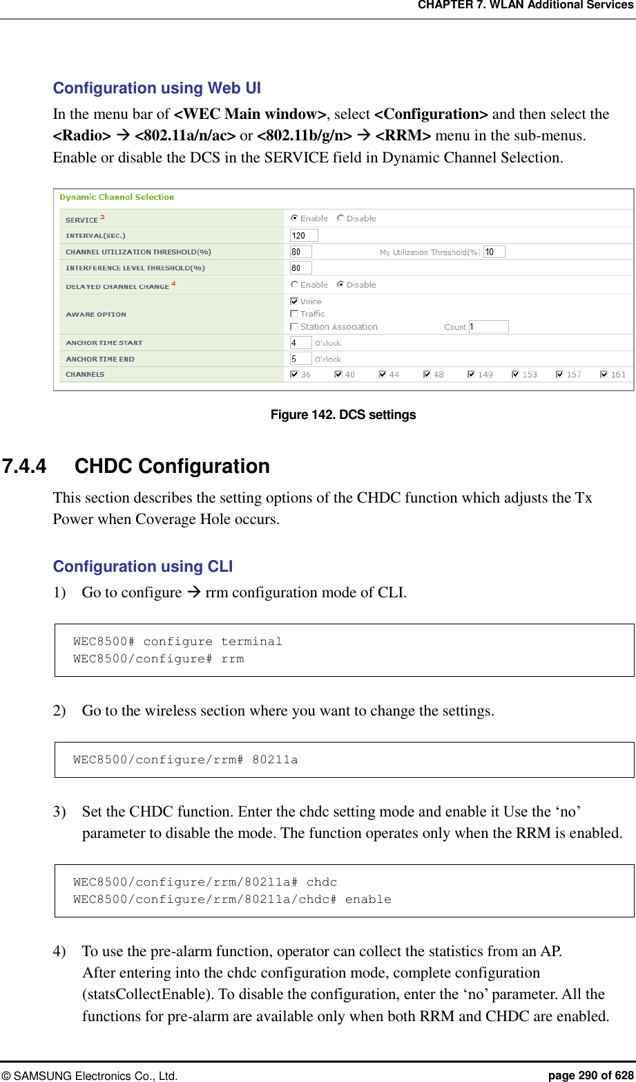
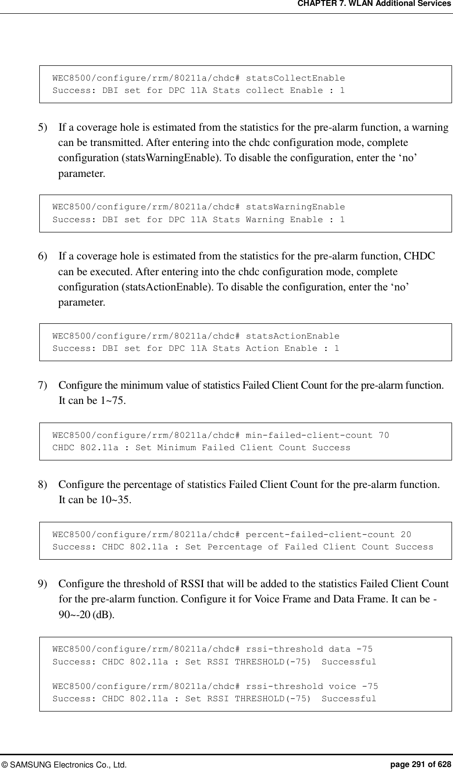
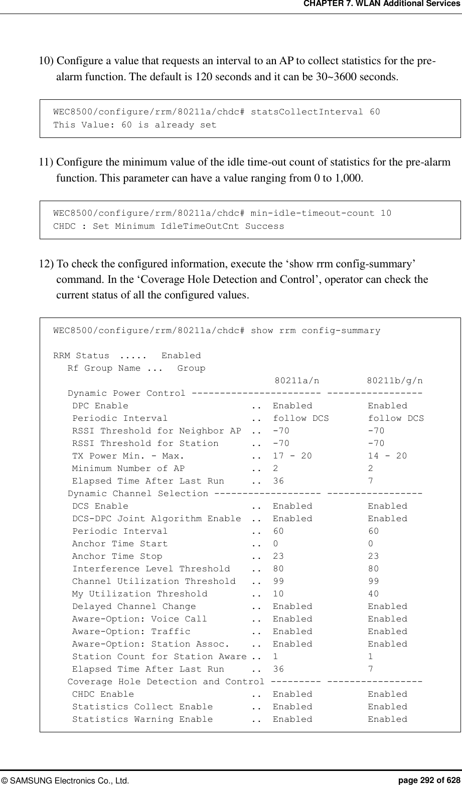
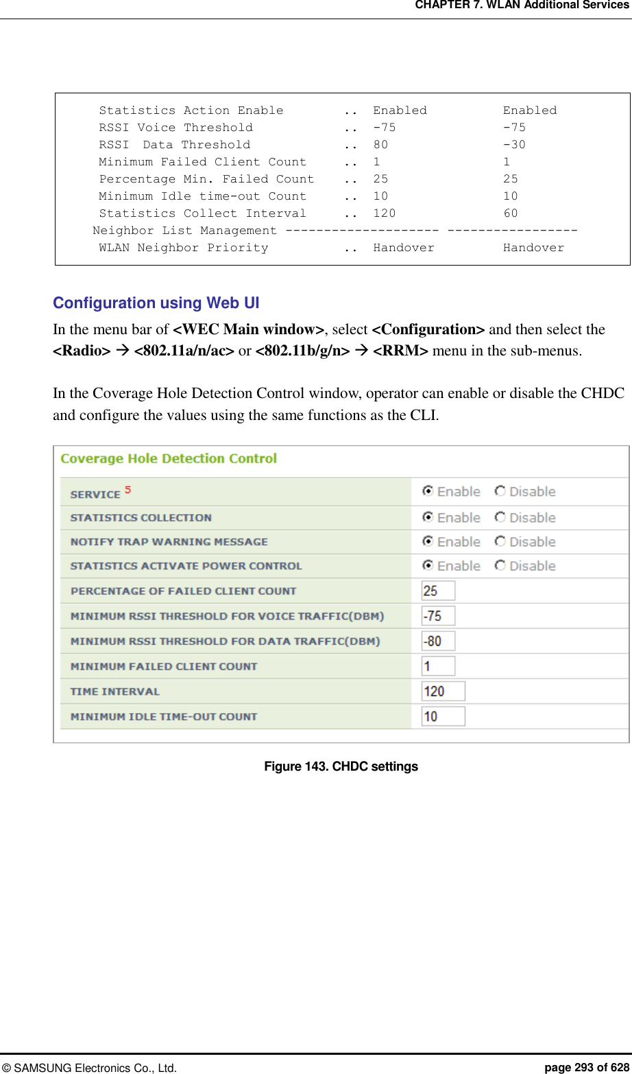
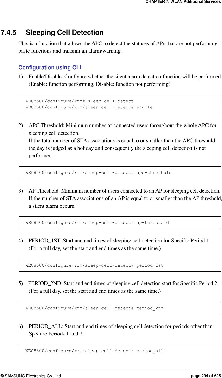
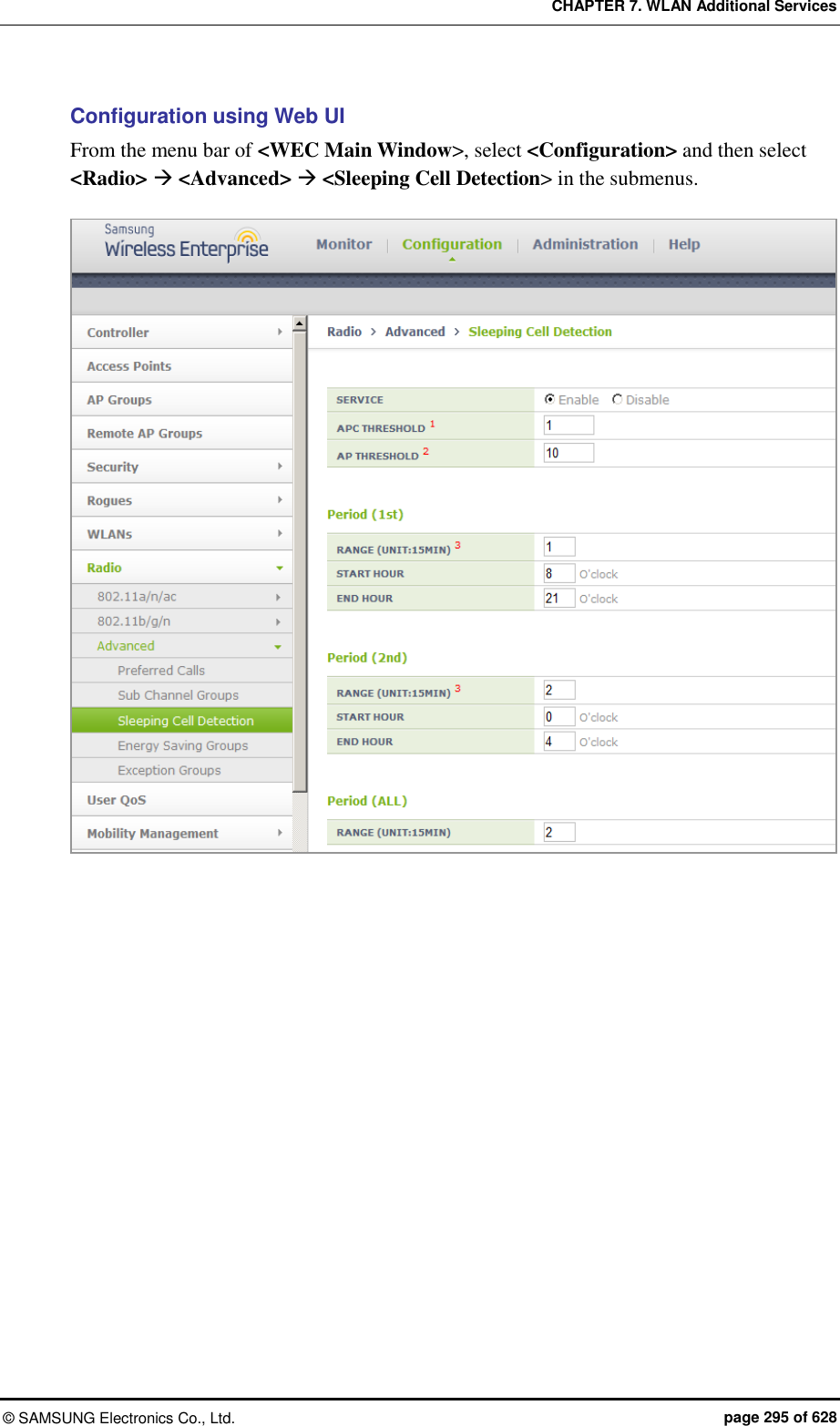
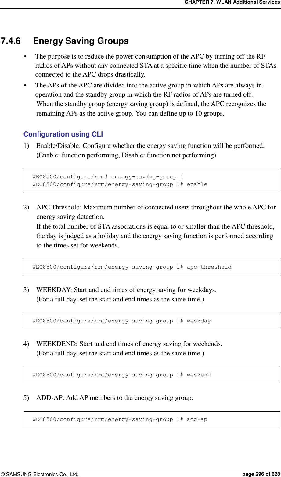
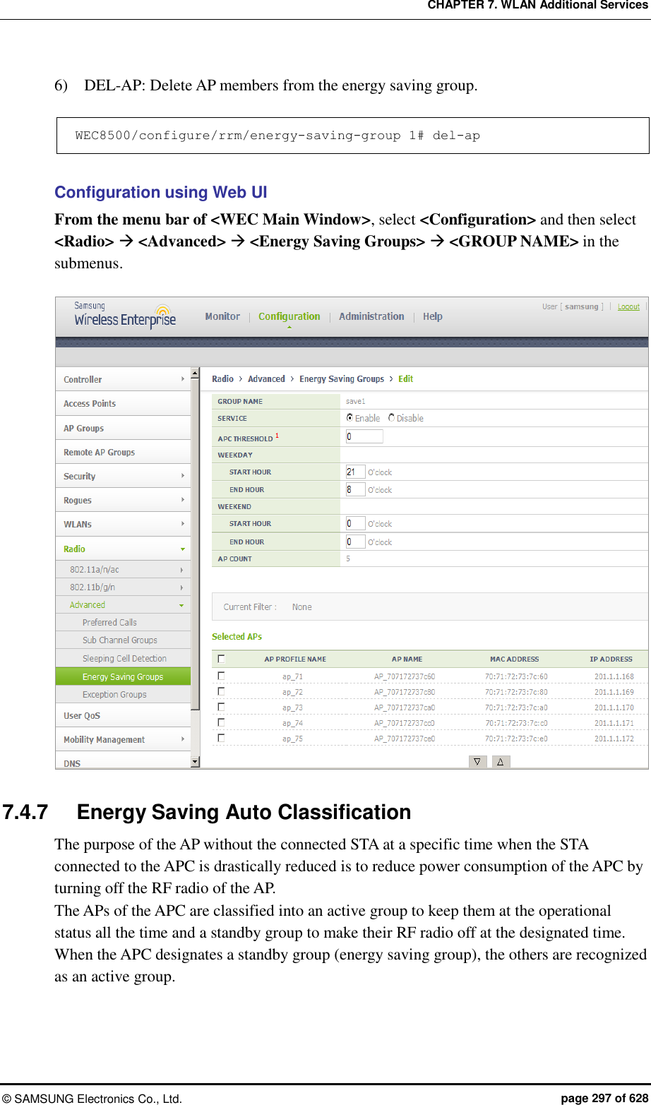
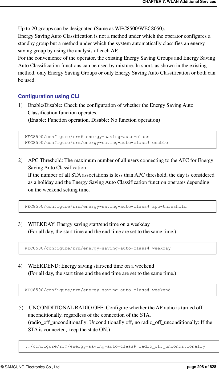
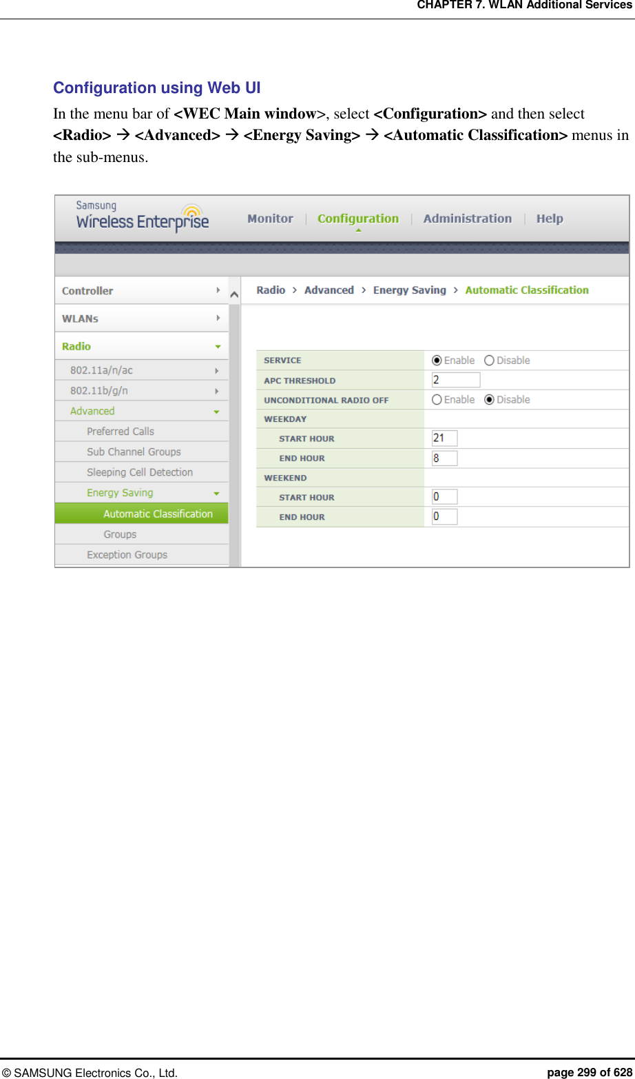
![CHAPTER 7. WLAN Additional Services © SAMSUNG Electronics Co., Ltd. page 300 of 628 7.5 Location Tracking The APC tracks the location information of several terminals in a wireless LAN network based on the wireless data collected from W-EP wireless LAN APs. To configure the location tracking function, execute the command as follows: 1) Go to configure locationtrack configuration mode of CLI. WEC8500# configure terminal WEC8500/configure # locationtrack WEC8500/configure/locationtrack # 2) Configure the location tracking function. WEC8500/configure/locationtrack # enable 3) To check the configured information, execute the ‘show locationtrack config’ command. WEC8500/configure/locationtrack # show locationtrack config Location tracking enable....: Enabled Algorithm type..............: 4 Expiry date of history files: 0 4) Configure the MAC address of a wireless terminal for which the tracking function will be executed. station [MAC_ADDRESS] 5) To check the location information of a wireless terminal to track, execute the ‘show locationtrack station’ command. WEC8500/configure/locationtrack # show locationtrack station No. stationId station_MAC_Addr ap_MAC_Addr (staX,staY) lastTime(+) ---- --------- ----------------- ----------------- ----------------- -------------------- 1 1 f4:d9:fb:34:20:60 f4:d9:fb:34:20:60 (2432,1947) 0(1374022070)](https://usermanual.wiki/Samsung-Electronics-Co/WEA463E.Part-1/User-Guide-2696662-Page-300.png)
![CHAPTER 7. WLAN Additional Services © SAMSUNG Electronics Co., Ltd. page 301 of 628 7.6 Spectrum Analysis A non-802.11 device such as microwave oven, bluetooth, or Closed Circuit Television (CCTV), etc. deteriorates data transmitting/receiving performance because it causes interference in a wireless LAN environment. As a function that measures surrounding interference, the spectrum analysis analyzes wireless or Radio Frequency (RF) signals to resolve interference problem instantly. 7.6.1 Retrieving Spectrum Analysis Data The spectrum analysis function of APC provides the following data. Sample report: Wireless capture data converted into Fast Fourier Transform (FFT) Duty cycle report: Channel utilization rate Interference report: Interference signal information The FFT report provides the information of an AP and maximum 13 available channels and also maximum/minimum values of Received Signal Strength Indicator (RSSI) for each channel. The duty cycle report provides AP information and affected channel information. In addition, it provides duty cycle transmission data that indirectly provides channel utilization rate. The interference report provides AP information, affected channel, or configuration information of an interferer and also interference information (RSSI or maximum/minimum frequency of an interference signal) in real-time. Configuration using CLI By using the following command, you can check each data. show spectrum-analysis report [DATA] ap [AP_ID] Parameter Description DATA Spectrum analysis data type (sample/duty_cycle/interference) AP_ID AP ID (range: 1-500) An example of command execution and its execution result are as follows: FFT report APC# show spectrum-analysis report sample ap 1 FFT (Fast Fourier Transform) Reporting Enabled AP ID 1 Description: MAC Address...................................... 00:11:22:33:44:55 Name............................................. AP_ 01122334455 IP Address....................................... 100.100.100.220 Mode............................................. General](https://usermanual.wiki/Samsung-Electronics-Co/WEA463E.Part-1/User-Guide-2696662-Page-301.png)
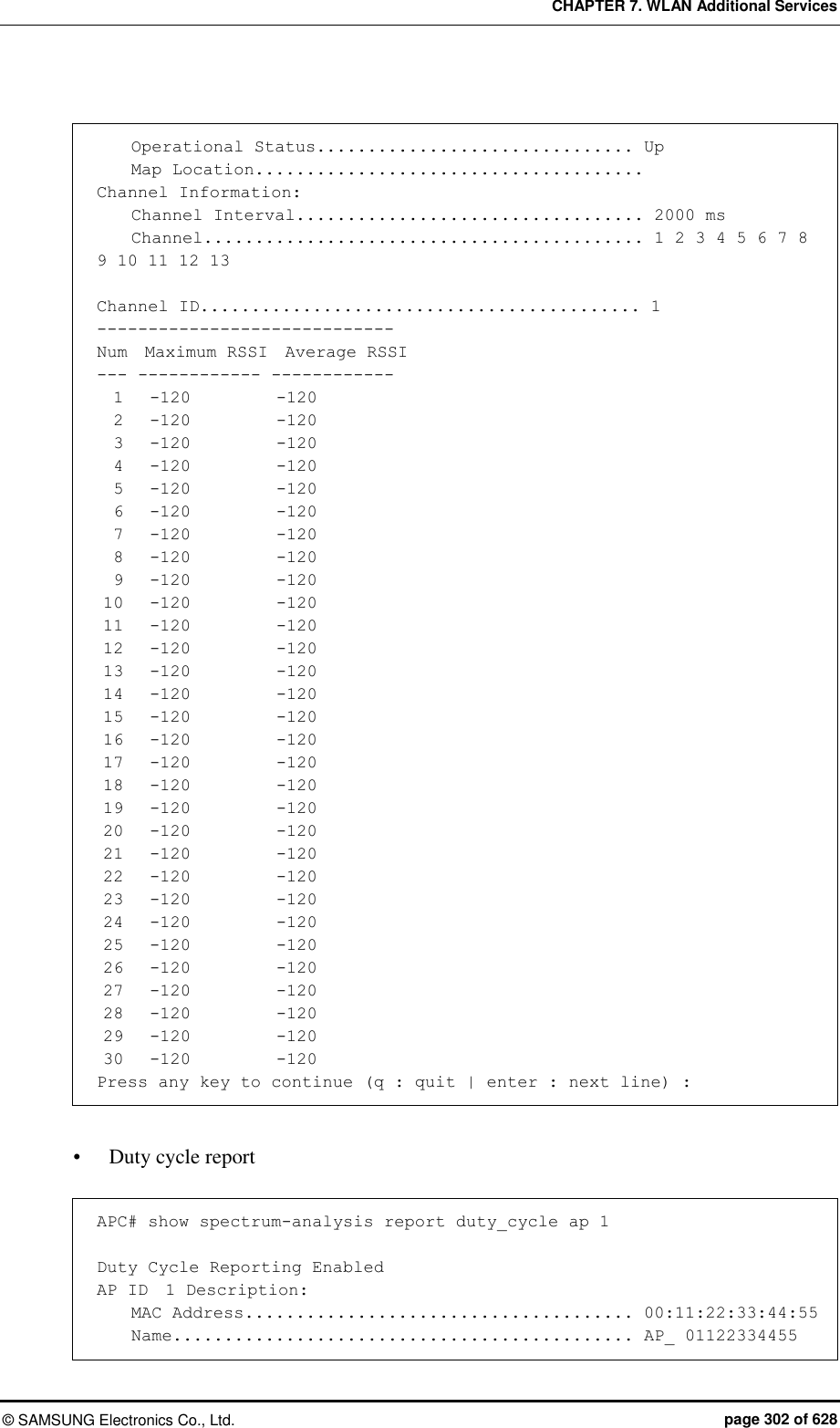
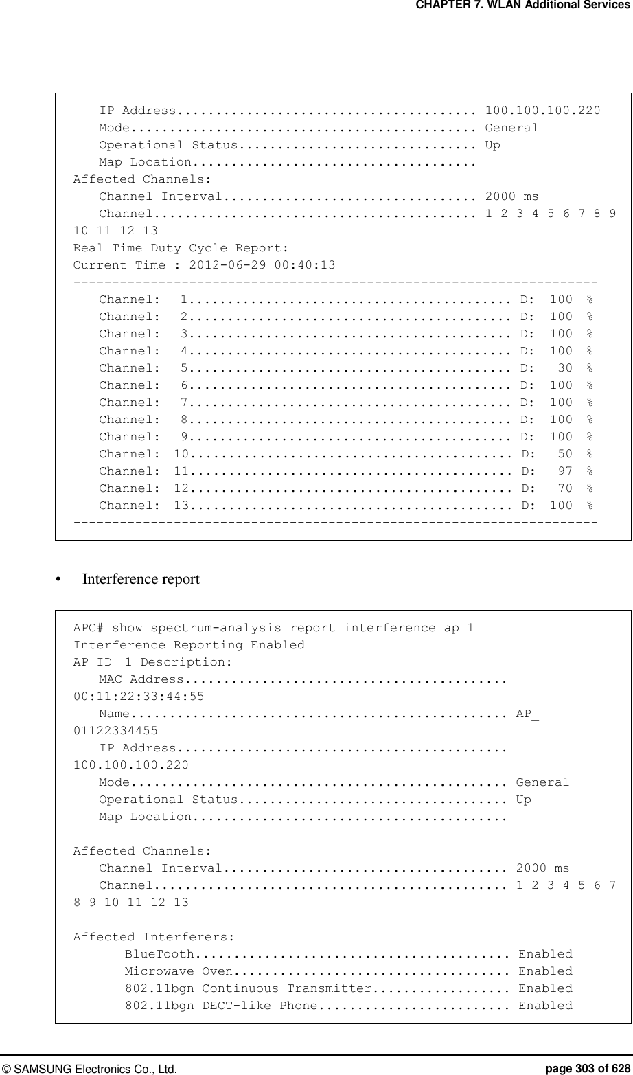
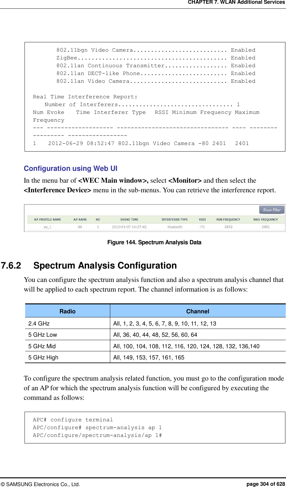
![CHAPTER 7. WLAN Additional Services © SAMSUNG Electronics Co., Ltd. page 305 of 628 [Enable/Disable Spectrum] The command that enables or disables the spectrum analysis function is shown below. service [MODE] Parameter Description MODE Enables or disables spectrum analysis - enable: Enable (default) - disable: Disable [Spectrum Analysis Report Configuration] The command used to enable or disable each spectrum analysis data item is shown below. configuration-request [DATA] [MODE] Parameter Description DATA Type of a report to configure (sample/duty-cycle/interference) - sample: FFT report (default: disabled) - duty-cycle: Duty cycle report (default: disabled) - interference: Interference report (default: enable) MODE Enables or disables each report function. - enable: Enable - disable: Disable [Channel Report Interval Configuration] The command is shown below. channel-interval [INTERVAL] Parameter Description INTERVAL Channel report interval (range: 1000-60000 ms, default: 1000) [Changing Channel] By using the following command, you can change a channel for which the spectrum analysis will be executed. (The default is ‘All’ channels.) dot11b: 2.4 GHz wireless bandwidth dot11aLow: 5 GHz low wireless bandwidth dot11aMid: 5 GHz mid wireless bandwidth dot11aHigh: 5 GHz high wireless bandwidth](https://usermanual.wiki/Samsung-Electronics-Co/WEA463E.Part-1/User-Guide-2696662-Page-305.png)
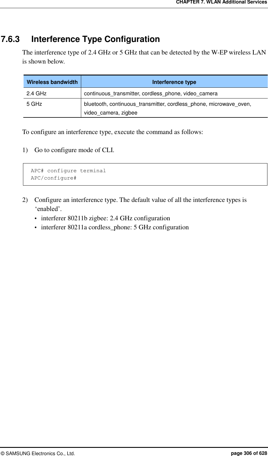
![CHAPTER 7. WLAN Additional Services © SAMSUNG Electronics Co., Ltd. page 307 of 628 7.7 Controlling Usage per User A wireless terminal can control traffic usage per user by receiving a QoS profile that specifies traffic usage (bandwidth) from the RADIUS server at the authentication stage. You can configure upward and downward usage per wireless terminal. Configuration using CLI The procedure of configuring a usage to a profile is as follows: 1) Go to configure mode of CLI. APC# configure terminal 2) Create a QoS profile. APC/configure# qos [PROFILE_NAME] APC/configure/qos samsung# Parameter Description PROFILE_NAME Name of a QoS profile to create 3) Configure the downward usage in kbps. bw-contract-downstream [VALUE] Parameter Description VALUE Downward usage 4) Configure the upward usage in kbps. bw-contract-upstream [VALUE] Parameter Description VALUE Upward usage 5) To check the configured profile information, use the ‘show qos profile’ command.](https://usermanual.wiki/Samsung-Electronics-Co/WEA463E.Part-1/User-Guide-2696662-Page-307.png)

![CHAPTER 7. WLAN Additional Services © SAMSUNG Electronics Co., Ltd. page 309 of 628 7.8 Remote Packet Capture APC can capture a packet exchanged between the wireless terminals on a remote PC in real-time by using the remote packet capture protocol. To configure the remote packet capture function, you must go to the pcap mode by executing the command as follows: APC# configure terminal APC/configure# pcap Configuring the MAC address of a wireless terminal Configure the MAC address of a wireless terminal whose packets will be captured. APC/configure/pcap# config-filter APC/configure/pcap/config-filter# station-mac [MAC_ADDRESS] APC/configure/pcap/config-filter# enable-station-mac [INDEX] Parameter Description MAC_ADDRESS MAC address (11:22:33:44:55:66 format) INDEX Index number of MAC address (range: 1-10) Configuring AP MAC address Configure the MAC address of an AP whose packets will be captured. APC/configure/pcap# config-filter APC/configure/pcap/config-filter# ap-mac [MAC_ADDRESS] APC/configure/pcap/config-filter# enable-ap-mac [INDEX] Parameter Description MAC_ADDRESS MAC address (11:22:33:44:55:66 format) INDEX Index number of MAC address (range: 1-10) Configuring Filtering Mode Capture target can be specified by configuring the filtering mode APC/configure/pcap# filtering-mode [FILTERING MODE] Parameter Description FILTERING MODE Filtering mode - station-only: Use only the configured station MAC information. - ap-only: Use only the configured AP MAC information.](https://usermanual.wiki/Samsung-Electronics-Co/WEA463E.Part-1/User-Guide-2696662-Page-309.png)
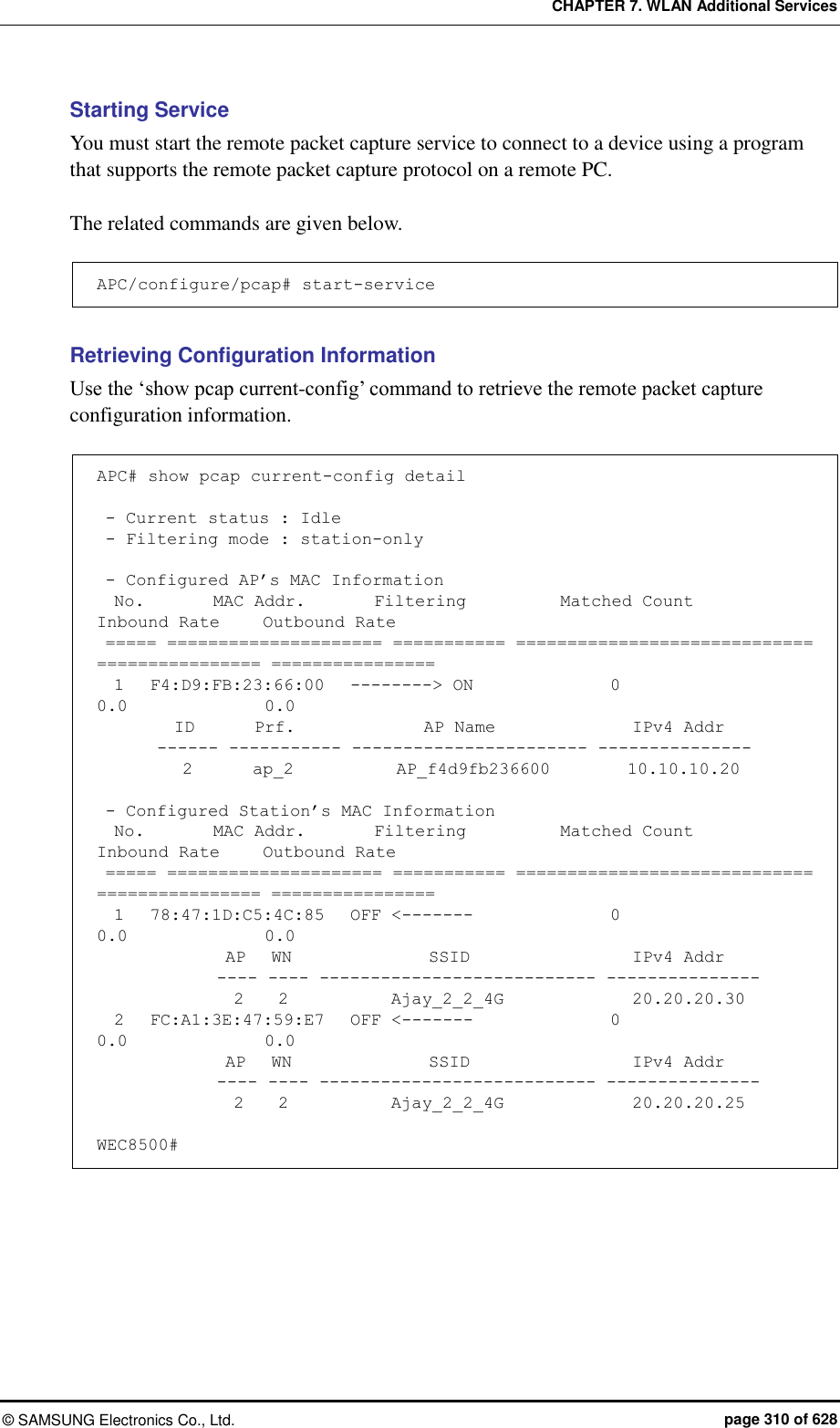
![CHAPTER 7. WLAN Additional Services © SAMSUNG Electronics Co., Ltd. page 311 of 628 7.9 Clustering The clustering function comprehensively manages several APC systems in a single wireless LAN when several APC systems are used to manage a wireless LAN that cannot be managed by a single APC. The inter-APC handover function is provided by using clustering. In other words, it can provide the handover function between wireless LANs managed by different APC systems. However, if a model is different, it is not interoperated through clustering. Configuration using CLI [Cluster Setting] To use the clustering function, you must configure each APC according to the following procedure. Maximum 12 WEC8500 can be grouped in a cluster. Maximum 2 WEC8050 can be grouped in a cluster. 1) Go to configure mode of CLI. WEC8500# configure terminal WEC8500/configure# 2) Set the interval and the number of retries to transmit the Keep-alive messages between APCs in the cluster. cluster keep-alive-interval [INTERVAL] cluster keep-alive-retry-count [RETRY_COUNT] Parameter Description INTERVAL Interval to transmit the Keep-alive message (Unit: s, range: 1-30, default: 10) RETRY_COUNT Maximum number of the transmission retries when there is no response to the Keep-alive message (range: 3-20, default: 3) 3) Enable the cluster cluster enable: Enable no cluster enable: Disable 4) To check the configuration information, use the ‘show cluster config’ command. WEC8500# show cluster config ======================================================== CLUSTER CONFIGURATION INFORMATION ======================================================== KEEP-ALIVE-INTERVAL : 10 KEEP-ALIVE-RETRY-COUNT : 3](https://usermanual.wiki/Samsung-Electronics-Co/WEA463E.Part-1/User-Guide-2696662-Page-311.png)
![CHAPTER 7. WLAN Additional Services © SAMSUNG Electronics Co., Ltd. page 312 of 628 ENABLE : YES OWN-APC-INDEX : 1 ======================================================== [Adding APC to APC List] To add an APC to the cluster, the APC must be added to the APC list first. APC information is automatically added to the APC list. 1) Go to apc-list configure mode of CLI. WEC8500# configure terminal WEC8500/configure# apc apc-list WEC8500/configure/apc/apc-list# 2) Add the APC to the APC list. add-apc [APC_NAME] [MAC_ADDRESS] Parameter Description APC_NAME APC name to be added to the APC list MAC_ADDRESS MAC address of the APC to be added to the APC list (system mac address output parameter value of the ‘show system info’ command in the APC) [Adding APC to cluster] After adding APC to the APC list, the APC must be added to a cluster. 1) Go to configure mode of CLI. WEC8500# configure terminal WEC8500/configure# 2) Add the APC to a cluster. cluster add-apc [INDEX] [APC_NAME] [IPV4_ADDRESS] [DB_REFRESH_ INTERVAL] Parameter Description INDEX Index in cluster (range: 1-12) APC_NAME APC name (maximum 18 characters) IPV4_ADDRESS IPv4 address DB_REFRESH_INTERVAL Database update interval (Unit: s, range: 60-5000, default: 120)](https://usermanual.wiki/Samsung-Electronics-Co/WEA463E.Part-1/User-Guide-2696662-Page-312.png)
![CHAPTER 7. WLAN Additional Services © SAMSUNG Electronics Co., Ltd. page 313 of 628 [Deleting APC from cluster] Delete the APC added in cluster. To delete an APC from a cluster, you must delete the APC from the cluster configuration of all the APCs in the cluster. 1) Go to configure mode of CLI. WEC8500# configure terminal WEC8500/configure# 2) Delete an APC from the cluster. To delete all the APC systems in a cluster, enter the ‘cluster del-apc-all’ command. cluster del-apc [INDEX] cluster del-apc-all Parameter Description INDEX Index in cluster (range: 1-12) [Retrieving APC information added in cluster] You can check the added APC information using the ‘show cluster list-apc’ command. WEC8500# show cluster list-apc ====================================================================== INDEX APC-NAME IPv4-ADDRESS DB-REF-INT CONNECT-STATUS ====================================================================== 1 APC-1 192.168.87.146 120 CONNECTED[1] 2 APC-2 192.168.87.217 120 CONNECTED[1] ======================================================================](https://usermanual.wiki/Samsung-Electronics-Co/WEA463E.Part-1/User-Guide-2696662-Page-313.png)
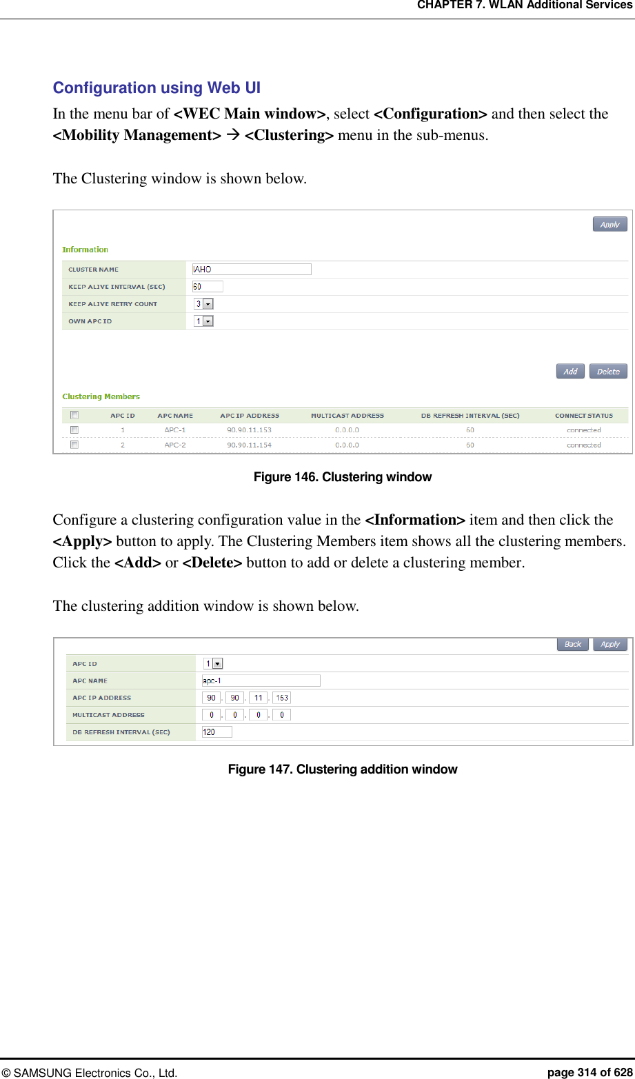
![CHAPTER 7. WLAN Additional Services © SAMSUNG Electronics Co., Ltd. page 315 of 628 7.10 Limiting the Number of Connected Users The W-EP wireless LAN system limits the number of wireless terminals connected to each AP. The limitation is per radio (2.4/5 GHz bandwidth) or WLAN for each AP. 7.10.1 Limiting Connections per Radio Configuration using CLI 1) Go to configure mode of CLI. APC# configure terminal APC/configure# 2) Configure connection limitation. [RADIO] max-associated-stations [MAX_STATION] global: Configures connection limitation per wireless bandwidth. When you enter the ‘global’ parameter at the end, connection limitation is applied to all the APs. [RADIO] max-associated-stations [MAX_STATION] [TARGET] [AP_ID]: Configures connection limitation to a specific AP. Parameter Description RADIO Wireless area to configure [80211bg/80211a] - 80211bg: 2.4 GHz area - 80211a: 5 GHz area MAX-STATION Maximum number of wireless terminals that can be connected (default: 127) TARGET Configuration range - AP: Index of an AP to configure - Global: All APs connected to an APC AP_ID AP ID (range: 1-500) 3) To check the configuration information, use the ‘show 80211bg radio-config global’ command.](https://usermanual.wiki/Samsung-Electronics-Co/WEA463E.Part-1/User-Guide-2696662-Page-315.png)
![CHAPTER 7. WLAN Additional Services © SAMSUNG Electronics Co., Ltd. page 316 of 628 Configuration using Web UI In the menu bar of <WEC Main window>, select <Configuration> and then select the <Radio> <802.11a/n> or <802.11b/g/n> <General> menu in the sub-menus. Figure 148. Configuring connection limitation per radio After configuring MAX CLIENT COUNTS, click the <Apply> button. 7.10.2 Connection Limitation per WLAN Configuration using CLI To configure connection limitation per WLAN, execute the command as follows: 1) Go to configure wlan configuration mode of CLI. APC# configure terminal APC/configure# wlan 1 APC/configure/wlan 1# 2) Disable the WLAN. APC/configure/wlan 1# no enable 3) Configure connection limitation. max-associated-stations [MAX-STATION] Parameter Description MAX-STATION Maximum number of wireless terminals that can be connected (default: 127)](https://usermanual.wiki/Samsung-Electronics-Co/WEA463E.Part-1/User-Guide-2696662-Page-316.png)
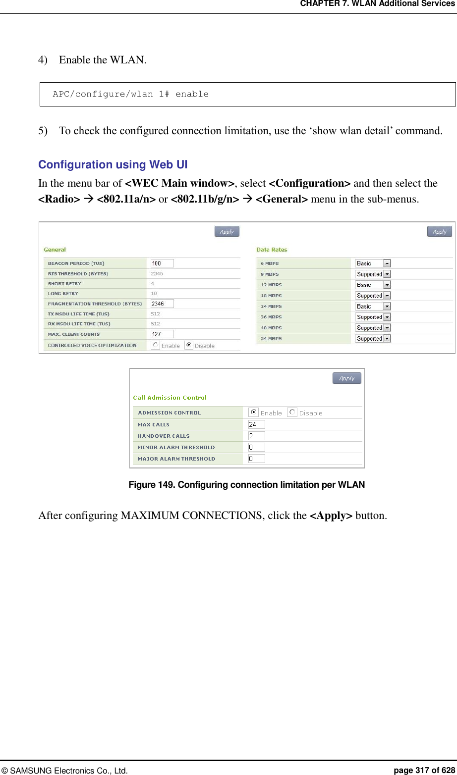
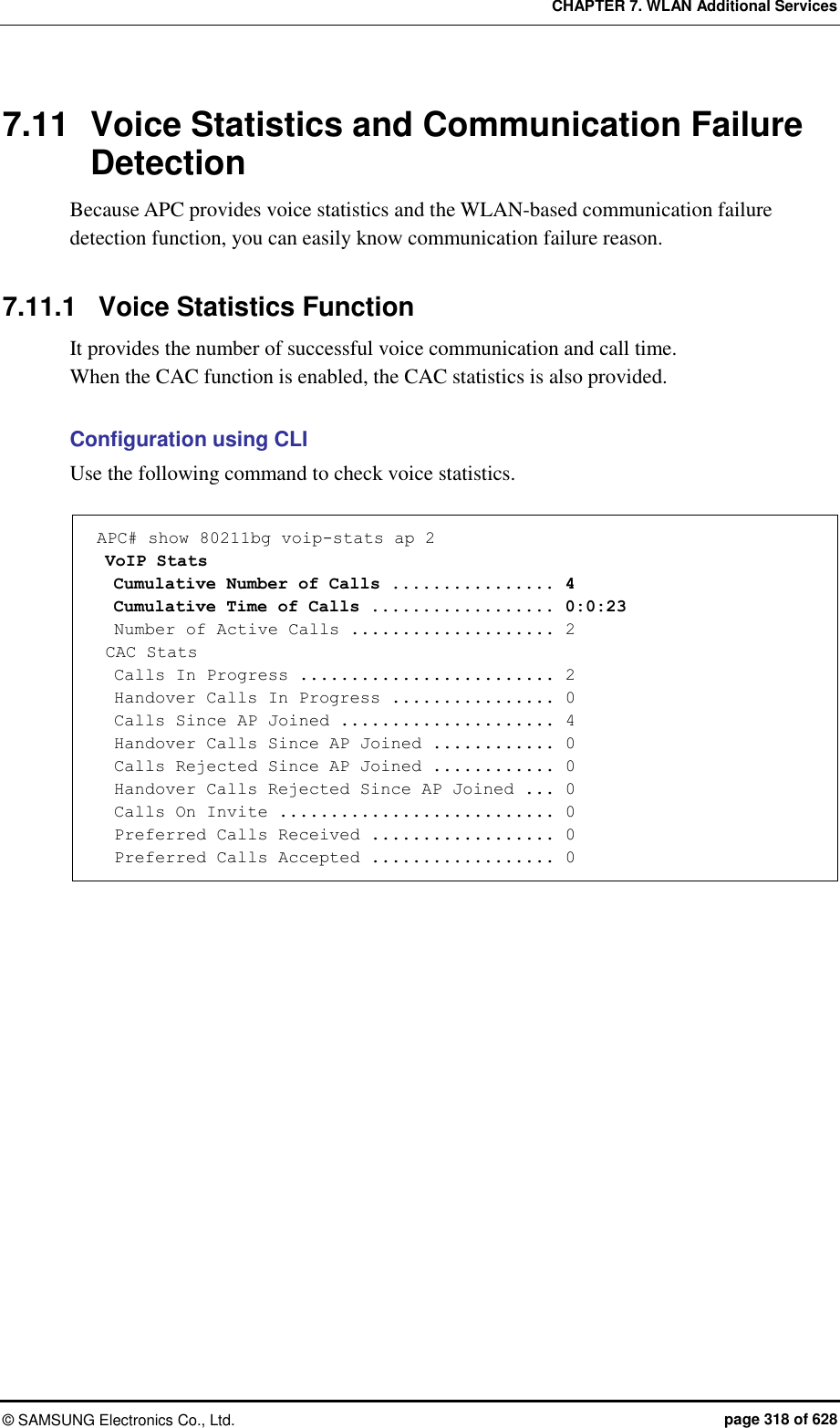
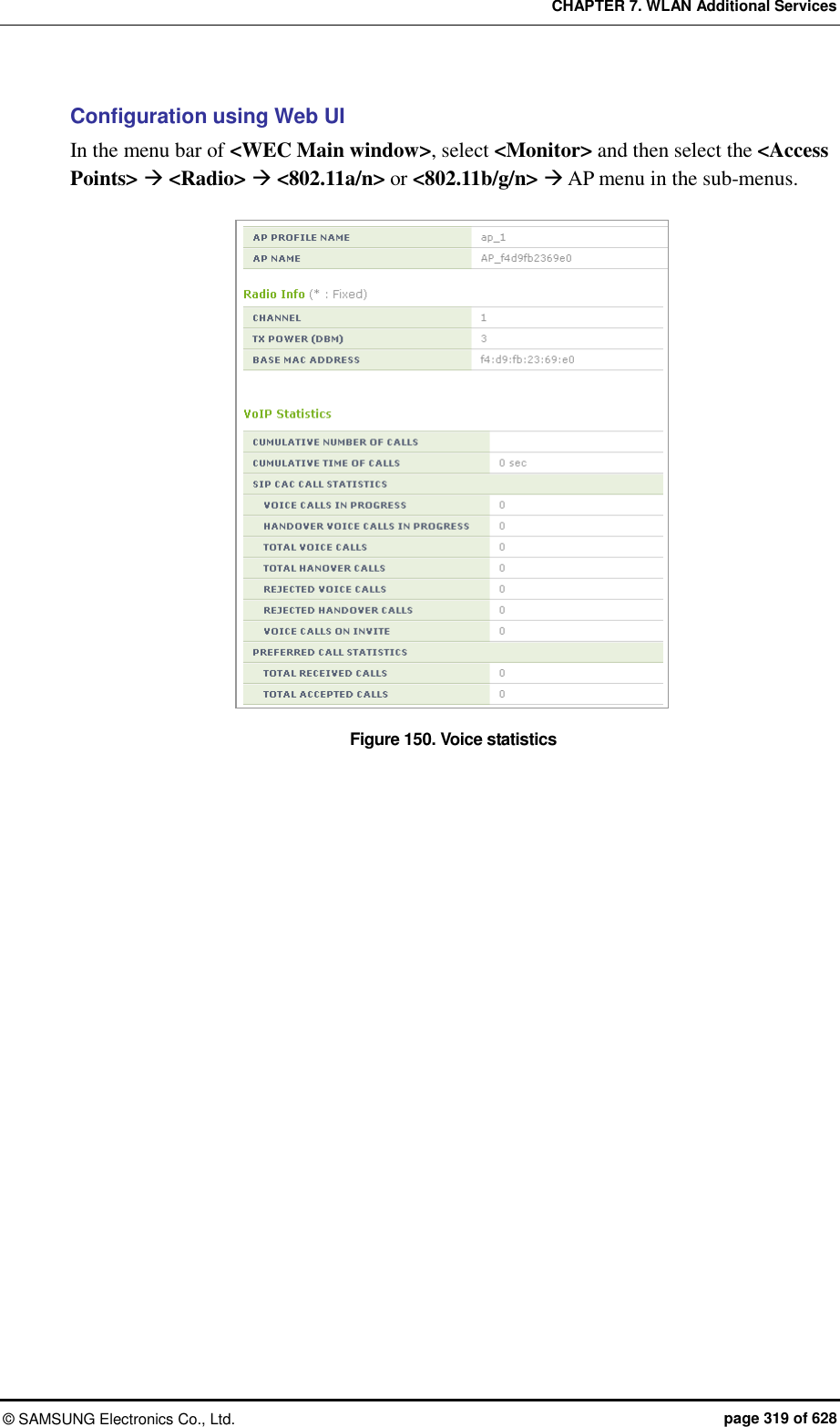
![CHAPTER 7. WLAN Additional Services © SAMSUNG Electronics Co., Ltd. page 320 of 628 7.11.2 Detecting WLAN-based Communication Failure You can configure whether to detect WLAN-based communication failure. Configuration using CLI 1) Go to configure mode of CLI. APC# configure terminal APC/configure# 2) Enable or disable communication failure detection. [no] call-fail-detect [WLAN_ID] Parameter Description WLAN_ID WLAN ID (range: 1-240) 3) To check the configured connection limitation information, use the ‘show voip config [WLAN_ID]’ command. Configuration using Web UI In the menu bar of <WEC Main window>, select <Configuration> and then select the <WLANs> menu in the sub-menus. Select a WLAN ID to change in the WLANs screen and go to the <Advanced> tab. Figure 151. Detecting WLAN-based communication failure After configuring the VOIP FAILURE DETECT item, click the <Apply> button.](https://usermanual.wiki/Samsung-Electronics-Co/WEA463E.Part-1/User-Guide-2696662-Page-320.png)
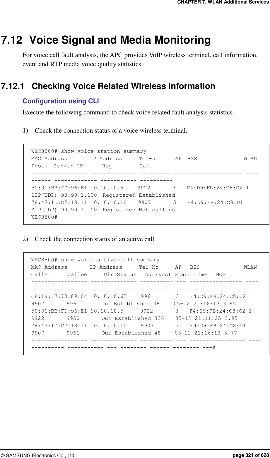
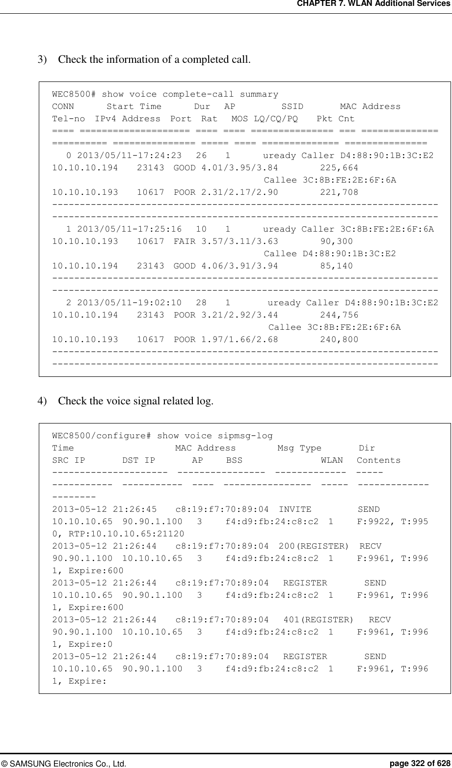
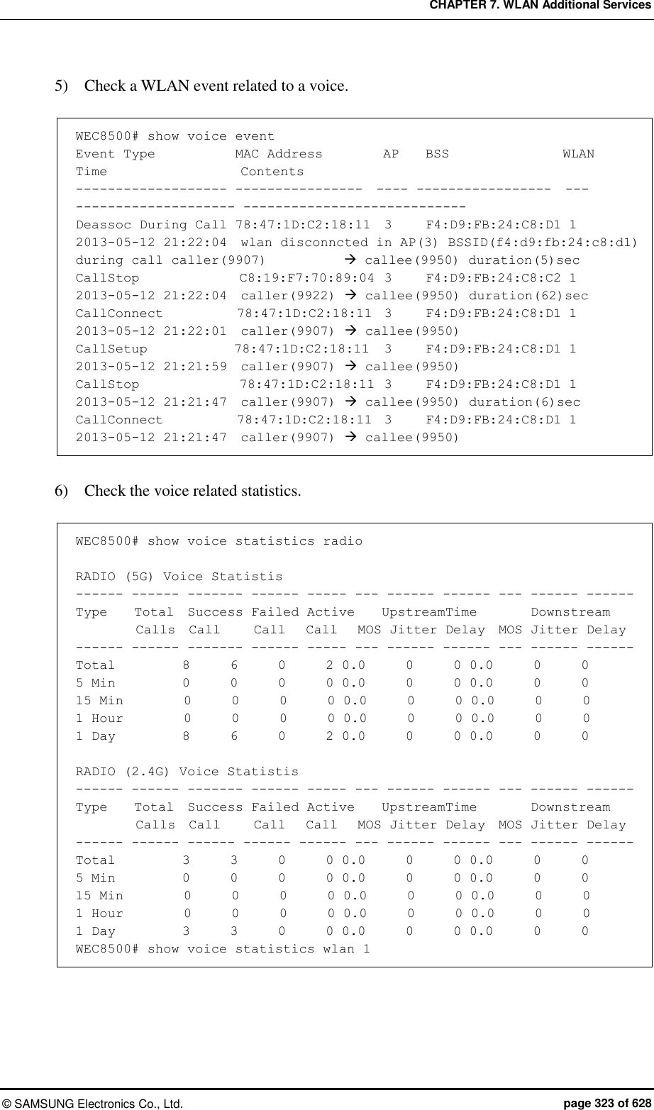
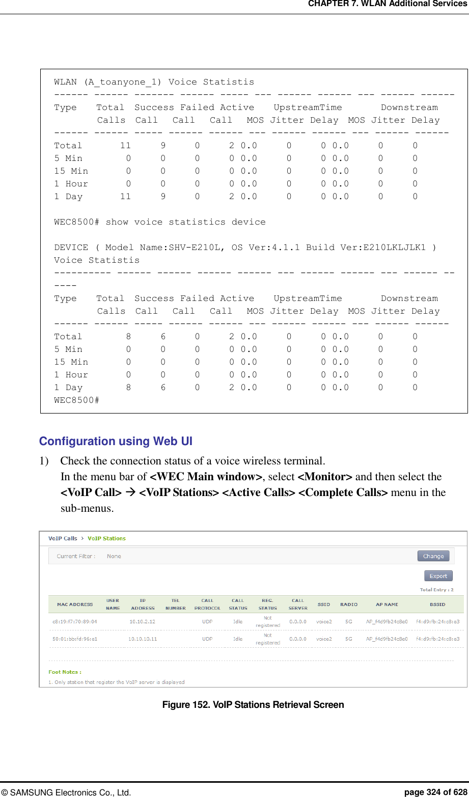
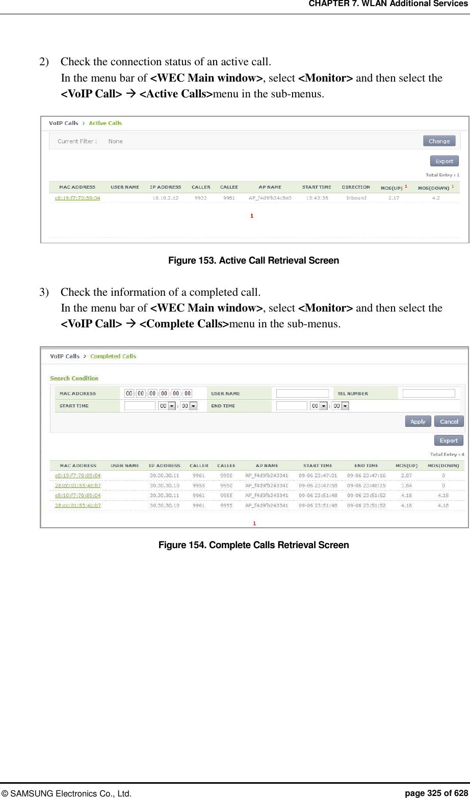
![CHAPTER 7. WLAN Additional Services © SAMSUNG Electronics Co., Ltd. page 326 of 628 7.12.2 Checking Voice Related Quality Information Configuration using CLI Execute the following command to check the voice related quality analysis (Voice Quality Monitoring) information. 1) Operator can check the voice quality analysis information of a wireless terminal that has an active call. WEC8500# show voice vqm current-stats brief ======================================================== [CONN-740 Start Time=2013/7/19.14:47:27, Duration=47 sec(s) Call-ID[f03c77b50564418855587192e12b889d <-> ca371fce-6e10-401a-9a4e-dd53678804c6@ug1.scm.com] Session id :0 SRC [I/F=ge4 Phone-No=9960, IP=20.20.20.30:22458] DST [I/F=ge4 Phone-No=9910, IP=20.20.20.25:25407] RTP Flow Quality Metrics: [Flow-1] DIR=Forward Quality Ratings=Poor [MOS-LQ=3.06, MOS-CQ=2.82, MOS-PQ=3.35] RTP Flow Quality Metrics: [Flow-2] DIR=Reverse Quality Ratings=Good [MOS-LQ=4.04, MOS-CQ=3.95, MOS-PQ=3.89] WEC8500# 2) Operator can check the voice quality analysis information of a wireless terminal that has a completed call. WEC8500# show voice vqm history-stats brief ======================================================== [CONN-1 Start Time=2013/7/19.14:47:27, Duration=75 sec(s) Station Mac [78:47:1d:c5:4c:85:fc:a1:3e:47:59:e7:] startBssid [f4:d9:fb:23:66:10f4:d9:fb:23:66:10] endBssid [f4:d9:fb:23:66:10f4:d9:fb:23:66:10] ssid [Ajay_2_2_4GAjay_2_2_4G] Direction [12] wlanId [22] startApId [22] endApId [22] Session id :0 SRC [I/F=ge4 Call-ID=f03c77b50564418855587192e12b889d Phone-No=9960, IP=20.20.20.30:22458] DST [I/F=ge4 Call-ID=ca371fce-6e10-401a-9a4e-dd53678804c6@ug1.scm.com Phone-No=9910, IP=20.20.20.25:25407] RTP Flow Quality Metrics: [Flow-1] DIR==Forward Quality Ratings=Poor [MOS-LQ=2.21, MOS-CQ=1.33, MOS-PQ=2.84] RTP Flow Quality Metrics: [Flow-2] DIR==Reverse Quality Ratings=Poor [MOS-LQ=2.46, MOS-CQ=1.50, MOS-PQ=3.00] ======================================================== [CONN-2 Start Time=2013/7/19.14:52:36, Duration=30 sec(s) Station Mac [fc:a1:3e:47:59:e7:78:47:1d:c5:4c:85:] startBssid [f4:d9:fb:23:66:10f4:d9:fb:23:66:10] endBssid [f4:d9:fb:23:66:10f4:d9:fb:23:66:10]](https://usermanual.wiki/Samsung-Electronics-Co/WEA463E.Part-1/User-Guide-2696662-Page-326.png)
![CHAPTER 7. WLAN Additional Services © SAMSUNG Electronics Co., Ltd. page 327 of 628 ssid [Ajay_2_2_4GAjay_2_2_4G] Direction [12] wlanId [22] startApId [22] endApId [22] Session id :1 SRC [I/F=ge4 Call-ID=035be38a40032eb8edb0b94e944d58d4 Phone-No=9910, IP=20.20.20.25:25407] DST [I/F=ge4 Call-ID=917a913e-83ae-497f-ad84-bf0ee80edf36@ug1.scm.com Phone-No=9960, IP=20.20.20.30:22458] RTP Flow Quality Metrics: [Flow-1] DIR==Forward Quality Ratings=Fair [MOS-LQ=3.73, MOS-CQ=3.65, MOS-PQ=3.72] RTP Flow Quality Metrics: [Flow-2] DIR==Reverse Quality Ratings=Poor [MOS-LQ=3.30, MOS-CQ=3.06, MOS-PQ=3.49] ======================================================== [CONN-3 Start Time=2013/7/19.14:53:12, Duration=24 sec(s) Station Mac [78:47:1d:c5:4c:85:fc:a1:3e:47:59:e7:] startBssid [f4:d9:fb:23:66:10f4:d9:fb:23:66:10] endBssid [f4:d9:fb:23:66:10f4:d9:fb:23:66:10] ssid [Ajay_2_2_4GAjay_2_2_4G] Direction [12] wlanId [22] startApId [22] endApId [22] Session id :2 SRC [I/F=ge4 Call-ID=a47241e5f5d3d6b7f942d0aaeddbd8ef Phone-No=9960, IP=20.20.20.30:22458] DST [I/F=ge4 Call-ID=65031276-a4dd-4b1c-a718-4ed3188e44a5@ug1.scm.com Phone-No=9910, IP=20.20.20.25:25407] RTP Flow Quality Metrics: [Flow-1] DIR==Forward Quality Ratings=Poor [MOS-LQ=3.25, MOS-CQ=2.96, MOS-PQ=3.47] RTP Flow Quality Metrics: [Flow-2] DIR==Reverse Quality Ratings=Fair [MOS-LQ=3.65, MOS-CQ=3.57, MOS-PQ=3.68] WEC8500# 3) Operator can check the call statistics information. WEC8500# show voice vqm summary-stats ======================================================== VQM Summary Stats for last YEAR:0 MONTH:0 DAY:0 0 HR:26 MN:44 SEC Calls Active = 0 Calls Terminated = 3 Flows Quality Summary (Total/Good/Fair/Poor) = 6/0/2/4 Listening Call Quality (MOS) min/ave/max = 2.21/3.10/3.73 Conversational Call Quality (MOS) min/ave/max = 1.33/2.68/3.65 P.862 Raw Quality (MOS) min/ave/max = 2.84/3.36/3.72 Listening Call Quality (R-factor) min/ave/max = 45/63/77 Conversational Call Quality (R-factor) min/ave/max = 24/53/75 Packet Delay Variation (msec) ave/max = 13/25 Packet Received/Processed/Lost/Discarded = 12980/12909/93/1154 Packet Duplicate/OutOfseq = 0/135 Packet Error Stats: Ignored/Errors = 71/1 System Error Stats: Resource Unavail/Filter Mismatch/Limit Exceeded = 0/0/0 Voice Quality Alerts: Low R-factor/Excess Loss/Excess Delay/Upload = 1/6/5/0](https://usermanual.wiki/Samsung-Electronics-Co/WEA463E.Part-1/User-Guide-2696662-Page-327.png)
![CHAPTER 7. WLAN Additional Services © SAMSUNG Electronics Co., Ltd. page 328 of 628 Upload Count = 1141 Upload Ok Count = 0 Upload Fail Count = 0 Requested Count = 1141 WEC8500# 4) Operator can check the alarm information that occurs during call. WEC8500# show voice vqm alarms brief ======================================================== VQM ActiveRfactor/ActivePktLoss/ActivePktDly/ActiveMos = 1/1/1/1 VQM QualityThresh/LossThresh/DelayThresh/MOSThresh = 50/50/195/35 ALARMS REPORTED : Src Call Id = f03c77b50564418855587192e12b889d Dst Call Id = ca371fce-6e10-401a-9a4e-dd53678804c6@ug1.scm.com Session = 0 Direction :Forward Type : [Low-Quality] [Excessive Burst] [Excessive delay] Direction :Reverse Type : [Excessive Burst] [Excessive delay] ALARMS REPORTED : Src Call Id = 035be38a40032eb8edb0b94e944d58d4 Dst Call Id = 917a913e-83ae-497f-ad84-bf0ee80edf36@ug1.scm.com Session = 1 Direction :Forward Type : [Excessive Burst] Direction :Reverse Type : [Excessive Burst] [Excessive delay] ALARMS REPORTED : Src Call Id = a47241e5f5d3d6b7f942d0aaeddbd8ef Dst Call Id = 65031276-a4dd-4b1c-a718-4ed3188e44a5@ug1.scm.com Session = 2 Direction :Forward Type : [Excessive Burst] Direction :Reverse Type : [Excessive Burst] WEC8500#](https://usermanual.wiki/Samsung-Electronics-Co/WEA463E.Part-1/User-Guide-2696662-Page-328.png)
![CHAPTER 7. WLAN Additional Services © SAMSUNG Electronics Co., Ltd. page 329 of 628 7.13 Multicast Stream Admission Control The multicast stream admission control is provided to protect the currently running multicast streams from new streams that flow into the wireless LAN. When the maximum allowed usage of streams or channels per radio is reached, the APC does not allow any additional streams. 7.13.1 Configuring Admission Control The multicast stream admission control function configures the maximum number of streams or the maximum usage of channels to protect the currently running multicast streams. It denies multicast streaming requests once the maximum number of streams or the maximum usage of channels is reached. You can set the number of marginal streams or the usage of channels with consideration for handover. Configuration using CLI To set multicast stream admission control, execute the following commands: 1) Configuration mode of CLI enter the multicast stream admission control mode of the desired wireless section. APC# configure terminal APC/configure# [80211a/80211bg] msac APC/configure/80211a/msac# 2) Enable or disable the multicast stream admission control function. acm [MODE] Parameter Description Mode Whether or not to use the multicast stream admission control (enable/disable) - enable: Enable - disable: Disable 3) Configure the maximum allowed number of streams. max-streams [VALUE] Parameter Description VALUE Maximum allowed number of streams](https://usermanual.wiki/Samsung-Electronics-Co/WEA463E.Part-1/User-Guide-2696662-Page-329.png)
![CHAPTER 7. WLAN Additional Services © SAMSUNG Electronics Co., Ltd. page 330 of 628 4) Set the maximum allowed usage of channels. max-chan-util [VALUE] Parameter Description VALUE Maximum allowed usage of channels 5) Configure the number of marginal streams with consideration for handover. reserved-ho-streams [VALUE] Parameter Description VALUE Number of marginal streams with consideration for handover 6) Configure the usage of marginal channels with consideration for handover. reserved-ho-chan-util [VALUE] Parameter Description VALUE Usage of marginal channels with consideration for handover 7) You can view the information you configured by using the ‘show[80211a | 80211bg] msac configuration’ command. Configuration using Web UI From the menu bar of <WEC Main Window>, select <Configuration> and then select <Radio> <802.11a/n> or <802.11b/g/n> <Admission Control> in the submenus. Figure 155. 802.11a/n Admission Control Configuration Window](https://usermanual.wiki/Samsung-Electronics-Co/WEA463E.Part-1/User-Guide-2696662-Page-330.png)
![CHAPTER 7. WLAN Additional Services © SAMSUNG Electronics Co., Ltd. page 331 of 628 After configuring the items below in the Multicast Stream Admission Control, click the <Apply> button. ADMISSION CONTROL: Configure the CAC function METHOD: Select the method of admission control MAX STREAMS: Maximum allowed number of streams (range: 1-20) HANDOVER STREAMS: Number of marginal streams with consideration for handover (range: 0-6) The maximum allowed number of streams becomes MAX STREAMS-HANDOVER STREAMS. MAX CHANNEL UTILIZATION (%): Maximum allowed usage of channels (range: 5-85) HANDOVER CHANNEL UTILIZATION (%): Usage of marginal channels with consideration for handover (range: 0-30) 7.14 Wi-Fi Band Steering This is a function of leading a UE which supports the Dual Band (2.4/5.0 GHz) to be connected to 2.4 GHz or 5.0 GHz to secure more stabilized performance if many resources are used in a specific radio. 7.14.1 Activating Band Steering Function You can activate the Band Steering function by WLAN and the 5.0 GHz band steering is set as default upon Band Steering On. Configuration using CLI To activate or deactivate the Band Steering function, execute the command as follows: 1) Configure a specific WLAN which requires the steering band. APC# configure terminal APC/configure# wlan 1 APC/configure/wlan 1# 2) Activate or deactivate the Band Steering function. band-steering [MODE] Parameter Description Mode Whether to configure the Band Steering function - enable: Setting - disable: Release (by default)](https://usermanual.wiki/Samsung-Electronics-Co/WEA463E.Part-1/User-Guide-2696662-Page-331.png)
![CHAPTER 7. WLAN Additional Services © SAMSUNG Electronics Co., Ltd. page 332 of 628 WEC8500/configure/wlan 1# band-steering enable WLAN (1) band steering is On (5-GHz preferred) WEC8500/configure/wlan 1# no band-steering enable WLAN (1) band steering is Off 3) Select a steering band. band-steering [VALUE] Parameter Description VALUE 1 (5.0 GHz), 2 (2.4 GHz) WEC8500/configure/wlan 1# band-steering 1 WLAN (1) band steering is On (5-GHz preferred) WEC8500/configure/wlan 1# band-steering 2 WLAN (1) band steering is On (2.4-GHz preferred) 4) Add an entry to the dual band station database. band-steering add-station [MAC] Parameter Description MAC Station MAC Address WEC8500/configure/wlan 1# band-steering add-station 00:00:00:00:00:01 WLAN(1): add station(00:00:00:00:00:01), prefer a band(5-GHz) are set 5) Delete an entry from the dual band station database. band-steering delete-station [MAC] Parameter Description MAC Station MAC Address WEC8500/configure/wlan 1# band-steering delete-station 00:00:00:00:00:01 Deleted... 6) Delete all entries from the dual band station database. band-steering delete-all WEC8500/configure/wlan 1# band-steering delete-all WLAN(1): all stations are deleted...](https://usermanual.wiki/Samsung-Electronics-Co/WEA463E.Part-1/User-Guide-2696662-Page-332.png)
![CHAPTER 7. WLAN Additional Services © SAMSUNG Electronics Co., Ltd. page 333 of 628 Configuration using Web UI WLAN > Advanced > BAND STEERING [Disable][2.4 GHz preferred][5 GHz preferred] Figure 156. Band Steering Function On/Off and Band Setting](https://usermanual.wiki/Samsung-Electronics-Co/WEA463E.Part-1/User-Guide-2696662-Page-333.png)
![CHAPTER 7. WLAN Additional Services © SAMSUNG Electronics Co., Ltd. page 334 of 628 7.15 Wi-Fi Load Balancing The load balancing function in the AP Controller is a function of load balancing by transferring the message that the connections to wireless stations among APs have been permitted or cannot be permitted based on the set threshold value and then controlling the number of stations connected to APs. 7.15.1 Activating Load Balancing Function The setting can be made based on the WLAN and it is possible to check the load balancing function among APs for stations attempting at association to APs with the threshold value and the maximum denial count value based on station count. Configuration using CLI For the load balancing function, execute the command as follows: 1) Configure a specific WLAN which requires load balancing. APC# configure terminal APC/configure# wlan 1 APC/configure/wlan 1# 2) Activate or deactivate the Load Balancing function. load-balancing [MODE] Parameter Description Mode Whether to configure the Load Balancing function - enable: Setting - disable: Release (by default) WEC8500/configure/wlan 1# load-balancing enable WLAN (1), Wi-Fi Load Balancing: Enable WEC8500/configure/wlan 1# no load-balancing enable WLAN (1), Wi-Fi Load Balancing: Disable 3) Configure the load balancing station count threshold value. load-balancing threshold_station [VALUE] Parameter Description VALUE 1-127 (127 by default)](https://usermanual.wiki/Samsung-Electronics-Co/WEA463E.Part-1/User-Guide-2696662-Page-334.png)
![CHAPTER 7. WLAN Additional Services © SAMSUNG Electronics Co., Ltd. page 335 of 628 WEC8500/configure/wlan 1# load-balancing threshold_station 100 Wi-Fi Load Balancing threshold: 100 stations 4) Configure the maximum denial count value. load-balancing denial_count [VALUE] Parameter Description VALUE 1-10 (2 by default) WEC8500/configure/wlan 1# load-balancing denial_count 4 Wi-Fi Load Balancing MAX denial count: 4 Configuration using Web UI Configure WLAN > Advanced > LOAD BALANCING[Enable] [Disable] WLAN > Advanced > THRESHOLD[Value] WLAN > Advanced > MAXIMUM DENIAL COUNT[Value]. Figure 157. Configuring Load Balancing Function](https://usermanual.wiki/Samsung-Electronics-Co/WEA463E.Part-1/User-Guide-2696662-Page-335.png)
![CHAPTER 7. WLAN Additional Services © SAMSUNG Electronics Co., Ltd. page 336 of 628 7.16 Station-based Adaptive Load Balancing Station-based Adaptive Load Balancing performs load balancing based on the number of stations and RSSI in an individual radio unit of the AP group. Configuring Basic Function and Setting Load Balancing Parameters of AP Group are available and the settings of the load balancing parameters in individual APs are available to apply a different value set only for a specific AP. 7.16.1 Basic Setting of Station-based Adaptive Load Balancing Station-based Adaptive Load Balancing operates only when it is enabled in the setting of the basic functions and configures options applied to the overall function operation. Configuration using CLI To configure the basic function, execute the commands as follows: 1) Go to the configure load-balancing configuration mode of CLI. APC# configure terminal APC/configure# load-balancing APC/configure/load-balancing# 2) Activate the Station-based Adaptive Load Balancing function. enable 3) If a function of distributing stations uniformly among APs is necessary, activate the Active Load Balancing function (Default: no active). active 4) To activate the Active Load Balancing function, set up the interval for attempting to distribute uniformly. interval [NUMBER] Parameter Description NUMBER Interval for performing active load balancing (sec) 5) To allow load balancing among APs which use the same channel, set the following option (Default: no allow-channel): allow-channel](https://usermanual.wiki/Samsung-Electronics-Co/WEA463E.Part-1/User-Guide-2696662-Page-336.png)
![CHAPTER 7. WLAN Additional Services © SAMSUNG Electronics Co., Ltd. page 337 of 628 6) To calibrate the RSSI value depending on types of stations, the calibration value must be set. calibration mobile [NUMBER] calibration pc [NUMBER] calibration others [NUMBER] Parameter Description NUMBER RSSI calibration value (-dbm) - Default value: 0 dbm 7) To exclude stations where the traffic occurs from load balancing, the following option must be set (Default: no idle-station): idle-station 7.16.2 Setting AP Group Parameter Station-based Adaptive Load Balancing must set operating parameters to the radio of the corresponding AP group because it operates in a radio unit of the AP group. Configuration using CLI To set AP group parameters, execute the command as follows: 1) Go to the load-balancing configuration mode in configure AP Group of CLI. APC# configure terminal APC/configure# ap-group lb APC/configure/ap-group lb# load-balancing APC/configure/ap-group lb/load-balancing# 2) Go to the radio to perform the Station-based Adaptive Load Balancing function. APC/configure/ap-group lb/load-balancing# radio 1 APC/configure/ap-group lb/load-balancing/radio 1# 3) Activate load balancing in the corresponding radio. enable 4) Set the interval to attempt at the Load Balancing function. interval [NUMBER] Parameter Description NUMBER Interval for performing load balancing (sec)](https://usermanual.wiki/Samsung-Electronics-Co/WEA463E.Part-1/User-Guide-2696662-Page-337.png)
![CHAPTER 7. WLAN Additional Services © SAMSUNG Electronics Co., Ltd. page 338 of 628 5) Set the station threshold to perform the Load Balancing function. threshold [NUMBER] Parameter Description NUMBER Station threshold as the standard for the performance of load balancing 6) Set the time of blocking the reconnection after the load of the station is now balanced. kickout-timeout [NUMBER] Parameter Description NUMBER Reconnection limit time (0~100 sec.) 7) To lead the station which performs load balancing to connect to a specific AP, set the probe response limit time to other APs. no-probe-timeout [NUMBER] Parameter Description NUMBER Probe response limit time (0~100 sec.) 8) The rssi-high value is a criterion for excluding candidates for load balancing to be selected. The station with the RSSI value higher than the set value does not attempt at load balancing (In case of the active mode, N/A). rssi-high [NUMBER] Parameter Description NUMBER RSSI reference value (-100~0 dbm) 9) The rssi-low value is a criterion for selecting a sticky station. The station with the RSSI value lower than the set value always attempts at load balancing. rssi-low [NUMBER] Parameter Description NUMBER RSSI reference value (-100~0 dbm)](https://usermanual.wiki/Samsung-Electronics-Co/WEA463E.Part-1/User-Guide-2696662-Page-338.png)
![CHAPTER 7. WLAN Additional Services © SAMSUNG Electronics Co., Ltd. page 339 of 628 7.16.3 Setting AP Parameters Station-based Adaptive Load Balancing operates as the default value of the setting of the AP group but it is possible to set other parameter value to an individual AP. Because it operates in a radio unit, the parameters to change must be set to the individual radio of the corresponding AP must be set. Configuration using CLI To set AP parameters, execute the command as follows: 1) Go to the load-balancing configuration mode in configure AP of CLI. APC# configure terminal APC/configure# ap ap_1 APC/configure/ap ap_1# load-balancing APC/configure/ap ap_1/load-balancing# 2) Go to the radio to perform the Station-based Adaptive Load Balancing function. APC/configure/ap ap_1/load-balancing# radio 1 APC/configure/ap ap_1/load-balancing/radio 1# 3) Activate load balancing in the corresponding radio. enable 4) Set the station threshold to perform the Load Balancing function. interval [NUMBER] Parameter Description NUMBER Interval for performing load balancing (sec) 5) Set the station threshold to perform the Load Balancing function. threshold [NUMBER] Parameter Description NUMBER Station threshold as the standard for the performance of load balancing](https://usermanual.wiki/Samsung-Electronics-Co/WEA463E.Part-1/User-Guide-2696662-Page-339.png)
![CHAPTER 7. WLAN Additional Services © SAMSUNG Electronics Co., Ltd. page 340 of 628 6) Set the time of blocking the reconnection after the load of the station is now balanced. kickout-timeout [NUMBER] Parameter Description NUMBER Reconnection limit time (0~100 sec.) 7) To lead the station which performs load balancing to connect to a specific AP, set the probe response limit time to other APs. no-probe-timeout [NUMBER] Parameter Description NUMBER Probe response limit time (0~100 sec.) 8) The rssi-high value is a criterion for excluding candidates for load balancing to be selected. The station with the RSSI value higher than the set value does not attempt at load balancing (In case of the active mode, N/A). rssi-high [NUMBER] Parameter Description NUMBER Probe response limit time (0~100 sec.) 9) The rssi-high value is a criterion for excluding candidates for load balancing to be selected. The station with the RSSI value higher than the set value does not attempt at load balancing (In case of the active mode, N/A). rssi-low [NUMBER] Parameter Description NUMBER RSSI reference value (-100~0 dbm)](https://usermanual.wiki/Samsung-Electronics-Co/WEA463E.Part-1/User-Guide-2696662-Page-340.png)
![CHAPTER 8. Security © SAMSUNG Electronics Co., Ltd. page 341 of 628 CHAPTER 8. Security The W-EP wireless LAN system supports the security function, required in a wire/wireless network environment, such as RADIUS server interoperation function, system user management, guest connection service, unauthorized AP/terminal detection and simple blocking function, firewall, access control (ACL), etc. In this chapter, how to configure various security functions supported in the system is described. 8.1 RADIUS Server Configuration The W-EP wireless LAN system provides the security and authentication function by interoperating with an external RADIUS server. The WEC8050 also provides the internal RADIUS server function. 8.1.1 External RADIUS Server The W-EP wireless LAN system provides the security and authentication function by interoperating with an external RADIUS server. Follow the below procedure to interoperate with a RADIUS server. 8.1.1.1 Basic Settings The basic steps for configuring a RADIUS server are as follows: Configuration using CLI 1) Go to configure security radius configuration mode of CLI. WEC8500# configure terminal WEC8500/configure# security WEC8500/configure/wlan 1/security# radius 1 WEC8500/configure/security/radius 1# 2) Configure the IP address of a RADIUS server. WEC8500/configure/security/radius 1# serverIp [IP_ADDRESS]](https://usermanual.wiki/Samsung-Electronics-Co/WEA463E.Part-1/User-Guide-2696662-Page-341.png)
![CHAPTER 8. Security © SAMSUNG Electronics Co., Ltd. page 342 of 628 Parameter Description IP_ADDRESS The IP address of a RADIUS server 3) Configure the key of a RADIUS server. WEC8500/configure/security/radius 1# secret [KEY_TYPE] [KEY_STRING] Parameter Description KEY_TYPE RADIUS server key input format - ASCII: ASCII character string - HEX: Hexadecimal value KEY_STRING RADIUS server key 4) Enable the accounting function of a RADIUS server and configure the port number. WEC8500/configure/security/radius 1# acct [PORT_NUMBER] Parameter Description PORT_NUMBER Accounting port number of a RADIUS server (range: 1-65535, default: 1813) 5) Configure the authentication port number of a RADIUS server. WEC8500/configure/security/radius 1# auth [PORT_NUMBER] Parameter Description PORT_NUMBER Accounting port number of a RADIUS server (range: 1-65535, default: 1812) 6) Configure the items related to retransmissions in RADIUS communications. You can use default values without changing configuration. WEC8500/configure/security/radius 1# retransmit-interval [RETRY_INTERVAL] WEC8500/configure/security/radius 1# retransmit-count [RETRY_COUNT] WEC8500/configure/security/radius 1# fo-retransmit-count [FO_RETRY_COUNT]](https://usermanual.wiki/Samsung-Electronics-Co/WEA463E.Part-1/User-Guide-2696662-Page-342.png)
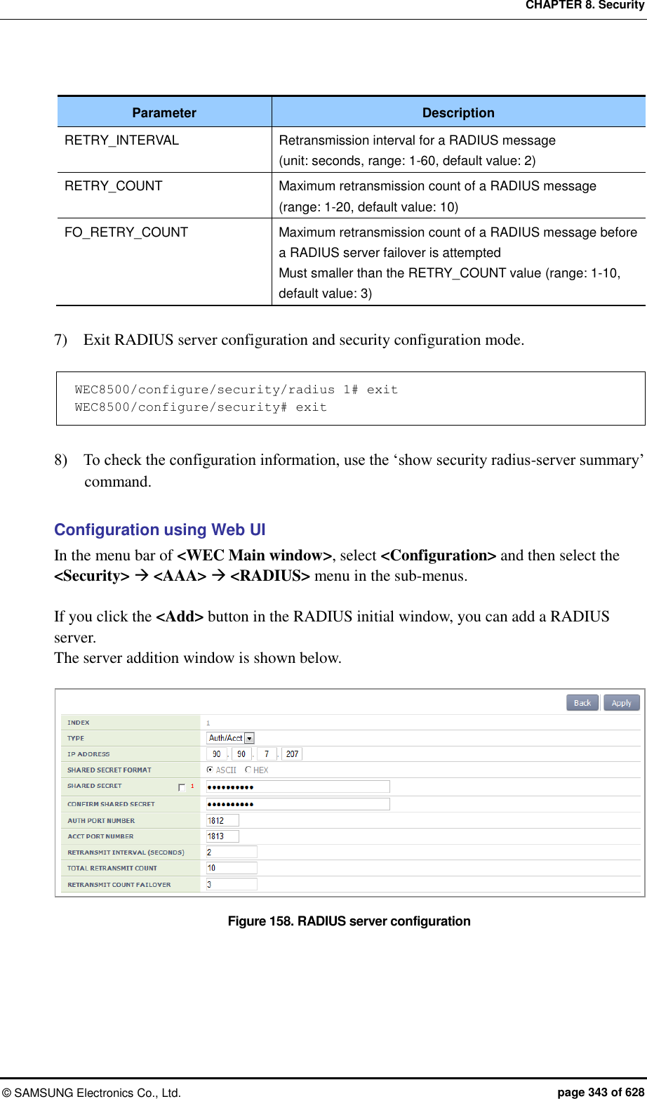
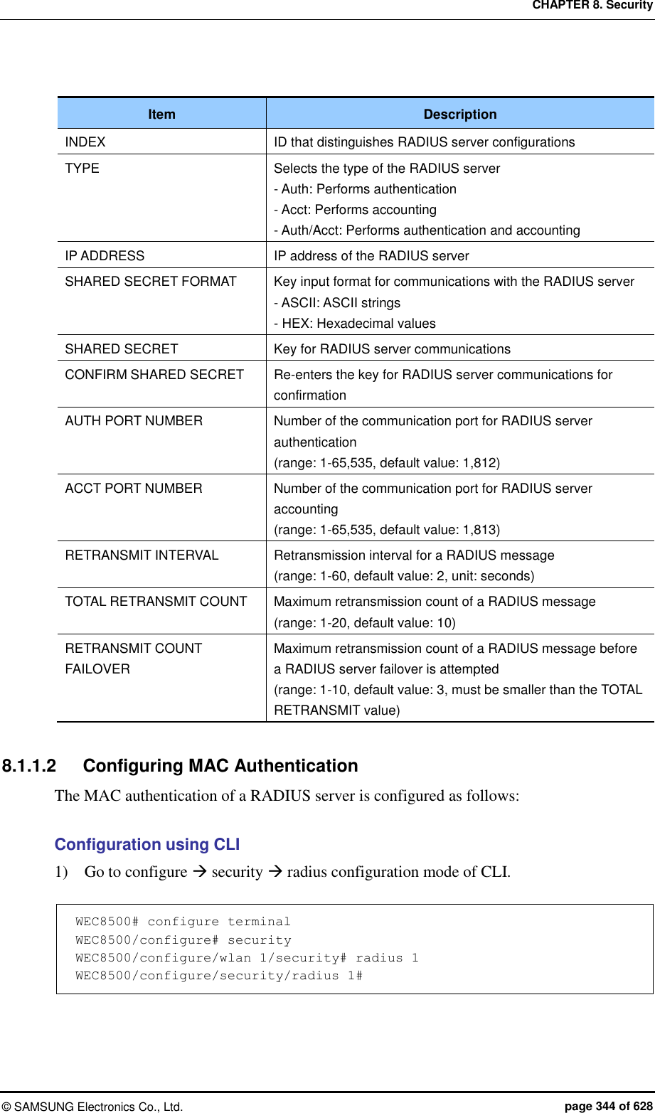
![CHAPTER 8. Security © SAMSUNG Electronics Co., Ltd. page 345 of 628 2) Set the password type that will be used for the MAC authentication of the device. WEC8500/configure/security/radius 1# mac-auth-pw-type [PW_TYPE] Parameter Description PW_TYPE Password type (default value: mac) - mac: MAC address of the device. Note: it must be a string whose type must be the same as that of the MAC string which is used as a user ID when the MAC authentication of the device is performed - shared-secret: Key shared between the APC and RADIUS server 3) Set the type of separator of the device’s MAC string which is used as a user ID when the MAC authentication of the device is performed. WEC8500/configure/security/radius 1# mac-auth-delimiter [DELIMITER_TYPE] Parameter Description DELIMITER_TYPE Type of the MAC string separator (default: none) - none: no separator (xxxxxxxxxxxx) - colon: Uses ‘:’ as a separator (xx:xx:xx:xx:xx:xx) - hyphen: Uses ‘-’ as a separator (xx-xx-xx-xx-xx-xx) - single-hyphen: Uses only one ‘-’ in the middle (xxxxxx-xxxxxx) 4) Configure whether to use lowercase characters or uppercase characters for the device’s MAC string that will be used as an ID upon the MAC authentication of the device. WEC8500/configure/security/radius 1# mac-auth-case [CASE_TYPE] Parameter Description CASE_TYPE Case type of the device’s MAC string (default value: lower) - lower: Uses lowercase - upper: Uses uppercase 5) Exit RADIUS server configuration and then security configuration mode. WEC8500/configure/security/radius 1# exit WEC8500/configure/security# exit 6) You can view configuration information by using the ‘show security radius-server detail <server-id>’ command.](https://usermanual.wiki/Samsung-Electronics-Co/WEA463E.Part-1/User-Guide-2696662-Page-345.png)
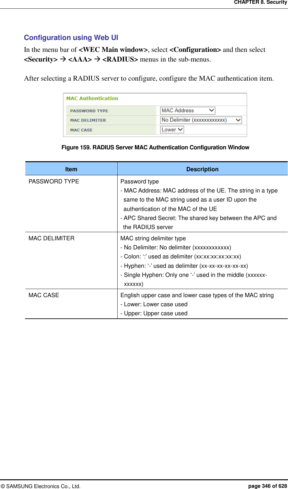
![CHAPTER 8. Security © SAMSUNG Electronics Co., Ltd. page 347 of 628 8.1.2 Internal RADIUS Server The W-EP wireless LAN system provides the security and authentication function by interoperating with an internal RADIUS server. To use the internal RADIUS server, operator can add, delete, or edit a user (WEC8500: maximum 2048 users, WEC8050: maximum 512 users). Configuration using CLI To configure a local network user related function, enter into the ‘radiuscm’ of configure mode by executing the following command. WEC8050# configure terminal WEC8050/configure# radiuscm Operator can execute various commands for Local Net Users. [Adding User] To add a user to the Local Net Users, execute the following command. Add-local-userdb {username} {password} [name] [email] [department] [home_phone] [work_phone] [mobile_phone] Parameter Description Username Login ID of a user - Character varying (1-63) - MANDATORY - Korean is not allowed. - Special characters {, }, (, ), ,, ;, +=, -=,:=, =, !=, >=, >, <=, <, = - , ! - , =*, !*, ==, #, “”, ‘‘, ``, *, ?, \, space, & Cannot be used. Password User’s password - Character varying (1-63) - MANDATORY - Korean is not allowed. - Special characters {, }, (, ), ,, ;, +=, -=,:=, =, !=, >=, >, <=, <, = - , ! - , =*, !*, ==, #, “”, ‘‘, ``, *, ?, \, space, & Cannot be used. Name Name - Character varying (1-63) - OPTIONAL - Korean is not allowed. - Special characters ‘, *, ?, \, ; cannot be used. email email address - Character varying (1-63) - OPTIONAL](https://usermanual.wiki/Samsung-Electronics-Co/WEA463E.Part-1/User-Guide-2696662-Page-347.png)
![CHAPTER 8. Security © SAMSUNG Electronics Co., Ltd. page 348 of 628 Parameter Description - Korean is not allowed. - Special characters ‘, *, ?, \, ; cannot be used. department Division information - Character varying (1-63) - OPTIONAL - Korean is not allowed. - Special characters ‘, *, ?, \, ; cannot be used. Home_phone Home phone number - Character varying (1-63) - OPTIONAL - Korean is not allowed. - Special characters ‘, *, ?, \, ; cannot be used. Work_phone Office phone number - Character varying (1-63) - OPTIONAL - Korean is not allowed. - Special characters ‘, *, ?, \, ; cannot be used. Mobile_phone Mobile phone number. - Character varying (1-63) - OPTIONAL - Korean is not allowed. - Special characters ‘, *, ?, \, ; cannot be used. [Modifying User] To modify a user from the Local Net Users, execute the following command. modify-local-userdb {username} {password} [name] [email] [department] [home_phone] [work_phone] [mobile_phone] [Deleting User] To delete one user from the Local Net Users, execute the following command. delete-local-userdb {username} Parameter Description Username User’s ID - Character varying (1-63) - MANDATORY - Korean is not allowed. - Special characters {, }, (, ), ,, ;, +=, -=,:=, =, !=, >=, >, <=, <, = - , ! - , =*, !*, ==, #, “”, ‘‘, ``, *, ?, \, space, & Cannot be used. To delete all the users from the Local Net Users, execute the following command. Remove-all-local-userdb](https://usermanual.wiki/Samsung-Electronics-Co/WEA463E.Part-1/User-Guide-2696662-Page-348.png)
![CHAPTER 8. Security © SAMSUNG Electronics Co., Ltd. page 349 of 628 [Importing User] To import the Local Net Users list file, execute the following command. Import-local-userdb {filename} Parameter Description Filename File to import - CSV file format - Filename (1-512) [Exporting User] To export the Local Net Users list file, execute the following command. Export-local-userdb {filename} Parameter Description Filename File to export - CSV file format - Filename (1-512) [Checking User] To check one local net user, execute the following command. Show radiuscm username {username} To check all the local net users, execute the following command. Show radiuscm all-user Configuration using Web UI In the menu bar of <WEC Main window>, select <Configuration> and then select the <Security> <AAA> <Local User> menu in the sub-menus.](https://usermanual.wiki/Samsung-Electronics-Co/WEA463E.Part-1/User-Guide-2696662-Page-349.png)
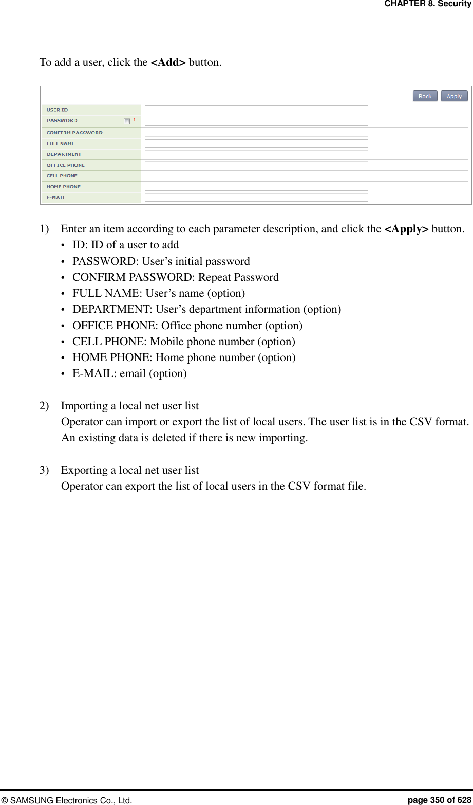
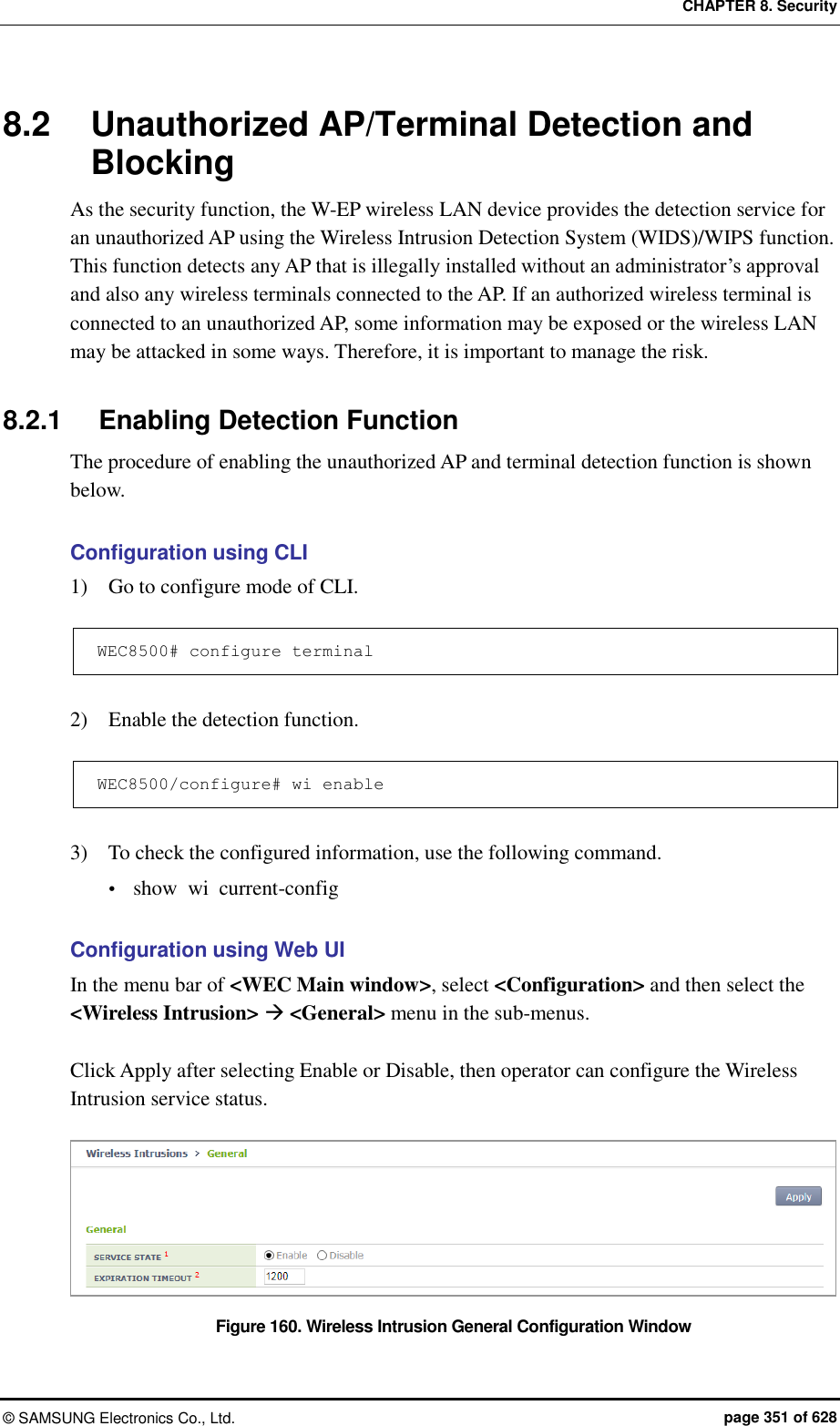
![CHAPTER 8. Security © SAMSUNG Electronics Co., Ltd. page 352 of 628 8.2.2 Detection The W-EP wireless LAN system detects all the packets in a wireless LAN network, classifies unauthorized APs and wireless terminals, and creates related alarms and logs. The detected unauthorized APs are classified as follows according to the configured classification policy. Classification type Description Managed AP AP that is allowed to be used by an administrator among the detected unauthorized APs - Configures the managed AP classification policy. - An administrator can classify a specific AP as a managed AP among the manually detected unauthorized APs. Unmanage AP AP that is not allowed to be used by an administrator among the detected unauthorized APs and AP that can be used maliciously - Configures the unmanaged AP classification policy. - An administrator can classify a specific AP as a unmanaged AP among the manually detected unauthorized APs. 8.2.2.1 Configuring the managed AP classification policy To configure the managed type authorized AP classification policy, execute the command as follows: Configuration using CLI 1) Go to configure wi device configuration mode of CLI. WEC8500# configure terminal WEC8500/configure# wi WEC8500/configure/wi# device WEC8500/configure/wi/device# 2) Configure the managed type authorized AP policy. add-classification-rule- managed [RULE_NAME] enable [PRIORITY] [SSID_TYPE] [SSID] Parameter Description RULE_NAME Classification policy name PRIORITY Priority number SSID_TYPE SSID type - managed-ssid: SSID that is used in an authorized AP that is connected to the APC. - user-configured-ssid [SSID]: Entered SSID (An AP that has SSID as SSID_NAME is classified as a friendly type unauthorized AP.)](https://usermanual.wiki/Samsung-Electronics-Co/WEA463E.Part-1/User-Guide-2696662-Page-352.png)
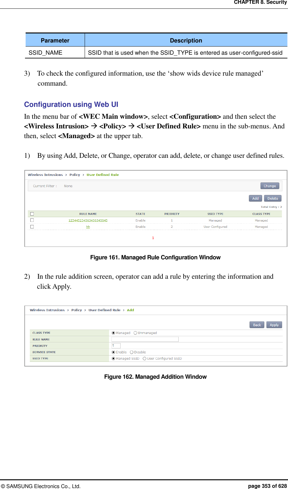
![CHAPTER 8. Security © SAMSUNG Electronics Co., Ltd. page 354 of 628 8.2.2.2 Configuring the unmanaged AP classification policy To configure the unmanaged type unauthorized AP classification policy, execute the command as follows: Configuration using CLI 1) Go to configure wi device configuration mode of CLI. WEC8500# configure terminal WEC8500/configure# wi WEC8500/configure/wi# device WEC8500/configure/wi/device# 2) Configure the unmanaged type unauthorized AP policy. add-classification-rule-unmanaged [RULE_NAME] enable [PRIORITY] [MATCH_TYPE] [MIN_RSSI] [MIN_DURATION] [NO_OF_MIN_ASSOC CLIENTS] [ENCRYPTION] [SSID_TYPE] [SSID] Parameter Description RULE_NAME Classification policy name PRIORITY Rule priority number MATCH_TYPE Enter either match-all or match-any. - match-all: Classifies as a unmanaged unauthorized AP when the detection criteria entered thereafter are all satisfied. - match-any: Classifies as a unmanaged unauthorized AP when any one of the detection criteria entered thereafter is satisfied. MIN_RSSI Minimum RSSI. When the RSSI value is higher than this value, it is classified as a unmanaged unauthorized AP. MIN_DURATION Minimum lasting time (unit: s). When the signal lasting time is higher than this value, it is classified as a unmanaged unauthorized AP. NO_OF_MIN_ASSOCCLIENTS Minimum number of connected terminals When the number of connected terminals is higher than this value, it is classified as a unmanaged unauthorized AP. ENCRYPTION Whether to use encryption - 0: Does not use encryption. If encryption is not used, it is classified as a unmanaged unauthorized AP. - 1: Uses encryption. If encryption is used, it is classified as a malicious unauthorized AP. SSID TYPE SSID type - managed-ssid: SSID that is used in an authorized AP that is connected to the APC. - user-configured-ssid [SSID]: Entered SSID (An AP that has SSID as SSID_NAME is classified as a friendly type unauthorized AP.) SSID_ NAME SSID that is used when the SSID_TYPE is entered as user-configured-ssid](https://usermanual.wiki/Samsung-Electronics-Co/WEA463E.Part-1/User-Guide-2696662-Page-354.png)