Samsung Electronics Co WIDT30Q WIFi Module User Manual S3025 W User Manual
Samsung Electronics Co Ltd WIFi Module S3025 W User Manual
UserManual.wiki
>
Samsung Electronics Co
>
WIDT30Q User Manual
>
User Manual Part 1
Contents
1.
Users Manual
2.
Manual
3.
User Manual
4.
User Manual Part 1
5.
User Manual Part 2
User Manual Part 1
Navigation menu
Upload a User Manual
Namespaces
Wiki Guide
HTML
PDF
Info
Views
User Manual
Discussion / Help
Navigation
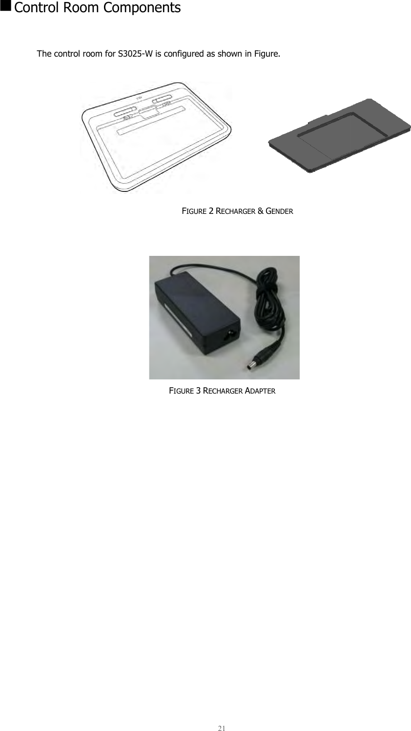
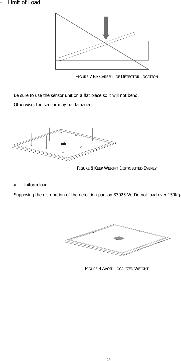
![ Product components Item 1 2 Power Supply Box3 Battery Recharger4 Battery Gender5 6 Recharger Adaptor7 1. Detector5. BatteryProduct components Part Name Qty Detector 1 Front view of the devicePower Supply Box 1 Source of necessary electricityBattery Recharger 1 To recharge an extra batteryBattery Gender 1 battery & battery rechargerBattery Pack 2 Source for wireless connectionRecharger Adaptor 1 Source of the batteryMain Cable 1 To connect xTable 3 6. Recharger Adapter Detector 2. Power Supply Box Battery pack 19 Description Front view of the device Source of necessary electricity To recharge an extra battery Bridge between battery & battery recharger Source for wireless connection Source of the battery pack recharger To connect x-ray detector with Power Supply Box COMPONENTS 3. Battery pack Recharger 7. Main Cable 4. Battery pack Recharger Comment [1]: DC 24V ](https://usermanual.wiki/Samsung-Electronics-Co/WIDT30Q.User-Manual-Part-1/User-Guide-2348080-Page-19.png)
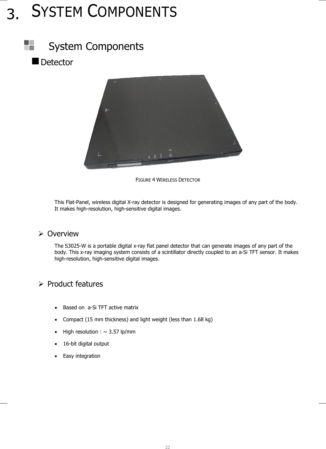
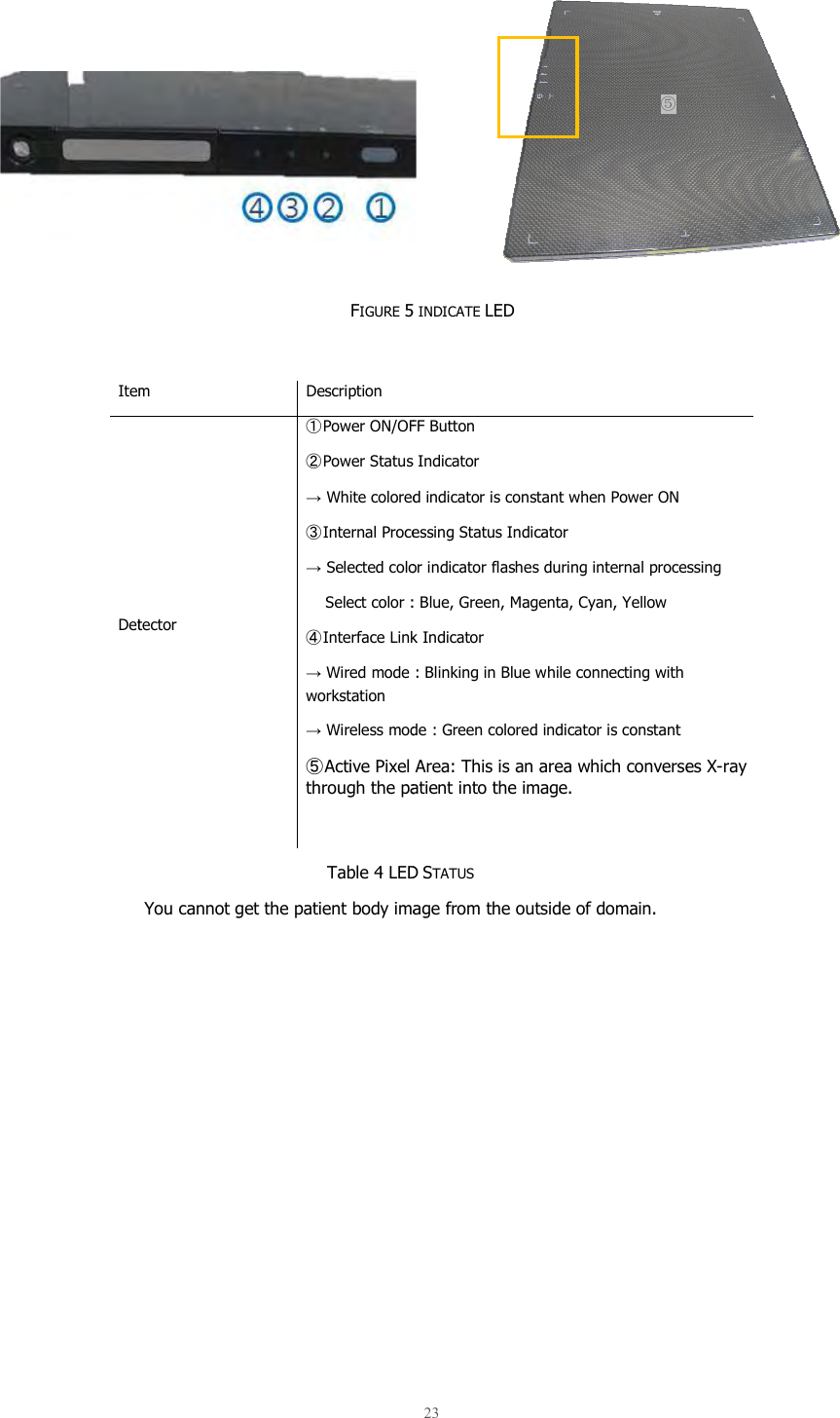
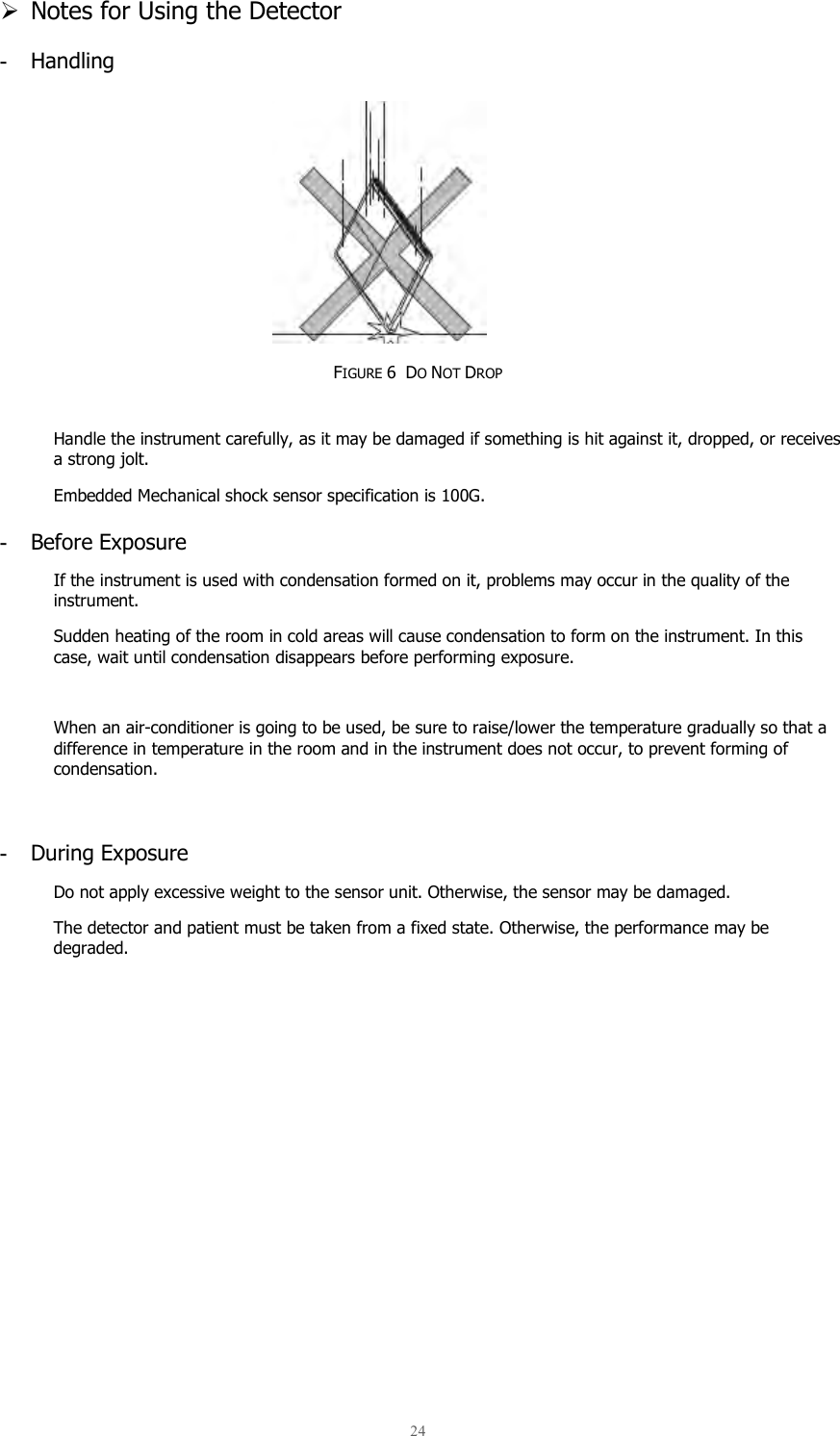
![ Examination The components of Components in accordance with their installation locations. The below figure 1 shows All examination room components of the system should be used inside a shielded environment. Examination Room ComponentsThe components of S3025-W can be divided into the examination room components and the control roomComponents in accordance with their installation locations.The below figure 1 shows S3025-W Examination Components Figure 1 EXAMINATION All examination room components of the system should be used inside a shielded environment.Detector 20 Components can be divided into the examination room components and the control roomComponents in accordance with their installation locations. Examination Components. XAMINATION ROOM COMPONENTS All examination room components of the system should be used inside a shielded environment.Power box Main cablecan be divided into the examination room components and the control room All examination room components of the system should be used inside a shielded environment. Main cable Comment [2]: DC 24V ](https://usermanual.wiki/Samsung-Electronics-Co/WIDT30Q.User-Manual-Part-1/User-Guide-2348080-Page-20.png)