Samsung Electronics Co WIP5001A WIP ADAPTOR User Manual A3LWIP5001A user manual
Samsung Electronics Co Ltd WIP ADAPTOR A3LWIP5001A user manual
UserManual.wiki
>
Samsung Electronics Co
>
WIP5001A User Manual
USERS MANUAL
Navigation menu
Upload a User Manual
Namespaces
Wiki Guide
HTML
PDF
Info
Views
User Manual
Discussion / Help
Navigation
![WIP-5001A Quick Installation Guide Before You Begin UniData Communication Systems Inc. Page 1 April 27, 2004 1. Before You Begin The best way to set the configuration is using a PC with LAN card installed. The factory default IP address for WIP-5001A is 192.168.1.100, and Subnet Mask is 255.255.255.0. Change the PC IP address to static (192.168.1.xxx) such as the WIP-5001A. 1.1 Setting the PC as Static IP Address Before connecting to setup-screen, change the PC IP to static. 1 Double-Click the [Start] -> [Setup] -> [Control Pannel] -> [Network Connection]. 2 [Local Area Connection] -> [Properties] -> [This connection uses the following items:]. Double-click the [TCP/IP] and enter the followings below. IP Address: 192.168.1.2 Subnet Mask: 255.255.255.0 Gateway Address: None 3 After entering all of the above, press [OK] button and finish the setting. (For Windows ME/98, PC needs to be restarted.) 2. Check Your Package Contents After purchasing the WIP-5001A, please check if the following items are included. WIP-5001A Wireless LAN Adaptor Ethernet (CAT 5 UTP/Straight Through) Cable 5V DC, 2A Power Adapter If any of the above items are missing, please contact your reseller. WIP-5001A POWER connecting jack must be connected with WIP-5001A adapter that came with. Using different type of adpater my cause serious damage to WIP-5001A.](https://usermanual.wiki/Samsung-Electronics-Co/WIP5001A/User-Guide-421692-Page-1.png)
![WIP-5001A Quick Installation Guide LED Status Indication UniData Communication Systems Inc. Page 3 April 27, 2004 4. LED Status Indication LED light on the WIP-5001A turns on/off depends on state. The followings explain the status of LED indication. 1. [PWR] indicates Power comes on. Red light sustains while power comes on. 2. [Link] indicates LAN Port’s Link (Connection)/Activity. Yellow light is up when the phone gets linked and LED blinks when transmitting the data. 3. [R/Tx] indicates Wireless LAN’s Link/Activity. Red light is up when it gets linked and LED blinks when transmitting the data.](https://usermanual.wiki/Samsung-Electronics-Co/WIP5001A/User-Guide-421692-Page-3.png)
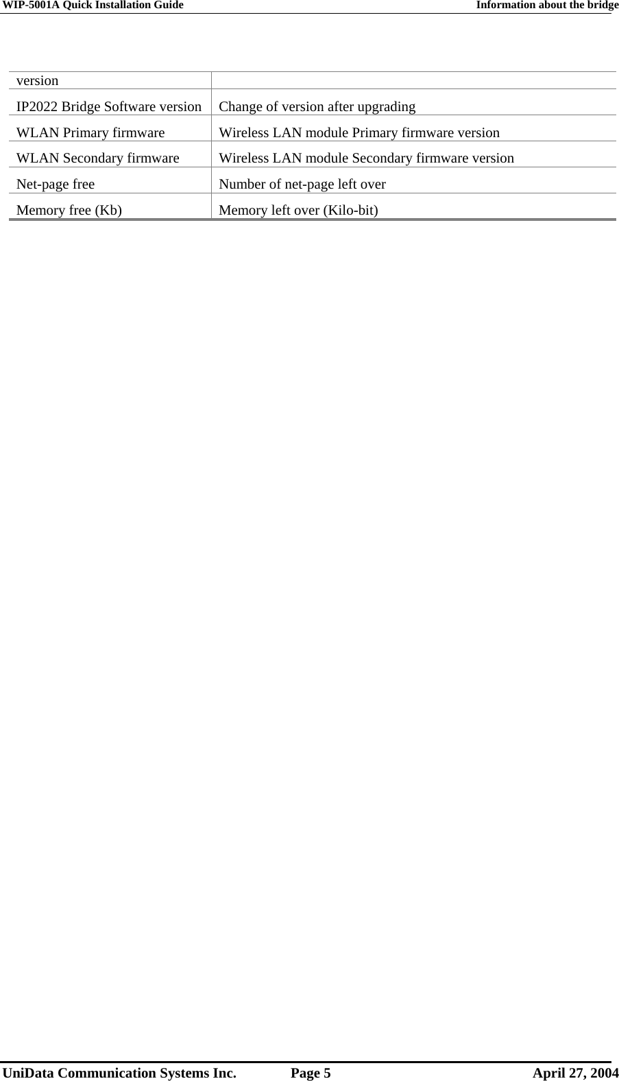
![WIP-5001A Quick Installation Guide Information about the bridge UniData Communication Systems Inc. Page 4 April 27, 2004 5. Information about the bridge When [Information] Menu has selected, user can look up the setup information of Access Point WIP-5001A version. Here are the Information contents. Contents Description Connected to SSID SSID that WIP-5001A is connected to Using channel Channel that are currently using MAC address of Access Point Connected Access Point’s MAC address Current transmission rate (Mbit/s) Connection speed (1, 2, 5.5, 11Mbit/s) Current communication quality (%) Signal Strength is shown in %. Non-IP MAC address Generally use “FFFFFFFFFFFF” MAC address of the wireless card WIP-5001A’s MAC address IP2022 Bridge Firmware Basic stack version](https://usermanual.wiki/Samsung-Electronics-Co/WIP5001A/User-Guide-421692-Page-4.png)
![WIP-5001A Quick Installation Guide Wireless Configuration UniData Communication Systems Inc. Page 6 April 27, 2004 6. Wireless Configuration From this chapter, the SSID means 6 numbers that is registered in SYSTEM ID of iDCS 500 MMC [845]. Run the web browser. Enter “http://192.168.1.100” at URL address box and press [Enter] button. Then Logon screen shows up like the screen on the right. Enter “User Name: admin, Password: admin” and press [OK] button. Then Information screen shows up like the screen on the right. Click the [Wireless] menu and wait for a few second.](https://usermanual.wiki/Samsung-Electronics-Co/WIP5001A/User-Guide-421692-Page-6.png)
![WIP-5001A Quick Installation Guide Wireless Configuration UniData Communication Systems Inc. Page 7 April 27, 2004 Then Wireless Configuration screen shows up like the screen on the right. Check if Operating Mode is set to Infrastructure, and enter The SSID: Samsung WBS24’s ESS-ID. (Basically SSID is registered with “123456”.) From the Logon screen, check mark on [Save this password in your passward list] then password won’t be asked next time. When the Information screen doesn’t show up in 5 seconds, press F5 key to refresh the page.](https://usermanual.wiki/Samsung-Electronics-Co/WIP5001A/User-Guide-421692-Page-7.png)
![WIP-5001A Quick Installation Guide Wireless Configuration UniData Communication Systems Inc. Page 8 April 27, 2004 After done entering ESS-ID, click [Save] button. Then Dialog Box will pop up just like the screen on the right. Click [OK] button. In a moment Information screen will be on. See if ESS-ID you entered is shown correctly. If it is correct, basic setup is finished. The SSID: When menu has left empty, WIP-5001A will connects to Access Point that has the greatest Signal Strength and it might not work.](https://usermanual.wiki/Samsung-Electronics-Co/WIP5001A/User-Guide-421692-Page-8.png)
![WIP-5001A Quick Installation Guide Security Configuration UniData Communication Systems Inc. Page 9 April 27, 2004 7. Security Configuration WIP-5001A can supports WEP: Wireless LAN security protocol when the Access Point’s WEP KEY is set. Click the [Wireless] menu. WEP enabled: Click the check box WEP Key Length: select WEP key bits between 64bits and 128bits. Enter the hexadecimal at WEP Key1. (Usually AP supports 4 WEP keys available.) WEP key to use: select which WEP Key is going to be used.](https://usermanual.wiki/Samsung-Electronics-Co/WIP5001A/User-Guide-421692-Page-9.png)
![WIP-5001A Quick Installation Guide Security Configuration UniData Communication Systems Inc. Page 10 April 27, 2004 Deny unencrypted data: Click the check box. Shared Key Authentication: Click the check box. Lastly, click the [Save] button. Then dialog box will pop up just like the screen on the right. Click [OK] button. WEP is abbreviation for Wired Equivalent Privacy, which is the algorithm to support the Privacy corresponding to LAN. By setting the WEP Key, it denies the access from unapproved network. WIP-5001A supports 64/128bits of WEP Key.](https://usermanual.wiki/Samsung-Electronics-Co/WIP5001A/User-Guide-421692-Page-10.png)
![WIP-5001A Quick Installation Guide Software Upgrade UniData Communication Systems Inc. Page 11 April 27, 2004 8. Software Upgrade Software Upgrade is used for the functional improvement of WIP-5001A’s software hereafter. PC must have upgrade file (bin type). Click the [Upgrade] menu. Either enters the whole directory route with the file name or click the [Browse…] button to search the file then click [Open] button. Click Press button. (Press to upload the file!)](https://usermanual.wiki/Samsung-Electronics-Co/WIP5001A/User-Guide-421692-Page-11.png)
![WIP-5001A Quick Installation Guide Software Upgrade UniData Communication Systems Inc. Page 12 April 27, 2004 As shown in the screen on the right, Check if it gives an upgrade complete message. Pressing F5 key moves to first [Information] screen. After done upgrading, do the followings. Click [Start] -> [Setup] -> [Control Panel] and run the [Internet Option]. At “General” tab, click Temporary Internet File -> Delete Files. Otherwise screen will look different. While upgrading WIP-5001A, do not turn off the power.](https://usermanual.wiki/Samsung-Electronics-Co/WIP5001A/User-Guide-421692-Page-12.png)
![WIP-5001A Quick Installation Guide Restore to Factory Defaults UniData Communication Systems Inc. Page 13 April 27, 2004 9. Restore to Factory Defaults This is a function that restores the WIP-5001A to Factory Default. This is very useful function when the password has forgotten or user has changed. Operates at Web Browser Login screen or WIP-5001A’s web page. 9.1 Web Browser Login screen From the Login screen, enter the “User Name: admin, Password: restore” and press [OK] button then it resets to Factory default. After reset to default, enter “User Name: admin, Password: admin” at Web setup screen. 9.2 Using the web page As shown in the screen below, go to [Admin] menu then click Restore to factory defaults button. User password can be changed in [Admin] menu. Please make a note of password that has changed.](https://usermanual.wiki/Samsung-Electronics-Co/WIP5001A/User-Guide-421692-Page-13.png)