Samsung SDS SAM-CRM-13 UNI-PAY User Manual HW SPEC SAM CRM 13 121024
Samsung SDS Co., Ltd. UNI-PAY HW SPEC SAM CRM 13 121024
User Manual
Revision Date Document Name Document Number Page
A4 2012.06.11 SAM-CRM-13 H/W Spec. 1 of 9
SAM-CRM-13 (Validator RF) Board
H/W S
p
ecification
2012. 06. 20
Duali
______________________________
Project Manager
___________________________
Approved
Revision Date Document Name Document Number Page
A4 2012.06.11 SAM-CRM-13 H/W Spec. 2 of 9
Revision History
Version Date Author Verifier Description

Revision Date Document Name Document Number Page
A4 2012.06.11 SAM-CRM-13 H/W Spec. 3 of 9
1 Overview
SAM-CRM-13 is a high-end RF reader and it is the world first device which supports all
three specification as following, (1) Conrtactless card spec_Mifare, ISO14443 Standard
A/B, (2)Payment spec_Paywave, Paypass, JSMART, American Express and (3) EMVCo Type
Approval Contact less Level 1 , NFC forum spec complaint.
It also has 8(EA) of SIM slot for secure communication, RS-232(2ea) as interface method.
1) Purpose (Use)
It is multi-purpose smartcard reader mainly use for credit card transaction at auto-
gate at subway station or automatic ticket vending machine
2) Communication & Operation
It controls credit card transaction by sending command to Host Controller via RS232.
This terminal operates LED and Buzzer of the transaction operating and result.
The operation of LED & Buzzer can be different by each specification (refer to the
Paypass, JSMART, American Express specification for detail information)
3) RF interface
①. Conrtactless card spec_Mifare,
②. ISO14443 Standard A/B
4) SAM interface
It is designed to capable of communicating SAM (ISO 7816 ) by attaching extended
parts for future use.
Revision Date Document Name Document Number Page
A4 2012.06.11 SAM-CRM-13 H/W Spec. 4 of 9
2 Summary
ITEM Specification Description
CPU STM32F417ZGT6 (ARM Cortex_M4, 144pin) ST
Program Memory 1MBytes FLASH (default)
Up to 8Mbytes external Flash(Basically 4M
byte)
On chip
Option
(1M,2M,4M,8M)
Data Memory 192KBytes SRAM (default)
Up to 8Mbytes external SRAM(Basically 512K
byte)
On chip
Option
(1M,2M,4M,8M)
DISPLAY 4 Status LED
Communication RS-232 * 2 Decide when order
BUZZER Magnetic Buzzer
RF CARD Frequency : 13.56MHz
Speed : 106,212,424,848Kbps
ISO-14443 A/B ,MIFARE
SAM 4 SAM slots (optional 4 SAM slots)
Class A and B, T=0 and T=1
Input Power DC 12V
Revision Date Document Name Document Number Page
A4 2012.06.11 SAM-CRM-13 H/W Spec. 5 of 9
3 Structure
The Structure of equipment
- SAM-CRM-13 itself contains all circuits include antenna, 8 SAM connectors.
Description of SAM-CRM-13
CPU: 32bit RISC ARM core CPU, It is stm32f417 which is ARM-based 32-bit MCU
with Flash, This CPU has 1Mbyte Flash memory, 192Kbyte SRAM.
PN512 RF IC: This RF IC can control RF card like MIFARE card, type A/B card,
Felica, simultaneously.
RS-232 Driver: It’s a Communication part for RS-232 communication.
SAM part: It can control 8 SAMs for multi purpose. Each SAM slot can be
operated independently and they don’t affect the transmitted signal.
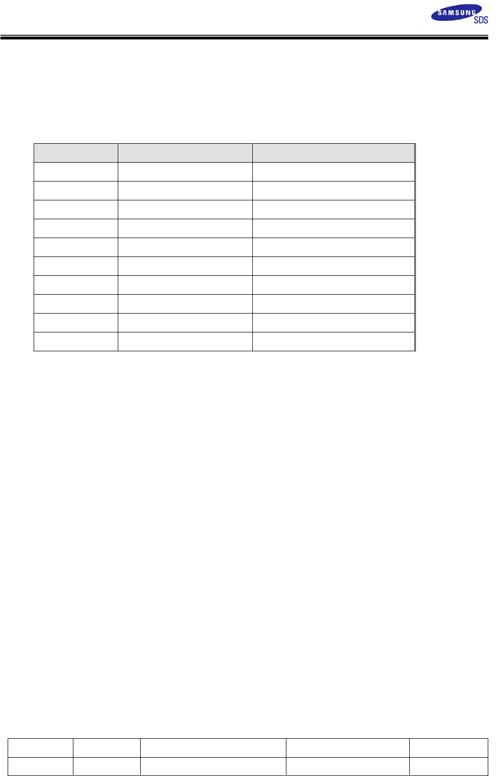
LED: It has 4 LEDs to display status of communication and card process.
- Ready : Blue
- Process : Yellow
- Complete : Green
- Error : Red
Battery: It maintains RTC and battery backup SRAM while power is not
supplied.
Tamper switch: Erase security memory when case is opened.
SRAM : optional SRAM for user memory.
Reset : External reset
Buzzer : Displays transaction status (success result/ error). Detail
operation is defined by each Payment specification.
Host Controller
(RS-232)
Revision Date Document Name Document Number Page
A4 2012.06.11 SAM-CRM-13 H/W Spec. 6 of 9
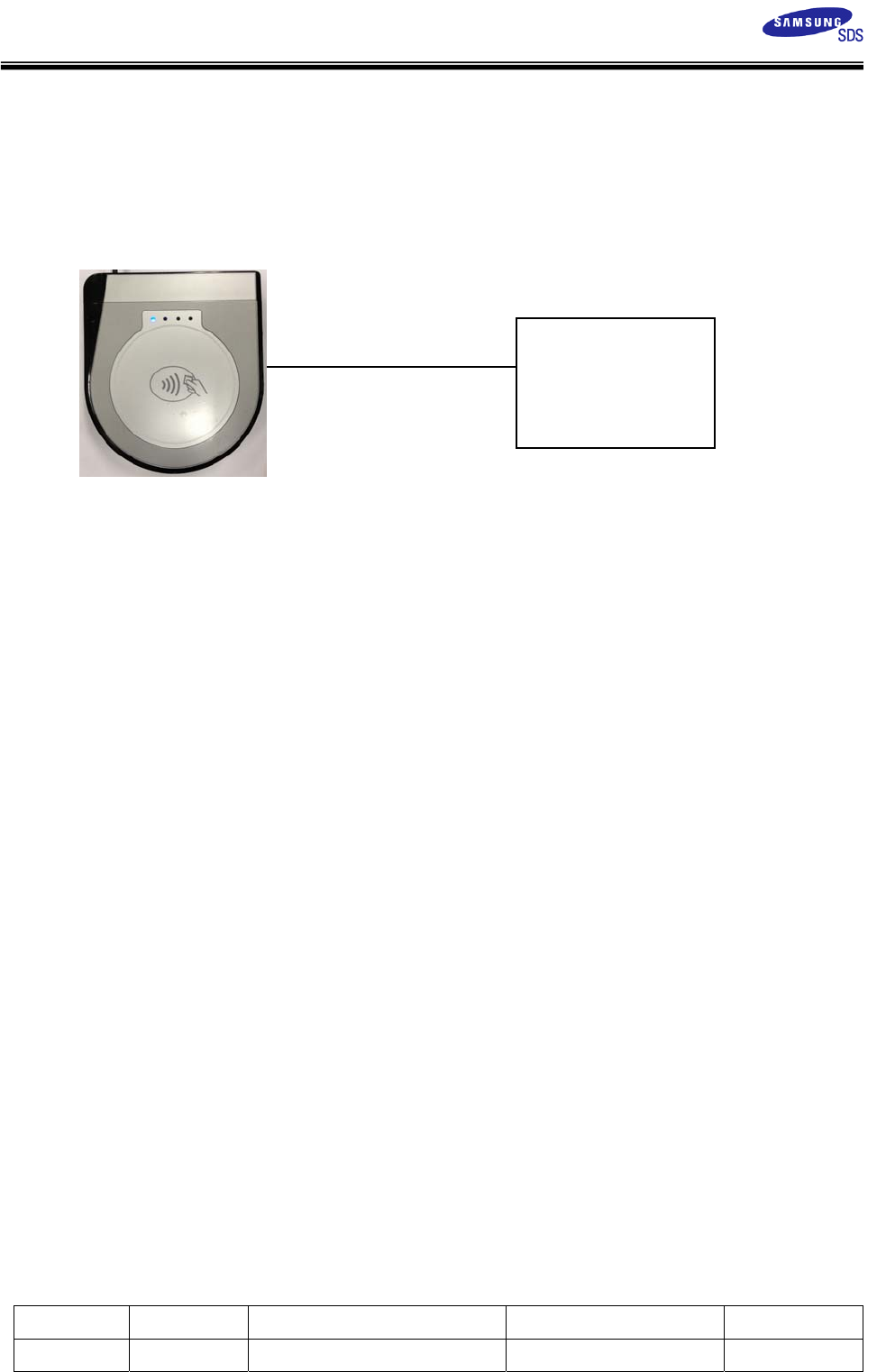
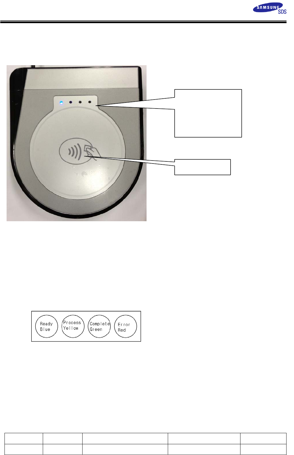
4 Description of Surface
The picture of device surface
Communication Cable
Serial cable
The size of terminal
135.5(W) * 152.7(L) * 29(H)mm
LED configuration
RF Card zone
Blue - Ready
Yellow - Process
Green - Complete
Red - Error
Revision Date Document Name Document Number Page
A4 2012.06.11 SAM-CRM-13 H/W Spec. 7 of 9
5 Connector Pin Assignment
RS-232 Connector and Cable
Pin No Description
1 PWR_IN DC 12V
2 GND
3 TX1_RS232 For Host Controller
4 RX1_RX232 For Host Controller
5 GND
6 TX2_RS232 For slave
7 RX2_RX232 For slave
8 IO
9 RESET+
10 RESET-
Revision Date Document Name Document Number Page
A4 2012.06.11 SAM-CRM-13 H/W Spec. 8 of 9
6 Description of Electricity
The Description of power
- Input power : 12V
The using electric current
- Normal 12V, 130mA under
- MAX 12V, 300mA under
The Description of Serial communication
- 115200bps, 8 data, no parity, 1 stop bit
7 Description of Function
Protocol Specification
Refer to protocol specification for detail function. ( provide on request)
Control Code Specification
Refer to control code specification for detail function. (provide on
request)
Firmware Download
Refer download manual. (provide on request)
8 Property
Operating Condition
- Temperature to use : -10 ~ 60 ℃
- Humidity to use : 30 ~ 90 % (relative humidity)
Storage Condition
- Temperature to keep : -20 ~ 80 ℃
- Humidity to use : 30 ~ 90 % (relative humidity)
9 Warning and Notice
- For indoor use only.
- This product is affected by an element like metal or Magnetism. So one has to
take precautions.
Revision Date Document Name Document Number Page
A4 2012.06.11 SAM-CRM-13 H/W Spec. 9 of 9
10 Certifications
EU
This product is CE marked according to the provision of the R&TTE Directive
(99/5/EC). Here by DUALi Inc. declares that this product is in compliance with the
essential requirements and other relevant provisions of Directive 1999/5/EC.
FCC STATEMENT
CAUTION: Changes or modifications not expressly approved by the party responsible
for compliance could void the user's authority to operate the equipment.
NOTE: This equipment has been tested and found to comply with the limits for a Class
B digital device, pursuant to Part 15 of the FCC Rules. These limits are designed to
provide reasonable protection against harmful interference in a residential
installation. This equipment generates, uses and can radiate radio frequency energy
and, if not installed and used in accordance with the instructions, may cause
harmful interference to radio communications. However, there is no guarantee that
interference will not occur in a particular installation. If this equipment does
cause harmful interference to radio or television reception, which can be determined
by turning the equipment off and on, the user is encouraged to try to correct the
interference by one or more of the following measures:
-- Reorient or relocate the receiving antenna.
-- Increase the separation between the equipment and receiver.
-- Connect the equipment into an outlet on a circuit different from that to which
the receiver is connected. -- Consult the dealer or an experienced radio/TV
technician for help.