Samsung SDS SAM-OCU-14 OCU (On-board Control Unit) User Manual
Samsung SDS Co., Ltd. OCU (On-board Control Unit)
User Manual

On board Control Unit
SAM-OCU-14
System Manual Ver 1.2
SAM-OCU-14_MANUAL
Rev. 1.2
Dec. 05, 2013
Copyright ⓒ 2013 Samsung SDS Co., Ltd. All rights reserved. You are strictly prohibited to copy, disclose, distribute, or use
this document in part or as a whole for any purposes other than those for which this document is disclosed. This document is
copyrighted and contains confidential information and other intellectual property rights of Samsung SDS Co., Ltd. Any
unauthorized use, copy, disclosure or distribution constitutes infringement of Samsung SDS’ intellectual property rights.
System Manual – SAM-OCU-14 – 2013.12.05
Copyright ⓒ 2013 Samsung SDS Co., Ltd. All rights reserved | Confidential
Revision History
Document Name
On board Control Unit System Manual
Version
Date
Notice
Writer
0.1
1.0
1.1
1.2
2013.06.20
2013.11.14
2013.11.18
2013.12.05
Draft
Revision
Revision & Translation
Revision
Kihyun, Kim
Dalyoung, Kim
Kihyun, Kim
Dalyoung, Kim
System Manual – SAM-OCU-14 – 2013.12.05
Copyright ⓒ 2013 Samsung SDS Co., Ltd. All rights reserved | Confidential
CONTENTS
Table of Contents
1 OVERVIEW .............................................................................................................................................. - 4 -
1.1 GENERAL DESCRIPTION ....................................................................................................................... - 4 -
1.2 OUTSIDE DIMENSION ........................................................................................................................... - 4 -
1.3 SYSTEM CONFIGURATION .................................................................................................................... - 6 -
1.3.1
Block Diagram............................................................................................................................ - 6 -
1.4 GENERAL SPECIFICATION ..................................................................................................................... - 7 -
2 MODULE CONFIGURATION ............................................................................................................... - 8 -
2.1 CPU MODULE ...................................................................................................................................... - 8 -
2.1.1
General Description .................................................................................................................... - 8 -
2.1.2
Block diagram ............................................................................................................................ - 9 -
2.2 BASE BOARD MODULE ........................................................................................................................ - 10 -
2.2.1
General Description ................................................................................................................. - 10 -
2.2.2
Layout of Base board module .................................................................................................. - 10 -
2.2.3
Wi-Fi/Bluetooth module ........................................................................................................... - 11 -
2.2.4
GPS module .............................................................................................................................. - 11 -
2.3 TOUCH SCREEN DISPLAY ................................................................................................................... - 11 -
2.3.1
General Description ................................................................................................................. - 11 -
2.3.2
Layout ....................................................................................................................................... - 12 -
2.3.3
LCD display specification ........................................................................................................ - 13 -
2.3.4
Touch panel Specification ........................................................................................................ - 13 -
2.4 SPEAKER ............................................................................................................................................ - 14 -
2.4.1
General Description ................................................................................................................. - 14 -
2.5 CONNECTOR AND POWER SWITCH ...................................................................................................... - 15 -
2.5.1
Signal & Power connector ....................................................................................................... - 15 -
2.5.2
LAN connector ......................................................................................................................... - 15 -
2.5.3
Power switch & Fuse holder .................................................................................................... - 16 -
2.6 CONNECTION DIAGRAM ....................................................................................................................... - 0 -
2.6.1
Rear Cover connector – PWR .................................................................................................... - 0 -
2.6.2
Rear Cover connector –SIGNAL ............................................................................................... - 1 -
2.6.3
Rear Cover connector –DIO ....................................................................................................... - 1 -
2.7 OPERATION & USAGE .......................................................................................................................... - 2 -

System Manual – SAM-OCU-14 – 2013.12.05
Copyright ⓒ 2013 Samsung SDS Co., Ltd. All rights reserved | Confidential
List of Tables
TABLE 1 GENERAL SPECIFICATION ....................................................................................................................... - 7 -
TABLE 2 SPECIFICATION OF GPS MODULE .......................................................................................................... - 11 -
TABLE 3 SPECIFICATION OF LCD DISPLAY ......................................................................................................... - 13 -
TABLE 4 SPECIFICATION OF TOUCH PANEL ......................................................................................................... - 13 -
TABLE 5 SPECIFICATION OF SPEAKER ................................................................................................................. - 14 -
TABLE 6 SPECIFICATION OF PWR CONNECTOR .............................................................................................. - 13 -
TABLE 7 SPECIFICATION OF SIGNAL CONNECTOR ........................................................................................ - 13 -
TABLE 8 SPECIFICATION OF DIO CONNECTOR ............................................................................................... - 13 -
List of Figures
FIGURE 1 DRAWING OF OCU ............................................................................................................................... - 4 -
FIGURE 2 OUTSIDE DIMENSION ............................................................................................................................ - 5 -
FIGURE 3 OCU BLOCK DIAGRAM ........................................................................................................................ - 6 -
FIGURE 4 BLOCK DIAGRAM OF CPU MODULE ..................................................................................................... - 9 -
FIGURE 5 TOP LAYOUT OF BASE BOARD MODULE (EXAMPLE) ........................................................................... - 10 -
FIGURE 6 BOTTOM LAYOUT OF BASE BOARD MODULE (EXAMPLE) .................................................................... - 10 -
FIGURE 7 LAYOUT OF LCD DISPLAY .................................................................................................................. - 12 -
FIGURE 8 LAYOUT OF TOUCH PANEL .................................................................................................................. - 12 -
FIGURE 9 LAYOUT OF SPEAKER.......................................................................................................................... - 14 -
FIGURE 10 CONNECTOR LAYOUT OF REAR COVER .............................................................................................. - 0 -
System Manual – SAM-OCU-14 – 2013.12.05
Copyright ⓒ 2013 Samsung SDS Co., Ltd. All rights reserved | Confidential
1 Overview
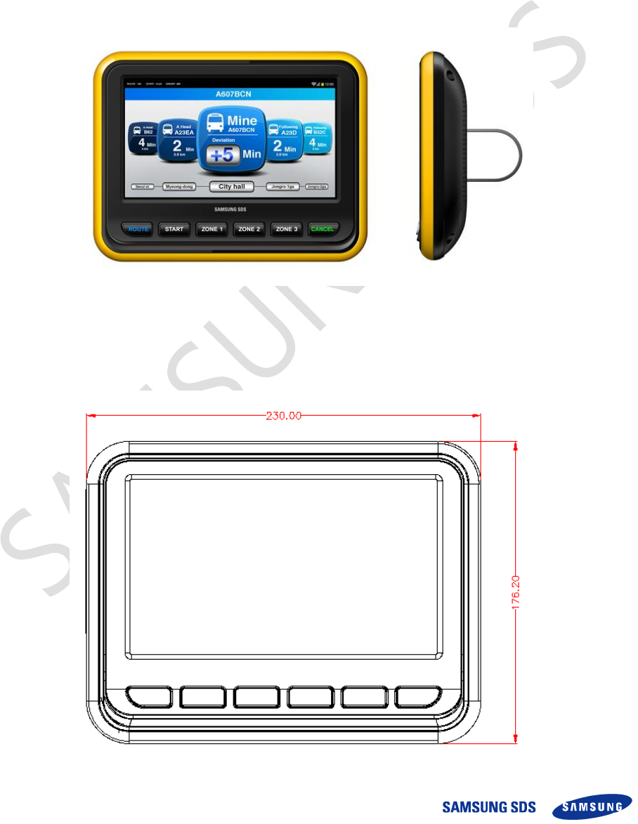
1.1 General Description
On-board Control Unit (OCU) is installed in a bus. That controls the bus system (such as
door, passenger information display and etc.) and ticket validating system. In addition, it
has a function of communication with the external center server.
This document informs and defines each module and specification of OCU.
Figure 1 Drawing of OCU
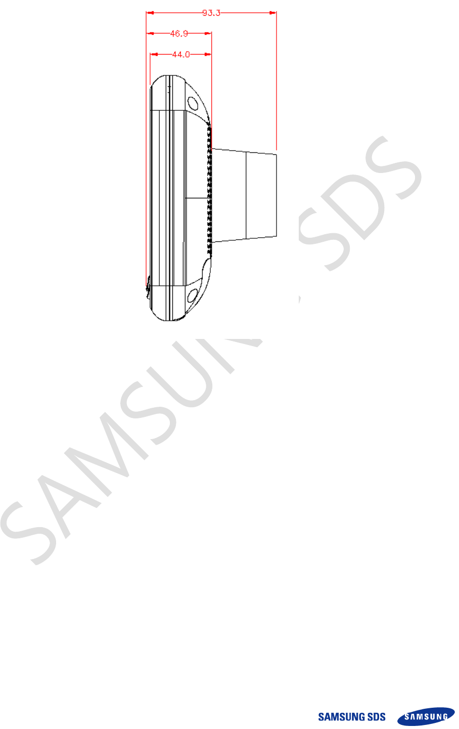
1.2 Outside Dimension
System Manual – SAM-OCU-14 – 2013.12.05
Copyright ⓒ 2013 Samsung SDS Co., Ltd. All rights reserved | Confidential
Figure 2 Outside dimension
System Manual – SAM-OCU-14 – 2013.12.05
Copyright ⓒ 2013 Samsung SDS Co., Ltd. All rights reserved | Confidential
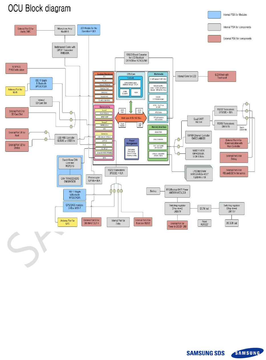
1.3 System Configuration
1.3.1 Block Diagram
The following figure is the OCU block diagram.
Figure 3 OCU Block Diagram
System Manual – SAM-OCU-14 – 2013.12.05
Copyright ⓒ 2013 Samsung SDS Co., Ltd. All rights reserved | Confidential
1.4 General Specification
The table below shows the general specifications of the OCU.
System
Item
Specification
Enclosure
Dimension(mm)
230.0(W) * 176.2(H) * 46.9(D)
Material
Outside steel of enclosure :
Material: PC-ABS
CPU Module
Processor
Samsung S5PV210, Cortex-A8 1GHz
Memory
RAM: 512MB, NAND Flash: 512MB
OS
ANDROID 4.0
Base Board Module
Wi-Fi/Bluetooth Module
IEEE802.11b/g/n, Bluetooth 3.0+HS
GPS module
GPS RX Sensitivity: -164dBm
GPS Accuracy: 3m
Touch screen display
8 inch
Resolution: 1024 * 3(RGB) * 600
Touch method: 4-wire resistive touch
External Interface
USB 2.0 Host * 1
USB 2.0 OTG * 1
SD Card Slot * 1
LAN * 1
RS232 * 1, RS232/485 * 1
CAN interface * 1
Antenna port *3
Speaker
Rated Input Power
1W, 8ohm
Power
Input voltage (V)
24 VDC
Table 1 General specification

System Manual – SAM-OCU-14 – 2013.12.05
Copyright ⓒ 2013 Samsung SDS Co., Ltd. All rights reserved | Confidential
2 Module Configuration
The configuration of OCU is as follows:
CPU Module
Base Board Module
Touch Screen Display
Speaker
2.1 CPU Module
2.1.1 General Description
The CPU Module controls all the sub-modules and processes all the data in the OCU.
They have sufficient space for Operating System (OS) and the OCU application data.
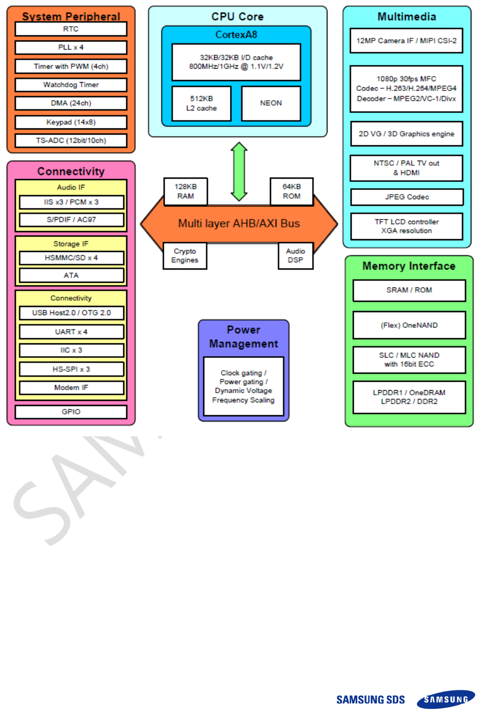
CPU Module is assembled with some parts as follows;
- CPU (Samsung S5PV210, Cortex-A8 1GHz)
- RAM (LDDR2 1Gbit *4)
- NAND Flash 512MB
System Manual – SAM-OCU-14 – 2013.12.05
Copyright ⓒ 2013 Samsung SDS Co., Ltd. All rights reserved | Confidential
2.1.2 Block diagram
Figure 4 Block diagram of CPU Module
System Manual – SAM-OCU-14 – 2013.12.05
Copyright ⓒ 2013 Samsung SDS Co., Ltd. All rights reserved | Confidential
2.2 Base board module
2.2.1 General Description
Base board module performs major functions of OCU device controlling. The Wi-Fi/BT
module, CAN module and etc. are installed on the base board.
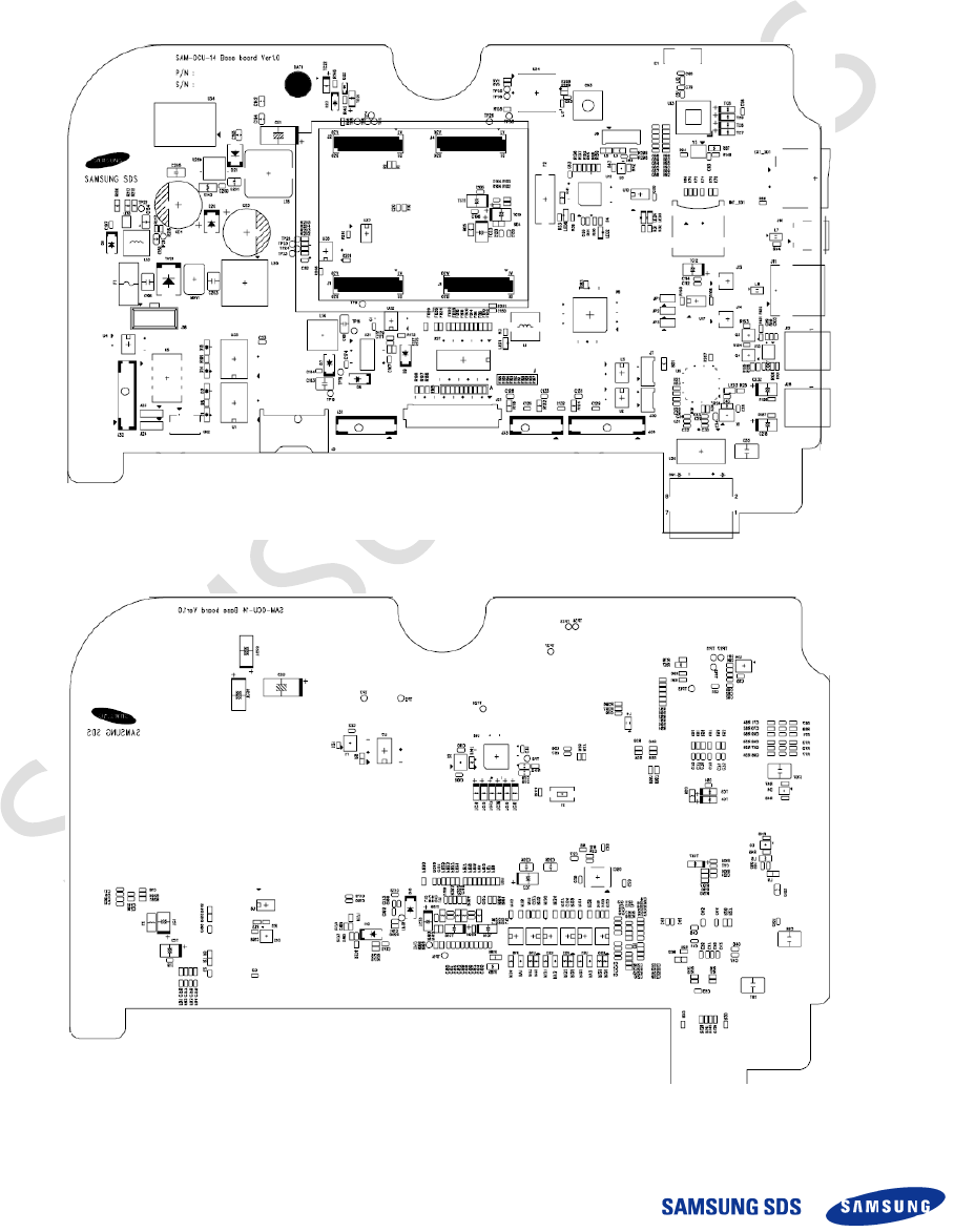
2.2.2 Layout of Base board module
Figure 5 Top Layout of Base board module (Example)
Figure 6 Bottom Layout of Base board module (Example)
System Manual – SAM-OCU-14 – 2013.12.05
Copyright ⓒ 2013 Samsung SDS Co., Ltd. All rights reserved | Confidential
2.2.3 Wi-Fi/Bluetooth module
The OCU has the Wi-Fi/Bluetooth module to communicate with the server (in the garage)
and peripheral devices. The key features are as below;
IEEE802.11b/g/n standard conformity, BT3.0,2.1+EDR
Low standby current (with advanced power save and sleep mode)
Transmit speed : 11/5.5/2/1 Mbps(11b), 54/48/36/24/18/12/9/6 Mbps(11g),
150~6.5 Mbps (11n)
Channel Number : 1 to 13 channel (11bg), 79 channel (BT)
Interface : SDIO
Built-in EEPROM, 2G-PA, Crystal, BPF
Security: WEP (64/128), TKIP, AES, WPA/WPA2, WAPI
Small Outline: 9.0 x 8.8 x 1.35(Max) mm
Package: Metal case package
Utilizes 88W8787 IC
RoHS Conformity
2.2.4 GPS module
The specification of GPS module is as below.
Item
Specification
RX Sensitivity
-164dBm
Cold start autonomous
-147dBm
Hot start autonomous
-161dBm
Tracking mode
-166dBm
Accuracy
3m
TTFF from cold start
42 sec
TTFF from warm start
30 sec
TTFF from hot start
1.8 sec
Table 2 Specification of GPS module
2.3 Touch Screen Display
2.3.1 General Description
The Touch screen display is a color graphic touch screen (8” inch TFT LCD) that allows
driver to input their operation. The Touch screen display is positioned ergonomically for
driver to operate easily.
System Manual – SAM-OCU-14 – 2013.12.05
Copyright ⓒ 2013 Samsung SDS Co., Ltd. All rights reserved | Confidential
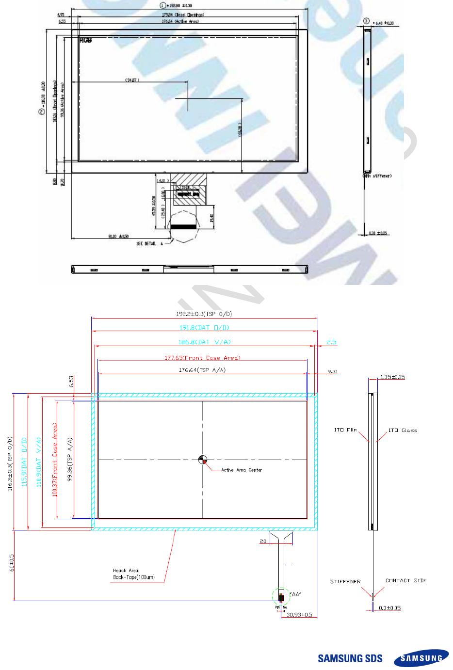
2.3.2 Layout
Figure 7 Layout of LCD display
Figure 8 Layout of Touch panel
System Manual – SAM-OCU-14 – 2013.12.05
Copyright ⓒ 2013 Samsung SDS Co., Ltd. All rights reserved | Confidential
2.3.3 LCD display specification
Item
Specification
LCD size
8.0 inch(Diagonal)
Driver element
a-Si TFT active matrix
Resolution
1024 x 3(RGB) x 600
Display mode
Normally White
Dot pitch
0.1725(W) x 0.1656(H)
Active area
176.64(W) x 99.36(H)mm
Module size
192.8(W) x 116.9(H) x 6.4(D)mm
Surface treatment
Plain
Color arrangement
RGB-stripe
View Direction(Gray
Inversion)
6:00 O’ Clock
Interface
Digital
Backlight power
consumption
3.56W (Typ.)
Panel power consumption
0.39 W(Typ)
Weight
0.226kg(Typ)
Table 3 Specification of LCD display
2.3.4 Touch panel Specification
Item
Specification
Glass THK
1.1mm
Film type
Non-glare
Total THK
1.35±0.15mm
Linearity
±1.5% or less
Transmittance
80% or more
Resistance
100 < X axis <1200ohm, 100 < Y axis < 1200ohm
Tail
FPC (Ni+Au)
Method
4-wire resistive touch
Table 4 Specification of Touch panel
System Manual – SAM-OCU-14 – 2013.12.05
Copyright ⓒ 2013 Samsung SDS Co., Ltd. All rights reserved | Confidential
2.4 Speaker
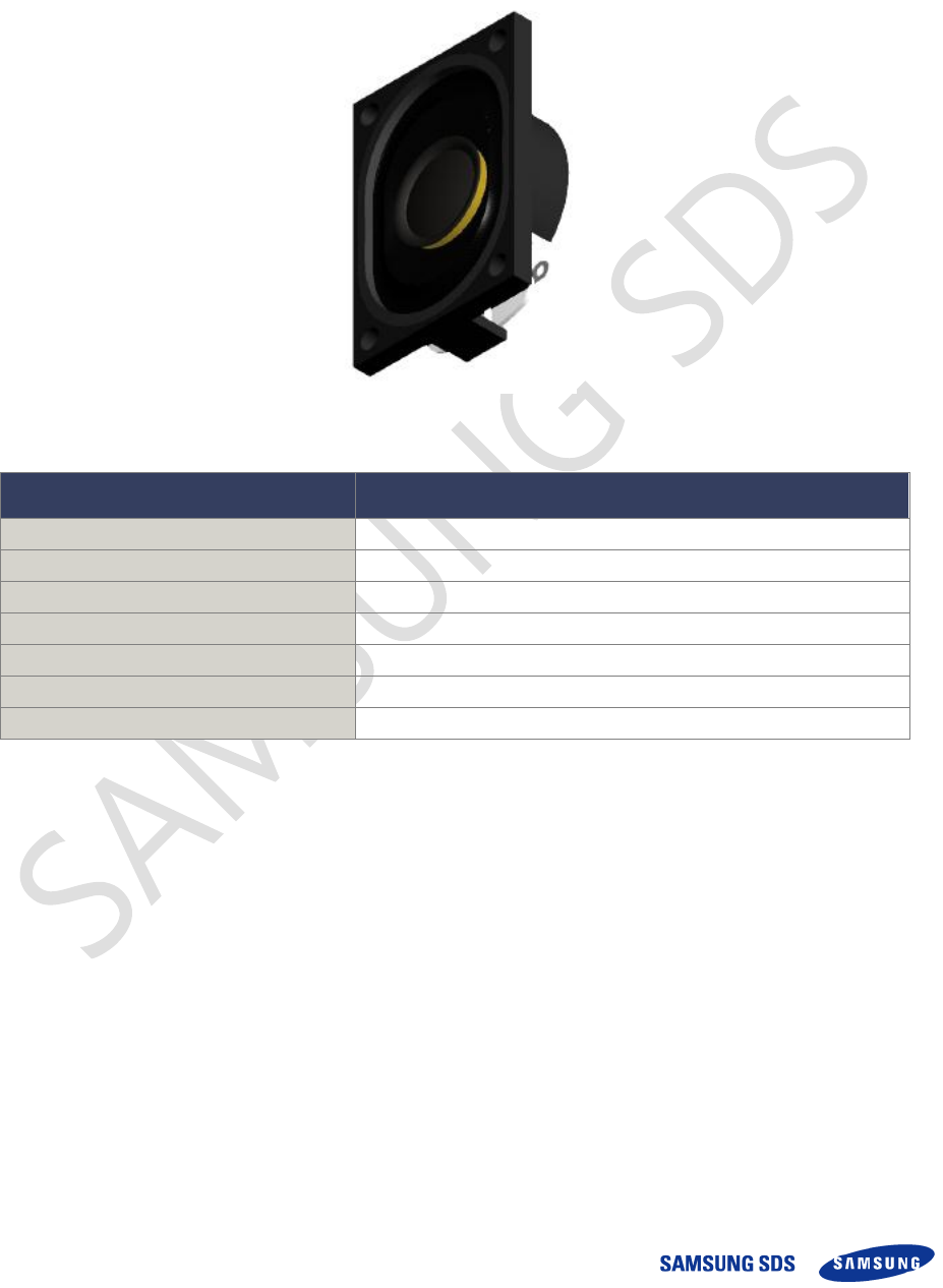
2.4.1 General Description
The Speaker is installed in the OCU. The speaker makes a sound for driver’s recognition.
Figure 9 Layout of Speaker
Items
Description
Rated Input Power
1.0W (Max. 1.5W)
Impedance
8±15%(Ohm)
Output SPL @ 0.1W/0.1M
87±2dB
Resonant frequency
800±20% Hz
Magnet size (mm)
11.5 * 1.5
Weight
10g
Dimension (mm)
40(W) * 20(H) * 8.2(D)
Table 5 Specification of Speaker
System Manual – SAM-OCU-14 – 2013.12.05
Copyright ⓒ 2013 Samsung SDS Co., Ltd. All rights reserved | Confidential
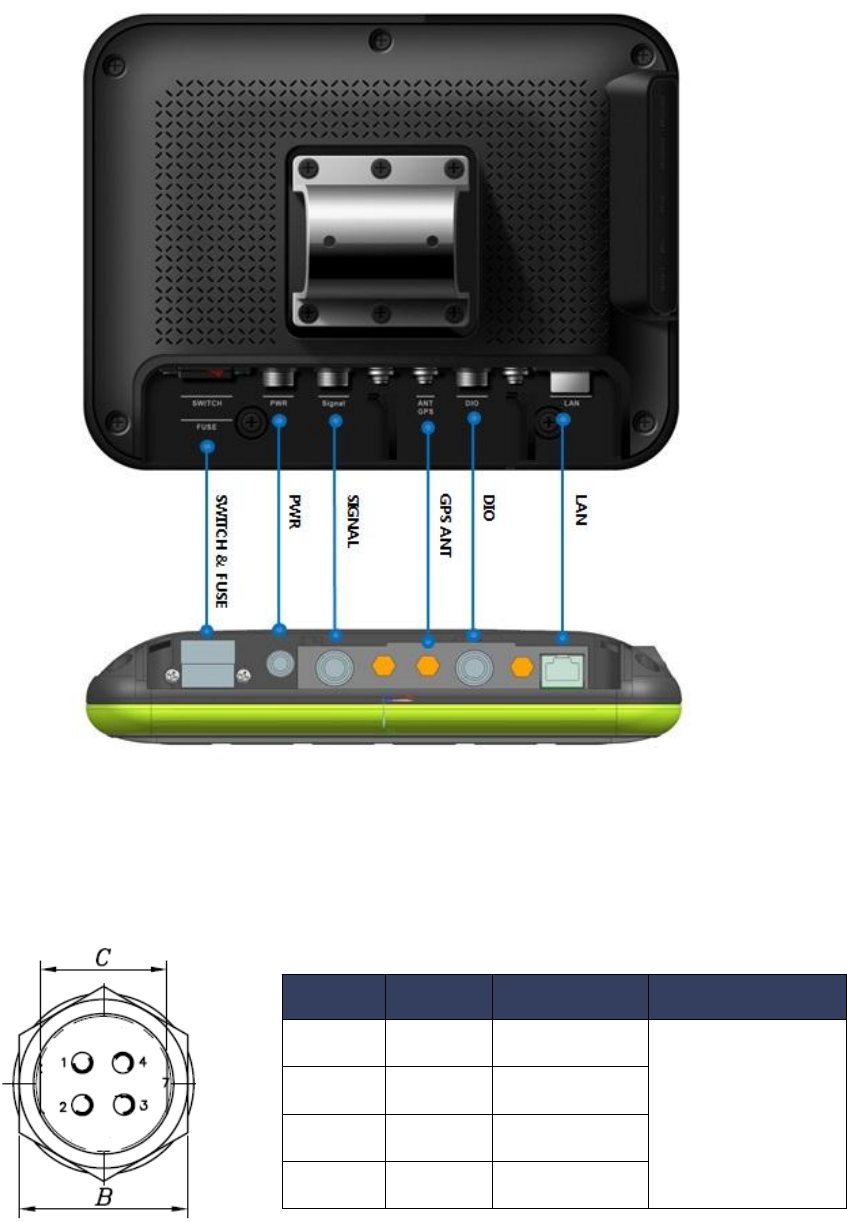
2.5 Connector and Power switch
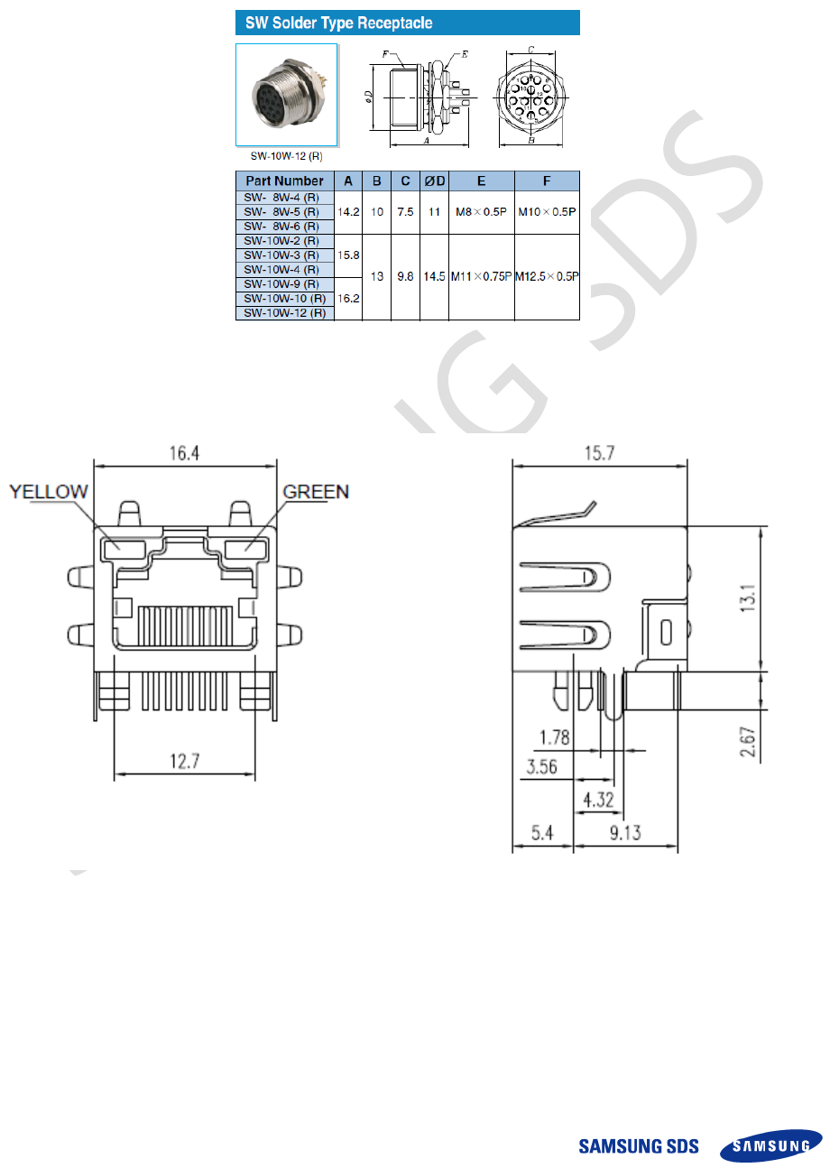
2.5.1 Signal & Power connector
2.5.2 LAN connector
System Manual – SAM-OCU-14 – 2013.12.05
Copyright ⓒ 2013 Samsung SDS Co., Ltd. All rights reserved | Confidential
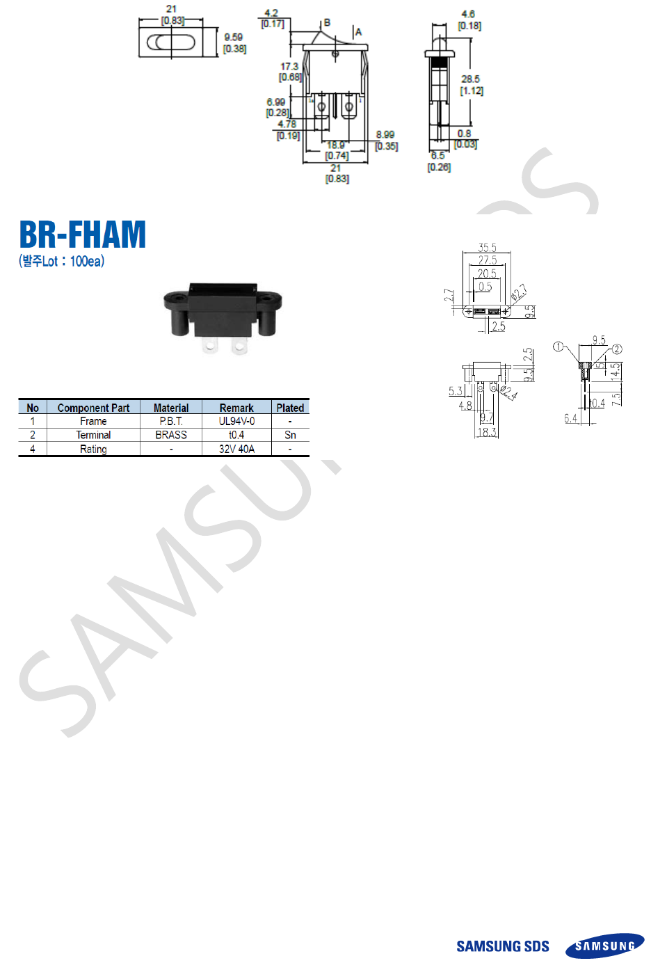
2.5.3 Power switch & Fuse holder
2.6 Connection Diagram
Figure 10 Connector Layout of Rear Cover
2.6.1 Rear Cover connector – PWR
Table 7 Specification of PWR Connector
Pin No
Name
Description
Connector Option
1
PWR
DC_IN
DC POWER IN
24V
2
PWR
DC_IN
3
GND
GND
4
GND
GND
System Manual – SAM-OCU-14 – 2013.12.05
Copyright ⓒ 2013 Samsung SDS Co., Ltd. All rights reserved | Confidential
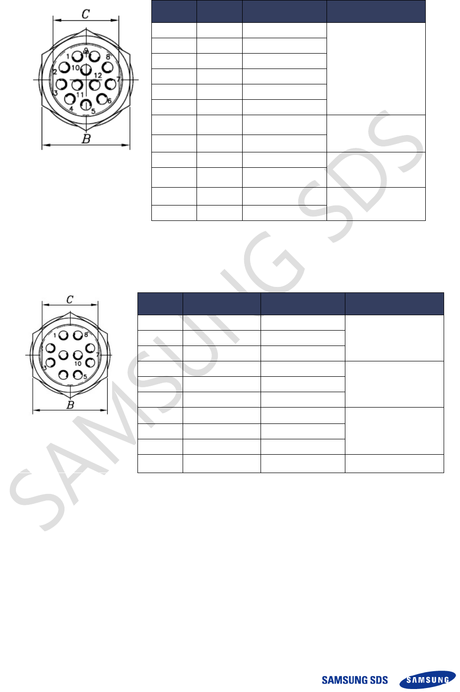
2.6.2 Rear Cover connector –SIGNAL
Pin No
Name
Description
Connector Option
1
VDD
DC_OUT 3.3V
RS232 Comm
2
RXD
Comm
3
TXD
Comm
4
GND
GND
5
RXD
Comm
6
TXD
Comm
7
RXD
RS232 & 485
RS232 or 485
(Optional)
8
TXD
RS232 & 485
9
485_A
Comm
RS485 Comm
10
485_B
Comm
11
CAN_H
Comm
CAN Comm
12
CAN_L
Comm
Table 8 Specification of SIGNAL Connector
2.6.3 Rear Cover connector –DIO
Pin No
Name
Description
Connector Option
1
VDD_EXT_DIO1
DC_OUT 3.3V
For GPIO 1
2
GPIO_IN1
GPIO INPUT
3
GPIO_OUT1
GPIO OUTPUT
4
VDD_EXT_DIO2
For GPIO 2
5
GPIO_IN2
GPIO INPUT
6
GPIO_OUT2
GPIO OUTPUT
7
VDD_EXT_DIO0
DC_OUT 3.3V
For GPIO 0
8
GPIO_IN0
GPIO INPUT
9
GPIO_OUT0
GPIO OUTPUT
10
GND
GND
Table 9 Specification of DIO Connector
System Manual – SAM-OCU-14 – 2013.12.05
Copyright ⓒ 2013 Samsung SDS Co., Ltd. All rights reserved | Confidential
2.7 Operation & Usage
1. Turn on the OCU, check the android OS booting by the LCD display. After boot-up, the
operator can use the OCU.
2. There are six (6) keys on front of OCU. The function for each key is as below;
- ROUTE: The selection of in-service route.
- START: The operator pushes this button when start the service.
- Payzone 1: The selection of fare payment type
- Payzone 2 : The selection of fare payment type
- Payzone 3 : The selection of fare payment type
- CANCEL: Cancelation of event.
3. The LCD display has a resistive touch panel for operator to operate the OCU by using his
finger.
4. There are USB port, Audio port and External Micro SD card slot on the right side of OCU.
5. There are Digital In/Output port, Serial communication port and LAN (Ethernet) port on the
rear cover of OCU. So, it supports variable interface.
6. The OCU has audio interface to support the announcement for operator.
his euipment complies ith radiation eposure limits set forth for an uncontrolled enironment
his euipment should be installed and operated ith minimum distance cm beteen the radiator your body
System Manual – SAM-OCU-14 – 2013.12.05
Copyright ⓒ 2013 Samsung SDS Co., Ltd. All rights reserved | Confidential
FCC STATEMENT
CAUTION: Changes or modifications not expressly approved by the party responsible for
compliance could void the user's authority to operate the equipment.
Note: This equipment has been tested and found to comply with the limits for a
Class A digital device, pursuant to part 15 of the FCC Rules. These limits are
designed to provide reasonable protection against harmful interference when
the equipment is operated in a commercial environment. This equipment
generates, uses, and can radiate radio frequency energy and, if not installed
and used in accordance with the instruction manual, may cause harmful
interference to radio communications. Operation of this equipment in a
residential area is likely to cause harmful interference in which case the user
will be required to correct the interference at his own expense.
Modifications not expressly approved by the manufacturer could void the user's
authority to operated the equipment under FCC rules.

System Manual – SAM-OCU-14 – 2013.12.05
Copyright ⓒ 2013 Samsung SDS Co., Ltd. All rights reserved | Confidential
Thank You.
Tel : +82-2-3429-2114
E-mail : sdspr@samsung.com
http : //www.sds.samsung.co.kr
Copyright ⓒ 2013 Samsung SDS Co., Ltd. All rights reserved | Confidential