Samsung SDS SMT-500P MiBUS OBE (BUS Management System) User Manual MiBUS OBE Manual
Samsung SDS Co., Ltd. MiBUS OBE (BUS Management System) MiBUS OBE Manual
User Manual
MiBUS OBE(SMT-500P)
USER MANUAL
User should uses in a distance over 20 cm
2
Copyright ⓒ 2013 Samsung SDS Co., LTD.
All rights reserved | Confidential
-1-
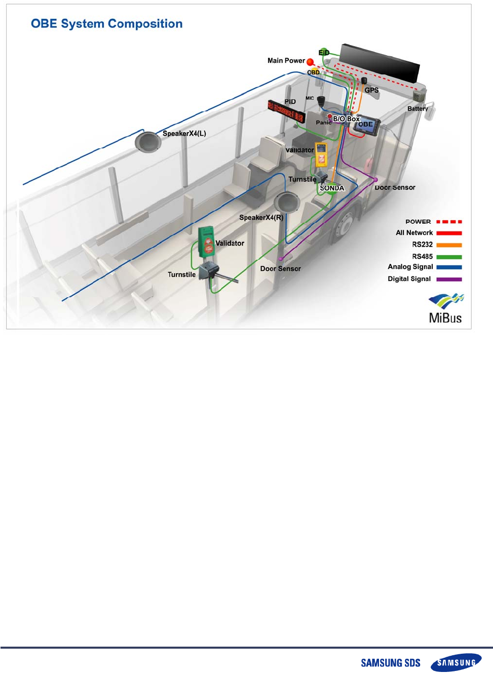
1. MiBUS OBE (BUS Management System C
omposition
Copyright ⓒ 2013 Samsung SDS Co., LTD.
All rights reserved | Confidential
-2-
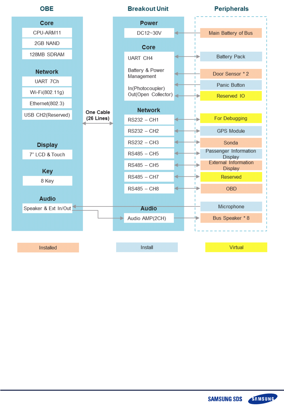
2. MiBUS OBE System Block Diagram
Copyright ⓒ 2013 Samsung SDS Co., LTD.
All rights reserved | Confidential
-3-
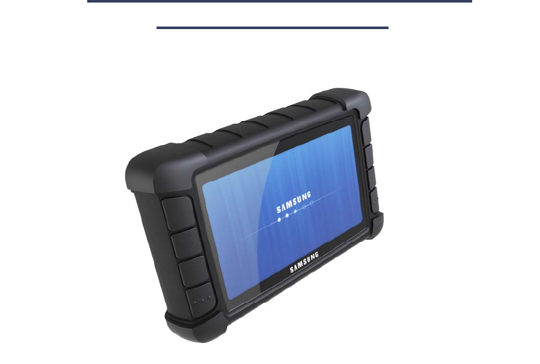
3. MiBUS OBE
A. OBE
OBE as the core device of the OBE system with 7-inch LCD with all of the inf
ormation collected and processed is a device that performs. OBE coordinates
of the GPS Module is based on the current location and status information of
the bus created, and also through various car devices and interfaces, the st
ate of the car (fuel state, RPM, etc.) and information (Turnstile, speed, cumul
ative distance, etc.) collect. In addition, the control center for voice communi
cation and Microphone, in the car to send to the emergency control center, p
erforms for the Panic Button and interface.
Information for passengers in the passenger terminal (PID) and external infor
mation terminal (EID) provides information on the text, the driver of the vehi
cle through a LCD monitor current service status (planned contrast variation,
the current stops, etc.) and provides various alarms and messages should.
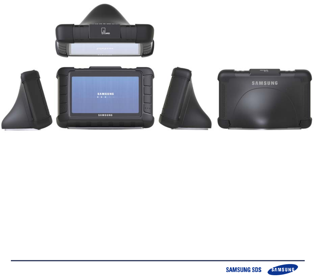
B. OBE Shape

Copyright ⓒ 2013 Samsung SDS Co., LTD.
All rights reserved | Confidential
-4-
C. Specification
Items Contents
CPU SAMSUNG S3C6410 ARM11/MAX 667MHz
Memory NAND Flash : 2GByte
SDRAM : 128MByte
OS Embedded Linux 2.6
Audio
AC 97 Audio CODEC, External 30W Audio AMP(Stereo), Internal
Speaker * 2
External Handy MIC
Display 7” LCD Touch Screen (4-wire) with outdoor brightness(400nits)
GPS Accuracy : 5 meters, Availability : 98%, 51 channel
Key 8 Keys: Left * 4, Right * 4
Network
J1939 * 1
UART * 7CH
USB * 2CH(MODEM)
10/100 Ethernet(IEEE802.3) * 1
Wi-Fi(IEEE802.11b,g)
Environment
condition
Temperature Operating Temperature: -5 ~ 85℃
Humidity Operating Humidity: 5% to 95%
Power Supply voltage range : DC 12 ~ 30V/Max 50W, External Battery
12V/4Ah
Size 232(W) * 145(H) * 56.5(D) mm
Copyright ⓒ 2013 Samsung SDS Co., LTD.
All rights reserved | Confidential
-5-
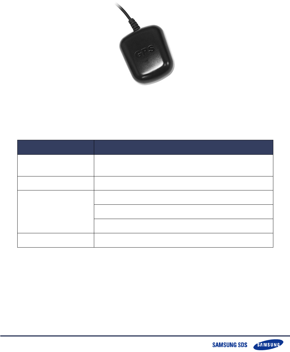
4. GPS Module
1. shape
.
Specification
Items Contents
CPU GPS DSP with integrated real time clock(RTC) ARM7EJ-S
CPU
Memory 4Mbit FLASH memory
Specifications
Built-in regulators (LDO)
GPS receiver With Patch Antenna
Patch Antenna Size : 25(W) * 25(H) * 4(D)mm
Size 48(W) * 57(H) * 15(D) mm
Copyright ⓒ 2013 Samsung SDS Co., LTD.
All rights reserved | Confidential
-6-
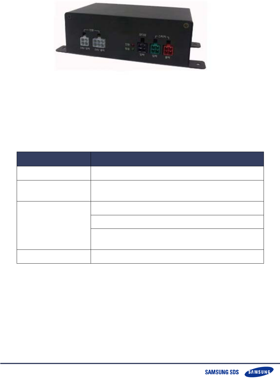
5.Breakout Box
1. Shape
1.1 Specification
Items Contents
CPU ST STM32F103 ARM Cortex-M3 72MHz
Memory Internal 256kByte FLASH
Internal 64Kbyte RAM
Specifications
Operating Temperature: -5 ~ 85℃
Operating Humidity: 5% to 95%
Supply voltage range : DC 12-30V/MAX 50W,
External Battery 12V
Size 155(W) * 80(H) * 40(D) mm

Copyright ⓒ 2013 Samsung SDS Co., LTD.
All rights reserved | Confidential
-7-
6. Warning
FCC RF INTERFERENCE STATEMENT
NOTE :
This equipment has been tested and found to comply with the limits for a Class B digital
device, pursuant to Part 15 of the FCC Rules. These limits are designed to provide
reasonable protection against harmful interference in a residential installation.
This equipment generates, uses and can radiate radio frequency energy and, if not
installed and used in accordance with the instructions, may cause harmful interference to
radio communications. However, there is no guarantee that interference will not occur in a
particular installation.
If this equipment does cause harmful interference to radio or television reception which
can be determined by turning the equipment off and on, the user is encouraged to try to
correct the interference by one or more of the following measures.
- Reorient or relocate the receiving antenna.
- Increase the separation between the equipment and receiver.
- Connect the equipment into an outlet on a circuit different from that to
which the receiver is connected.
- Consult the dealer or an experienced radio, TV technical for help.
- Only shielded interface cable should be used.
Finally, any changes or modifications to the equipment by the user not expressly
approved by the grantee or manufacturer could void the users authority to operate
such equipment

Copyright ⓒ 2013 Samsung SDS Co., LTD.
All rights reserved | Confidential
-8-
The user’s manual or instruction manual for an intentional or unintentional radiator shall
caution the user that changes or modifications not expressly approved by the party
responsible for compliance could void the user's authority to operate the equipment. In
cases where the manual is provided only in a form other than paper, such as on a
computer disk or over the Internet, the information required by this section may be
included in the manual in that alternative form, provided the user can reasonably be
expected to have the capability to access information in that form.
For a Class B digital device or peripheral, the instructions furnished the user shall include
the following or similar statement, placed in a prominent location in the text of the
manual:
NOTE: This equipment has been tested and found to comply with the limits for a Class B
digital device, pursuant to Part 15 of the FCC Rules. These limits are designed to provide
reasonable protection against harmful interference in a residential installation. This
equipment generates, uses and can radiate radio frequency energy and, if not installed
and used in accordance with the instructions, may cause harmful interference to radio
communications. However, there is no guarantee that interference will not occur in a
particular installation. If this equipment does cause harmful interference to radio or
television reception, which can be determined by turning the equipment off and on, the
user is encouraged to try to correct the interference by one or more of the following
measures:
-- Reorient or relocate the receiving antenna.
-- Increase the separation between the equipment and receiver.
-- Connect the equipment into an outlet on a circuit different from that to which the
receiver is connected.
-- Consult the dealer or an experienced radio/TV technician for help.