Samsung SDS SPS-700B Electric Payment System User Manual SPS 700B User Manual v2
Samsung SDS Co., Ltd. Electric Payment System SPS 700B User Manual v2
User Manual
SPS-700B
USER MANUAL
SPS-700B User Manual FCCID:P4YSPS-700B
Page: 2 / 11
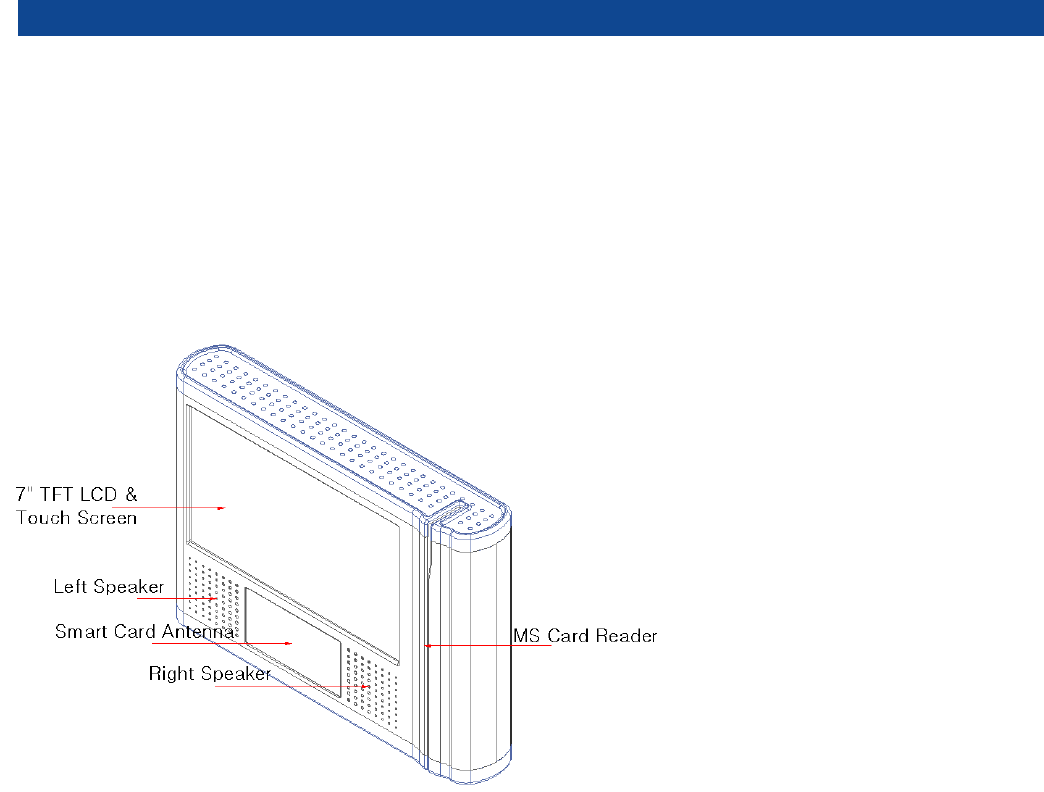
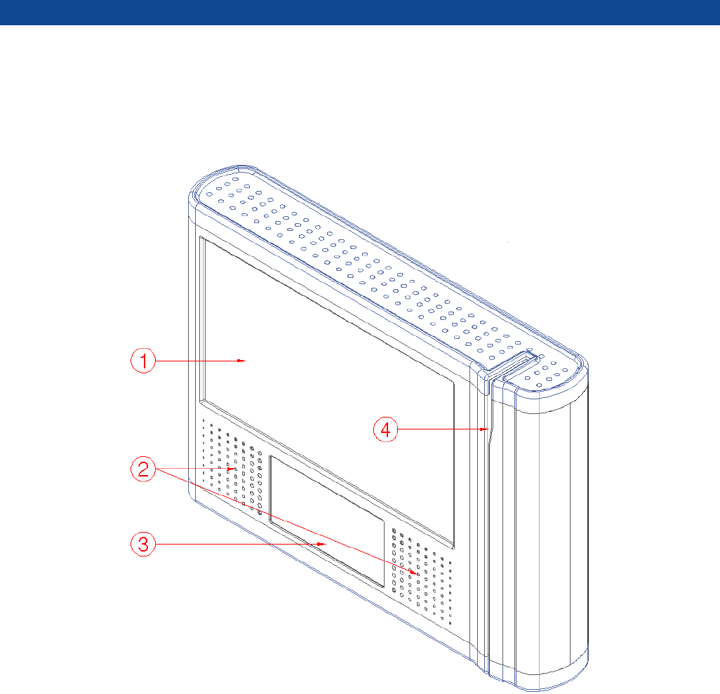
1 PIM CONSTRUCTION

SPS-700B User Manual FCCID:P4YSPS-700B
Page: 3 / 11
2 SPECIFICATIONS
Category Specifications
CPU SAMSUNG Arm11 667MHz
Memory
RAM SDRAM 128M Byte
NAND Flash 2G Byte
RTC Real Time Clock With Back-up Battery
DISPLAY 7" LCD Touch screen , 800 X 480 , 400Nits , Outdoor
RF & Smart CARD
Card Type MIFARE, ISO14443 A/B, (No support for Contact Smart Card)
Reading Distance Max 60mm
Security Algorithm Triple-DES
MS CARD MSR ISO TRACK 1,2 , Dual Head
SAM Slot SIMM Type 4 Slot
Video/Audio codec
Audio : Wolfson AC 97 Rev 2.2 Codec
Video : H.264 , H.263, MPEG4 SP, WMV9 ,VC1, GPU (built in)
Sound Speaker 8Ohm 2W X 2/Line Out Audio Jack
Interfaces
LAN 10/100 Base-T LAN
Wifi 802.11 b/g Wireless LAN
USB
Host 1.1 [2ch]
-. 1ch = Expansion( Included Breakout box )
RS232
5ch-5ports
-. 1port = GPS only
-. 1port = MDT only
-. 1port = Taxi Meter only
-. 2port = Expansion
SD Card Socket SDHC support (32G support)
GPS
Included ( The 51-channel,5 positioning engine boasts ), cable length :
2.5m
RFID RFID (13.56 MHz)
Bluetooth Bluetooth standard
O/S Embedded Linux 2.6.xx.x
Input Power DC 12 V
SPS-700B User Manual FCCID:P4YSPS-700B
Page: 4 / 11
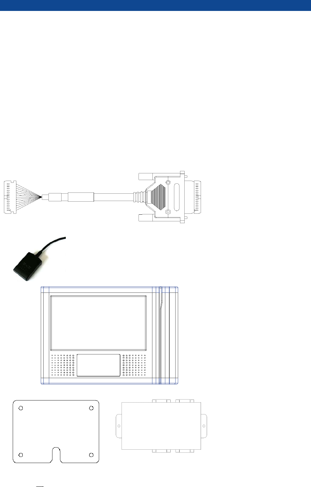
3 CONTENTS
Mounting Bracket
PIM
M5 x 10mm Set Bolt - 4EA
Breakout Box
Harness
GPS
Breakout Box
Mounting
k
PIM
GPS
Harness
SPS-700B User Manual FCCID:P4YSPS-700B
Page: 5 / 11
4 INSTALLATION
Product outline
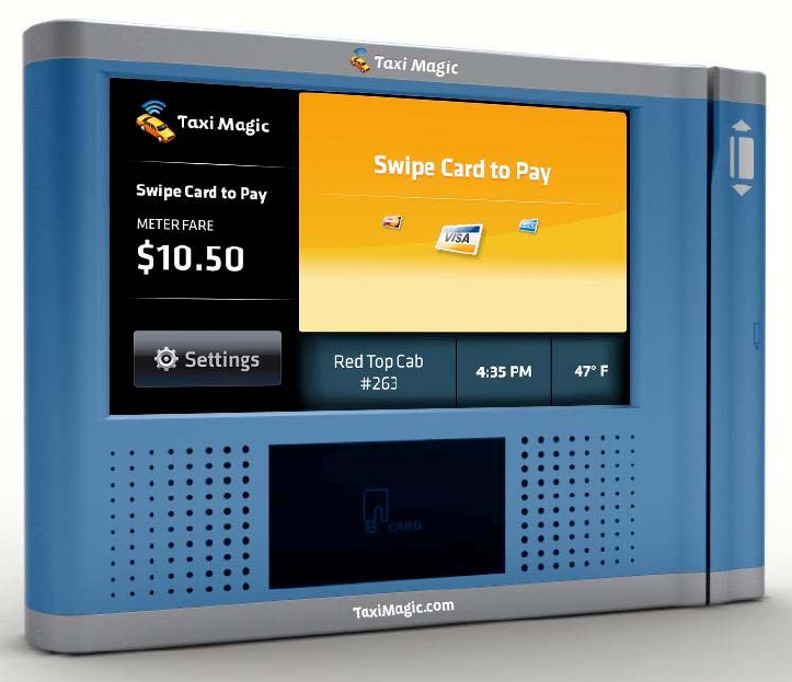
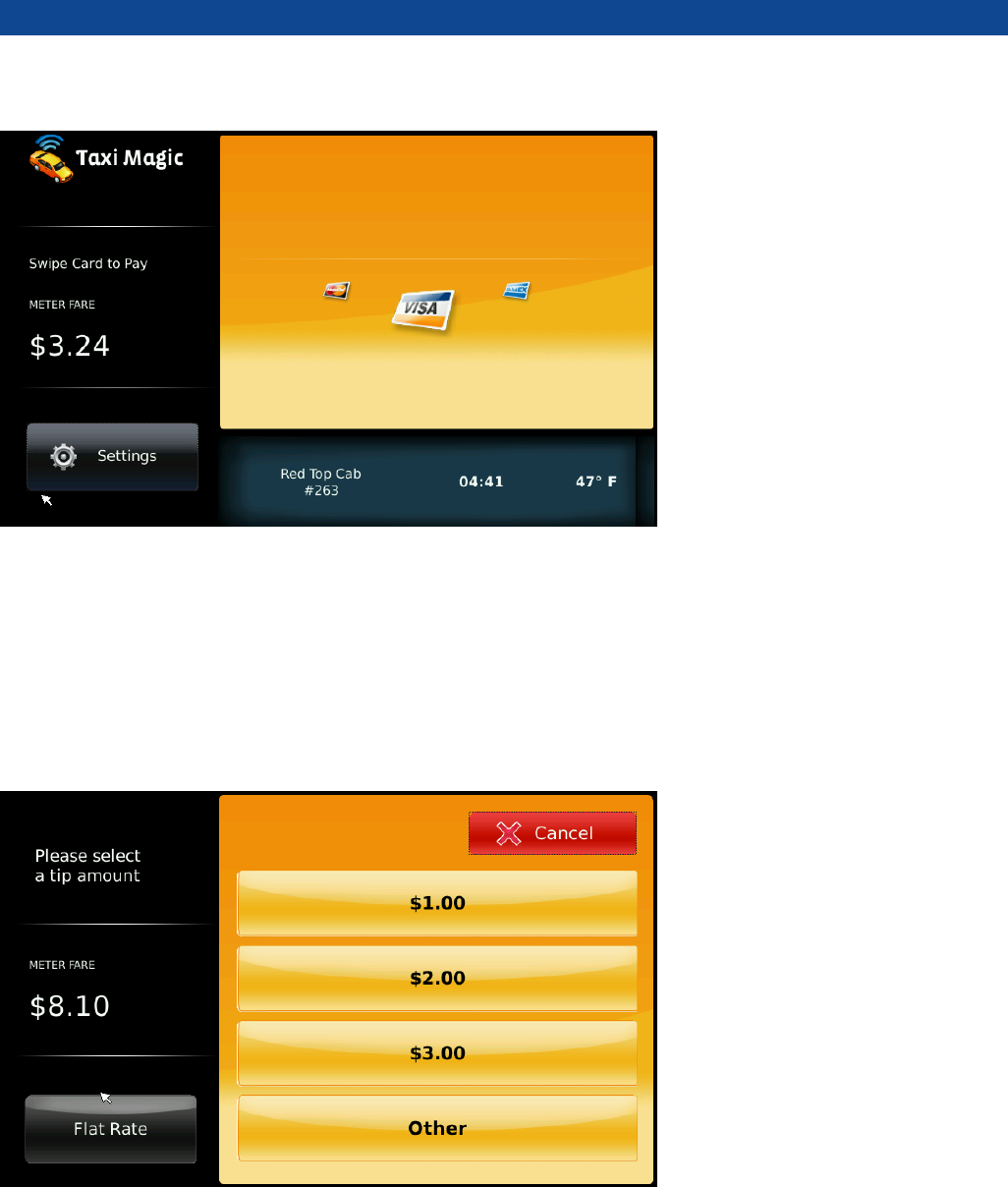
What is Taxi Magic?
Taxi magic is credit card reader and you may pay in a card by yourself after you arrive your destination.
[MAIN SCREEN]
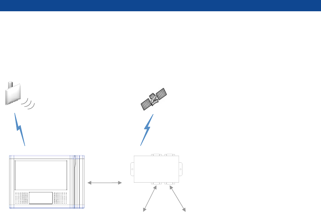
Wireless LAN GPS
Taxi Meter MDT
SPS-700B User Manual FCCID:P4YSPS-700B
Page: 6 / 11
As you can see above screen, you may see taxi fare on the left/ middle side on the screen. Also, you can
find time, temperature and the cab number on the bottom side.
And you can select tip amount on the [SETTINGS] menu.
[SETTINGS]
You may directly select the tip amount ($1, 2$, $3 or other) on the screen as showed on above screen and
there are also flat rate mode(10%, 15%, 20%) you may select at ease.
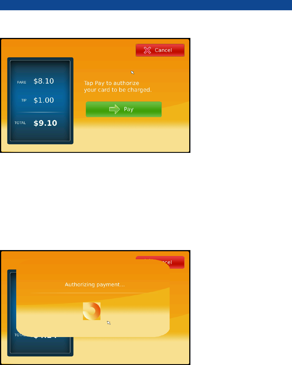
[TOTAL PAYMENT INFO]
SPS-700B User Manual FCCID:P4YSPS-700B
Page: 7 / 11
You can find total amount after choosing the tip as above. And you may continue the payment by pressing
[Pay] button if the total amount is correct. Or if the total amount is incorrect, you may return previous
screen by pressing CANCEL button.
[AUTHORIZING PAYMENT]
You will see the message “Please pass your card” after tapping the [Pay] button. Then, please pass your
card for authorizing payment.
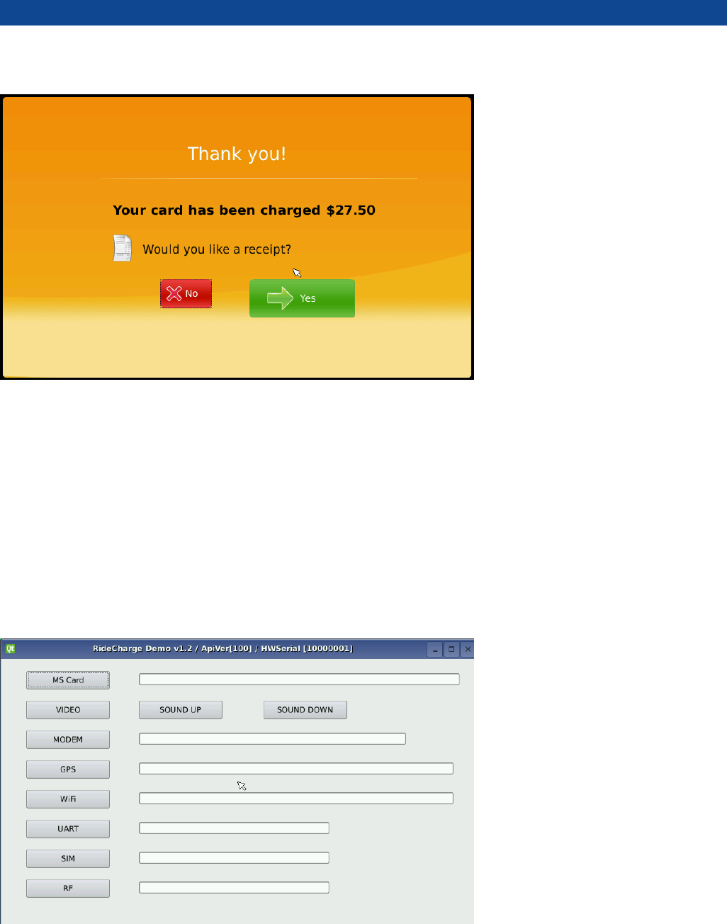
[RECEIPT PRINTOUT]
SPS-700B User Manual FCCID:P4YSPS-700B
Page: 8 / 11
After your card payment is done correctly, you may get a receipt by choosing “Yes” button on above
screen.
[HARDWARE SERIAL]
You can find each serial information of H/W part [as showed above]. Also, volume control is available.
SPS-700B User Manual FCCID:P4YSPS-700B
Page: 9 / 11
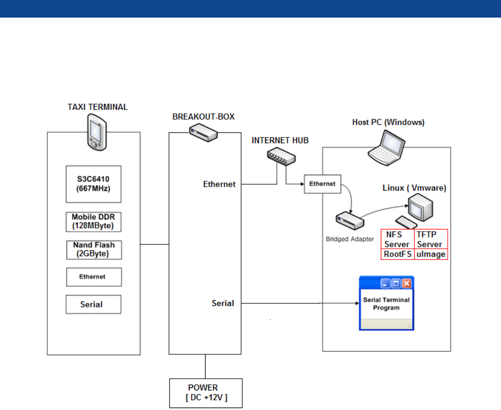
1. SYSTEM DEVELOPMENT CONECTION DIAGRAM
SPS-700B User Manual FCCID:P4YSPS-700B
Page: 10 / 11
TAXI TERMINAL
1 : TFTP LCD ( 800 X 480 )
2 : SPEAKER
3 : RF CARD ANTENNA
4 : MSR

SPS-700B User Manual FCCID:P4YSPS-700B
Page: 11 / 11
FCC RF INTERFERENCE STATEMENT
NOTE :
This equipment has been tested and found to comply with the limits for a Class B digital device,
pursuant to Part 15 of the FCC Rules. These limits are designed to provide reasonable protection
against harmful interference in a residential installation.
This equipment generates, uses and can radiate radio frequency energy and, if not installed and
used in accordance with the instructions, may cause harmful interference to radio
communications. However, there is no guarantee that interference will not occur in a particular
installation.
If this equipment does cause harmful interference to radio or television reception which can be
determined by turning the equipment off and on, the user is encouraged to try to correct the
interference by one or more of the following measures.
- Reorient or relocate the receiving antenna.
- Increase the separation between the equipment and receiver.
- Connect the equipment into an outlet on a circuit different from that to which the
receiver is connected.
- Consult the dealer or an experienced radio, TV technical for help.
- Only shielded interface cable should be used.
Finally, any changes or modifications to the equipment by the user not expressly
approved by the grantee or manufacturer could void the users authority to operate
such equipment