Samsung 400PX User Manual LCD MONITOR Manuals And Guides L0802463
SAMSUNG LCD Television Manual L0802463 SAMSUNG LCD Television Owner's Manual, SAMSUNG LCD Television installation guides
User Manual: Samsung 400PX 400PX SAMSUNG LCD MONITOR - Manuals and Guides View the owners manual for your SAMSUNG LCD MONITOR #400PX. Home:Electronics Parts:Samsung Parts:Samsung LCD MONITOR Manual
Open the PDF directly: View PDF ![]() .
.
Page Count: 178 [warning: Documents this large are best viewed by clicking the View PDF Link!]
SyncMaster 400PXn/4OOPX
/460PXn/460PX
Install Programs PDF Manuals _istration Safety instructions
introduction
Connections
Using the Software
Adjusting the LCD Display
Troubleshooting
Specifications
information
Appendix
© 2007 Samsung Electronics Co., Ltd All rights reserved
Select L_nguage Main Page
Safety Instructions
Notational
Power
installation
Clean
Others
#_t_oductior_
Conr_ectior_s
Uang the Software
Adjust ng the LCD Display
Troub eshooflr_ 9
Specificatior_a
#dormatior_
Appendix
SyncMaster
Mode_
The color end appearance of the product may vary depending on the model, and the product specifications are
subject to change without prior notice for reasons of performance enhancement.
Safety mnstructions
Notat ona
Please read the following safety instructions as they are designed to prevent damage to property and
harm to the user.
_ Warning /Caution
Failure to follow ddections noted by this symbol could result in bodily harm or damage to the
equipment
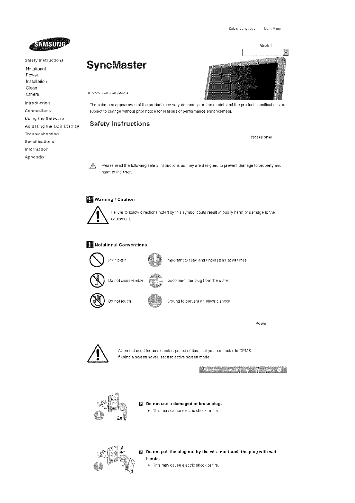
B Notational Conventions
Prohibited Impor[ant to read and understand at all times
Do not disassemble Disconnect the plug from the outlet
Do aottouch Ground to prevent an electric shock
Powe_
When not used for an extended period of time, set your computer to DPMS.
If using a screen saver, set it to active screen mode.
_'_
Do not use adamaged or loose plug.
® This may cause electric shock or fire
Do not pull the plug out by the wire nor touch the plug with wet
hands.
® This may cause electric shock or fire.
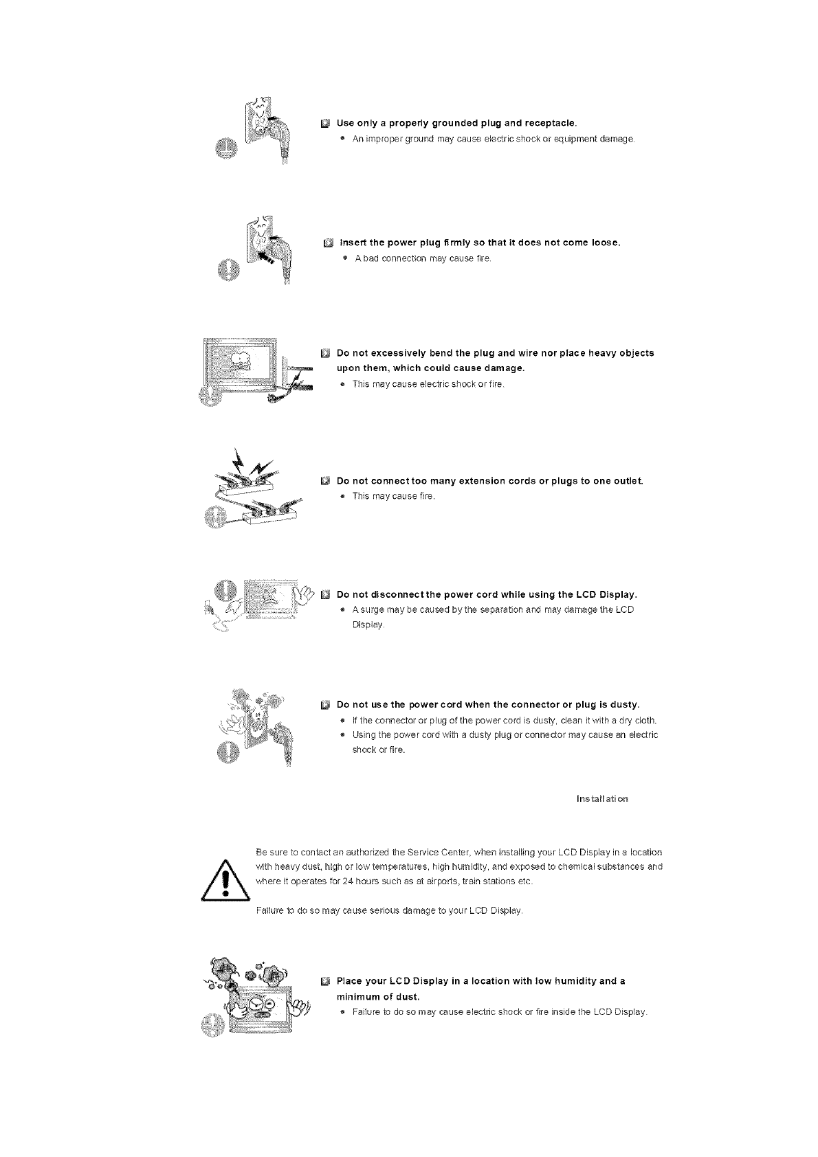
Use only aproperly grounded plug and receptacle.
® An improper ground may cause electricshockor equipment damage
Insert the power plug firmly so that it does not come loose.
Abad connection may cause fire
Do not excessively bend the plug and wire nor place heavy objects
upon them, which could cause damage.
® This maycause electricshockorfire
Do not connect too many extension cords or plugs to one outlet.
® This may cause fire.
Do not disconnect the power cord while using the LCD Display.
® A surge may be caused by the separation and may damage the LCD
Display
Do not use the power cord when the connector or plug is dusty.
® If the connector or plug of the power cord is dusty, clean it with a dry cloth
® Using the power cord with a dusb! plug or connector may cause an electric
shock or fire.
Ins tallation
Be sure to contact an authorized the Service Center, when installing your LCD Display in a location
with heavy dust, high or low temperatures, high humidity, and exposed to chemical substances and
where it operates for 24 hours such as at airports, train stations etc.
Failure to do so may cause serious damage to your LCD Display
Place your LCD Display in a location with low humidity and a
minimum of dust.
® Failure to do so may cause electric shock or fire inside the LCD Display
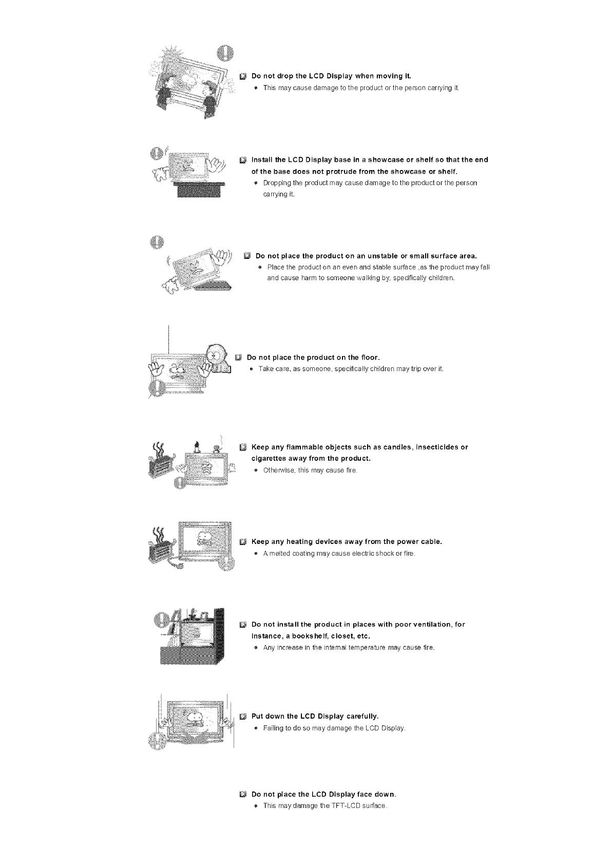
Donot drop the LCD Display when moving it.
® This may cause damage to the product or the person carrying it
Install the LCD Display base in ashowcase or shelf so that the end
of the base does not protrude from the showcase or shelf.
® Dropping the product may cause damage to the product or the person
carrying it
Do not place the product on an unstable or small surface area.
_, Placethe productonanevenandstablesurface,astheproductmayfall
and cause harm to someone walking by, specifically children.
Do not place the product on the floor.
Take care, as someone, specifically children may trip over it
Keep any flammable objects such as candles, insecticides or
cigarettes away from the product.
o Otherwise, this may cause the
Keep any heating devices away from the power cable.
® A melted coating may cause electric shock or fire
Do not install the product in places with poor ventilation, for
instance, a bookshelf, closet, etc.
® Any increase in the internal temperature may cause fire.
Put down the LCD Display carefully.
® Failing to do so may damage the LCD Display
Do not place the LCD Display face down.
® This may damage the TFT-LCD surface
The installation of the bracket must be done by aqualified
professional.
® Installing the bracket by unqualified personnel may result in injury.
® Always use the mounting device specified in the owner's manual
When installing the product, make sure to keep it away from the wall
(more than 10 cm /4 inches) for ventilation purposes.
® Poor ventilation may cause en increase in the internalternperatureofthe
p_oduct, resulting in a shortened component life and degraded
performance.
Keep the plastic packaging (bag) out of children's reach.
® The plastic packaging (beg) may cause suffocation if children play with it.
Clean
When cleaning the LCD Display case or the surface of the TFT-LCD screen, wipe with a slightly
moistened, sos fabric
Do not spray water or detergent directly onto the LCD Display.
® This rney cause damage, electric shock or fire.
Use the recommended detergent with a smooth cloth.
If the connector between the plug and the pin is dusty or dirty, clean
it properly using adry cloth.
® A dirty connector may cause electric shock or fire
Make sure to unplug the power cord before cleaning the product.
® Otherwise, this may cause electric shock or fire
Unplug the power cord from the power outlet and wipe the product
using asoft, dry cloth.
o Do not use any chemicals such as wax, benzene, alcohol, thinners,
insecticide, air freshener, lubricant or detergent.
Contact the SAMSUNG customer care center or Customer Center for
interior cleaning once ayear.
® Keep the product's interior clean. Dust which has accumulated in the
interior over an extended period of time may cause a malfunction or fire.
Others
Do not remove the cover (or back),
® This may cause electric shock or fire
® Refer to a qualified sen,icing company.
If your LCD Display does not operate normally - in particular, if there
is any unusual sound or smell coming from the LCD Display -
unplug it immediately and contact an authorized dealer or the
Service Center.
o This maycause electricshockorfire
Keep the product away from places exposed to oil, smoke or
moisture; do not install inside a vehicle.
® This may cause a malfunction, electric shock or fire.
®In particular, avoid operating the LCD Display near water or outdoors where
the LCD Display could be exposed to snow or rain
If the LCD Display is dropped or the casing is damaged, turn the
LCD Display off and unplug the power cord. Then contact the
Service Center.
® The LCD Display may malfunction, causing electric shock or _re
Disconnect the plug from the outlet during storms or lightning or if
it is not used for a long period of time.
® Failure to do so may cause electric shock or fire.
Do not try to move the LCD Display by pulling only the wire or the
signal cable.
® This may cause a breakdown, electric shock or fire due to damage to the
cable.
Do not move the LCD Display right or left by pulling only the wire or
the signal cable.
® This may cause a breakdown, electric shock or fire due to damage to the
cable.
Do not cover the vents on the LCD Display cabinet.
® Bad ventilation may cause a breakdown or fire
Do not place water containers, chemical products or small metal
objects on the LCD Display.
® This may cause a malfunction, electric shock or fire.
® If a foreign substance enters the LCD Display, unplug the power cord and
contact the Service Center
Keep the product away from combustible chemical sprays or
inflammable substances,
® This rnaycause an explosion or fire.
Never insert anything metallic into the LCD Display openings.
® This may cause electric shock, fire or injury
Do not insert metal objects such as chopsticks, wire and tools or
inflammable objects such as paper or matches into the vent,
headphone port or AV ports or etc.
® This may cause electric shock or fire. If an alien substances or water enters
the product, turn the product off. unplug the power connector from the wall
outletandcontacttheSeP_dceCenter
i!!__i_L_..! i !
_i/iii_i_!_ii!ii_i!ii_ii!!_i!!_!iiiii!i_i:_i_ iiii
When viewing a fixed screen for an extended period of time, residual
image or blurriness may appear.
® Change the mode to energy saving re,ode or set a screensaver to a
changing picture when away from the LCD Display for an extended period
o1time
Adjusts the resolution and frequency to the level appropriate for the
model.
® An inappropriate resolution may cause undesirable picture quality.
32 inch (80 cm) -1360 X 768
Viewing the LCD Display continuously at a too close angle may
result in damage to your eyesight.
To ease eye strain, take at least afive-minute break after every hour
of using the LCD Display.
Do not install the product on an unstable, uneven surface or a
location prone to vibrations.
® Dropping the productmaycausedamagetotheproductortheperson
carrying it. Using the product in a location prone to vibrations may shorten
the lifetime of the product or may cause the product to catch fire
When moving the LCD Display, turn off and unplug the power cord.
Make sure that all cables, including the antenna cable and cables
connected to other devices, are disconnected before moving the
LCD Display.
® Failure to disconnect cables may damage it and cause fire or electric
shock.
Make sure there are more than two people when moving the
product.
® Droppingti_e productmay caasea malfunction or injury to the person
carrying it.
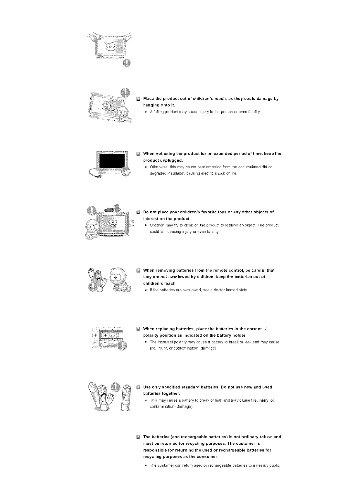
Place the product out of children's reach, as they could damage by
hanging onto it.
® A falling product may cause injury to tile person or even fatality.
When not using the product for an extended period of time, keep the
product unplugged.
® Otherwise, this may cause heat emission from the accumulated dirt or
degraded insulation, causing electric shock or fire
Do not place your children's favorite toys or any other objects of
interest on the product.
® Children may try to climb on lile product to retrieve an object. The product
could fall, causing injury or even fatality
When removing batteries from the remote control, be careful that
they are not swallowed by children, keep the batteries out of
children's reach.
®If the batteries are swallowed, see a doctor immediately
When replacing batteries, place the batteries in the correct +/-
polarity position as indicated on the battery holder.
® The incorrect polarity may cause a battery to break or leak and may cause
lira. injury> or contaminalion (damage)
Use only specified standard batteries. Do not use new and used
batteries together.
® This may cause a battery to break or leak and may cause fire, injury, or
contamination (damage).
The batteries (and rechargeabte batteries) is not ordinary refuse and
must be returned for recycling purposes. The customer is
responsible for returning the used or rechargeable batteries for
recycling purposes as the consumer.
® The customer can return used or rechargeable batteries to a nearby public

recyclingcenterortoastoresellingthesametypeofthebatteryor
rechargeablebattery.
© 1995~2007 SAMSUNG ALL Rights Reserved
SyncMaster 400PXn/460PXn
Select L.ang_age Man Page
Safety _r_struct on£
I}troduct on
Package Contents
Your LCD Display
Machanical Layout
Co_'l#ect_oRs
bsng the Software
Adjusting the LCD Disp ay
Troubleshooting
Spec fieat ons
_Morma_: ot_
SyncMaster
/V_odeB
The cobr and appearance of the product may vary depending on the model and the product specifications are
subject to change without prior notice for reasons of performance enhancement.
introduction
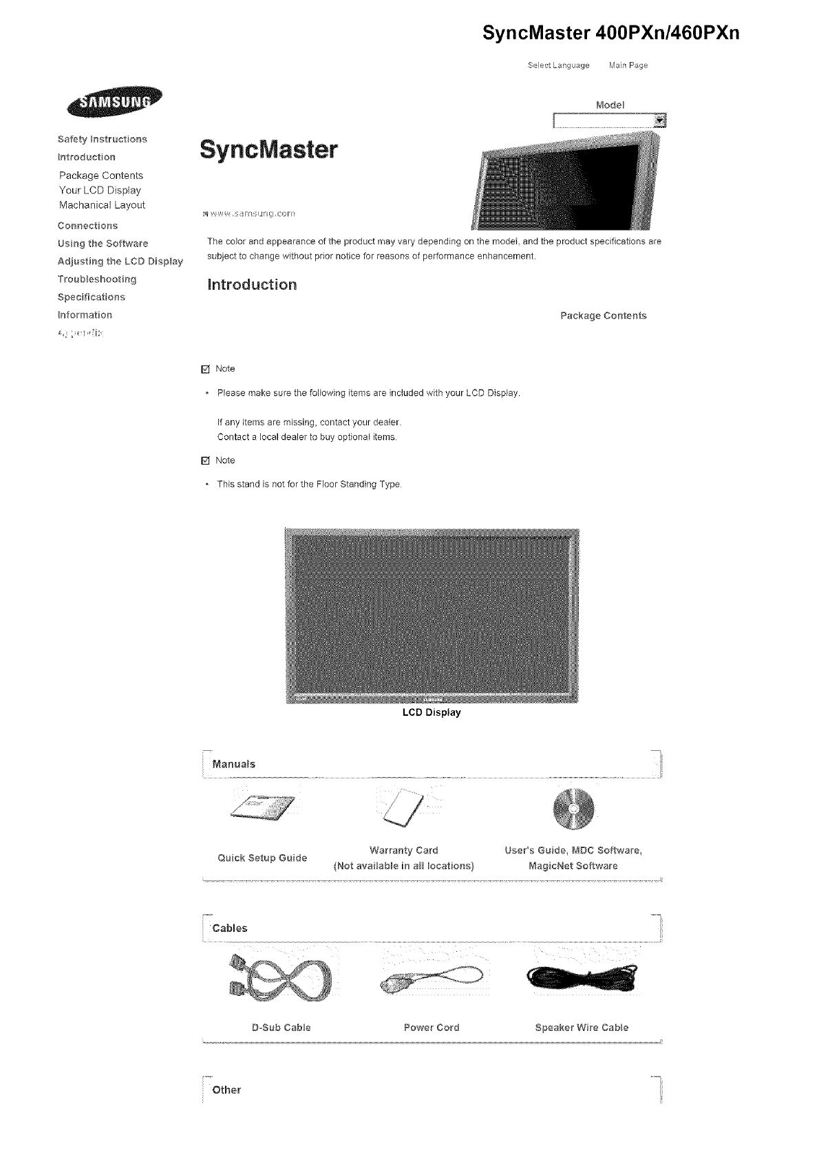
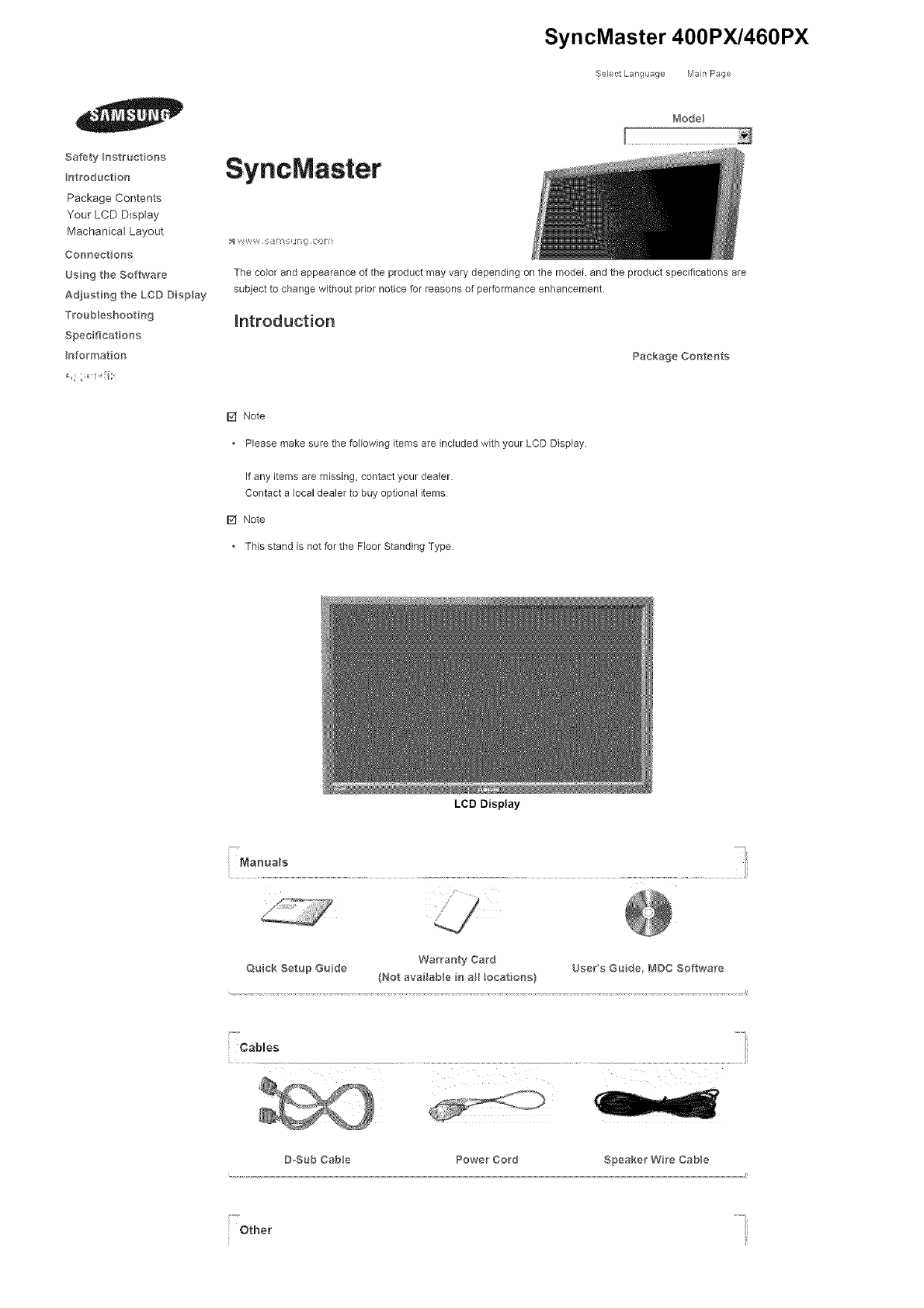
Package Contents
[] Note
• Please make sure the following items are included with your LCD Display.
If any items are missing, contact your dealer.
Contact a local dealer to buy optional items
[] Note
• This stand is not for the Floor Standing Type
LCD Display
Manua s -i
1
Quick Setup Guide Warranty Card UsePs Guide, fV_DC Software,
(Not availabBe in al_ Bocations) Mag cNet Software
Cables
D=Sub Cable Power Cord Speaker Wire CaMe
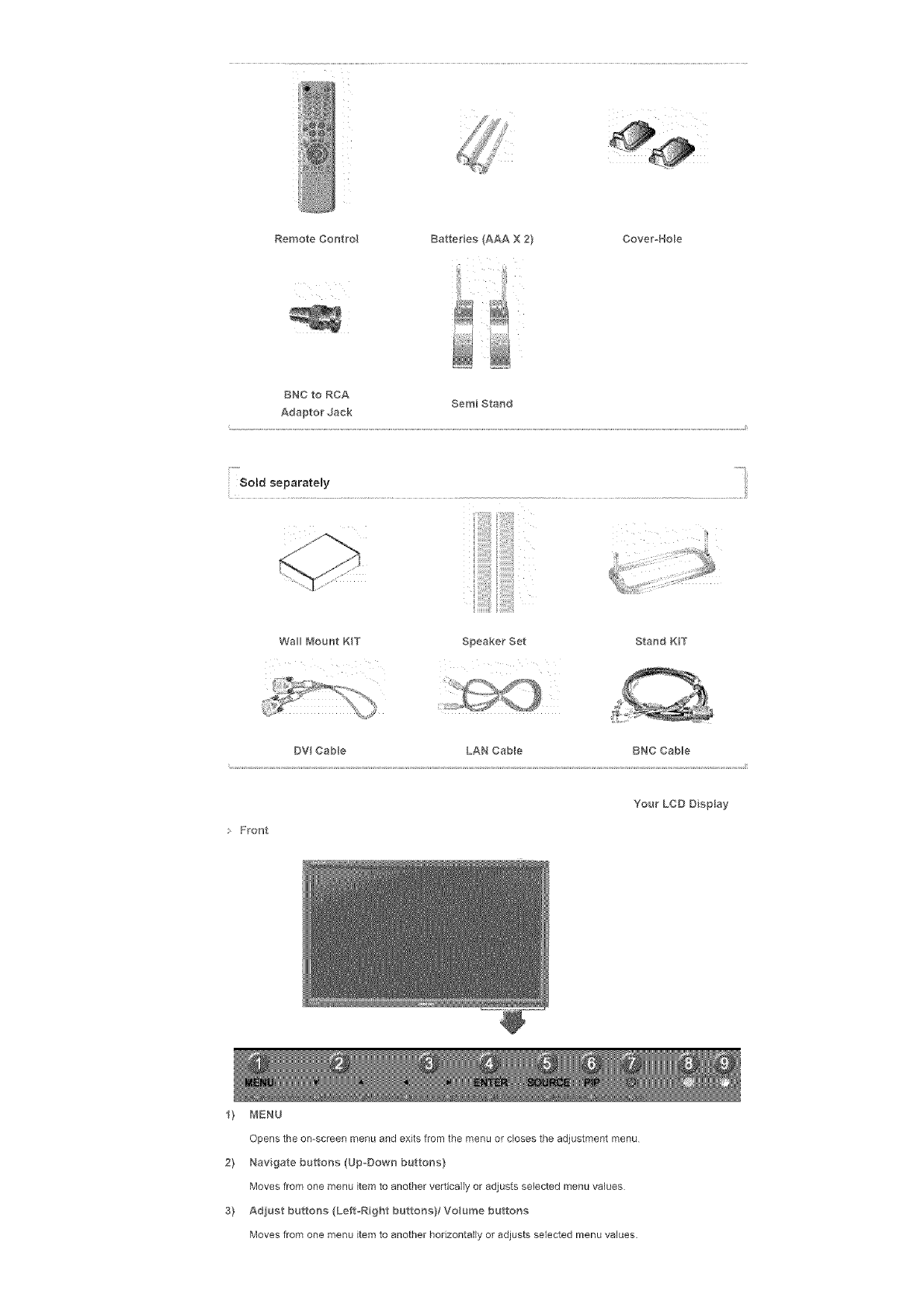
Other
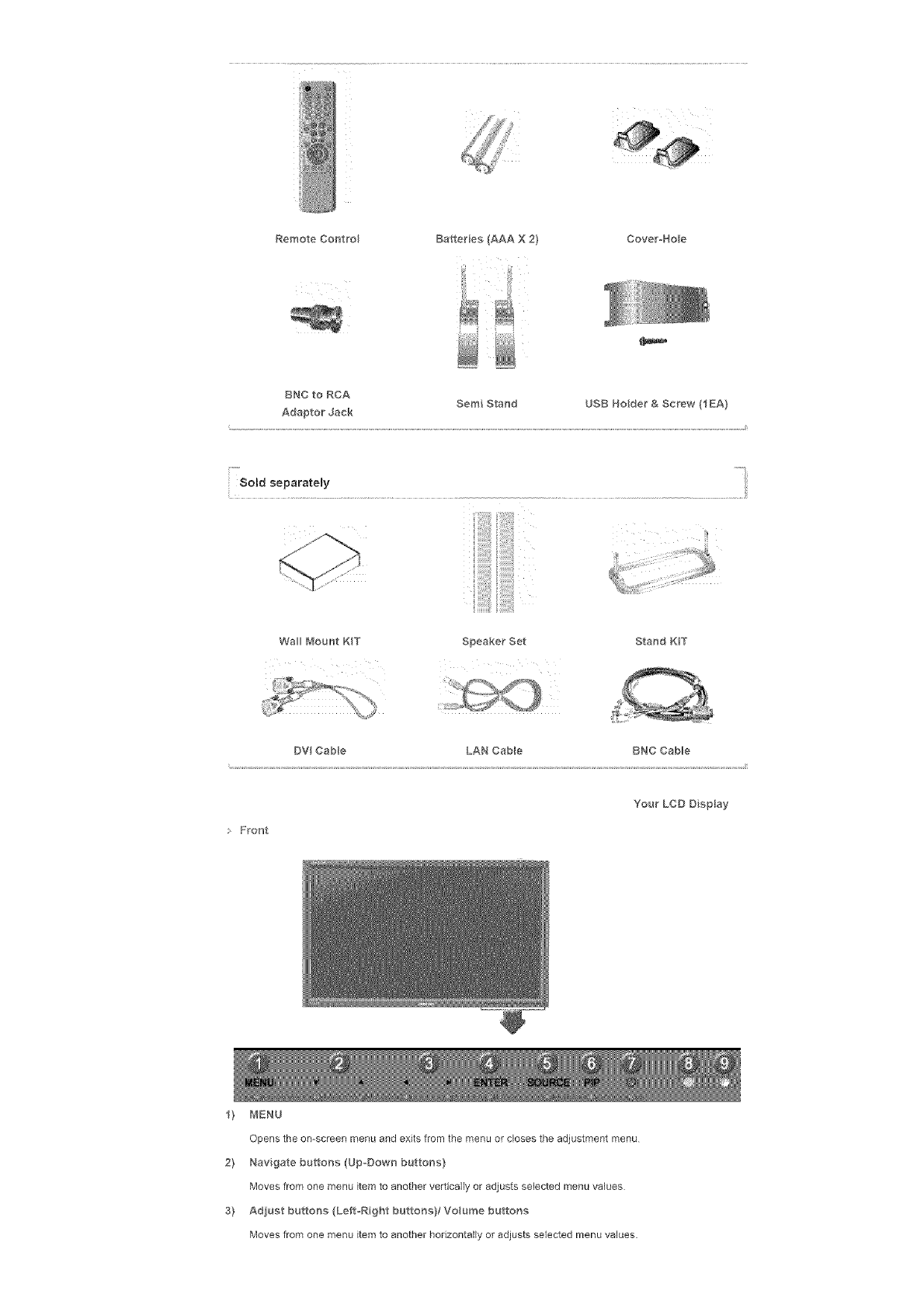
RemoteControl Batteries(AAAX2} Cover_Hole
BNCtoRCA SemiStand USBHolder&Screw(IEA}
AdaptorJack
i -m
Sold separatemy
Wal_ Mount KIT Speaker Set Stand K_T
DV Cable LAN CaMe BNC Cable
• Front
Your LCD Display
_) MENU
Opens the on-screen menu and exits from the menu or closes the adjustment menu
2} Navigate buttons (Up-Down buttons)
Moves from one menu item to another vertically or adjusts selected menu values
3) Adjust buttons (Left-Right buttons}/Voume buttons
Moves from one menu item to another horizontally or adjusts selected menu values.
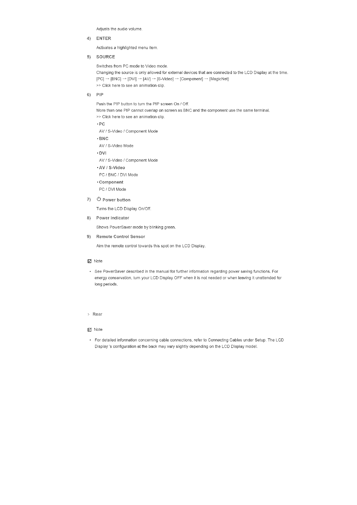
Adjuststheaudiovolume
4} ENTER
Activatesahighlightedmenuitem
5'} SOURCE
SwitchesfromPCmodetoVideomode
ChangingthesourceisonlyallowedforexternaldevicesthatareconnectedtotheLCDDisplayatthetime.
[PC]_ [BNC]_[DVl]_ [AV]_ IS-Video]_[Component]_ [MegicNet]
>>Clickheretoseeananimationclip.
6'} PP
Push the PIP button to turn the PIP screen On /Off
More than one PIP cannot overlap on screen as BNC end the component use the same terminal.
>> Click here to see an animafion clip
• PC
AV /S-Video /Component Mode
.BNC
AV /S-Video Mode
• DV
AV /S-Video /Component Mode
• AV /S-Video
PC /BNC /DVI Mode
•Compor_er_t
PC /DVl Mode
7'} O Powe_ button
Turns the LCD Display On/Off
8'} Powe_ indicato_
Shows PowerSaver mode by blinking green.
9'} Remote Control Senso_
Aim the remote control towards this spot on the LCD Display.
[] Note
See PowerSaver described in the manual for further informafion regarding power saving functions. For
energy conservation, turn your LCD Display OFF when it is not needed or when leaving it unattended for
long periods.
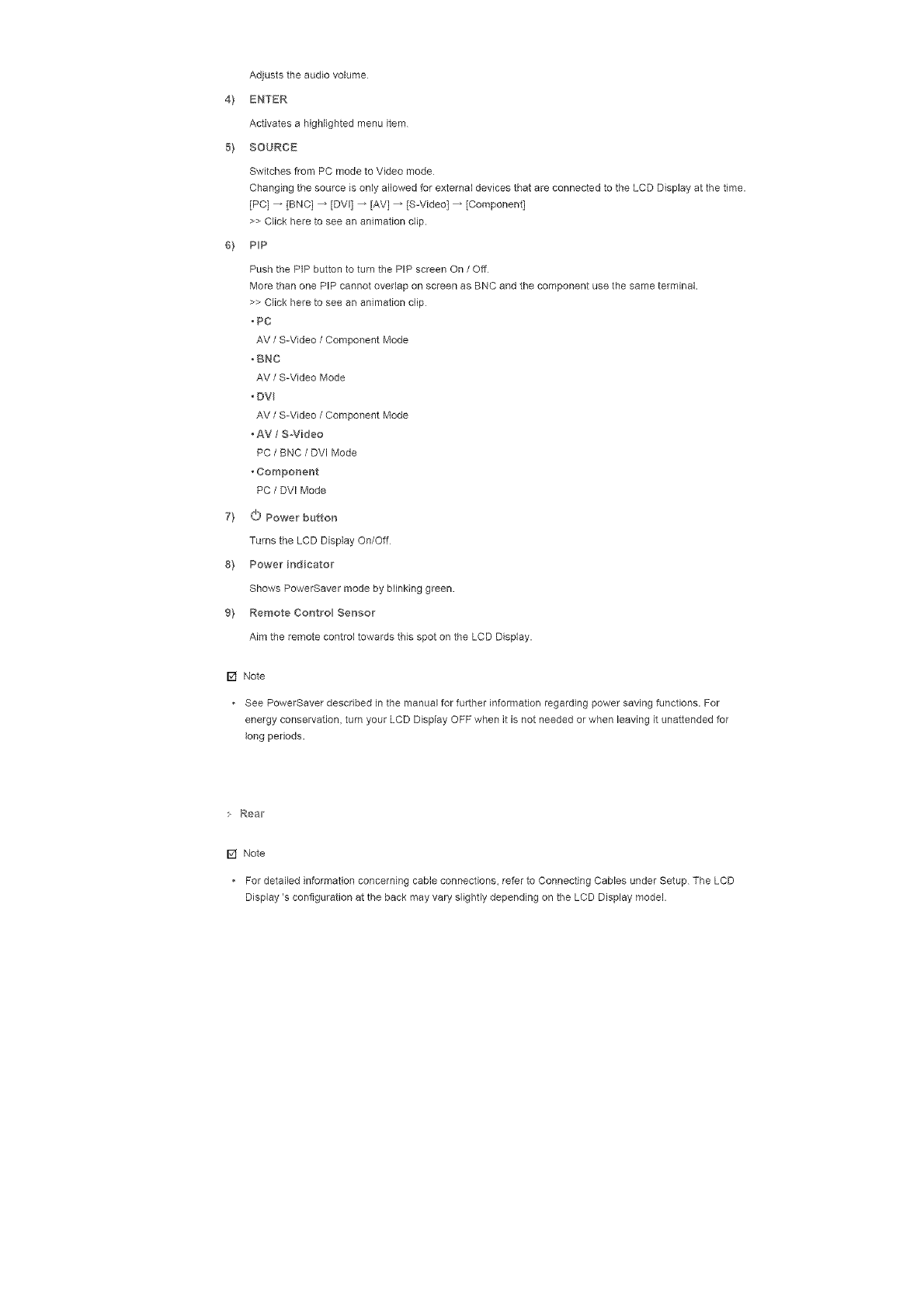
Real['
[] Note
• For detailed information concerning cable connections, refer to Connecting Cables under Setup The LCD
Display's configuration at the back may vary slightly depending on the LCD Display model.

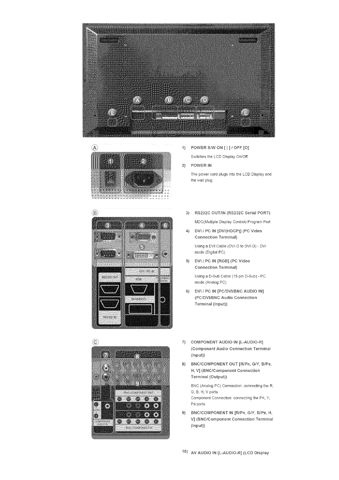
1} POWERS/WON[ I ] ; OFF[O]
Switches the LCD Display On/Off
2} POWER IN
The power cord plugs into the LCD Display and
the wall plug
3} RS232C OUT/BN (RS232C SeNaB PORT}
MDC(Multiple Display Control) Program Port
4} DV fPC N[DV(NDCP}](PCVdeo
Connection Te_minaB}
Using a DVl Cable (DVFD to DVI-D) - DVI
mode (Digital PC)
5} DVl /PC IN [RGB] (PC Video
Connection Termir_a_}
Using a D-Sub Cable (15 pin D-Sub) - PC
mode (Analog PC)
6} DV fPC N [PC/DV/BNC AUDBO N]
(PC/DV_IBNC Audio Connection
TerminaB (_nput}}
7} COMPONENT AUDBO N [LoAUD_O-R]
(Component Audio Connection Termir_a
( nput}}
8} BNC/COMPONENT OUT [R/PR, G/Y, B/P8
H, V] (BNC/Compor_er_t Cor_r_ection
TerminaB (Output}}
BNC (Analog PC) Connection: connecting the R,
G, B, H, V ports
Component Connection: connecting the PR, Y,
PB ports
9} BNC/COMPONENT IN [R/PR, G/Y, BIPB, H,
V] (BNC/Component Connect on Termina_
input}}
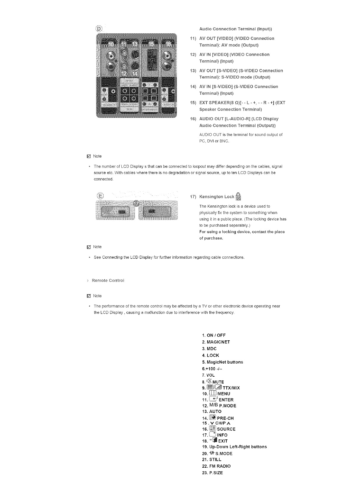
10) AV AUDIO N [L-AUD O_R] (LCD Display
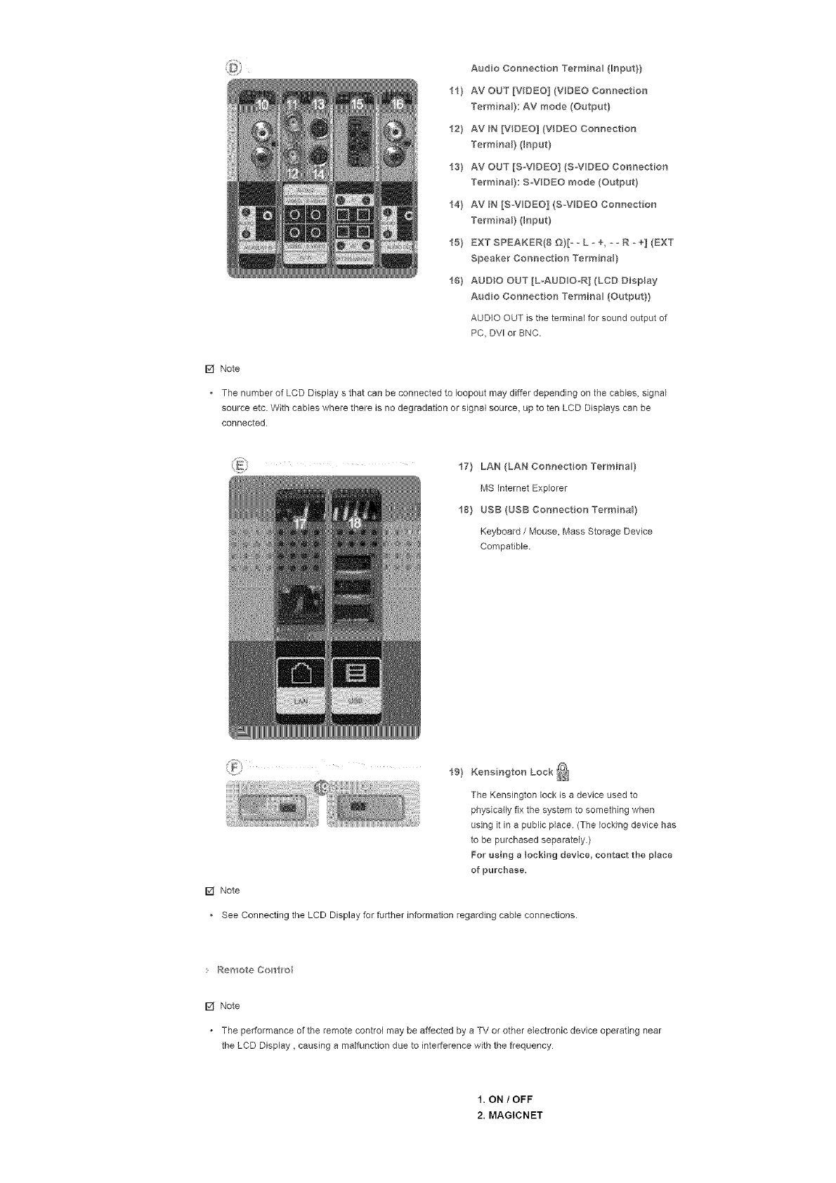
AudioConnectionTermna_(Bnput}}
11}AVOUT[VIDEO](VDEOConnection
TerminaB}:AVmode(Output}
12}AVIN[VIDEO](VIDEOConnection
TerminaB}(_np_t}
13}AVOUT[S-V_D£O](S_VOEOConnection
TerminaB}:S-VIDEOmode(Output}
14}AVIN[S_VDEO](S_VDEOConnection
TerminaB}(Input}
15}EXTSPEAKER{8E)}[- _L -+, _ oR _ +] (EXT
Speaker Connection TerminaB)
16} AUDIO OUT [L-AUDiO-R] {LCD Display
Audio Connection Termina_ (Output})
AUDIO OUT is the terminal for sound output of
PC, DV[ or BNC.
F2f Note
• The number of LCD Display s that can be connected to Ioopout may differ depending on the cables, signal
source etc With cables where there is no degradation or signal source, up to ten LCD Displays can be
connected.
I7} LAN (LAN Connection Termina }
MS [nternet Explorer
I8} USB (USB Connection TerminaB)
Keyboard /Mouse, Mass Storage Device
Compatible.
19} Kensington Lock _
The Kensingtonlockisa deviceused to
physically fix the system to something when
using it in a public place. (The locking device has
to be purchased separately.)
For using a locking device, contact the peace
of purchase.
[] Note
See Connecting the LCD Display for further information regarding cable connections.
Remote Contwo_
[] Note
. The performance of the remote control may be affected by a TV or other electronic device operating near
the LCD Display, causing a malfunction due to interference with the frequency
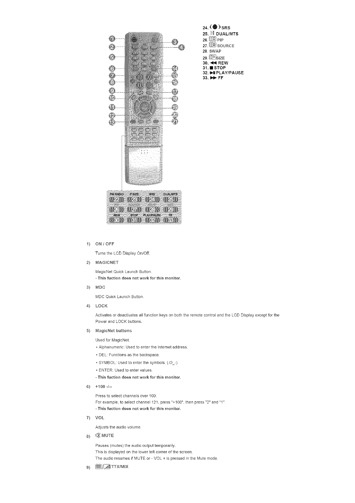
1, ON /OFF
2. MAGICNET
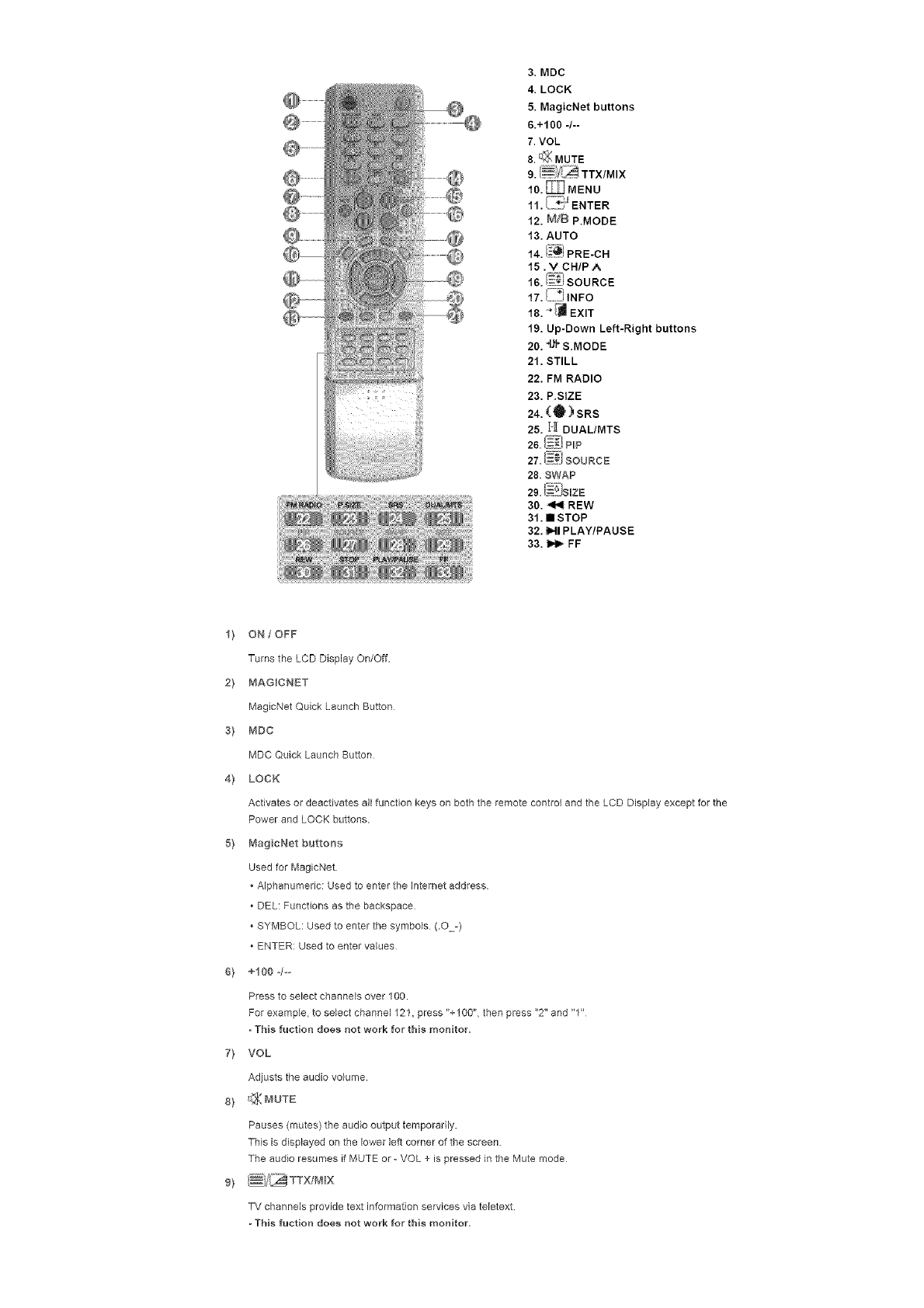
3. MDC
4. LOCK
5. MagicNet buttons
6.+100 -/--
7. VOL
8. _;_ MUTE
10. _MENU
7
11. ENTER
12. M/B P.MODE
13. AUTO
14. (_I PRE-CH
15 . V CHIP A
16. !_}} SOURCE
17. _i INFO
18. _ EXIT
19. Up-Down Left-Right buttons
20.4_'F S.MODE
21. STILL
22. FM RADIO
23. P.StZE
24. (Q_) SRS
25. H DUAL/MTS
26. _i PLP
27. =..:_SOURCE
28. SWAP
29. (__JSIZE
30. _ REW
31. • STOP
32. HI PLAY/PAUSE
33. _ FF
1} ON /OFF
Turns the LCD Display On/Off.
2} MAGICNET
MagicNet Quick Launch Button
s} MDC
MDC Quick Launch Button
4} LOCK
Activates or deactivates all function keys on both the remote control and the LCD Display except for the
Power and LOCK buttons.
5} MagcNet buttons
Used for MagicNet
* Alphanumeric: Used to enter the Internet address.
* DEL: Functions as the backspace
* SYMBOL: Used to enter the symbols (.O-)
* ENTER: Used to enter values
6} +100 4--
Press to select channels over 100.
For example, to select channel 121, press %100", then press "2" and "1"
- This ruction does not work for this monitor,
7} VOL
Adjusts the audio volume.
8} _ MUTE
Pauses (mutes) the audio output temporarily,
This is displayed on the lower left corner of the screen
The audio resumes if MUTE or -VOL + is pressed in the Mute mode
9) /_i/_}_ TTX/M_X
TV channels provide text information services via tebtext.
-This fuction does not work for this monitor,
10}_mEnu
Opens the on-screen menu and exits from the menu screen or closes the screen adjustment menu.
ii} {_!:_ ENTER
Activates a Mghlighted menu item
12) M_B P.MODE
When you press this button, current picture mode is displayed on the lower center of the screen
AV tS-Video /Component : P.MODE
The Monitor has four automatic picture settings that are preset at the factory
Then push button again to circle through evailabb preconfigured modes.
( Dynamic _ Standard _ Movie _ Custom )
PCtDVI/BNC : M/B (MagicBright)
MagicBdght TM is a new feature providing the optimum viewing environment depending on the contents of
the image you are watching
Then push button again to circle through evailabb preconfigured modes.
(Entertain _ Internet _ Text _ Custom )
13) AUTO
Adjuststhescreen displayautomaticallyinPC mode
By changingthe resolutioninthecontrolpanel,autofunctionisperformed,
14) ii_°_ PREoCH
Returns to the immediately previous channel
This fuction does not work for this monitor,
15) vCHIP A
In TV mode, selects TV channels
-This fuction does not work for this monitor,
i_ i_ SOURCE
Changes thevideo source
i7} (]_#I BNFO
The currentpictureinformationisdisplayedinthe topleftcornerofthe screen
is_ - [J emT
Exits from the menu screen
19} Up@own Left*Right buttons
Moves from one menu item to another horizontally, vertically or adjusts selected menu values
20) 4)1"S,MODE
When pressing this button, the current mode is displayed at the bottom centre of the screen.
The LCD Display has a built-in high fidelity stereo amplifier
Then press the button again to circle through available preconfigured modes
( Standard _ Music _ Movie _ Speech _ Custom )
2I) STILL
Press the button once to freeze the screen Press it again to unfreeze
22} FM RADIO
Turns the FM Radio on/off
in PC/DVI mode, sets the SOUND to FM Radio.
In general Video mode, selects FM Radio, end turns off the screen
In areas where the signal is weak, noise may occur during FM radio broadcasts.
- This ruction does not work for this monitor,
23} P,S_ZE
Press to change the screen size.
24} ('l_) SRS
SRS
25) _ T_[ DUAL/MTS
DUAL-
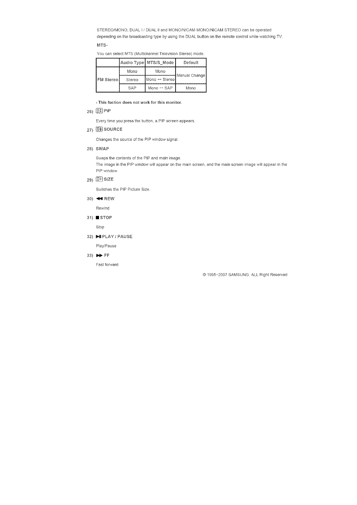
STEREO/MONO, DUAL I /DUAL II and MONO/NiCAM MONO/NICAM STEREO can be operated
depending on the broadcasting type by using the DUAL button on the remote control while watching TV
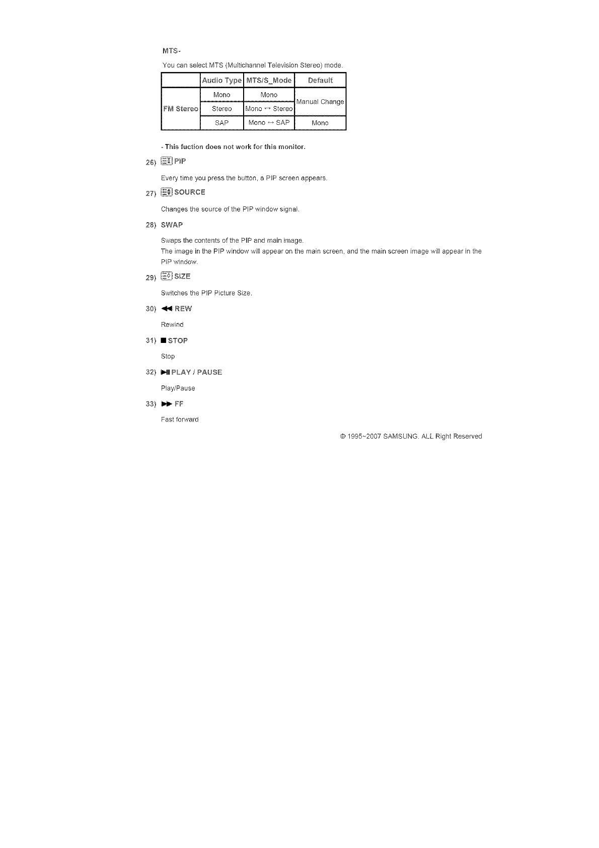
MTS,-
You can select MTS (Multichannel Television Stereo) mode.
Audio Type MTS/S Mode DefauBt
Mono Mono
Manual Change
FM Stereo Stereo Viono _ Stereo
SAP Mono _ SAP Mono
-This fuction does not work for this monitor.
26) i_i PIP
Every time you press the button, a PIP screen appears
I_._ SOURCE
27} _:=
Changes the source of the PIP window signal
28) SWAP
Swaps the contents of the PIP and main image
The image in the PIP window will appear on the main screen, and the main screen image will appear in the
PiP window
29) ,_l S_ZE
Switches the PIP Picture Size.
30} _ REW
Rewind
31) • STOP
Stop
32) I_1 PLAY / PAUSE
Play/Pause
33) _ EF
Fast forward
© 1995-_2007 SAMSUNG ALL Right Reserved
SyncMaster 400PX/460PX
Select Lang _age Man Page
Safety _nstruct ons
ntroduct on
Package Contents
Your LCD Display
Mechanical Layout
Connect ons
Usng the Software
Adjusting the LCD Disp ay
Troubleshooting
Spec fieat ons
Informer on
SyncMaster
t,4odeB
The co_or and appearance of the product may vary depending on the model and the product specifications are
subject to change without prior notice for reasons of performance enhancement.
introduction
Package Contents
[] Note
• Please make sure the following items ere included with your LCD Display.
If any items are missing, contact your dealer.
Contact a local dealer to buy optional items
[] Note
• This stand is not for the Floor Standing Type
LCD Display
Warranty Card
Quick Setup Guide UseCs Guide, _4DC Software
{Not availaMe in aB locations)
Cables
D=Sub Cable Power Cord Speaker Wire CaMe
Other
RemoteControl BatterUes(AAAX2) Cover_Hole
BNCtoRCA SemiStand
AdaptorJack
i -m
Sold separatemy
Wal_ Mount KIT Speaker Set Stand K_T
DV Cable LAN CaMe BNC Cable
• Front
Your LCD Display
_} MENU
Opens the on-screen menu and exits from the menu or closes the adjustment menu
2} Navigate buttons (Up-Down buttons}
Moves from one menu item to another vertically or adjusts selected menu values
3} Adjust buttons (Left-Right buttons)/Voume buttons
Moves from one menu item to another horizontally or adjusts selected menu values.
Adjuststheaudiovolume
4} ENTER
Activatesahighlightedmenuitem
5'} SOURCE
SwitchesfromPCmodetoVideomode
ChangingthesourceisonlyallowedforexternaldevicesthatareconnectedtotheLCDDisplayatthetime.
[PC]_ [BNC]_[DVl]_ [AV]_ IS-Video]_[Component]
>>Clickheretoseeananimationclip.
6'} PP
Push the PIP button to turn the PIP screen On /Off
More than one PIP cannot overlap on screen as BNC end the component use the same terminal.
>> Click here to see an animafion clip
• PC
AV /S-Video /Component Mode
.BNC
AV /S-Video Mode
• DV
AV /S-Video /Component Mode
• AV /S-Video
PC /BNC /DVI Mode
•Compor_er_t
PC /DVl Mode
7'} O Powe_ button
Turns the LCD Display On/Off
8'} Powe_ indicato_
Shows PowerSaver mode by blinking green.
9'} Remote Control Senso_
Aim the remote control towards this spot on the LCD Display.
[] Note
See PowerSaver described in the manual for further informafion regarding power saving functions. For
energy conservation, turn your LCD Display OFF when it is not needed or when leaving it unattended for
long periods.
Real['
[] Note
• For detailed information concerning cable connections, refer to Connecting Cables under Setup The LCD
Display's configuration at the back may vary slightly depending on the LCD Display model.
1} POWERS/WON[ I ] ; OFF[O]
Switches the LCD Display On/Off
2} POWER IN
The power cord plugs into the LCD Display and
the wall plug
3} RS232C OUT/BN (RS232C SeNaB PORT}
MDC(Multiple Display Control) Program Port
4} DV fPC N[DV(HDCP}](PCVdeo
Connection Te_minaB}
Using a DVl Cable (DVFD to DVI-D) - DVI
mode (Digital PC)
5} DVl /PC IN [RGB] (PC Video
Connection TerminaB}
Using a D-Sub Cable (15 pin D-Sub) - PC
mode (Analog PC)
6} DV fPC N [PC/DV/BNC AUDBO N]
(PC/DV_IBNC Audio Connection
TerminaB (_nput}}
7} COMPONENT AUDBO N [LoAUD_O-R]
(Component Audio Connection Termina
input}}
8} BNC/COMPONENT OUT [R/PR, G/Y, B/P8
H, V] (BNC/Component Connection
TerminaB (Output}}
BNC (Analog PC) Connection: connecting the R,
G, B, H, V ports
Component Connection: connecting the PR, Y,
PB ports
9} BNC/COMPONENT IN [R/PR, G/Y, BIPB, H,
V] (BNC/Component Connect on Termina_
input}}
10) AV AUDIO N [L-AUD O_R] (LCD Display
AudioConnectionTermna_(Bnput}}
11}AVOUT[VIDEO](VDEOConnection
TerminaB}:AVmode(Output}
12}AVIN[VIDEO](VIDEOConnection
TerminaB}(_np_t}
13}AVOUT[S-V_DEO](S_VDECConnection
TerminaB}:SW[DEOmode(Output}
14}AVIN[S_VDEC](S_VDECConnection
TerminaB}(Input}
15}EXTSPEAKER{8D}[*_L-+, _ oR _ +] (EXT
Speaker Connection TerminaB)
16} AUDIO OUT [L-AUDiO-R] {LCD Display
Audio Connection Termina_ (Output})
AUDIO OUT is the terminal for sound output of
PC, DV[ or BNC.
F4 Note
• The number of LCD Display s that can be connected to Ioopout may differ depending on the cables, signal
source arc With cables where there is no degradation or signal source, up to ten LCD Displays can be
connected.
17} Kensington Lock _]
The Kensington lock is a device used to
physically fix the system to something when
using it in a public place (The locking device has
to be purchased separately.)
For using a locking device, contact the place
of purchase.
[] Note
See Connecting the LCD Display for further information regarding cable connections.
Remote Contwo_
[] Note
. The performance of the remote control may be affected by a TV or other electronic device operating near
the LCD Display, causing a malfunction due to interference with the frequency
1. ON /OFF
2. MAGICNET
3. MDC
4. LOCK
5. MagicNet buttons
6.+100 -/--
7. VOL
8. r_ MUTE
10. _ MENU
r;;,J
11. _..z_ ENTER
12. M/£ P.MODE
13. AUTO
14. I_i PRE-CH
15 . V CHIP A
16. _'i SOURCE
18, _ _ EXIT
19, Up-Down Left-Right buttons
20, 4_ S,MODE
21, STILL
22, FM RADIO
23, P,SIZE
24. ('0) SRS
25. I-I[ DUAL/MTS
28.{_7{IPLP
27. _oEJ SOURCE
28. SWAP
29. N_:' SmZE
30. _ REW
31. • STOP
32. IMI PLAY/PAUSE
33. _ FF
1} ON /OFF
Turns the LCD Display On/Off.
2} MAGICNET
MagicNet Quick Launch Button
- This ruction does not work for this monitor,
s} MDC
MDC Quick Launch Button
4} LOCK
Activates or deactivates all function keys on both the remote control and the LCD Display except for the
Power and LOCK buttons.
5} MagicNet b_Jtto_'_s
Used for MagicNet
* Alphanumeric: Used to enter the Internet address.
*DEL: Functions as the backspace
* SYMBOL: Used to enter the symbols (.O-)
* ENTER: Used to enter values
-This fucgon does not work for this monitor,
6} +100 4_-
Press to select channels over 100.
For example, to select channel 121, press "+100", then press "2" and "1"
-This ruction does not work for this monitor,
7} VOL
Adjusts the audio volume
8) f£ MUTE
Pauses (mutes) the audio output temporarily.
This is displayed on the lower left corner of the screen
The audio resumes if MUTE or - VOL + is pressed in the Mute mode
TVchannelsprovidetextinformationservicesviateletext.
-This fuction does not work for this monitor,
io_ _MEnU
Opens the on-screen menu and exits from the menu screen or closes the screen adjustment menu
li} Ii_ ENTER
Activates a highlighted menu item
12) M_B P.MODE
When you press this button, current picture mode is displayed on the lower center of the screen
AM /SoVideo /Component : R.MODE
The Monitor has four automatic picture settings that are preset at the factory
Then push button again to circle through available preconfigured modes.
( Dynamic _ Standard _ Movie _ Custom )
PCfDVI/BNC : M/B (MagicBright)
MagicBdght TM is a new feature providing the optimum viewing environment depending on the contents of
the image you are watching
Then push button again to circle through available preconfigured modes.
(Entertain _ Internet _ Text _ Custom )
13} AUTO
Adjuststhescreen displayautomaticallyinPC mode
By changingthe resolutioninthecontrolpanel,autofunctienisperformed
14) i#_ PREoCH
Returns to the immediately previous channel
-This fuction does not work for this monitor,
15} v CHIP A
In TV mode, selects TV channels.
- This fuction does not work for this monitor.
I_ _1 SOURCE
Changes thevideo source
i7} i[[_j FNFO
The currentpictureinformationisdisplayedinthe topleftearnerofthe screen
18_"I:JEXiT
Exits from the menu screen
19} Up-Down Left*R 9ht buttons
Moves from one menu item to another horizontally, vertically or adjusts selected menu values
20} _1-_S.MODE
When pressing this button, the current mode is displayed at the bottom centre of the screen.
The LCD Display has a built-in high fidelity stereo amplifier
Then press the button again to circle through available precoefigured modes
( Standard _ Music _ Movie _ Speech _ Custom )
2I} STILL
Press the button once to freeze the screen. Press it again to unfreeze
22'} FM RADBO
Turns the FM Radio on/off
InPCIDVI mode, setstheSOUND toFM Radio.
IngeneralVideo mode, selectsFM Radio,and turnsoffthe screen
Inareaswhere thesignalisweak, noisemay occur duringFM radiobroadcasts.
- This ruction does not work for this monitor.
23'} P.S_ZE
Press to change the screen size.
24'} (O) Spa
SRS
25'} 1 ° TI DUAL/MTS
DUAL°
STEREO/MONO,DUAL]/DUAL II and MONO/NICAM MONO/NICAM STEREO can be operated
depending on the broadcasting type by using the DUAL button on the remote control while watching TV
MTS,-
You can select MTS (Multichannel Television Stereo) mode.
Audio Type _#TS/S Mode DefauBt
Mono Mono
Manual Change
FM Stereo Stereo Mono _ Stereo
SAP Mono _ SAP Mono
-This ruction does not work for this monitor.
Every time you press the button, a PIP screen appears
27) (_i souacE
Changes the source of the PIP window signab
28) SWAP
Swaps the contents of the PIP and main image
The image in the PiP window will appear on the main screen, and the main screen image wiblappear in the
PIP window
29! [_? s_zE
Switches the PIP Picture Size,
301 _ PEW
Rewind
311 • STOP
Stop
321 I,.11PLAY / PAUSE
Play/Pause
331 _ FF
Fast forward
© 1995-_2007 SAMSUNG ALL Right Reserved

SyncMaster 400PXn/4OOPX
Mechanical Lay-out I Monitor Head t Stand LSpeaker LInstallation VESA Bracket I Wall Bracket Installation
1. Mechanical Lay-out
1181.0 118.0
.... i 9710
2. Monitor Head
.... 971 0
.... 888.3 .....118.0
60.5
600,0_LM_
200.0_E_ MCO_
=i =,i

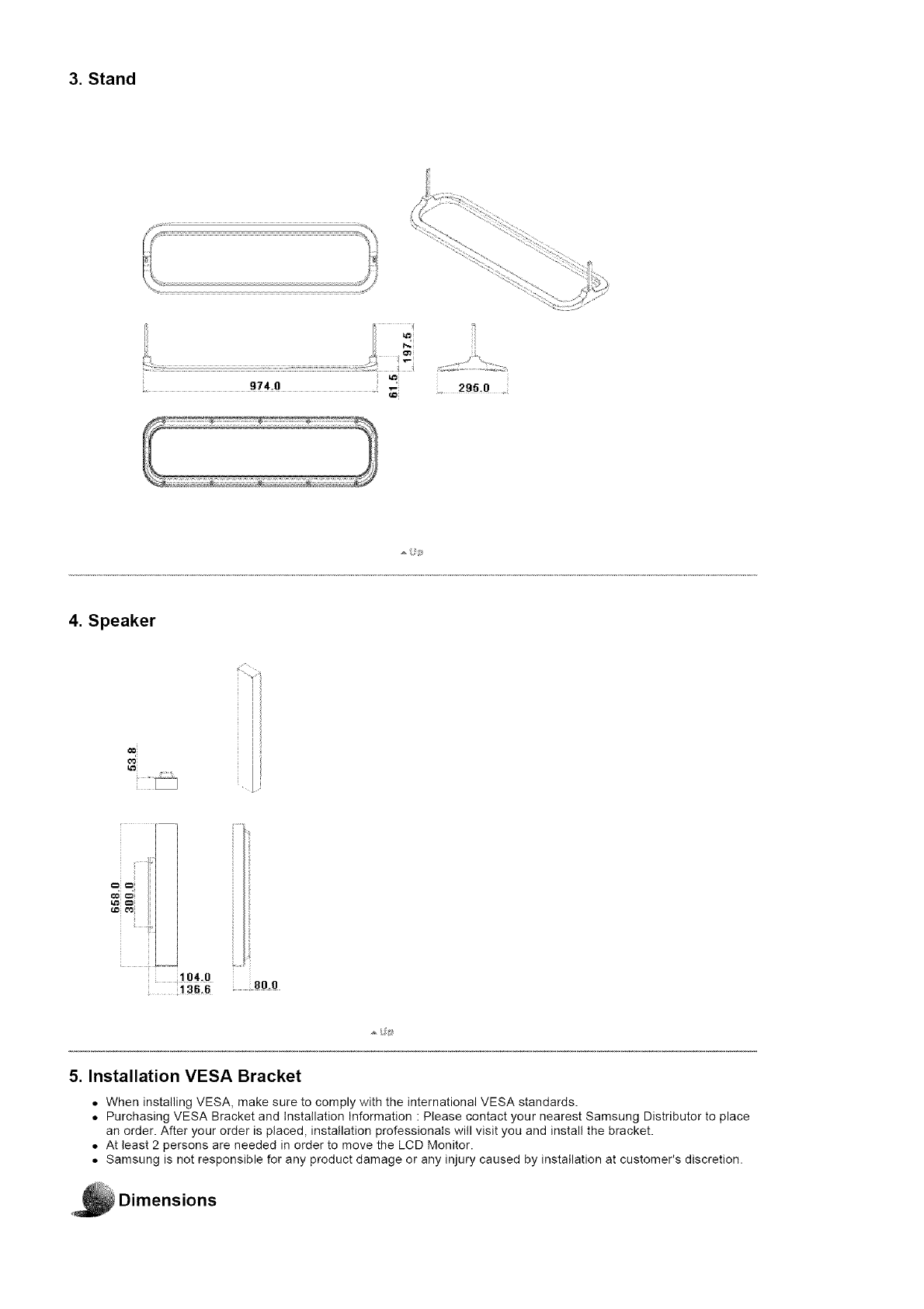
3. Stand
295.0 .
4. Speaker
==i==i
104 O 80.5
136.6
5. Installation VESA Bracket
• When installing MESA, make sure to comply with the international VESA standards.
• Purchasing VESA Bracket and Installation Information : Please contact your nearest Samsung Distributor to place
an order. After your order is placed, installation professionals will visit you and install the bracket.
• At least 2 persons are needed in order to move the LCD Monitor.
• Samsung is not responsible for any product damage or any injury caused by installation at customer's discretion•
Dimensions

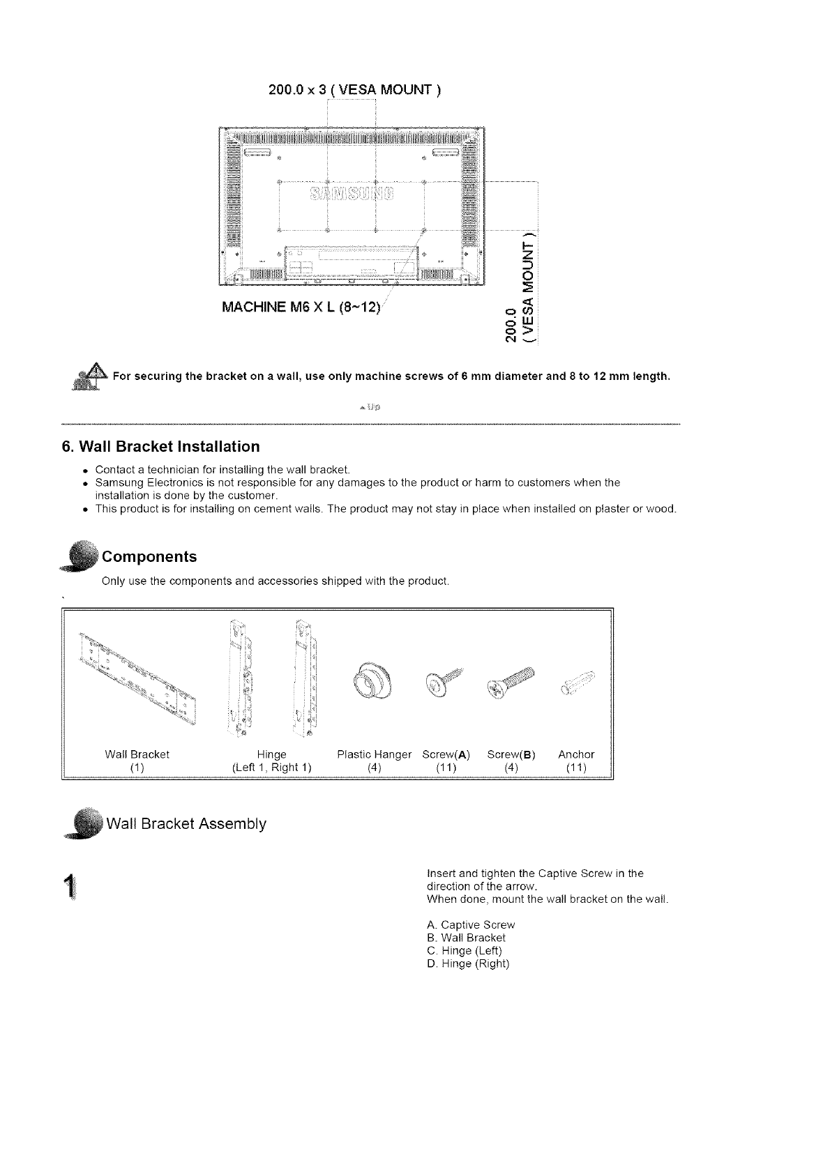
200.0 x 3( VES A MOUNT )
MACHINE M6 X L (8~t2)
Z
m
0
ow
For securing the bracket on a wall, use only machine screws of 6 mm diameter and 8 to 12 mm length.
6. Wall Bracket Installation
• Contact a technician for installing the wall bracket.
• Samsung Electronics is not responsible for any damages to the product or harm to customers when the
installation is done by the customer.
• This product is for installing on cement walls. The product may not stay in place when installed on plaster or wood.
i Components
Only use the components and accessories shipped with the product.
Wall Bracket
(1) Hinge Plastic Hanger Screw(A) Screw(B) Anchor
(Left 1, Right 1) (4) (11 ) (4) (1!)
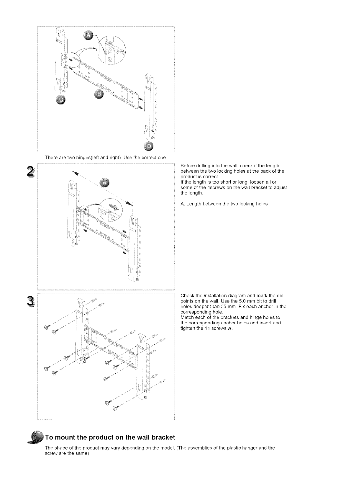
Wall Bracket Assembly
Insert and tighten the Captive Screw in the
direction of the arrow.
When done, mount the wall bracket on the wall.
A. Captive Screw
B. Wall Bracket
C. Hinge (Left)
D. Hinge (Right)

Therearetwohinges(leftandright).Usethecorrectone. Beforedrillingintothewall,checkifthelength
betweenthetwolookingholesatthebackofthe
productiscorrect•
Ifthelengthistooshortorlong,loosenallor
someofthe4screwsonthewallbrackettoadjust
thelength•
A.Lengthbetweenthetwolockingholes
y,•I
Check the installation diagram and mark the drill
points on the wall. Use the 5.0 mm bit to drill
holes deeper than 35 mm. Fix each anchor in the
corresponding hole.
Match each of the brackets and hinge holes to
the corresponding anchor holes and insert and
tighten the 11 screws A.
To mount the product on the wall bracket
The shape of the product may vary depending on the model. (The assemblies of the plastic hanger and the
screw are the same)

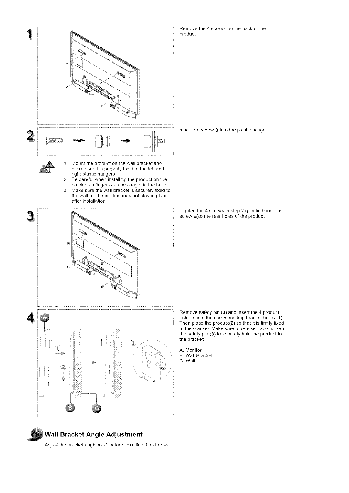
Removethe4screwsonthebackofthe
product.
InsertthescrewBintotheplastichanger.
1. Mounttheproductonthewailbracketand
makesureitisproperlyfixedtotheleftand
rightplastichangers.
2. Becarefulwheninstallingtheproductonthe
bracketasfingerscanbecaughtintheholes.
3. Makesurethewallbracketissecurelyfixedto
thewall,ortheproductmaynotstayinplace
afterinstallation.
Tightenthe4screwsinstep2(plastichanger+
screwB)totherearholesoftheproduct.
Removesafetypin(3)andinsertthe4product
holdersintothecorrespondingbracketholes(1).
Thenplacetheproduct(2)sothatitisfirmlyfixed
tothebracket.Makesuretore-insertandtighten
thesafetypin(3)tosecurelyholdtheproductto
thebracket.
A.Monitor
B.WallBracket
C.Wall
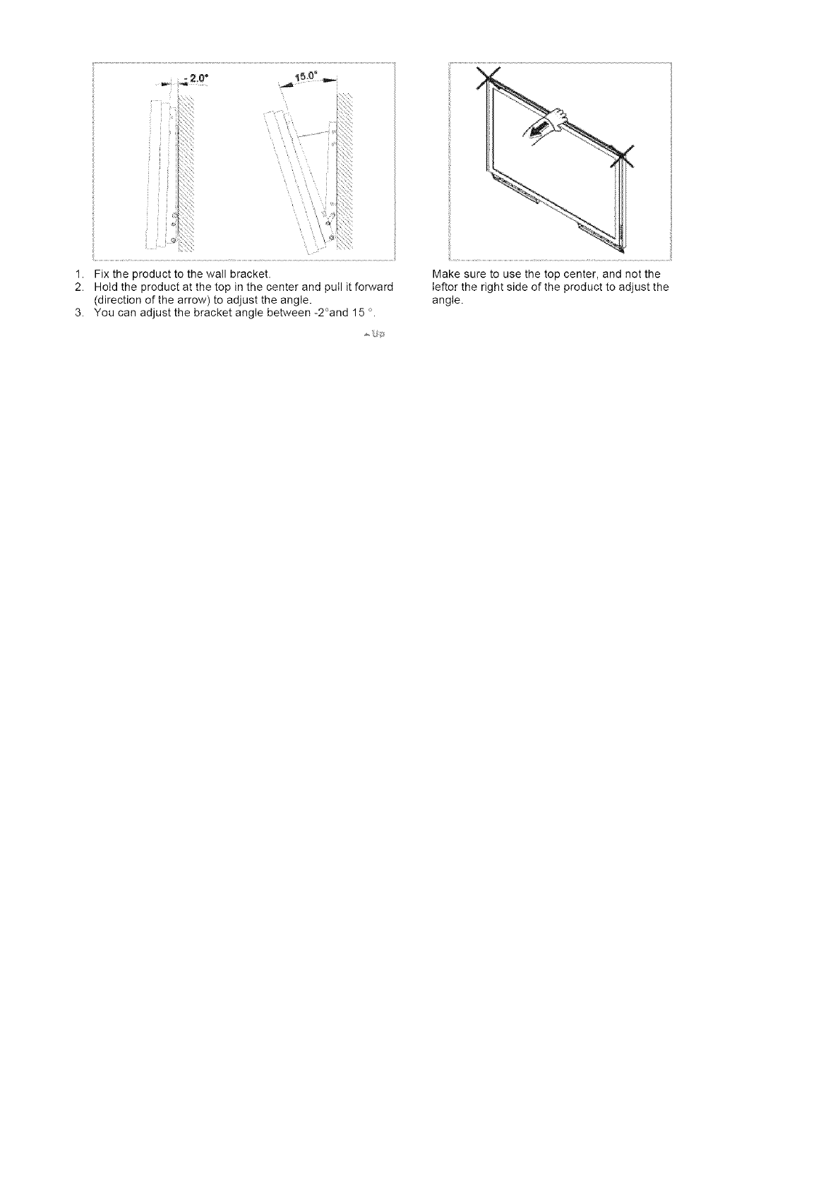
Wall Bracket Angle Adjustment
Adjust the bracket angle to -2°before installing it on the wall.
\
/
1. Fix the product to the wall bracket•
2. Hotd the product at the top in the center and pulI it forward
(direction of the arrow) to adjust the angle.
3. You can adjust the bracket angle between -2°and 15 o.
Make sure to use the top center, and not the
Ieftor the right side of the product to adjust the
angle.
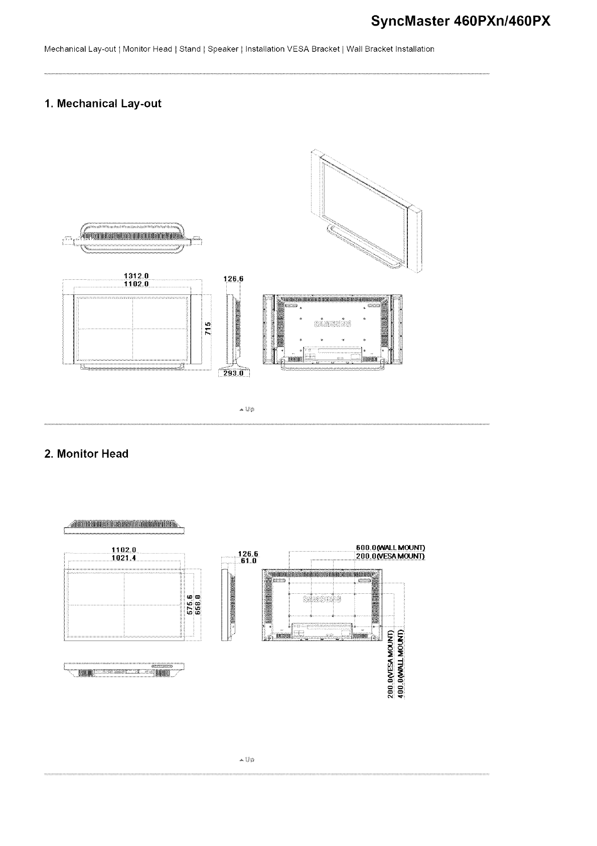
SyncMaster 460PXn/460PX
Mechanical Lay-out I Monitor Head t Stand LSpeaker LInstallation VESA Bracket I Wall Bracket Installation
1. Mechanical Lay-out
¢(
1312.0 126.6
i 11o20
i
2. Monitor Head
.... 1102.0
.... 1021.4 ..... !26.6
_I.0
i
2oo.o_MoJ_
8
_i _i _
3. Stand
295.0 .
4. Speaker
5. Installation VESA Bracket
• When installing MESA, make sure to comply with the international MESA standards.
• Purchasing VESA Bracket and Installation Information : Please contact your nearest Samsung Distributor to place
an order. After your order is placed, installation professionals will visit you and install the bracket.
• At least 2 persons are needed in order to move the LCD Monitor.
• Samsung is not responsible for any product damage or any injury caused by installation at customer's discretion•
Dimensions
200.0 x 3( VES A MOUNT )
MACHINE M6 X L (8~t2)
Z
m
0
ow
For securing the bracket on a wall, use only machine screws of 6 mm diameter and 8 to 12 mm length.
6. Wall Bracket Installation
• Contact a technician for installing the wall bracket.
• Samsung Electronics is not responsible for any damages to the product or harm to customers when the
installation is done by the customer.
• This product is for installing on cement walls. The product may not stay in place when installed on plaster or wood.
i Components
Only use the components and accessories shipped with the product.
Wall Bracket
(1) Hinge Plastic Hanger Screw(A) Screw(B) Anchor
(Left 1, Right 1) (4) (11 ) (4) (1!)
Wall Bracket Assembly
Insert and tighten the Captive Screw in the
direction of the arrow.
When done, mount the wall bracket on the wall.
A. Captive Screw
B. Wall Bracket
C. Hinge (Left)
D. Hinge (Right)
Therearetwohinges(leftandright).Usethecorrectone. Beforedrillingintothewall,checkifthelength
betweenthetwolockingholesatthebackofthe
productiscorrect•
Ifthelengthistooshortorlong,loosenallor
someofthe4screwsonthewallbrackettoadjust
thelength•
A.Lengthbetweenthetwolockingholes
y,•I
Check the installation diagram and mark the drill
points on the wall. Use the 5.0 mm bit to drill
holes deeper than 35 mm. Fix each anchor in the
corresponding hole.
Match each of the brackets and hinge holes to
the corresponding anchor holes and insert and
tighten the 11 screws A.
To mount the product on the wall bracket
The shape of the product may vary depending on the model. (The assemblies of the plastic hanger and the
screw are the same)
Removethe4screwsonthebackofthe
product.
InsertthescrewBintotheplastichanger.
1. Mounttheproductonthewailbracketand
makesureitisproperlyfixedtotheleftand
rightplastichangers.
2. Becarefulwheninstallingtheproductonthe
bracketasfingerscanbecaughtintheholes.
3. Makesurethewallbracketissecurelyfixedto
thewall,ortheproductmaynotstayinplace
afterinstallation.
Tightenthe4screwsinstep2(plastichanger+
screwB)totherearholesoftheproduct.
Removesafetypin(3)andinsertthe4product
holdersintothecorrespondingbracketholes(1).
Thenplacetheproduct(2)sothatitisfirmlyfixed
tothebracket.Makesuretore-insertandtighten
thesafetypin(3)tosecurelyholdtheproductto
thebracket.
A.Monitor
B.WallBracket
C.Wall
Wall Bracket Angle Adjustment
Adjust the bracket angle to -2°before installing it on the wall.

\
/
1. Fix the product to the wall bracket•
2. Hotd the product at the top in the center and pulI it forward
(direction of the arrow) to adjust the angle•
3. You can adjust the bracket angle between -2°and 15 o.
Make sure to use the top center, and not the
Ieftor the right side of the product to adjust the
angle.
Safety +r+atruct+ena
+nt++educt+on
Cen+_ect+er_s
Installing the Stand KIT
Connecting the LCD
Display
Uang the Seftwa_'e
Adjusting the LCD Disp ay
Troub_eshootir_g
Spec fieat e_s
Informat on
SyncMaster 400PXn/460PXn
._SelectLang _age Man Page
SyncMaster
ModeB
The color and appearance of the product may vary depending on the model and the product spedflcations are
subject to change without prior notice for reasons of performance enhancement.
Connections
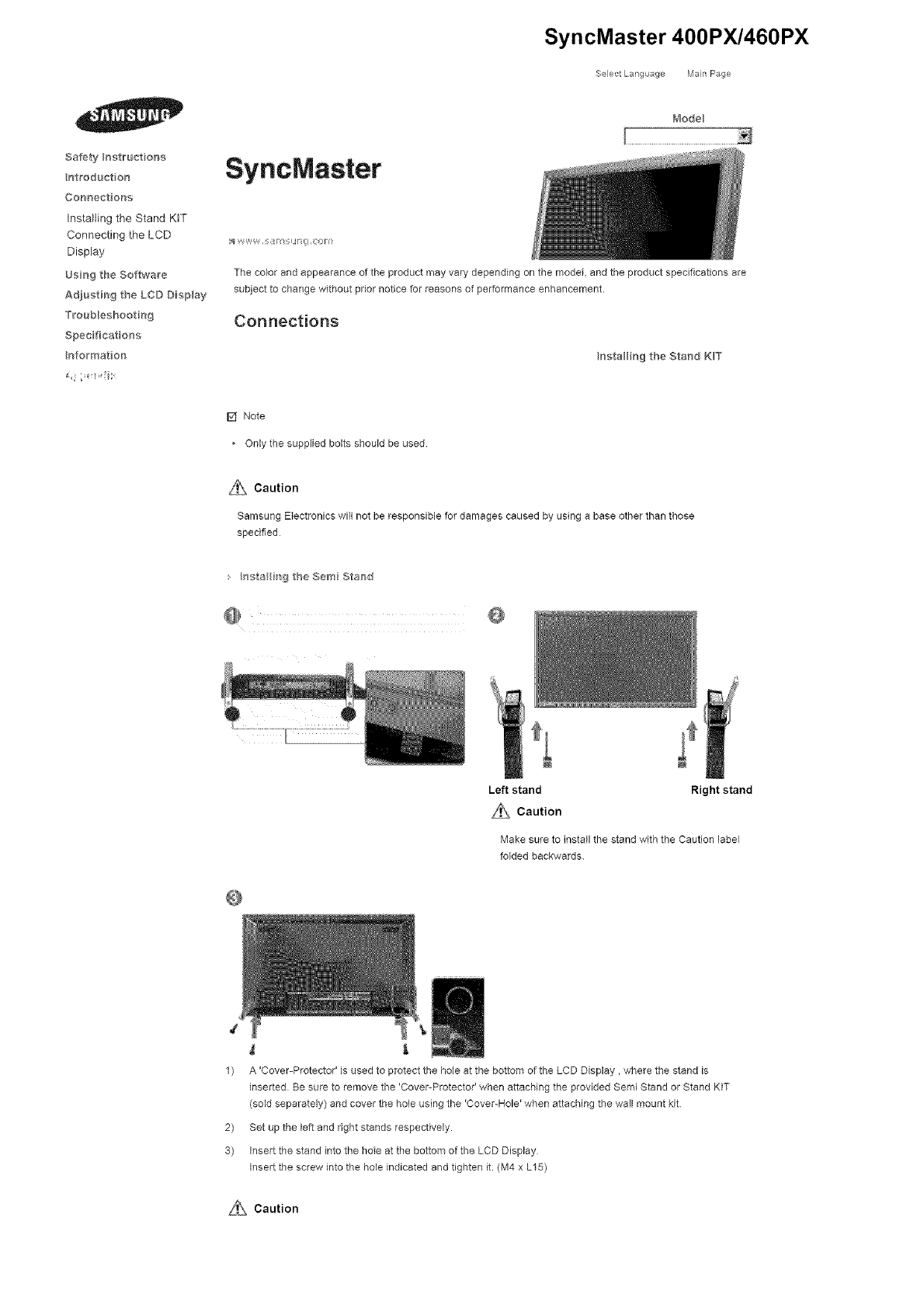
nataHing the Stand K_T
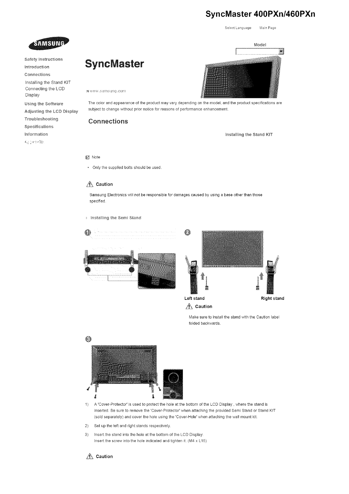
[] Note
• Only the supplied bolts should be used.
z{_ Caution
Samsung Electronics will not be responsible for damages caused by using a base other than those
specified
s hsta i_g the Sere Staw}d
@ @
Left stand Right stand
L_}_ Caution
Make sure to install the stand with the Caution label
folded backwards.
1) A 'Cover-Protector' is used to protect the hole at the bottom of the LCD Display, where the stand is
inserted Be sure to remove the 'Cover-Protector' when attaching the provided Semi Stand or Stand KIT
(sold separately) and cover the hole using the 'Cover-Hole' when attaching the wall mount kit
2) Set up the left and right stands respectively.
3) Insert the stand into the hole at the bottom of the LCD Display
Insert the screw into the hole indicated and tighten it. (M4 x L15)
Si}\ Caution
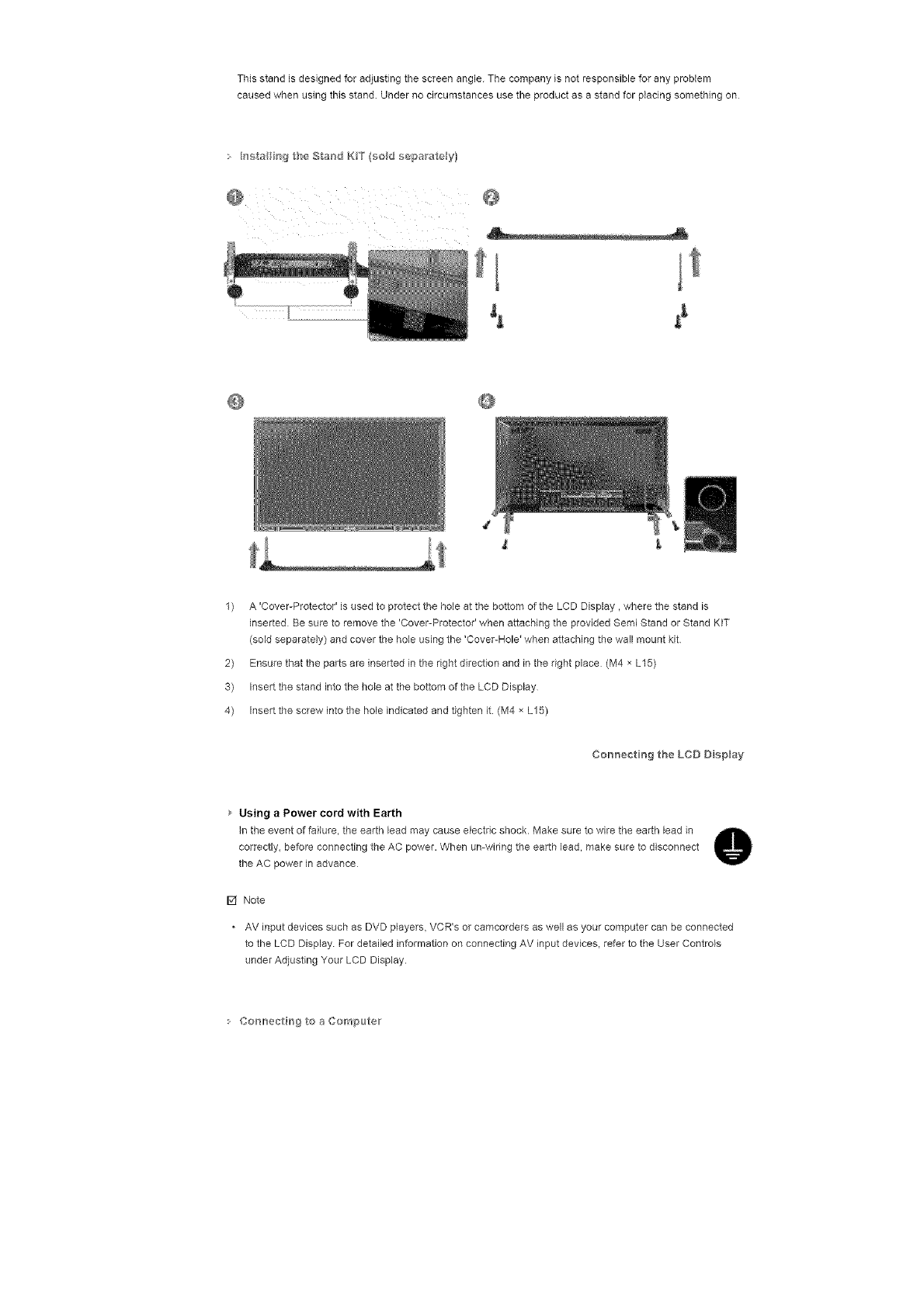
This stand is designed for adjusting the screen angle. The company is not responsible for any probtem
caused when using this stand. Under no circumstances use the product as a stand for pIadag something on
• hsta_ b'_g the Stand K_T (sod separate y}
@
t
1) A 'Cover-Protector' is used to protect the hole at the bottom of the LCD Display, where the stand is
inserted Be sure to remove the 'Cover-Protecto¢ when attaching the provided Semi Stand or Stand KIT
(sold separately) and cover the hole using the 'Cover-Hole' when attaching the wall mount kit
2) Ensure that the parts are inserted in the right direction and in the right place (M4 x L15)
3) Insert the stand into the hole at the bottom of the LCD Display
4) Insert the screw into the hole indicated and tighten it. (M4 × L15)
Cor_nectiHg the LCD D sp_ay
Using aPower cord with Earth
In the event of failure, the earth lead may cause electric shock• Make sure to wire the earth lead in
correctly, before connecting the AC power• When umwiring the earth lead, make sure to disconnect
the AC power in advance
F4 Note
AV input devices such as DVD players, VCR's or camcordars as well as your computer can be connected
to the LCD Display For detailed information on connecting AV input devices, refer to the User Controls
under Adjusting Your LCD Display•
Co_'_lr_ectirrsgto a Com_>uteir
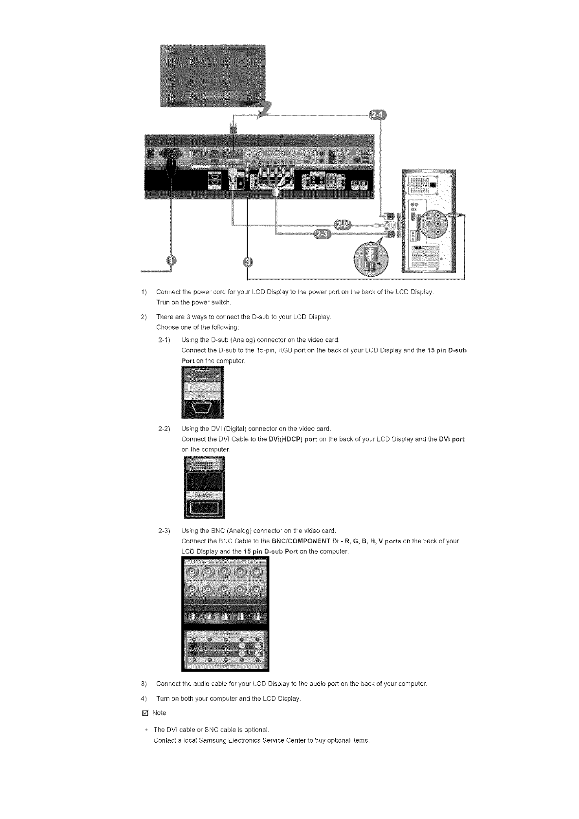
1)
2)
Connect the power cord for your LCD Display to the power port on the back of the LCD Display
Trun on the power switch
There are 3 ways to connect the D-sub to your LCD Display
Choose one of the following:
2-1) Using the D-sub (Analog) connector on the video card.
Connect the D-sub to the 15-pin, RGB port on the back of your LCD Display and the 15 pin D-sub
Port on the computer
2-2) Using the DVI (Digital) connector on the video card.
Connect the DVl Cable to the DVI(NDCP) port on the back of your LCD Display and the DVL port
on the computer.
2-3) Using the BNC (Analog) connector on the video card
Connect the BNC Cable to the BNCtCOMPONENT IN -R, G, B, N, V ports on the back of your
LCD Display end the 15 pin D-sub Port on the computer.
3) Connect the audio cable for your LCD Display to the audio port on the back of your computer
4) Turn on both your computer and the LCD Display.
F4 Note
• The DVI cable or BNC cable is optional
Contact a local Samsung Electronics Service Center to buy optional items

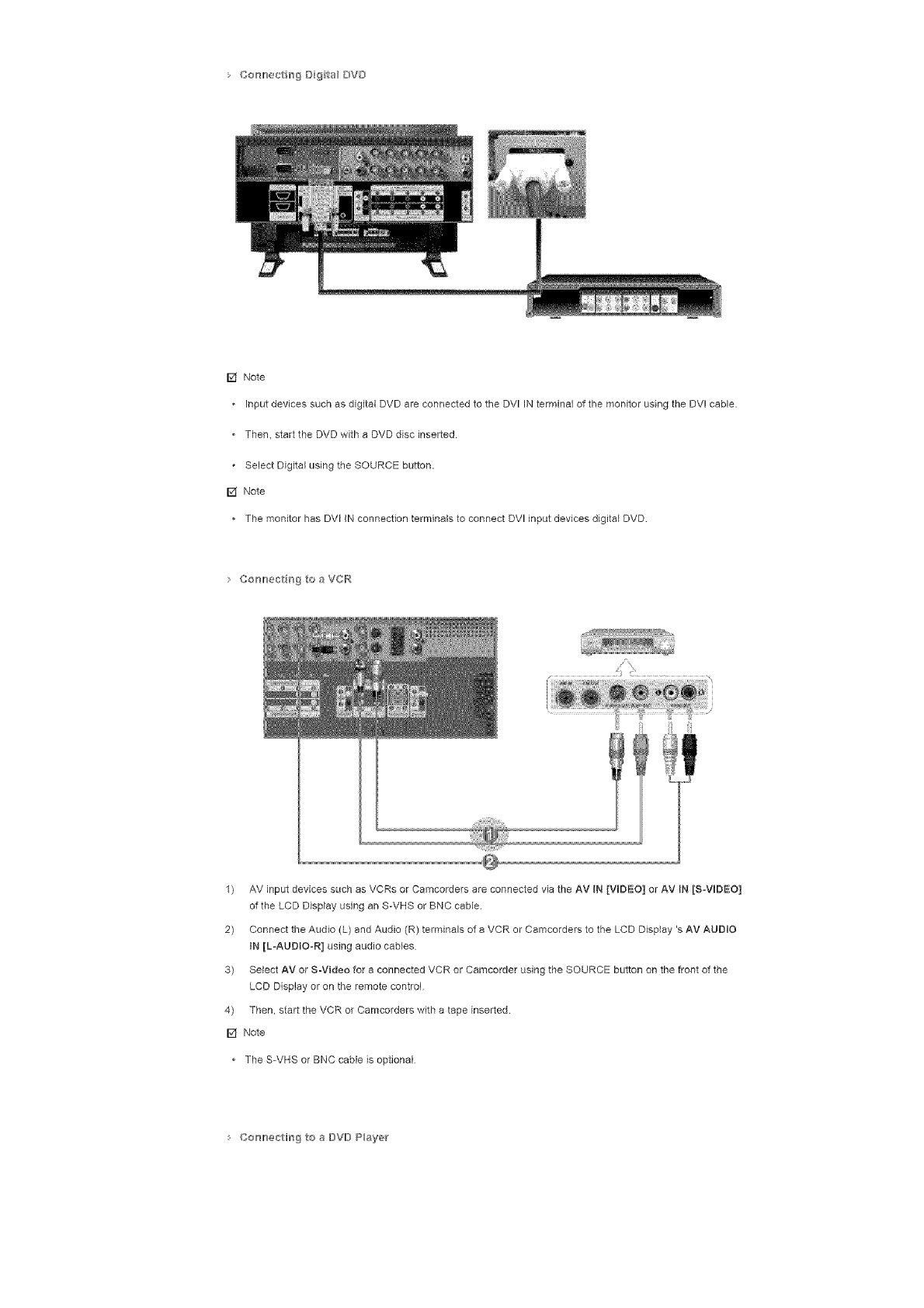
• Co_mer_trrs_B{_talBY[}
[] Note
• InputdevicessuchasdigitalDVDareconnectedtotheDVIINterminalofthemonitorusingtheDVIcable.
• Then,starttheDVDwithaDVDdiscinserted
SelectDigitalusingtheSOURCEbutton.
[] Note
ThemonitorhasDVIINconnectionterminalstoconnectDVlinputdevicesdigitalDVD
CorH}ect_gtoaVCt°¢
1) AVinputdevicessuchasVCRsorCamcordersareconnectedviatheAVIN[VIDEO]orAViN[SoViDEO]
oftheLCDDisplayusinganS-VHSorBNCcable.
2) ConnecttheAudio(L)andAudio(R)terminalsofaVCRorCamcorderstotheLCDDisplay'sAVAUDIO
IN[L-AUDIOoR]usingaudiocables
3) SelectAVorS-VideoforaconnectedVCRorCamcorderusingtheSOURCEbuttononthefrontofthe
LCDDisplayorontheremotecontrol
4) Then,starttheVCRorCamcorderswithatapeinserted.
[] Note
TheS-VHSorBNCcableisoptional
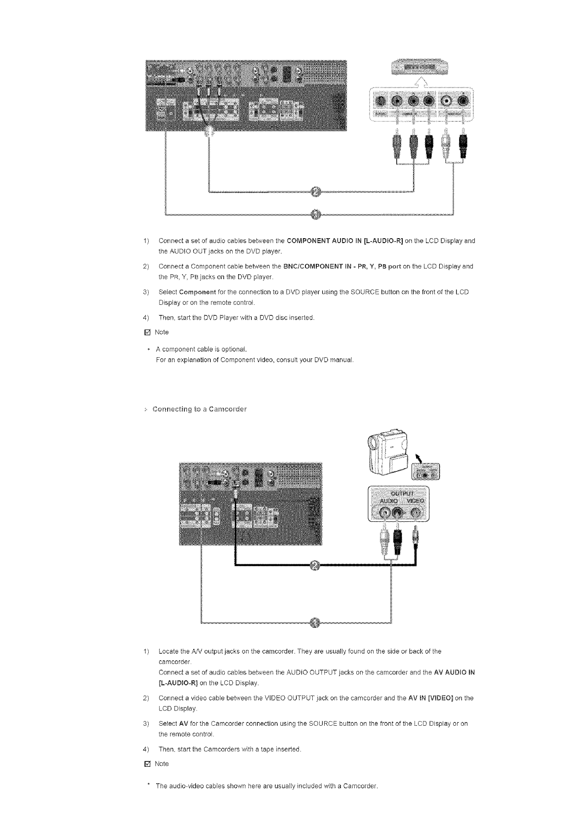
Co_'mecth_gtoaDVDP_ayer
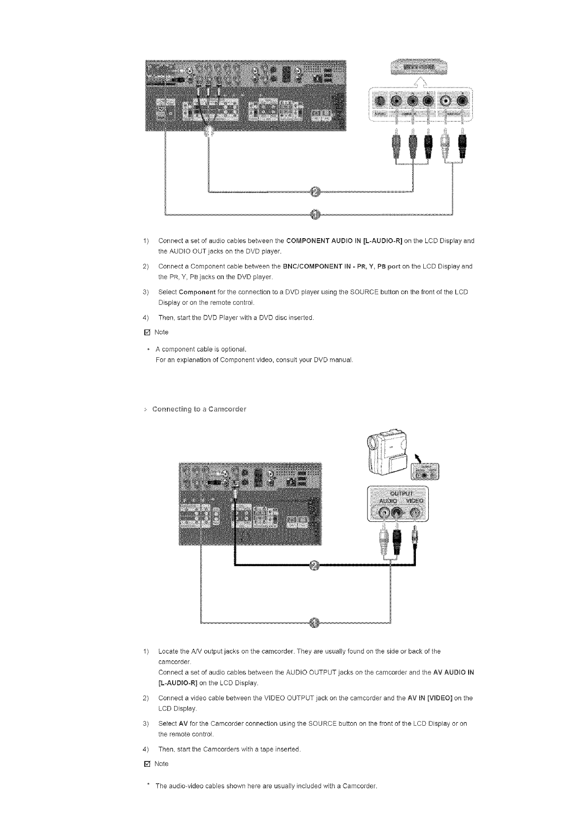
1) ConnectasetofaudiocablesbetweentheCOMPONENTAUDIOIN[LoAUDIOoR]ontheLCDDisplayand
theAUDIOOUTjacksontheDVDplayer.
2) ConnectaComponentcablebetweentheBNC/COMPONENTIN-PR,Y,PBportontheLCDDisplayand
thePR,Y,PBjacksontheDVDplayer.
3) SelectComponentfortheconnectiontoeDVDplayerusingtheSOURCEbuttononthefrontoftheLCD
Displayorontheremotecontrol.
4) Then,starttheDVDPlayerwitheDVDdiscinserted
[] Note
Acomponentcableisoptional.
ForanexplanationofComponentvideo,consultyourDVDmanual
Co_'_lr_ectirrsgtoaCamco,der
1) LocatetheA/VoutputjacksonthecamcorderTheyareusuallyfoundonthesideorbackofthe
camcorder
ConnectasetofaudiocablesbetweentheAUDIOOUTPUTjacksonthecamcorderandtheAVAUDIOiN
[L-AUDtOoR]ontheLCDDisplay
2) ConnectavideocablebetweentheVIDEOOUTPUTjackonthecamcorderandtheAVIN[VIDEO]onthe
LCDDisplay.
3) SelectAVfortheCamcorderconnectionusingtheSOURCEbuttononthefrontoftheLCDDisplayoron
theremotecontrol.
4) Then,starttheCamcorderswithatapeinserted.
[] Note
" Theaudio-videocablesshownhereareusuallyincludedwithaCamcorder.
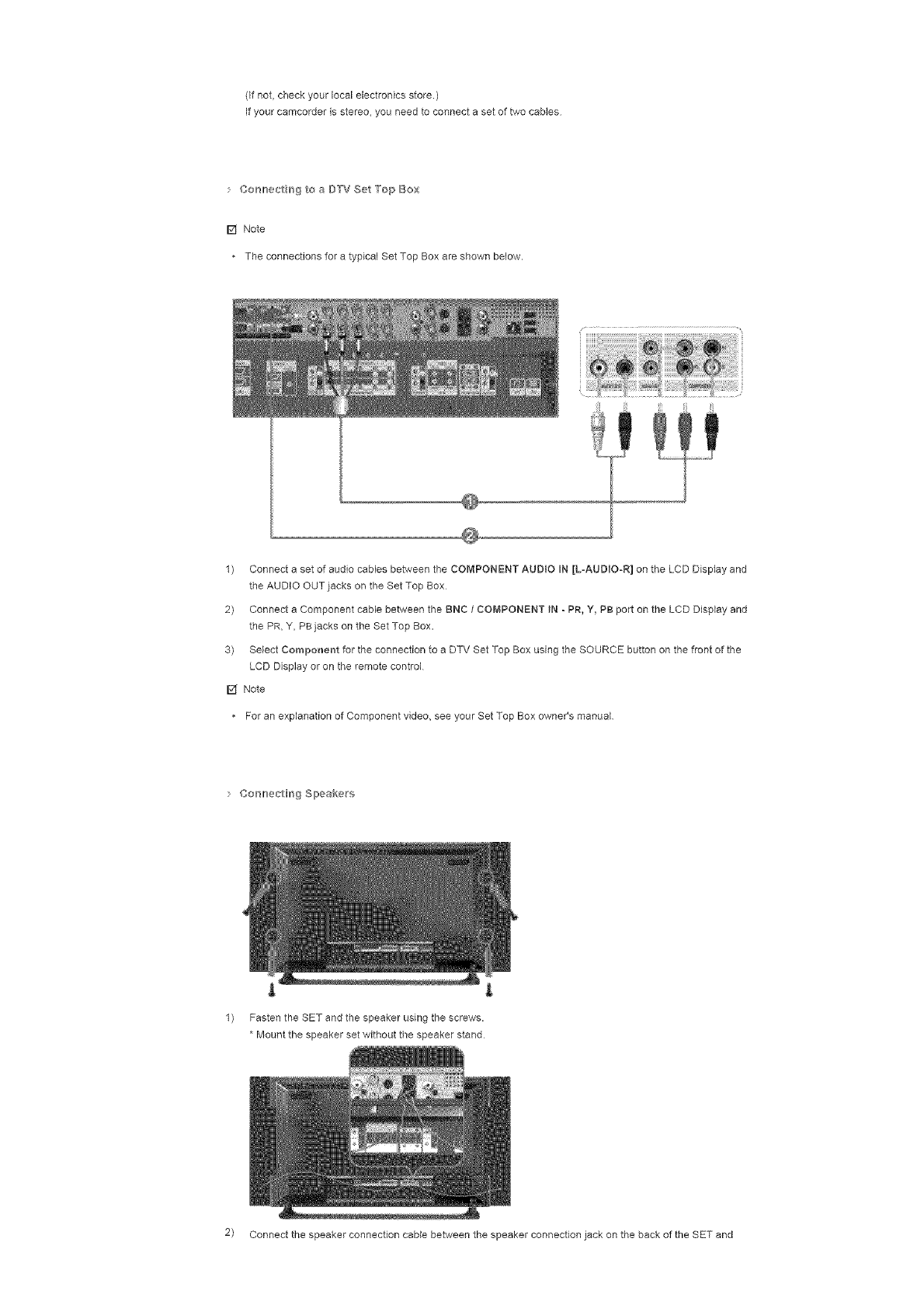
(Ifnot,checkyourlocalelectronicsstore.)
Ifyourcamcorderlsstereo+youneedtoconnectasetoftwocabMs
• Co_'_lr_÷c_rrsgtoaD'TVSet'TopBox
[] Note
+TheconnectionsforatypicalSetTopBoxareshownbelow.
1) ConnectasetofaudiocablesbetweentheCOMPONENTAUD+OIN[L=AUDIO-R]ontheLCDDisplayand
theAUDIOOUTjacksontheSetTopBox
2) ConnectaComponentcablebetweentheBNC1COMPONENT IN - PR, Y, PB port on the LCD Display and
the PR, Y, PB jacks on the Set Top Box.
3) SMect Component for the connection to a DTV Set Top Box using the SOURCE button on the front of the
LCD Display or on the remote control
[] Note
For an explanation of Component v+deo, see your Set Top Box owner's manual
Cosl_ec_Hng Slpeakers
l L
1) Fasten the SET and the speaker using the screws.
*Mount the speaker set without the speaker stand
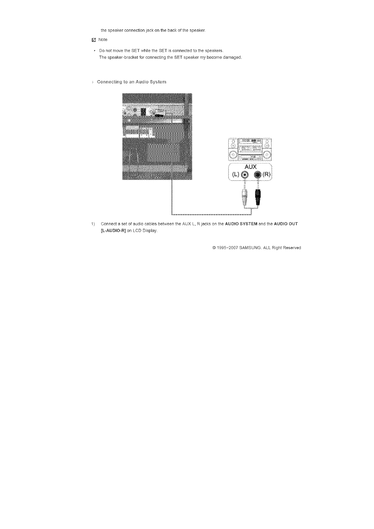
2) Connect the speaker connection came between the speaker connection jack on the back of the SET and
thespeakerconnectionjackonthebackofthespeaker.
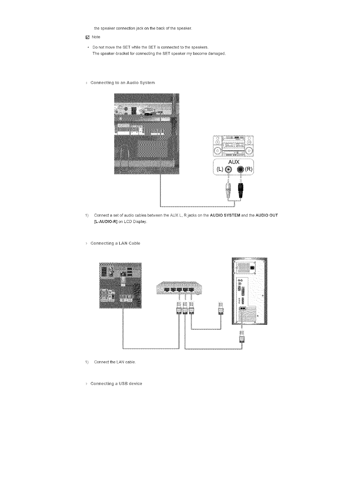
[] Note
DonotmovetheSETwhiletheSETisconnectedtothespeakers.
Thespeaker-bracketforconnectingtheSETspeakermybecomedamaged.
Co_'_lr_ectirrs9toa_'tAudoSy_,tem
1) ConnectasetofaudiocablesbetweentheAUXL,RjacksontheAUDIOSYSTEMandtheAUDIOOUT
[LoAUDtOoR]onLCDDisplay.
: Co_'_lr_ec_FrogaLAH Cabe
1) Connect the LAN cable.
:Cor_lr_ec_Hfr_9aL_SB devce
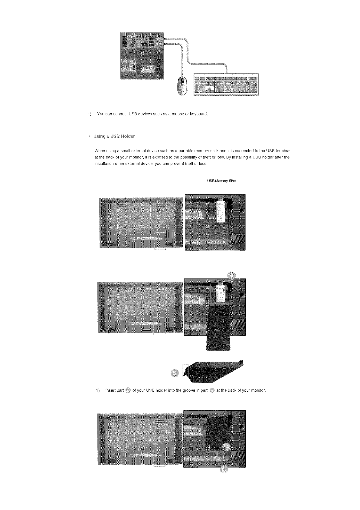
1) YoucanconnectUSBdevicessuchasamouseorkeyboard.
Using a USB Holder
When using a small external device such as a portable memory stick and it is connected to the USB terminal
at the back of your monitor, it is exposed to the possiblity of theft or loss. By installing a USB holder after the
installation of an external device, you can prevent theft or loss.
UBB Merrmr_, $t_c_
1) insert part of your USB holder into the groove in part at the back of your monitor
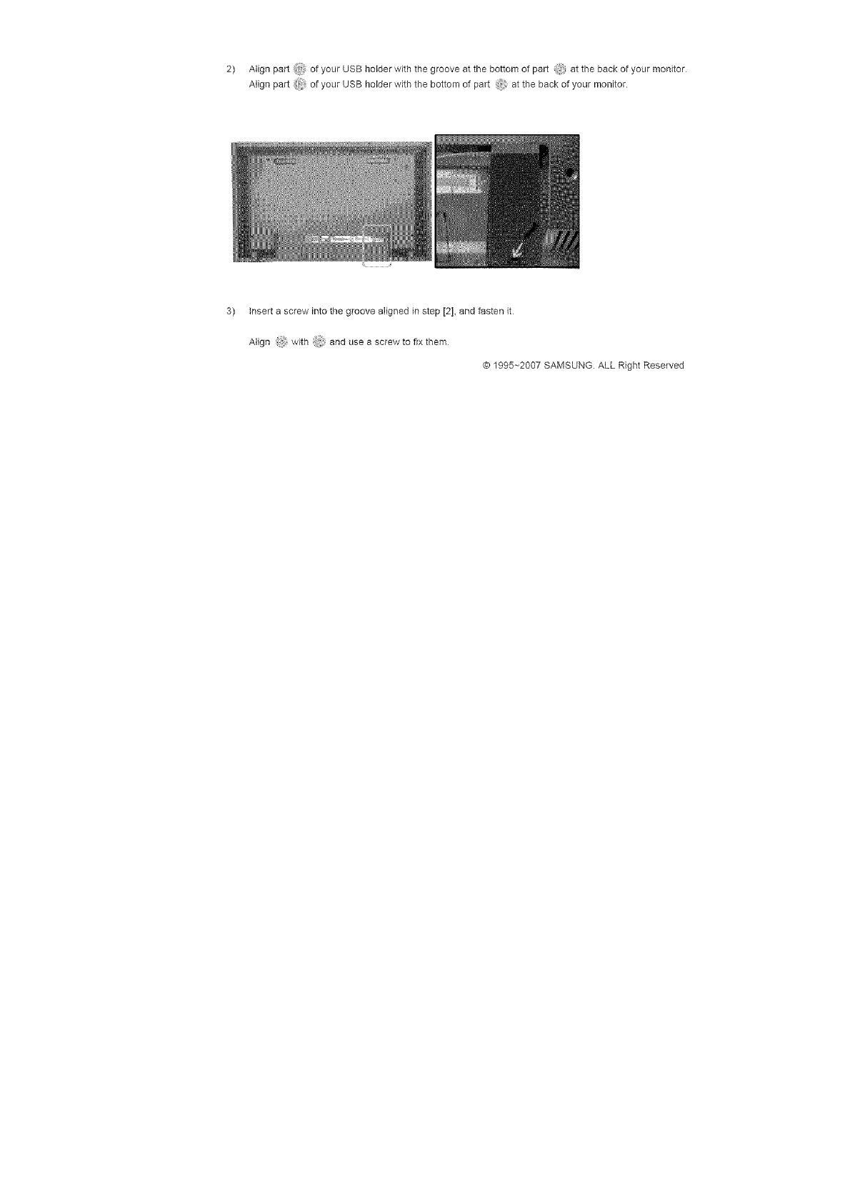
2) Alignport_i:ofyourUSBholderwiththegrooveatthebottomofpart atthebackofyourmonitor
Alignpart_ ofyourUSBholderwiththebottomofpart,_,atthebackofyourmonitor.
3) insertascrewintothegroovealignedinstep[2],andfastenit
Align with'i anduseascrewtofixthem
@1995-+2007SAMSUNGALLRightReserved
Safety+r+atruct+ena
+nt++educt+on
Cen+_ect+er_s
Installing the Stand KIT
Connecting the LCD
Display
Uang the Seftwa_'e
Adjusting the LCD Disp ay
Troub_eshootir_g
Spec fieat e_s
Informat on
SyncMaster 400PX/460PX
._SelectLang _age Man Page
SyncMaster
ModeB
The color and appearance of the product may vary depending on the model and the product spedflcations are
subject to change without prior notice for reasons of performance enhancement.
Connections
nataHing the Stand K_T
[] Note
• Only the supplied bolts should be used.
z{_ Caution
Samsung Electronics will not be responsible for damages caused by using a base other than those
specified
s hsta i_g the Sere Staw}d
@ @
Left stand Right stand
L_}_ Caution
Make sure to install the stand with the Caution label
folded backwards.
1) A 'Cover-Protector' is used to protect the hole at the bottom of the LCD Display, where the stand is
inserted Be sure to remove the 'Cover-Protector' when attaching the provided Semi Stand or Stand KIT
(sold separately) and cover the hole using the 'Cover-Hole' when attaching the wall mount kit
2) Set up the left and right stands respectively.
3) Insert the stand into the hole at the bottom of the LCD Display
Insert the screw into the hole indicated and tighten it. (M4 x L15)
Si}\ Caution

This stand is designed for adjusting the screen angle. The company is not responsible for any probtem
caused when using this stand. Under no circumstances use the product as a stand for pIadag something on
• hsta_ b'_g the Stand K_T (sod separate y}
@
t
1) A 'Cover-Protector' is used to protect the hole at the bottom of the LCD Display, where the stand is
inserted Be sure to remove the 'Cover-Protecto¢ when attaching the provided Semi Stand or Stand KIT
(sold separately) and cover the hole using the 'Cover-Hole' when attaching the wall mount kit
2) Ensure that the parts are inserted in the right direction and in the right place (M4 x L15)
3) Insert the stand into the hole at the bottom of the LCD Display
4) Insert the screw into the hole indicated and tighten it. (M4 × L15)
Cor_nectiHg the LCD D sp_ay
Using aPower cord with Earth
In the event of failure, the earth lead may cause electric shock• Make sure to wire the earth lead in
correctly, before connecting the AC power• When umwiring the earth lead, make sure to disconnect
the AC power in advance
F4 Note
AV input devices such as DVD players, VCR's or camcordars as well as your computer can be connected
to the LCD Display For detailed information on connecting AV input devices, refer to the User Controls
under Adjusting Your LCD Display•
Co_'_lr_ectirrsgto a Com_>uteir

1)
2)
Connect the power cord for your LCD Display to the power port on the back of the LCD Display
Trun on the power switch
There are 3 ways to connect the D-sub to your LCD Display
Choose one of the following:
2-1) Using the D-sub (Analog) connector on the video card.
Connect the D-sub to the 15-pin, RGB port on the back of your LCD Display and the 15 pin D-sub
Port on the computer
2-2) Using the DVI (Digital) connector on the video card.
Connect the DVl Cable to the DVI(NDCP) port on the back of your LCD Display and the DVL port
on the computer.
2-3) Using the BNC (Analog) connector on the video card
Connect the BNC Cable to the BNC/COMPONENT IN -R, G, B, N, V ports on the back of your
LCD Display end the 15 pin D-sub Port on the computer.
3) Connect the audio cable for your LCD Display to the audio port on the back of your computer
4) Turn on both your computer and the LCD Display.
F4 Note
• The DVI cable or BNC cable is optional
Contact a local Samsung Electronics Service Center to buy optional items
• Co_mer_trrs_B{_talBY[}
[] Note
• InputdevicessuchasdigitalDVDareconnectedtotheDVIINterminalofthemonitorusingtheDVIcable.
• Then,starttheDVDwithaDVDdiscinserted
SelectDigitalusingtheSOURCEbutton.
[] Note
ThemonitorhasDVIINconnectionterminalstoconnectDVlinputdevicesdigitalDVD
CorH}ect_gtoaVCt°¢
1) AVinputdevicessuchasVCRsorCamcordersareconnectedviatheAVIN[VIDEO]orAViN[SoViDEO]
oftheLCDDisplayusinganS-VHSorBNCcable.
2) ConnecttheAudio(L)andAudio(R)terminalsofaVCRorCamcorderstotheLCDDisplay'sAVAUDIO
IN[L-AUDIOoR]usingaudiocables
3) SelectAVorS-VideoforaconnectedVCRorCamcorderusingtheSOURCEbuttononthefrontofthe
LCDDisplayorontheremotecontrol
4) Then,starttheVCRorCamcorderswithatapeinserted.
[] Note
TheS-VHSorBNCcableisoptional
Co_'mecth_gtoaDVDP_ayer
1) ConnectasetofaudiocablesbetweentheCOMPONENTAUDIOIN[LoAUDIOoR]ontheLCDDisplayand
theAUDIOOUTjacksontheDVDplayer.
2) ConnectaComponentcablebetweentheBNC/COMPONENTIN-PR,Y,PBportontheLCDDisplayand
thePR,Y,PBjacksontheDVDplayer.
3) SelectComponentfortheconnectiontoeDVDplayerusingtheSOURCEbuttononthefrontoftheLCD
Displayorontheremotecontrol.
4) Then,starttheDVDPlayerwitheDVDdiscinserted
[] Note
Acomponentcableisoptional.
ForanexplanationofComponentvideo,consultyourDVDmanual
Co_'_lr_ectirrsgtoaCamco,der
1) LocatetheA/VoutputjacksonthecamcorderTheyareusuallyfoundonthesideorbackofthe
camcorder
ConnectasetofaudiocablesbetweentheAUDIOOUTPUTjacksonthecamcorderandtheAVAUDIOiN
[L-AUDtOoR]ontheLCDDisplay
2) ConnectavideocablebetweentheVIDEOOUTPUTjackonthecamcorderandtheAVIN[VIDEO]onthe
LCDDisplay.
3) SelectAVfortheCamcorderconnectionusingtheSOURCEbuttononthefrontoftheLCDDisplayoron
theremotecontrol.
4) Then,starttheCamcorderswithatapeinserted.
[] Note
" Theaudio-videocablesshownhereareusuallyincludedwithaCamcorder.

(Ifnot,checkyourlocalelectronicsstore.)
Ifyourcamcorderisstereo,youneedtoconnectasetoftwocables
• Co_'_lr_÷c_rrsgtoaD'TVSet'TopBox
[] Note
• TheconnectionsforatypicalSetTopBoxareshownbelow.
1) ConnectaComponentcablebetweentheBNC/COMPONENT iN oPR, Y, PB port on the LCD Display and
the PR, Y, PBiacks ORthe Set Top Box.
2) Connect a set of audio cables between the COMPONENT AUDIO IN [LoAUDIOoR] on the LCD Display and
the AUDIO OUTjacks on the Set Top Box.
3) Select Component for the connection to a DTV Set Top Box using the SOURCE button on the front of the
LCD Display or on the remote control
[] Note
For an explanation of Component video, see your Set Top Box owner's manual
Cosl_ec_Hng Slpeakers
l L
1) Fasten the SET and the speaker using the screws.
*Mount the speaker set without the speaker stand
2) Connect the speaker connection cable between the speaker connection jack on the back of the SET and
thespeakerconnectionjackonthebackofthespeaker
[] Note
DonotmovetheSETwhiletheSETisconnectedtothespeakers.
Thespeaker-bracketforconnectingtheSETspeakermybecomedamaged.
Co_,}ecth_9toasAudoSy_;tem
1) ConnectasetofaudiocablesbetweentheAUXL,RjacksontheAUDIOSYSTEMandtheAUDIOOUT
[L-AUDIO-R]onLCDDisplay.
© 1995~2007 SAMSUNG. ALL Right Reserved
SyncMaster 400PXn/460PXn
Select Lang _age Man Page
Safety I_structo_s
ntroduction
Connect ons
Usng the Software
Installation MagicNet
MDC
MagicNet
Adjusting the LCD Disp ay
Troub_eshootin 9
Spec ficat ons
fnformat on
SyncMaster
t_'_odel
The color and appearance of the product may vary depending on the model and the product specifications are
subject to change without prior notice for reasons of performance enhancement.
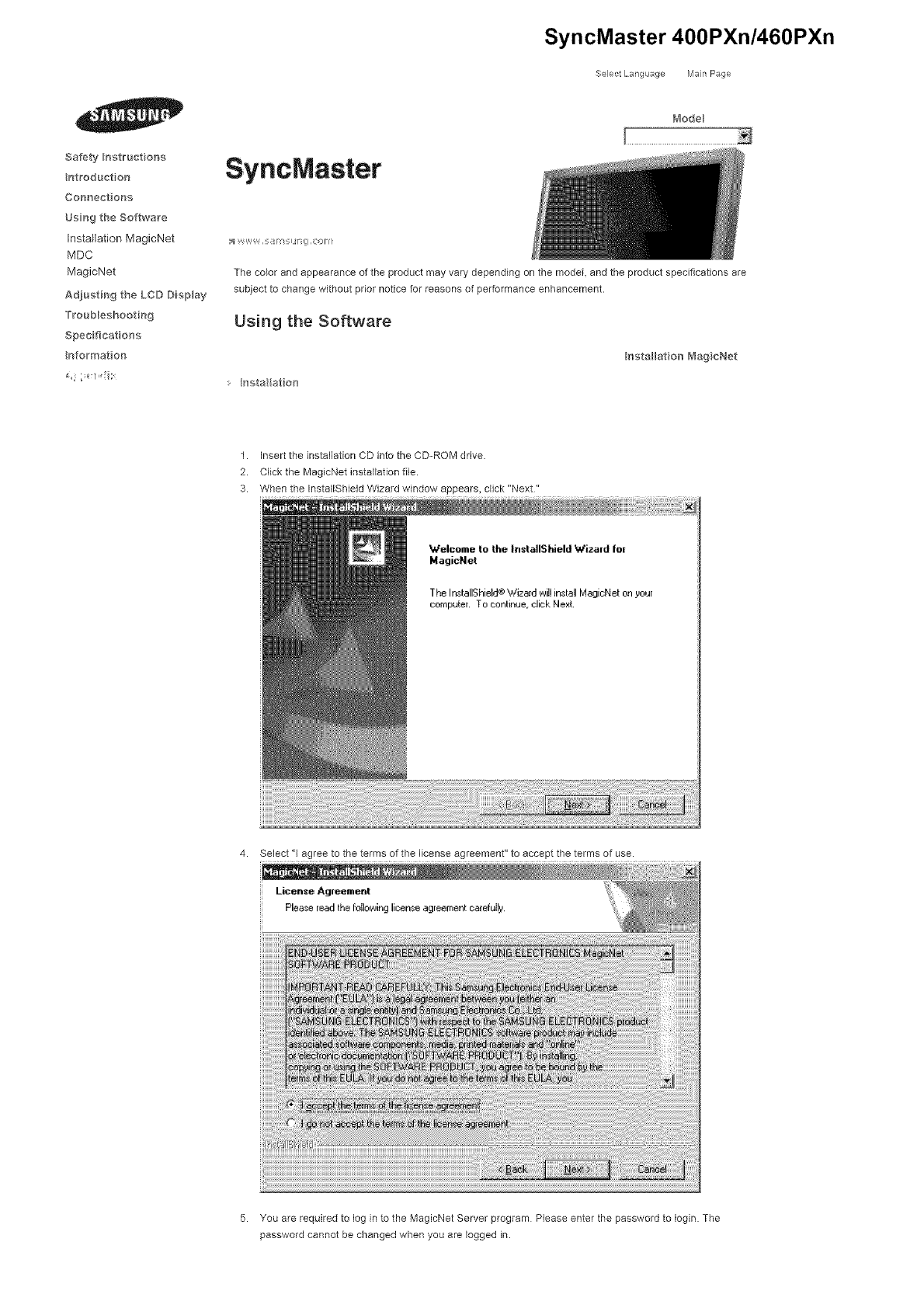
Using the Software
:. hsta at on
Installation Meg cNet
1. insert the installation CD into the CD-ROM drive.
2. Click the MagicNet installation file.
3. When the InstallShield Wizard window appears, click "Next"
4. Select "1 agree to the terms of the license agreement" to accept the terms of use.
License Agreement
Plee,<;eread the followinglicense agreement carefully,
5. You are required to log in to the MagicNet Server program Please enter the password to Iogin. The
password cannot be changed when you are logged in.
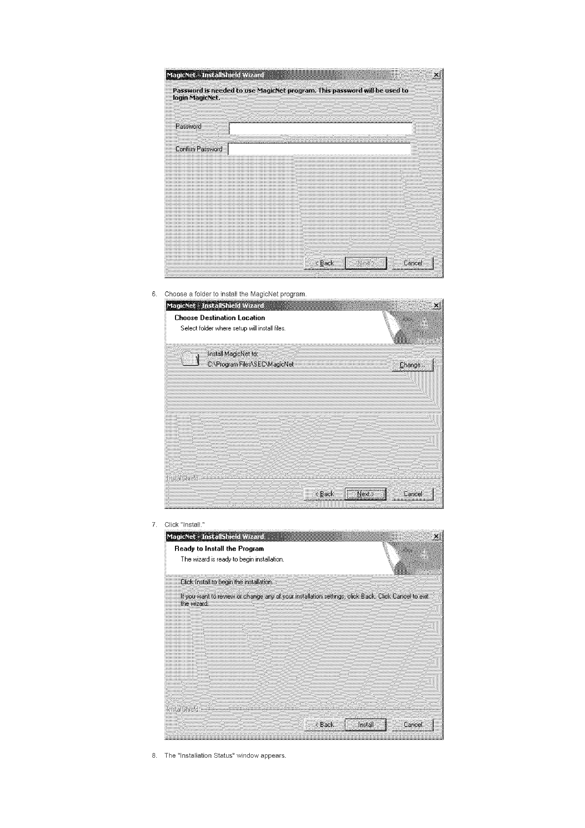
6. ChooseafoldertoinstalltheMagicNetprogram.
ChooseDestination Location
Select folder where setup ,A,ill install files.
7. Click "install."
Read9 to Install the Program
The wizardis ready to begin installation.
8. The "lnstaflation Status" window appears
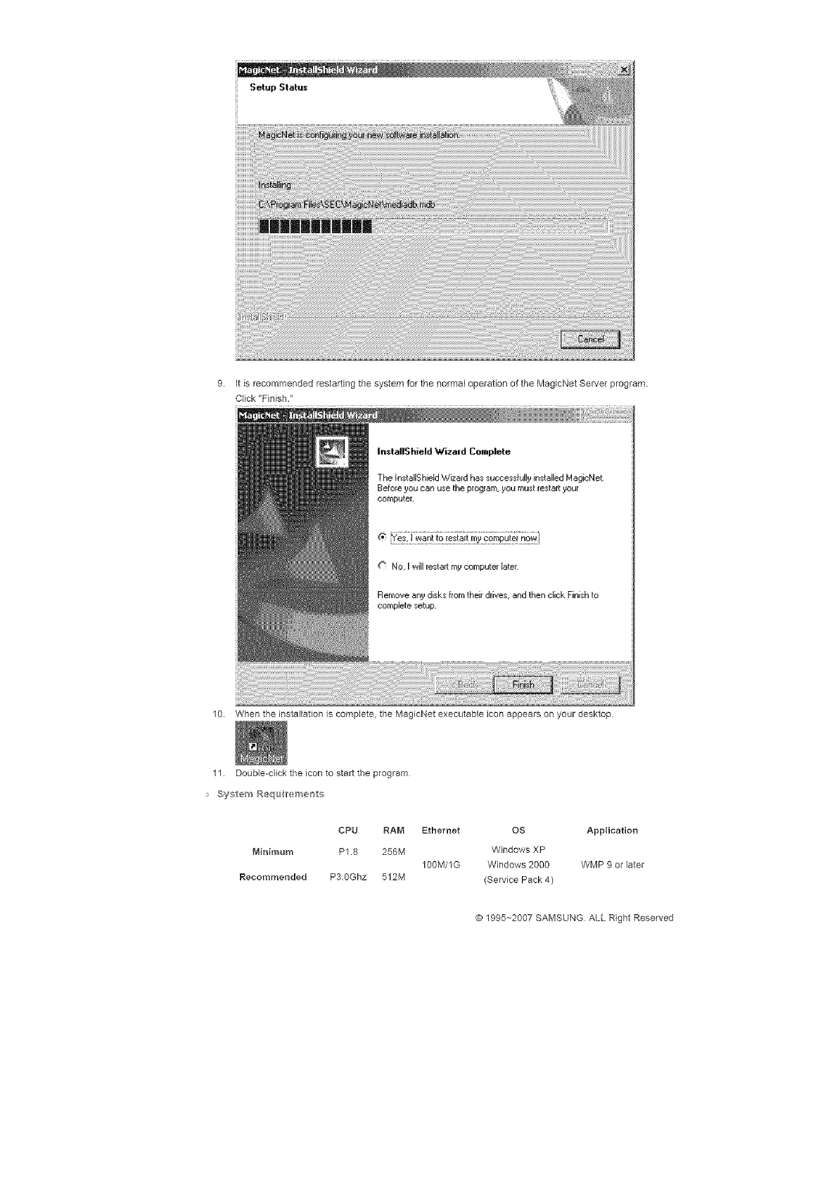
Setup Statu_
9. It is recommended restarting the system for the normal operation of the MagicNet Server program.
Click "Finish."
In_tallShield W'izmd Complete
The InstallS hield Wizard has successfully installed MagicNet
Befo[e you can use the program, you must restart your
eornputei.
10. When the installation is complete, the MagicNet executable icon appears on your desktop
11. Double=click the icon to start the program
System Requ Ireme_ts
CPV RAM Ethernet OS Application
Minimum P1.8 256M Windows XP
100lYi/1G Windows 2000 WMP 9 or later
Recommended P3 0Ghz 512M (Service Pack 4)
© 1995--2007 SAMSU_x_G ALL Right Reserved
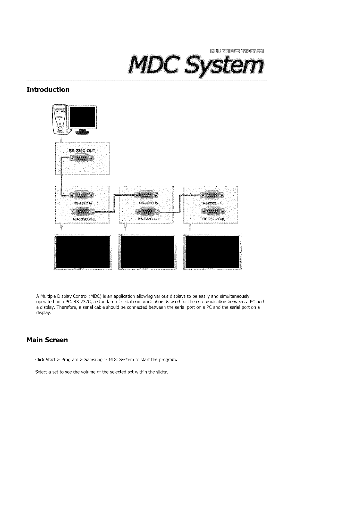
Introduction
A Multiple Display Control (MDC) is an application allowing various displays to be easily and simultaneously
operated on a PC. RS-232C, a standard of serial communication, is used for the communication between a PC and
a display. Therefore, a serial cable should be connected between the serial port on a PCand the serial port on a
display,
Main Screen
Click Start > Program > Samsung > MDC System to start the program.
Select a set to see the volume of the selected set within the slider,
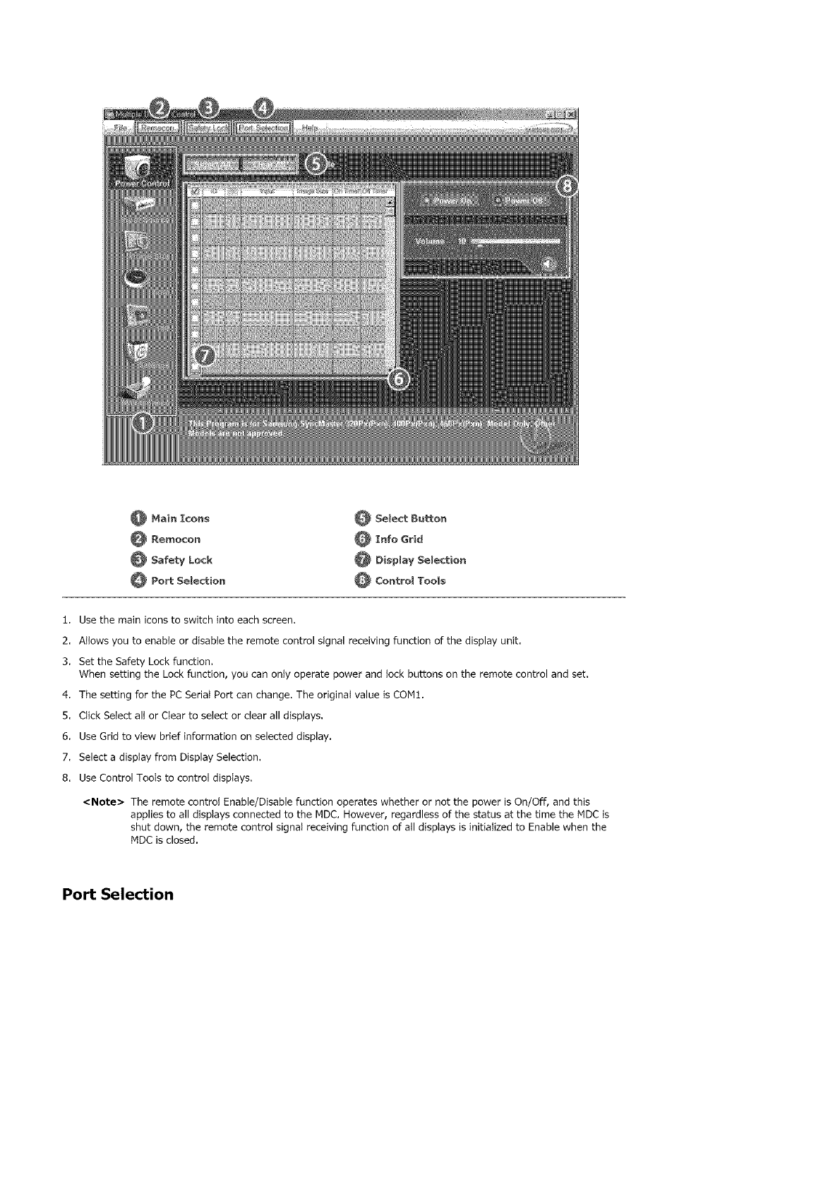
_Main Icons
@ Rel_%ocon
_Safety Lock
_Port SeBection
_Select Button
_Info Grid
_ Display Selection
_Contro_ Tools
1. Use the main icons to switch into each screen.
2. Allows you to enable or disable the remote control signal receiving function of the display unit.
3. Set the Safety Lock function.
When setting the Lock function, you can onty operate power and lock buttons on the remote control and set.
4. The setting for the PC Serial Port can change. The original value is COM1.
5. Click SeIect alt or Clear to seIect or clear all displays.
6. Use Grid to view brief information on selected display.
7. Select a display from Display Selection.
8. Use Control Tools to control displays.
<Note> The remote control Enable/Disable function operates whether or not the power is On/Off, and this
applies to all displays connected to the MDC. However, regardless of the status at the time the MDC is
shut down, the remote control signal receiving function of all displays is initialized to Enable when the
MDC is closed.
Port Selection
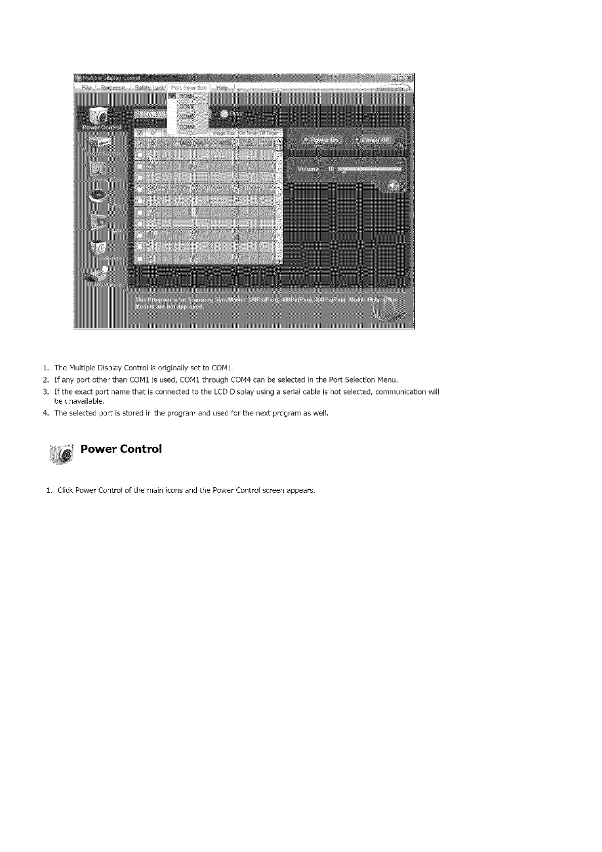
1. The Muttipte Disptay Controt is originally set to CON1.
2. If any port other than CON1 is used, CON1 through CON4 can be selected in the Port Selection Menu.
3. If the exact port name that is connected to the LCD Display using a serial cable is not seIected, communication will
be unavailable.
4. The seIected port isstored in the program and used for the next program as weIt.
Power Control
1. Click Power Control of the main icons and the Power Control screen appears.
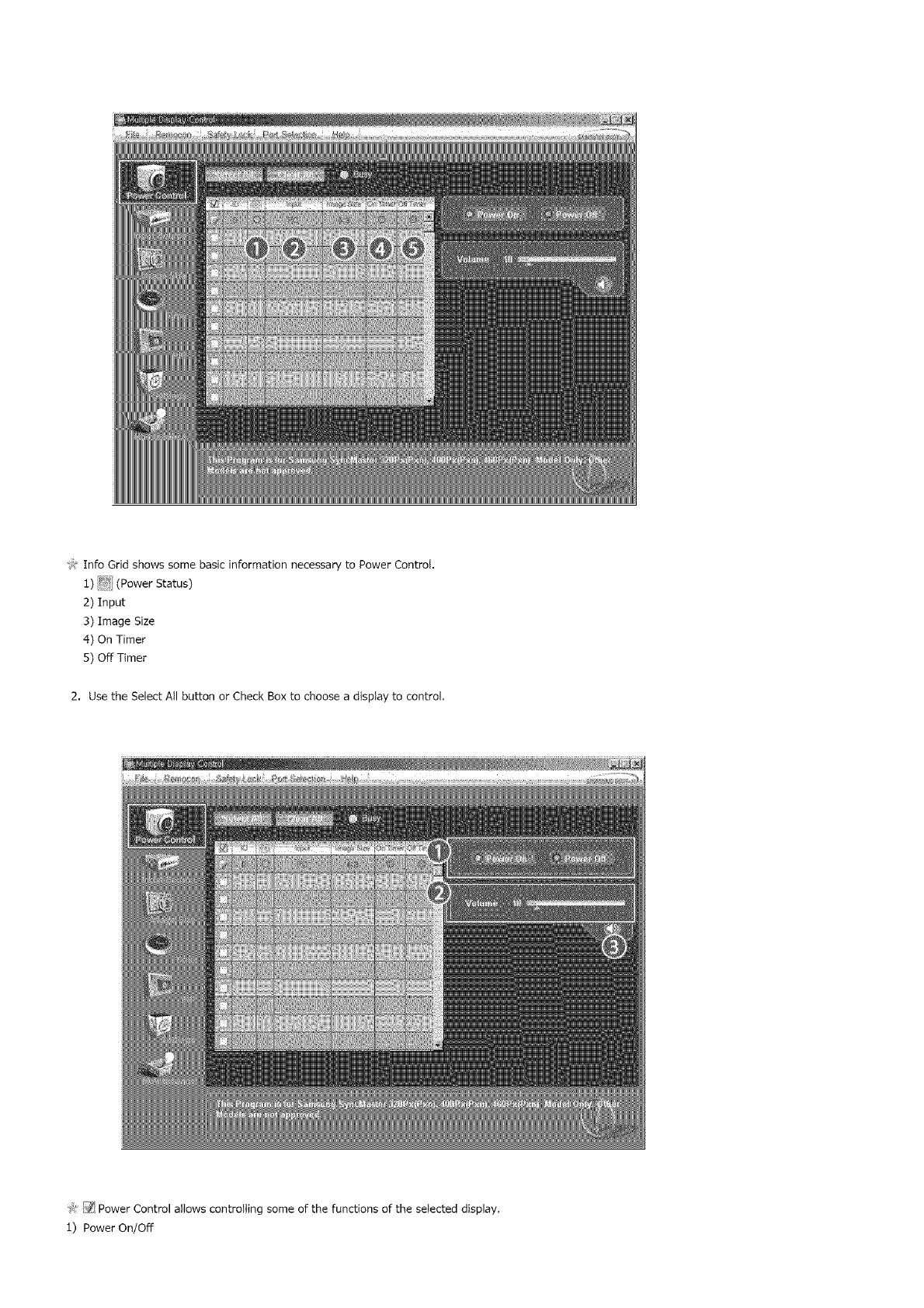
>_InfoGridshowssomebasicinformationnecessarytoPowerControl.
1)_ (PowerStatus)
2)Input
3)ImageSize
4)OnTimer
5)OffTimer
2. UsetheSelectAllbuttonorCheckBoxtochooseadisplaytocontrol.
'_:!_:_PowerControlattowscontrollingsomeofthefunctionsoftheselecteddisplay.
1)PowerOn/Off
-TurnsthepoweroftheselecteddisplayOn/Off.
2)Volume
-Controlsthevolumeleveloftheselecteddisplay.
Itreceivesthevolumevalueoftheselecteddisplayfromthesetsanddisplaysitintheslider.
(WhenyoucanceltheselectionorchooseSelectAll,thevaluereturnstothedefaultvalue10)
3)_ (MuteOn/Off)
-Turnson/offtheMutefunctionoftheselecteddisplay.
Whenselectingonesetatatime,turnontheMutefunctionfortheselectedset.
TheMutefunctionisdisabledautomaticallywhenyouadjustthevolumelevel.
(Thevaluesreturntothedefaultsettingswhenyouundotheselectionsorchoose"SelectAll".)
The Power Control feature is available for all displays,
The Volume Control and Mute features are available only for the displays whose power status is ON.
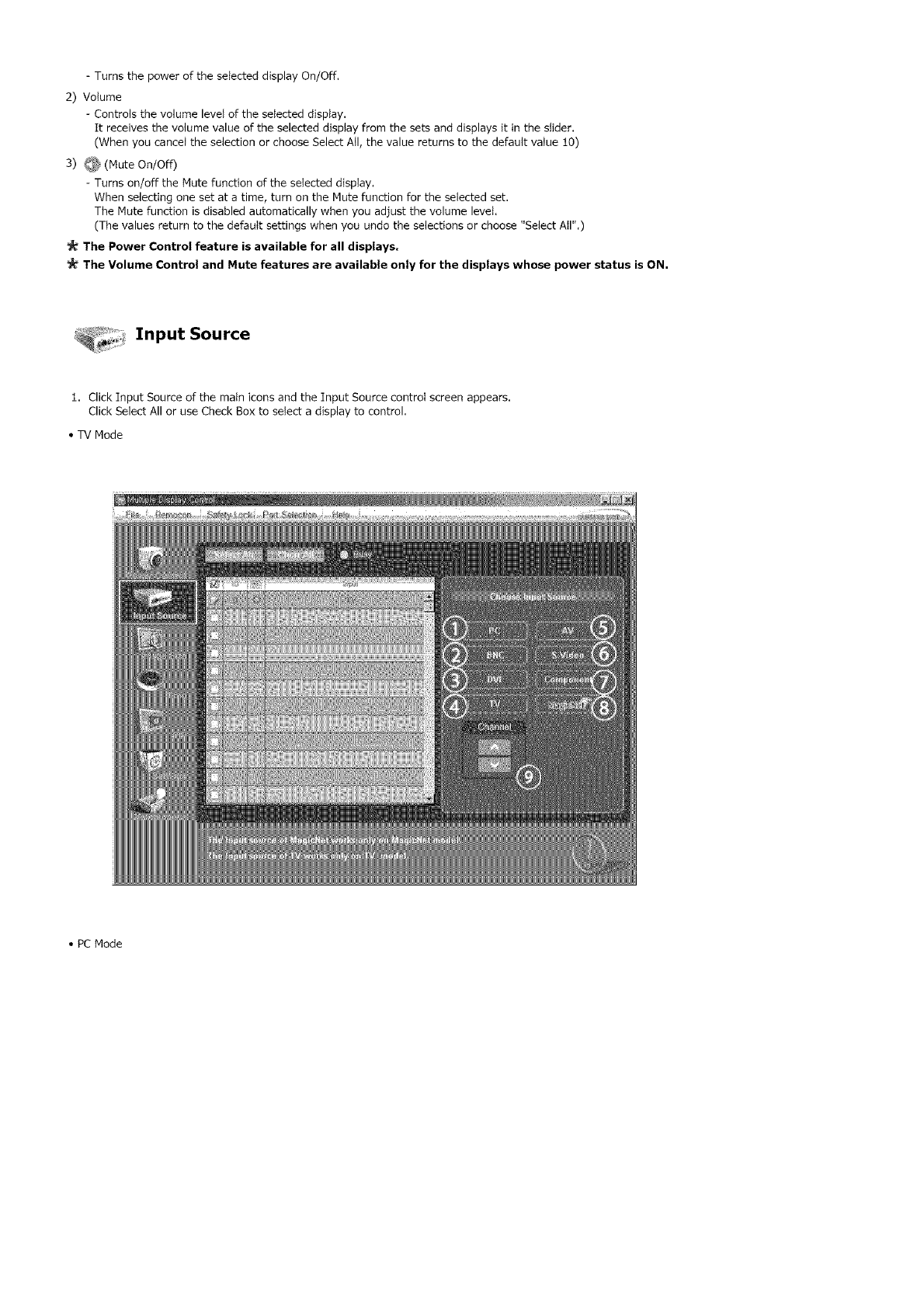
, _, Input Source
1. Click Input Source of the main icons and the Input Source control screen appears.
Click Select All or use Check Box to select a display to control.
•TV Mode
•PC Mode
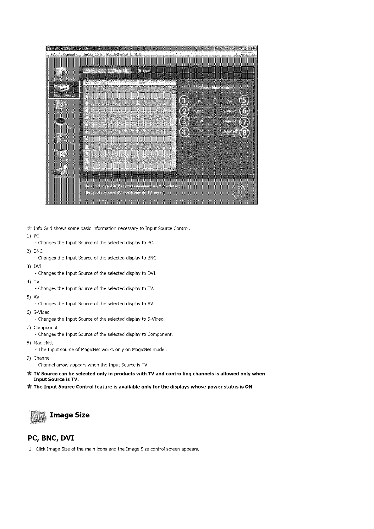
Jt Info Grid shows some basic information necessary to Input Source Control.
1) PC
Changes the Input Source of the selected display to PC,
2) BNC
Changes the Input Source of the selected display to BNC,
3) DVI
Changes the Input Source of the selected display to DVI.
4) TV
Changes the Input Source of the selected display to TV.
5) AV
Changes the Input Source of the selected display to AV,
6) S-Video
Changes the Input Source of the selected display to S-Video.
7) Component
Changes the Input Source of the selected display to Component.
8) MagicNet
The Input source of MagicNet works only on MagicNet model.
9) Channel
Channel arrow appears when the Input Source is TV.
TV Source can be selected only in products with TV and controlling channels is allowed only when
Input Source is TV,
The input Source Control feature is available only for the displays whose power status is ON,
Image Size
PC, BNC, DVI
1. Click Image Size of the main icons and the Image Size control screen appears.
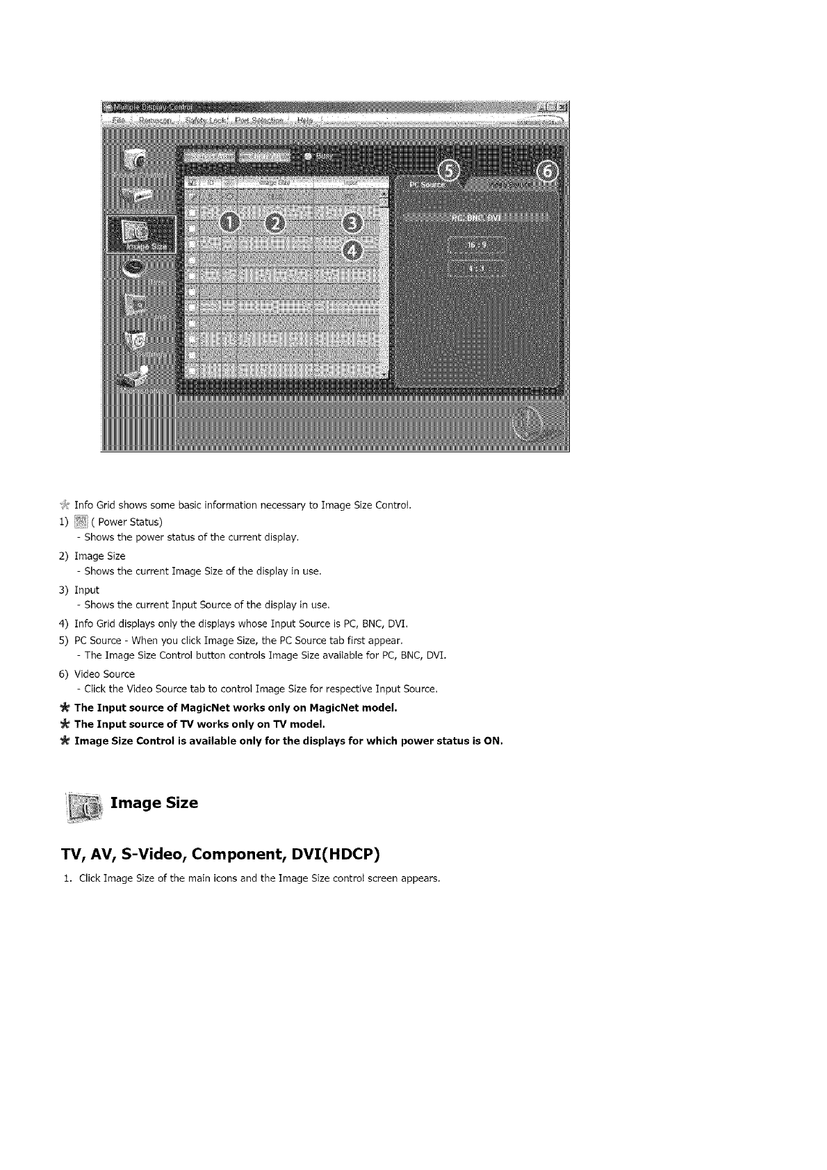
J:InfoGridshowssomebasicinformationnecessarytoImageSizeControt.
:l)_ ( PowerStatus)
- Showsthepowerstatusofthecurrentdisplay.
2)ImageSize
- ShowsthecurrentImageSizeof:thedisplayinuse.
3)Input
- ShowsthecurrentInputSourceofthedisplayinuse.
4)InfoGriddisplaysonlythedisptayswhoseInputSourceisPC,BNC,DVI.
5)PCSource-WhenyouclickImageSize,thePCSourcetabfirstappear.
-TheImageSizeControlbuttoncontrolsImageSizeavaitableforPC,BNC,DVI.
6)VideoSource
-ClicktheVideoSourcetabtocontroIImageSizeforrespectiveInputSource.
The Input source of MagicNet works only on MagicNet model,
The Input source of TV works only on TV model.
_!_ Image Size Control is available only for the displays for which power status is ON.
Image Size
TV, AV, S-Video, Component, DVI(HDCP)
1. Click Image Size of the main icons and the Image Size controt screen appears.
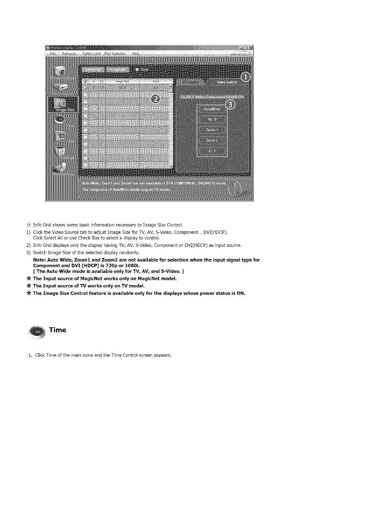
J: [nfo Grid shows some basic information necessary to Image Size Control.
1) Click the Video Source tab to adjust Image Size for TV, AV, S-Video, Component., DVI(HDCP).
Click Select All or use Check Box to select a display to control.
2) Info Grid displays only the display having TV, AV, S-Video, Component or DVI(HDCP) as input source.
3) Switch Image Size of the selected display randomly.
Note" Auto Wide_ Zoom1 and Zoom2 are not available for selection when the input signal type for
Component and DVI (HDCP) is 720p or 1080i.
( The Auto Wide mode is available only for TV IAVr and S-Video. )
The Input source of MagicNet works only on MagicNet model.
The Input source of TV works only on TV model.
The Image Size Control feature is available only for the displays whose power status is ON.
Time
1. Click Time of the main icons and the Time Control screen appears,
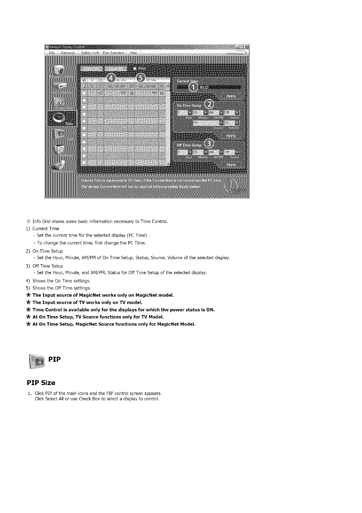
J:InfoGridshowssomebasicinformationnecessarytoTimeControI.
1)CurrentTime
- Setthecurrenttimefortheselecteddisplay(PCTime),
-Tochangethecurrenttime,firstchangethePCTime.
2)OnTimeSetup
- SettheHour,Minute,AM/PMofOnTimeSetup,Status,Source,VolumeoftheselecteddispIay,
3)OffTimeSetup
- SettheHour,Minute,andAM/PM,StatusforOffTimeSetupoftheselecteddisplay.
4)ShowstheOnTimesettings.
S)ShowstheOffTimesettings.
The Input source of MagicNet works only on MagicNet model,
The Input source of TV works only on TV model,
Time Control is available only for the displays for which the power status is ON.
At On Time Setup, TV Source functions only for TV Model.
At On Time Setup, MagicNet Source functions only for MagicNet Model.
PIP
PIP Size
1. Click PIP of the main icons and the PIP control screen appears.
Click Select All or use Check Box to select a display to control,
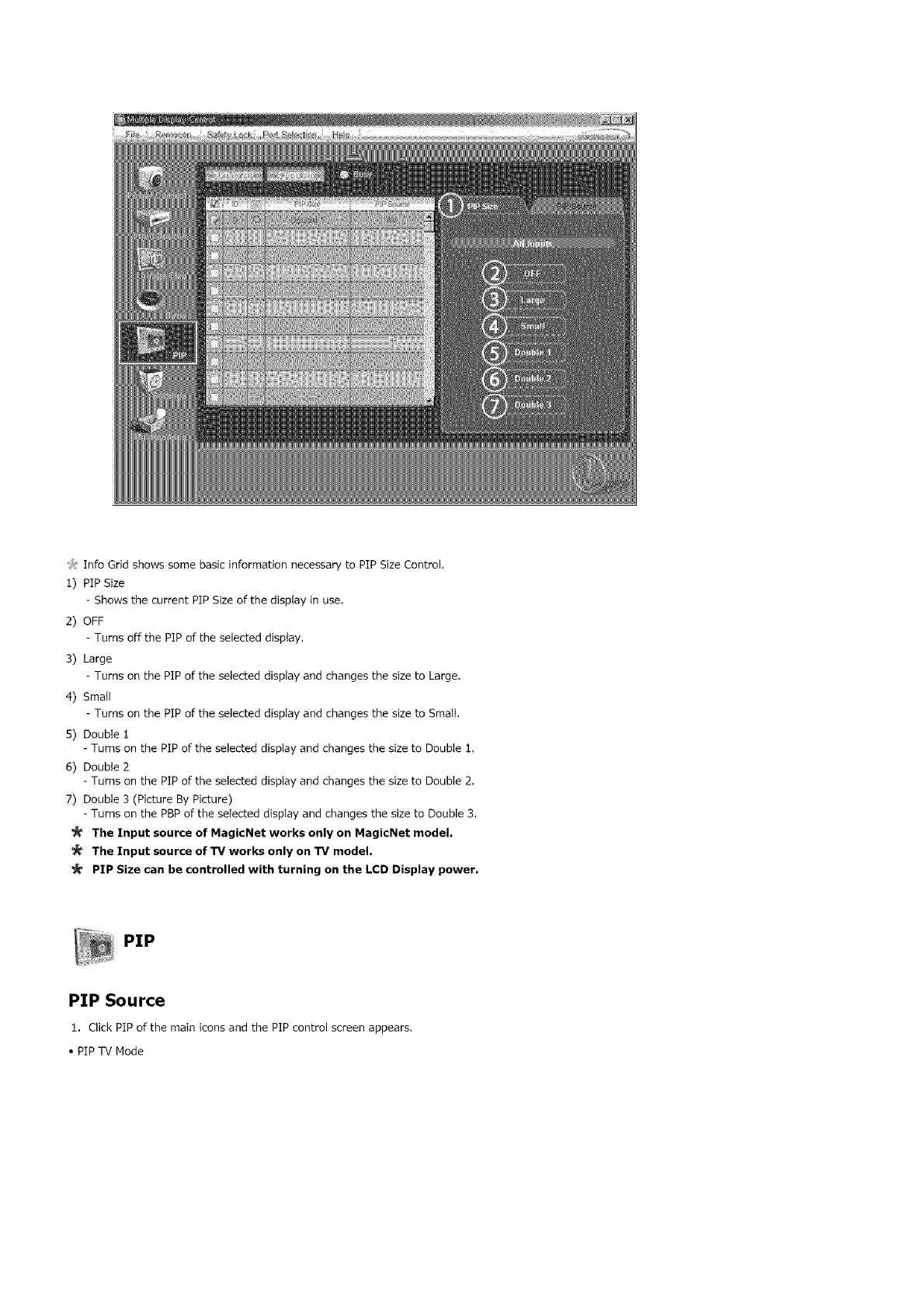
J:InfoGridshowssomebasicinformationnecessarytoPIPSizeControl
1)PIPSize
ShowsthecurrentPIPSizeofthedisplayinuse
2)OFF
TurnsoffthePIPoftheselecteddisptay
3)Large
TurnsonthePIPoftheselecteddispIayandchangesthesizetoLarge
4)SmaIt
-TurnsonthepipoftheselecteddisplayandchangesthesizetoSmall.
5)Doublei
-TurnsonthePIPoftheselecteddisplayandchangesthesizetoDoublei.
6)Double2
-TurnsonthePIPoftheselecteddisplayandchangesthesizetoDouble2.
7)Double3(PictureByPicture)
-TurnsonthePBPoftheselecteddisplayandchangesthesizetoDouble3,
The Input source of MagicNet works only on MagicNet model.
The Input source of TV works only on TV model.
PIP Size can be controlled with turning on the LCD Display power,
PiP
PIP Source
1 Click PiP of the main icons and the PIP control screen appears
• PIP TV Mode
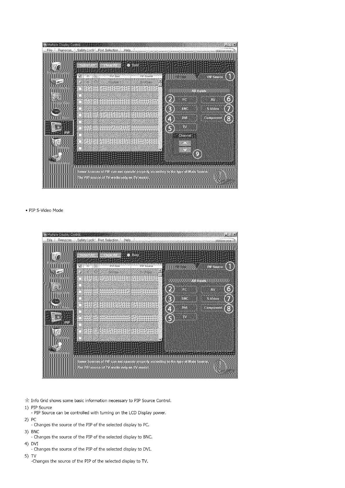
• PiP S-Video Mode
_,: Info Grid shows some basic information necessary to PIP Source Control.
1) PIP Source
- PIP Source can be controlled with turning on the LCD Display power.
2) PC
-Changes thesourceofthePiPoftheselecteddisplaytoPC,
3) BNC
-Changes thesourceofthePiPoftheselecteddisplaytoBNC.
4) DVI
- Changes the source of the PIP of the selected display to DVI.
5) TV
-Changes the source of the PIP of the selected display to TV.
6) AV
- Changes the source of the PlP of the selecteddisplayto AV,
7) S-Video
- Changes the source of the PlP of the selecteddisplayto S-Video,
B) Component
- Changes the source of the PlP of the selecteddisplayto Component,
9) Channel
- Channel arrow appears when the PlP Source isTV,
Note: Some of the PIP Sources may not be available for selectionr depending on the input sourc_ type
of the Main Screen.
The Input source of MagicNet works only on MagicNet model.
The Input source of TV works only on TV model,
TV Source can be selected only in products with TV and controlling channels is allowed only when PIP
Source is TV.
The PIP Control feature is available only for the displays whose power status is ON and the PIP
function is set to ON.
Settings
Picture
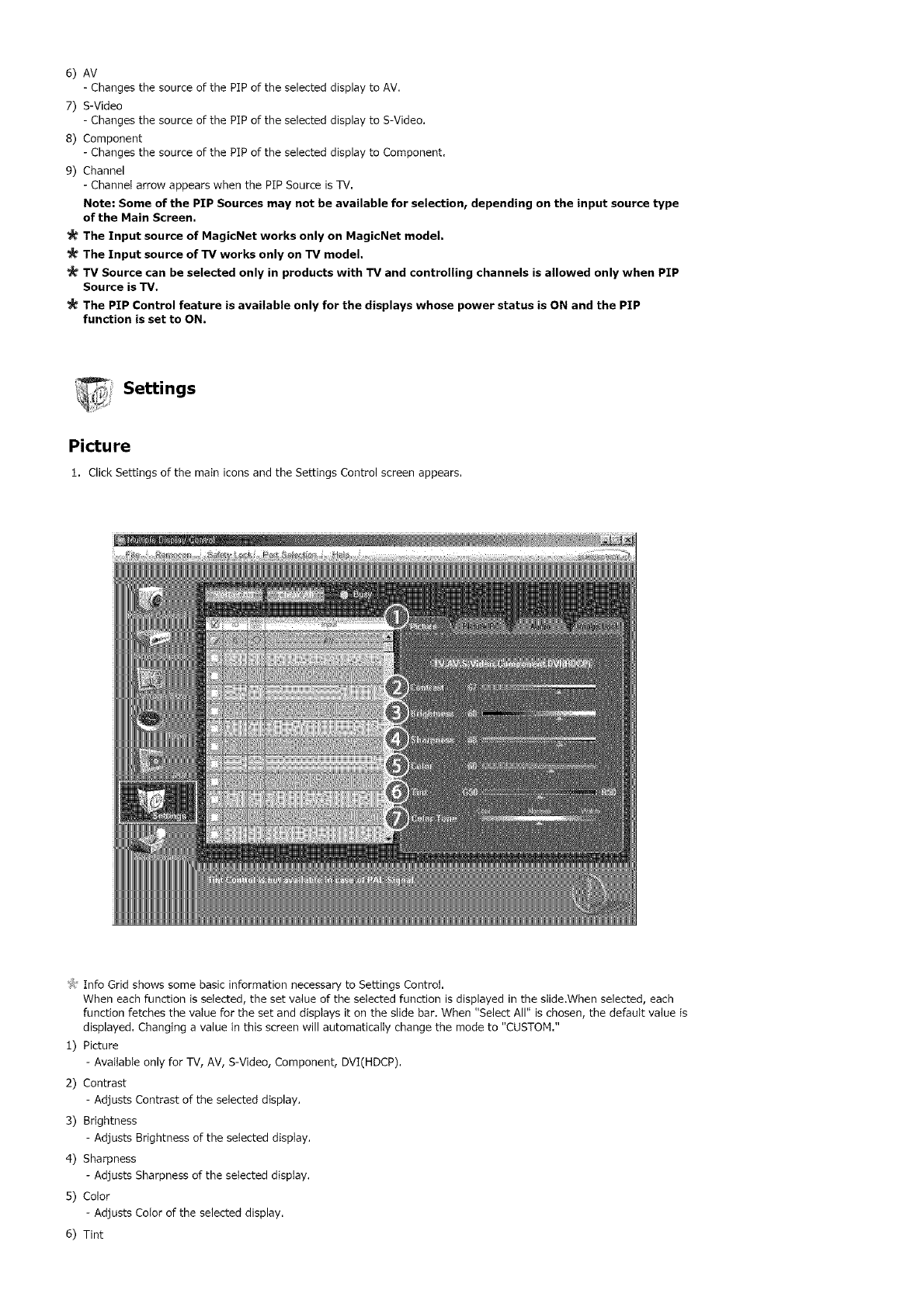
1. Click Settings of the main iconsand the Settings Control screen appears,
_,,:Info Grid shows some basic information necessary to Settings Control.
When each function is selected, the set value of the selected function is displayed in the slide.When selected, each
function fetches the value for the set and displays it on the slide bar. When "Select All" is chosen, the default value is
displayed. Changing a value in this screen will automatically change the mode to "CUSTOM."
1) Picture
- Available only for TV, AV, S-Video, Component, DVI(HDCP).
2) Contrast
- Adjusts Contrast of the selected display.
3) Brightness
- Adjusts Brightness of the selected display.
4) Sharpness
- Adjusts Sharpness of the selected display.
5) Color
- Adjusts Color of the selected display.
6) Tint
-AdjustsTintoftheselecteddisplay.
-AvailableonlyforNT,
7)CotorTone
-AdjuststheColorTonefortheselecteddisplay.
The Input source of MagicNet works only on MagicNet model.
The Input source of TV works only on TV model.
This feature is available only for the displays whose power status is ON and if no selection is made, the
factory default is displayed.
% _ ii
_,_:_ Settings
Picture PC
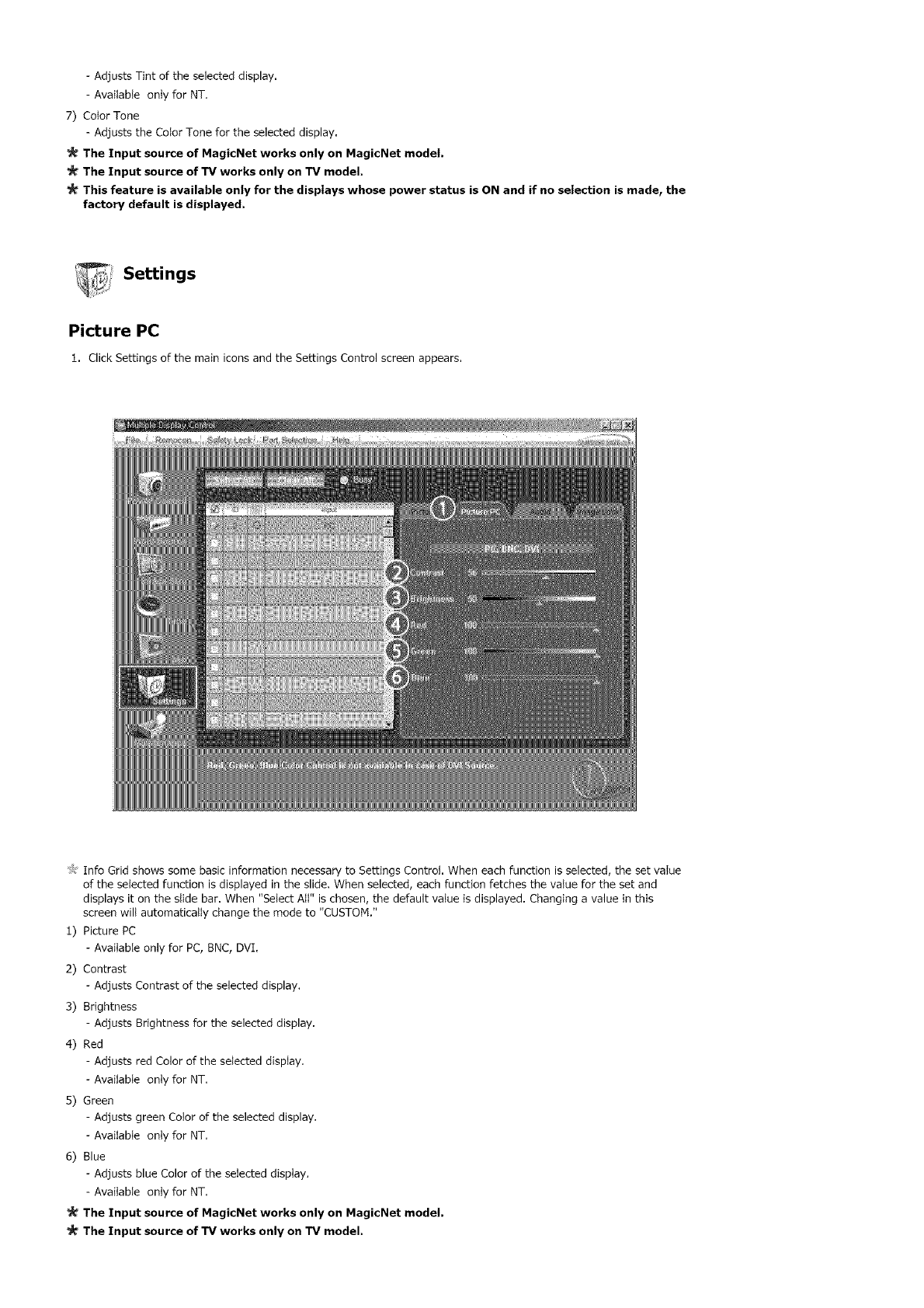
1. Click Settings of the main icons and the Settings Control screen appears.
_): Info Grid shows some basic information necessary to Settings Control. When each function is selected, the set value
of the selected function is displayed in the slide. When selected, each function fetches the value for the set and
displays it on the slide bar. When "Select All" is chosen, the default vatue is displayed. Changing a value in this
screen wilt automatically change the mode to "CUSTOM."
1) Picture PC
- Available only for PC, BNC, DVI.
2) Contrast
- Adjusts Contrast of the selected display.
3) Brightness
- Adjusts Brightness for the selected display.
4) Red
- Adjusts red Color of the selected display.
- Available onty for NT.
5) Green
- Adjusts green Color of the selected display.
- Available onty for NT.
6) Blue
- Adjusts blue Color of the selected display.
- Available only for NT.
The Input source of MagicNet works only on MagicNet model.
The Input source of TV works only on TV model.
_' This feature is available only for the displays whose power status is ON and if no selection is made, the
factory default is displayed.
Settings
Audio
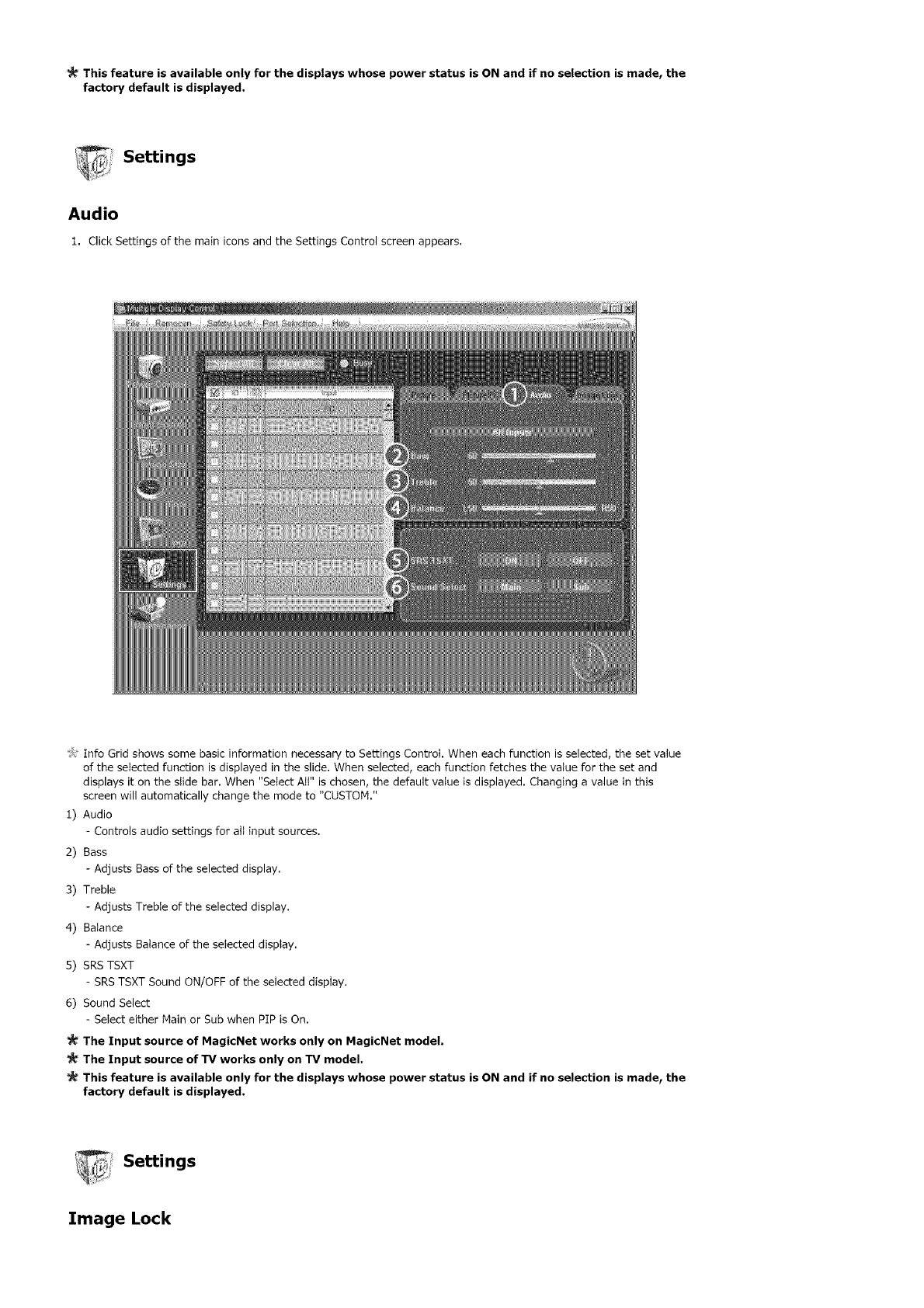
1. Click Settings of the main iconsand the Settings Control screen appears.
_# Info Grid shows some basic information necessary to Settings Control. When each function is selected, the set value
of the selected function is displayed in the slide, When selected, each function fetches the value for the set and
displays it on the slide bar. When "Select Att" is chosen, the default value is displayed. Changing a value in this
screen will automatically change the mode to "CUSTOM."
1) Audio
- Controls audio settings for att input sources,
2) Bass
- Adjusts Bass of the selected display.
3) Treble
- Adjusts Treble of the selected display.
4) Balance
- Adjusts Balance of the selected display,
5) SRSTSXT
- SRSTSXT Sound ON/OFF of the seIected display,
6) Sound Select
-SeIect either Main or Sub when PIP is On.
The Input source of MagicNet works only on MagicNet model.
The Input source of TV works only on TV model.
This feature is available only for the displays whose power status is ON and if no selection is made, the
factory default is displayed.
_Settings
Image Lock
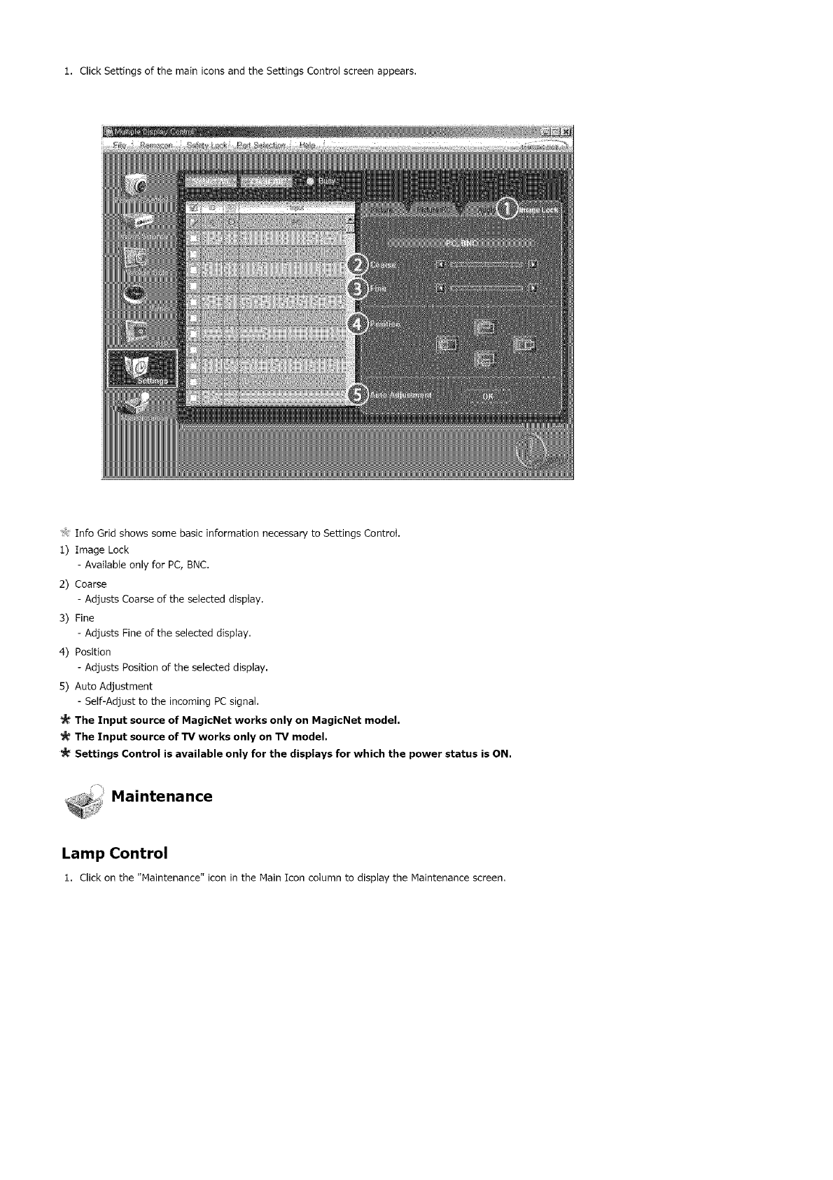
1. Click Settings of the main icons and the Settings Control screen appears,
t_ Info Grid shows some basic information necessary to Settings Control.
1) Image Lock
- AvaitabIe only for PC, BNC.
2) Coarse
- Adjusts Coarse of the selected display.
3) Fine
- Adjusts Fine of the selected display.
4) Position
- Adjusts Position of the selected display.
5) Auto Adjustment
- Self-Adjust to the incoming PCsignal.
The Input source of MagicNet works only on MagicNet model,
The Input source of TV works only on TV model.
Settings Control is available only for the displays for which the power status is ON.
Maintenance
Lamp Control
1. Click on the "Maintenance" icon in the Main Icon cotumn to display the Maintenance screen.
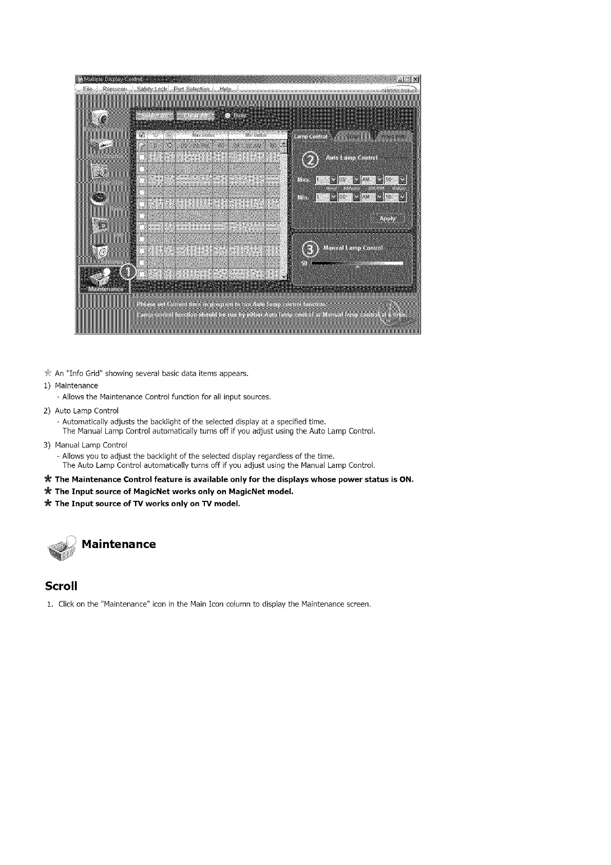
'>:An"InfoGrid"showingseveralbasicdataitemsappears,
1)Maintenance
-AllowstheMaintenanceControlfunctionforallinputsources.
2)AutoLampControl
-Automaticallyadjuststhebacktightoftheselecteddisplayataspecifiedtime.
TheManualLampControlautomaticallyturnsoffifyouadjustusingtheAutoLampControl,
3)ManualLampControl
-Allowsyoutoadjustthebacktightoftheselecteddisplayregardlessofthetime,
TheAutoLampControlautomaticallyturnsoffifyouadjustusingtheManualLampControl.
The Maintenance Control feature is available only for the displays whose power status is ON,
The Input source of MagicNet works only on MagicNet model.
The Input source of TV works only on TV model.
_i_: Maintenance
_iiiiiiiiii_
Scroll
1. Click on the "Maintenance" icon in the Main Icon cotumn to display the Maintenance screen.
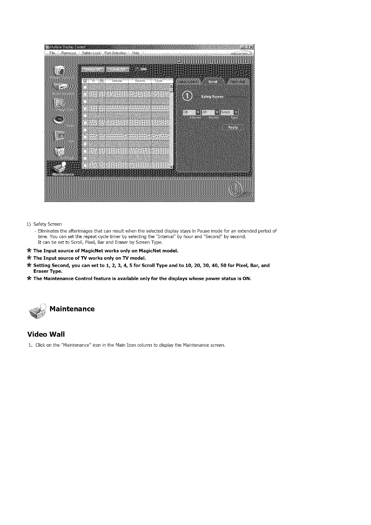
1) Safety Screen
- Eliminates the afterimages that can result when the selected display stays in Pause mode for an extended period of
time, You can set the repeat cycle timer by selecting the "Interval" by hour and "Second" by second,
It can be set to Scroll, Pixel, Bar and Eraser by Screen Type,
The Input source of MagicNet works only on MagicNet model.
The Input source of TV works only on TV model.
Setting Second, you can set to 1, 2, 3, 4, 5 for Scroll Type and to 10, 20, 30, 40, 50 for Pixel, Bar, and
Eraser Type.
The Maintenance Control feature is available only for the displays whose power status is ON.
Maintenance
Video Wall
1. Click on the "Maintenance" icon in the Main Icon column to display the Maintenance screen,
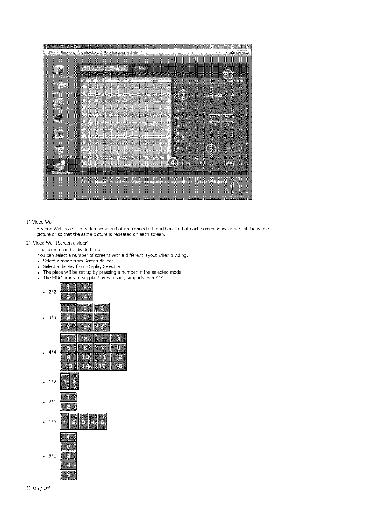
1) Video Watt
- A Video Wall is a set of video screens that are connected together, so that each screen shows a part of the whole
picture or so that the same picture is repeated on each screen.
2) Video Watt (Screen divider)
- The screen can be divided into.
You can select a number of screens with a different layout when dividing.
• Select a mode from Screen divider.
• Select a disptay from Display Selection.
• The place witt be set up by pressing a number in the selected mode.
• The MDC program supptied by Samsung supports over 4"4.
•2*2
• 3*3
•4*4
•1"2
•2"1
• 1"5
•5"1
3) On /Off
- Turns on/off the Video Watt function of the selected display,
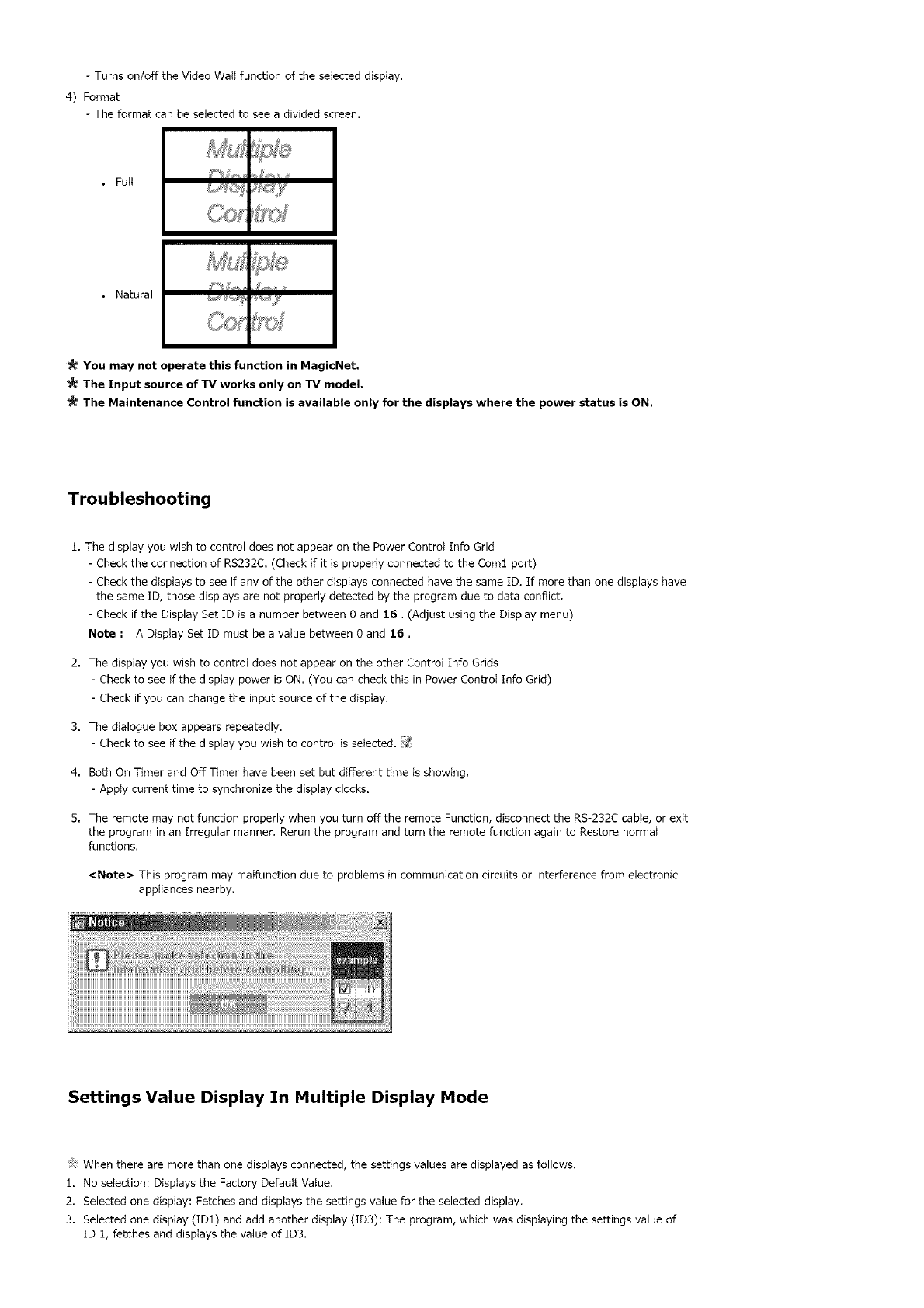
4) Format
- The format can be selected to see a divided screen.
• Full
• Natural
You may not operate this function in MagicNet,
The Input source of TV works only on TV model,
The Maintenance Control function is availabJe only for the displays where the power status is ON.
Troubleshooting
1. The display you wish to control does not appear on the Power Control Info Grid
- Check the connection of RS232C. (Check if it is properly connected to the Coml port)
- Check the displays to see if any of the other displays connected have the same ID. If more than one displays have
the same ID, those displays are not properly detected by the program due to data conflict.
- Check if the Display Set ID is a number between Oand 16. (Adjust using the Display menu)
Note : A Display Set [D must be a value between Oand 16,
2. The display you wish to control does not appear on the other Control Info Grids
- Check to see if the display power is ON. (You can check this in Power ControI Info Grid)
- Check if you can change the input source of the display.
3. The dialogue box appears repeatedly.
- Check to see if the display you wish to control is selected. _
4. Both On Timer and Off Timer have been set but different time is showing.
- Apply current time to synchronize the display clocks.
5. The remote may not function properly when you turn off the remote Function, disconnect the RS-232C cable, or exit
the program in an Irregular manner. Rerun the program and turn the remote function again to Restore normal
functions.
<Note> This program may malfunction due to problems in communication circuits or interference from electronic
appliances nearby.
Settings Value Display In Multiple Display Mode
/!'_When there are more than one displays connected, the settings values are displayed as follows.
1. No selection: Displays the Factory Default Value.
2. Selected one display: Fetches and displays the settings value for the selected display.
3. Selected one display (ID1) and add another display (ID3): The program, which was displaying the settings value of
ID 1, fetches and displays the value of ID3.

4. Selected all sets using Select AIt: Returns to the Factory Default Value,
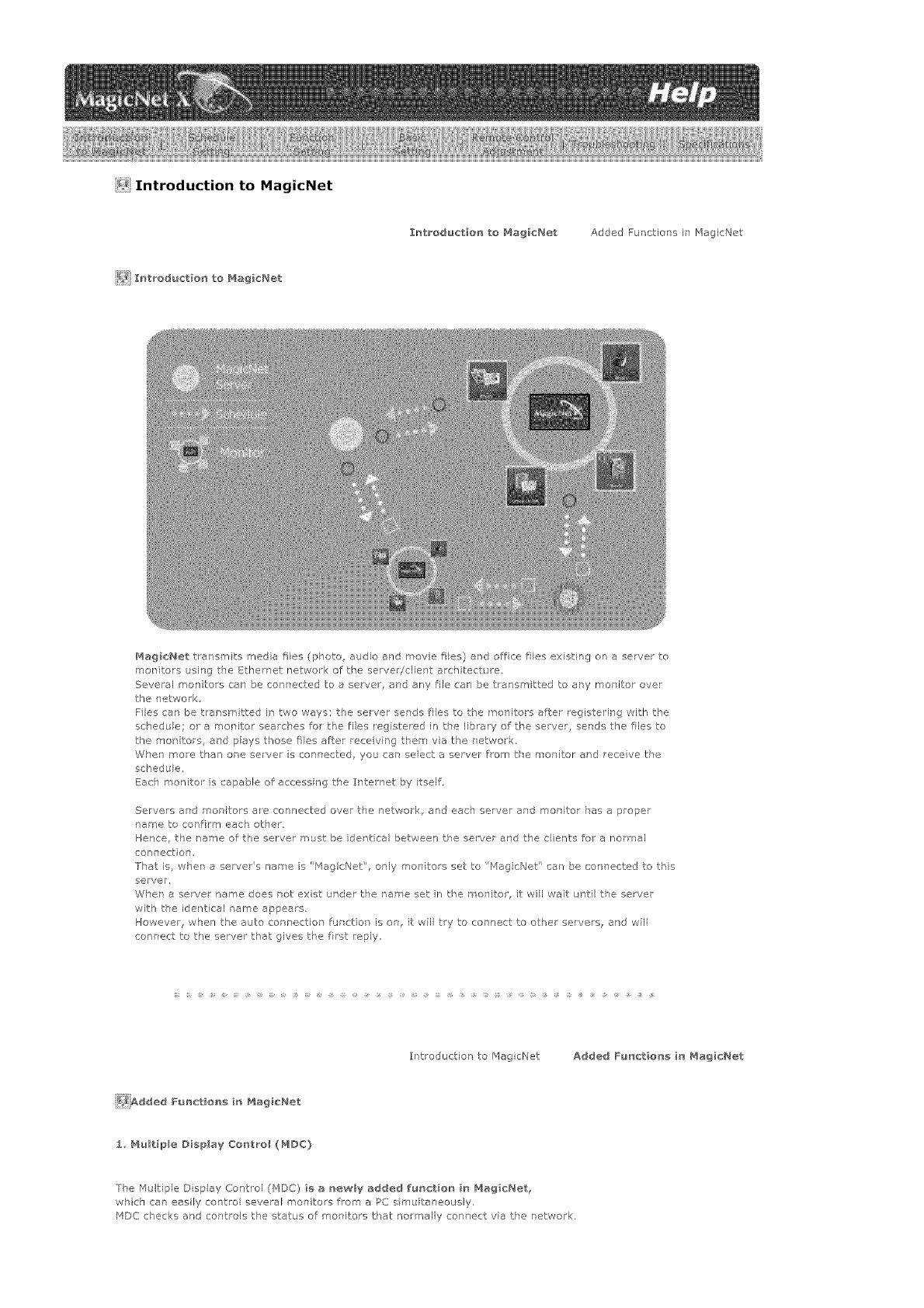
<! Introduction to MagicNet
Introdu6t_o_ to Magicl',_et Added Functions i7 MagicNet
_} Introductler_ to _'_ag_c_,tet
MagicNet transm ts media files (photo audio and movie ties) and off:ca lies ex st ng on a server to
mot ftors using the Ethernet netwo < of the serverJdient archtectue
Several men tots can be connected to a server, and any fie cal _ be transmitted to ary mot itor over
the network
F]es can be transmitted in two ways: the server sends files to the _on tots after registering with the
schedule; or a rnor itor searches for the ties registered in the library of tke server, serds the files to
the monitors, al'd pays t}°ose ties Jter race ving them via the r etwork,
Whet more than ore selver s conr*ected you car, seect a server from the moritor ar'd receive the
schedu e,
Each monito is capable of accessing the Internet by tself.
Servers and mot {tors a_e connected over t_e network, and each server and mot itor has a proper
_ame to cot firm each other,
Hence, the name of the server must be identical between the server and the clients for a normal
con nect on,
]-]at is_ whet a servers name is "[_agicNet', only men tots set to Mag cNet' car be con ]ected to this
server,
Whet a sewer name does not exist under the name set n the monitor, it wil wait until the server
with the ider't cal tame appears,
However, when the auto cot nection furct on is on, it wil try to connect to other servers, and wil
connect to the server that gives tl'e frst reply,
Introduction to r4agicNet Added Functle_ in _4iagicNet
}_iAdded Fu_ction_ _n Mag_cNet
1. Multiple Display Control (MDC)
7he Multiple Disp ay Control (MDC) _ a _te_t{ly added fu_ct_o_ _n Mag_c_et_
wkich can easily control several monitors from a PC s multaneously,
MDC checks and controls the status of monitors that noreal y con 7ect via the network.
2_AccountManage_eHt
Ibisfunctor'prever/tsarandomuserfromfeeyusrgHagicNet,bypbdngirritsontheapeationof
functiorsaccordngtotheaccountprivlege,
3_ Update
You ca!" update a monitors MagicNet from the servel,
However, ths function oral,! works _'her it is connected to a sever!monitor with HaglcNet Ve_ 20 or hg]e,
For Sync_laster 320PXn!400P(T]Xn!460PXn, see Add!Remove Programs.
4, Controlling Loca_ Storage Dev_cesiUSB F_le Co_tro_ of Monitors
You can copy or delete files to a mentors local stoage device el via USB connected to tie monitor,
5_ Schedule Pause
This functior pauses tie ergo rg sckedule in the morite ,and is useful in tke event of urgent y needir g to
conduct other wo<.
Press the buttors n the oder of [+IO0]-[8]-[2]-[4]-[[NTER] or tie monito wtk the emote controt,and
the schedule will pause tempo arily,
To resume the tenlporalily paused schedule, press the buttol s in the odel of [PRB-CH]-[8]-[2]-[4] o
[ENTER]orl the rerrote contro ,
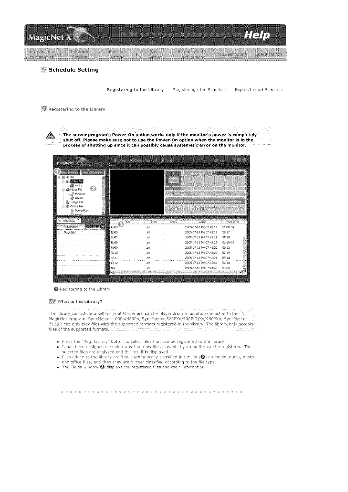
i_i Schedule Setting
Registering to the L_brary P,egistering /the Schedule Export/Import Schedule
i_ Aegistering to the L_brary
The server program's Power_On option works Only if the monitor's power is Completely
shut off_ Please make sure not to use the Power,On option when the monitor is in the
process of shutting up since it can possibly cause systemetic error on the monitor.
0 Reg stering to the L brary
_Y_ What is the Library?
The b arY Cons Sts o_ a Co leCt on of ties which ca_'_be payed from a monite connected to the
l'4agicNet P Og ar9. Syn Haster 400Pn/460P , SyncMaster 320px /400P(T}Xn/460PXn, Syncf4aster
71!ND can ony play lies wi_h tbe supported formats reg stered n the ibrary, rhe !ibrary ony a ePt
fies of the suppo:ted [ormats=
Press the "Reg Libraw" button to select ties t_at can be registered to the library,
:['chas been designed in such a way tPat only flies p ayab e by e monitor can be registered, The
elected ties are analyzed and the result is d splayed.
Flies added to the library are first, automatical y classified in the list (0) as movie, audo, photo
ard offce lies, and then they are furt,ker e essified according to the file type
The Fields window(_}disp ays the registered ties ard their informatior,
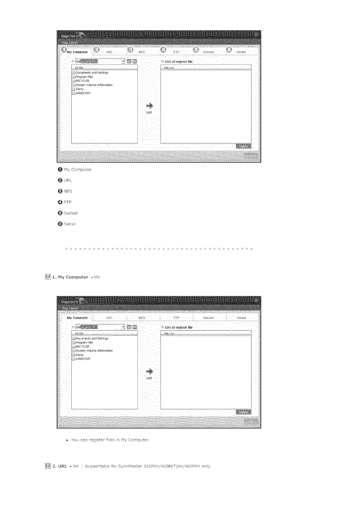
0 HyComputer
URL
NFS
QFTP
Socket
Serial
_ 1_ My Com_uter
You can register files r Hy Computer
_ 2 URL : Supportable for SyncHaster 320PXn/400P(T)Xn/460PXn only
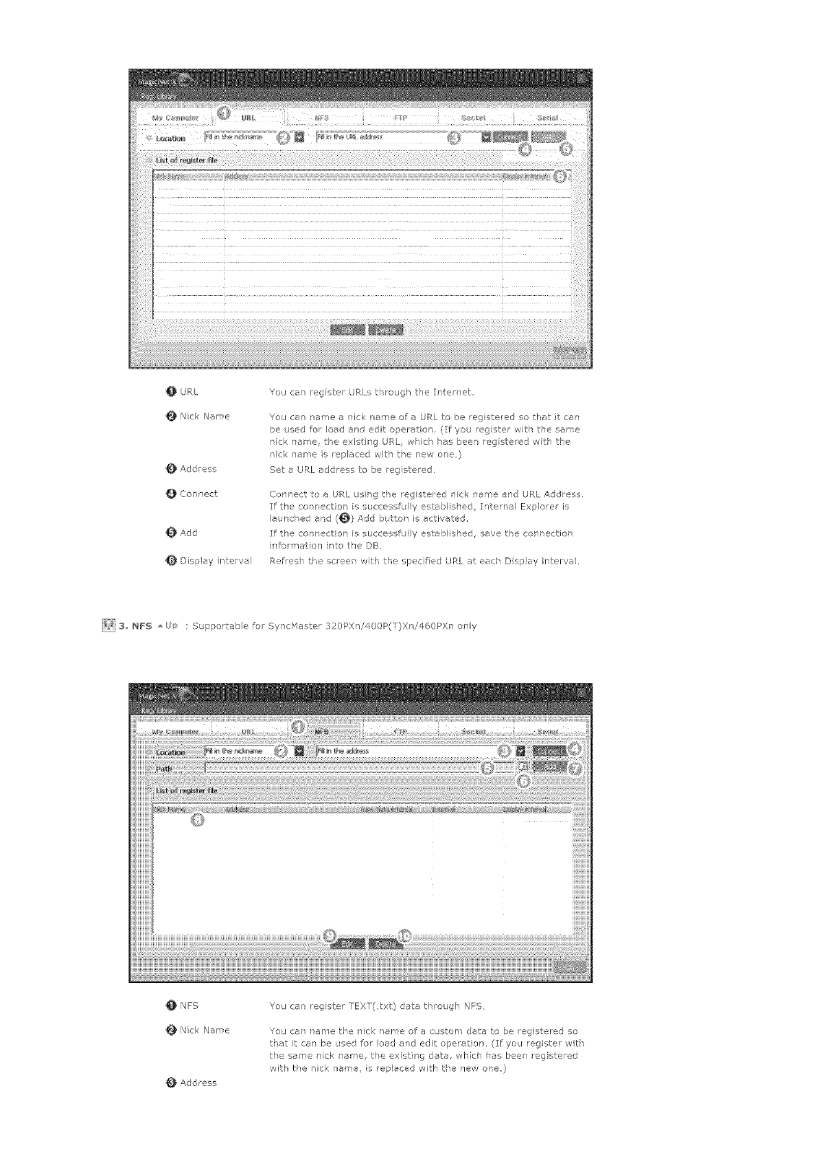
OURL
NickName
Addtess
QConnect
Add
Dfsplaynterval
YoucanregsterURLsth/eughtieIntemet
YoucannameanicknameoreURLtobelegisteredsothatitcap
beusedforloadandeditoperation(Ifyouregisterv,/ith the same
_]ick name, t_e existing URL, w]lch ,_es been reg stewed wth the
nfc name s replaced witk the new one}
Set e URL address to be registe ed.
Connect to a URL usrg t,_e registered _Tick name and URL Address.
If the cot nection is st_ccessfu ly estabis]ed Internal _!xplore_ s
leuncV ed and (_) Add bJtton is activate(,
If the connection is successfully established, save the conr ecUor
information nto the DB,
Ref esh the screen wth the spedf ed URI. at each Disp ay interva .
_ 3 NFS : Supportable for SyncMaster 320PXni400P(T)Xn/460PXn only
NFS
Nick Name
Add tess
You can reg ster TEXT(_txt} data t,_rough NFS,
You can tame the nick name of a custom data to be registered so
that tca] be used for load and edit operation, (If you registe_ vvth
the same rTck name, tke existing data, whirl" has been egistered
with the nick name, is rep eced with the new one,)
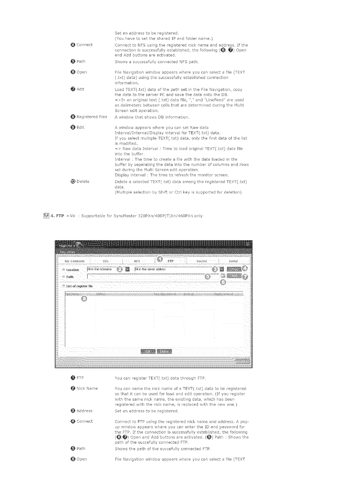
Connect
O Path
Q Open
O Add
Rag stered flies
E@t
@_ Delete
Set an address to be rag stered,
(You have to set the shared IP and foder name,)
Con ]ect to NFS using tfe registered nick name and address, If t,_e
connectior is successfully esteblisVed, tie forlewing (_, _) Open
and Add buttons are activated
Shews a successfully conrected NFS pet],
File Navigation window appears where you can select a file (TEXT
(txt) date) using the successfu ly estab ished connect on
info_'matien,
Load TEXT(txt) data of the pet] set in t,_e Fie Navigation, copy
the data to the server PC aid save the data or'to the DB.
=>It an original text (.txt) data fie ",' and 'LineFeed' e_e used
as delimeters between cels tVat are determined durPg t_e Multi
Screen edt operation,
A wi]dow that shows DB [nformat or
A windew appears whee you car set Raw data
IntervaI/ITtervayDisplay nterval for TEXT(,txt) data
If you seect multiple TEXT(,txt) data, ony the frst data of t,_e list
is modified,
=> Raw data Irterve : Time to eed o gral TEXT(,txt) data fie
i_to tie buffer.
Interval : The tir<e to create a fie wtb the care loaded in the
buffer by separating the data rto the nun bet of columr s and rows
set durir'g the Mult Scree] edit opetatiom
Display rtervel : The tree to refresh tie molitor screen,
Delete a selected TEXT(.txt) data among the registered TEXT(,txt)
data,
(Multiple selection by Shift: or Ctrl key s supported fo deletion)
_2/i 4,, FYP : Supportable for SyncMaste< 320PX ]i400P(T)Xn/460PXn only
FTP
Nick Name
Add tess
Cor'nect
Path
Open
You can rag ster TEXT(,txt) data threugh FTP,
You car/ tame tfe rick name of e TEXT(,txt) data to be registered
so that it can be used for load and edit operation (:If you register
with the saree nick name, the exst rg data, whch has been
rag stared with the nick name, s replaced with the new ore.)
Set an address to be rag stered.
Connect to FTP usirg the registered nick name erd address, A pop
up wrdow appears w['ere you can ante the ID and password for
the FTP, If the cent ection is successfully established, the follewing
(_) Open ar, d Add butto]s are act vated (_) Pet) : Shows tie
path of tVe succefu ly connected FTP,
Shews the path of the succefully connected FTP.
File Navigation window appeals where yo_ can select a file (TEXT
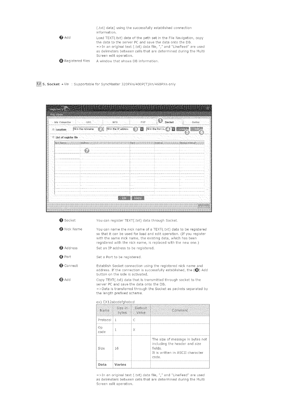
Add
Rag stared fles
(txt) date} using the successfu ly estab ished connection
information.
Load TEXT(,txt) data of the path set in the Fie Navigation, copy
the data to the servel PC and save the data onto the DB,
=>It an original text (,txt) data fl% '/ and ' LineFeed' a_e used
as de/imete_s between cells that are determined duri]g the r_ulti
Screen edt operation.
A whsdow that shows DB informet on,
_7_ B, Socket : Supportab e for SyncfV_aster 320PXri400P(T)Xni460PX only
_Socket
_Nick Name
_Address
_Port
Connect
_Add
Yos can rag ster TEXT(.txt) data through Socket,
You can ,name the nick name ore TEXT(,txt) data to be registered
so that it can be used for load and edit operation (_ff you register
wits the same nick tame, the ex st ng data, wsch has beer
rag stered with the nick name, s replaced with the new one.)
Set an IP address to be registered.
Set a Port to be reg steled.
Establish Socket connectior using the registered nck nare and
address, If the connect on s successfully establ shed, the (_} Add
b_ttor on the side is act rated.
Copy FEXT(.txt) data that is tre_smitted through socket to the
server PC and save the data onto the DB
=,_Dete is transferred thro igk the Socket as packets separated by
the lergth prefixed scheme.
ex) CX12abcdefgk abcd
Protocol 1 i C
i iX
i The sze of message in bytes rot
i including t_e header and sze
Sze 16 fieds,
It is w itten in ASCII character
code,
Data Var_e5
=>It an original text (,txt) data fie, "/' and "LineFeed" are used
as delirneters between cells that are determ ned during the Multi
Screen edt operation,
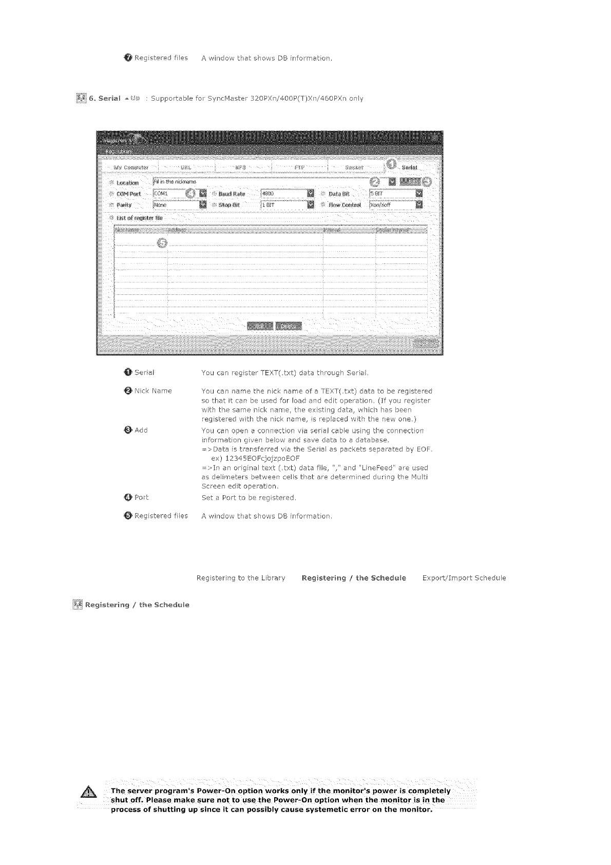
Registeredlies AwirdowthatshowsDBinformeror,
_ 6,Serial : Supportablefo Sync_4aster320PXi400P(T)X]/460PXronly
Serial
Nk:kName
_}Add
OPort
Regsteredfiles
YoucanregsterTEXT(,txt}datathroughSerial
Youcar/namethericknameofaTEXT(,txt)datatoberegistered
sothatitcanbeusedforloadandeditoperation(Ifyo_register
withthesamerick tame, the ex st rg data, w]ch has been
rag stewed with the nick name, s replaced with the new one.)
You can open _ connection va serial cable L;sing the connection
bformatior given below end save date to a database.
;;;;>Data is rensferred via the Serial as packets separated by EQF
ex) _2345EOF(]ojzpoEQF
=>It ar original text (,txt) data fie '," erd "LineFeed' ere used
as delimeters between cells that are determined dud]g the Multi
Screen edt ope ation,
Set e Port to be reg stered,
A window that shows DB informer on,
Registering to the Librar
[_ Reg_sterb_g /the Schedule
Registering /the S¢hed_le Export/Import Schedule
The server program!s Power_On option works only if the monitorls power is Completely
shut off_ Please make sure not to use the P0wer_on option when the monitor is in the
process of shutting up since it Can possibly cause systemetic error on the monitor.
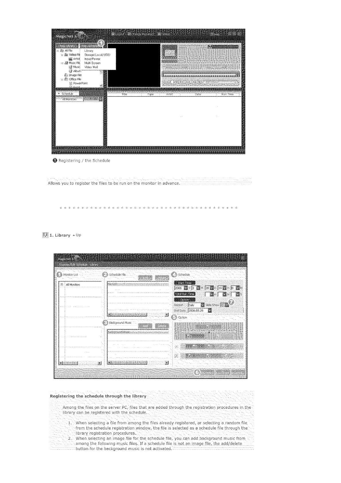
0 Reg stering/theSchedtde
Alows you to regbter the fle_ to be run on the mon tot in advance.
_[IIol)_ the tles oll _rle serve PC. _ eS ERrOr 7#['e1ClUeS trlHot gM tl ='reg SL a Io -I O_oceoo[ :_ "Itfe
i. _ner/ se ec[Inc _ fie from amor!g the flies a reaay _eg s<e_;@ s se_ec[lr g s ranoom Tile
ro_ [hc _chedtile r_glSL_lOfl WIn_OW_ <he _ile IS %e_ecie_ _s _ sc_eQ_le /_le_ ul_otlgl L_e
2, Wh_r_ s_ _(/{ _ _ _[ft_c _ fi_e _ the schedule tile yo_ c1_ al_<_ o_ CKg_O_nQ INUSIt MO_
_mon_ :be to_lowin _ n sic [iles. ]_ _ _l e<xu_e fi_e s no_ _n rr!a_ ? fl_ _ne _o< Qele_e
_}uI1_o_%_o_ the b_ckg_ouP_o i_us_< Is i%o[ _c_lva_eG.
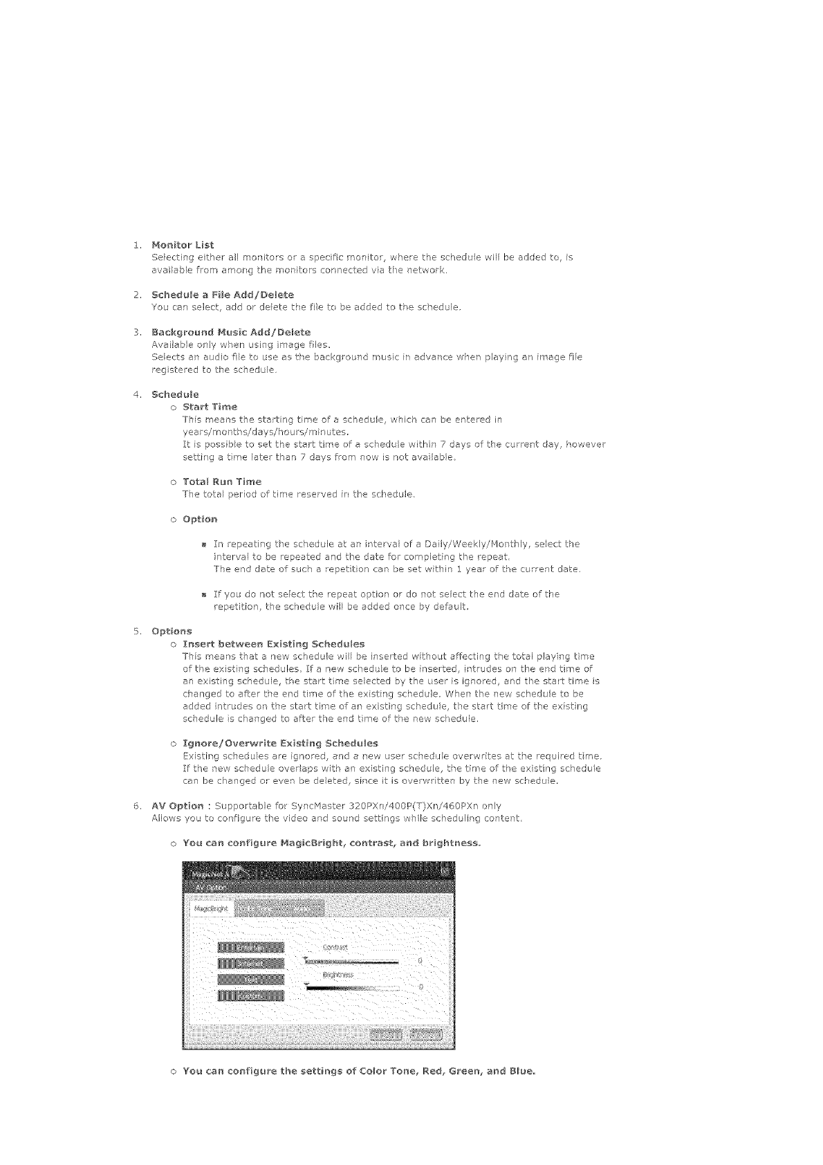
2, Monitor List
Selecting either all monitors or a spedfc monitor where the schedu e will be added to is
avai able from amorg the monitors connected va tie ]etwork,
2, Schedule a Fi_e Add/Delete
You car select, add or delete t,_e fie to be added to tPe schedule,
3, Background Hus_c Add/De_ete
Available only when using image fles
Selects an audio fie to use as tPe background music in advance w]en playing an image fie
reg stered to the scsedule.
4, Schedule
n Start Time
Ths means the starting time of a schedule, which can be entered in
years/mor tV s/ days/houl s/minutes,
It s poss b e to set the start time of a schedule withr 7 days of the curre ]t day, however
setting a tree late/than 7 days from now is not ave labia
o Total Run Time
The tote period of time reserved in the schedule
nOption}
In repeati]g tle schedule at an r terval of a Daily/Weekly/Monthly, select tle
i]tervaf to be repeated and the date for completing the _epeat,
The end date of suc] a repet tk_n can be set within 1 year of t,_e current date
If you do not select the repeat option or do not select the end date of the
repetition, the schedule will be added o]ce by default,
5, Opt_on_
o Insert between E×_t_ng Schedule5
rhs means t_at a new schedule will be inserted without af_ecting the total paying time
of the existing schedules, If a new schedu e to be inserted, int_udes on the and time off
an existing schedule, tl'e start tree selected by the user is ignored, and tl'e start time is
d'ar'gec to after the er'd th'ne of the ex st rg schedule When the new sd'edu e to be
added intrudes or the start time of ar existing schedu e, the start time of the ex st ng
schedule s clanged to after the end time of the new schedule.
Ignore!Overwr_te Existing Sched_e5
Existing sc}'edu es are ignored, and a new user schedu e overw/ites at the reqL ired tree,
If the new schedule over aps witV an existing schedule, the time of t,_e existing schedule
can be clanged or ever be deleted, sirce it is overwritten by the new sckedule,
6. AV Option : Suppor able for SyncHaster 320PXni400P(T}Xn!460PXr only
Allows you to cot figure the video ard sound settings whle schedul r g content
n You car_ configure NagicBr[ght_ cnntra_t_ and brightness,,
o You car_ configure the settings of Co,or To_e_ Red_ Green, and Blue,,
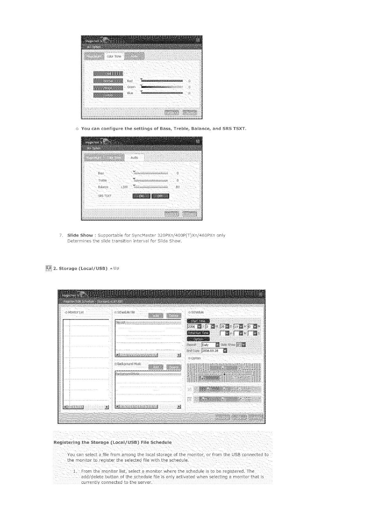
oYoa can co_figu_e the settings of Ia_s Treble galar_ce= a_d SRI "[%XT=
7. SHale Show : Supportable for SyncHaster 320PXn/400P(T)Xn/460PXn ony
Determines the side tran itio_ nterval fo Side Show.
_'_i}2, Storage (LocallUSI) =,
Yo ca_ select a file frm among the local storage of the monitoG or from the USB connected to
•From the monitor st select a mo_sitor where the sched<Ae i5 0 be egistered, The
add/de ere button of £he sched_J e fi!e s 00Y act yated whe n e ectisg a mor/to ha S
cuiTent y coaRected to the server'.
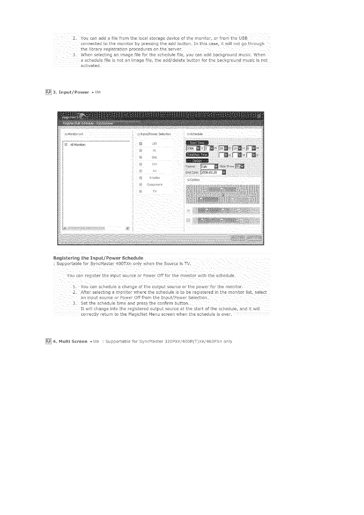
z
2 You _7an add a fie from the Iota storage device of the montr r from the USB
con ectedtothe son or by _ressing th_ add butt_rb In t s ase itw _not go through
the brary reg straUop rocedures on the server.
3, When select ng an sage file fcr the scbedu a fie, you can add background rn _sic_ When
a schedule fie s !)ot an sage f!e_ he add/de!ere button _cr the background mast s not
activated.
_i3 I_put/Power
1: You can schedu e a change of the output source or the power for the _on to .
2. Afte selecting a montor whe e he s_hedu e s t O be rag stered in the rnon to it, select
an nput source 9r Power Off fl'om the putl_war Selection
3. Set the schedu e time and press the conf rm button
lit wl change into the registered outp 1<so< rce at the start of the sched_x e, andt wi!
co rectly retu rl to the Hag cNet Henu screen when the schedule s over.
_,{ 4 _ t 56reee _ : Supportable fo Sync:Haster 320PXn/400P(T)Xn/460PXn oily
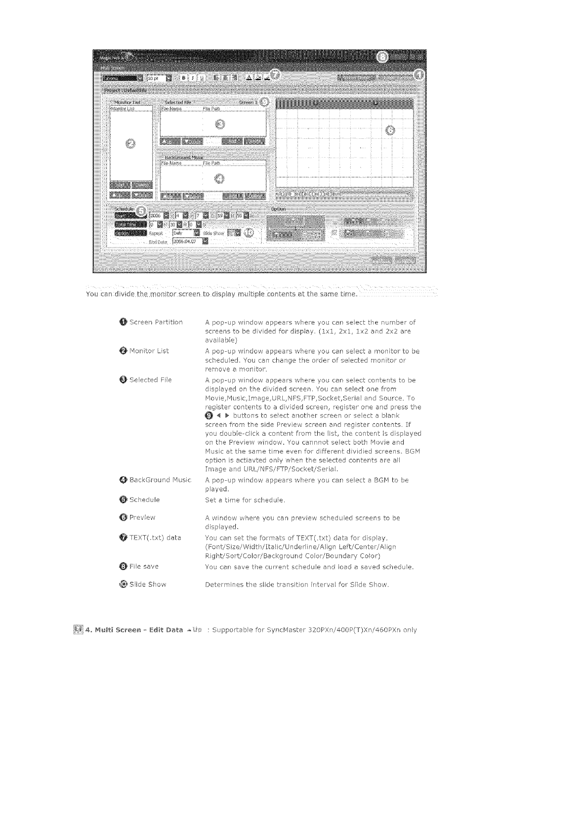
_i!!!ii_,_ ¸¸_}iii iiiiiiiil?iiiili!i!{iiii!iii!iiiilii¸i!iiiii{i¸iiii_iiiiiii!iii!!iiii!ilii(iii_i!£ i
You can dvde the mort tot scene to dispJay mu £ pie conRents at the same time
Screen Partition
_4on for List
Selected File
_BackGround /'ausic
_Schedule
_Preview
_TEXT(,txt) data
File save
Slide Show
A pop-up window appears w_ere you can select the numbe of
screer's to be divided for display (lxl, 2xl :1x2 ard 2x2 are
avai ab e)
A pop--up window appea!s w]ere you can select a monitor to be
schedu ed, You can change the order of se ected monitor or
remove a monitor,
A papup wiTdow appears where yob car select contents to be
displayed on the div dad screen, You can seect ore from
Movie,P4 _sic,Image,URL, NFS,FTP,Socket,Seria ard Source, To
rag ster contents to a divided screen, register one and press the
_ _ buttons to select another screen al seecta blank
screen from the sde Prey ew screen ard reg ster contents, If
you daub e-dick a content from the list, t}°e cow-tent is displayed
on the Prev ew wndow You cannnot select botch Movie and
blusic at tie same time even for d ffere]t dividied screeas, BGr'a
option is acUavted orly when the selected contents are all
Image and URL!NFS/FTP/SocketiSeria,
A pop-- tp window appears where you can select a BGP4 to be
played
Set a time for schedule.
A window where you can preview scheduled screens to be
displayed
You car set tPe fo_'mats of T_!XT(,txt} data for d splay
(Fo Tt!Size/Width/Ita ic/Unded}ne/AI g ] Le_t!Center/A igr
Right/Sort/Colo//Background Color/Boundary Colo/)
You car save the current schedule and load a saved schedule.
Determines the side tral'sitio] in,.erval fo Side Show.
_]}}i4,, _ulti Sc_ee_ o Edit Data ,o : S _pportable for Syncblaster 320PXni400P(T)Xni460PXn erly
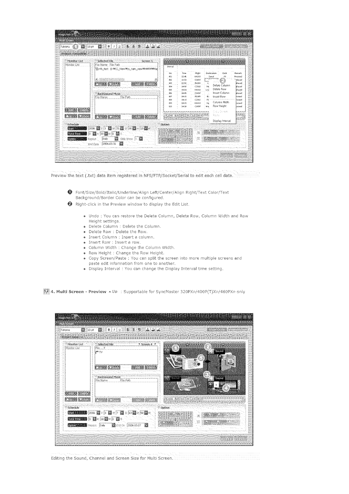
iiiiiiiii
iiiiiiiil
iiiiiiiil
iiiiiiiil
iiiiiiiil
iiiiiiiil
iiiiiiiil
iiiiiiiil
iiiiiiiil
iiiiiiiil
iiiiiiiil
iiiiiiiil
iiiiiiiil
iiiiiiii!
iiiiiiiil
iiiiiiii!,
Preview the text (;t×t) date item rag sterrad io _,JFS!ETPlSocket!Seria to edt each cell date,
Fon,.iSize/_/Bad//Italfc,/Undedin e_/Align Left/Center/AI g 1 Right!Text Color/Text
Backgroued!Border Color can be configured,
Right-cl ck in the Prey ew wndow to dspey the Edit List,
Undo : You can restoe the Delete Co umn, Delete Row, Column Wdth end Row
Height settings,
e Daete Columr : Delete the Columr,
Deete Row : Delete the P,ow,
I ]aet Column : Insert a column,
Insert Pew ; Insert e row,
Column Wdth ; Change the Column Width,
Row Height : C]ange the Row Height,
Copy Screer !Paste ; You can split the acleen bite reore multiple screers erd
paste edt nformatlor from ore to another,
D splay Interval : You can charge the Dspay Interval tirne setti ]g,
_i_ 4,, M_lti 5cree_ _ Prev}ew : Supper able re Sy ]cr_laster 320PXr !400P(T)Xr !460PXn any
Editingthe Sound, Channel end Screen Sze for Muti Screen.
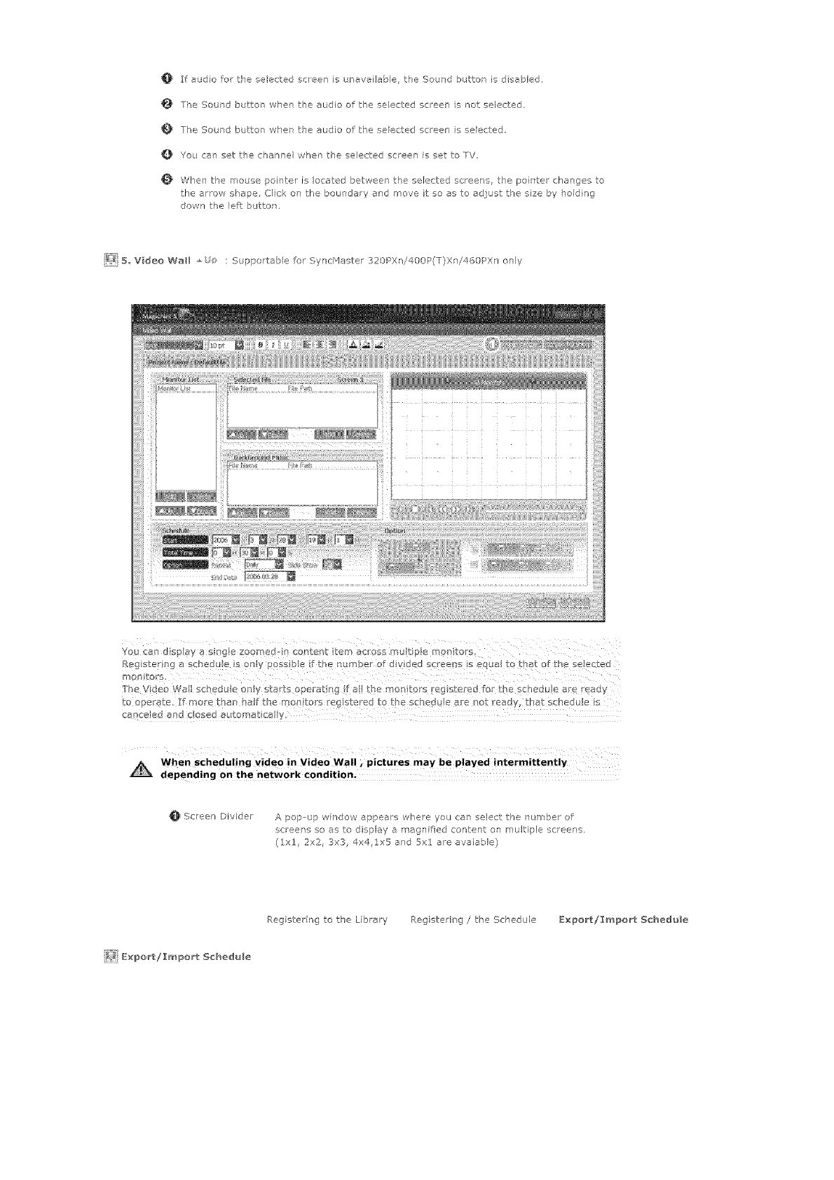
O If audio for the selected scleen is uraveiabe the Sound button is d sabled.
TPe Sourd buttor whet the audio of the se_ed:ed sceen s not selected
The Saurd buttor when the audio of the seected screer" s selected,
Q You can set the channel when tl'e selected sceen is set to TV
When the mouse pointer is _ocated between the selected screens, the poirff;el changes to
the arrow shape Clck on the boundary end move it so as to adjust the size by hodng
down the left button.
_{_ 5, Video Wall : Suppotab e for SyncHaster 320PXn/400P(T)Xni460PXn only
Register nga sched _e s only possible f the number of d vided s<ree[_s s {._qual to that of the selected
man}tars.
e e
Th. VdeaWa schedLeonystaH_ope/:atng fa!themar_torsreg_telledfortbeSCheduea_e cady
When scheduling video i nVideo Wall _pictures may be played intermittently
depending on the network Condition;
Screen Dfvider A pop-up window appears w]e;e you can select the number of
screens so as to display a magn fled content o] multiple screer s.
(lxl, 2x2, 3x3 4x4,1x5 and 5xl are avaiable)
Register ng to the Library RegisteriTg /the Schedule E×po_t!I_port Schedule
_ E×po_/_port Schedule
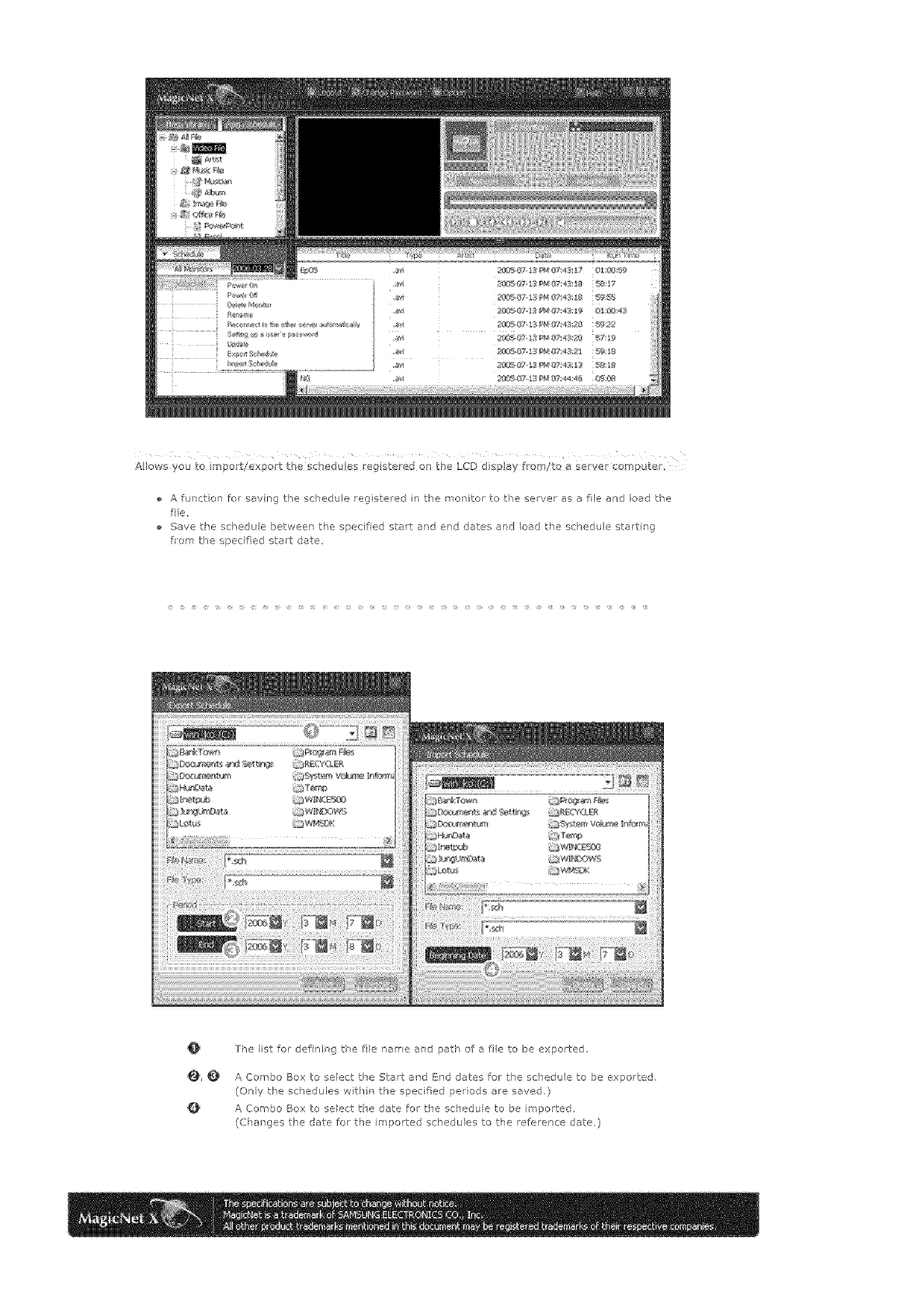
Allowsyouo report/exportthescheduesr gisteredantheLCDdsplayfmmltoaservercomputer,
Afurctonforsavingthescheduleregisteredinthemonitortotheserverasafileandoadthe
file,
Savetheschedulebetweenthespedfadstartandenddatesandloadtheschedulestarting
forethespecifiedstartdate
@
@,¢
o
The list for defin ng tke file name and path of a fie to be exported
A Co _]bo Box to select the SLat and End dates for the schedule to be exparted,
(Ony the schedules wit]n the specified periods are saved,}
A Combo Box to select the date for the schedule to be imported,
(C_anges the date for the imported scl'edules to the reference date 0
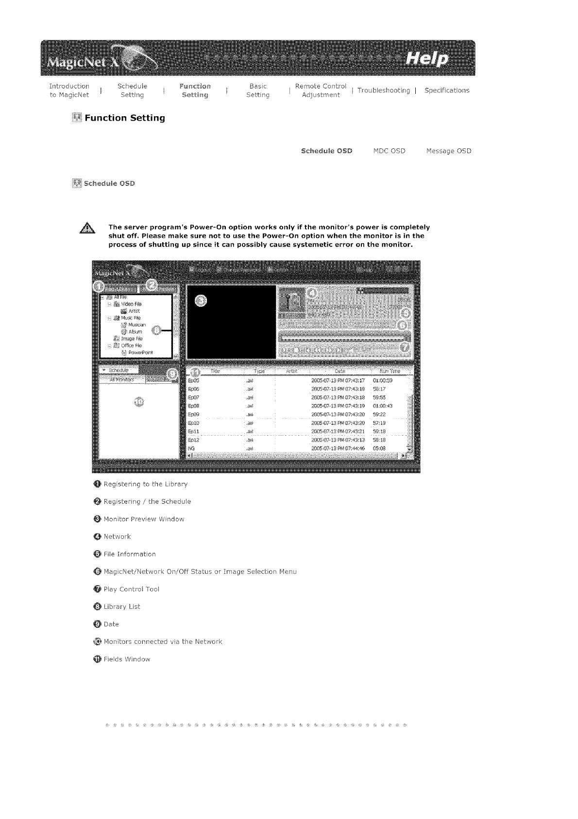
Introduction Schedule Fu_tio_t Baec RemoteContro
I I I
to IqagicNet Setting 5e_t b_g Setting Adjustment
_Function Setting
_{_ Schedule OSD
Troubleshooting I Specifications
Schedule OSD HDC OSD Message OSD
The Power-On works if the monitor's is
server program's option only power comp|ete|y
shut off, Please make sure not to use the Power-On option when the monitor is in the
process of shutting up since it can possibly cause systemetic error on the monitor.
0 Reg ster ng to the L brary
Register ng/ the Schedule
kionito_ Preview Window
Network
Fie Informer on
rqagicNet!Netwo_k On!Off Status or [Image Se ection Henu
PIa,/ Control Tool
Library List
Date
Iqonito_'s connected via the Network
Fields Window
OMonitorPreviewWi]dow
Thiswindowisusedethertopreviewafie(amoveorphotofile)regsteredinthelibraryist(_)and
selectednthefeldswndow(_),ortomontotamorqtor.
P_ayir_gafilereg_gtered_ thelibrary
ClickonacassificationintielibraryIst(O),andtheflies*.lndertTeselectedcassficationare
dspayedinthefieldswindow(_) The],double--cickonafieintiefieldswindowtopayit.
Whilepaying,tiefieinformationisdisplayedin0 Onlyaudiomove,andmagefliescanbe
payedForofficeties,orb/fileinformatopisdisplayedin_, Rowever,f morttoringfora
morqtorisproceedng,theinformationbengmo]itoredisdsplayedinstead,
Mo_ori_gthe5electedmon_to_(Preview}
Withthereleva_tmonitorselectedbyanumber_._(the-Tameoft-remonitorw[ bedsplayed
inthefield_), thescreenplayedbythecurrently-selectedmonitorwillbedisplayed.
Audo,vdeoandimagefilescanbepayed,whileoilythefileirlformatorappearsforoffice
ties.
(nthscaseorlyfilesregbteredinthe I brary of the server will be played, and the Iocal/USB
ties on the morqtor w/I d splay only the basic information Ir addition, when the output source
of a monitor does not belong to _qagicNet, informatior" on the relevar t output source will be
disp ayed )
For Multi Screen and Video Wall, the filename of the project beirg payed bad< is displayed,
Netwo k _ _,
The status bar next to the monitor name will display the overall netwo k status (traffic) of al tie
monitors connected to the serve_ Fo examp e assume that: the network system capab Iity is lO0_qbs
and a lOOMbs ]etwork card is installed n tie server, If there s rio networ traffc used for other
purposes, thee mo ]itors ate con ]eeted, ard each monitor uses lO_,1bs of traffic, the prog ession will
be rd cared as about 30%.
A Server PC Environmerlt: Reeomrnerded (CPL: 3GHz, RAM:Sl2M, Ethernet:
100M/_¢)
Network Environment: Local netwo k not connected externa ly
- Norma : Server PC network bandw dth: 50% _ 60%
.r'aax: Server PC network ba ]d,Mdth: 90% or more (not _'ecommended)
For a LAfq--eonnected env for ment, tfe connectable number of dev ces may
be reduced depending on the availability of neighboring networks,
Fie Information _u/s
This wil display the name, date, size and resolut on of the curre it fie,
MagicHet!Netwo/k On/Off Status or Image Selectiol Menu _#sit
Displays the On and OFF status for the power and the network
Select ng an image file wll charge to the app opnate image menu
Extended Ipage /'4enu
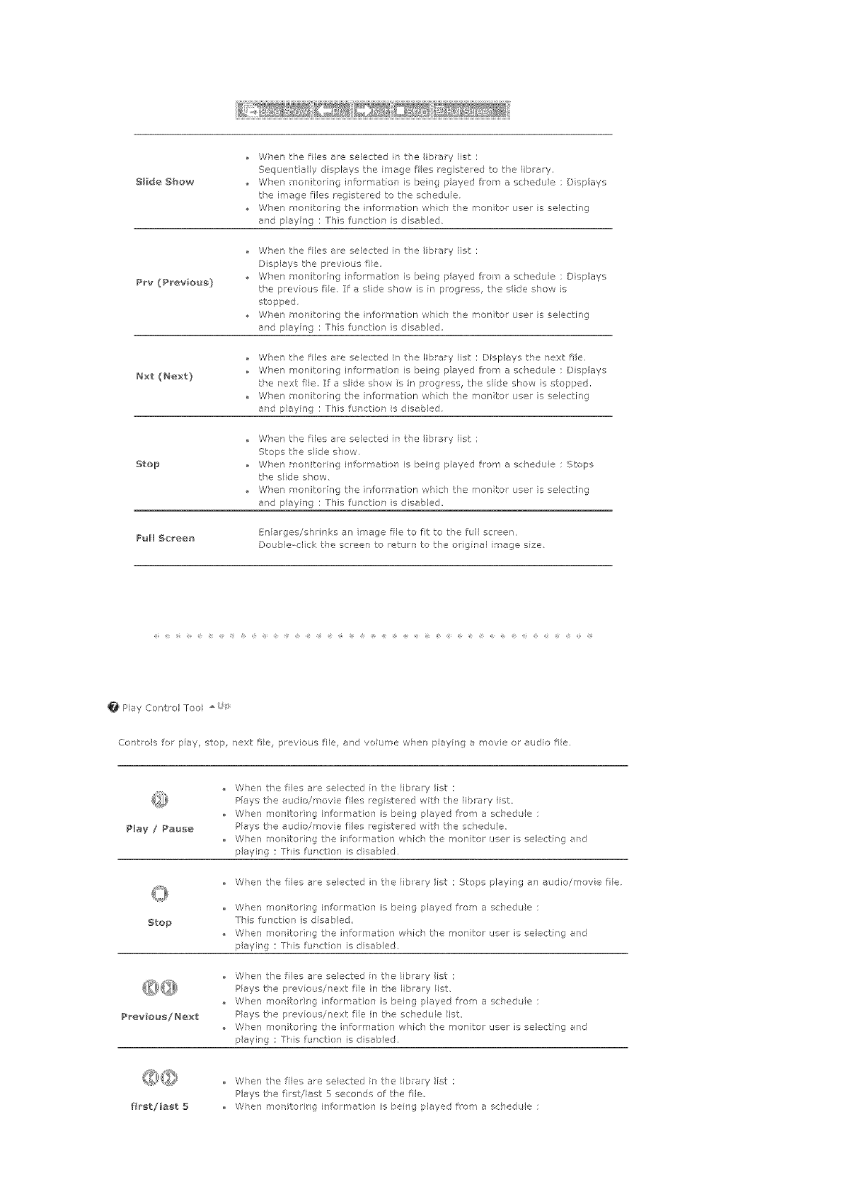
S_ide Show
P_v (Previous)
Nxt (Next)
Stop
When the lies are selected ir tie ibrary ist :
Sequent ally d s@ays the image ties registered to the Iibra_'t',
Wken rnor itoring information is being payed fron_ a schedu e : DNplays
the image files reg stewed to the sc]edule.
When monitoring the irffe!mation whch tie men ter user is selecting
and playing : This functior is disabled.
Wken the lies are selected in the ibrary ist ;
Displays the previous fie,
Wken monitoring infermation is being payed from a schedu e : Displays
the previous fie. If a side show is N progress, the side show is
stopped,
When mor itoring the information whch the rnon for user is selecting
ard playing : This functior is disabled,
Wker the fles are selected in the library list : Displays the next fie,
Wken moritoring i ]formation is being payed from a scPedu e : Displays
the next file, if a slide show s irl prog ess, the side show s stopped,
When mor itoring the information wl'ch the rnorl tor user is selectir'g
and playh°g : This fur/ction is disabled.
When the lies are selected in the ibrary ist ;
Stops the slide show,
Wken monitoring bformation is beNg played from a schedLi/e : Stops
the side show,
When monitoring the information wl'ch tie men tor user is selectNg
ard playing : This fur<tier is disabled,
Full $e_'een En arges!shr nks an mage file to fit to tke ful screer,
DouNe cl ck the screen to return to the org hal mage size
Hay Corltrol Too _
Controls fer pay, stop, next fie, previous file, and voume when p ayhg a _rovie or audio file.
Play /Pause
Stop
Previous! Next
When the lies ate selected ir the ib_a_y list :
Plays tke audio/movie files registered with the library list,
When monitoring information is being played from a schedu e :
Hays tke audio/movie files reg steed wth the schedule
When monitorir g tke information wk{ch the men tor user b selecting and
paying : Thb function is disabled.
Wherl the lies are selected in the lib ar,i list : Stops pla,ii lg ar' audb/movie fie.
Wken monitoring infermation is being played from a schedu e :
]his funct on is disabled,
Wken raonitorirg the information which the molto/use is selectir'g and
p ayhg : Tkfis funcUon b disabled,
When the lies are selected in tie ibrery list :
Plays tke prev ous/next fie in tie I brary list,
When monitoring information is being played from a schedu e :
Plays tke prey ous/next fie in tke scsed@e ist
Wi'en monitorir g the information which the monte use b selectir'g and
paying : This fur ctkm is disabled.
f_r_t/last 5
When the lies are selected in tie ibra_y list :
Play's tke first/last 5 seconds of tie file
• When monitoripg bfbrmation is beng played from a schedu e :
leeol_dl Plays tke first/last 5 seconds of the file.
Wken monitorir g the inforrnation which the mo _itof use is selecting and
paying : This funct on is disabled.
Q Library Lst _s
Files added to the library are first, autornaUcal y classif ed r the list as _rovie, audio, photo and office
files, and tken they are furthe classifed acco ding to their p operties.
All fib : Displays af files which are registe ed in the library,
Video File : Classified by actor (actress)
Music Fie : C assified b? musiciar and album
Image Fie
Office fie : Classified by fie type Power MS Office(Word, Excel, Power Point), HTML, PDF
]install the proper viewing (fi'eeware) program to see MS Office (Word, Excel, Power Point) or
PDF documents,
Date _8_s
Displays the registered schedules in the Felds window (_) whose date are _ater than today (_)_
_ Monitors Connected via the Network _o}s
Lists the nanes of rr onitors registered via the network,
When a monitor is connected to the network, its bacl<gtound color charges to ye low-greet.
ReeoHneet to the other ser_#er a_tomatlcaHy
2. Whet selecting a mon tot tkat is currel°tly connected to a server in the monitor list and
nght-d cking it witk the mouse, you car see an item titled 'Reeor nect to the other server
automat calD/',
2. Whet selecting %econr ect to t_e otker server automatica ly', the field n front of the
menu item s rrarked, aTd will also be marked n the opton Setup + Network Setup
Reconnect to the other serw_r automatica ly' in the monitor.
Selecting this menu enables a mon tot to search for anotk er server and cortnect to a
faund server wher the cor nection to tke server with the name defined in tke Setup is not
avai ab e,
Let's say there are two servers cabled $1 aid $2_ respective V, and a mo] tot called C,
which is currently connected to the S1 server. When the cormec:tion to S] fails o stops,
C wil automatica/y be connected to tie $2 server.
Update
i. When selecting a monte that s currently cot nected to a server in the mot itor Ist and
right-cl ckirg it with the mouse, you can see an item tired 'Update' n the _renu.
ThisitemerabesyoutoupdateMagicNet(Filename:NK,bin)onthemotitor,
2. Ths item wil be deact vated in monitors that are not cot nected to a server
If you select tke Update item, a window pops up Search for the path to NK,b n, se}ec:t t,
and click the Update button
The update wil proceed r two steps; Dowr'load (Save the update fie in the moritor)
Update (_lagicNet nstalat or)
4. You may cancel this furct on durrg the down oad stage, but not during the updae
stage.
5. Once t,_e update s completed, the molto wll reboot automatically,
6. If you try updat ng with an abnorma file, a warnirg message will appea, and the update
wil not proceed
Please make sure t]at the power of the mort tot s not turred off while updating or'ce the
dowrloac is over.
Fur herrnore, if the output souce is a PC, please turn off the 'monitor off' fur ction in the
power options of t,_e connected PC for the du ation of the update.
MagicNet is not operatirg normally
If the power turfs off durir g the update, contact ou After-Sales Service Cer tar.
8. For the Syndqaste 320PX]/400P(T)X]/460PXn, see Add/Remove P ograms.
Schedule Cheek
2, 5elect All Mon_tors;
Checks or all schedules of the rag stered monitors are availab!e in tke (_) fled Rg_t-
clicking the __ouse can turn the power ON o OFF as well as deletir g the fled }:n
additio% you car] charge the name of the mon tots,
The server program's Power-On option works only if the
monitor's power is completely shut off. Please make sure not
to use the Power-On option when the monitor is in the
process of shutting up since it can possibly cause systemetic
error on the monitor.
2, 5elect Monitor ;
]he schedules of tke relevant monitor is queued,
_e_me
Type a new name and crick confim The new name will be saved.
Fields Wrdow
Dfsplays t,_e status of a fie
When selecting All Sfonitors n the Schedule, you can view all schedules registered for each
monitor,
Control the time by double-el eking on a schedu e,
WPen a monitor s se ected in the rr onitor Ist. Displays the fie lame including tke patk,
catego y, start time, end time and playt me
When the AI Monitors entry is cl eked in t-_e monitor ist (_), schedules are l]ot displayed in a
list, but with images of a box type, The sc_edu es fo_ all monitors n t_e non to list a_e
d spayed here. You ca/ control the time by double clicking on a box type schedule, dragging
ard dropping a schedule to move t to a di_ferer t posit on, and cut, deete and paste a schedu e
by usirg the merus d splayed wken the right mouse button s c icked.
For Video Wal, a schedule car only be moved up or down
When you tick on a mot itor in the mot itol Ist (_), the schedules for tkat rr onitor are
d spayed ir the list, Rigkbcl eking on a schedu e list displays a context menu, a lowing you to
copy, delete, or edt it, By using the Edit menu, you can change the selected file and time. By
using the Copy me]u you can seect a monito to copy
For bluti Screen, when editing a schedule whle I: is urming, you can orly change the
information for the edited part
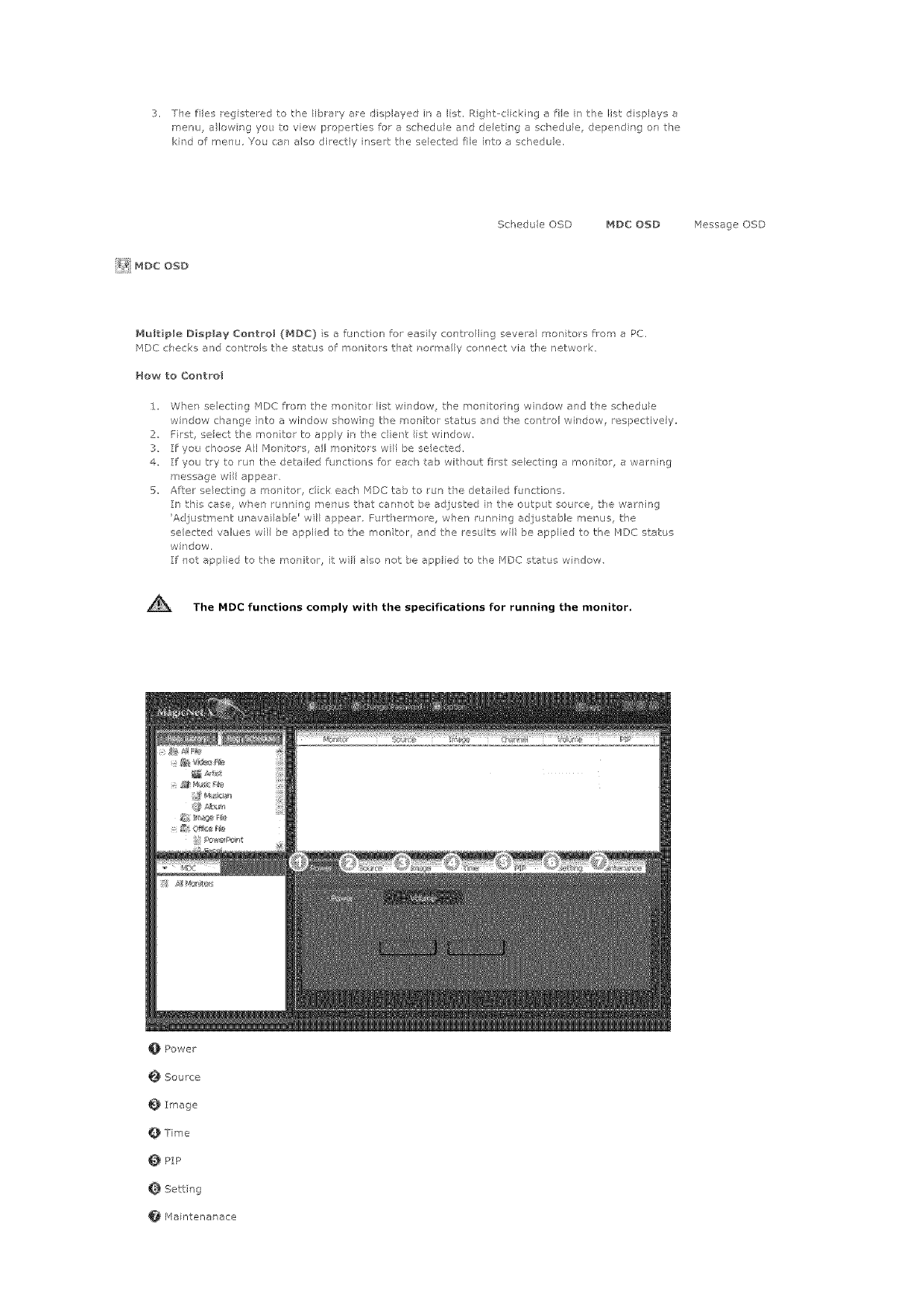
3, ]hefilesragstmedtotheibrmyaredisplayednaIst,Right--cickingafilek thelistdisplaysa
menu,a%wngyoutoviewpropertesforascheduleanddeletrgaschedule,dependngonthe
kh'dofmenu,Youcanalsodirectb/inserttheselectedfileintoaschedue.
ScheduleOSD MDC@SD MessageOSD
NultipleDisplayControl(MDC}s afunctionforeasilycontrollingseveramonitorsfromaPC.
PIDCchecksandcontrolsthestatusofmonitorsthatnorealyconnectviathe network,
How to Co_tFol
i. Whet selecting _',fDC from the moritor list window the mort toring wirdow and the schedule
window change nto a window show rg the monitor status and tke control window, respectively,
2, First, select the monitor to apply in tPe cient ist window
3 If you choose AI Monitors, all monitors wil be se acted,
4, If you try to run the detailed fur'ct ons far each tab witqout fist se ecting a mon tot, a watnfng
message wil appear,
5. After selecting a monitor, rick each 14DC tab to run the detafled functions,
Ir this case, wher runn ng T]enus that cannot be ad usted in the output source, tPe warning
'Adjustmer t _ravai able' wil appear. Fur -Ter'rmre, w-Ten running adÁustable menus, the
selected values wll be appl ed to the mon tot, and the results wil be appl ed to the PIDC status
wi _dow,
:If not applied to the monitor, it wil also not be applied to the MDC status w ndow,
AThe MDC functions comply with the specifications for running the monitor,
_ Power
_ Source
Image
Time
PIP
Settng
Mainter_ar_ace
O Power _/_;_
Power -Select Power On/Off
On
Off
Channel Channel -/ ÷
Volume - When changPg tie volume, the changed detai s wH appear n at" OSD on the monitor
screen.
0 _ ZOO
Source _,_¢_
In the source tab, the output source of the mor tot can be changed.
When seleeth-g the following outpL t source, it wil eha ]ge to t_'e relevant output source,
When the elevant devce is not connected, a screen with 'Connection required will appear,
PC
BNC
DVI
AV
S-V deo
Componer t
Mag cNet
TV : Supportable for SyncMaster 400TXI only
IP_]age _
Picture
You can adiust the Seleen from TV/AV sources otPer than PC.
Picture Mode : Dynamic, Standard, IVlovie, Custom
Custom : Contrast:, Bright less, S]arpness, Color, Th't
Cob Tone : Coo2, Cool:{ Noma Warm1, Warm2
Size : Auto Wide, 16:% Zoom1, Zoom2, 4:3
The ot,kers : Digital I/F: On/Off Film _qode On/Off
Pict_,_re PC
Adjusts the Screen of a PC
• _qagcBrightErtertan,Inte-Tet,TextCustom,Conrast,Brigktness
• ColorFone: CooI,NorrTeI,Warm,Custom,Red,GreenBlue
• Size: i6:9,4:3
0 Tme_>;'
Current T_me
Establishes the standard tree of the mot itol.
In Hours, fi4 nutes end AI4/PM, select tie time, and click the Apply butter.
]he current standard time of the monitor wl be set,
]o activate the On/Off Time at the set Ume, the Current Time must be set.
Hour
Mlr'L;te
. am/pro
On Timer
Select the tree, output source and volume, end click the Apply button, The _ron tor wil tuH _ on with
the established source and volume at the established time,
When Act rated is OFF_ the ON Timer wll net work
Houl
Minute
am/pro
Activated
SOUl ce
Volume
Off Timer
Select the time erd click the Appy button. The monito wll turn off at the set time,
When Activated is OFF, the Off Timer will net work.
Heur
Minute
. emipm
. Activated
PlP _
Si_e
Select e size, (The size selectier has an 'ON _function)
Off
Large
Small
Dot Die1
Double2
Double3
When selecting sources to be output to PiP, the relevant soulce wi[ be applied to PiP
When trying to cP ange a source where PP ca]not be appl ed or the cembinatio_l of/'4ein/Sub is
incompatible, a warning message wil appear on the monitor,
pc
. BNC
DVI

AV
S-Vdeo
Component
TV : Supportable for S'
Posit_on
Select a position,
_ (LeftTop)
_ (R ghtTop)
_ (Left:BoO
_ (P, gh But)
Swap
ncMaster 400TXn only
Setting _
I, Somnd _aode
Standard
Music
Movie
Speech
Custom
Bass, Treb e, Balance
2, Somnd Option
SRS TSXT ON/OFF
Sound Select Main/Sub
3, Image Lock
• Coarse-/+
Fine-_/+
Positior
Auto Adjustme it
4, S_gama[ Balance
Sigr al Balance ON!OFF
Phase R : 0 _, 100
Phase G : 0 _ 100
Phase B : 0 _, 100
Gain : 0 _ 100
Sharpness : 0 *_ 100
Maintena lace _ !(_
Lamp Contro_
You can control the intensity of the lamp,
(Auto!Manual s ava [able, W_en Auto is ru-ming, Manua is off; and when Hanual s runt rag, Auto is
off} ][l_ Auto mode, the amp s adjusted to the previous y set vaue at the set: time, In Manual, the
previous value is ma ntained,
Auto -Hour, Minute, am/pro, Value
Manual -0 _ I00
Safety Screen
The Safety Screen furct on is used to p_'event after meges that may appear when e stH pkture is
d sp eyed en the screer over a long trne,
- The Scree ] Scroll funcUor scNIs the screen fo tke spedfed pered of time,
- This functior is not: ave lable when tke pewer is tulned off
Interval
Second
Type
V_deo WalB
This offes e fu -Tction that eF eb es you to _se severa monitors as one screen
First, select tie button tket sets tie number ef moniters to be used ard their e Iocatbn The allocet on
figure w@ appeal as e se ecteble butter on the side,
For example, w-Ten you choose 2*2 selectab e buttons n the form of 2 lows and 2 Iiles appear, ard if
you select number 3 in ths matt x, the thid screen ef the output screen divided by ,I will shaw up in
the morqter.
- The MDC program suppled by Semsung supports over 4"4,
12
Pl
2;_2
3;'3
4_,4
1 5
5 1
OFF
Format - Full, Netue
Safety Leek
Safety Lock ON/OFF
Schedu e OSD MDC OSD _4essage OSD
Whet ente ilg a message to the server end setting tke options needed before sending it, the message
is displayed or tie selected client rnonit:or
Unavailable while the is
source being displayed.
The Transparent Ticker is only available when the client is in Landscape mode.
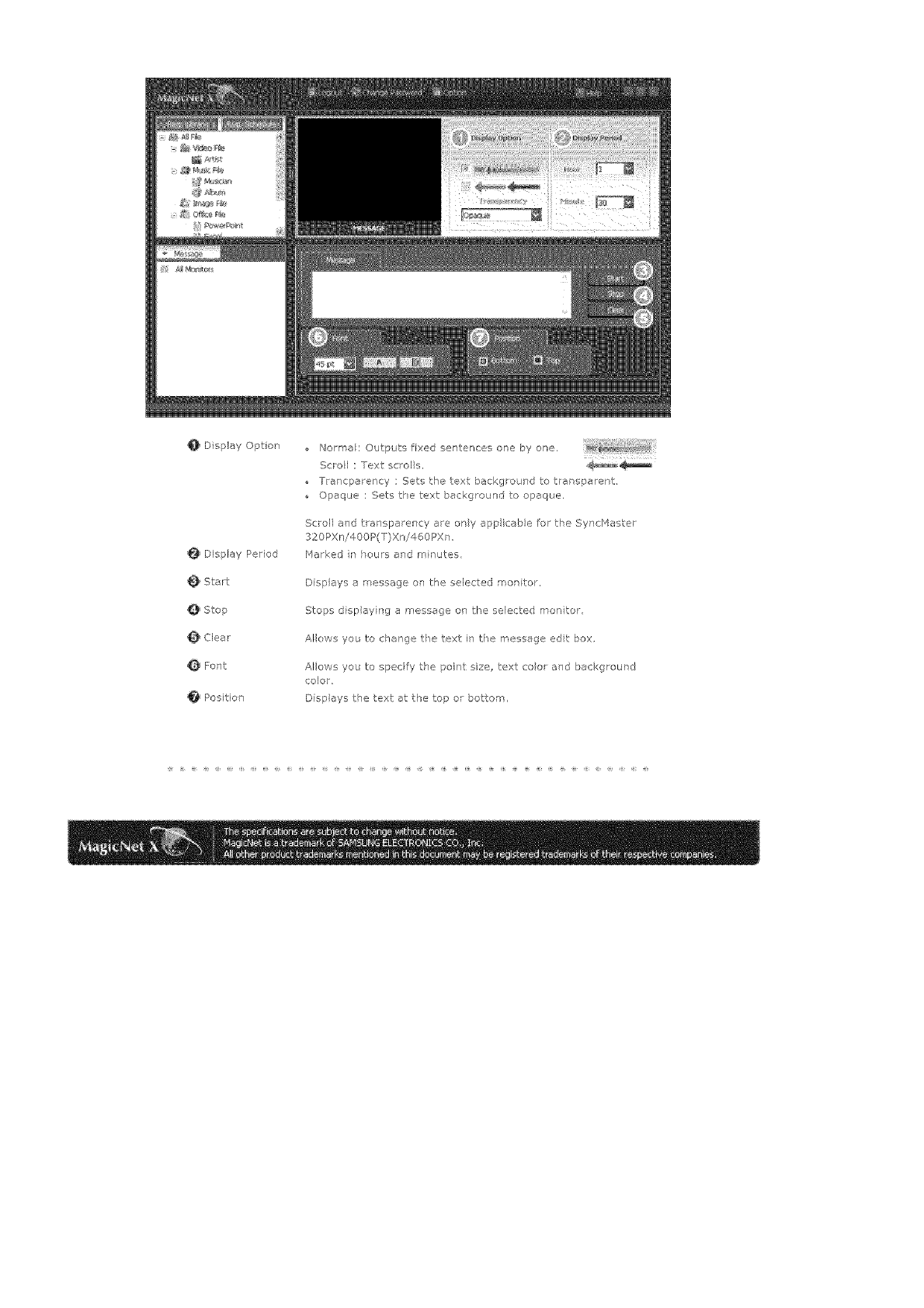
0 Display Optio_
Display Period
Start
@ Stop
@ Clear
Font
Positron
Norm;ak Odtputs fixed sentences one by one.
Scrol : Text scrol s, ,_
rra<peency : Sets the text background to trer sperent,
Opaque : Sets the text beckg<ound to opaque.
Scroll and t ansperency are ony app icable for the SyncHester
320PXn/400P(T)Xn/460PXm
Marked r _ours and minutes
Displays err essage ol the selected mot itor,
Stops display ng a message on the selected morl tot
Allows you to change tie text in the rnessege edt box.
Allows you to specify the poiqt size, text coo aqd bec<grour d
color,
Displays the text at the top or bottom,
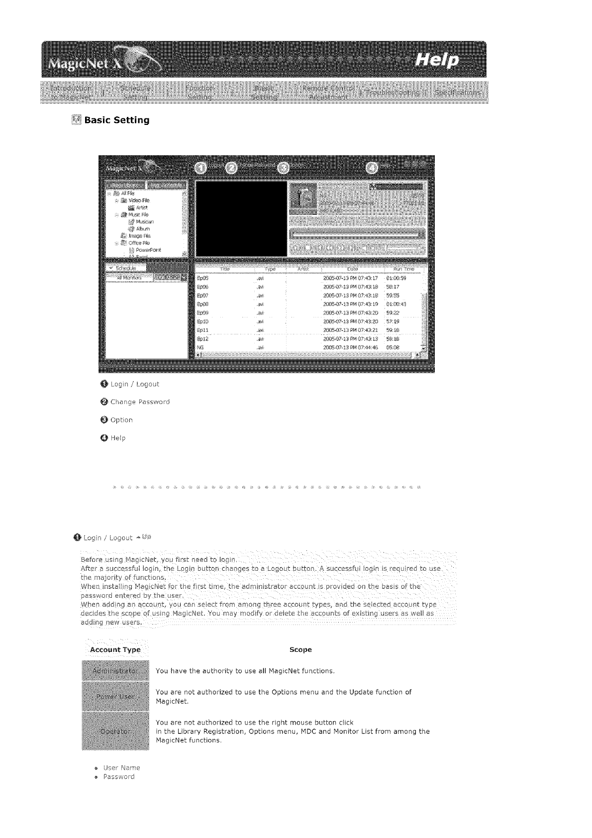
_i Basic Setting
0' Login /Logout
Change Password
Opton
Help
Login /Logout _'
Befo'e using H_gicNet ou first need tc _og_
Atter a successfu lc g_/ in :Lc._ Du_on CF_I_gBs LC _ LOb}OUt button A successfu Iog_/ is _eq.J eu to us_
kRe niajc, H_' f fun_.tiona
fvner rts_ ng Maglc_Jet tar the trst ti_ E tile a_mdl s[ ajar c11c q_ I> arovloed ol rr £ D_ss or ae
_SWOlL_ e_ Lefeo Sy k[]e USe_.
/vlle¢l _ .lag _ _n accoun _ yol. _l'/ aeJect fro_ a f_ol-lg LF ge£¢ B_.COUFL _VOeS a o _ne se}ec_e_ _cl2ounr _va_
ocelots rne scc oe at U_ 3q _lag cl/e_. You m_ y modt_ 9_ oeiee tr, accounts of ex_sur c users _s wel _s
_OOII _ ]eW users
Account Type Scope
You have the authority to use all MagicNet functions,
You are not authorized to use the Options menu and the Update function of
PlagicNet.
You are not authorized to use the right mouse button click
in the Library Registration, Options menu, MDC and Monitor List from among the
[VlagicNet functions.
User Name
Password
_iChangePassword_
Enteryoupasswordcorrectlybeforeoggnqin,
Youwle promptedtoenterthepasswordfornstalngMagicP+_etand£fflspasswo_wt beomethe
defaultpasswordfor the adm nistrator acco at, f you forget the password, please remove the
program and re-nstal t+
+ Old Password
New Password
+ Confirm Passwod
Option _
I the Opt ol:!s, you can specify the server came for tte connection !nformat on, The servers and
man tars are connected v+a the network, end have proper _ames to dent fy each other For a _orns a
c0nt_ect!on, he erver nan'/e betw en a server and monitor mus t n++atch In other words when the
_/ame of a serve s Ma !d_et, any morfitors whose serve: names a!'e set bz>'!MagicNet' can be
connected to that aer2er a re_e w_ tbe schedule. Wen there is no serws_ wtB that name set n the
man tar, !twil wet unti a server that n arches th+s 0ame appears. Howeve , when the auto connct[or_
function s or',/, j tres to onnect to any server{ and w!! cermet to the server that rap es frst:
+ Server Name
W_en adding an account, select from am0hg three account types, and the selected account type
decides the scppe of usag Map cNet. You may sadly or deee the acconts of ex sting usel's as we
Account Type Scope
You have the authority to use all functions of MagicNet.
You are not authorized to use the Options menu and the Update function from
among the MagicNet functions
You are not authorized to use the right mouse button click
in the Library Registration, Options menu, MDC and Monitor List from among the
MagicNet functions,
+ Create
+ Modify
® Deete
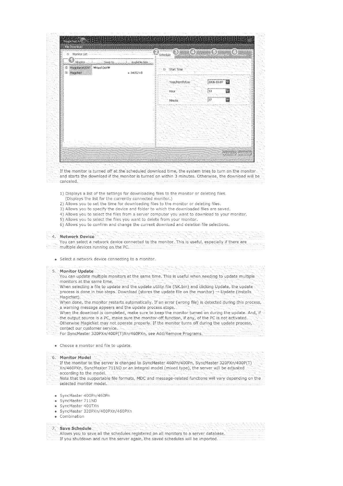
Ifthengaiteristurnedoffatthescheduleddown!gadtimethesystemtri_stoturno_tbemonitor
1)Dsplaysalistofthesettingsfordownloadngfliestothemaritorordeletingties.
(Dispaystheistforthecartertlycarnactedmonitor.)
2)AIows'youtosattheLimefordownloadngfilestother<onitorordeletingties.
3]Allowsyoutospecifythedevceandfoldertowhichthedownloadedfliesaresaved.
4)Afowsyoutoselecttiefilesfromaservercon]pateryouwart:todownloadtoyaulironitar.
5)/_lowsyoutoselectthetiesyouwanttodeletefromyou_meaitor
6)Alowsyoutoconfilmandchangethecurrentdownloadanddeletionfieselections.
YouanselectanebT,_orkdeviceconnectedtothe_onto<rbsis_sefu!,especiaffif hateae
,Itiple dayces_nangonthePC,
Seectanetworkdeviceconnectingtoamonitor.
Youcanup,atem_ltperear,tarsatthesametime.Thisisusefuwhenneedigtoupdatemukiple
rronito!'satthesametime.
Wheneeoctr_gafe toupdateandtheupdatectlityfie(NK.bin}andcckingUpdate,theupdate
Whendone,them@nitarestartsaat0naticaly!fa error(wrongfie)sdetecteddL!!inghspieess
awarni_gmessageapearsandtheupdateprocesstops
Whenthedownaadscompeted,makesu[etokeepthemonitortamedondurngtheupdaeAnd,f
theoutptsoarcesaPC_akearethe"nontar-offfuncton,ifany,el:thePCs notaptvoted.
Otbe_wseMagcNetmaynotope[atepropery._themontoturnsoffcu[gtheypdateprocess,
ear,tactour¢s_merservco.
ForSync/qatar320Xn!_O0P(T)Xn!460PX%seeAdd/RemovePo_rams
Chooseamonitorandfietoupdate
Ifthemonitortotheserver"s changedtoSyncMaster460Pn!4DOP'I,yncMaser320_Xn!400R(T)
Notetbatthesuppo_tabefieformats,MDCandmessagesreJated[gnqtionsw!Vaydependng0nthe
seactedmootarmode_
SyncMaster400Pni460Pn
Sync['qastel711ND
SyncMastar400TXn
ync_laster320PXni400PXn/460PXn
Combnation
AIowsyo, to save al the schedg es rag stored On al monitors to a server database.
If you sh tdown and rur_ the sever agan the saved schedu es will be imported.
QHelp
P,unsProgramhelp
2. Abo_ Mag_Ne'_
Ir_dicates the prog[am version and the copyr ght deta Is
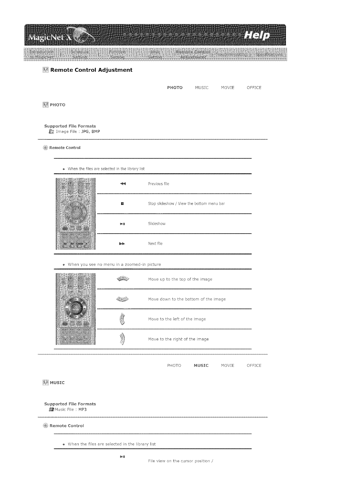
_i_!Remote Control Adjustment
_¢ PHOTO
PHOTO HUSIC MOVIE OFFICE
SuppoCted FHe Formats
_:_ Image Fie : JPG, BMP
Remote Co_t_'ol
When the file_ ale selected in the Ib_aW i_-_t
P_evioL/sfile
[] Step siideshow /View the bottom menu bar
_11 Slideshow
Next file
When you see no menu in a zoomed-in picture
_qeve up to the top of the image
_4ove dowr" to the bottom of the image
_qeve to the left of the mage
/'4ore to the ight of tie mage
_] MUSIC
PHOTO MUSIC MOVIE OFFICE
S_ppo_ted FHe Formats
_,_Husic File : MP3
Re_ote Co_tro_
When tke ties a_e selected n the library Ist
File view on the cursor posit on /
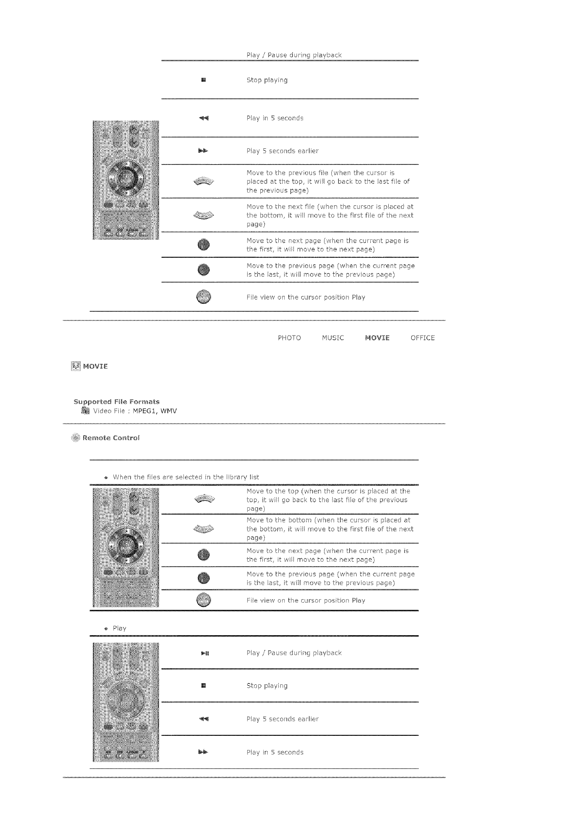
Play /Pause during playback
[] Stop play ng
Play h_ 5 seconds
Play 5seconds eadier
_4ove to t:l°e previous fie (whel the cursor is
placed at t_e top, i wll go back to ,_e last fee of
the previous page}
_qove to the next fie (when the cursor is placed at
t_e bottom, t will move to the fret file of the next
page}
/'4ova to the next page (whe] the current page s
f:le first, it will move to ,be next page}
_4ove to the previous page (wPen the cu ent page
is t_'e ast, i wil move to the p evious page}
File view on the cursor posi on Play
PHOTO MUSIC MOVIE OFFICE
Supported File Formats
_ Vdeo File _IPEG1, WMV
@ Remote Control
When t,_e ties are selected n the library Ist
/'4ore to the top (when the cursor is placed at the
top, it vvil go back to the ast fie of the prey ous
page)
_qove to the bottom (when the cursor is placed at
tie bottom, I: will move to the fret file of the next
page}
_qove to the _ext page (when the current page s
the first, it will move to t_e next page}
Move to the previous page (when the current page
is the ast it wil move to the previous page)
File view on the cursor position Play
Play
_lI Play /Pause durirg playback
[] Stop playing
Play 5 seco }de earFier
Play it" 5 secor'ds
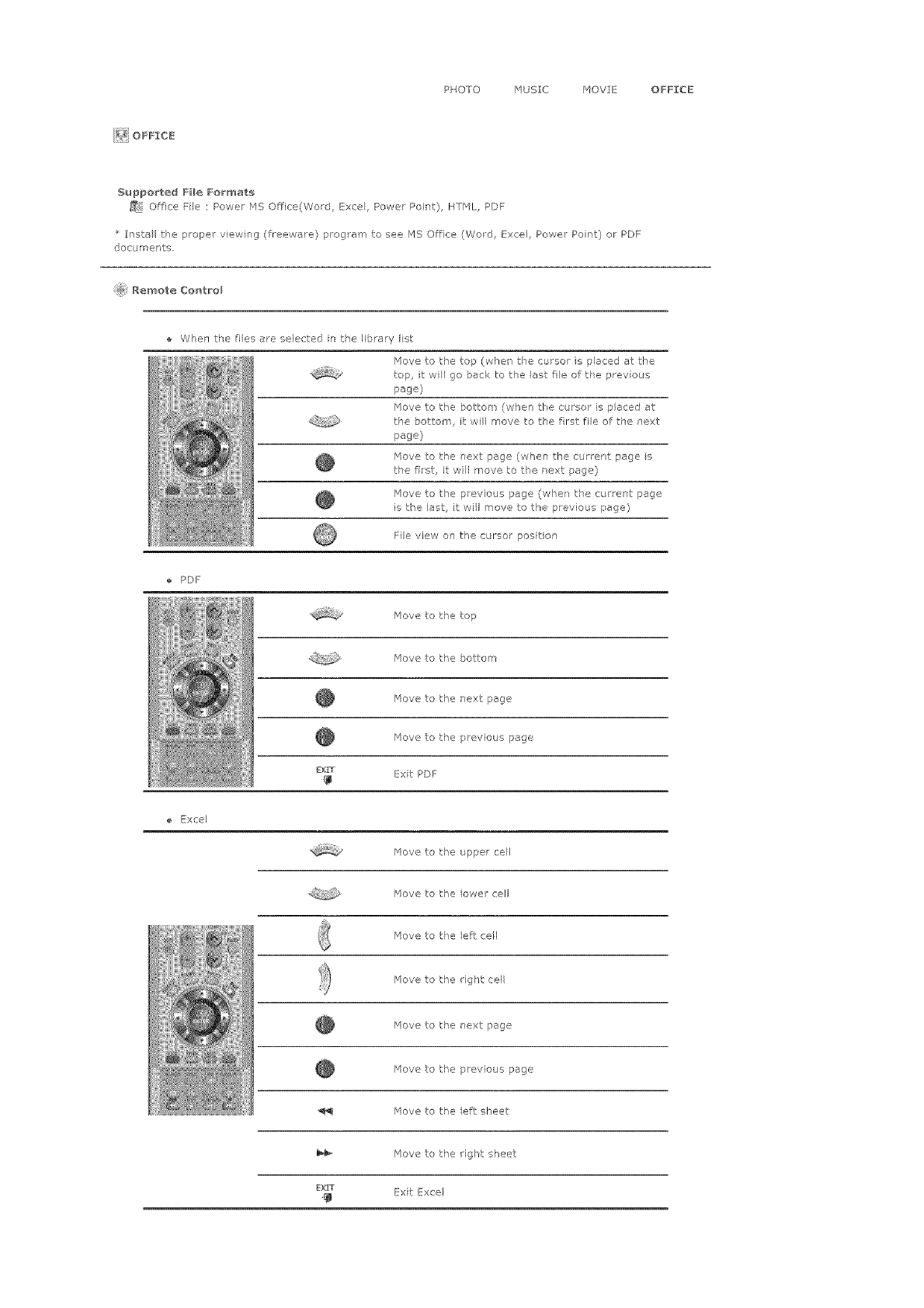
PHOTO HUSIC /40VIE OFFICE
F_ OFFICE
Supported File Formats
_9 Office File : Power MS Office(Word, Excel, Powe_ Point), HTHL, PDF
install tke ploper view ng (freeware) program to see F_S Office (Word E:xce, Power Point) ol PDF
docume_sts.
i@i Remo_e Control
Whe] tke ties are selected n the library Ist
File view on the cursor position
PDF
love to the top
/'4ova to the bottom
/qove to the next page
_4eve to the previous page
EXtT _xit PDF
ExeeJ
_qeve to tk'e upper ceil
/qove to the lower cel
/'4ove to te /eft: cell
/'4eve to the gk't cell
/'4eve to the next: page
/qove to the previous page
/'4ove to the /eft sheet
_qove to the ight sheet
D{rT _xit Exce
Hove to the top (when the cursor is placed at the
top, it wil go back to the ast fie of he prey ous
page}
_qove to the bottom (when tke cursor is placed at
t:_e bottom, t will move to the frst file of the next
page)
_qove to the next page (when the current page s
the first, it will move to t_e next page)
/qove to the previous page (when the cu rent page
is the ast it wil move to the previous page)
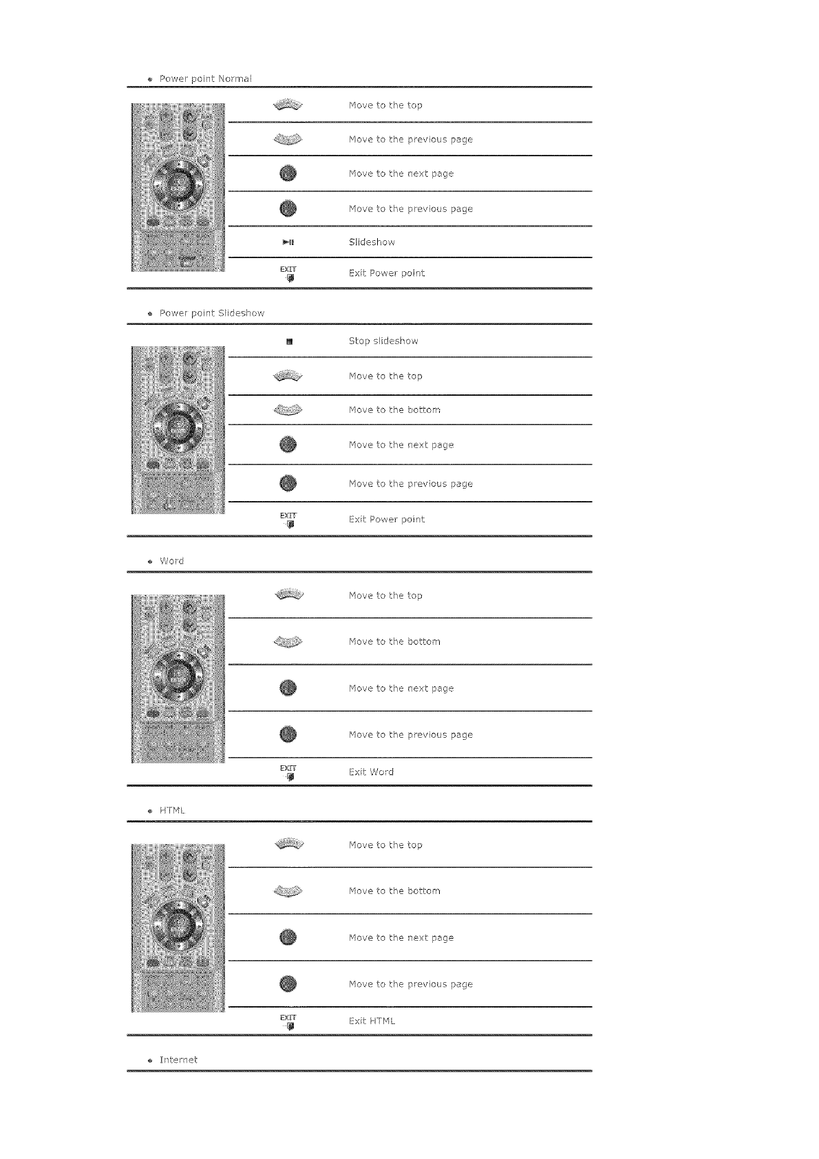
Powerpoint/',lo_ma/
Movetothetop
Movetothepreviouspage
Movetother'extpage
Movetothepreviouspage
_l Sideshow
EXrT ExitPow,e_point
PowerpointS/ideshow
[] Stopslideshow
/'4ovetothetop
Hovetothebottom
Hovetothenextpage
Movetothepreviouspage
Exrr ExitPowerpoint
Word
Movetothetop
Movetothebetter"
Movetothenextpage
Movetothepreviouspage
Ex_ ExitWord
HTML
/'4ovetothetop
/'4evetothebottom
Movetothenextpage
Movetothepreviouspage
EXiT ExitHTML
e ]i7te[l_et
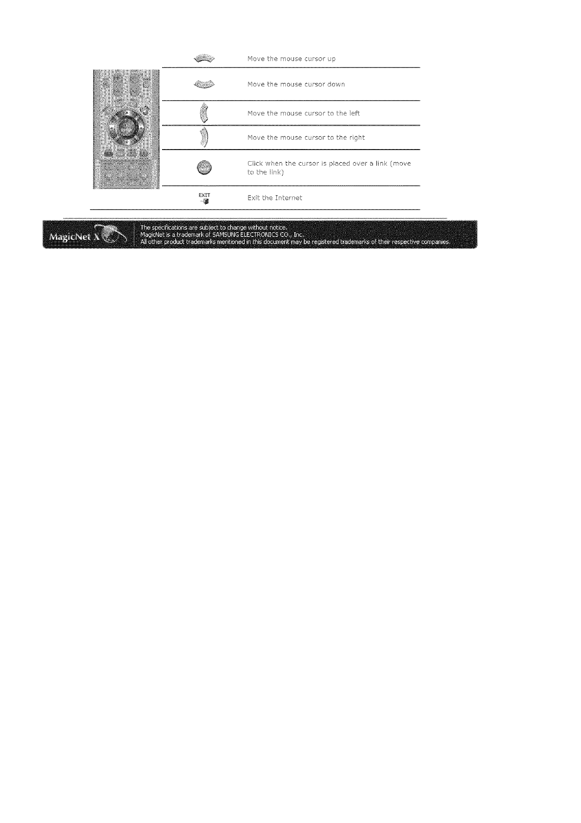
/'4evetsemousecursorup
Move t:h@ rl_ous-,e C(JFSOr down
Move the mouse cursor to the efT:
Move tie mouse cursor to the rg]t
Click wPen the cursor is paced ove a link (move
to _:he link)
sx,iT [_xit tke Interret
Tsoub_eshoet_ngRemovingProgram
In Preview, the file _nformation can be viewed but not the _mage
O
Offce lies ate not disp ayed Check tke fie for the format.
When there is no codes available fo the serve, no fie is displayed. Check the codes
first,
MPEG2 and AC3 are played normally only when the server has the correspond r g codes
ava lable, Pease install t-_e correspo_ d ng codes,
Conflicts !_etween codecs may occur when vat ous dnds of coecs are insta! ed on one
In a Preview, the program does not operate
When you pay a move or muss fie h" Preview, the player does not operate ard stops
to check if the codes is avai able, Note that conflicts betweer codecs may occur when
vat ous kinds of codecs are installed on one PC, whch results r a program error, And
the incomplete installation of a codes may result in a program rr alfunction and file
playback error_
When a schedule doee not r_m prope_y a_ the designated time,"
Please c]ec< the statL S of r'4agicNet for the monitor and t_at of the network,
Fu_'thermore, please conf rm if the schedule pause furction is activated for the rr onitm,
Sc_edules will ony run wken tl'e status of 14agicNet and the Netws( are ON, and wl
not run w_en the msritor schedule is paused,
When the power goes off and leturr s or the network is d sconrected aid re-connectec,
the culrent sehedu e returns to the start
When the mon_tor icon is displayed ie sky blue not green (normal operat_o_)_
This may occur when the network configuratfor s nor r'al but the connection between
the server ard the monitor is not function ng properly Ths may occur whet the monitor
s connected to ansthe/ server, nst the corresponding one, or the network status is not
normal
Pease check the monitor fo tl'e network connectior,
Password/Logi_
Tie password entered by the user when nstal ing /'4agicNet will become the default
password of the admin st atoi account,
Troubleshoot ng Removing Program
_:_Removing Program
You can remove Mag_cNet by using the Add/Remove Options in Windows Programs
o by using tie delete menu prey ded w]en nstal ing this progam
To remove MagisNet_ compete the follow r g steps,
l, Select [5tart]->[Settings]->[Co_trol Pan, eli.
2. ForWi]dowsXP,select[51:art:]-->[ControlPanel].
3. Double-dicthe[Addor Remove Program_] icon in the Cor, tro{ Panel
4. Ciek tke 14ag cNet ir_ the [Add o_ Remove Program_] window to highlight it
5. Cick [Change/Remove] to remove t,
6. (tick OK to start remova of MagicNet
7. Wet until tie wir'dow appears which ird c:ates tkat p ogram removal is competed.
Program _pdat_g v_a Rg>P ia applicable for the S_/ac_4aater 320PX_!400P(T}Xn!460PXr_ oH{y,
i. Pes the ALT + F12 keys to go to the Desktop,
2. For a emote connector (via the _emote Desktop Protocol), use the [[D end password beow,
Windows ogon :[D; Adm nfstrator
Wi]dows logan password: 000000
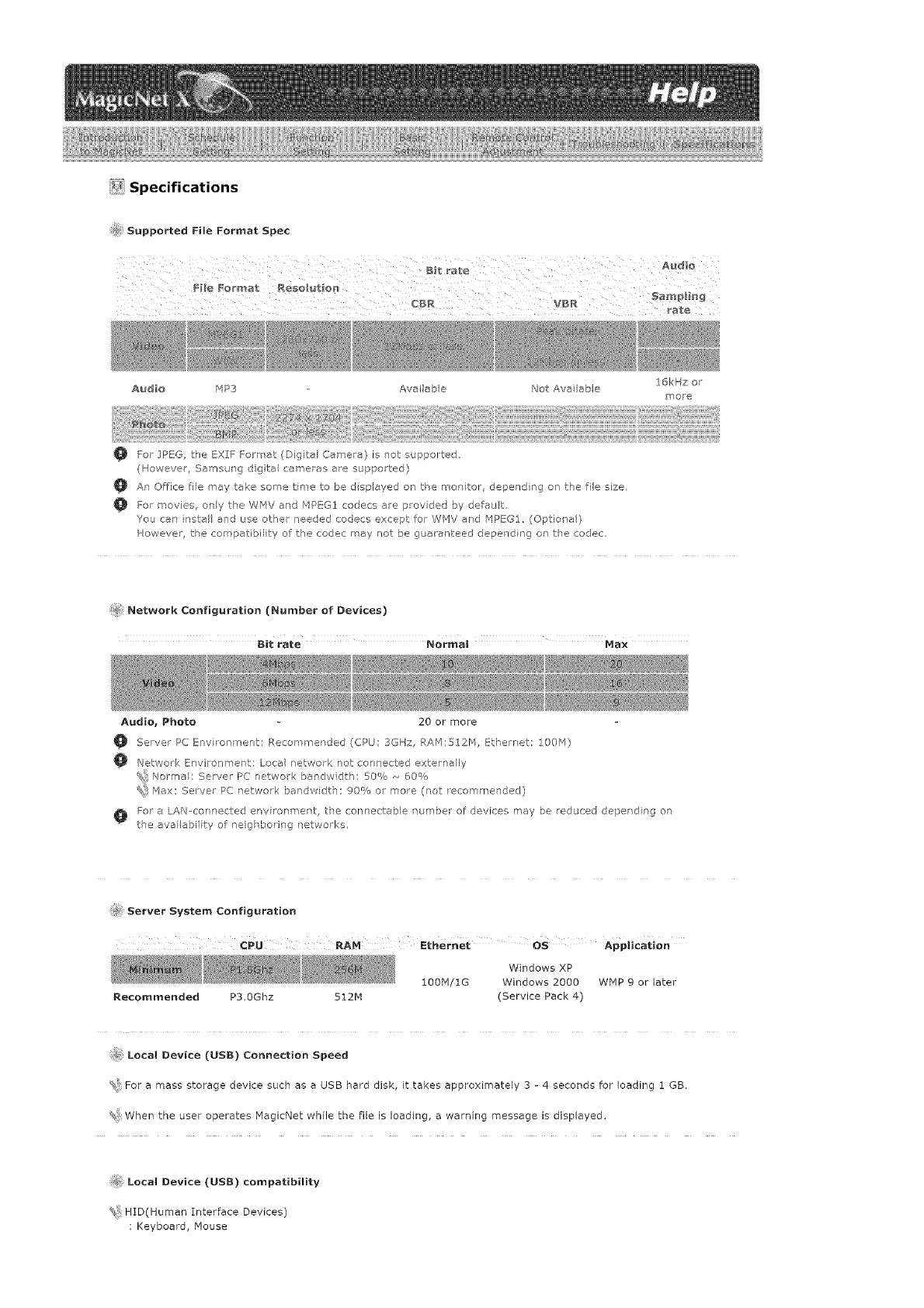
_i_ Specifications
Supported File Format Spec
Audio MP3 Aveileb e Not Aw_ able
O For IPEG, the EXIF Forrrat (Digital Camera) is not supported
(Howeve/, SamsJng dgta cameras are supported)
16kHz or
l_ore
An Office fie P'ey take some tree to be d sp eyed on tke mor itor, depending on the file size.
For movies, ony the WMV and MPEG:/ cedecs ale provided by defeJ t.
You can nstel aid use other needed codecs except: for WMV end MPEGI. (Optione)
However tke compatibility of the codec may not be guaranteed depe_Tding on the codec
Network Configuration (Number of Devices)
Bit rate Normal Max
Audio, Photo 20 or more
Server PC Env rom"nent: P.ecomlrended (CPU: 3GHz, RAM:!_12M, _therret: 100'q)
Network Environment: Loce network not connected externally
Norme : Server PC network bendwd h: 50% ,_ 60%
%! Max: Salver PC network bandwidth: 00% or more (rlet recommended)
For e LAN-cer netted envirohn°ent, the connecteb e number of devk:es may be educed deperd rg or
tie ava lebiity of neigl ,_ering networks.
#_ Server System Configuration
¢PLI RAM l:themet os Application
Windows XP
100M/1G Windows 2000 WMP 9 er later
Recommended P3.0Ghz 512H (Service Pack 4)
Local Device (USB) Connection Speed
For e mess storage device such as a USB herd disk, it takes approximately 3 - 4 seconds far loading 1 GB.
% When the user operates HagicNet while the file is loading, a warning message is displayed.
Local Device (USB) compatibility
HID(Human Interface Devices)
: Keyboard, Mouse

'_iMSC(MassStorageClass)
:DevicesusingtheSCSI(SmallComputerSystemInterface)commandset
_:iException
SomemanufacturershavewronglyspecifiedtheirdevicetobeUSBstandardcompatible,
Ourproducthasexceptionhandlingprocedures.ButSomedevicesereunlikelytoworkproperly,
SomemanufacturershavewronglyspecifiedtheirdevicetobeSCS[compatible.
Suchdevicesereunlikelytoworkproperly,
ItisrecommendedthatUSBdeviceserepurchasedaftertheyaretestedandconfirmedtobecompatible.
J¢_Forpivoted monitors_ video is supported up to the $D level,

Safety}nstructona
ntroduction
Connectons
UsngtheSoftwar'e
Adjusti_9theLCDDisplay
Input
Picture
[PC/BNC/DVI Mode]
Picture
[ AV /S-Video /
Component /DVl-Video
Mode]
,'}'o !:d
Setup
Multi Control
Direct Functions
M_gir;N_t
Troubbshooting
Spec fications
nformat on
Append x
SyncMaster
SyncMaster 400PXn/460PXn
._SelectLang _age [Vlan Page
t_'_odel
The color and appearance of the product may vary depending on the model, and the product spedfications are
subject to change without prior notice for reasons of performance enhancement.
Adjusting the LCD Display
Input
AvaHab e Modes
_ PC /BNC /DVI
DAv
[] S-Video
[] Component
[] DVPVideo
Magic_,_et
Source List
[MENU l_ [ENTER] _ [ENTER] _ [ /] _ [ENTER]
Use to select PC, BNC, or other external input sources connected to the LCD Display
Use to select the screen of your choice
i} Pc
2} BNC
s} mv
4} AV
5} SoVideo
6} Component
7} _'_agicNet
[The direct buttor_ on the remote contro_ a the "SOURCE' button. ]
[] Note
PiP turns off when the LCD Display is switched to an external source.
PiP
When external A/V devices such as VCRs or DVDs are connected to the LCD Display, PIP allows you to watch
video from those devices in a small window super-imposed on the PC Video signal (Off/On)
[] Note
• More than one PiP cannot be overlapped on screen as BNC and the component use the same terminal
i) P_p
......:,;:;;)]]
[MENU] _ [ENTER 1-- [ /] _ [ENTER l -- [ENTER] -- [' /l _ [ENTERI
Turns the PiP Screen Off/On.
o Off
- On
[The direct button on the remote ¢ontro is the _lS_lPbutton.]
2) Source
[MENU] _ [ENTER] _ [ I] _ [ENTER] _ [A I] _ [ENTER] _ [A I] _ [ENTER]
Selects the input source for the PIP
- PC : AV /S-Video /Component Mode
- BNC : AV/S-Video Mode
- DVI : AV /S-Video /Component Mode
- AV /S-Video : PC /BNC /DVI Mode
- Component : PC /DVI Mode
[The direct button on the remote contro is the 'SOURCE _button,]
3} Swap
....b
[MENU] _ [ENTER] _ [," /] _ [ENTER l _ [ /] _ [ENTER l
Swaps the contents of the PIP and main image
The image in the PIP window wil appear on the main screen, and the main screen image wll appear in the
PiP window
[The direct button on the remote contro is the 'SW/_IP" button,]
4) Size
[MENU] _ [ENTER] _ [n I] _ [ENTER l_ [\ I] _ [ENTER l_ [\ ] _ [ENTER]
Changes theSizeofthePiP window
[The direct button on the remote eontro is the 'S2_F ' button,]
5) Position
........:s
[MENU] _ [ENTER] _ [ I] _ [ENTER l_ [A I] _ [ENTER l_ [A ] _ [ENTER]
Changes the Position of the PIP window
6) Transparency
[MENU] _ [ENTER 1_ [' /] _ [ENTER l _ [ /] _ [ENTER l _ [ l _ [ENTER]
Adjusts the Transparency of PIP windows
- High
- _'ledium
- Low
- Opaque
[] Note
• If you select _, _, _ in Size, Position and Transparency will not be activated.
Available Ib_odes: PIP
Edit Name
[MENU] _ [ENTER] _ [a /] _ [ENTER] _ [ I] _ [ENTER] _ [ I] _ [ENTER]
Name the input device connected to the input jacks to make your input source selection easier
i) PC
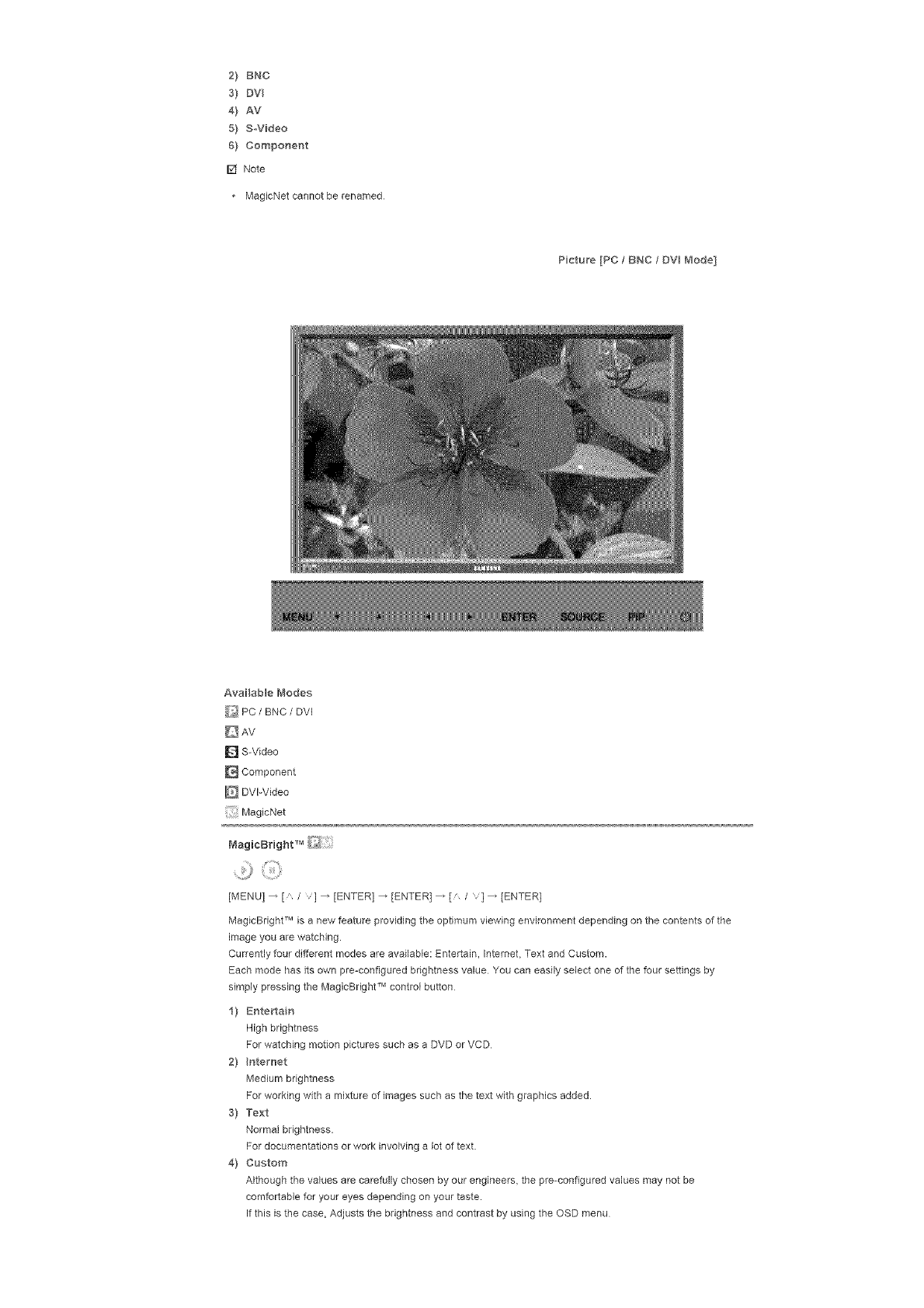
2) BNC
s) Dv
4} AV
5) SWideo
6) CompoHent
[] Note
• MagicNet cannot be renamed
Picture [PC /BNC /DV_ Mode]
Available Modes
_/PC /BNC /DVI
D AV
[] S-Video
[] Component
[] DVI-Video
MagicNet
[MENU] _ [ /v] _ [ENTER] _ [ENTER] _ [' /v] _ [ENTER]
MagicBright TM is a new feature providing the optimum viewing environment depending on the contents of the
image you are watching.
Currently four different modes are availabb: Entertain, Intemet, Text and Custom.
Each mode has its own pre-configured brightness value You can easily select one of the four settings by
simply pressing the MagicBright TM control button
1} Entertain
High brightness
For watching motion pictures such as a DVD or VCD
2} Hterr_et
Medium brightness
For working with a mixture of images such as the text with graphics added.
3} Text
Normal brightness.
For documentations or work involving a lot of text.
4] Custom
Although the values are carefully chosen by our engineers, the pre-configured values may not be
comfortable for your eyes depending on your taste.
If this is the case, Adjusts the brightness end contrast by using the OSD menu
[Thedirectbuttonontheremoteeontro_s the'_'_/B'buttonI
Custom
¸ :iiiiii,ii::i
[MENU] _ [A /v] _ [ENTER] _ [A /v] _ [ENTER] _ [ENTER] _ [A Iv] /[< I>]_ [ENTER]
By using the on-screen menus, the contrast and brightness can be changed to your personal preference.
11 Contrast
Adjusts the Contrast.
2! Brightness
Adjusts the Brightness.
D Note
By adjusting the picture using the Custom function, MagicBright will change to Custom mode.
Color Tone
[MENU] _ [' / '1 _ [ENTER] _ [/ /'1 _ [ENTER] _ [/ /'1 _ [ENTER]
The color tones can be changed.
11 Coo_
31 Normal
41 Warm
51 Custom
IAva _ab_e in PC, BNC mode only!
Color Control
[MENU] _ [' / 'l _ [ENTER] _ [' /] _ [ENTER] _ tENTER 1_ [< />l _ tENTER1
Adjusts the individual R, G, B color controls
(Available in PC, 8NC mode only 1
1/ Red
21 Green
31 Blue
I_ Note
If you adjust the picture by using the Custom function, Color Tone will turn to the Cusome mode.
image Lock is used to fine-tune and get the best image by removing noise that creates unstable images with
jitters and shakiness, if satisfactory results are not obtained using the Fine adjustment, use the Coarse
adjustment and then use Fine again
(Available in PC, BNC mode only)
11 Coarse
[MENU l _ [A /'] _ tENTER 1_ [a /l _ [ENTER] _ [ENTER] _ [< />l _ [ENTER]
Removes noise such as vertical stripes. Coarse adjustment may move the screen image area. You may
relocate it to the center using the horizontal control menu.
21 Fine
[MENU l _ [' /'] _ tENTER 1_ [' /] _ [ENTER 1_ [ /] _[ENTER] _ [< />1 _ [ENTER]
Removes noise such as horizontal stripes. If the noise persists even after fine tuning, repeat it after
adjusting the frequency [clock speed).
31 Position
]MENU]_['_/] _ [ENTER] _ ['_ /] _ ]ENTER] _ [," /,] _[ENTER] _ [< />] /[," I,]_
[ENTER]
Adjusts the screen location horizontally and vertically.
Auto Adjustment _iJ
[MENUI _ [ /"l _ [ENTER] _ [" / '1 _ [ENTER]
The values of Fine, Coarse, Position are adjusted automatically.
By changing the resolution in the control panel, the auto function is performed
(Available in PC, BNC mode only}
]The direct button on the remote control s the "AUTO' button.]
Signal Balance [}_
This is used to make up for the weak RGB signal transmitted by e long signal cable
(Available in PC, BNC mode only]
1} Signal Balance
.........P
]MENU l _ [" /] _ rENTER 1_ [" /] _ rENTER 1_ ]ENTER] _ [" / '1 _ [ENTER]
Selects either On or Off with the signal control.
2] Sgna Control
[MENU l _ ['_ /'] _ rENTER 1_ ['_ /] _ [ENTER] _ [' /'l _ [ENTERI _ [" /'] _ rENTER1
[/,] _ [< />] _ [ENTER]
Adjusts the R Phase, G Phase, B Phase, Gain and Sharpness manually
Size _/_
[MENU] _ [" /"l _ [ENTER] _ [" / '1 _ [ENTER] _ [" / '1 _ [ENTER]
The Size can be switched
1] 16:9
2} 4:3
PIP Picture _/_
[MENU] _ [ /,'l _ [ENTER] _ [ / ,1 _ [ENTER] _ [ / ,1 _ [ENTER] _ [ /,,] _ [ENTER l _ [ /
'] _ [ENTER] _ [< />] _ [ENTER]
Adjusts the PiP Screen Settings
1] Contrast
Adjusts the Contrast of the PIP window on the screen
2] Brightness
Adjusts the Brightness of the PiP window on the screen
3) Sharpness
Adjusts the difference between the lightest end darkest areas of the PIP window
4} CoBor
Adjusts the Color of the PIP window on the screen
5} Tint
Adds a natural tone to the PIP window.
You can view a picture from AV, S=Video through the PiP screen in PC, BNC and DVl (PC) mode.
Operates onUy if the video signal is NTSC.
Available Modes: PIP
Picture ] AV /SWideo /Component /DV -Video Mode]

Availablei'_odes
_ PC/BNC /DVI
AV
D S-Video
Component
DVI-Video
MagicNet
Mo_e_9
[MENU] _ [A /v] _ [ENTER] _ (ENTER] _ [A /v] _ (ENTER]
The LCD Display has four automatic picture settings ("Dynamic". "Standard". "Movie" and "Custom"] that are
preset at the factory.
Dynamic, Standard, Movie, or Custom can be activated
1} Dynamic
2} Standard
S} _,'_ovie
4} Custom
[The direct button on the remote control s the 'P.MODE' button.]
Custom
[MENU] _ [a /,1 _ [ENTER] _ [ /'1 _ [ENTER] _ [ I'1 _ [ENTER] _ [< I>1 _ [ENTER]
By using the on-screen menus, the contrast and brightness can be changed to your personal preference.
1} Contrast
Adjusts the Contrast.
2} Brightness
Adjusts the Brightness.
3} Sharpness
Adjusts the picture sharpness
4} Co,or
Adjusts the picture color.
5} Tint
Adds a natural tone to the display
Operates only for AV and SoVideo mode. Operates onJy if the video signal is NTSC.
[MENU]_ [A/v] _ [ENTER] _ [A /v] _ [ENTER] _ [A /v] _ ]ENTER]
The color tones can be changed. The individual Color components are also user adiustable.
1) Cool 2
2) Cool 1
3} Norma_
4} Warm1
5} Warm2
Size
[MENU] _ [" /,] _ [ENTER] _ [_ / '] _ [ENTER] _ [_ / '] _ [ENTER]
The Size can be switched
1} Auto Wide
2) 16:9
3) Zoom 1
4} Zoom 2
5) 4:3
[The ZOO_LM ZOOl_2 are not available n I080i (or over 720p} of DTV.]
Digital NR (Digital Noise Reduction]
[MENU] _ [" /,] _ [ENTER] _ [" / '] _ [ENTER] _ [" / '] _ [ENTER]
Turns the Digital Noise Reduction feature Off/On
The Digital Noise Reduction feature allows you to enjoy clearer end crisper images.
1) Off
2} On
Film Mode
[MENUI _ [" /,l _ [ENTERI _ [" / '1 _ [ENTER] _ [" / '1 _ [ENTER]
Turns Film Mode Off/On.
The Film Mode feature offers you a theater-quality viewing experience
(Not available inDVl-Video Mode.]
_) off
2) On
PIP Picture
[MENU] _ [ /"l _ [ENTER] _ [" / '1 _ [ENTER] _ [" / '1 _ [ENTER] _ [" /,] _ [ENTER l _[< />l
[ENTER]
Adjusts the PIP Screen Settings.
1} Contrast
Adjusts the Contrast of the PIP window on the screen
2} Brightness
Adjusts the Brightness of the PIP window on the screen.
AvailabBe Modes: PIP
Sound

Available{'_1ode s
_ PC /BNC /DVI
AV
D S-Video
Component
DVI-Video
MagicNet
Mode
[MENU] _ [A /v] _ [ENTER] _ [ENTER] _ {A /v] _ [ENTER]
The LCD Display has a built-in high fidelity stereo amplifier
1} Standard
Selects Standard for the standard factory settings.
2} Music
Selects Music when watching music videos or concerts
3) Movie
Selects Movie when viewing movies
4} Speech
Selects Speech when watching a show that is mostly dialogue (i.e, news]
5} Custom
Selects Custom if you want to Adjusts the settings according to your personal preferences
Custom
9
[MENU] _ [ /v] _ [ENTER] _ [ /v] _ [ENTER] _ [' /v] _ [ENTER] _ [< />] _ [ENTER]
The sound settings can be adjusted to suit your your personal preferences.
1} Bass
Emphasizes low frequency audio
2) Trebe
Emphasizes high frequency audio
3} BaBance
Allows you to Adjusts the sound balance between the left and right speakers.
[You can hear the sound even when sound value s set to 0]
Note
• If you adjust picture using Sound Custom function, Sound Mode will turn to Custom mode.
Auto Volume
!#
[MENU] _ [" /,1 _ [ENTER] _ [" / '1 _ [ENTER] _ [" I '1 _ [ENTER]
Reduces the difference in volume control between broadcasters
1} Off
2} OH
SRS TSXT
[MENUI _ [ /l _ [ENTER] _ [ / '1 _ [ENTER] _ [ / '1 _ [ENTER]
SRS TSXT is a patented SRS technology that solves the problem of playing 51 multichannel content over two
speakers. TruSurround delivers a compelling, virtual surround sound experience through any two-speaker
playback system, including internal television speakers.
it is fully compatible with all multichannel formats
i) Off
2} OH
[The direct button OH the remote coHtrol S the "SRS _buttoH,]
Sound Select
[MENU] _ [" /"l _ [ENTER] _ [" / '1 _ [ENTER] _ [" / '1 _ [ENTER]
Selects either Main or Sub when PIP is Qn
1) W_ain
2} Sub
[Available Modes: P_P]
Setup
Availab e Modes
_ PC /BNC /DVI
D AV
[] S-Video
[] Component
IE_UVl-Video
[: Magic_',_et
¸ :::ili!i i il;¸
[MENU] _ [ /v] _ [ENTER] _ [ENTER] _ [ /v] _ [ENTER]
You can choose from 11 languages.
r_ Note
• The language chosen affects only the language of the OSD
It has no effecton any softwarerunningon the computer
•Enqlish, Deutsch, Espa_o_, F_anqais, ltaliano, Svenska, B ;_,
Time
Selects from one of 4 time settings, Clock Set, Sleep Timer, On Timer, end Off Timer.
1) C_ock Set
[MENUI _ [" /] _ tENTER1 _ [" /l _ tENTER1 _ [ENTER] _ [< />l _ [ENTERI
Current Time Setting.
2} Seep Truer
[MENU l _ [" /] _ [ENTER] _ [" /] _ tENTER 1_ [" /'l _ [ENTER] _[< />1 _ [" /,]
[ENTER] 4[< />] _ [ / ,] _ [ENTER]
Turns the LCD Display off automatically at certain times (Off, 30, 60, 90, 120, 150, 180)
3} On Truer
[MENU l _ [" /] _ [ENTER] _ [" /l _ [ENTERI _ [ /'l _ [ENTERI _ [< />l _ [ /'l
[ENTER]
Turns the LCD Display on automatically at a preset time
Controls the mode and the volume level at the time the LCD Display turns on automatically
4) Off Timer
[MENUI _ [' /] _ tENTER1 _ [' /l _ tENTER1 _ [ /'l _ [ENTERI _[< />1 _ [ /']
[ENTER]
Turns the LCD Display off automatically at a preset time
[_ Note
• When selecting Yes for the On Timer or Off Timer when the Clock is not set up, e guiding message pops
up: "Set the dock first".
Menu Transparency
[MENU] _ [" /,l _ [ENTERI _ [" / '1 _ [ENTER] _ [" / '1 _ [ENTER]
Changes the opaqueness of the OSD background.
f) Hgh
2) Medium
3) Low
4} Opaque
Safety Lock PIN
[MENU] _ [* /,l _ [ENTERI _ [* / '1 _ [ENTER] _ [o_-gl _ [0~91 _ [0~9] _ [0~9]
The password can be changed
.......2}¸
[MENU] _ [A /v] _ [ENTER] _ [A /v} _ [ENTER] _ [A /v} _ [ENTER] _ [MENU]
This feature adjusts the brightness of the LCD Display in order to reduce power consumption When watching
LCD Display at night, set the "Energy Saving" mode option to "High" to reduce eye fatigue as well as power
consumption
1) On
2) off
Video Wall
A Video Wall is a set of video screens connected together, so that each screen shows a part of the whole
picture or where the same picture is repeated on each screen
When the Video Wall is on, you can adjust the Video Wall screen setting.
1} Video Wall
[MENU] _ ['_ /] _ [ENTER] _ ['_ /] _ [ENTER] _ [ENTER] _ [" / '1 _ [ENTER]
Turns Off/On the Video Wall function of the selected display Off/On
- Off
- On
2} Format
ii,) i
[MENU]_[" /]_[ENTER]_[" /']_[ENTER]_[" / ,]_[ENTER]_[" / 'I_[ENTER]
The format can be selected to see a divided screen.
-FuH
Provides a full screen without any margins.
- Nat_ra_
Displays a natural image with the original aspect ratio intact.
3) Screen Divider
[MENU] _ [' /] _ [ENTER] _ [' /] _ rENTER 1_ [ /,1 _ [ENTER l _ [ /,] _ [ENTER]
The screen can be divided into several images.
A number of screens can be selected with a different layout when dividing.
*Select a mode in Screen Divider.
Select a display in Display Selection.
The selecfion will be set up by pressing a number in the selected mode
2×2
3×3
4×4
5×5
1×2
2×I
1×5
5×I
[] Note
. When Video Wall is running, the PIP, Auto Adjustment, Image Lock, and Size functions are not available.
Launching Video Wall while PIP is running, will switch PIP Off. Video Wall does not operate in MagicNet
mode.
Safety Screen
The Safety Screen function is used to prevent afterimages that may appear when a still picture is displayed on
the screen over a long time.
- The Screen Scroll function scrolls the screen for the specified period of time
- This function is not available when the power is turned off.
1) Safety Screen
[MENU l _ [" /] _ [ENTER 1_ [" /] _ [ENTER 1_ [ENTER] _ [" / '] _ [ENTER]
Determines whether to turn the Screen Scroll function Off or Qn
-Off
- On
2) nterval
........ ::iiiii ii ¸
[MENU] _ [ /v] 4 [ENTER) 4 [, /v] 4 [ENTER] 4 [, /v]4 [ENTER] _[ /v] _ [ENTER]
Determines the time interval to run the Screen Scroll operation. (1~10 Hour)
The time is calculated on the basis of the power on time
By default, the time is set to 10 hours
-1~10 Hour
3} Second
.......]o,:,
[MENUI _ [, /] 4 [ENTER 14 [ /,1 4 [ENTER] 4 [, /14 rENTER 1_ [a 'l 4 [ENTER]
Determines the time period to run the Screen Scroll operation. (1~5 Second)
By default, the time is set to 5 seconds
- Type-Scroll : I~5 Second
- TypeoPi×eL Bar, Eraser : 10-_50 Second
4) Type
[MENUI _ [, /] 4 [ENTER 14 [A /l 4 rENTER 14 [a /] 4 [ENTER l _ [a /] _ rENTER l
You can change the Safety Screen Type
- ScroB
- Pxel
- Bar
- Eroser
Resolution Select ['i_
,i
[MENU] 4 [ /'l 4 [ENTER] 4 [ /,1 4 [ENTER] 4 [ /,1_ [ENTER]
When the picture is not displayed properly on the screen when setting the graphics card resolution of the
computer to 1024 x 768 @ 60Hz, 1280 x 768 @ 60Hz, 1360 x 768 @ 60Hz or 1366 x768 @ 60HE, by using
this function(Resolution Select), you can have the picture displayed on the screen in the specified resolution
(Available in PCtBNC mode only.)
1) off
2} I024X 768
3} I280 X 768
4} 1360 X 768
5} 1366 X 768
V,_ Note
• Selecting the menu is only allowed when the graphics resolution is set to 1024 x 768 @ 60Hz, 1280 x 768
@ 60HE, 1360 x 768 @ 60HE or 1366 x768 @ 60Hz
Lamp Control
[MENU l 4 [, /,l 4 [ENTER] 4 [, / ,1 4 [ENTER] 4 rENTER 14 [< />l 4 rENTER 1
Adiusts the inverter lamp in order to reduce energy consumption
Power On Adjustment
[MENU] 4 [" /"l 4 [ENTER 14 [, /'1 4 [ENTER] 4 [ENTER] _ [' /,]_ rENTER 1
Adjusts the Power On time for the screen.
*Caut o_: Set the Powe 0_ tiln,e to be Iot_ger to avoid overvoltage
Reset
The picture parameters are replaced with the factory default values.
1} Image Reset _'_
[MENUI _ [, /] 4 [ENTER] 4 [, /] 4 rENTER 14 ]ENTER] 4 [< />14 [Ef4TERI
(AvailableinPCIBNCmodeonty.}
2}Oo_o_"Reset
[MENUI_[" /] _ [ENTER1 _ [" /l _ [ENTER1 _ [" /'l _ [ENTERI _ [< />l _ [ENTER]
Muti Co_t_'o
Available Modes
_ PC /BNC /DVl
AV
D S-Video
Component
_ DVI-Video
MegicNet
Multi Controm
Assigns an individual ID to the SET
1) D Setup
......P
[MENU l _ [A /] _ [ENTER] _ [A /l _ [ENTERI _ [ENTER] _ [0_-91
Assigns distinctive IDs to the SET.
2} D m_put
[MENU l _ [ /] _ [ENTER] _ [A /l _ [ENTER] _ [ENTER] _ [0~91
Use to select the transmitter functions of the individual SET Only a SET where the ID corresponds to the
transmitter setting becomes activated.
Direct Fur_ct ons
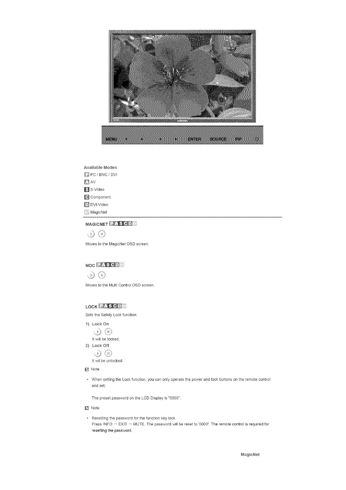
Availablei'_odes
_ PC/BNC /DVI
D S-Video
Component
DVI-Video
MagicNet
MAGICNET ;:::
.........!3¸
Moves to the MagicNet OSD screen
MDc
Moves to the Multi Control OSD screen.
LOCK
Sets the Safety Lock function.
1) Lock On
It will be locked.
2} Lock Off
It wil be unlocked
r_ Note
• When setting the Lock function, you can only operate the power and lock buttons on the remote control
and set.
The preset password on the LCD Display is "0000"
[] Note
Resetting the password for the function key bck
Press INFO _ EXiT _ MUTE. The password will be reset to '0000' The remote control is required for
resetting the password.
MagicNet

[] Note
Theoperating system for this set only supports English so the other languages might be corrupted on the
screen
For MagicNet, a remote control is available for MagicNet. However, it is recommended using a separate
USB keyboard
For MagicNet in Device mode, moving external devices while booting may cause errors. Set up external
devices only if the LCD Display turns on
Do not unplug the LAN cable used for the network (ex: video display). Otherwise, the program (MagicNet)
may stop If you do unplug the cable, restart the system
Do not unplug the LAN cable used by an USB device (ex: video display) Otherwise, the program
(MagicNet) may stop.
To access other sources, press the SOURCE button in MagicNet
The preset password for the LCD Display is "000000"
The server program's Power-On option works only if the LCD Display's power is completely shut off
Please make sure not to use the Power-On option when the LCD Display is in the process of shutting down
since this may cause system errors on the LCD Display
In the OSD image of MagicNet, Network mode is the same as Device.
When using MagicNet with the MagicNet Server Program: perform Network mode
When using MagicNet with the device directly connected to LCD Display : execute Device mode.
Photo
The JPEG, BMP file format ere supported.
1} Auto
Automatically fits the image to the window.
Orig r_al
Shows the properties of the odginal file.
2} Side Show
Displays the properties of the original fib as they are.
3} _terva
Controls the time intervals between image files for e slide show
(5 Sec. 10 Sec, 20 Sac. 30 Sec. 60 Sec)
4}Rotation
0
Displays an image fib by turning it clockwise by 90 degrees
5) Zoom
Displays a reduced picture.
6) Close
Closes the image control Menu
Music
The MP3 file format is supported
Movie
The MPEG1, WMV file format are supported
1) P}ay
Plays a movie file.
2} FuI_Size
Plays a movie file in full screen.
OFFICE tHTML
,_j;'
PPT(Power Point), DOC{MS Word), ×kS(MS Excel), PDF, HTML, HTM flies are displayed.
* Install the proper viewer(freeware) program to see the MS Offme(Word, Excel, Power Point) or PDF
doucuments
interact
.....:P
Connects to the Internet
Setup
Sets various functions in MagicNet mode
A password must be entered to access Setup mode
1} Schedule View
Displays a schedule.
2} TCP/UP
Changes the TCP/IP settings
3} Connection
Modifies the network settings
4) Password
The password can be changed.
• The password should be between 6 and 12 characters in numeric format
(You should enter a password between 6 and 12 characters in numeric format)
• If you enter the wrong password three times, the setup configuration is reset and a warning message
appears from the server
• If you forget the password, enter Info, 8, 2 and 4 on the remote control to initialize the password. This
willresettheprevioussettingsofSetupmode
5} File
Local:Youcandeleteorcopyfliesonbothlocalandremovabledisks.
6} PlayOption
:,>
You can set the repeat play and screen settings.
Repeat : Determines the repeat option for playing movies and music
• None -Select No Repeat to play a movie or tune in the list only once.
• File Repeat - Select Repeat File to play a movie or tune in the list repeatedly
List Repeat -Select Repeat List to play movies or tunes in the list in sequence repeatedly.
Rotation -Sets the picture orientation.
• Landscape -Sets the screen resolution to 1366x768 pixels
Portrait -Sets the screen resolution to 768x1366 pixels
EWF(Enhanced Write Filter) : Prevents change to and loss of the data saved on the disk.
• Disable -Disables EWF to allow saved data to be changed data on the protected disk (drive C:) When
switching from the Enable to the Disable state, you can select Commit.
Enable -Enables EWF to prevent saved data to be changed on the protected disk (drive C:).
• Commit -Commit the changed data to the protected disk (drive C:) when EWF is in the Enable state
Commit is not available when EWF is in the Disable state.
[] Notice
• It is highly recommended not to turn off the AC power dudng an operation.
[] Note
• For pivoted monitors, ticker transparency is not supported.
• For pivoted monitors, a screen resolution of up to 720"480(SD) is supported for movies.
[] Note
For drive D:, EWF is not applied
When the contents of Setup have been changed when EWF is in the Enable state, to save the changes in
the disk, you must Commit them.
By selecting Disable, Enable or Commit, the system is restarted
© 1995-_2007 SAMSUNG ALL Right Reserved
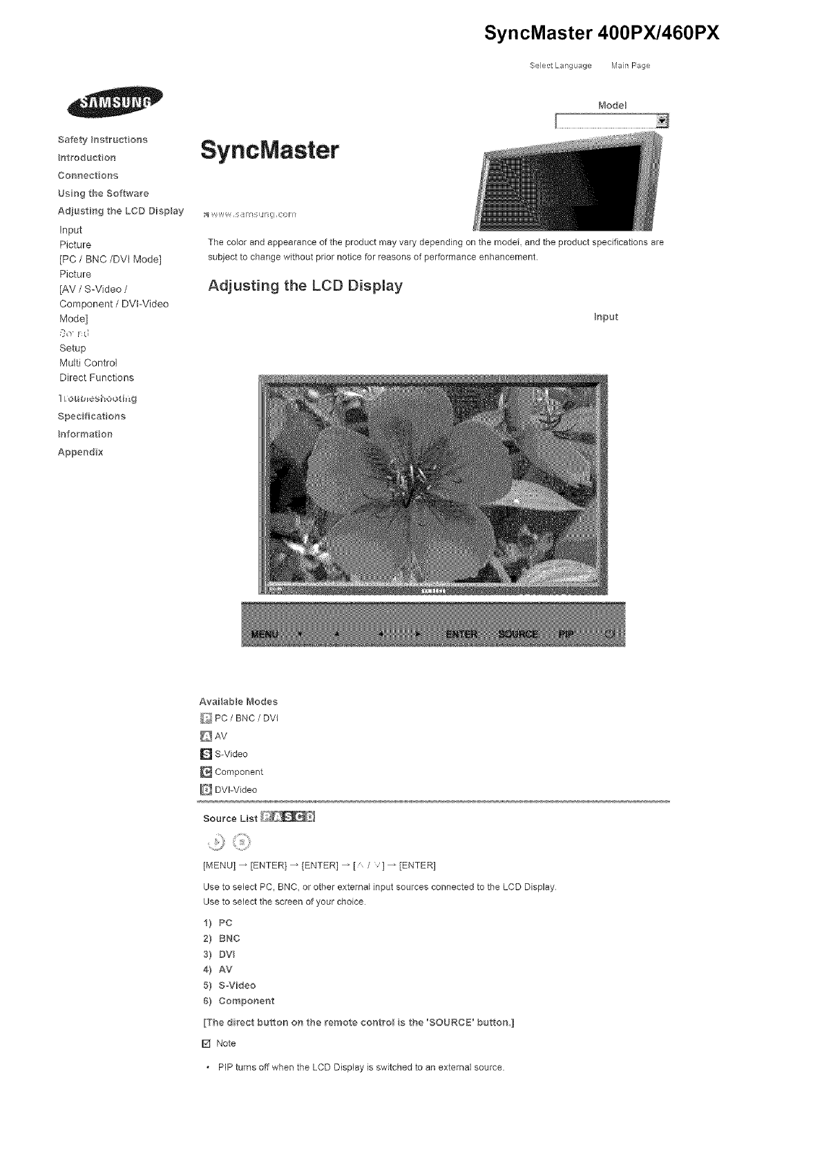
Safety }nstruct ona
ntroductioe
Connect ons
Usng the Software
Adjust#_ 9 the LCD Display
Input
Picture
[PC /BNC/DVI Mode]
Picture
[AV /S-Video /
Component /DVFVideo
Mode]
So !:d
Setup
Multi Control
Direct Functions
Lou_es_ ooti_g
Spec ficat orrs
eformat on
Append x
SyncMaster
SyncMaster 400PX/460PX
._electLang _age Man Page
t_'_odel
:_ V W,,W_, ,_/I_M Fli I ,ionl
The color and appearance of the product may vary depending on the model, and the product spedflcations are
subject to change without prior notice for reasons of performance enhancement.
Adjusting the LCD Display
Input
AvaHab e Modes
_ PC /BNC /DVI
DAv
[] S-Video
[] Component
[] DVPVideo
Source List
[MENU] _ [ENTER] _ [ENTER] _ [ / '1 _ [ENTER]
Use to select PC, BNC, or other external input sources connected to the LCD Display
Use to select the screen of your choice
i) PC
2} raNG
s) mv
4) AV
5) SWideo
6) Component
[The direct button on the remote contro_ a the 'SOURCE' button ]
[] Note
. PIP turns off when the LCD Display is switched to an external source.
PIP
When external A/V devices such as VCRs or DVDs are connected to the LCD Display, PIP allows you to watch
video from those devices in a small window super-imposed on the PC Video signal (Off/On)
[] Note
• More than one PIP cannot be overlapped on screen as BNC and the component use the same terminal
[MENU] _ [ENTER] _ [' /,] _ [ENTER] _ [ENTER l _ [' /"l _ [ENTER]
Turns the PIP Screen Off/On.
- Off
- On
[The direct button on the remote contro is the qsq?' button,]
2] Source
[MENU] _ [ENTER] _ [" /,] _ [ENTER l _ [' /,] _ [ENTER l _ [' /l _ [ENTERI
Selects the input source for the PIP
- PC : AV /S-Video /Component Mode
- BNC : AV/S-Video Mode
- DVI : AV /S-Video /Component Mode
- AV /S-Video : PC /BNC /DVI Mode
- Component : PC /DVl Mode
[The direct button on the remote contro is the o _ R,t_ buttol'L]
3} Swap
[MENU] _ [ENTER] _ [' /,]_[ENTER]_[' /,]_[ENTER]
Swaps the contents of the PIP and main image
The image in the PIP window will appear on the main screen, and the main screen image will appear in the
PIP window
[The direct button on the remote contro is the 'SW/_IP" burton'L]
4) Size
[MENU] _ [ENTER] _ [,'I,] _ [ENTER l_ [' I,] _ [ENTER l_ [' ] _ [ENTER]
Changes theSizeofthePIP window
[The direct button on the Fern/ore contro is the 'S 7t:' button,]
5] Position
.....P
[MENU] _ [ENTER 1_ [ /,] _ [ENTER l _ [' /,] _ [ENTER l _ [' l _ [ENTER]
Changes the Posilon of the PIP window
6] Tra_'_sparency
[MENU] _ [ENTER 1_ [ /,] _ [ENTER l _ [' /,] _ [ENTER l _ [" l _ [ENTER]
Adjusts the Transparency of PIP windows
-High
-Medium
-Low
-Opaque
r_ Note
• If you select ilii_ _ in Size Position and Transparency wiI not be activated.
Available Modes: PIP ON
Edit Name
[MENU] _ [ENTER] _ 1' /] _ ]ENTER] _ { /l _ {ENTER] _ [ /] _ [ENTER l
Name the input device connected to the input jacks to make your input source selection easier
I) PC
2) BNC
3) DV
4) AV
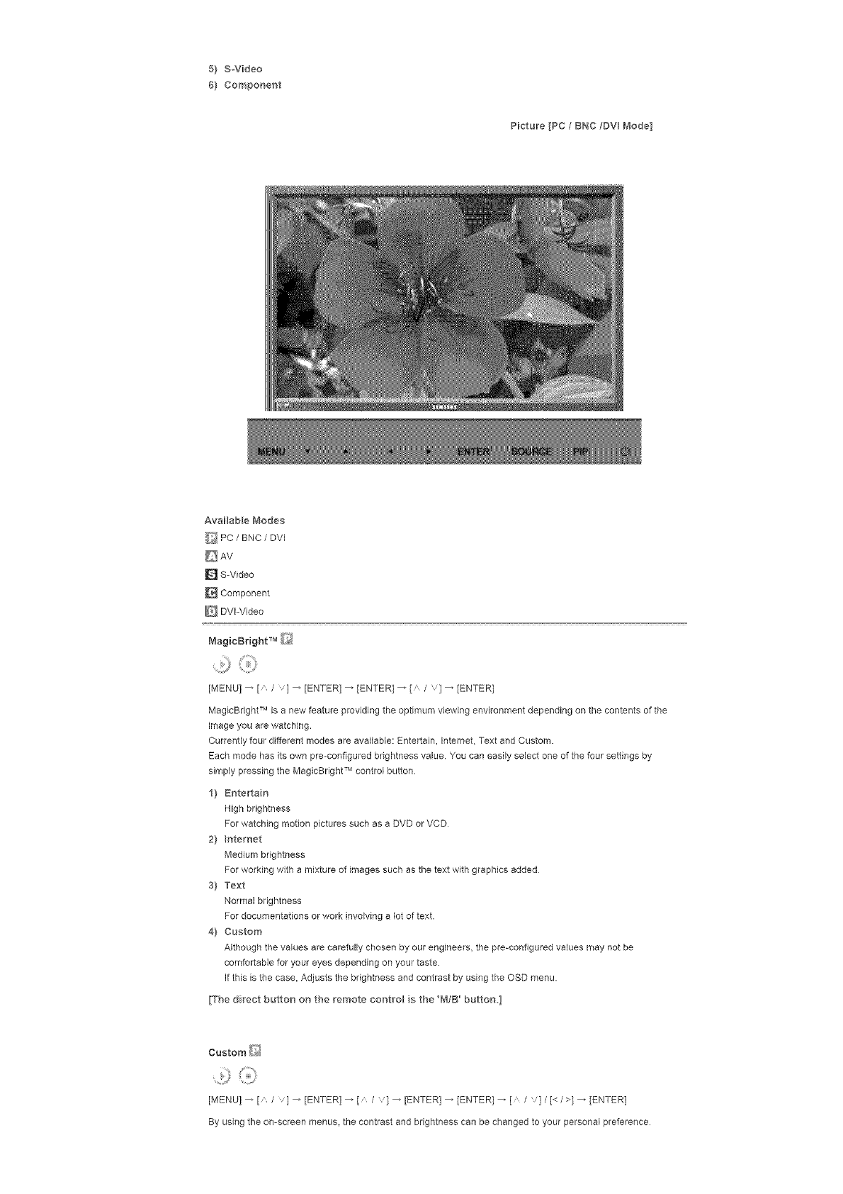
5! S-Video
6! Component
Picture [PC /BNC/DVI Mode]
Availab e Modes
_:_ PC /BNC /DVI
D AV
D S-Video
Component
DVl-Video
[MENU] _ [ /V] _ [ENTER] _ [ENTER] _ [ /v] _ [ENTER]
MagicBright TM is a new feature providing the optimum viewing environment depending on the contents of the
image you are watching,
Currently four different modes are available: Entertain, Internet Text and Custom,
Each mode has its own pre-configured brightness value, You can easily select one of the four settings by
simply pressing the MagicBright TM control button
1! Entertain
High brightness
For watching motion pictures such asaDVD or VCD
21 nternet
Medium brightness
For working with a mixture of images such as the text with graphics added
3! Text
Normal brightness
For documentations or work involving a lot of text.
4! Custom
Although the values are carefully chosen by our engineers, the pre-configured values may not be
comfortable for your eyes depending on your taste.
If this is the case, Adjusts the brightness and contrast by using the OSD menu.
[The direct button on the remote control s the 'M/B' button I
Custom _'>_
[MENU] _ [n /v] _ [ENTER] _ [n /,] _ [ENTER] _ [ENTER] _ [ Iv]/[< I>]_ [ENTER]
By using the on-screen menus, the contrast and brightness can be changed to your personal preference
1}Contrast
AdjuststheContrast.
2}Brightneas
AdjuststheBrightness.
[] Note
• ByadjustingthepictureusingtheCustomfunction,MagicBdghtwillchangetoCustommode.
ColorTone_
[MENU]_ [ /l _ [ENTER] _ [ / '1 _ [ENTER] _ [ / '1 _ [ENTER]
The color tones can be changed
1) Cool
2} Norma_
3} Warm
4} Custom
(Ava lable in PC, BNC mode on_y}
Color Control Q
......jj
[MENU] _ [' /'l _ [ENTER] _ [ /'1 _ [ENTER] _ [ENTER 1_ [< />l _ [ENTER]
Adiusts the individual R, G, B color controls
(Available in PC, BNC mode only]
1} Red
2) Green
3} Blue
[] Note
• If you adjust the picture by using the Custom function, Color Tone will turn to the Cusome mode.
image Lock is used to fine-tune and get the best image by removing noise that creates unstable images with
jitters and shakiness, if satisfactory results are not obtained using the Fine adjustment, use the Coarse
adjustment and then use Fine again
(Available in PC, BNC mode only]
1} Coarse
.........H}
[MENU l_ [' /] _ [ENTER] _ [' /] _ [ENTER] _ [ENTER] _ [</>l_ [ENTER]
Removes noise such as vertical stripes. Coarse adjustment may move the screen image area. You may
relocate it to the center using the horizontal control menu.
2} Fine
[MENU l _ [n /] _ [ENTER] _ [' /] _ [ENTERI _ [" /] _[ENTER] _ [< />1 _ [ENTER]
Removes noise such as horizontal stripes. If the noise persists even after fine tuning, repeat it after
adjusting the frequency (clock speed).
3} Position
[MENU l _ [ /] _ [ENTER 1_ [a /l _ [ENTER1 _ [ /l _[ENTER] _ [< />1/[ /]_
]ENTER]
Adjusts the screen location horizontally and vertically
Auto Adjustment _
[MENU]_ [ /v] _ [ENTER] _ [ /v] _ [ENTER]
The values of Fine, Coarse, Position are adjusted automatically.
By changing the resolution in the control panel, the auto function is performed
(Available in PC, BNC mode only)
[The direct button on the remote control s the "AUTO button,]
Signal Balance _[i_
TNS is used to make up for the weak RGB signal transmitted by a long signal cable
[Available in PC, BNC mode only]
1} Signal Balance
[Kf_ENUl _ ['_ /] _ [ENTER 1_ {'_ /] _ {ENTER 1_ ]ENTER] _ [" / '1 _ [ENTER]
Selects either On or Off with the signal control
2} Sgna Control
[MENUI _ [" /] _ [ENTER1 _ [" /] _ [ENTERI _ [" /'l _ [ENTERI _ [" /'] _ [ENTER1
[/,] _ [< />] _ [ENTER]
Adjusts the R Phase, G Phase, B Phase, Gain and Sharpness manually
Size _]_
......,,jj
[MENU] _ [ /"l _ [ENTERI _ [ / '1 _ [ENTER] _ [ / '1 _ [ENTER]
The Size can be switched
I) 16:9
2} 4:3
PIP Picture [/_
.....u
[MENU] _ [" /"l _ [ENTER] _ [ / '1 _ [ENTER] _ [" / '1 _ [ENTER] _ [," /,] _ [ENTER l _ [," /
'] _ [ENTER] _ [< />] _ [ENTER]
Adjusts the PIP Screen Settings.
1) Contrast
Adjusts the Contrast of the PIP window on the screen
2} Brightness
Adjusts the Brightness of the PIP window on the screen.
3} Sharpness
Adjusts the difference between the lightest and darkest areas of the PIP window
4} Co,or
Adjusts the Color of the PIP window on the screen
5} Tint
Adds a natural tone to the PIP window.
You can view a picture from AV, SoVideo through the PIP screen in PC, BNC and DVl (PC) mode,
Operates only if the video signal is NTSC,
AvailabBe Modes: PIP ON
Picture [ AV /S-Video /Component /DV -Video Mode]

AvailableI'_1odes
_ PC/BNC /DVI
AV
D S-Video
Component
E_ DVI-Video
B,lode
[MENU] _ [' / 'l _ [ENTER] _ [ENTER 1_ [ /l _ [ENTER1
The LCD Display has four automatic picture settings ("Dynamic", "Standard", "Movie" and "Custom") that are
preset at the factory.
Dynamic, Standard, Movie, or Custom can be activated
1) Dynamic
2} Standard
3} _,lovie
4} Custom
[The direct button oH the remote eoHt_'ol s the 'P.MODE' buttoH.]
Custom
[MENU l _ [a /l _ [ENTER] _ [a / ,1 _ [ENTER] _ [a / ,1 _ [ENTER] _ [< />1 _ [ENTER]
By using the on-screen menus, the contrast and brightness can be changed to your personal preference
1} Cor_trast
Adds a natural tone to the PIP window
2} Brightness
Adjusts the Brightness.
3} Sharpness
Adjusts the picture Sharpness
4} Cobr
Adjusts the picture Color
5} Tint
Adds a natural tone to the display
Operates only for AV and SoVideo mode. Operates onJy if the video signal is NTSC.
Color Tone
P
[MENU]_[ /I_[ENTERI_[ / '}_[ENTER]_[ / '}_]ENTER]
The color tones can be changed The individual Color components are also user adjustable.
1) Cool 2
2) Coo 1
3} Normal
4} Warm1
5) Warm2
Size
[MENU] _ [" /,l _ [ENTER] _ [" /'1 _ [ENTER] _ [" /'1 _ [ENTER]
The Size can be switched
1) 16:9
2} Zoom 1
3) Zoom 2
4} 4:3
[The ZOO_7_1, ZOOM2 are not available n I080i (or over 720p} of DTV,]
Digital NR (Digital Noise Reduction)
[MENU] _ [" /"l _ [ENTER] _ [" / '1 _ [ENTER] _ [_ / '1 _ [ENTER]
Turns the Digital Noise Reduction feature Off/On
The Digital Noise Reduction feature allows you to enjoy clearer and crisper images.
1) Off
2} On
Film Mode
[MENU] _ [" /"l _ [ENTER] _ [" / '1 _ [ENTER] _ [" / '1 _ [ENTER]
Turns Film Mode Off/On.
The Film Mode feature offers you a theater-quality viewing experience
(Not available in DVloVideo Mode}
_) off
2} On
PIP Picture
[MENU] _ [" /"l _ [ENTER] _ [" / '1 _ [ENTER] _ [" / '1 _ [ENTER] _ [" /,] _ [ENTER l _[< />l
[ENTER]
Adjusts the PiP Screen Settings
1} Contrast
Adjusts the Contrast of the PIP window on the screen
2} Brightness
Adjusts the Brightness of the PIP window on the screen
AvailabBe Modes: PIP ON
Sound

Available{'_ode s
_ PC /BNC /DVI
AV
D S-Video
Component
E_ DVI-Video
Mode
[MENU] _ [' / 'l _ [ENTER] _ [ENTER] _ [ /l _ [ENTER1
The LCD Display has a built-in high fidelity stereo amplifier.
1} Standard
Selects Standard for the standard factory settings.
2} Music
Selects Music when watching music videos or concerts
3} Movie
Selects Movie when viewing movies
4} Speech
Selects Speech when watching a show that is mostly dialogue (i.e, news)
5} Custom
Selects Custom if you want to Adjusts the settings according to your personal preferences
Custom
....,0G>
[MENU] _ [_ /v] _ [ENTER] _ [' / ,] _ [ENTER] _ [' /v] _ [ENTER] _ [< />] _ [ENTER]
The sound settings can be adjusted to suit your your personal preferences.
1} Bass
Emphasizes low frequency audio
2} Treble
Emphasizes high frequency audio
3} BaBance
Allows you to Adjusts the sound balance between the left and right speakers.
[You can hear the sound even when sound value s set to 0]
[] Note
•If you adjust picture using Sound Custom function, Sound Mode will turn to Custom mode
Auto Volume
.......2}¸<:iiii}
[MENU] _ [ /v] _ [ENTER] _ [ /v] _ [ENTER] _ [ /v] _ ]ENTER]
Reduces the difference in volume control between broadcasters
9 off
2} On
SRS TSXT
[MENU] _ [ /l _ [ENTERI _ [ / '1 _ [ENTER] _ [ / '1 _ [ENTER]
SRS TSXT is a patented SRS technology that solves the problem of playing 51 multichannel content over two
speakers. TruSurround delivers a compelling, virtual surround sound experience through any two-speaker
playback system, including internal television speakers.
It is fully compatible with all multichannel formats
9off
2} On
[The direct button on the remote control s the 'SRS' button,]
Sound Select
[MENU] _ [" /"l _ [ENTERI _ [" / '1 _ [ENTER] _ [" / '1 _ [ENTER]
Selects either Main or Sub when PIP is Qn
2) Sub
[Available Modes: P_P ON]
Setup
Available Modes
_ PC /BNC /DVl
AV
D S-Video
Component
DVI-Video
.......2}¸<iiii}
[MENU] _ [ /v] _ [ENTER] _ ]ENTER] _ [ /v] _ ]ENTER]
You can choose from 11 languages.
[] Note
• The language chosen affects only the language of the OSD
It has no effect on any software running on the computer
* Enqliah_ Deutsch, EspaSol, F_'an_:ais, ffaliano, Svenska, B ;_,
dpm_ PyccK_, _0t, Portugu_s
Time
Se{ects from one of 4 time settings, Clock Set, Sleep Timer, On Timer, and Off Timer.
1) Clock Set
[MENU l _ [A /] _ [ENTER] _ [a /] _ ]ENTER] _ ]ENTER] 4 [< />l _ [ENTERI
Current Time Setting.
2} Seep Timer
[MENU l _ [ /] _ [ENTER] _ [' /] _ tENTER 1_ [ /] _ [ENTERI 4[< />1 4 [ /]
[ENTER] 4[< />] _ [,, /v] _ [ENTER[
Turns the LCD Display off automatically at certain times (Off, 30, 60, 90, 120, 150, 180)
3} On Timer
[MENU] _ [A /] _ [ENTER] _ [A /] _ [ENTER] _ [a I] _ [ENTER] 4 [<I>1_ [a /'l
]ENTER]
Turns the LCD Dbplay on automatically at a preset time
Controls the mode and the volume level at the time the LCD Display turns on automatically
4} Off Truer
........,j, .............
[MENU l _ [a /] _ [ENTER] _ [a /] _ ]ENTER] _ [ /] _ [ENTERI 4[< />1 4 [ /]
]ENTER]
Turns the LCD Display off automatically at a preset time
[] Note
When selecting Yes for the On Timer or Off Timer when the Clock is not set up, a guiding message pops
up: "Set the clock first.".
[MENU] _ [A /v] _ [ENTER] _ [A /v] _ [ENTER] _ [ /v] 4 ]ENTER]
Changes the opaqueness of the OSD background
f) Hgh
2} _'_edium
3) Low
4} Opaque
Safety Lock PIN
[MENU] _ [" /,l _ [ENTER] _ [" /'1 _ [ENTER] _ [O_-9l_ [0~91 _ [0~9]
The password can be changed
[MENU] _ [" /,] _ [ENTER] _ [" / '] _ [ENTER] _ [" / '] 4 ]ENTER] _ [MENU]
Thepictureparametersarereplacedwiththefactorydefaultvalues
f) On
2) off
Video Wall
A Video Wall is a set of video screens connected together, so that each screen shows a part of the whole
picture or where the same picture is repeated on each screen
When the Video Wall is on, you can adjust the Video Wall screen setting.
f) Video Wall
)MENU] _ [,' /] _ [ENTER) _ [" /] _ [ENTER] _ [ENTER] _ [ /'] _ )ENTER]
Turns Off/On the Video Wall function of the selected display Off/On
- Off
- On
2} Format
[MENU l _ [" /'] _ [ENTER) _ [" /] _ [ENTER] _ [ /,] _[ENTER] _ [" / 'l _ [ENTER]
The format can be selected to see a divided screen
-FuI
Provides a full screen without any margins.
- Natural
Displays a natural image with the original aspect ratio intact
3) ScreeH Divider
......j
[MENU l _ [' /] _ [ENTER] _ [' /] _ )ENTER] _ [ /,1 _ [ENTER l _ [ /,] _ [ENTER l
The screen can be divided into several images.
A number of screens can be selected with a different layout when dividing.
Select a mode in Screen Divider.
Select a display in Display Selection.
The selection will be set up by pressing a number in the selected mode
2×2
3×3
4×4
5×5
1×2
2×I
1x5
5×I
I_ Note
. When Video Wall is running, the PiP, Auto Adjustment, Image Lock, and Size functions are not available.
Launching Video Wall while PIP is running, will switch PiP Off. Video Wall does not operate in MagicNet
mode.
Safety Screen
The Safety Screen function is used to prevent afterimages that may appear when a still picture is displayed on
the screen over a long time
- The Screen Scroll function scrolls the screen for the specified period of time
- This function is not available when the power is turned off
f) SafetyScreen
[MENU l _ [' /] _ [ENTER 1_ [' /] _ [ENTER] _ [ENTER] _ [ /,1 _ [ENTER]
Determines whether to turn the Screen Scroll function Off or Qn
- Off
- On
2} Hte_va
,)
[MENU l _ [' /] _ [ENTER] _ [' /'1 _ [ENTER 1_ [ /,1_ [ENTER l _[ /,1 _ [ENTER]
Determines the time interval to run the Screen Scroll operation. (1-10 Hour)
The tme is calculated on the basis of the power on time
By default, the time is set to 10 hours
-1_10 Hour
3} Second
.......:,j
[MENU] _ [a /] _ [ENTER] _ [' /] _ [ENTER] _ [ I]_ [ENTER] _ [a / '1 _ [ENTER]
Determines the time period to run the Screen Scroll operation. (1-5 Second)
By default, the time is set to 5 seconds
- Type+Scroll : I~5 Second
- Type°Pi×eL Bar Eraser : 10-+50 Second
4) Type
......,,J
[MENUI _ [' /] _ [ENTERI _ [ /l _ rENTER1 _ [ /l _ [ENTERI _ [ /] _ rENTER1
You can change the Safety Screen Type.
+ Scroll
-Pxel
-Bar
-Eroser
Resolution Select _
+)
[MENU] _ [a /] _ [ENTER] _ [o /,1 _ [ENTER] _ [o I '1_ [ENTER]
When the picture is not displayed properly on the screen when setting the graphics card resolution of the
computer to 1024 x 768 @ 60Hz, 1280 x 768 @ 60Hz, 1360 x 768 @ 60Hz or 1366 x768 @ 60Hz, by using
this function(Resolution Select), you can have the picture displayed on the screen in the specified resolution
Available in PCIBNC mode only
i) off
2} I024X 768
3} I280 X 7'68
4} 1360 X 768
5} 1366 X 768
[] Note
. Selecting the menu is only allowed when the graphics resolution is set to 1024 x 768 @ 60Hz, 1280 x 768
@ 60Hz, 1360 x 768 @ 60Ha or 1366 x768 @ 60Hz
Lamp Control [_
[MENU] _ [" /"l _ [ENTER] _ [" / '1 _ [ENTER] _ [ENTER] _ [< />l _ rENTER1
Adjusts the inverter lamp in order to reduce energy consumption
Power On Adjustment +_
[MENU] _ [ /"l _ [ENTER] _ [ / '1 _ [ENTER] _ [ENTER 1_ [' /,]_ rENTER 1
Adiusts the Power On time for the screen.
_Ca_t o_: Set the Power O¢_dine e _e Ioger to avoid ove_+vo tage
Reset
The picture parameters are replaced with the factory default values
1} Image Reset [:_
[MENU] _ [" /] _ [ENTER] _ [" /] _ [ENTER] _ [ENTER] _ [< />]_ [ENTER]
Available in PC/BNC mode onUy
2} Co,or Reset _
..........0
[MENUI _ ['_ /] _ [ENTERI _ ['_ /l _ [ENTERI _ [ / 'l _ [ENTERI _ [< />14 [ENTER]
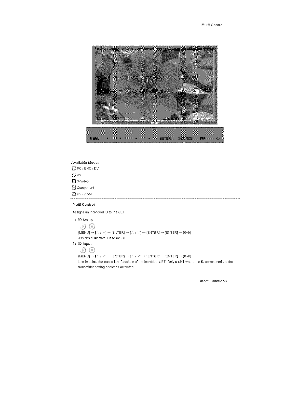
MutiCoot_o
AvailabeModes
_ PC/BNC /DVI
D AV
D S-Video
Component
_ DVI-Video
Multi Control
Assigns an individual ID to the SET
1) D Setup
[MENU l _ [, /] _ [ENTER 1_ [a /] _ [ENTER1 _ [ENTER] _ [0_-91
Assigns distinctive IDs to the SET.
2} D _oput
..........:9
[MENU] _ [' /'] _ [ENTER 1_ [a /'1 _ [ENTER 1_ [ENTER] _ [0--91
Use to select the transmitter functions of the individual SET Only a SET where the ID corresponds to the
transmitter setting becomes activated
Direct Funet ons
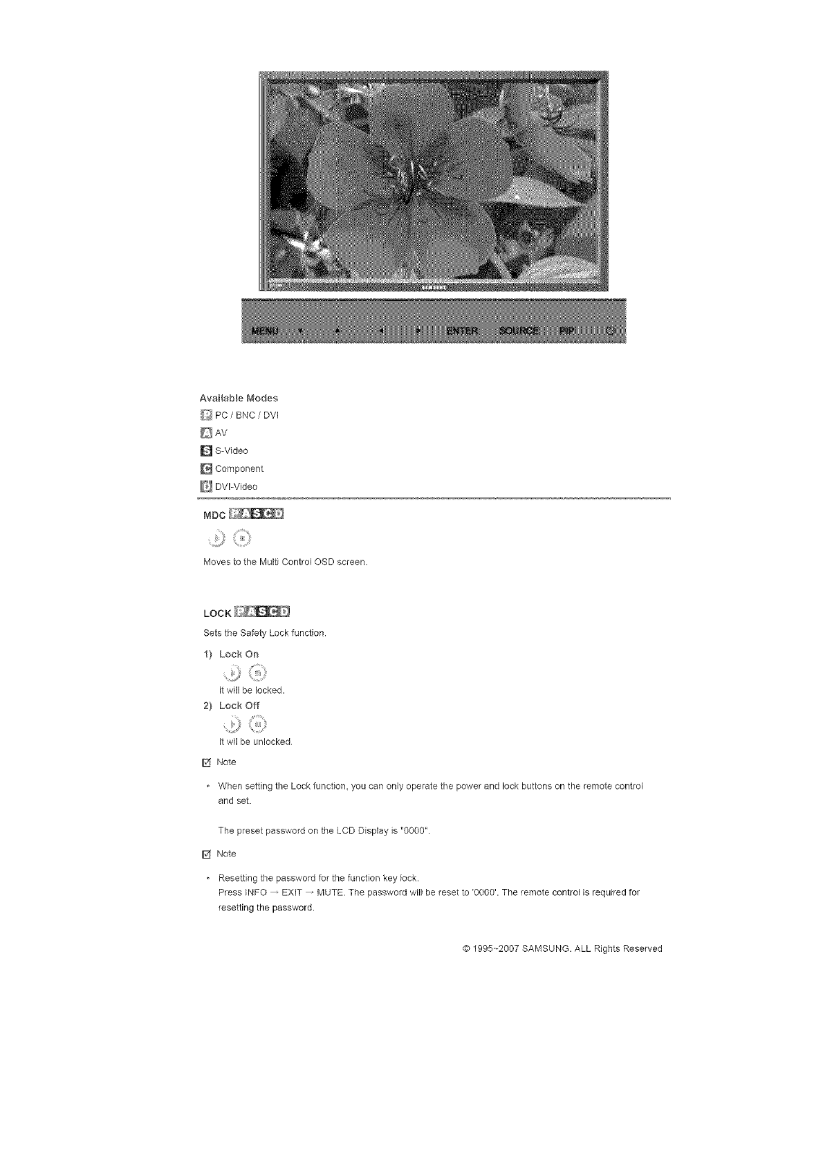
Availablei'_odes
_ PC/BNC /DVI
D S-Video
Component
E_ DVI-Video
MDC
0
Moves to the Multi Control OSD screen.
LOCK
Sets the Safety Lock function.
1) Lock On
it will be locked.
2} Lock Off
Jt wil be unlocked
[] Note
• When setting the Lock function, you can only operate the power and lock buttons on the remote control
and set.
The preset password on the LCD Display is "000O".
[] Note
• Resetting the password for the function key lock.
Press _NFO _ EXIT _ MUTE. The password will be reset to '0000'. The remote control is required for
resetting the password.
© 1995~2007 SAMSUNG. ALL Rights Reserved
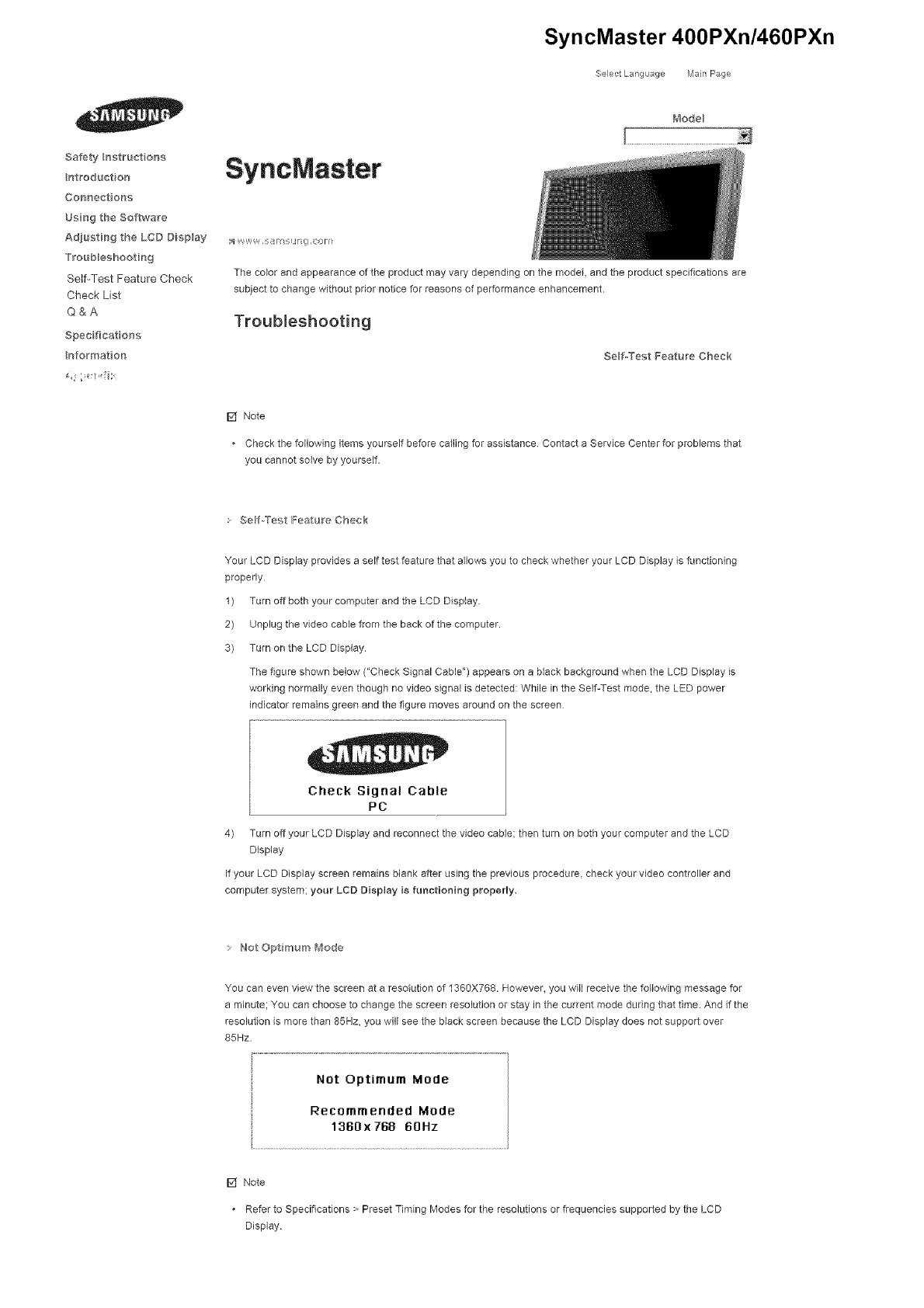
SyncMaster 400PXn/460PXn
._SelectLang _age IVlan Page
Safety _ngtruct on5
ntroduct on
Cormect ons
Ugn9 the Softwa_'e
Ad_usti_g the LCD Digplay
TFoub_eshooting
Self-Test Feature Check
Check List
Q&A
Spec ficat o_s
Informat on
SyncMaster
t_'_odeB
;_ V_y,,W_ ,i OFII
The co,or and appearance of the product may vary depending on the model and the product specifications are
subject to change without prior notice for reasons of performance enhancement.
Troubleshooting
Self-Test Feature Check
[] Note
Check the following items yourself before calling for assistance Contact a Service Center for problems that
you cannot solve by yourself.
Self._Tef-,t Feature Check
Your LCD Display provides a self test feature that allows you to check whether your LCD Display is functioning
properly
1) Turn off both your computer and the LCD Display.
2) Unplug the video cable from the back of the computer.
3) Turn on the LCD Display.
The figure shown below ("Check Signal Cable") appears on a black background when the LCD Display is
working normally even though no video signal is detected: While in the Self-Test mode. the LED power
indicator remains green and the figure moves around on the screen
Check Signal Cable
PC
4) Turn off your LCD Display and reconnect the video cable: then turn on both your computer and the LCD
Display
If your LCD Display screen remains blank after using the previous procedure, check your video controller and
computer system; your LCD Display is functioning property.
Not Opt mum _ode
You can even view the screen at a resolution of 1360X768. However. you will receive the following message for
a minute; You can choose to change the screen resolution or stay in the current mode during that time. And if the
resolution is more than 85Hz. you will see the black screen because the LCD Display does not support over
85Hz.
Not Optimum Mode
Recommended Mode
1360x 768 60Hz
[] Note
Refer to Specifications > Preset Timing Modes for the resolutions or frequencies supported by the LCD
Display
IblaH_te_alr_cearidCba,__@
MaintainingtheLCDDisplayCase
Cleanwithasoftc}othafterdisconnectingthepowercord
* Donotusebenzene,thinnerorotherflammablesubstances,ora
wetcloth.
* WerecommendthataSamsungcleansingagentisusedtoprevent
damagetothescreen
2) Maintaining the Flat Panel Display Screen.
Clean with a soft cloth (cotton flannel) smoothly
* Never use acetone, benzene or thinner
(They may cause flaws or deformation of the screen surface)
The user will be required to pay costs and related expenses for
repairing damages caused
Symptoms aired Recomme_}ded Act oras
ISff Note
A LCD Display recreates visual signals received from the computer. Therefore, if there is a probbm with
the corcputer or the video card_ this can cause the LCD Display to become blank, have poor coloring,
become noisy_ and video mode not supported, etc In this ease, first check the source of the problem, and
then contact a Service Center or your dealer
1) Check if the power cord and the video cables are properly connected to the computer
2) Check if the computer beeps more than 3 times when booting.
(If it does, request an a service for the main board of the computer.)
3) If you installed a new video card or if you assembbd the PC, check if you installed the Adaptor(video)
4) Check if the scanning ratio of the video screen is set to between 50 Hz ~ 85 Hz
(Do not exceed 60Hz when using the maximum resolution.)
5) If you have problems in installing the Adaptor (video) driver, boot the computer in Safe Mode, remove the
Display Adaptor in the "Control Panel, System, Device Administrator" and then reboot the computer to
reinstall the Adaptor (video) driver
Cheek Lat
[] Note
• The following table lists possible problems and their solutions Before calling for assistance, check the
information in this section to see if you can remedy any problems for yourself. If you do need assistance,
please call the phone number on the Information section or contact your dealer
• For more network-related information, refer to the MagicNet Troubleshooting section
• P_'obem Ire ated to _he r_sta_ a_io_'1(PC _ode)
[] Note
• Problems related to the LCD Display installation and their solutions are listed.
Problems Solutio_'_s
Check if the signal cable between the computer and the LCD
TheLCDDispayscreenflickers, Displayissecurelyconnected.
(RefertoConnectingtoaComputer)
: P_oberosire#arealtoH'_eScreen
[] Note
. ProblemsrelatedtotheLCDDisplayscreenandtheirsolutionsarelisted
Problems
Thescreenisblankandthepower
indcators off,
'CheckSigna_CabBe"message,
_NotOptmumMode_message
Thepctureroilsvertically,
Theimageisnotdear;pictures
b_urred,
ThepctureimageisunstabBeand
shakes,
Ghostimagesareshowninthe
picture,
Theimages toolightortoodark,
Thescreencootisinconsistent,
Thecootimages distortedby
darkshadows,
Thecootwhteispoor,
ThepowerIndicatorblinksgreen
Thescreenisblankandthepower
indicator_ightissteadygreenor
blinksevery05orI seconds,
Thescreenisblankandits
blinking,
o
o
o
Solutions
Ensure that the power cord is firmly connected and the LCD
LCD Display is on.
(Refer to the Connecting the LCD Display )
Ensure that the signal cable is firmly connected to the PC or
video sources
(Refer to the Connecting the LCD Display )
Ensure that the PC or video sources are turned on.
Check the maximum resolution and the frequency of the video
Adaptor.
Compare these values with the data in the Preset Timing Modes
Chart.
Check if the signal cable is securely connected.
Re-connect it, if necessary.
(Refer to Connecting to a Computer)
® Run Frequency Coarse and Fine tuning.
Turn on again after removing all accessories
(video extension cable, etc)
® Set the resolution and frequency to the recommended ranges.
Check if the resolution and frequency set for the computer video
card fails in the range supported by the LCD Display
If not, reset them referring to the current information under the
LCD Display menu and Preset Timing Modes
® Adjusts the brightness and contrast.
(Refer to the Brightness. Contrast)
® Adjust color using Custom under OSD Color Adjustment menu
The LCD Display is currently saving the changes made to the
settings to the OSD memory
® The LCD Display is using its power management system.
Press a key on the keyboard
If you see the "TEST GOOD" message on the screen when you
pressing the MENU button, check the cable connection between
the LCD Display and the computer to ensure that the connector
is properly connected
> P_ob eros ire ated to Audo
[] Note
,Problems related to audio signals and their solutions are listed below
NO SOUnd.
Problems Solutions
® Ensure that the audio came is firmly connected to both the
audioqn port on your LCD Display and the audio-out port on
your sound card.
(Refer to the Connecting the LCD Display )
® Check the volume level.
The sound eve s too low.
The sound s too high or too ow.
Check the volume level
If the volume is still too low after turning the control to its
maximum, check the volume control on the computer sound
card or software program.
Adjusts the Treble and Bass to the appropriate levels
,Probem re ated to _he Remote Control
[] Note
, Problems related to the remote control and their solutions are listed.
Probbms
The remote contro buttons do not
respond.
Solutions
® Check the polarities (+/-) of the batteries.
Check if the batteries are empty
® Check if the power is on.
Check if the power cord is securely connected.
® Check if a special fluorescent or neon lamp is on in the vicinity
"_ Prob eros lie ated to _agioNet
[] Note
• Making a Bootable USB Flash Disk.
Problems
Making a Bootabb USB Flash Disk
Solutions
You can turn a common 512-MB or bigger USB storage media
into a bootable disk using a USB bootable disk creation tool
(For example, the HP USB Disk Storage Format Tool)
2 Copies the OS ghost image and executables to your USB disk
3. Enter the BIOS menu of your set by pressing the F2 key in the
BIOS logo screen Then, enable the USB Boot First option by
selecting that option and pressing the Enter key in the Boot
menu.
4. Switch your set on while your USB disk is connected and boot
up in DOS mode.
5 Run C:\ghost exe and choose Local _ Partition _ From Image
from the menu. Choose the ghost image to update your USB
disk with and choose the target disk.
6 When the ghost image update finishes, the set will be rebooted
automatically.
Question
How can I change the frequency?
Q&A
Answe["
The frequency can be changed by reconfiguring the video card
Note that video card support can vary, depending on the version of
the driver used (Refer to the computer or the video card manual for
details.)
How can I Adjusts the reso ution? • Windows XP:
SettheresolutionintheControlPanel_ Appearanceand
Themes_ Display_Settings
WindowsME/2000:
SettheresolutionintheControlPanel_ Display_ Settings
*Contactthevideocardmanufacturerfordetails
HowcanIsetthePower Savng
fur_ct on?
Windows XP:
Set the resolution in the Control Panel _ Appearance and
Themes _ Display _ Screen Saver.
Set the function in the B{OS-SETUP of the computer. (Refer to
the Windows /Computer Manual)
® Windows ME/2000:
Set the resolution at the Control Panel _ Display _ Screen
Saver.
Set the function in the BIOS-SETUP of the computer (Refer to
the Windows /Computer Manual)
How can I c_ean the outer
case/LCD PaneB?
Disconnect the power cord and then clean the LCD Display with a soft
cloth, using either a cleaning solution or plain water
Do not leave any detergent or scratches on the case Do not let any
water enter the LCD Display
How can I pBay the video? The video supports the MPEG1 and WMV codecs only. Install the
corresponding codec to play the video Note that some of the codecs
can be incompatible
© 1995~2007 SAMSUNG. ALL Right Reserved

SyncMaster 400PX/460PX
._SelectLang _age IVlan Page
Safety _ngtruct on5
ntroduct on
Cormect ons
Ugn9 the Softwa_'e
Ad_usti_g the LCD Digplay
TFoub_eshooting
Self-Test Feature Check
Check List
Q&A
Spec ficat o_s
Informat on
SyncMaster
t_'_odeB
;_ V_y,,W_ ,i OFII
The co,or and appearance of the product may vary depending on the model and the product specifications are
subject to change without prior notice for reasons of performance enhancement.
Troubleshooting
Self-Test Feature Check
[] Note
Check the following items yourself before calling for assistance Contact a Service Center for problems that
you cannot solve by yourself.
Self._Tef-,t Feature Check
Your LCD Display provides a self test feature that allows you to check whether your LCD Display is functioning
properly
1) Turn off both your computer and the LCD Display.
2) Unplug the video cable from the back of the computer.
3) Turn on the LCD Display.
The figure shown below ("Check Signal Cable") appears on a black background when the LCD Display is
working normally even though no video signal is detected: While in the Self-Test mode. the LED power
indicator remains green and the figure moves around on the screen
Check Signal Cable
PC
4) Turn off your LCD Display and reconnect the video cable: then turn on both your computer and the LCD
Display
If your LCD Display screen remains blank after using the previous procedure, check your video controller and
computer system; your LCD Display is functioning property.
Not Opt mum _ode
You can even view the screen at a resolution of 1360X768. However. you will receive the following message for
a minute; You can choose to change the screen resolution or stay in the current mode during that time. And if the
resolution is more than 85Hz. you will see the black screen because the LCD Display does not support over
85Hz.
Not Optimum Mode
Recommended Mode
1360x 768 60Hz
[] Note
Refer to Specifications > Preset Timing Modes for the resolutions or frequencies supported by the LCD
Display
IblaH_te_alr_cearidCba,__@
MaintainingtheLCDDisplayCase
Cleanwithasoftc}othafterdisconnectingthepowercord
* Donotusebenzene,thinnerorotherflammablesubstances,ora
wetcloth.
* WerecommendthataSamsungcleansingagentisusedtoprevent
damagetothescreen
2) Maintaining the Flat Panel Display Screen.
Clean with a soft cloth (cotton flannel) smoothly
* Never use acetone, benzene or thinner
(They may cause flaws or deformation of the screen surface)
* The user will be required to pay costs and related expenses for
repairing damages caused
Symptoms aired Recomme_}ded Act oras
ISff Note
A LCD Display recreates visual signals received from the computer. Therefore, if there is a probbm with
the corcputer or the video card_ this can cause the LCD Display to become blank, have poor coloring,
become noisy_ and video mode not supported, etc In this ease, first check the source of the problem, and
then contact a Service Center or your dealer
1) Check if the power cord and the video cables are properly connected to the computer
2) Check if the computer beeps more than 3 times when booting.
(If it does, request an a service for the main board of the computer.)
3) If you installed a new video card or if you assembbd the PC, check if you installed the Adaptor(video)
4) Check if the scanning ratio of the video screen is set to between 50 Hz ~ 85 Hz
(Do not exceed 60Hz when using the maximum resolution.)
5) If you have problems in installing the Adaptor (video) driver, boot the computer in Safe Mode, remove the
Display Adaptor in the "Control Panel, System, Device Administrator" and then reboot the computer to
reinstall the Adaptor (video) driver
Cheek Lat
[] Note
The following table lists possible problems and their solutions Before calling for assistance, check the
information in this section to see if you can remedy any problems for yourself. If you do need assistance,
please call the phone number on the Information section or contact your dealer
P_'ob e_'ha ,eated to H'_e r_sta_ a_io_'1(PC _ode)
[] Note
• Problems related to the LCD Display installation and their solutions are listed.
Problems
The LCD Disp ay acreer_ flickers,
Solutio_s
® Check if the signal cable between the computer and the LCD
Display is securely connected.
(RefertoConnectingtoaComputer)
P_oberos iterated to _ll'_eScreen
[] Note
• Problems related to the LCD Display screen and their solutions are listed
Problems
The screen is blank and the power
ind cator s off.
'Check Signa_ CaMe" message.
"Not Opt mum Mode _ message.
The p cture roils vertically,
The image is not dear; picture s
Marred.
The p eture image is unstable and
shakes.
Ghost images are shown in the
picture.
The image s too light or too dark.
The screen color is inconsistent.
The coot image is distorted by
dark shadows.
The eoor whte is poor.
The power Indicator blinks green
The screen is blank and the power
indicator _ight is steady green or
blinks every 05 or I seconds.
The screen is blank and it s
blinking.
Solutions
Ensure that the power cord is firmly connected and the LCD
LCD Display is on.
(Refer to the Connecting the LCD Display )
Ensure that the signal cable is firmly connected to the PC or
video sources
(Refer to the Connecting the LCD Display )
Ensure that the PC or video sources ere turned on.
Check the maximum resolution end the frequency of the video
Adaptor.
Compare these values with the data in the Preset Timing Modes
Chart.
Check if the signal cable is securely connected.
Re-connect it, if necessary.
(Refer to Connecting to a Computer)
Run Frequency Coarse end Fine tuning.
® Turn on again after removing all accessories
(video extension cable, etc)
® Set the resolution end frequency to the recommended ranges.
Check if the resolution and frequency set for the computer video
card falls in the range supported by the LCD Display
If not, reset them referring to the current Information under the
LCD Display menu and Preset Timing Modes
Adjusts the brightness and contrast.
(Refer to the Brightness. Contrast)
Adjust color using Custom under OSD Color Adjustment menu
® The LCD Display is currently saving the changes made to the
settings to the OSD memory.
The LCD Display is using its power management system.
® Press a key on the keyboard
If you see the "TEST GOOD" message on the screen when you
pressing the MENU button, check the cable connection between
the LCD Display end the computer to ensure that the connector
is properly connected
: P_obems ,e a_ed to Audo
[] Note
,Problems related to audio signals and their solutions are listed below
NO SOUnd.
Problems Solutions
® Ensure that the audio came is firmly connected to both the
audioqn port on your LCD Display and the aud©-out port on
your sound card.
(Refer to the Connecting the LCD Display )
® Check the volume level.
The sound eve s too low.
The sound s too high or too ow.
Check the volume level
If the volume is still too low after turning the control to its
maximum, check the volume control on the computer sound
card or software program.
Adjusts the Treble and Bass to the appropriate levels
,Probem re ated to _he Remote Control
I_ Note
, Problems related to the remote control and their solutions are listed.
Probbms
The remote contro buttons do not
respond.
Solutions
® Check the polarities (+/-) of the batteries.
Check if the batteries are empty
® Check if the power is on.
Check if the power cord is securely connected.
® Check if a special fluorescent or neon lamp is on in the vicinity
Quest on
How can [change the frequency?
How can [Adjusts the reso ution?
How can [set the Power Savng
funct on?
How can [ c}ean the outer
case/LCD PaneB?
Q&A
Answer
The frequency can be changed by reconfiguring the video card
Note that video card support can vary, depending on the version of
the driver used (Refer to the computer or the video card manual for
details)
Windows XP:
Set the resolution in the Control Panel _ Appearance and
Themes _ Display _ Settings
® Windows ME/2000:
Set the resolution in the Control Panel _ Display _ Settings
* Contact the video card manufacturer for details
® Windows XP:
Set the resolution in the Control Panel _ Appearance and
Themes _ Display _ Screen Saver.
Set the function in the B{OS-SETUP of the computer. (Refer to
the Windows /Computer Manual)
® Windows ME/200O:
Set the resolution at the Control Panel _ Display _ Screen
Saver.
Set the function in the BIOS-SETUP of the computer (Refer to
the Windows /Computer Manual)
Disconnect the power cord and then clean the LCD Display with a soft
cloth, using either a cleaning solution or plain water.
Do not leave any detergent or scratches on the case Do not let any
water enter the LCD Display
© 1995~2007 SAMSUNG. ALL Right Reserved

anywareentetieLCDDisplay,
c _ _ RightReserved
@q995_-2006SAMSUNG.ALL
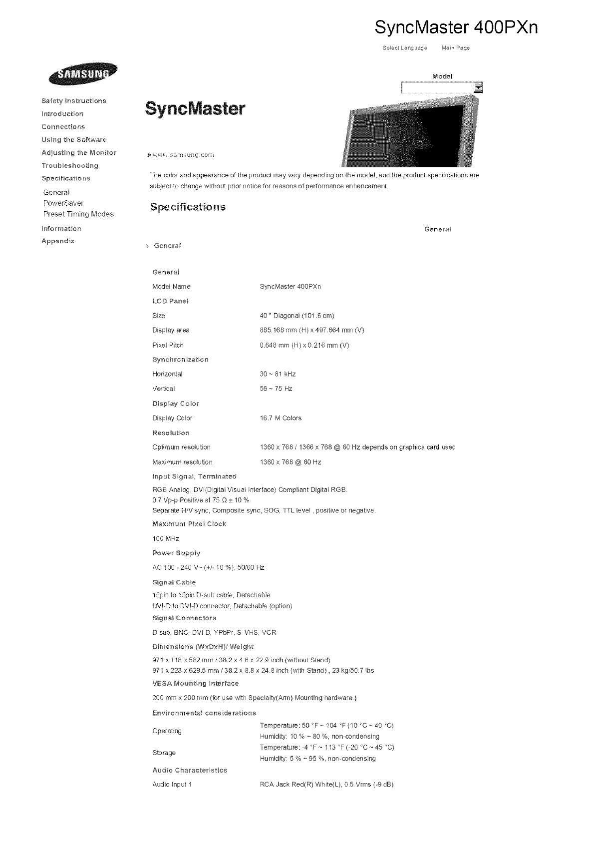
SyncMaster 400PXn
Select L_nguage Main Page
Safety Instructions
Iotroduet on
Connections
Usng the Software
Adjusting the Mo#itor
Troubleshooting
Specifications
General
PowerSaver
Preset Timing Modes
#_fermation
Appendix
SyncMaster
Mode_
The cobr and appearance of the product may vary depending on the model, and the product specifications are
subject to change without prior notice for reasons of performance enhancement.
Specifications
G@nell a
Gene_a
Genera
Model Name
LCD Panel
Size
Display area
Pixel Pitch
Synchrenizat on
Horizontal
Vertical
Diep ay Color
Display Color
Reso ut on
Optmura resolution
Maximum resolution
SyncMaster 400PXn
40" Diagonal (101.6 cm)
885168 mm (H)x 497664 mm (V)
0648 mm (N) x 0216 mm (V)
30 ~ 81 kHz
56 ~ 75 Hz
16.7 M Colors
1360 x 768 /1366 x 768 @ 60 Hz depends on graphics card used
1360 x 768 @ 60 Hz
Operating
Storage
Audio Charaeterist es
Audio input 1
Temperature: 50 °F ~ 104 °F (10 °C ~ 40 °C)
Humidity: 10 % ~ 80 %, non-condensing
Temperature: =4 °F ~ 113 °F (-20 °C ~ 45 °C)
Humidity: 5 % ~ 95 %, non-condensing
RCA Jack Red(R) White(L), 05 Vrms (-9 dB)
Input Signa, Term hated
RGB Analog, DVl(Digital Visual Interface) Compliant Digital RGB
0.7 Vp=p Positive at 75 Q ± 10 %
Separate H/V sync, Composite sync, SOG, TTL level, positive or negative
_#_aximum PxeH Cloak
100 MHz
Power Suppy
AC 100 -240 V~ (+/- 10 %), 50/60 Hz
Signa_ Cabe
15pin to 15pin D-sub cable, Detachable
DVI-D to DVI-D connector, Detachable (option)
Signa_ Coonectors
D-sub, BNC, DVI-D, YPbPr, S-VHS, VCR
Dimensions (WxDxH}/Weight
971 x 118 x 582 mm /382 x 4.6 x 22.9 inch (without Stand)
971 x 223 x 6295 mm /38.2 x 8.8 x 248 inch (with Stand), 23 kg/50 7 Ibs
VESA Mount ng Interface
200 mmx 200 mm (for use with Specialty(Arm) Mounting hardware)
Env ronmental considerat one
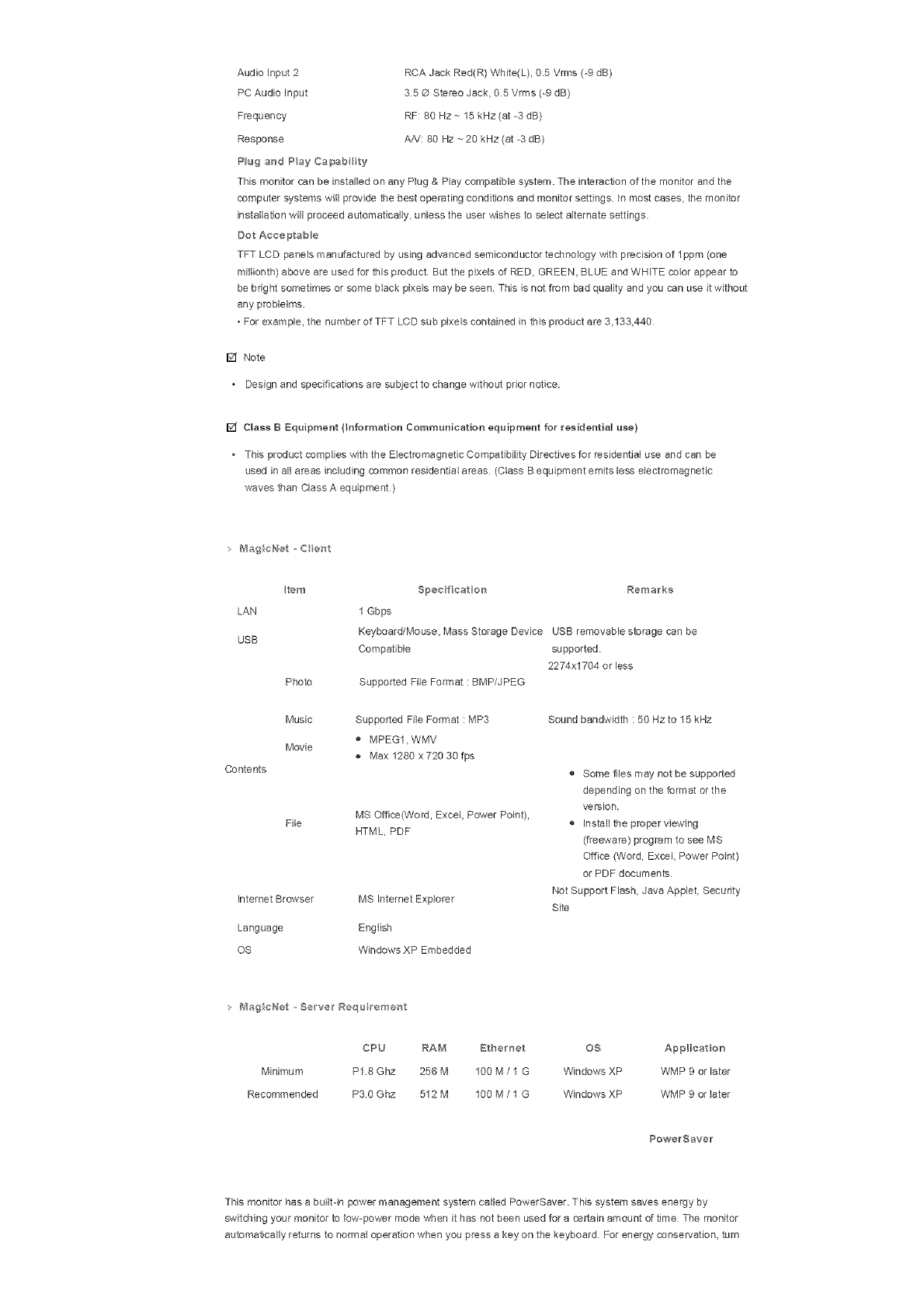
Audioinput2
PCAudioInput
Frequency
Response
PlugandPayCa_ab_ty
RCAJackRed(R)White(L),0.5Vrms(-9dB)
35@StereoJack,05Vrms(-9dB)
RF:80Hz~15kHz(at-3dB)
AA!:80Hz~20kHz(at-3dB)
ThismonitorcanbeinstalledonanyPlug&Playcompatiblesystem.Theinteracf,onofthemonitorandthe
computersystemswillprovidethebestoperatingconditionsandmonitorsettings.Inmostcases,themonitor
installationwillproceedautomatically,unlesstheuserwishestoselectalternatesettings.
DotAcceptable
TFTLCDpanelsmanufacturedbyusingadvancedsemiconductortechnologywithprecisionoflppm(one
miBonth)aboveareusedforthisproductButthepixelsofRED,GREEN,BLUEandWHITEcolorappearto
bebrightsometimesorsomeblackpixelsmaybeseen.Thisisnotfrombadqualityandyoucanuseitwithout
anyproblelms
•Forexample,thenumberofTFTLCDsubpixelscontainedinthisproductare3.133,440
[] Note
Designandspecificationsaresubjecttochangewithoutpriornotice.
[] ClassBEquipment(}nformationCommunicationequipmentforresidentialuse)
+ThisproductcomplieswiththeEbctromagnettsCompatibilityDirectivesforresidentialuseandcanbe
usedinallareasincludingcommonresidentialareas(ClassBequipmentemitslesselectromagnetic
wavesthanClassAequipment)
: B_agicNet,Cent
Item
LAN
USB
Photo
Music
Movie
Contents
File
InternetBrowser
Language
OS
Specfieaten Remarks
1Gbps
Keyboard/Mouse,MassStorageDeviceUSBremovablestoragecanbe
Compatible supported
2274x1704orless
SupportedFileFormat:BMP/JPEG
Supported File Format : MP3
MPEG1, WMV
Max 1280 x 720 30 fps
MS Offica(Word, Excel, Power Point),
HTML, PDF
MS Internet Expbrer
English
Windows XP Embedded
Sound bandwidth : 50 Hz to 15 kHz
® Some flies may not be supported
depending on the format or the
version.
® Install the proper viewing
(freeware) program to see MS
Office (Word, Excel, Power Point)
or PDF documents
Not Support Flash, Java Applet, Security
Site
MagieNet ,Se,rw;l Regu re'caent
CPU RAM Bthernet OS AppHeat on
Minimum P18 Ghz 256 M 100 M /1 G Windows XP WMP 9 or later
Recommended P30 Ghz 512 M 100 M /1 G Windows XP WMP 9 or later
PowerSave_
This monitor has a builtqn power management system called PowerSaver. This system saves energy by
switching your monitor to low-power mode when it has not been used for a certain amount of time The monitor
automatically returns to normal operation when you press a key on the keyboard For energy conservation, turn

yourmonitorOFFwhenitisnotneeded,orwhenleavingitunattendedforlongperiodsThePowerSaversystem
operateswithaVESADPMScompliantvideocardinstalledinyourcomputer.Usethesoftwareutilityinstalledon
yourcomputertosetupthisfeature.
Normal Powersaving Poweroff
State Poweroff
Operation mode BPA/ENBRGY2000
PowerIndicator Green Green,Blinking Amber Black
Lessthan Lessthan1W Lessthan1W 9W
PowerConsumption
230W (Off-mode) (Powerbutton) (PowerSwitch)
ThismonitorisEPAENERGYSTAR<R)compliantandENERGY2000
compliantwhenusedwithacomputerequippedwithVESADPMS
functionality
AsanENERGYSTARa)Partner,SAMSUNGhasdeterminedthatthis
productmeetstheENERGYSTAR_)guidelinesforenergyefficiency.
PresetTruingModes
;Preset "ll"miag _,,_odes
If the signal transferred from the computer is the same as the following Preset Timing Modes, the screen will be
adjusted automatically However, if the signal differs, the screen may go blank while the power LED is on Refer
to the video card manual and Adjusts the screen as follows.
DspMy Mode
IBM, 640 x 350
IBM, 640 x 480
IBM, 720 x 400
MAC 640 x 480
MAC 832 x 624
VESA 640 x 480
VESA 640 x 480
VESA 648 x 480
VESA 800 x 600
VESA 800 x 600
VESA 800 x 600
VESA 800 x600
VESA 800 x600
VESA 1024 x 768
VESA 1024 x 768
VESA 1024 x 768
VESA 1024 x 768
VESA 1360 x 768
/qorizonta _ Vertioa_ Pixel Cloak Syne Polarity
Frequency Freque_cy (MHa t (R/V}
(kHz} (Hz}
31.489 70.086 25.175 +1-
31.469 59.940 25.175 -/-
31.469 70.087 28322 -/+
35.000 86.667 30240 4-
49.726 74.551 57.284 4-
37.861 72.809 31 500 -/-
37.500 75000 31 500 -/-
43.269 85.008 36000 -/-
35 156 56 250 36000 +/+
37879 60.317 40000 +/+
48 077 72.188 50000 +/+
46875 75000 49500 +/+
53.674 85 080 56250 +/+
48.383 60.004 65 000 -/-
56 476 70.069 75 000 -/-
60.023 75.029 78750 +/+
68.677 85997 94500 +/+
47 712 80 000 85 500 +/+
Horizonta I Preque_cy
The time to scan one line connecting the right edge to the left edge of the
screen horizontally is called the Horizontal Cycle and the inverse number
of the Horizontal Cycle is called the Horizontal Frequency. Unit: kHz
Vertioa_ Frequency
Like a fluorescent lamp, the screen has to repeat the same image many
times per second to display an image to the user The frequency of this
repetition is called the Vertical Frequency or Refresh Rate. Unit: Hz
@ 1995--2007 SAMSUNG ALL Right Reserved

SyncMaster 400PX
Select L_nguage Main Page
Safety Instructions
Iotroduet or_
Conneetior_s
Usng the Software
Adjusting the Mo#itor
Troubleshooting
Specifications
General
PowerSaver
Preset Timing Modes
Information
Appendix
SyncMaster
Mode_
The cobr and appearance of the product may vary depending on the model, and the product specifications are
subject to change without prior notice for reasons of performance enhancement.
Specifications
Gertell a
Genera
Genera
Model Name
LCD Panel
Size
Display area
Pixel Pitch
Synchrenizat on
Horizontal
Vertical
Diep ay Color
Display Color
Reso ut on
Optmura resolution
Maximum resolution
SyncMaster 40OPX
40" Diagonal (101.6 cm)
885168 mm (H)x 497664 mm (V)
0648 mm (N) x 0216 mm (V)
30 ~ 81 kHz
56 ~ 75 Hz
16.7 M Colors
1360 x 768 /1366 x 768 @ 60 Hz depends on graphics card used
1360 x 768 @ 60 Hz
Operating
Storage
Audio Charaeterist ee
Audio input 1
Temperature: 50 °F ~ 104 °F (10 °C ~ 40 °C)
Humidity: 10 % ~ 80 %, non-condensing
Temperature: -4 °F ~ 113 °F (-20 °C ~ 45 °C)
Humidity: 5 % ~ 95 %, non-condensing
RCA Jack Red(R) White(L), 05 Vrms (-9 dB)
trtput Signa, Term hated
RGB Analog, DVl(Digital Visual Interface) Compliant Digital RGB
0.7 Vp-p Positive at 75 Q ± 10 %
Separate H/V sync, Composite sync, SOG, TTL level, positive or negative
_#_aximum Pixel Clock
100 MHz
Power Supply
AC 100 - 240 V_-(+/- 10 %), 50/60 Hz
Sig_a_ Cabe
15pin to 15pin D-sub cable, Detachable
DVI-D to DVI-D connector, Detachable (option)
Signa_ Coonectors
D-sub, BNC, DVI-D, YPbPr, S-VHS, VCR
Dir'aensione (WxDxH}/Weight
971 x 118 x 582 mm /382 x 4.6 x 22.9 inch (without Stand)
971 x 223 x 6295 mm /38.2 x 8.8 x 248 inch (with Stand), 23 kg/50 7 Ibs
VESA Mour_t r_g tr_tarfaee
200 mmx 200 mm (for use with Specialty(Arm) Mounting hardware)
Env ronmental considerat one
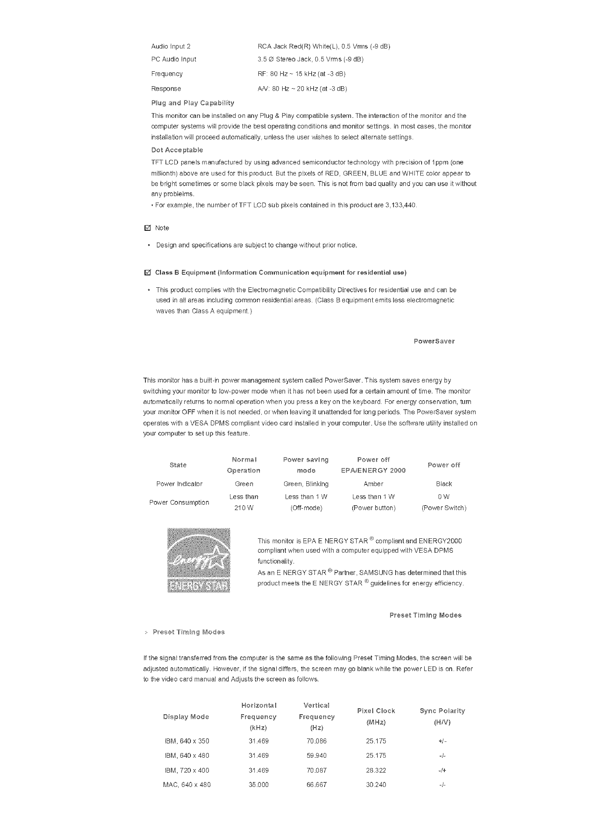
Audioinput2
PCAudioInput
Frequency
Response
PlugandPayCa_abty
RCAJackRed(R)White(L),0.5Vrms(-9dB)
35OStereoJack,05Vrms(-9dB)
RF:80Hz~15kHz(at-3dB)
AA!:80Hz~20kHz(at-3dB)
ThismonitorcanbeinstalledonanyPlug&Playcompatiblesystem.Theinteractionofthemonitorandthe
computersystemswillprovidethebestoperatingconditionsandmonitorsettings,inmostcases,themonitor
installationwillproceedautomatically+unlesstheuserwishestoselectalternatesettings.
DotAcceptable
TFTLCDpanelsmanufacturedbyusingadvancedsemiconductortechnologywithprecis+onoflppm(one
miBonth)aboveareusedforthisproductButthepixelsofRED+GREEN,BLUEandWHITEcolorappearto
bebrightsometimesorsomeblackpixeismaybeseen.Thislsnotfrombadqualityandyoucanuseitwithout
anyproblelms
+Forexample,thenumberofTFTLCDsubpixelscontainedinthisproductare3.133,440
[] Note
+ Designandspecificationsaresubjecttochangewithoutpriornotice.
[] Class B Equipment (}nformation Communication equipment for residential use)
+ This product complies with the Electromagnetic Compatibility Directives for residential use and can be
used in all areas including common residential areas (Class B equipment em+ts less electromagnetic
waves than Class A equipment)
PowerSaver
This monitor has a built-in power management system called PowerSaver. This system saves energy by
switcMng your monitor to low-power mode when it has not been used for a certain amount of time. The monitor
automat!cally returns to normal operation when you press a key on the keyboard For energy conservation, turn
your monitor OFF when it is not needed, or when leaving it unattended for long periods The PowerSaver system
operates with a VESA DPMS compliant video card installed in your computer. Use the software utility installed on
your computer to set up this feature.
Norma+ Power savng Power off
State Power off
Operation mode EPA/ENBRGY 2000
Power Indicator Green Green, Blinking Amber Black
Less than Less than I W Less than 1W OW
Power Consumption 210 W (Off-mode) (Power button) (Power Switch)
e)
This monitor is EPA ENERGY STAR compliant and ENERGY2000
compliant when used with a computer equipped with VESA DPMS
functionality
As an ENERGY STAR ® Partner, SAMSUNG has determined that tMs
product meets the ENERGY STAR ® guidelines for energy efficiency.
> Preset Truing diodes
Preset Truing Modes
If the signal transferred from the computer is the same as the following Preset Timing Modes, the screen wB be
adjusted automatically However, if the signal differs, the screen may go blank while the power LED is on Refer
to the video card manual and Adjusts the screen as follows.
Horizonta _ VerBca Pixel Clock Sync Po+ar ty
D sp_ay Mode Frequency Freque_cy /MHz) (B/V}
(kBz) (Hz)
iBM, 840 x 350 31.469 70.086 25.175 +/-
IBM, 640 x 480 31.469 59.940 25175 4-
iBM, 720 x 400 31.469 70.087 28.322 -/+
MAC, 840 x 480 35.000 68.667 30240 -/-

MAC832x624
VESA640x480
VESA640x480
VESA640x480
VESA800x600
VESA800x600
VESA800x600
VESA800x600
VESA800x600
VESA1024x768
VESA1024x768
VESA1024x768
VESA1024x768
VESA1360x768
49.726 74.551 57.284 -/-
37.861 72809 31 500 -/-
37 500 75.000 31 500 -/-
43 269 85 008 36000 -/-
35.156 56 250 36000 +/+
37.879 60317 40000 +/+
48.077 72.188 50000 +/+
46.875 75.000 49500 +/+
53 674 85.000 56250 +/+
48 363 60004 65000 -/-
56.476 70069 75000 -/-
60 023 75029 78750 +/+
68 677 85.997 94 500 +/+
47712 60.000 85500 +/+
Horizonta BFrequency
The time 1o scan one line connecting the right edge to the left edge of the
screen horizontally is called the Horizontal Cycle and the inverse number
of the Horizontal Cycle is called the Horizontal Frequency Unit: kHz
Vertical Frequency
Like a fluorescent lamp, the screen has to repeat the same image many
times per second to display an image to the user The frequency oftMs
repetition is called the Vertical Frequency or Refresh Rate Unit: Hz
@ 1995~2007 SAMSUNG. ALL Right Reserved

SyncMaster 460PXn
Select L_nguage Main Page
Safety Instructions
Iotroduet or_
Conneetior_s
Usng the Software
Adjusting the Mo#itor
Troubleshooting
Specifications
General
PowerSaver
Preset Timing Modes
Information
Appendix
SyncMaster
Mode_
The cobr and appearance of the product may vary depending on the model, and the product specifications are
subject to change without prior notice for reasons of performance enhancement.
Specifications
Genell a
Genera
Genera
Model Name
LCD Panel
Size
Display area
Pixel Pitch
Synchrenizat on
Horizontal
Vertical
Diep ay Color
Display Color
Reso ut on
Optmura resolution
Maximum resolution
SyncMaster 460PXn
46" Diagonal (125.1 cm)
1018.353 mm (H) x 572.544 mm (V)
07455 mm (H) x 02485 mm (W)
30 ~ 81 kHz
56 ~ 75 Hz
16.7 M Colors
1360 x 768 /1366 x 768 @ 60 Hz depends on graphics card used
1360 x 768 @ 60 Hz
Operating
Storage
Audio Charaeterist ee
Audio input 1
Temperature: 50 °F ~ 104 °F (10 °C ~ 40 °C)
Humidity: 10 % ~ 80 %, non-condensing
Temperature: -4 °F ~ 113 °F (-20 °C ~ 45 °C)
Humidity: 5 % ~ 95 %, non-condensing
RCA Jack Red(R) White(L), 05 Vrms (-9 dB)
trtput Signa, Term hated
RGB Analog, DVl(Digital Visual Interface) Compliant Digital RGB
0.7 Vp-p Positive at 75 Q ± 10 %
Separate H/V sync, Composite sync, SOG, TTL level, positive or negative
_#laximum PxeH Cloak
100 MHz
Power Suppy
AC 100 -240 V~ (+/- 10 %), 50/60 Hz
Sigr_a_ Cabe
15pin to 15pin D-sub cable, Detachable
DVI-D to DVI-D connector, Detachable (option)
SignaN Coonectors
D-sub, Bh;C, DVI-D, YPbPr, S-VHS, VCR
Dimensions (WxDxH}/Weight
1.102 x 658 x 1265mm /434 x 259 x 50 inch /28 Kg /61.6 Ibs (without Stand)
1.102 x 715 x 293 mm /434 x 281 x 115 inch /30 Kg /66 Ibs (with Stand)
VESA Mount r_g tr_terfaee
200 mmx 200 mm (for use with Specialty(Arm) Mounting hardware)
Env ror_mental eensiderat one

Audioinput2
PCAudioInput
Frequency
Response
PlugandPayCa_abty
RCAJackRed(R)White(L),0.5Vrms(-9dB)
35@StereoJack,05Vrms(-9dB)
RF:80Hz~15kHz(at-3dB)
AA!:80Hz~20kHz(at-3dB)
ThismonitorcanbeinstalledonanyPlug&Playcompatiblesystem.Theinteractionofthemonitorandthe
computersystemswillprovidethebestoperatingconditionsandmonitorsettings,inmostcases,themonitor
installationwillproceedautomatically,unlesstheuserwishestoselectalternatesettings.
DotAcceptable
TFTLCDpanelsmanufacturedbyusingadvancedsemiconductortechnologywithprecisionoflppm(one
miBonth)aboveareusedforthisproductButthepixelsofRED,GREEN,BLUEandWHITEcolorappearto
bebrightsometimesorsomeblackpixelsmaybeseen.Thisisnotfrombadqualityandyoucanuseitwithout
anyproblelms
•Forexample,thenumberofTFTLCDsubpixelscontainedinthisproductare3.133,440
[] Note
Designandspecificationsaresubjecttochangewithoutpriornotice.
[] ClassBEquipment(}nformationCommunicationequipmentforresidentialuse)
+ThisproductcomplieswiththeEbctromagnettsCompatibilityDirectivesforresidentialuseandcanbe
usedinallareasincludingcommonresidentialareas(ClassBequipmentemitslesselectromagnetic
wavesthanClassAequipment)
: B_agicNet,Cent
Item
LAN
USB
Photo
Music
Movie
Contents
File
InternetBrowser
Language
OS
Specfieaten Remarks
1Gbps
Keyboard/Mouse,MassStorageDeviceUSBremovablestoragecanbe
Compatible supported
2274x1704orless
SupportedFileFormat:BMP/JPEG
Supported File Format : MP3
MPEG1, WMV
Max 1280 x 720 30 fps
MS Offica(Word, Excel, Power Point),
HTML, PDF
MS Internet Expbrer
English
Windows XP Embedded
Sound bandwidth : 50 Hz to 15 kHz
® Some flies may not be supported
depending on the format or the
version.
® Install the proper viewing
(freeware) program to see MS
Office (Word, Excel, Power Point)
or PDF documents
Not Support Flash, Java Applet, Security
Site
MagieNet ,Se,rw;l Regu re'caent
CPU RAM Bthemet OS AppHeat on
Minimum P18 Ghz 256 M 100 M /1 G Windows XP WMP 9 or later
Recommended P30 Ghz 512 M 100 M /1 G Windows XP WMP 9 or later
PowerSave_
This monitor has a builtqn power management system called PowerSaver. This system saves energy by
switching your monitor to low-power mode when it has not been used for a certain amount of time The monitor
automatically returns to normal operation when you press a key on the keyboard For energy conservation, turn
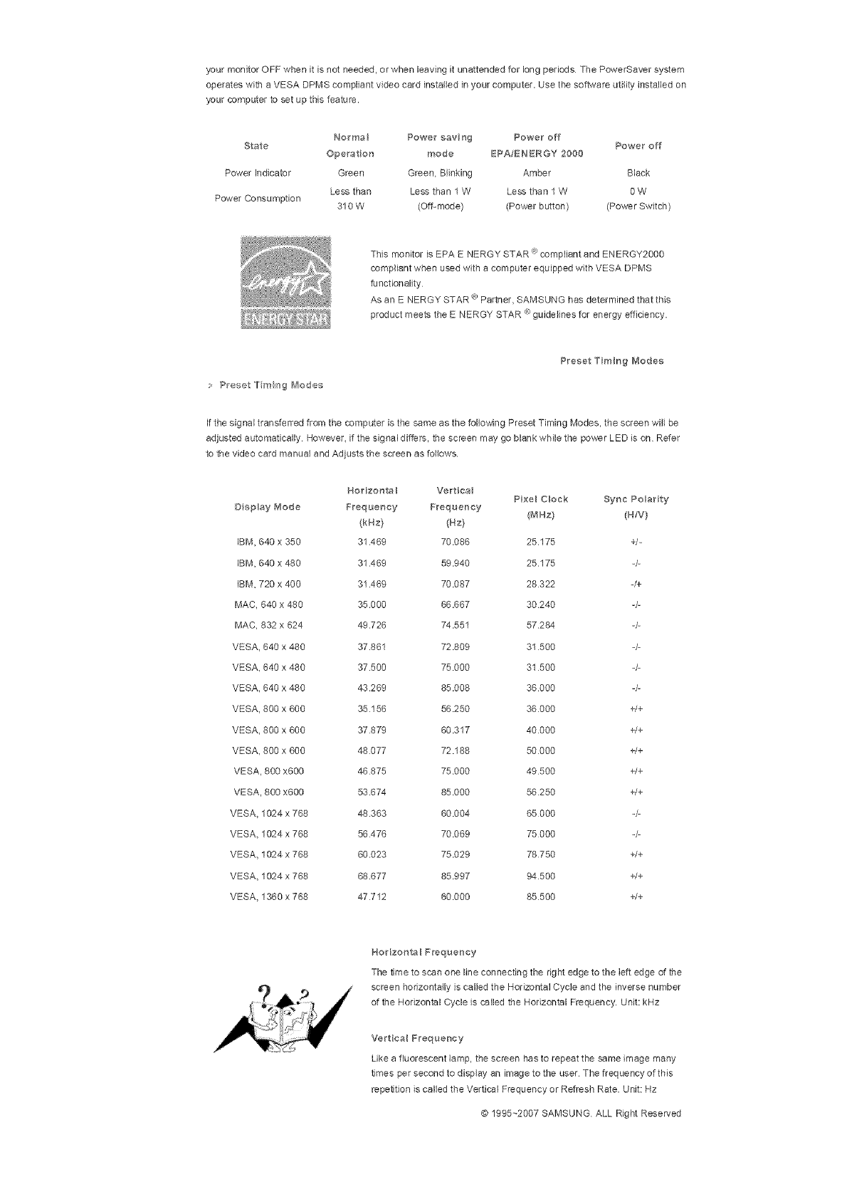
yourmonitorOFFwhenitisnotneeded,orwhenleavingitunattendedforlongperiodsThePowerSaversystem
operateswithaVESADPMScompliantvideocardinstalledinyourcomputer.Usethesoftwareutilityinstalledon
yourcomputertosetupthisfeature.
Normal Powersaving Poweroff
State Poweroff
Operation mode BPA/ENBRGY2000
PowerIndicator Green Green,Blinking Amber Black
Lessthan Lessthan1W Lessthan1W 9W
PowerConsumption
310W (Off-mode) (Powerbutton) (PowerSwitch)
ThismonitorisEPAENERGYSTAR<R)compliantandENERGY2000
compliantwhenusedwithacomputerequippedwithVESADPMS
functionality
AsanENERGYSTARa)Partner,SAMSUNGhasdeterminedthatthis
productmeetstheENERGYSTAR_)guidelinesforenergyefficiency.
PresetTruingModes
;Preset "ll"miag _,,_odes
If the signal transferred from the computer is the same as the following Preset Timing Modes, the screen will be
adjusted automatically However, if the signal differs, the screen may go blank while the power LED is on Refer
to the video card manual and Adjusts the screen as follows.
DspMy Mode
IBM, 640 x 350
IBM, 640 x 480
IBM, 720 x 400
MAC 640 x 480
MAC 832 x 624
VESA 640 x 480
VESA 640 x 480
VESA 648 x 480
VESA 800 x 600
VESA 800 x 600
VESA 800 x 600
VESA 800 x600
VESA 800 x600
VESA 1024 x 768
VESA 1024 x 768
VESA 1024 x 768
VESA 1024 x 768
VESA 1360 x 768
/qorizonta _ Vertioa_ Pixel Cloak Syne Polarity
Frequency Freque_cy (MHa t (R/V}
(kHz} (Hz}
31.489 70.086 25.175 +1-
31.469 59.940 25.175 -/-
31.469 70.087 28322 -/+
35.000 86.667 30240 4-
49.726 74.551 57.284 4-
37.861 72.809 31 500 -/-
37.500 75000 31 500 -/-
43.269 85.008 36000 -/-
35 156 56 250 36000 +/+
37879 60.317 40000 +/+
48 077 72.188 50000 +/+
46875 75000 49500 +/+
53.674 85 080 56250 +/+
48.383 60.004 65 000 -/-
56 476 70.069 75 000 -/-
60.023 75.029 78750 +/+
68.677 85997 94500 +/+
47 712 80 000 85 500 +/+
Horizonta I Preque_cy
The time to scan one line connecting the right edge to the left edge of the
screen horizontally is called the Horizontal Cycle and the inverse number
of the Horizontal Cycle is called the Horizontal Frequency. Unit: kHz
Vertioa_ Frequency
Like a fluorescent lamp, the screen has to repeat the same image many
times per second to display an image to the user The frequency of this
repetition is called the Vertical Frequency or Refresh Rate. Unit: Hz
@ 1995--2007 SAMSUNG ALL Right Reserved
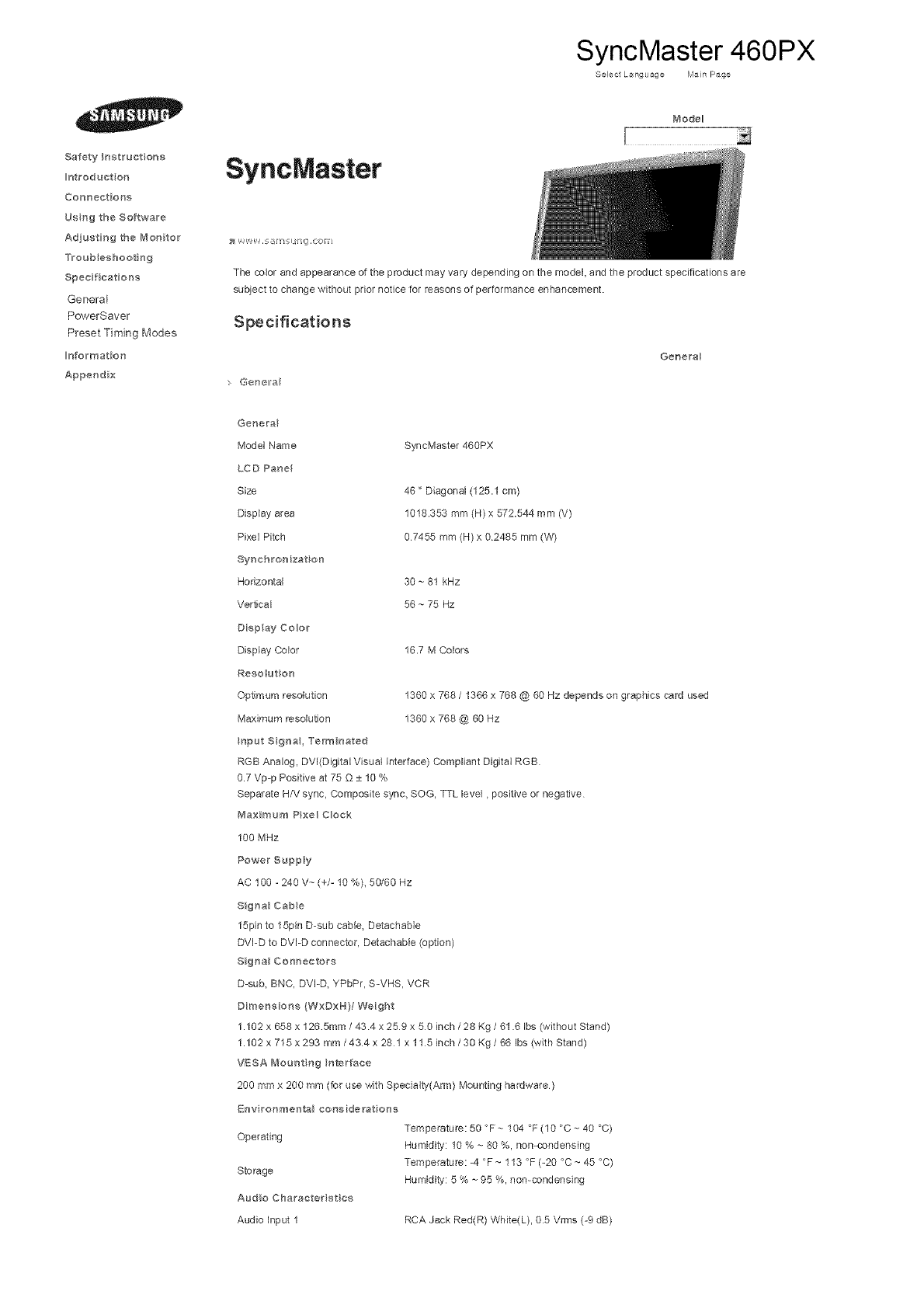
SyncMaster 460PX
Select L_nguage Main Page
Safety Instructions
Introduet on
Connections
Usng the Software
Adjusting the Monitor
Troubleshooting
Specifications
General
PowerSaver
Preset Timing Modes
Information
Appendix
SyncMaster
Mode_
The cobr and appearance of the product may vary depending on the model, and the product specifications are
subject to change without prior notice for reasons of performance enhancement.
Specifications
G@r_ell a
Gene_a
Genera
Mode] Name
LCD Panel
Size
Display area
Pixe] Pitch
Synchrenizat on
Horizontal
Vertical
Diep ay Color
Display Color
Reso ut on
Optmura reso[uSon
Maximum resolution
SyncMaster 46gPX
46" Diagonal (125.1 cm)
1018.353 mm (H) x 572.544 mm (V)
07455 mm (H) x 02485 mm (W)
30 ~ 81 kHz
56 ~ 75 Hz
16.7 M Colors
1360 x 768 /1366 x 768 @ 60 Hz depends on graphics card used
1360 x 768 @ 60 Hz
Operating
Storage
Audio Charaeterist es
Audio input 1
Temperature: 50 °F ~ 104 °F (10 °C ~ 40 °C)
Humidity: 10 % ~ 80 %, non-condensing
Temperature: -4 °F ~ 113 °F (-20 °C ~ 45 °C)
Humidity: 5 % ~ 95 %, non-condensing
RCA Jack Red(R) White(L), 05 Vrms (-9 dB)
trtput Signa, Term hated
RGB Analog, DV[(Digital Visual Interface) Compliant Digital RGB
0.7 Vp-p Positive at 75 Q ± 10 %
Separate H/V sync, Composite sync, SOG, TTL level, positive or negative
_'laximum Pixel Clock
100 MHz
Power Supply
AC 100 - 240 V_-(+/- 10 %), 50/60 Hz
Signa_ Cabe
15pin to 15pin D-sub cable, Detachable
DVI-D to DVI-D connector, Detachable (option)
SignaN Connectors
D-sub, BNC, DVI-D, YPbPr, S-VHS, VCR
Dimensions (WxDxH}/Weight
1.102 x 658 x 1265mm /434 x 259 x 50 inch /28 Kg /61.6 Ibs (without Stand)
1.102 x 715 x 293 mm /434 x 281 x 115 inch /30 Kg /66 Ibs (with Stand)
VESA Mount ng interface
200 mmx 200 mm (for use with Specialty(Arm) Mounting hardware)
Env ronmental ear,siderat one

Audioinput2
PCAudioInput
Frequency
Response
PlugandPayCa_ab_ty
RCAJackRed(R)White(L),0.5Vrms(-9dB)
35@StereoJack,05Vrms(-9dB)
RF:80Hz~15kHz(at-3dB)
AA!:80Hz~20kHz(at-3dB)
ThismonitorcanbeinstalledonanyPlug&Playcompatiblesystem.Theinteracf,onofthemonitorandthe
computersystemswillprovidethebestoperatingconditionsandmonitorsettings.Inmostcases,themonitor
installationwillproceedautomatically,unlesstheuserwishestoselectalternatesettings.
DotAcceptable
TFTLCDpanelsmanufacturedbyusingadvancedsemiconductortechnologywithprecisionoflppm(one
miBonth)aboveareusedforthisproductButthepixelsofRED,GREEN,BLUEandWHITEcolorappearto
bebrightsometimesorsomeblackpixelsmaybeseen.Thisisnotfrombadqualityandyoucanuseitwithout
anyproblelms
•Forexample,thenumberofTFTLCDsubpixelscontainedinthisproductare3.133,440
[] Note
Designandspecificationsaresubjecttochangewithoutpriornotice.
[] Class B Equipment (}nformation Communication equipment for residential use)
This product complies with the Ebctromagnetic Compatibility Directives for residential use and can be
used in all areas including common residential areas (Class B equipment emits less electromagnetic
waves than Class A equipment)
PowerSaver
This monitor has a builtqn power management system called PowerSaver. This system saves energy by
switcMng your monitor to low-power mode when it has not been used for a cer[ath amount of time. The monitor
automatically returns to normal operation when you press a key on the keyboard For energy conservation, turn
your monitor OFF when it is not needed, or when leaving it unattended for long periods The PowerSaver system
operates with a VESA DPMS compliant video card installed in your computer. Use the software utilit,y installed on
your computer to set up this feature.
Normal Power savng Power off
State Power off
Operation mode EPA/ENBRGY 2000
Power Indicator Green Green, Blinking Amber Black
Less than Less than I W Less than 1W OW
Power Consumption 290 W (Off-mode) (Power button) (Power Switch)
a)
This monitor is EPA ENERGY STAR compliant and ENERGY2000
compliant when used with a computer equipped with VESA DPMS
functionality
As an ENERGY STAR a) Partner, SAMSUNG has determined that this
product meets the E NERGY STAR _ guidelines for energy efficiency.
> Preset Truing diodes
Preset Truing Modes
If the signal transferred from the computer is the same as the following Preset Timing Modes, the screen wB be
adjusted automatically However, if the signal differs, the screen may go blank while the power LED is on Refer
to the video card manual and Adjusts the screen as follows.
Horizonta _ VerBca Pixel Clock Sync Polar ty
D sp_ay Mode Frequency Freque_cy (MHz) (B/V}
(kBz) (Hz)
iBM, 840 x 350 31.469 70.086 25.175 +/-
IBM, 640 x 480 31.469 59.940 25175 4-
iBM, 720 x 400 31.469 70.087 28.322 -/+
MAC, 840 x 480 35.000 68.667 30240 -/-
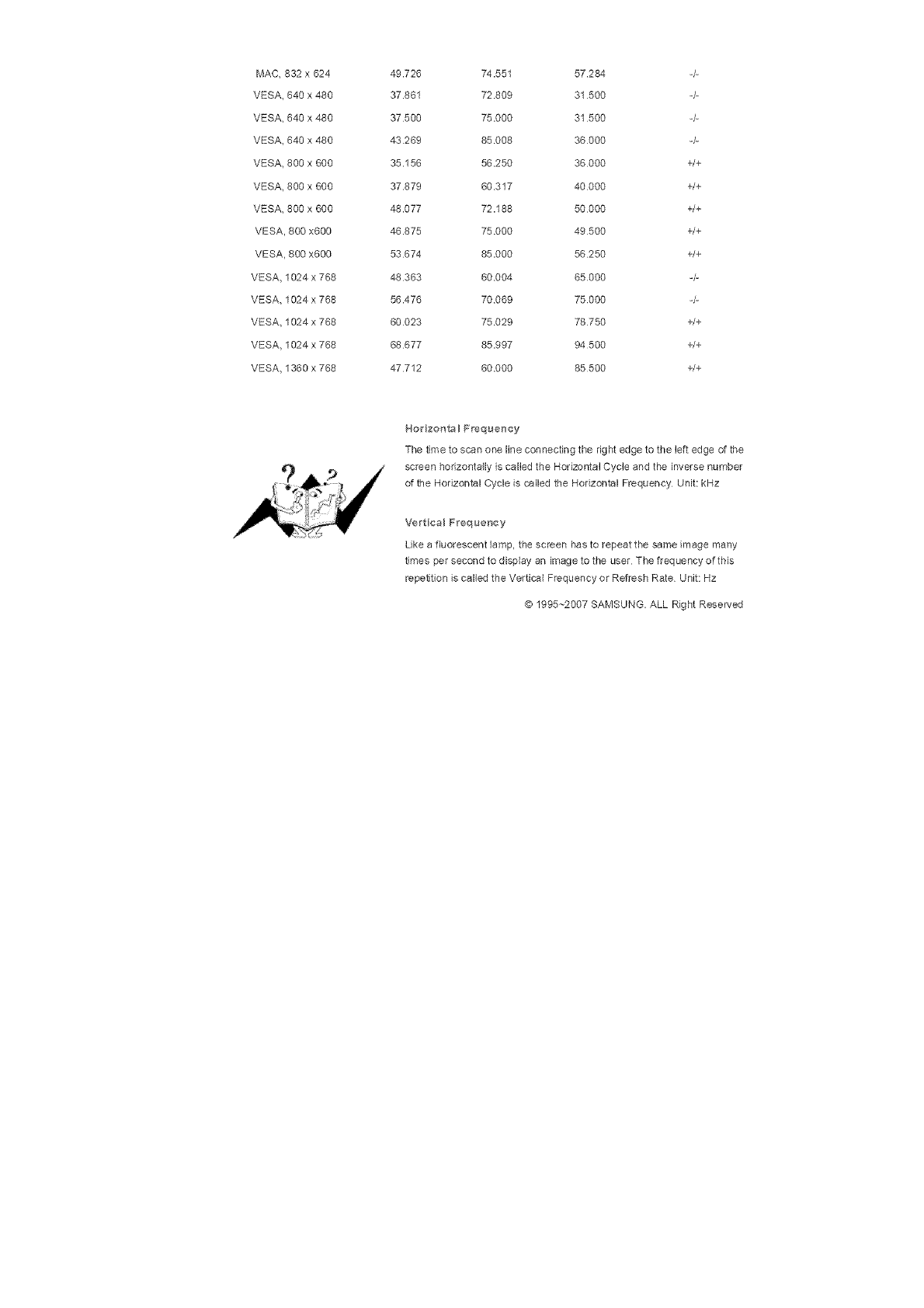
MAC832x624
VESA640x480
VESA640x480
VESA640x480
VESA800x600
VESA800x600
VESA800x600
VESA800x600
VESA800x600
VESA1024x768
VESA1024x768
VESA1024x768
VESA1024x768
VESA1360x768
49.726 74.551 57.284 -/-
37.861 72809 31 500 -/-
37 500 75.000 31 500 -/-
43 269 85 008 36000 -/-
35.156 56 250 36000 +/+
37.879 60317 40000 +/+
48.077 72.188 50000 +/+
46.875 75.000 49500 +/+
53 674 85.000 56250 +/+
48 363 60004 65000 -/-
56.476 70069 75000 -/-
60 023 75029 78750 +/+
68 677 85.997 94 500 +/+
47712 60.000 85500 +/+
Horizonta BFrequency
The time 1o scan one line connecting the right edge to the left edge of the
screen horizontally is called the Horizontal Cycle and the inverse number
of the Horizontal Cycle is called the Horizontal Frequency Unit: kHz
Vertical Frequency
Like a fluorescent lamp, the screen has to repeat the same image many
times per second to display an image to the user The frequency oftMs
repetition is called the Vertical Frequency or Refresh Rate Unit: Hz
@ 1995~2007 SAMSUNG. ALL Right Reserved
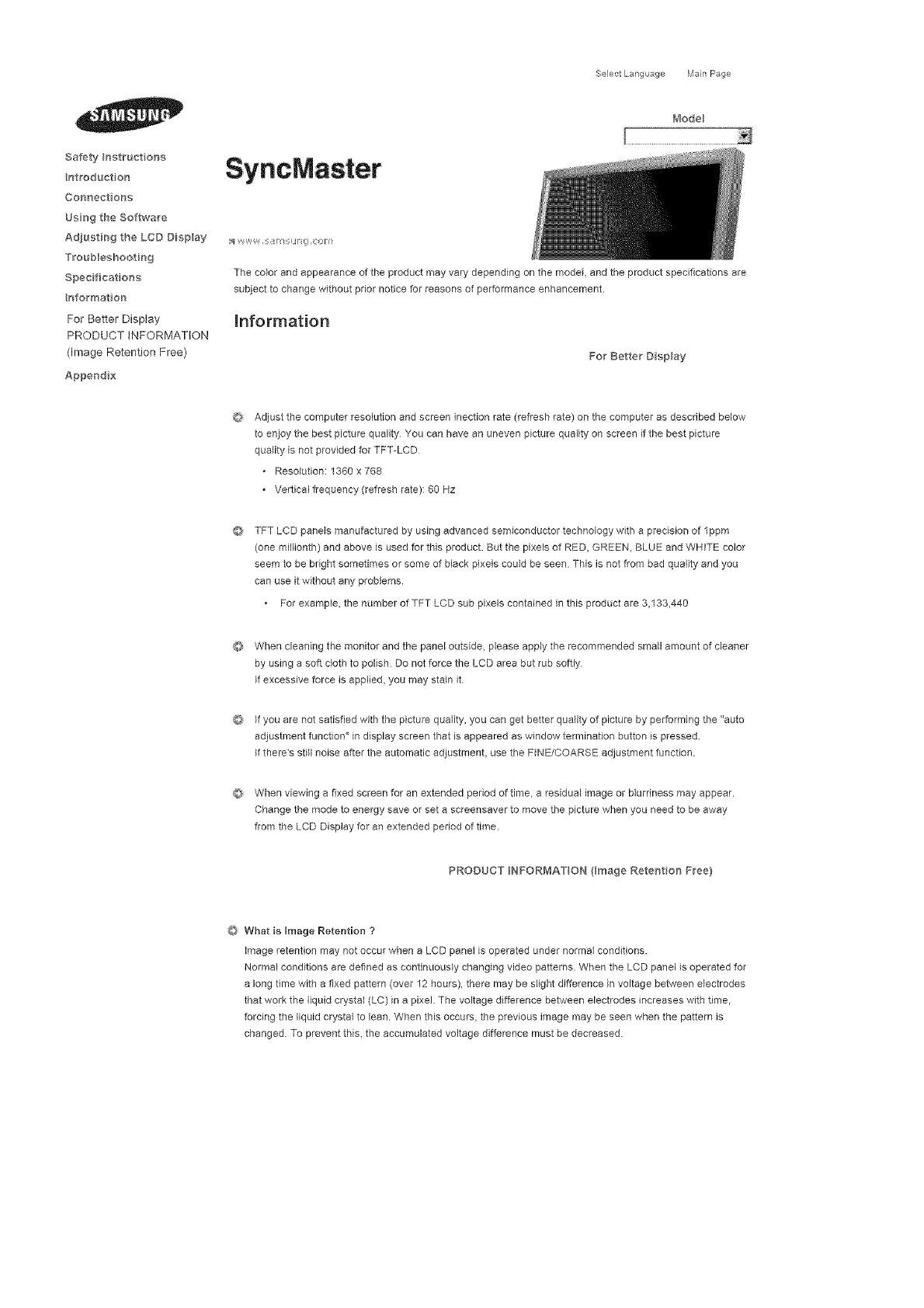
SafetyIr_atruetena
nt_oduetor_
Connectore{;
UsngtheSoftwar'e
Ad]ustir_g the LCD Display
Troub_eshootir_g
Spec ficat o_s
rfformat o_
For Better Display
PRODUCT INFORMATION
(Image Retention Free)
Apper_d x
Select Lang _age Man Page
SyncMaster
/_'_odeB
;_ v-,',,= W, ,#/_q F_il ,eonl
The color and appearance of the product may vary depending on the model and the product specifications are
subject to change without prior notice for reasons of performance enhancement.
information
For Better Display
©
Adjust the computer resolution and screen inecfion rate (refresh rate) on the computer as described below
to enjoy the best picture quality You can have an uneven picture quality on screen if the best picture
quality is not provided for TFT-LCD
* Resolution: 1360 x 768
Vertical frequency (refresh rate): 60 Hz
TFT LCD panels manufactured by using advanced semiconductor technology with e precision of lppm
(one miNionth) and above is used for this product. But the pixels of RED, GREEN, BLUE and WHITE color
seem to be bright sometimes or some of black pixeb could be seen This is not from bad quality and you
can use it without any problems.
• For example, the number of TFT LCD sub pixels contained in this product are 3,133,440
When cleaning the monitor end the panel outside, please apply the recommended small amount of cleaner
by using a soft cloth to polish Do not force the LCD area but rub softly
_fexcessive force is applied, you may stain it
If you are not satisfied with the picture quality, you can get better quality of picture by performing the "auto
adjustment function" in display screen that is appeared as window termination button is pressed
If there's still noise after the automatic adjustment, use the FINE/COARSE adjustment function.
When viewing a fixed screen for an extended period of time, a residual image or blurriness may appear.
Change the mode to energy save or set a screensaver to move the picture when you need to be away
from the LCD Display for an extended period of time.
PRODUCT NFORMAT ON (Bmage ReteHtior_ Free}
O What is Image Retention ?
image retention may not occur when a LCD panel is operated under normal conditions
Normal conditions are defined as continuously changing video patterns. When the LCD panel is operated for
a long time with a fixed pattern (over 12 hours), there may be slight difference in voltage between electrodes
that work the liquid crystal (LC) in a pixel. The voltage difference between electrodes increases with time,
forcing the liquid crystal to lean When this occurs, the previous image may be seen when the pattern is
changed. To prevent this, the accumulated voltage difference must be decreased.
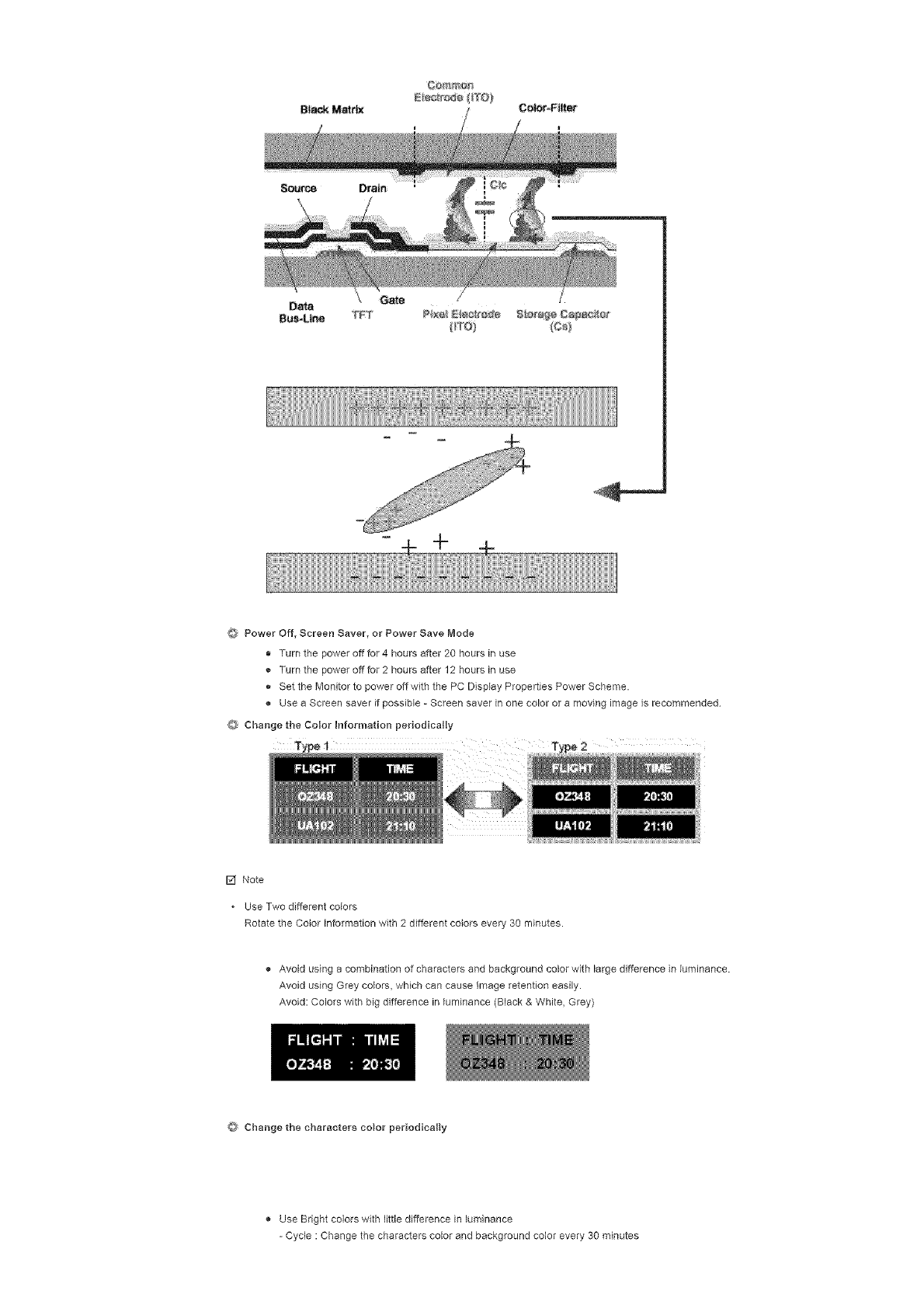
÷
OPower Off, Screen Saver, or Power Save Mode
• Turn the power off for 4 hours after 20 hours in use
o Turn the power off for 2 hours after 12 hours in use
o Set the Monitor to power off with the PC Display Properties Power Scheme.
Use a Screen saver if possible - Screen saver in one color or a moving image is recommended
O Change the Color Information periodically
[] Note
* Use Two different colors
Rotate the Color information with 2 different colors every 30 minutes.
Avoid using a combination of characters and background color with large difference in luminance.
Avoid using Grey colors, which can cause Image retention easily.
Avoid: Colors with big difference in luminance (Black & White, Grey)
Change the characters color periodically
Use Bright colors with little difference in luminance
- Cycle : Change the characters color and background color every 30 minutes
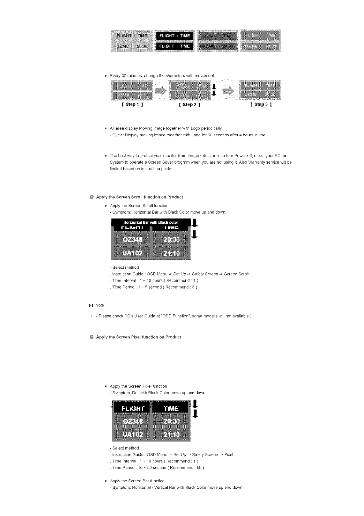
Every30minutes,changethecharacterswithmovement.
[ _epl ] [ Step2 ][ _ep3
All area display Moving image together with Logo periodically
= Cycle: Display moving image together with Logo for 60 seconds after 4 hours in use
The best way to protect your monitor from Image retention is to turn Power off, or set your PC, or
System to operate a Screen Saver program when you are not using it Also Warranty service will be
limited based on instruction guide.
O Apply the Screen Scroll function on Product
Apply the Screen Scroll function
= Symptom: Horizontal Bar with Black Color move up and down
= Select method
instruction Guide : OSD Menu => Set Up -> Safety Screen => Screen Scroll
Time interval : 1 ~ 10 hours ( Recommend : 1 )
Time Period : 1 ~ 5 second ( Recommend : 5 )
F,2fNote
* ( Please check CD's User Guide at "OSD Function", some model's will not available )
Apply the Screen Pixel function on Product
,_ Apply the Screen Pixal function
- Symptom: Dot with Black Color move up and down
1
!
- Select method
Instruction Guide : OSD Menu -> Set Up -> Safety Screen -> Pixe_
Time Interval : 1 ~ 10 hours ( Recommend : 1 )
Time Period : 10 -- 50 second ( Recommend : 50 )
Apply the Screen Bar function
= Symptom: Horizontal /Vertical Bar with Black Color move up and down.
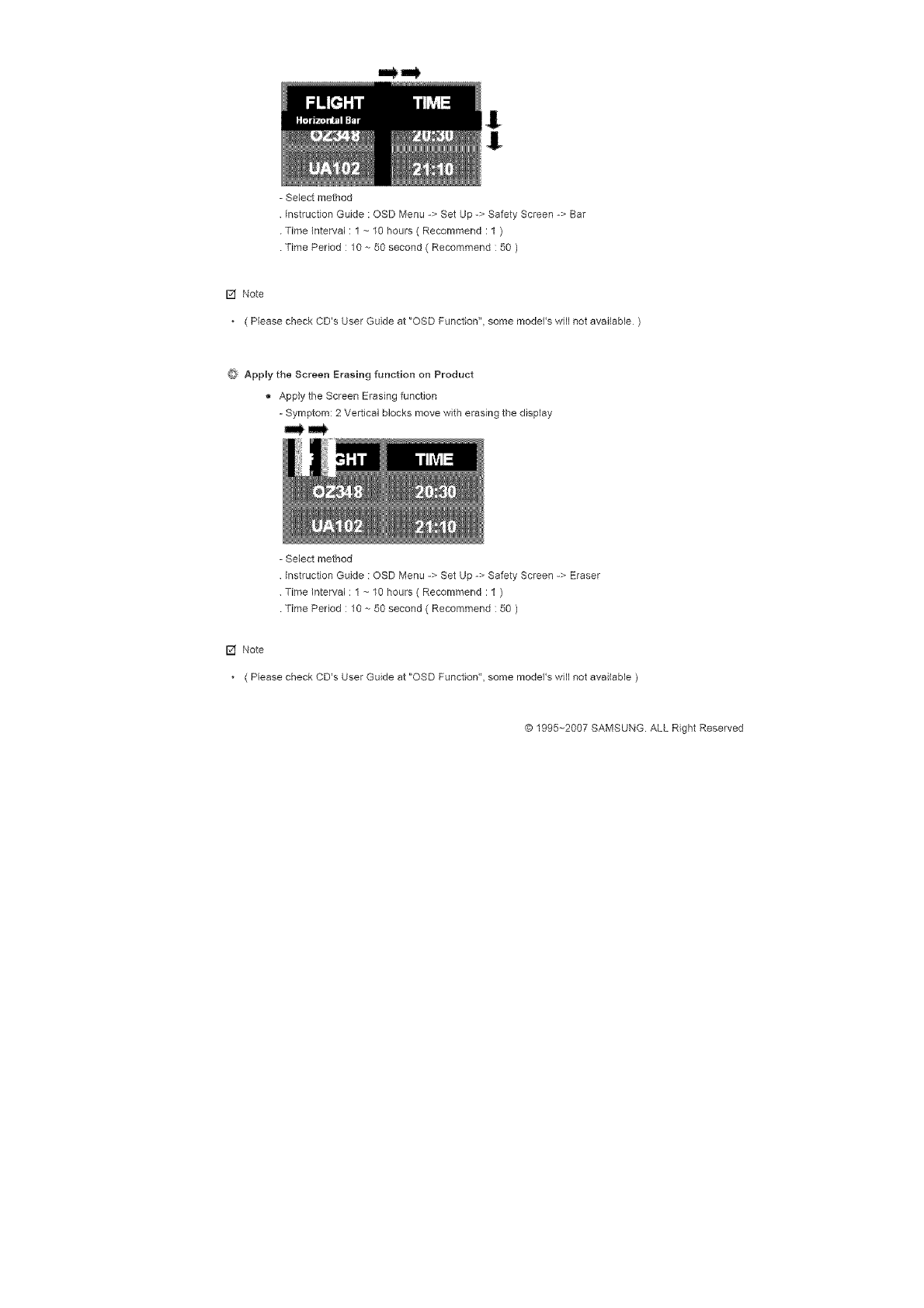
-Selectmethod
InstructionGuide:OSDMenu->SetUp->SafetyScreen->Bar
TimeInterval:1~10hours(Recommend:1)
TimePeriod:10--50second(Recommend:50)
F,2fNote
* ( Please check CD's User Guide at "OSD Function", some model's will not available )
Apply the Screen Erasing function on Product
Apply the Screen Erasing function
- Symptom: 2 Vertical blocks move with erasing the display
- Select method
instruction Guide : OSD Menu -> Set Up -> Safety Screen -> Eraser
Time interval : 1 ~ 10 hours ( Recommend : 1 )
Time Period : 10 -- 50 second ( Recommend : 50 )
[] Note
( Please check CD's User Guide at "OSD Function", some model's will not ave#able )
© 1995~2007 SAMSUNG. ALL Right Reserved
Safety Instruct ens
hotroduet on
Connections
Usn 9 the Software
Ad}ustin 9 the LCD Disp ay
Troub:eshootin 9
Specifications
Hnfermatien
Appendix
Contact SAMSUNG
WORLDWIDE
Terms
Correct Disposal
Authority
SyncMaster
Select Language Main Page
Model
The color and appearance of the product may vary depending on the model, and the product specifications are
subject to change without prior notice for reasons of performance enhancement.
Appendix
Contact SAMSUNG WORLDWIDE
[] Note
.If you have any questions or comments relating to Samsung products, please contact the SAMSUNG
customer care center.
U.S,A 1-8OO-SAMSUNG (7267864) http://_vww.sa msun g com
CANADA 1-8OO-SAMSUNG (7267864) http://_vww.sa msun g com/ca
MEXICO 01-80O-SAMSUNG (7267864) http:/_vww.sa msun g com/mx
ARGENTINE 0800-333-3733
BRAZIL 4004-0000
CH ILE 800-726-7864 (SAMSUNG)
COLOMBIA 01-8000112112
COSTA R_CA 0-600-507-7267
ECUADOR 1-800-10-7267
EL SALVADOR 800-6225
GUATEMALA 1-800-299-0013
JAMAICA 1-800-234=7267
PANAMA 800-7267
PU ERTO RICO 1-800-682-3180
REP, DOMIMCA 1-800-751-2676
TRINIDAD & TOBAGO 1-600-7267-864
VE NEZU ELA 1-600-100-5303
http://_vww.sa msun g com/a r
http://_vww.sa msun g com/b r
http:/_vww.sa msun g com/cl
http:/_vww.sa msun g com.co
http:/_vww.sa msun g com/latin
http:/_vww.sa msun g com/latin
http:/_vww.sa msun g com/latin
http:/_vww.sa msun g com/latin
http:/_vww.sa msun g com/latin
http:/_vww.sa msun g com/latin
http:/_vww.sa msun g com/latin
http:/_vww.sa msun g com/latin
http:/_vww.sa msun g com/latin
http:/_vww.sa msun g com/latin
BELGIUM
CZECH REPUBLIC
02 201 2418
844 000 844
http://_vww.sa msun g com/be
http:/_ww.sa msun g com/cz
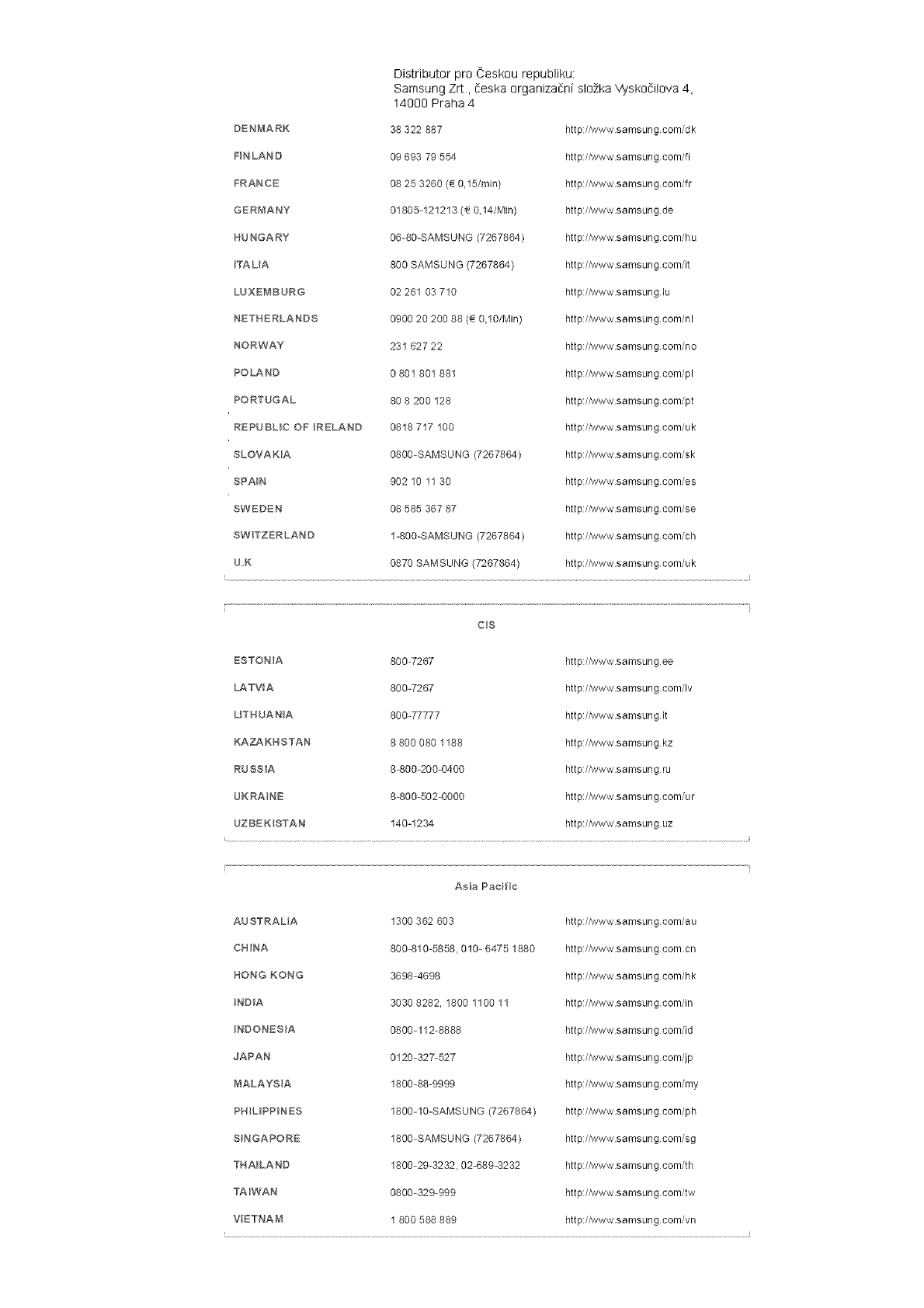
Distributor pro Ceskou republiku:
Samsung Zrt, deska organizadni slo2ka Wskodilova 4,
14000 Praha 4
DENMARK 38 322 887 http:/Adww.samsung com/dk
FIN LAND 09 693 79 554 http://Www.samsung com/fi
FRANCE 08 25 3260 (_ 0,15/min) http:/_ww.samsung com/fr
GERMANY 01805-121213 (A 0,14/Min) http:/_vww.samsung de
HUNGARY 06-80-SAMSUNG (7267864) http:/_ww.sa msun g com/h u
BTALIA 800 SAMSUNG (7267864) http:/Adww.samsung com/it
LUXEMBURG 02 261 03 710 http://Www.samsung lu
NETHERLANDS 0900 20 200 88 (_ 0,10/Min) http:/iwww.samsungcom/nl
NORWAY 281 627 22 http:/_vww.samsung com/no
POLAND 0 801 801 881 http:/_ww.samsung com/pl
PORTUGAL 80 8 200 128 http:/_vww.samsung com/pt
REPUBLIC OF RELAND 0818 717 100 http:/_ww.samsung com/uk
SLOVAKBA 0800-SAMSUNG (7267864) http:/_vww.sa msun g com/sk
SPA_N 902 10 11 30 http:/iwww.samsungcom/es
SWEDEN 08 585 367 87 http:/_ww.samsung com/se
SWITZERLAND 1-800-SAMSUNG (7267864) http:/_vww.sa msun g com/ch
U.K 0870 SAMSUNG (7267864) http:/Adww.samsung com/uk
C_S
ESTONIA 800-7267 http:/Adww.samsung ee
LATVIA 800-7267 http:/Adww.sa msun g com/Iv
LITHUANIA 800-77777 http:/_ww.samsung It
KAZAKHSTAN 8 800 080 1188 http:/_vww.samsung kz
RUSSIA 8-800-200-0400 http:/_ww.samsung ru
UKRAINE 8-800-502-0000 http:/_vww.sa msun g com/u r
UZBEKISTAN 140-1234 http:/_!ww.samsung uz
Asia Pacfc
AUSTRALIA 1300 362 603 http://Www.samsung com/au
CN INA 800-810-5858, 010- 6475 1880 http:/_vww.sa msun g com.cn
HONG KONG 3698-4698 http://Www.sa msun g com/h k
INDIA 3030 8282, 1800 1100 11 http://Www.samsung com/in
INDONESIA 0800-112-8888 http:/_vww.sa msun g com/id
JAPAN 0120-327-527 http:/_ww.sa msun g com/jp
MALAYSIA 1800-88-9999 http:/Adww.sa msun g com/my
PHL_PPINES 1800-10-SAMSUNG (7267864) http:/_ww.sa msun g com/p h
S_NGAPORE 1800-SAMSUNG (7267864) http:/_vww.sa msun g com/sg
THAILAND 1800-29-3232, 02-689-3232 http://Www.sa msun g com/t h
TA_WAN 0800-329-999 http:/_ww.sa msun g com/tw
VIETNAM 1 800 588 889 http:/_vww.samsung com/vn
_idd e East & Af_iaa
SOUTH AFRICA 0860 7267864 (SAMSUNG) http:/hdww.samsung com/za
U,A,E 800SAMSUNG (7267864) http:/iwww.samsung com/mea
8000-4726
Terms
Syne Signal
Sync (Synchronized) Signals refer to the standard signals that are required to display desired colors on the
LCD Display. They are divided into Vertical and Horizontal Sync Signals. These signals display normal color
images by the set resolution and frequency.
Types of Sync Signals
Separate This is a scheme of transmitlng individual vertical sync signals to the LCD Display.
Composite This is a scheme of combining vertical sync signals into one composite signal end
transmitting it to the LCD Display. The LCD Display displays the color signals by
separating the composite signal into original color signals
Dot Pitch
The image on a LCD Display is composed of red, green and blue dots The closer the dots, the higher the
resolution The distance between two dots of the same color is called the 'Dot Pitch' Unit: mm
Vertical Frequency
The screen must be redrawn several times per second in order to create and display an image for the user.
The frequency of this repetition per second is called the Vertical Frequency or Refresh Rate Unit: Hz
IExample: IIf tile same light repeats itself 60 times per second, this is regarded as 60 Hz I
HoMzonta I Frequency
The time to scan one line connecting the right edge to the left edge of the screen horizontally is called the
Horizontal Cycle. The inverse number of the Horizontal Cycle is called Horizontal Frequency Unit: kHz
Interlace and Nono_nterlace Methods
Show;ng the horizontal lines of the screen from the top to the bottom sequentially is called the Non-Interlace
method while showing odd lines and then even lines in turn is called the Interlace method. The Non-thterlace
method is used for the majority of LCD Display s to ensure a dear image The interlace method is the same
as that used in TVs
Plug & Play
This is a Dnction that provides the best quality screen for the user by allowing the computer and the LCD
Display to exchange information automatically This LCD Display follows the international standard VESA
DDC for the Plug & P_ay function
Resolution
The number of horizontal and vertical dots used to compose the screen image is called the 'resolution'. This
number shows the accuracy of the display A high resolution is good for performing multiple tasks as more
image information can be shown on the screen.
iExample: Ill the resolution is 1360 x 768, this means the screen is composed of 1360 horizontal dots ii
_(horizontal resolution) and 768 vertical lines (vertical resolution) j
d_u_tiple Display Centre (MDC}
A Multiple Display Control (MDC) is an application allowing various displays to be easily and simultaneously
operated on a PC RS-232C. a standard of serial communication, is used for communicating between a PC
and a display.
Correct Disposal
@ Correct Dsposal of This Product (Waste Eleetrica_ & Electronic Equipment) ,-Europe only
(ApplicablentheEuropeanU_ionandotherEuropeancountrieswith
separatecollectionsystems)
Thismarkingshownontheproductoritsliterature,indicatesthatitshouldnotbe
disposedwithotherhouseholdwasteattheend®fitsworkinglifeToprevent
possibleharmtotheenvironmentordamagetohealthfromuncontrolledwaste
disposal,pleaseseparatethisfromothertypesofwasteandrecycleitresponsibly
topromotethesustainablereuseofmaterialresources
Householdusersshouldcontacteithertheretailerwheretheypurchasedthis
product,ortheirlocalgovernmentof_,ce,fordetailsofwhereandhowtheycan
takethisitemforenvironmentallysaferecycling
Businessusersshouldcontacttheirsupplierandcheckthetermsandconditions
ofthepurchasecontractThisproductshouldnotbemixedwithothercommercial
wastesfordisposal.
Authority
Informationinthis document is subject to change without notice.
@2007 Samsung Electronics Co., Ltd. All rights reserved.
Reproduction in any manner whatsoever without the written permission of Samsung Electronics Co, Ltd is
strictly forbidden.
Samsung Electronics Co., Ltd. shall not be liable for errors contained herein or for incidental or consequential
damages in connection with the furnisMng, performance, or use of this material
Samsung is the registered trademark of Samsung Electronics Co, Ltd.; Microsoft, Windows and Windows NT
are registered trademarks of Microsoft Corporation; VESA, DPMS and DDC are registered trademarks of Video
Electronics Standard Association; the ENERGY STAR ® name and logo are registered trademarks of the US
Environmental Protection Agency (EPA) As an ENERGY STAR ® Partner, Samsung Electronics Co., Ltd. has
determined that this product meets the ENERGY STAR ® guidelines for energy efficiency. All other product
names mentioned herein may be the trademarks or registered trademarks of their respective owners
IMPORTADO POR:
EXPORTADO POR:
MEXICO
SAMSUNG ELECTRONICS MEXICO SA de CV
Via Lopez Portillo No 6, Col San Fco. Chilpan
Tultitlan, Estado de Mexico, CP. 54940
Tel: 01-55-5747-510O /01-800-726-7864
Samsung Electronics CO,LTD.
416, Mae tan-3dong, Yeongtong -gu,
Suwon City, Gyeonggi-do Korea
@1995~2007 SAMSUNG ALL Rights Reserved
