Samsung Dvr Svr 1670 Users Manual
SVR-1670 to the manual 8b4ed900-b3a0-40a3-9ff9-a78badc974ee
2015-01-23
: Samsung Samsung-Samsung-Dvr-Svr-1670-Users-Manual-278308 samsung-samsung-dvr-svr-1670-users-manual-278308 samsung pdf
Open the PDF directly: View PDF ![]() .
.
Page Count: 65
Digital Video Recorder User Guide
1
Before installing and operang this product,
please read this manual thoroughly.
Digital Video Recorder SVR-1670 User Guide
ENGLISH
Firmware Version 1.0.0

Digital Video Recorder User Guide
2
Digital Video Recorder User Guide
3
Samsung does not assume any other responsibility concerning the sale of this product and does not
delegate any right to a third party to take any responsibility on its behalf. Product warranty does not
cover accident, negligence, alteration, misuse or abuse. In addition, no warranty is offered for any
attachments or parts not supplied by the manufacturer.
The warranty period for this product is three (3) years from the date of purchase. The warranty period
for HDD and Fan is one year after purchase.
The following are not covered by the warranty:
•Malfunctionduetonegligenceorimproperhandlingbyuser
•Deliberatedisassemblyandreplacementbyuser
•Connectiontoanimproperpowersupply
•Malfunctioncausedbynaturaldisasters(re,ood,etc.)
•Replacementofexpendableparts(HDD,Fan,etc.)
•Replacementofexpendablepartsusingonesfromanunauthorizedthirdparty
Warranty only refers to the warranty covering products that have been purchased. During the warranty
period,repairandexaminationofitemsoutsidethewarrantyscopewillbeprovidedforafee.After
thewarrantyperiodexpires,examinationandrepairoftheproductwillbeprovidedforafee.
Thisproductisnotintendedtobetheprimarymeansforpreventingreandtheft.Thecompanyisnot
responsible for any accidents or damage that may occur as a result of using this product.
Prior experience and technical expertise is required to install the product. Installing the product
withoutproper knowledgecan causere,electric shock,or otherdamage.Installation shouldbe
performed by the agency from which you purchased the product.
Samsungmay implement,without priornotice,rmwareorsoftwareupgrades or changestothe
appearance of the product.
Copyingandreprintingthismanual, eitherpartiallyorinitsentirety,or translating itinto another
languagewithout theconsent ofSamsungTechwin,Inc.is prohibited.Copyingfor generaluse is
acceptable if within copyright law.
Table of contents
Product Warranty and Limits of Responsibility
ProductWarrantyandLimitsofResponsibility ………………………………… 2
Table of contents ……………………………………………………………… 3
Chapter1.AboutSafety,ComplianceandDisposal ……………………………… 5
1. 1 Warnings ……………………………………………………………… 5
1. 2 Cautions ……………………………………………………………… 6
1. 3 Compliance Statements ………………………………………………… 6
1. 4 Disposal Procedures …………………………………………………… 7
Chapter2.SVR-1670Description ……………………………………………… 7
2. 1 About the SVR ………………………………………………………… 8
2. 2 Features ……………………………………………………………… 8
2. 3 Package Contents ……………………………………………………… 10
2. 4 Front Panel Overview …………………………………………………… 11
2. 5 Rear Panel Overview …………………………………………………… 13
2. 6 The Remote Control …………………………………………………… 14
Chapter3.HardwareInstallation …………………………………………… 17
3. 1 Installing the SVR-1670 in a Rack ……………………………………… 18
3. 2 Working with Input/Output Terminals …………………………………… 18
3. 3 Basic Connections to the SVR-1670 …………………………………… 19
3. 4 Extended Connections to the SVR-1670 ………………………………… 25
3. 5 Remote Monitoring and Control ………………………………………… 31
3. 6 Hard Disk Drive Installation……………………………………………… 32
Chapter4.Navigation:On-ScreenDisplayandFunctionMenus ……………… 38
4. 1 Working with the On-Screen Display …………………………………… 38
4. 2 Working with the Function Key Menu …………………………………… 42
Chapter5.QuickSetup ……………………………………………………… 44
5. 1. Working on the Quick Setup Menu ……………………………………… 44
5. 2. Setting the Record Mode ……………………………………………… 45
5. 3. Setting the Date and Time ……………………………………………… 46
Chapter6.UsingtheSystemSetupMenu …………………………………… 47
6. 1 Using the System Setup Options ………………………………………… 47
6. 2 Using the Disk Options on the System Setup Menu ……………………… 50
6. 3 Working with Passwords and Permissions ……………………………… 52
Chapter7.CommunicationTo/FromtheDVR ……………………………… 55
7. 1. Setting up Network Communication …………………………………… 55
7. 2. Registering with a DDNS Server ………………………………………… 58
7. 3. Setting up for NTP Synchronization …………………………………… 62
7. 4. Setting up Remote Control Devices …………………………………… 63
7. 5 Setting Up Streaming Options …………………………………………… 65
7. 6 Setting Up IP Filters …………………………………………………… 65
Digital Video Recorder User Guide
4
Digital Video Recorder User Guide
5
Table of contents
Chapter 1. About Safety, Compliance and Disposal
ThischapterexplainsimportantinformationaboutsafeuseoftheSVR-1670,itscompliancetoFCCandECORoHS
regulation,andhowtoproperlydisposeoftheequipment.
The information is presented in these sections:
•1.1Warnings
•1.2Cautions
•1.3ComplianceStatements
•1.4DisposalProcedures
SamsungTechwin,althoughnotresponsibleforaccidentsordamagethatmightoccurasaresultofusingthisSVR-
1670,wantsyoutouseitwiselyandsafely.Inthissection,weprovideseveralwarningsyoushouldfollowbefore
installingtheequipment,duringoperation,andifdismantlingorcleaningtheequipment.
• Before installation
Toavoidre,explosion,malfunctionorelectricshock,observethesepractices:
-Disconnectthepowersupplybeforeinstallation.
-Verifythatyoucaninstalltocorrectvoltage(AC100V~AC240V)beforeconnectingtopowersupply.
-Neverinstallinaveryhumidenvironment.
-ProperlygroundtheSVR-1670aswellasanyequipmentyouareconnectingtoit.
• During operation
Toavoidre,explosion,malfunctionorelectricshock,observethesepractices:
-IftheSVR-1670covereverneedstobeopened,relyonqualiedpersonnelorsysteminstallers,whoknow
how to do safely.
-Neverplugmultipleappliancesintoasinglepoweroutlet.
-Neverplaceheavyobjectsordishesholdingwateronproduct.
-NeverusetheSVR-1670whereexcessivedustorammablesubstancessuchaspropanegasarepresent.
-Nevertouchpowerlinewithwethand.
-NeverinserthandintotheDVDdock.
-Neverputconductivematerialsintothecoolingventilatoropening.
-Neverapplyexcessiveforcewhenpullingonpowercord.
-Replacebuilt-inbatterywithsamebatterytype.Disposeofoldbatteriesproperly
-Neverplacebatterynearreorextremeheat.
-Neverdissectordisassemblebattery.
• Dismantling and Cleaning
-Useadryclothtocleantheexterior.
-Neverusewater,paintthinnerororganicsolventtocleantheproductexterior.
-Neverdeliberatelydismantle,repairormodifyproduct.
Heed these warnings to prevent serious injury, shock or death.
1. 1 Warnings
Chapter8.WorkingwithEvents ……………………………………………… 66
8. 1 About Events …………………………………………………………… 66
8. 2 Setting Up for Event Recording ………………………………………… 66
8. 3 Working with Normal Events …………………………………………… 69
8. 4 Working with Presets …………………………………………………… 72
8. 5 Working with Digital I/O ………………………………………………… 72
8. 6 Defining Programs ……………………………………………………… 74
8. 7 Setting Up To Record …………………………………………………… 76
Chapter9.CameraandMonitorDisplaySetup ……………………………… 80
9. 1 Setting Up the Camera Display ………………………………………… 80
9. 2 About Multichannel Screen Display ……………………………………… 81
9. 3 Setting Up the Monitor Display ………………………………………… 82
9. 4 Using Auto Sequencing ………………………………………………… 83
9. 5 Configuring Multi Display Layouts ……………………………………… 84
Chapter10.CameraCommandss …………………………………………… 85
10. 1 Camera Commands from the FUNC Key Menu ………………………… 85
10. 2 Pan/Tilt/Zoom Commands …………………………………………… 85
Chapter11.WorkingwithRecordedVideo …………………………………… 88
11. 1 Various Playback Options ……………………………………………… 88
11. 2 Searching for Recorded Video ………………………………………… 89
11. 3 About Copying Video ………………………………………………… 92
Chapter12.UsingWebViewer ……………………………………………… 94
12. 1 System Requirements ………………………………………………… 94
12. 2 Starting Web Viewer …………………………………………………… 94
12. 3 Monitoring …………………………………………………………… 95
12. 4 Playback ……………………………………………………………… 98
AppendixA.SpecificationsoftheSVR-1670 ………………………………… 100
AppendixB.RecordingProgramDefaultSettings …………………………… 102
AppendixC.SupportedPTZControllersandProtocols ……………………… 104
AppendixD.FactoryDefaultSettings ………………………………………… 106
AppendixE.Glossary ………………………………………………………… 116
Dimension ………………………………………………………………… 121
Memo …………………………………………………………………… 122
Digital Video Recorder User Guide
6
Digital Video Recorder User Guide
7
Chapter 1. About Safety, Compliance and Disposal
• During Installation
Preventaccidentsandavoidinjuryormalfunction,observethesepractices:
- For adequate ventilation, install the SVR-1670 with at least 6 in (15cm) of space between cooler fan and wall surface.
- Install on a flat surface.
- Never install in areas exposed to direct sunlight or excessive heat.
- Connect a camera to the SVR-1670 before recording and storing images. (If a camera is installed while SVR-1670 is
recording, the image in another channel might be disrupted.)
• During Use
- Never expose the SVR-1670 to shocks or shaking during use.
- Never move, throw or expose to excessive physical shock during use.
- Installing unapproved hard disk drives can result in abnormal operation. Use only approved products. The SVR-1670’s
product warranty does not cover malfunction due to installation of unapproved hard disk drives.
- Samsung Techwin recommends the installation of a UPS (Uninterrupted Power Supply) with all its recording products.
ThefollowingproceduresareapplicableintheEuropeanUnionandotherEuropeancountriesto
complywithcorrectdisposalofwasteelectricalandelectronicequipment,andbatteries.
• Correct Disposal of Waste Electrical and Electronic Equipment
This marking, shown on the product or its literature, indicates that it should not be
disposed of with other household wastes at the end of its working life. To prevent
possible harm to the environment or human health from uncontrolled waste disposal,
please separate this from other types of wastes and recycle it responsibly. Household
users should contact either the retailer where they purchased this product, or their local
governmentofce,fordetailsofwhereandhowtheycantakethisitemforenvironmentally-safe
recycling.Businessusersshouldcontacttheirsupplierandcheckthetermsandconditionsofthe
purchasecontract.Thisproductshouldnotbemixedwithothercommercialwastesfordisposal.
• Correct Disposal of Batteries
This marking on the battery, manual or packaging indicates that the batteries in this
product should not be disposed of with other household waste at the end of their
working life. Where marked, the chemical symbols Hg, Cd or Pb indicate that the
batterycontainsmercury,cadmiumorleadabovethereferencelevelsinECDirective
2006/66.Ifbatteriesarenotproperlydisposedof,thesesubstancescancauseharmtohuman
health or the environment. To protect natural resources and to promote material reuse, please
separate batteries from other types of waste and recycle them through your local, free battery
returnsystem.Therechargeablebatteryincorporatedinthisproductisnotuser-replaceable.For
information on its replacement, please contact your service provider.
Chapter 2. SVR-1670 Description
Heed these cautions to prevent minor injury to users or damage to the equipment. You will
see other cautions throughout this manual. Cautions are indicated by the exclamation point
symbol.
Samsung Techwin, although not responsible for accidents or damage that might occur as a result of using this
product, wants you to use it wisely and safely. In this section, we provide several cautions you need to follow
beforeinstallingoroperatingtheequipment.
• FCC Compliance Statement
ThisequipmenthasbeentestedandfoundtocomplywiththelimitsforaClassAdigitaldevice,pursuanttopart
15oftheFCCRules.Theselimitsaredesignedtoprovidereasonableprotectionagainstharmfulinterference
whentheequipmentisoperatedinacommercialenvironment.Thisequipmentgenerates,uses,andcanradiate
radiofrequencyenergyand,ifnotinstalledandusedinaccordancewiththeinstructionmanual,mightcause
harmfulinterferencetoradiocommunications.Operationofthisequipmentinaresidentialareaislikelytocause
harmfulinterferenceinwhichcasetheuserwillberequiredtocorrecttheinterferenceathisexpense.
• ECO RoHS Compliance
Samsung Techwin cares for the environment and strives to preserve it during all
product manufacturing stages and to provide customers with environment-friendly
products. The Eco mark represents Samsung Techwin’s goal to create environment-
friendly products and indicates that the product satises the EU RoHS Directive.
1. 2 Cautions
1. 3 Compliance Statements
ThischapterprovidesinformationabouttheSamsungSVRseriesSVR-1670(digitalvideorecorder)andcontainsa
descriptionofSVRpartsandaccessories.
The information is presented in these sections:
•2.1AbouttheSVR-1670
•2.2Features
•2.3PackageContents
•2.4FrontPanelOverview
•2.5RearPanelOverview
•2.6TheRemoteControl
1. 4 Disposal Procedures

Digital Video Recorder User Guide
8
Digital Video Recorder User Guide
9
The SVR-1670 in the Samsung SVR series records and plays video from up to 16 channels. In
addition,theSVRcanalertyouoftheoccurrenceofuser-denedevents,suchasmotiondetection,
usingthebuzzer,onthescreen,orviae-mail.Variousmethodsareprovidedtocongureandcontrol
thisproduct:thefrontpanel controlboard,mouse,remotecontroller,WebViewer,SVM-S1(CMS:
CentralizedManagementSoftware),andcontroller.
Recordedhigh-qualityvideolesaresavedintheharddiskdriveforsearchandplaypurposes.You
canrecord,play,andcopyvideolesfrommultiplechannelsinrealtime.ThisSVRprovidesavariety
ofadvancedoptions:motiondetection,PTZcontrols(Pan/Tilt/Zoom),userpermissionsettingsand
accesscontrol,real-timeaudiorecording,eventloggingandsearch.
2. 1 About the SVR
2. 2 Features
Chapter 2. SVR-1670 Description
ThevariousfeaturesoftheSVR-1670arediscussedbelowandinclude:
•MonitoringScreen
•VideoRecording
•AudioRecording
•SearchandPlayback
•DataStorage
•Networking
•AdditionalFeatures
• Monitoring Screen
Themonitoringscreenprovidesvivid,high-denitionlivevideofeedsfromall16channels.Onthesplit-screen,
youcanview4,9,10,or16channelsaswellassingle-channeldisplay.Tofacilitateviewing,anauto-sequencing
feature automatically switches to each connected channel after a set interval.
- To the SVR-1670, two composite monitors and a single VGA monitor can be connected.
• Video Recording
TheSVR-1670storesvideoimagedataashigh-resolutionH.264lesatamaximumrateof480framesper
second.Whenrecordingvideobasedonevents,pre-eventvideoofuptovesecondsisalsorecorded.Withan
advanced“covert”feature,theSVR-1670protectsthepublic’sprivacybyidentifyingcertainareasintheeldof
view that are concealed during recording.
ToeffectivelymanagethedatastoragecapacityoftheSVR,youcanadjustitsrecordingperformanceusing
softwarethatdenestheresolution,framerate,andrecordingquality.
Motion detection settings, recording rates and recording modes can be programmed for each channel
individually.
TheSVR-1670providesseveralrecordingfunctionstoaccommodateanycombinationofmanualandscheduled
recording.Alongwithmultiplerecordingmodes,userscanperformallofthefollowingfunctionssimultaneously:
viewrecordedvideo,recordvideo,backupvideototheharddiskorexternalstoragemedia,andmonitorand
perform other networking operations.
Aneventlogstoresinformationonalleventsensoractivity,digitalinput/outputactivity,videolossdetection,and
text-basedtransactions.
• Audio Recording
TheSVR-1670supportsreal-timeaudioinputandrecordingfor16channelssimultaneously.FourRCAchannels
and12D-SUBChannels are provided on the rearpanel along withone audiooutput channelfor use witha
microphone.Audiocanberecordedandplayedbacksimultaneously.
• Search and Playback
SearchandplaybackoptionsontheSVR-1670includesupportforplaybackbasedontime,dateandchannel,a
graphical interface to input data search criteria, forward and backward search of paused video, playback logs
for all events, full frame playback, and access to search functions from the remote control or the front panel
JOG/SHUTTLE.
• Data Storage
Aharddiskisincludedwiththeproductfordatastorage.Therecordeddataalsocanbestoredtoexternalmedia
suchasaDVD+R,DVD-R,CD-RorUSB.
Whenusedinconjunctionwithexternalstorage,theSVS-5Rcansaveupto32TBofdata.
• Networking
The SVR-1670 supports LAN, RTSP protocol and xDSL networking capabilities across a 10/100/1000 Mpbs Ethernet
connection.SeveralSVR-1670scanbeconnectedacrossanetwork.CombinedwiththePCinterfaceclient,thecorefeatures
ofthedevicecaneasilybecontrolledremotely.Anetworkconnectionisrequiredforthefollowingfeatures:
-E-mailnoticationofevents,whichcanbesentviaTCP/IPorDHCP
-Remotemonitoringoflivevideo
-RunningtheSVM-S1tosearchforandplaybackrecordedvideo,managestoragedevices,setuprecordingschedules,and
controltheSVR-1670remotely
• Additional Features
ThefollowingfeaturesarealsoavailableontheSVR-1670:
-18-languageOSD:Korean,English,Japanese, Chinese,Taiwanese,Spanish,French,Italian,German,Portuguese, Polish,
Turkish,Russian,Swedish,Danish,Serbian,Rumanian,andCzech)
-EasyrmwareupgradeviaUSBoroverthenetwork.
-PTZcontrolandPresetfunction
Digital Video Recorder User Guide
10
Digital Video Recorder User Guide
11
Chapter 2. SVR-1670 Description
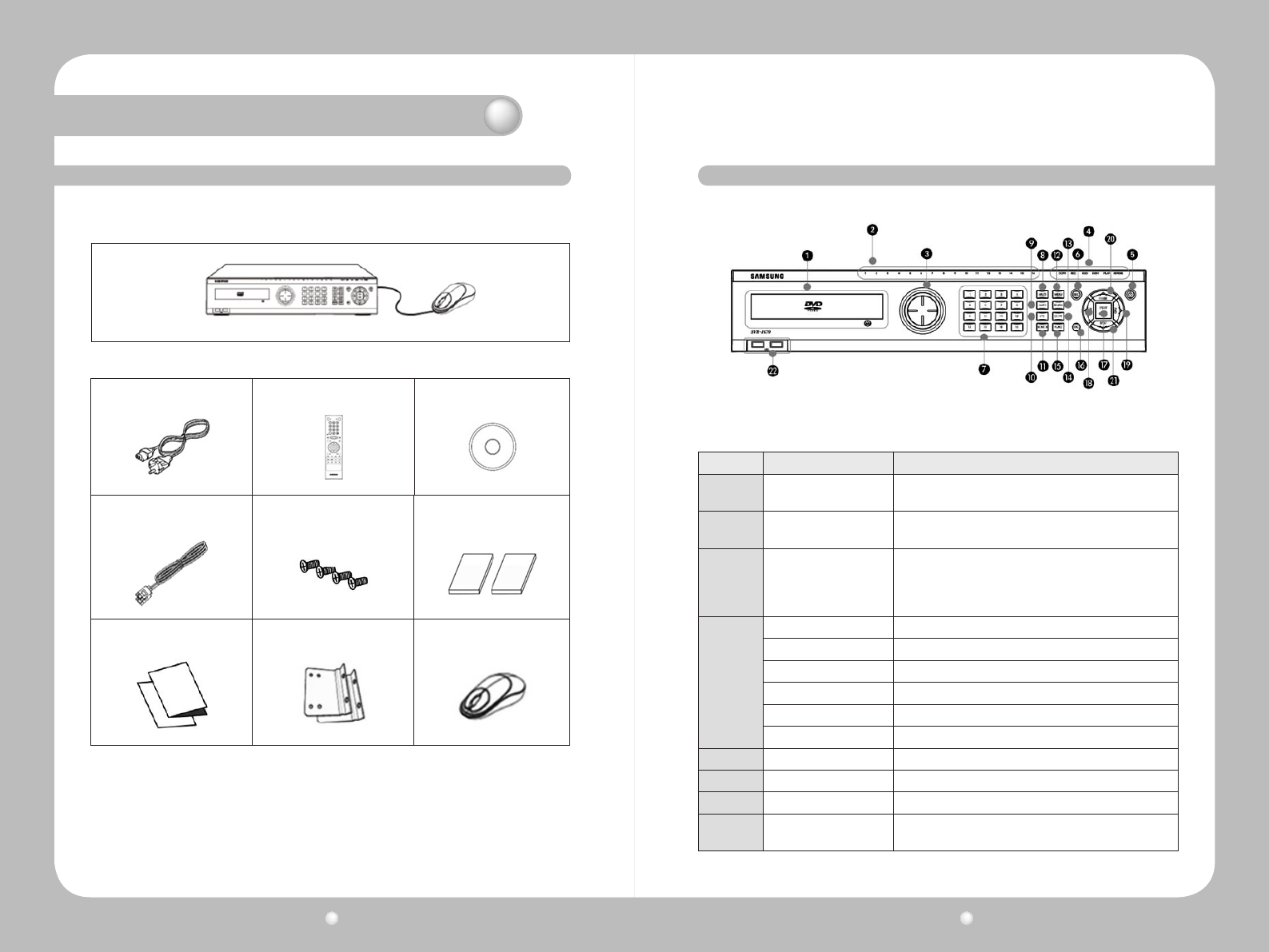
RefertothepackagecontentsdiagramtoensurethatallaccessoriesareprovidedwithyourSVR-
1670.
2. 3 Package Contents
Figure 2.3.1 Package Contents – SVR-1670 and Mouse
AC CORD Remote controller Program CD
SATA Cable HDD Mount Screw SVR-1670 Quick Guide / SVR-1670
User's Guide
Quick Guide Rack Mount Mouse
Figure 2.3.2 Package Contents Diagram
ThefrontpaneloftheSVR-1670hasthefollowingcontrolsandindicators:
Figure 2.4.1 SVR-1670 Front Panel
2. 4 Front Panel Overview
No. Name Function
1DVD-Multi drive Copies recorded video and images to DVD or CD-ROM
optical media.
2Channel LED Shows data input and event operation status for each
attached camera.
3JOG/SHUTTLE
Use the jog dial to search recorded video precisely per
frame.
The shuttle can be used to change the play speed while
playing or searching video, forward or backward.
4
REC light Lit when the unit is recording.
HDD light Lit when the hard disk is active.
NETWORK light Lit during network activity.
EVENT light Lit to indicate event detection.
COPY light Lit when copying.
PLAY light Lit during copying of live video.
5Power button Turns SVR-1670 on or off.
6REC button Starts or stops manual recording.
7Channel button Selects the channel to view live or playback video.
8MULTI Changes split-screen sections for live video feeds or
playback.
Digital Video Recorder User Guide
12
Digital Video Recorder User Guide
13
9AUTO Starts or stops user-defined sequences.
10 PTZ Starts or stops a PTZ function.
11 MONITOR Switches between the main and spot monitors.
12 MENU Opens the on-screen display menu.
13 SEARCH Starts Search mode.
14 COPY Starts Copy mode.
15 FUNC Starts Function mode.
16 ESC Each time pressed, closes open submenus and menus.
17 PLAY/ENTER Starts playback or selects an item on the menu.
18
◀
/REW Goes to or selects in the menu. For playback, changes the
reverse playback speed.
19
▶
/FFW Goes to or selects in the menu. For playback, changes the
forward playback speed.
20
▲
/PAUSE Goes to or selects in the menu. For playback, pauses live or
recorded video.
21
▼
/STOP Goes to or selects in the menu. For playback, stops playback.
22 USB1, USB2 USB ports for external devices (mouse, USB memory stick).
Chapter 2. SVR-1670 Description
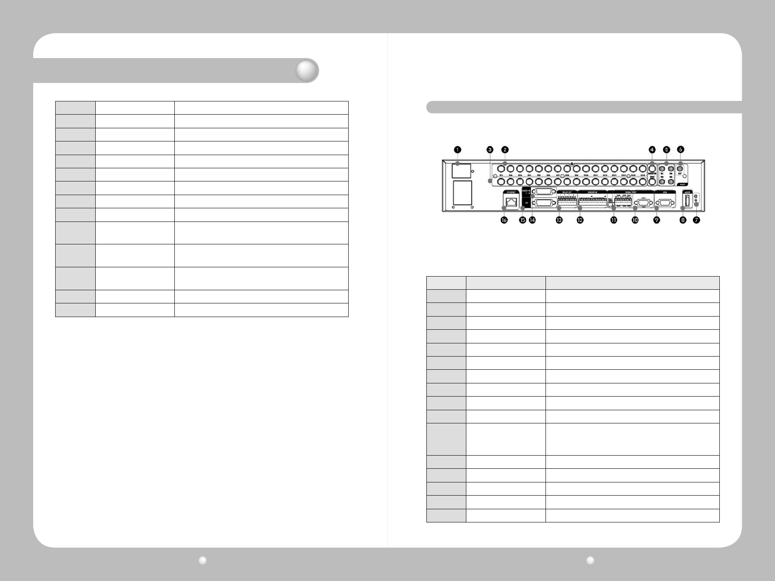
TherearpaneloftheSVR-1670hasthefollowingconnections:
Figure 2.5.1 SVR-1670 Rear Panel
2. 5 Rear Panel Overview
No. TerminalName Function
1Power Input Socket for AC 100V ~ AC 240V power cord
2Ch1 ~ 16 Connection terminal for camera BNC input
3Loop Out Connection terminal for camera BNC output (loop)
4Monitor 1~2 Connection terminal for monitor BNC output
5Audio In (RCA) RCA audio jack for RCA input
6Audio Out Audio jack for speaker output
7Ground A terminal that is used to ground SVR-1670 main frame.
8eSATA A terminal for an external eSATA backup device.
9VGA Output Output port for PC monitor
10 Serial Port RS-232C D-SUB connector
11
Serial Port
(Terminal Block)
(RS-232C/485/422)
Connection terminal for expanded control, speed dome
camera, and other such equipment.
12 Sensor In Connection terminal for sensor input
13 Relay Out Connection terminal for relay output
14 Audio In (D-SUB) Connection terminal for audio output D-SUB
15 D-I/O Connection terminal for Digital In/Out
16 Ethernet Ethernet port for network connections (RJ-45)
Digital Video Recorder User Guide
14
Digital Video Recorder User Guide
15
2. 6 The Remote Control
YoucancontrolallSVR-1670featuresusingtheremotecontroldevice.Youcanalsocontrolmultiple
SVR-1670sfromoneremotecontroldevice.Thissectionexplainshowinthesetopics:
•ButtonsontheRemoteControl.
•SettingUnitSVR-1670IDs.
•UsableRangeofRemoteControl.
•ChangingBatteries.
Chapter 2. SVR-1670 Description
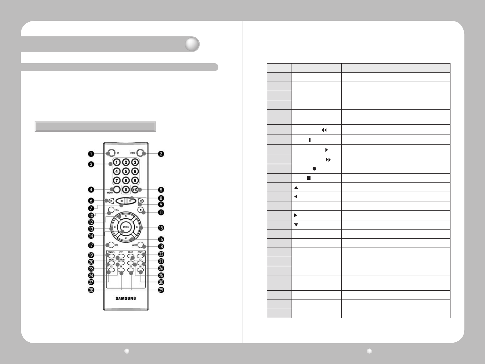
Buttons on the Remote Control
Figure 2.6.1 Remote Control
No. Name Function
1ID Selects the unique ID.
2FUNC Starts Function mode.
3Channel buttons Changes channels.
4MENU Switches to the on-screen display menu.
5+10 Use this button to select a channel number from 10 to 16;
for Channel 16, press +10 and then 6.
6FAST REWIND ( ) Fast reverses playback.
7PAUSE ( ) Pauses playback.
8FORWARD PLAY ( ) Forwards playback.
9FAST FORWARD ( ) Fast forwards playback.
10 RECORD ( ) Starts and stops manual recording.
11 STOP ( ) Stops playback.
12 Moves cursor up in the OSD menu.
13 Moves cursor left in the OSD menus.
14
↵
(Enter) Saves settings and executes a function.
15 Moves cursor right in the OSD menus.
16 Moves cursor down in the OSD menus.
17 ESC Cancels settings or goes up in the menu.
18 AUTO Switches to automatic display mode.
19 STATUS Displays system setup information.
20 PTZ Switches to PTZ mode.
21 MULTI Changes split-screen sections for live video or playback.
22 COPY Displays the Copy menu and saves recorded video to an
external storage device (USB).
23 MON Changes screen to spot monitor.
24 SEARCH Displays the Search menu.
25~30 F1~F6 Reserved for future use.
Digital Video Recorder User Guide
16
Digital Video Recorder User Guide
17
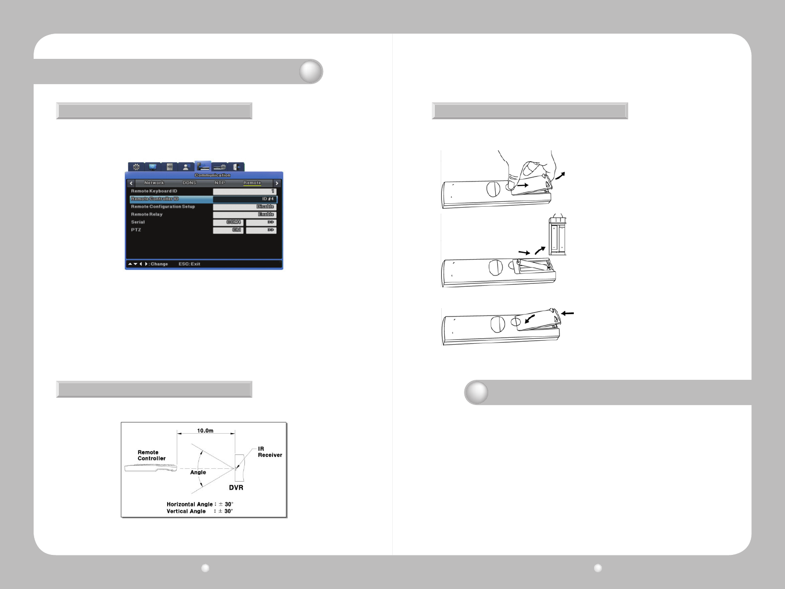
Setting the SVR-1670’s ID for the Remote Control
You can controlupto 16SVR-1670sfrom one remotecontrolbycreatinguniqueIDs for each
SVR-1670.
· Setting the ID for the remote control device
1. From the OSD, select the Network menu.
2. Select the Remote submenu.
3. For the Remote Controller ID option, select an ID value. This will become the ID for the remote device
you plan to use.
· Setting the ID for the remote control device
To select a specific SVR-1670, press the ID button on the remote controller repeatedly until you hear
a buzzer for 2 seconds. After the buzzer, the SVR-1670 starts responding to the remote controller’s
commands.
Chapter 2. SVR-1670 Description
Figure 2.6.2 Remote Control ID
Usable Range of Remote Control
Changing Batteries
Figure 2.6.3 Remote Control Device’s Usable Range
1. To remove the rear battery cover, press it
forward.
2. Check the battery contacts inside the remote
controller: + and –. Insert each battery matching
the battery contacts and battery poles.
3. Reinsert the battery cover.
The Remote Control takes AAA-sized batteries. Here is how to insert new or replacement
batteries:
Chapter 3. Hardware Installation
Thischapterdescribeshowtoinstallthehardware.ItincludesinstructionsforinstallingtheSVR-1670inarackor
onadesktop;connectingdevicestotheSVR-1670includingcameras,monitors,sensors,andrelays;andhandling
and preparing wiring.
The information is presented in these sections.
•3.1InstallingtheSVR-1670inaRack
•3.2WorkingwithInput/OutputTerminals
•3.3BasicConnectionstotheSVR-1670
•3.4ExtendedConnectionstotheSVR-1670
•3.5RemoteMonitoringandControl
•3.6HardDiskDriveInstallation
Figure2.6.3showsananglewhentheremotecontrollerispointedtotheDVRremotecontroller
receiver.
Digital Video Recorder User Guide
18
Digital Video Recorder User Guide
19
Chapter 3. Hardware Installation
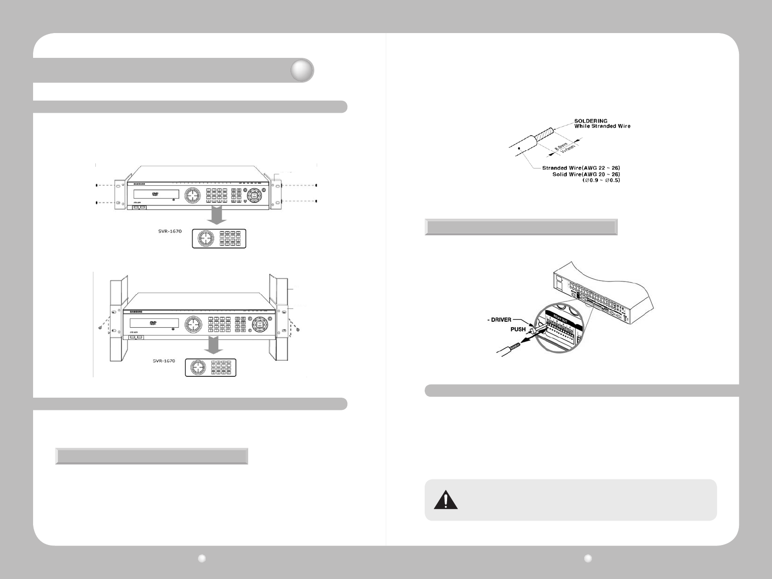
3. 1 Installing the SVR-1670 in a Rack
3. 2 Working with Input/Output Terminals
TousetheSVR-1670safely,pleaseinstalltheSVRinarackusingtheenclosedrackmounts.Follow
theseinstructionstoinstalltheSVR-1670inarack.
1. Attach the enclosed rack mounts to the product.
2. Attach the enclosed rack mounts to the product.
This section discusses the proper handling of wires and cables when connecting sensors, relays and
otherdevicestotheSVR-1670.
You might need to prepare cables before connecting them to terminal blocks. Different wire gauges
are needed for stranded wire or solid wire. Prepare the end of the wire by removing the following
amounts of insulation:
· Stranded wire : Strip 1/3 ~ 1/2" (8 ~ 10mm) of insulation off the end of the wire and solder it together.
Use AWG 22 ~ 26 wire.
· Solid wire : Strip 1/3 ~ 1/2" (8 ~ 10mm) of insulation off the end of the wire. Use AWG 20 ~ 26.
Handling Cable Ends
Figure 3.2.1 Preparing Cables for Terminal Blocks
Figure 3.2.2 Inserting and Removing Wires
This section explains how to connect devices to the SVR-1670, within the following subsections:
•BasicConnectionDiagram
•ConnectingCameras
•ConnectingaMonitor
•ConnectingAudio
•ConnectingthePowerCable
3. 3 Basic Connections to the SVR-1670
Always turn off the SVR-1670 and disconnect the power cord from its power source before
you connect devices to the SVR-1670.
When inserting or removing a wire from a terminal block, do it while holding down the terminal block
with a screw driver.
Wire Insertion and Removal
Rack Mount
Rack
Rack Mount
Digital Video Recorder User Guide
20
Digital Video Recorder User Guide
21
Basic Connection Diagram
Connecting Cameras
Chapter 3. Hardware Installation
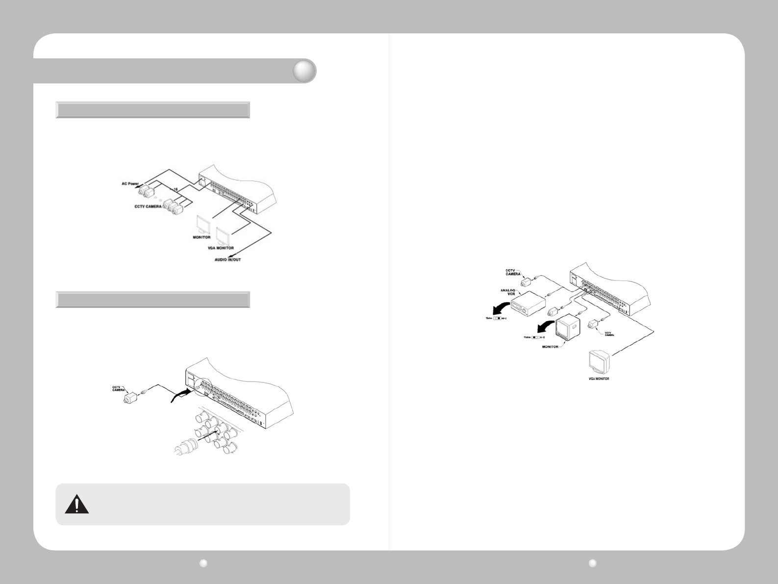
Thefollowingcongurationdiagramdepictsabasicsamplecongurationthatincludecameras,
monitors, sensors, and relays. These diagrams are representative only and are not intended to
depicttheonlypossiblecongurationsfortheSVR-1670.
1.EnsurethattheSVR-1670isnotconnectedtoalivepowersource.
2.Using video cable, connect up to 16 standard CCTV cameras to the SVR-1670. Follow the
instructionsprovidedwiththecamerastoconnectthemtoanexternalpowersource.
Figure 3.3.1 Sample Connection Diagrams
Figure 3.3.2 Connecting Cameras to the SVR-1670
Figure 3.3.3 Video Input and Output Connections
Never connect both NTSC and PAL cameras to the SVR-1670 at the same time. The SVR-
1670 recognizes only one camera type at a time.
ThefollowingdefaultsettingsareassignedtocamerasthatareconnectedtotheSVR-1670.
·
Video input type, which is determined by the device that is connected to the lowest channel number. For
example, if there are five cameras connected to the SVR-1670 and the lowest channel number in use is
6, then the SVR-1670 will set the video input type to match the camera connected to channel 6.
· Terminal resistance, which the SVR-1670 automatically sets at 75Ω when one video input port is in
use. When a lower video input port is also connected, the SVR-1670 automatically separates the terminal
resistance between 75Ω and Hi-Z (high impedance).
About Video In and Out Connections
The SVR-1670 video input/output connections are “Loop through." Their connection status is detected
automatically to set terminal resistance.
For example, when only video input is connected, terminal resistance is set internally to 75Ω. When
video input and output are connected, terminal resistance is set to Hi-Z. This setting for input and output
connections sets the external output device to 75Ω for terminal resistance.
Digital Video Recorder User Guide
22
Digital Video Recorder User Guide
23
Chapter 3. Hardware Installation
Connecting a Monitor
Connecting Audio
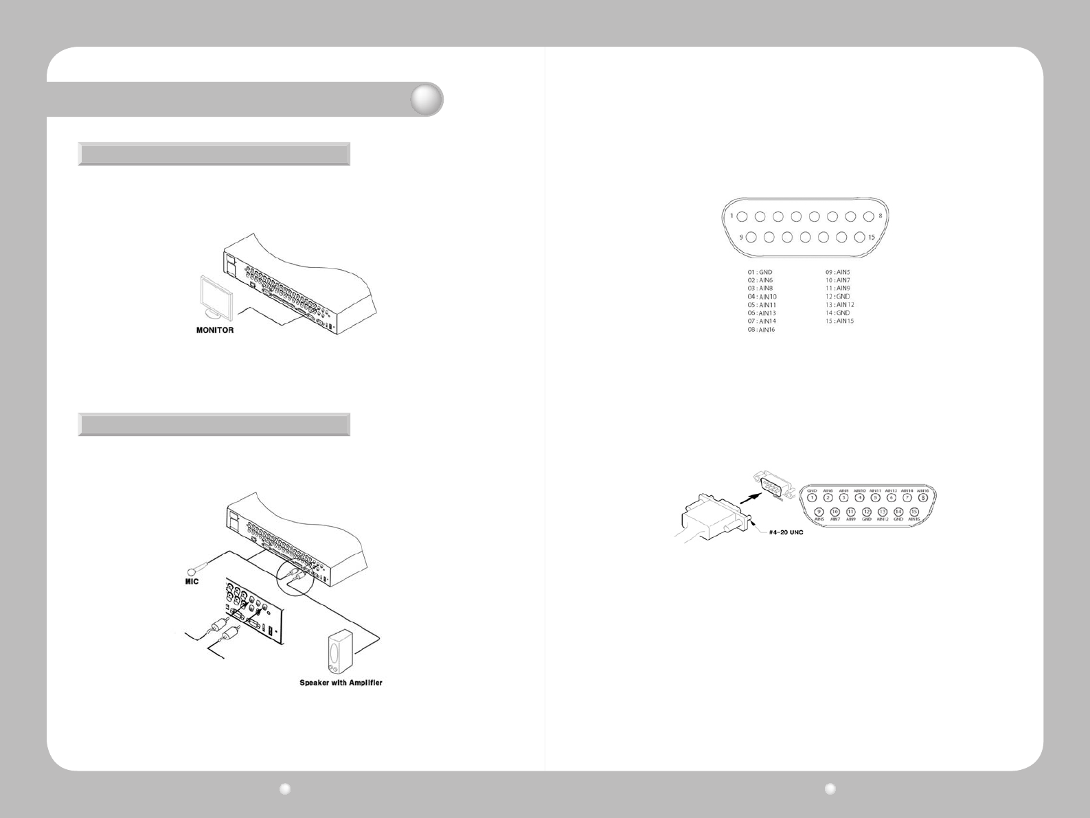
1.EnsurethattheSVR-1670isnotconnectedtoalivepowersource.
2.Usingamonitorcable,connectamonitorormonitorstotheSVR-1670.
1.EnsurethattheSVR-1670isnotconnectedtoalivepowersource.
2.UsingRCAaudiocablesorD-SUBcables,attachamicrophoneandspeakerstotheSVR-1670.
3.RefertoFigure3.3.6whenconnectingdeviceswithD-SUBcables.
3.Connectthemonitor’spowercordtothemonitorandtoanexternalpowersource.
Figure 3.3.4 Connecting Monitors to the SVR-1670
Figure 3.3.5 Connecting Audio to the SVR-1670
Figure 3.3.6 The Audio Pin Assignments
Figure 3.3.7 Audio Input and Output Connections
Audio In/Out Connections
There are four RCA audio in and 12 D-SUB audio in connections. All 16 audio sources can be monitored
through a single output. The 12 D-SUB audio inputs use terminals 2 through 15 and are connected as
shown in Figure 3.3.7.
Digital Video Recorder User Guide
24
Digital Video Recorder User Guide
25
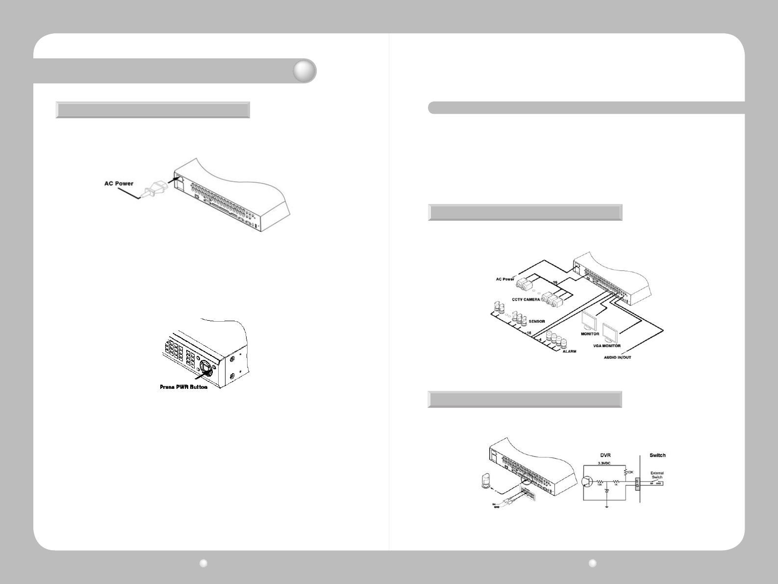
Connectthepowercableasshowninthefollowinggure.
TheSVR-1670startsautomaticallywhenthepowerisconnected.
Figure 3.3.8 Connecting a Power Cord
Figure 3.3.9 Turning On the SVR-1670
Connecting the Power Cable
Chapter 3. Hardware Installation
·
To turn off the SVR-1670, press and hold the power button for 5 seconds, then choose “Yes” when the
power-off dialog appears.
· You can also unplug the power cable from the power outlet to turn off the SVR-1670.
This section explains how to connect additional devices to the SVR-1670. It includes the following
subsections :
•ExtendedConnectionDiagram
•SensorConnectionsandSettings
•RelayConnections
•D-I/O(Digital-I/O)ConnectionsAndSettings
•Serialcommunicationterminalconnections
Thefollowingpictureisanexampleofconnectingtheproductwithaseriesofexternaldevices:
sensorinputs,relayoutputs,D-I/O,serialcommunicationterminals,andstorage.Pleasereferto
thisexampleforyourinformation.
Extended Connection Diagram
Figure 3.4.1 Extended Connection Diagram
ConnectsensorstoS1throughS16.Sensorscanbeconnectedwithdrycontacts.
Figure 3.4.2 Sensor Connections
Sensor Connections and Settings
3. 4 Extended Connections to the SVR-1670
Digital Video Recorder User Guide
26
Digital Video Recorder User Guide
27
Thesensorspecicationsareasfollows.
Specication
No. of inputs 16 transistor input
Input types N.C, N.O support
Support Sensor Dry contact sensor
Connection method Insert stripped wire end into terminal block
Electric
capacity
Pulse width of usable
input Minimum 500ms
Output power Typical DC 12mA
Chapter 3. Hardware Installation
ConnectrelaystoR1throughR4asillustratedinthegurebelow.TheillustrationinFigure3.4.3
shows how to connect a warning light.
Figure 3.4.3 Relay Connections for a Warning Light
Relay Connections
Thealarmspecicationsareasfollows.
Specication
No. of outputs 4 relay outputs
Output type Dry contact
Connection method Insert stripped wire end into terminal block
Rated
current
DC 24V 1A
AC 125V 0.5A
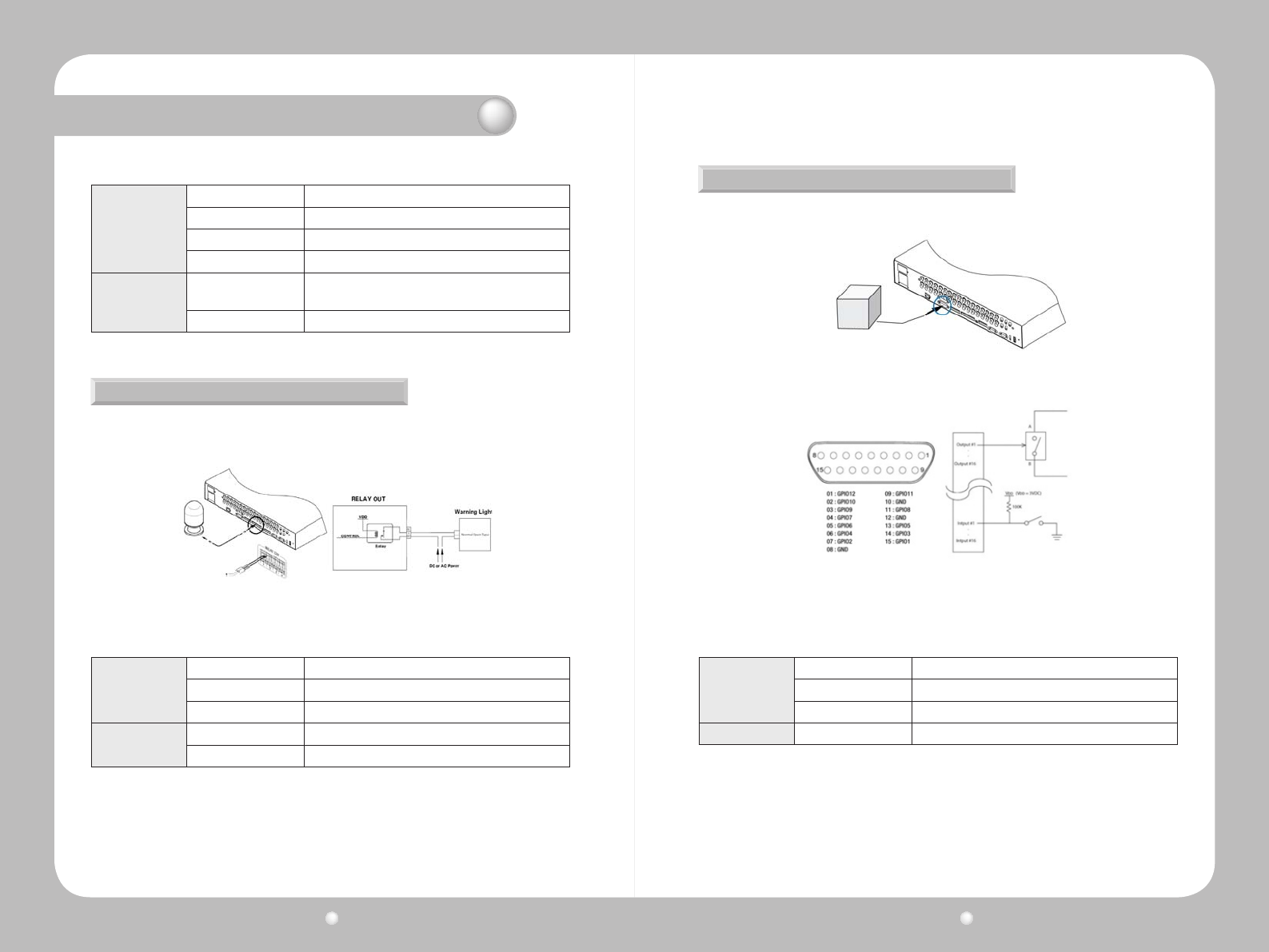
ConnectadigitaldevicetotheD-I/Oinputandoutputterminals.
D-I/O Connections And Settings
Figure 3.4.4 D-I/O device connection
Figure 3.4.5 Digital Input/Output Connections
D-I/O
TheD-I/Ospecicationsareasfollows.
Specication
No. of inputs/outputs 12
Output type DC 3V output
Connection method Connect stripped wire end with 15 pin D_SUB.
Ratedcurrent DC 3.3 V
Digital Video Recorder User Guide
28
Digital Video Recorder User Guide
29
Chapter 3. Hardware Installation
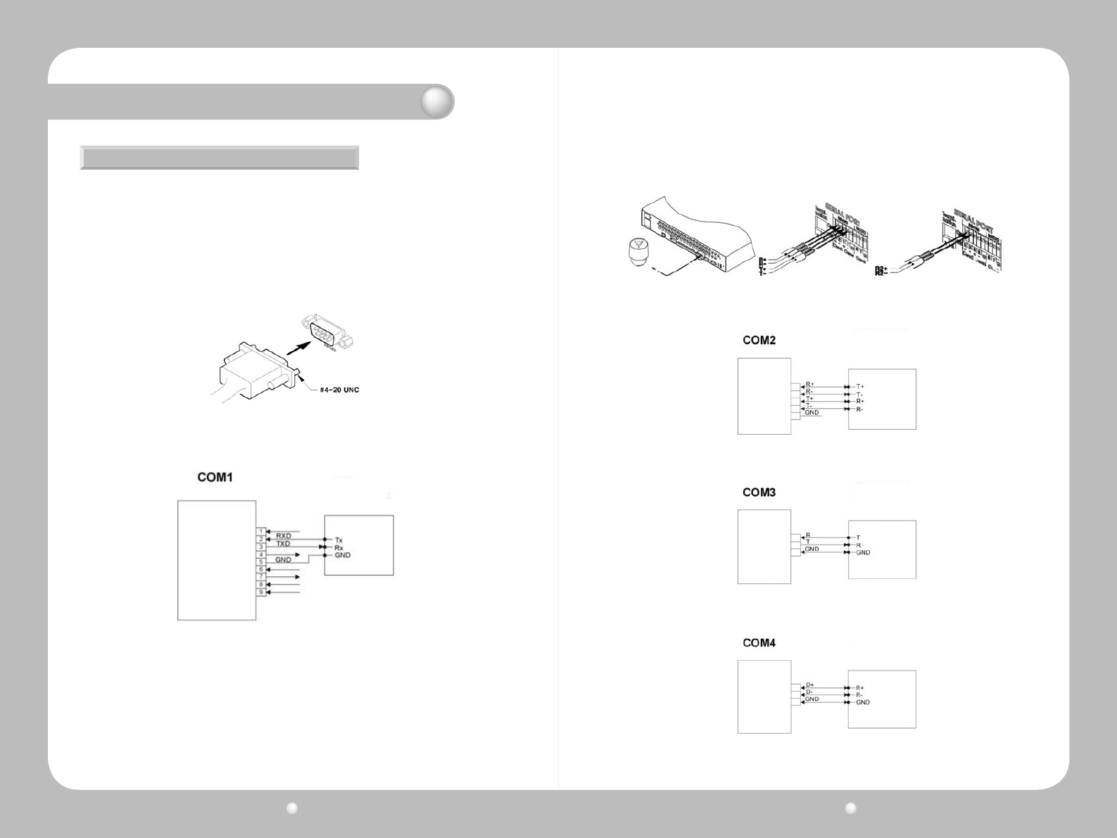
SeveraltypesofdevicescanbeconnectedtotheSVR-1670throughserialports.Accesscontrol,
ATM,andPoStransactiondatacanbetransmittedthroughtheCOM1port.PTZcamerascanbe
connectedandoperatedthroughtheCOM2orCOM4ports.
Connecting Access Control, ATM, or PoS Devices
UseanRS-232cabletoconnecttextandvideodatafromPoSorATMterminalsthroughtheCOM1
port.COM1/RS-232(9-pinD-SUB)isusedtoreceivetextdata.
Serial communication terminal connections
Figure 3.4.6 ATM, PoS, Access Control Connections
Figure 3.4.7 COM1 Connection (RS-232)
Connecting PTZ Cameras to the COM Ports
UseRS-422orRS-485ports(COM2orCOM4).
· Serial port connection terminals are also supported.
·PTZcamerasfortheSVR-1670canbeconnectedthroughtheCOMport,andsupportedmodels
conguredthroughtheonscreendisplaymenu.
Text
Keyboard
ThefollowingguresillustratehowtoconnectPTZcamerasthroughtheRS-422/485port(COM2/
COM4)andhowtoconnectotherdevicesthroughtheserialportconnectionterminals.
Figure 3.4.8 PTZ Camera Connection (COM2 )
Figure 3.4.9 COM2 Connection (RS-422/485)
Figure 3.4.10 COM3 Connection (RS-232)
Figure 3.4.11 COM2 Connection (RS-485)
Keyboard
PTZ
Keyboard
PTZ
Keyboard
PTZ
Digital Video Recorder User Guide
30
Digital Video Recorder User Guide
31
Chapter 3. Hardware Installation
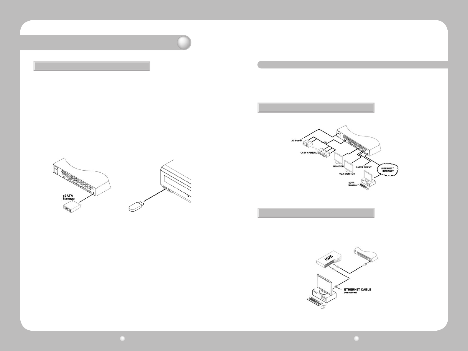
YoucanconnectaneSATAexternalharddiskdriveandaUSBmemorydevicetotheSVR-1670.
OneeSATAexternalstoragedevicecanbeconnectedthroughtheeSATAportonthebackpanel
oftheSVR-1670toexpandstoragetoamaximumof8TB.TheeSATAportsupportstheSamsung
TechwinSVS-5ReSATAexternalharddiskdrive.
Connecting an eSATA Device
TurnofftheSVR-1670beforeyouconnectanexternaldevicetoit.
External storage connections
1.After you turn off the SVR-1670, use the eSATA port on the back panel of the SVR-1670 to
connectanSVS-5Rexternalharddiskdrive.
2.Attachapowercordtothedriveandconnectittoanexternalpowersource.Ifnecessary,turn
ontheeSATAdrive.
3.TurnontheSVR-1670.
Figure 3.4.12 Connecting an eSATA Drive Figure 3.4.13 External Device Connections
This section describes how to congure remote access to the SVR-1670. It contains the following
subsections.
•Internet/IntranetConnectionDiagram
•EthernetConnections
ThefollowingexampleisawiringdiagramfortheSVR-1670tocontrolitremotelyovertheinternet
or intranet.
Internet/Intranet Connection Diagram
Figure 3.5.1 Internet Connection
Ethernet Connections
FollowthesestepstoconnectanEthernetcabletotheSVR-1670:
1.TurnofftheSVR-1670.
2.ConnectoneendoftheEthernetcabletotheSVR-1670andtheotherendtoahuborrouter.
Figure 3.5.2 The Ethernet Connections
3. 5 Remote Monitoring and Control
Digital Video Recorder User Guide
32
Digital Video Recorder User Guide
33
3. Turn on the hub or router.
4.TurnontheSVR-1670.
To prevent damage to the SVR-1670, wait to turn the power on until after you have connected
the Ethernet cable.
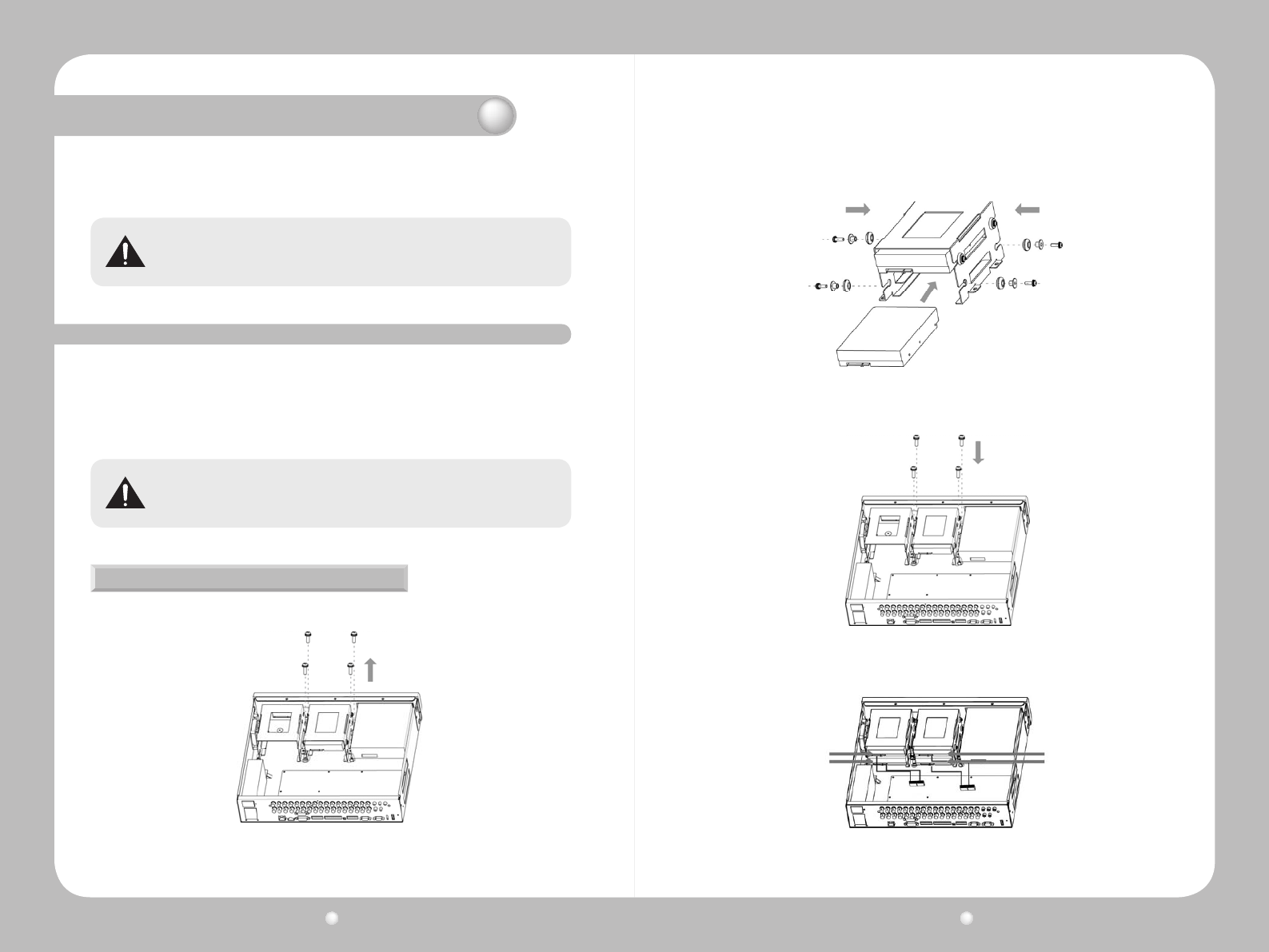
Always turn off the SVR-1670 and unplug the power cable before you attach or remove a hard
disk drive. Disconnect any devices that are connected to an external power source.
This section describes how to work with a hard disk drive, in the following subsections :
•InstallingaHardDiskDrive
•EnablingaHardDiskDrive
•RemovingaHardDiskDrive
•DisablingaHardDiskDrive
3. 6 Hard Disk Drive Installation
Installing a Hard Disk Drive
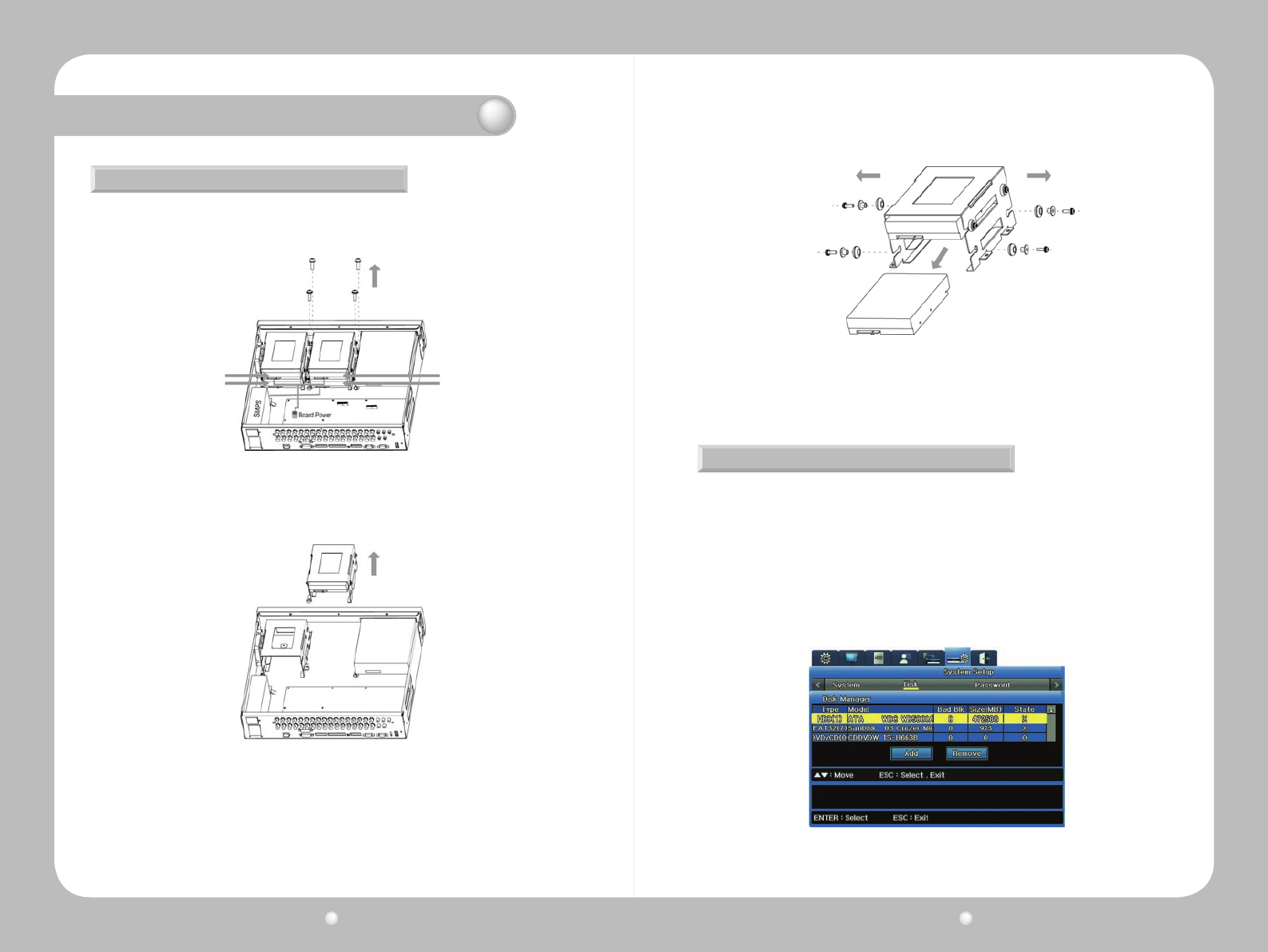
1.Opentheuppercoveroftheproduct,andthenremovethefourscrewsthatconnectthehard
disk drive bracket and main unit.
Figure 3.6.1 Removing Screws that Connect the SVR-1670 & Hard Disk Drive Bracket
Chapter 3. Hardware Installation
A
AD
BC
C
BD
2. Lift up the hard disk drive bracket, and then insert a hard disk. Fasten the disk to the bracket
usingtheenclosedxturescrews,asshowninthepicturebelow.
3.ReattachtheharddiskdrivebrackettotheSVR-1670mainunit.
4.Oncethebracketissecurelyattached,connecttheSATAcable.
Figure 3.6.2 Inserting Hard Disk to the SVR-1670
Figure 3.6.4 Connecting SATA cable
Figure 3.6.3 Reattaching Hard Disk Drive Bracket to the SVR-1670
Digital Video Recorder User Guide
34
Digital Video Recorder User Guide
35
A
AD
BC
C
BD
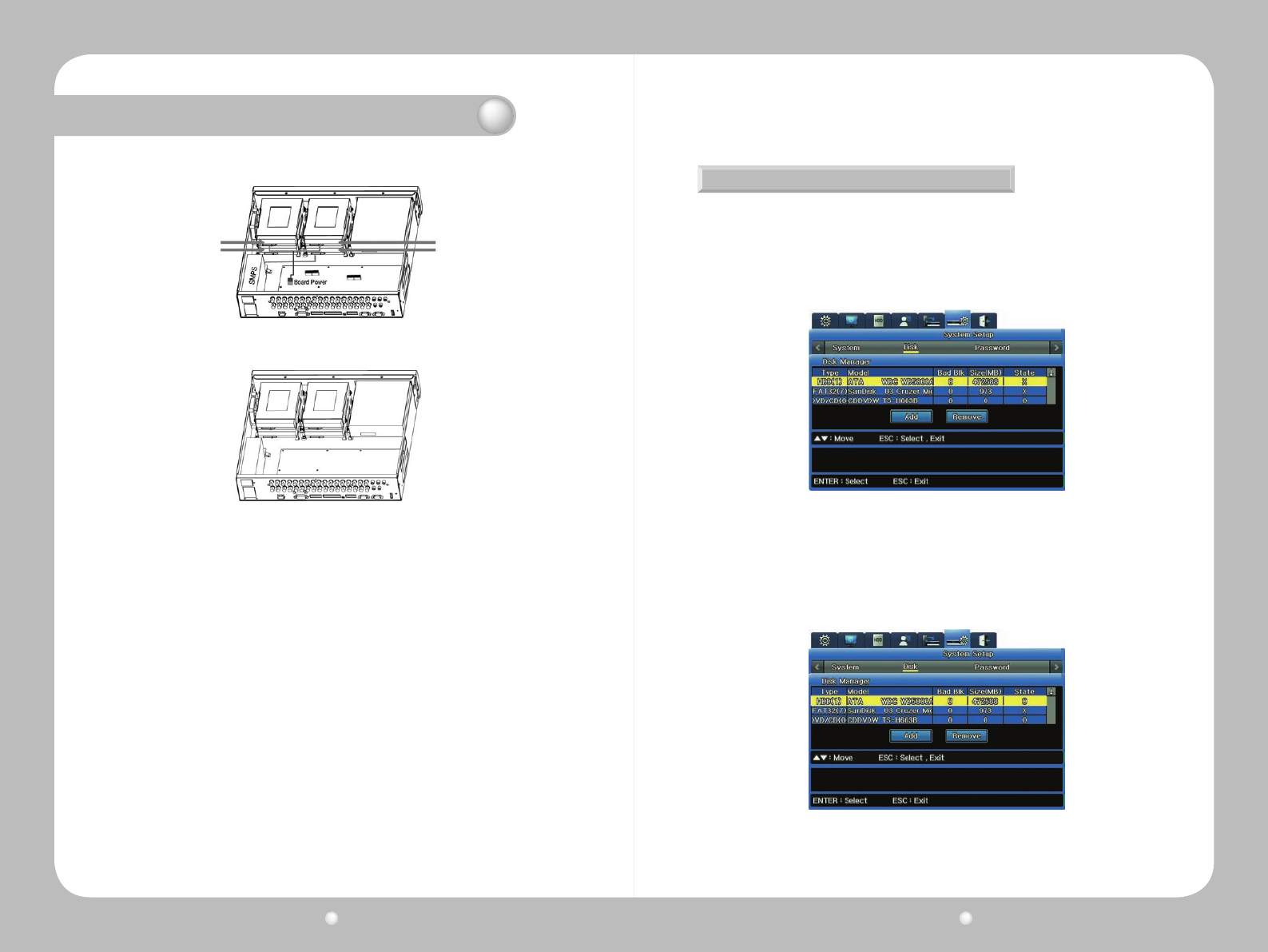
5.ConnecttheSMPS(switchedmodepowersupply)powercable.
6.ClosetheuppercoverontheSVR-1670,andthenreconnectalldevicesthatwereremovedfor
the hard drive installation.
Now,itistimetocongureandactivatetheharddiskdrive.
Figure 3.6.5 Connecting SMPS Power Cable (Change the Image)
Figure 3.6.6 The SVR-1670 Connected with Maximum Number of HDDs
Chapter 3. Hardware Installation
Enabling a Hard Disk Drive
Toenablethenewlyattachedharddiskdrive,youmustchangeitsavailabilityto"O"onthe
SVR-1670’sDiskManagermenu.
1.FromtheOSD,selecttheSystemSettingsmenu.
2.SelecttheDisksubmenu,andthen,onit,selectDiskManager.
-ThenewlyinstalledharddiskdriveappearsinthelistalongwithOandXundertheState
category.
3.TochangetoEnabledstatus,selecttheharddiskdrivetoconnectandthenpressESCtoexit
theDiskSelectionmenu.Toenabletheharddiskdrive,selectAddandthenpressEnter.You
can add the hard disk drive to store data.
Figure 3.6.7 Disk Manager Menu Showing Disabled Hard Disk Drive
Figure 3.6.8 Disk Manager Menu Showing Enabled Hard Disk Drive
Digital Video Recorder User Guide
36
Digital Video Recorder User Guide
37
To detach a hard disk drive, follow the instructions below:
1.UnplugtheSATAandpowercables.RemovethescrewsthatconnecttheSVR-1670mainunit
and the hard disk drive bracket.
2. Lift up the loose hard disk bracket.
3.Removexturescrewsonthebothsidesoftheharddiskandthebracket.Storetheremoved
xturescrewssafely,soyoucanusethemtoconnectaharddiskagainlater.
4.Pushtheharddiskdriveoutfromthebracket.
Removing a Hard Disk Drive
Figure 3.6.9 Removing Screws that Connect the SVR-1670 and Hard Disk Drive Bracket
A
AD
BC
C
BD
Figure 3.6.10 Lifting Hard Disk Drive Bracket from the SVR-1670
Chapter 3. Hardware Installation
Now,itistimetocongureanddisabletheharddrivefromthesystem.
Figure 3.6.11 Removing Hard Disk Drive
Disabling a Hard Disk Drive
Todisabletheremovedharddiskdrive,youmustchangeitsavailabilityto"X"ontheSVR-
1670’sDiskManagermenu.
1.FromtheOSD,selecttheSystemSettingsmenu.
2.SelecttheDisksubmenu,andthen,onit,selectDiskManager.
3.Selecttheremovedharddiskdrive,andthenpressESCtoexitthemenu.SelectRemove,and
thenpressEnter.
4.Attheconrmationmessage,select“Yes”toremovetheharddiskdrivefromthelist.
Figure 3.6.9 Disk Manager Menu Showing Disabled Hard Disk Drive
Digital Video Recorder User Guide
38
Digital Video Recorder User Guide
39
This chapter provides information about using the two graphical user interfaces for the Samsung
SVR-1670DVR—theOn-ScreenDisplayandtheFunctionmenu.
TheOn-ScreenDisplay(OSD)providesaccesstoallSVR-1670featuresandsettingsthrougha
series of menus, submenus and options.
TheFunctionKeymenuprovidesaccesstoallSVR-1670functions,suchasoperationofcameras
and manipulation of recorded video, through a main menu with icons.
YoucanaccessboththeOSDandFunctionmenuusingthebuttonsontheSVR-1670frontpanel,
the mouse, or by using the remote control device.
The information is presented in these sections :
▶4.1WorkingwiththeOn-ScreenDisplay
▶4.2WorkingwiththeFunctionMenu
You will use the OSD to set up, congure and operate the SVR-1670. The section discusses how to
work with the OSD and covers the following topics :
• AccessingtheOSD
• UnderstandingtheMenuStructure
• UsingtheOn-ScreenKeyboard
• Setting the Date and Time
• SavingYourChangesontheOSD
4. 1 Working with the On-Screen Display
Accessing the OSD
OSD Screen Elements
ToaccesstheOSD,youcaneither:
·PresstheMENUbuttononthefrontpanel.Tocloseit,presstheESCbutton.
·PresstheMenubuttonontheremotecontrol.Tocloseit,presstheESCbutton.
·Pressthe“Home”iconontheFunctionmenu.Tocloseit,presstheESCbutton.
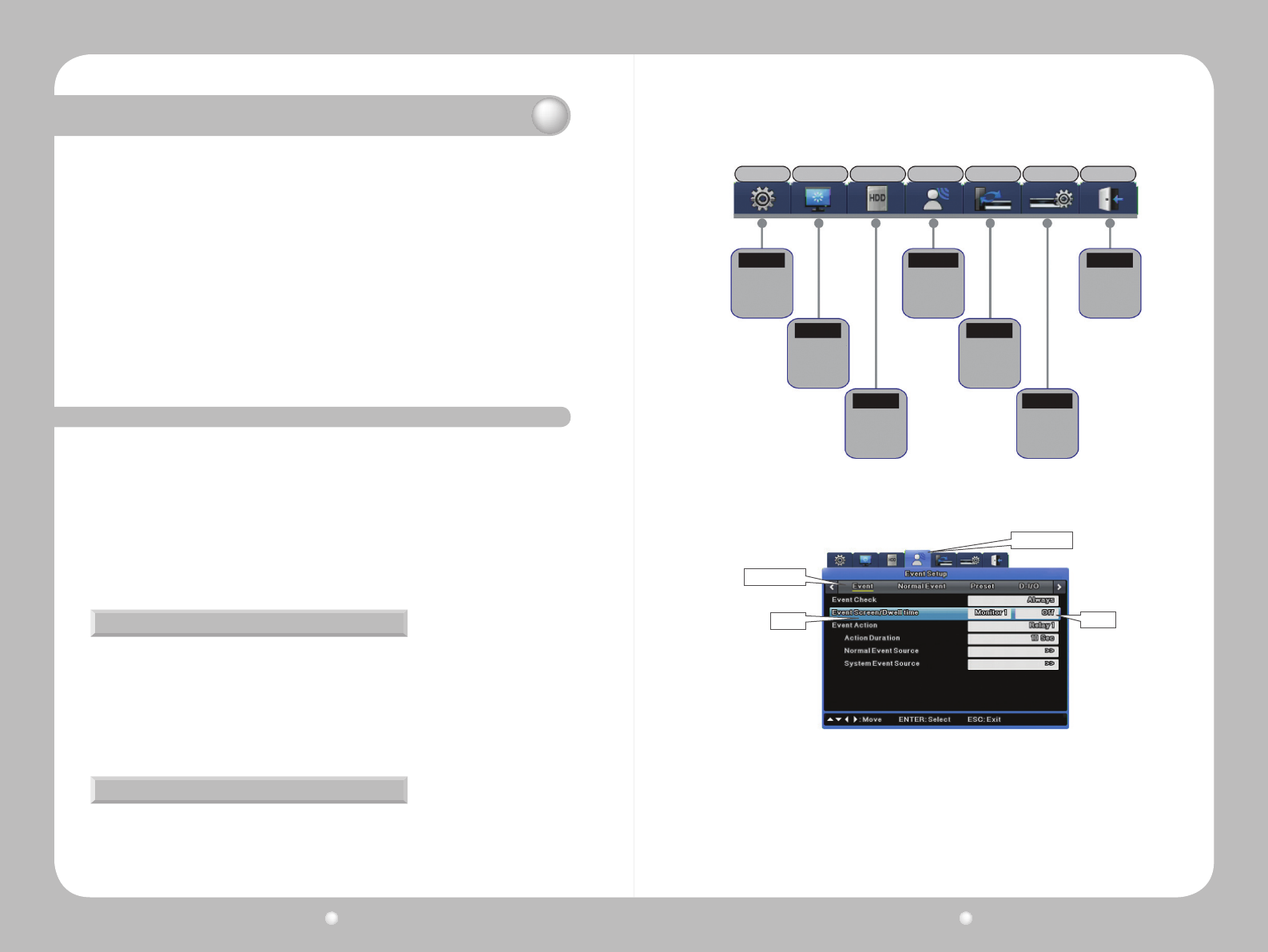
TheOSDcontainsarowoftabsatthetopwithiconsrepresentingsevenmenus—QuickSetup,
Display,Record(HDD),Event,Communications,SystemSetup,andExit.
Chapter 4. Navigation: On-Screen Display and Function Menus
Figure 4.1.1 The On Screen Display
Quick Setup
Quick
Quick Setup
Program
Event Check
Language
Time
Audio Recording
Channel Display
Monitor1
SPOT
Record
Program
Event
Normal
Preset
D-I/O
System
Disk
Password
Save
Do not save
Network
DDNS
NTP
Remote
Streaming
IP Filter
Display
Record
Comm.
Exit
Display Setup
Record Setup
Network Setup
ExitEvent Setup
Event
System
System Setup
Eachmenuhasagraytitlebarwithsubmenus,demonstratedinFigure4.1.2:
Noticethatonthesubmenu,optionsarelistedontheleftsideofthescreen,withsettingstothe
right.
AsyouworkontheOSDyouwillquicklylearnhowtouseyourpreferredmethodofmovingfrom
menus, options and settings. This table gives you the basic instructions you need to know to get
started.
Figure 4.1.2 The OSD Menu Structure
Submenu
Setting
Option
Menu tab(Icon)
Digital Video Recorder User Guide
40
Digital Video Recorder User Guide
41
Chapter 4. Navigation: On-Screen Display and Function Menus
PlaceinOSD Description/Navigation
Menu
Current menu tab is highlighted in blue.
Move between menus in any of these ways :
· DVR front panel : Use the left and right buttons, then press PLAY/ENTER to make
your selection.
· Mouse : Press the mouse’s left key to make your selection.
· Remote Control : Use the left and right arrow buttons, and then press Enter to
make your selection.
To select a different menu or to exit the OSD, press Exit.
Submenu
Current submenu is displayed with a yellow underline.
To go across submenus :
· DVR front panel : Use the left and right buttons, then press PLAY/ENTER to make
your selection.
· Mouse : Press the mouse’s left key to make your selection
· Remote Control : Use the left and right arrow buttons, and then press Enter to
make your selection.
To go to a different menu, press ESC.
Option
Current option is highlighted in blue.
To go between options :
· DVR front panel : Use the left and right buttons, then press PLAY/ENTER to make
your selection.
· Mouse : Use the mouse wheel to scroll or press the left button on the mouse to
make a selection.
· Remote Control : Use the left and right arrow buttons, and then press Enter to
make your selection.
To go to a different submenu, press ESC.
Setting
Current or default setting is displayed in gray text field.
A double forward caret >> means there is an additional submenu, with more
settings for you to choose.
To adjust a setting :
· DVR front panel : Use the left and right buttons.
· Mouse : Scroll with the mousewheel and Double-click to select a sub menu.
· Remote Control : Use the left and right arrow buttons.
To edit data :
· For a numeric value, use the left/right or up/down arrow buttons.
· For text, use the on-screen keyboard.
Press ESC to move away from the setting.
As you type, the text you enter
appears here for you to edit.
Using the On-Screen Keyboard
Saving Your Changes on the OSD
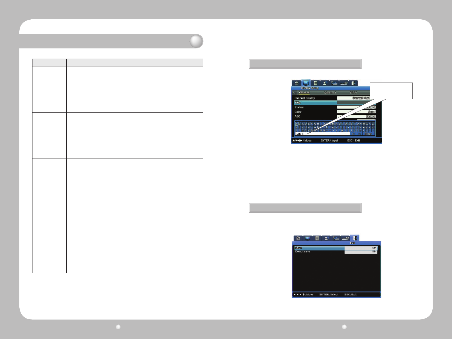
Usetheon-screenkeyboardtoinputtext.
BesuretosaveyourchangeswhenyouexittheOSD.Wheneveryoumakechangestoanoption
ontheOSD,youmustsavethemsotheygointoeffect.
Figure 4.1.3 The On-Screen Keyboard
Figure 4.1.4 The Exit Menu
Toentertextontheon-screenkeyboard:
·Usetheleft/rightorup/downarrowkeystochoosecharacters.
·Usebackarrow← to backspace, and forward arrow → to insert a space.
·PresstheENTERkeytoexitthekeyboardandsaveyourtext.
Digital Video Recorder User Guide
42
Digital Video Recorder User Guide
43
To save your changes :
1.SelecttheExittabontheOSD.
2. Select “Save”.
3.Whentheconrmationmessageappears,select“Save”.
·Ifyoudecideyoudonotwanttosavechanges,select“Don’tsave.”.
From the Function Menu you can access the OSD, operate other DVR functions, and control camera
playback. This section explains how to access the FUNC menu, and what each icon on the menu
means.
4. 2 Working with the Function Key Menu
Accessing the Function Menu
Understanding the Menu Structure
To access the Function menu, use any of these methods :
·PresstheFUNCbuttonontheDVRfrontpanel.Tocloseit,presstheESCbutton.
·Right-clickthemouse.Tocloseit,right-clickagain.
·PresstheFUNCbuttonontheremotecontrol.Tocloseit,presstheESCbutton.
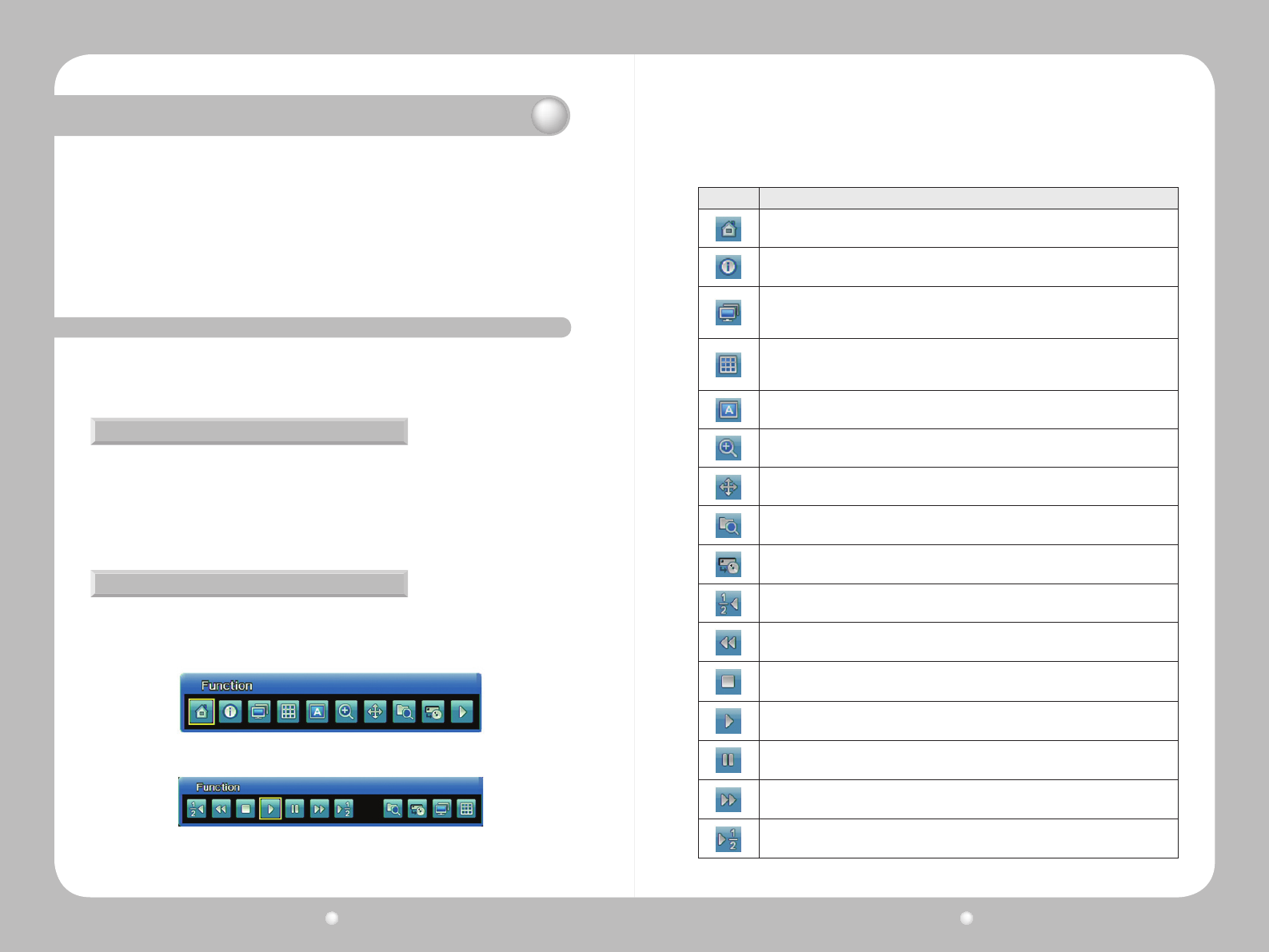
Two types of function key menus are provided: Live Function and Playback Function. The Live
FunctionmenucontrolsvariousfunctionsoftheSVR-1670whilePlaybackFunctioncontrols
video play options.
Figure 4.2.1 Live Mode Function Menu
Figure 4.2.2 Playback Mode Function Menu
Chapter 4. Navigation: On-Screen Display and Function Menus
Thefollowingtableexplainswhatfunctioniscontrolledbyeachicon:
Icon
Function
Opens the OSD. The FUNC menu closes and the OSD is available.
Displays a list of system information.
Select the Monitor you wish to view. This icon is set to toggle, which means each time you
select the icon, your view shifts to the next monitor for however many monitors you have
set up.
Displays the images to which you have channels. This icon is set to toggle, which means
each time you select the icon, your view shifts through the various display layouts available
(1x, 4x, 9x, 16x).
Begins camera Sequencing, if you have setup your channels to display live camera feeds
in sequence.
Goes to Zoom menu.
Begins Pan/Tilt/Zoom functions if you have a PTZ camera linked to the DVR.
Opens the Search submenu.
Opens the Copy submenu.
Rewinds recorded video at half speed.
Rewinds recorded video.
Stops playback of recorded video.
Plays recorded video.
Pauses recorded video.
Forwards recorded video.
Forwards recorded video at half speed.
Digital Video Recorder User Guide
44
Digital Video Recorder User Guide
45
ThischapterexplainstheQuickSetupmenu,fromwhichyoucansettherecordingmodeandthe
systemdateandtime.Youcanalsoturnoneventcheckingandaudio,andselectthelanguage
for the system to use.
This chapter information is presented in the following sections:
▶5.1WorkingontheQuickSetupMenu
▶5.2SettingtheRecordMode
▶ 5.3 Setting the Date and Time
You access the Quick Setup menu by clicking the Quick Setup tab on the OSD. This section
explains its options and settings.
5. 1. Working on the Quick Setup Menu
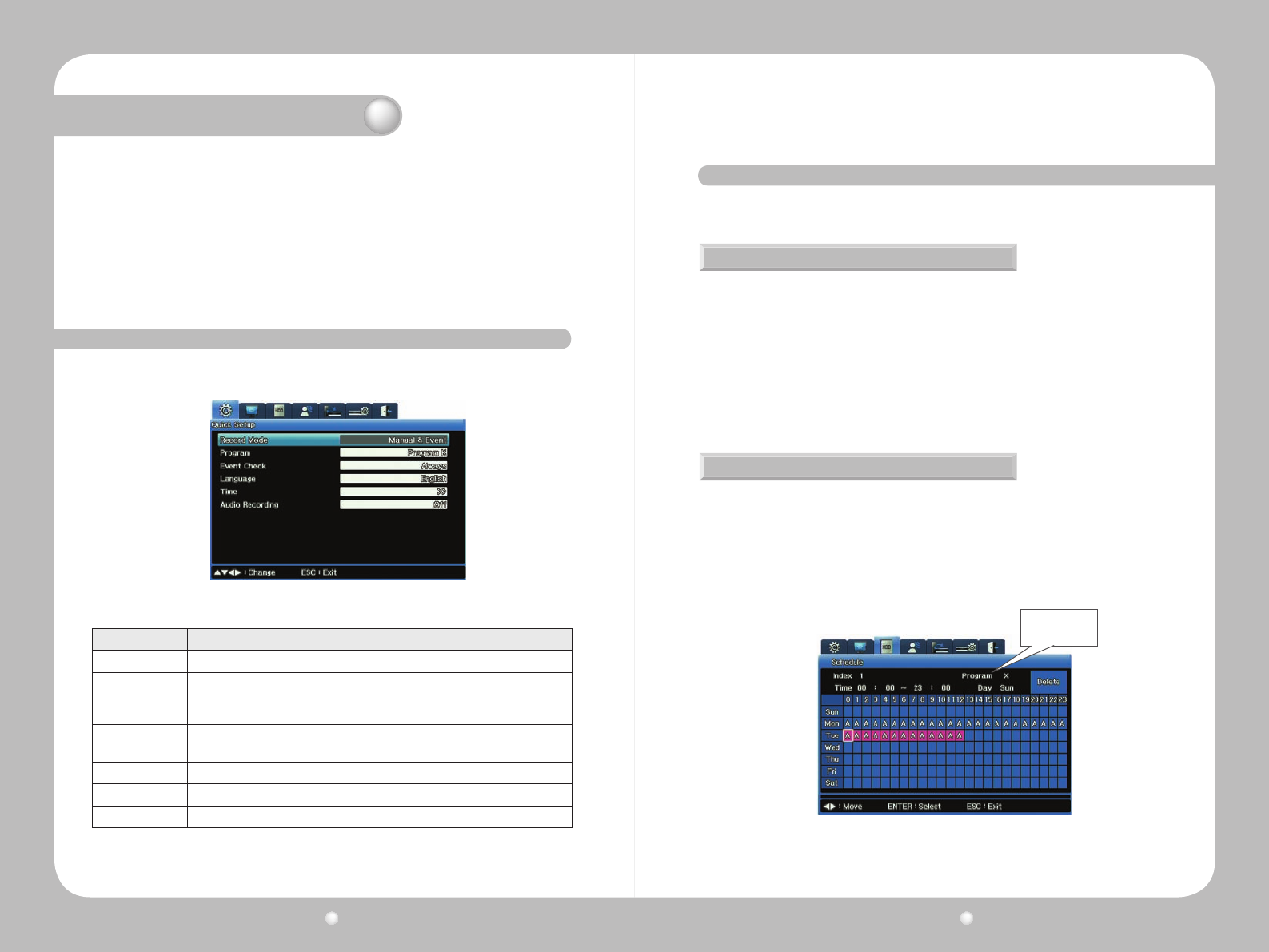
Figure 5.1.1 Quick Setup Menu
Option Settings
Record Mode Specify how you want to record: by Schedule & Event, or Manual & Event.
Schedule
Or
Program
If you select Schedule & Event as the record mode, this option is for the Schedule.
If you select Manual & Event as the record mode, this option is for Program.
Event Check When you want the system to check for events: Always, according to the Schedule
you selected, or Off (no checking performed).
Language The language you want to display on menus and screens.
Time Set the date and time by which the system is to run, record and timestamp data.
Record Audio Set to On or Off.
Chapter 5. Quick Setup
Select the
Program, A-Z
This section provides a brief discussion about the record mode settings of Schedule & Event and
Manual & Event
Manual & Event
Schedule & Event
YoucanconguretheproducttostartrecordingwhentheRECbuttononthefrontpanelis
pressed, or when a preset event occurs.
IfyousetManual&EventfortheRecordMode,youmustalsoselectaProgramfortheProgram
option.SettingsrunfromProgramAthroughProgramZ.
Toreview(oredit)thedenitionsofaProgram,gototheRecordSetup(akaHDD)menuonthe
OSDandselecttheProgramsubmenu.
Afteryou’veselectedManual&Eventanditsprogram,presstheRECbuttonontheDVR’sfront
paneltobegintherecording.TheReclightwillglowredduringrecording.
Youcanconguretheproducttostartrecordingonascheduleddateorwhenapresetevent
occurs.IfyouselectSchedule&Event,youneedtosetuptheschedule.
1. From the Schedule option, access the Schedule submenu. This menu is in a calendar format
showingeachdayoftheweekand24hourswitheachday.
2.OnthisSchedule,selectwhichProgramtorunonanygivenday,orhoursofthatday.
HereisanexampleshowingProgramAenteredastheprogramtorunonMondaysandon
TuesdaysfromMidnightuntilNoon.
Figure 5.2.1 Schedule Submenu from Quick Setup
5. 2. Setting the Record Mode
Digital Video Recorder User Guide
46
Digital Video Recorder User Guide
47
Chapter 5. Quick Setup
3.OnceyouhavecompletedtheRecordsetup,noticetheReclightontheDVR’sfrontpanel
ickersandthesymbolSdisplaystoshowthatallchannelsarerecordingasscheduled.
Setting the system time is very important for the validity of your recorded data. The date and time
you set governs all schedules your subsequently congure for the DVR. The date and time appear
on all monitor displays and on all timestamps for events.
5. 3. Setting the Date and Time
Plan carefully if you need to set the date and time!
Back up video before changing the time.
Do not change time setting while recording. Doing so can compromise the date stamping of
the recording.
To set the date and time, follow these steps :
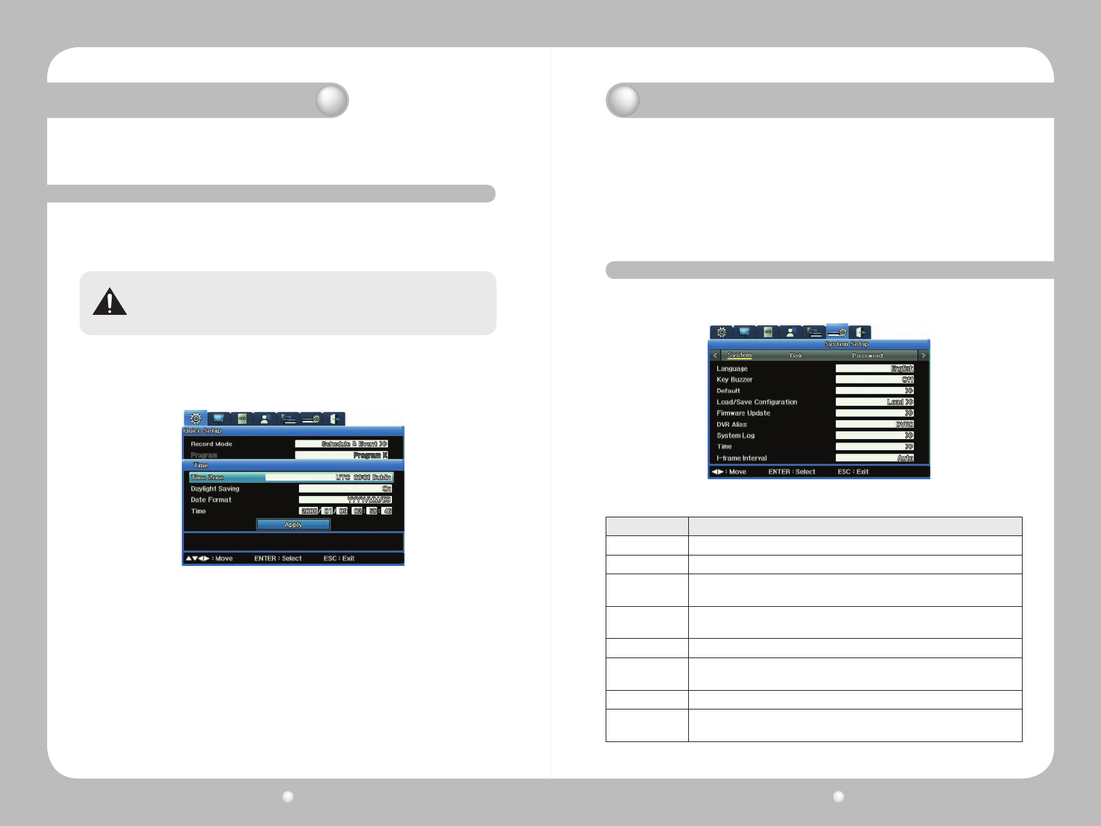
1.SelecttheTimeoptionfromtheQuickSetmenu.
2.Enterthetimezoneforthecameralocation.(ThedefaultsettingisUTC00:00Dublin.)
3. Set Daylight Savings to on or off. (The Daylight Savings option is only available if daylight
savingtimeisusedinthetimezoneyouselected.)
4.SelecttheDateFormatyouprefer.
-FormatsareYYYY/MM/DDorMM/DD/YYYYorDD/MM/YYYY.
5.SettheTimebyenteringdataineachoftheDateeldsandintheHour/Minutes/Seconds
elds.
6.ClicktheApplyDate/Timebuttontoconrmandsavethesettings.
·Whentheconrmationmessageappears,selectYesifyouwanttoconrmyourchangesto
thedate/timesetting.
Figure 5.3.1 System Time Submenu on Quick Setup
Chapter 6. Using the System Setup Menu
ThischapterprovidesinformationaboutthefeaturesontheOSD’sSystemSetupmenu,from
whichyousetupvarioussystem-widecontrolsfortheDVR
The information is presented in these sections :
▶6.1UsingtheSystemSetupOptions
▶6.2UsingtheDiskOptionsontheSystemSetupMenu.
▶6.3WorkingwithPasswordsandPermissions.
You access the System Setup menu by clicking its tab on the OSD. This section explains its four
submenus, their options and settings.
Figure 6.1.1 System submenu on the System Setup Menu
Option Settings
Language Select a language.
Key Buzzer
Select On if you want a buzzer to sound when you use the buttons on the front panel.
Default Select if you want to restore the factory default settings. At the warning message,
select “Yes” again to restore the settings.
Load/Save
Configuration
Select Save if you want to save settings to USB storage.
Select Load if you want to load stored settings from USB storage.
Firmware Update Select to update firmware from USB storage and connect it to the SVR-1670
DVR Alias Set a SVR-1670 alias; that is, give the SVR-1670 its own name such as “Main
Floor,” “Headquarters,” or “Fred.”
System Log Displays a log, by time, of various events within the system
Time Set the system time. You can set the time in two places: here and on the Quick
Start menu.
6. 1 Using the System Setup Options
Digital Video Recorder User Guide
48
Digital Video Recorder User Guide
49
Chapter 6. Using the System Setup Menu
Updating Firmware
Working with the System Log
Reviewing the System Log
Youcanupdatethermwareyouareusingforvideoaccessandmanagement.
1.InsertaUSBdrivecontainingrmwareupdatelestooneoftheUSBportsontheSVR-1670.
2.SelectFirmwareUpdatefromtheSystemsubmenu.
3.Whentheconrmationmessageappears,select“Yes”.
4.Uponthecompletionofanupdate,theSVR-1670automaticallyreboots.
YoucanalsoupdatermwarethroughtheNetwork.
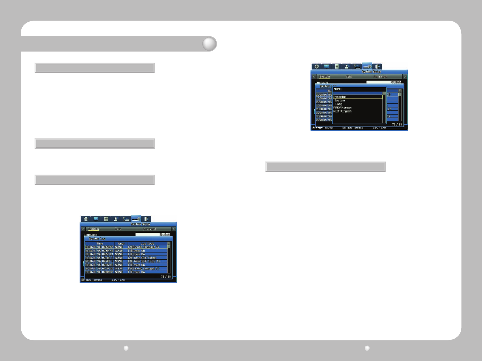
Youcandisplaythesystemlogtoreviewactionsthathaveoccurredortocopythelog.
1. Select System Log from the System submenu on the System tab.
The System Log appears, showing actions that have occurred on the system, such as when
menu settings were changed and when system events occurred.
2.Selectanylinelabeled“CongChanged”toopenasubmenuthatexplainswhatmenusetting
was changed and who changed it.
Figure 6.1.2 System Log submenu of the System Menu
Figure 6.1.3 Config Changed Info submenu from the System Log
Copying the System Log
YoucansaveasystemlogtoaUSBashdrive.
1.InsertadriveintoaUSBport.
2.OpentheSystemLoglist.
3.PresstheCOPYbuttononthefrontpanel.
4.Whentheconrmationmessageappears,selectYestoproceedwithcopyingthelog.
Thesystemlogsissavedasatextle,withthelename<ModelName>_System
Log_<Date&Time.txt>—forexample,SVR1670_SystemLog_20090101_153025.txt
Digital Video Recorder User Guide
50
Digital Video Recorder User Guide
51
Chapter 6. Using the System Setup Menu
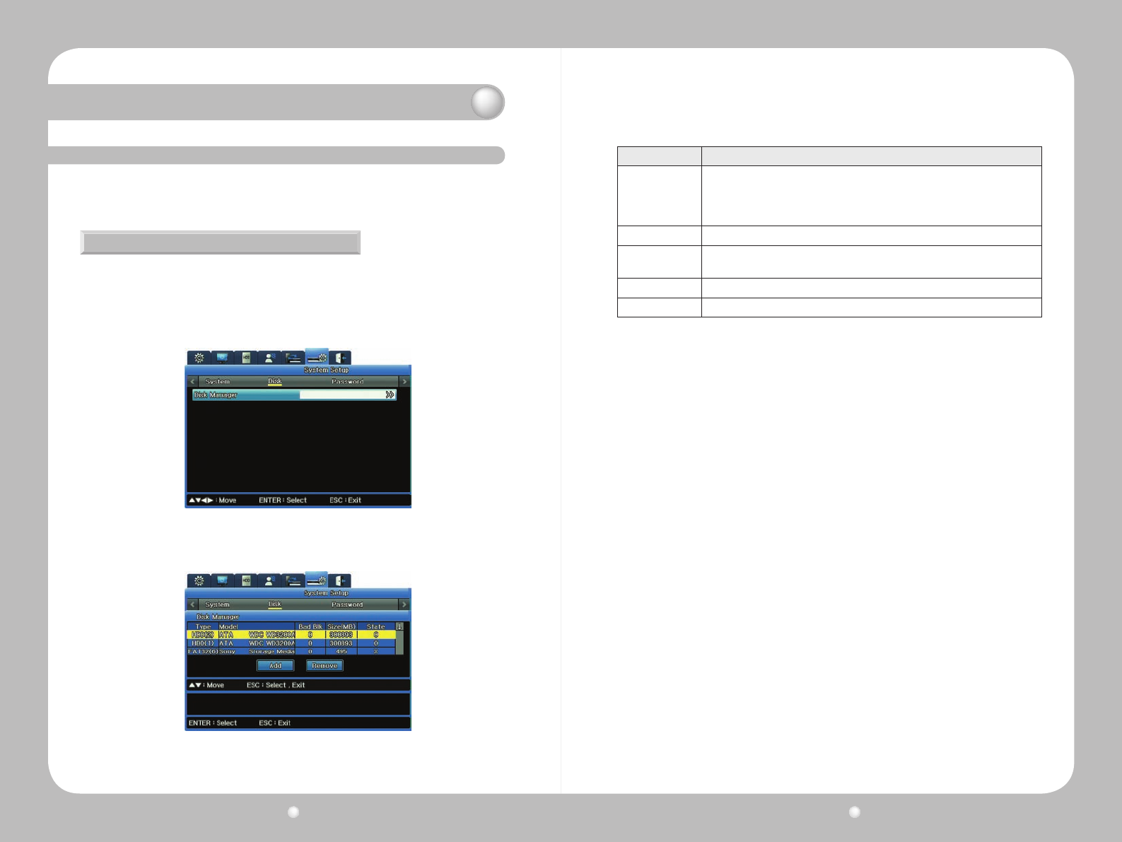
Figure 6.2.1 Disk Submenu of the System Setup Menu
Figure 6.2.2 Disk Manager submenu on the System Setup Menu
ColumnHeading Data
Type
Disk locations and types:
· HDD(1)(Int 1 HDD)
· HDD(2)(Int 2 HDD)
· HDD(3)(Ext 1 HDD)
Model
HDD model numbers
Bad Block Displays HDDs with bad blocks. “O” means no HDDs have problems. Blank means
the HDD is disabled.
Size (MB) Displays HDD sizes in MB.
Enabled “O” means the HDD is enabled. “X” means the HDD is disabled.
To Enable an Inactive HDD
1.InDiskManager’sStatecolumn,select“X”.
2.Select“Add”.
3. The following message appears: “This disk must be formatted before use. Would you like to
format it?”
-Select“Yes”todeleteallthedataintheHDD.
-Select“No”tokeepallthedataintheHDD.
4.TheHDD’sstatuschangesto“O”intheStatecolumn.
To Disable an Active HDD
1.UnderDiskManager’sStatecolumn,select“O”.
2.Select“Remove”.
3. The following message appears: "Would you like to remove the disk?"
-Selecting“Yes”changestheHDDstatusto“X”intheStatecolumn.
-Selecting“No”cancelstheremovalandretainstheHDDstatusas“O”.
The Disk submenu under the System Setup menu tab provides the Disk Manager option to manage
internal and external HDDs.
Working with the Disk Manager Submenu
WiththeDiskManager,youmanageinternalandexternalHDDstotracktheirstatus,badblocks,
size,whetherenabledordisabled.
6. 2 Using the Disk Options on the System Setup Menu
Digital Video Recorder User Guide
52
Digital Video Recorder User Guide
53
Chapter 6. Using the System Setup Menu
6. 3 Working with Passwords and Permissions
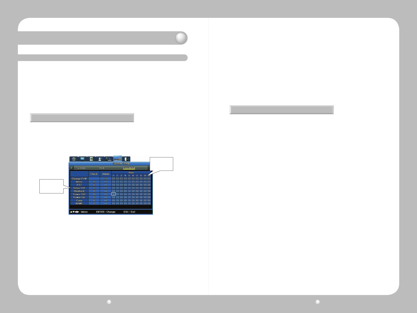
You set up permissions on the System Setup Menu’s Password submenu.
Permissions are granted, or withheld, for using the various features and performing various tasks.
•TheadministratorhasallpermissionstouseallfunctionsoftheSVR-1670.
•General users must be granted permissions to use features.You can set permissions for a
maximumof10 users.Eachuser canhavecompletelydifferent permissionsthananyother
user—orallcanhaveidenticalpermissions.
Setting and Reviewing Permissions
OnthePasswordsubmenu,thereareseveralcolumns:
The far left column shows various features for which permissions must be granted (such as
permissiontousePTZ,permissiontoturnoffpower,permissiontocopyvideo).
Figure 6.3.1 Password submenu on the System Setup Menu
Users listed by
number, 1-10
Tasks for which
permission must
be granted
ThecolumnsnexttoAdminareforUsers.
·An“O”onanyrowinthiscolumnmeansallusershavepermissiontousethatfeature.
·An“X”onanyrowinthiscolumnmeanseachusermusthavespecicpermissiontousethat
feature.
·Inthegure:6.3.1PasswordsubmenuontheSystemSetupMenu,User1haspermissionsfor
Menu,Playback,andPowerOff.User2haspermissionsforPTZ,RelayOff,Playback,PowerOff,
PowerOn,andCopy.
ThenextcolumnisCheck.
·An“X”onanyrowinthiscolumnmeansallusershavepermissiontousethatfeature.
·An“O”onanyrowinthiscolumnmeanseachusermusthavespecicpermissiontousethat
feature.
ThecolumnnexttoCheckisAdmin.
·TheAdministratoralwayshaspermissiontoperformalltasks.ThiscolumncontainsOs,and
cannotbemodied.
Knowing Your Password
WhenyourstcongureyourSVR-1670,thedefaultpasswordsare:
·ForAdmin,11111111.
·Forusers,the8-digitpasswordsfollowthispattern:User1is111111111;User2is22222222,
andsoon.ForUser10thepasswordiseight0sinarow.
Youcanchangepasswordsifyouhavepermissiontodoso.
Digital Video Recorder User Guide
54
Digital Video Recorder User Guide
55
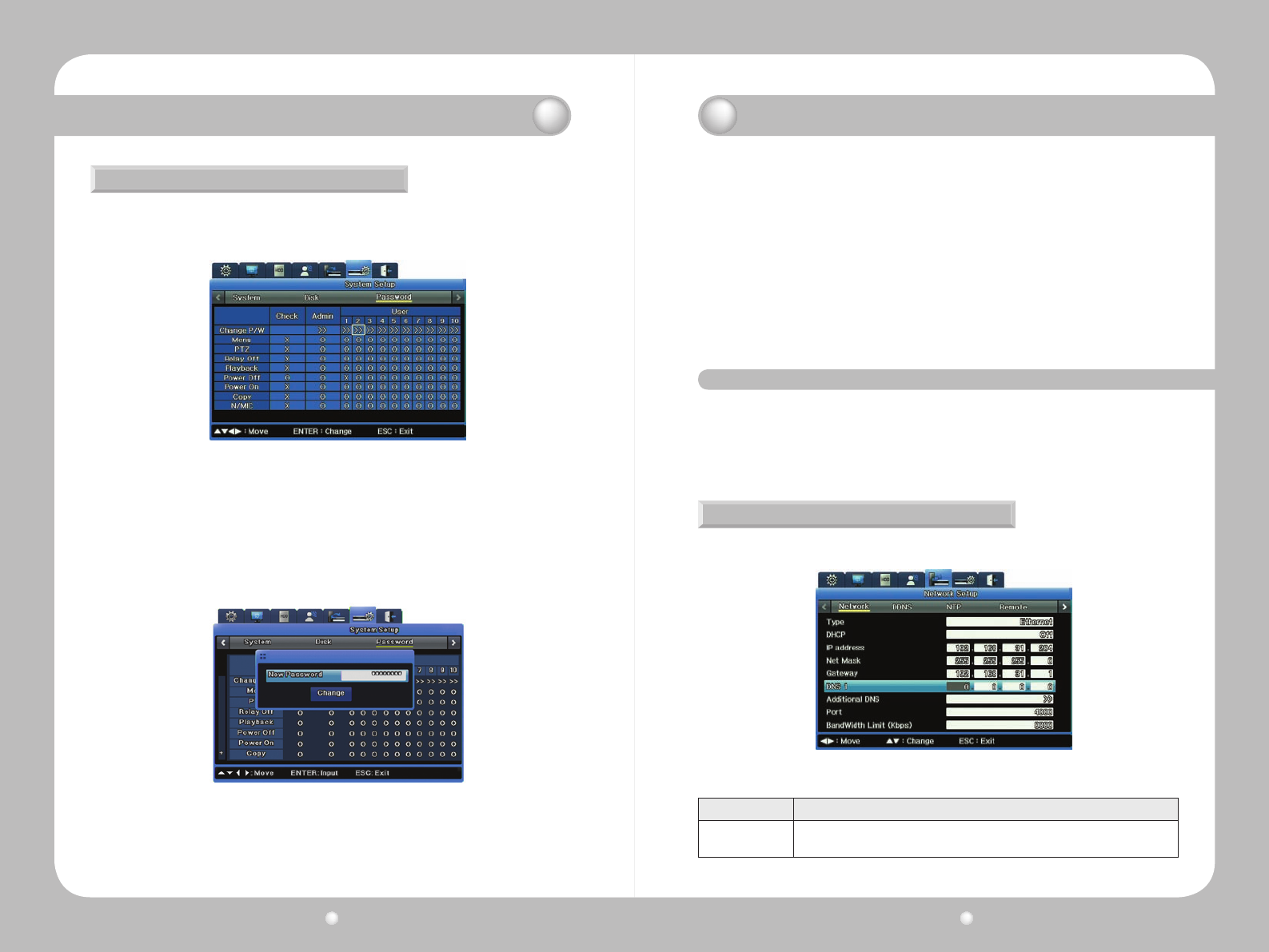
Changing Passwords
If you have the correct permission, you can change user passwords.
1.IntheChangeP/Wrow,selecttheuserwhosepasswordyouwanttochange.
2.ANewPasswordsubmenuopens,inwhichyouenterthenewpassword.
·EnterthenewpasswordusingeitherthenumberbuttonsontheSVR-1670’sfrontpanelor
theon-screenkeyboard.
·Passwordsmustbean8-digitnumberbutcanbeanynumbersinanysequence
3.ClicktheChangebutton.
Chapter 6. Using the System Setup Menu
Figure 6.3.2 Changing a Password
Figure 6.3.3 New Password submenu
Figure 7.1.1 Network Submenu for the Type Ethernet (on the Communication Menu)
Chapter 7. Communication To/From the DVR
TheCommunicationmenuoptionsallowyoutocongureforcommunicationtoandthrougha
network,aDDNSserver,NTPsynchronization,andremotecontroldevices.
These topics are explained in the following sections :
▶7.1SettingupNetworkCommunication
▶7.2RegisteringwithaDDNS.
▶7.3SettingupforNTPSynchronization
▶7.4SeeSettingupRemoteControl
▶7.5SeeSettingupStreaming
▶7.6SeeSettingupIPFilter
7.1. Setting up Network Communication
Before you enter settings on the Network submenu, you need to know the type of network connected
to the DVR. The type is either :
• Ethernet, if the DVR is connected to dedicated line, cable modem or LAN.
• xDSL, if the DVR is connected to a PPPoE-type xDSL line.
Setting Up for Ethernet
ThissectiondiscussestheoptionsavailableifyourNetworkTypeisEthernet.
Option Setting
Type
Ethernet is the correct type if the DVR is connected to dedicated line, cable modem
or LAN.
Digital Video Recorder User Guide
56
Digital Video Recorder User Guide
57
DHCP
Dynamic Host Configuration Protocol (DHCP) manages host addresses on a
network. DHCP is used on a LAN with a DHCP server installed. If the LAN has a
DHCP server and you have enabled this DHCP option, the DHCP server will allocate
an IP address to the DVR.
IP Addr
IP Address is used for communication between the DVR and SVM-S1, and is also
used when Web Viewer accesses the DVR. It is available only when Net Mask and
Gateway are set.
Net Mask Net Mask specifies a range of IP addresses and enables IP addresses in the range
to communicate. Net Mask should be allocated by a network administrator.
Gateway Gateway must be specified to enable IP addresses to communicate and should be
allocated by a network administrator.
DNS1 DNS1 must be specified to register the DVR to DDNS Server(www.samsungipolis.
com) while DNS Address should be allocated by a network administrator.
Additional DNS Additional DNS is used to replace DNS1 when it is unstable or has a problem.
Port Port is used to register to SWR, connect to SVM-S1, or connect to Web viewer. The
default port is 4000.
Bandwidth Limit
(Kbps)
Kbps sets the maximum transmission speed of data output from the DVR (the
data transmission capability of the DVR). This can be left blank. Ask your network
administrator to specify it when necessary.
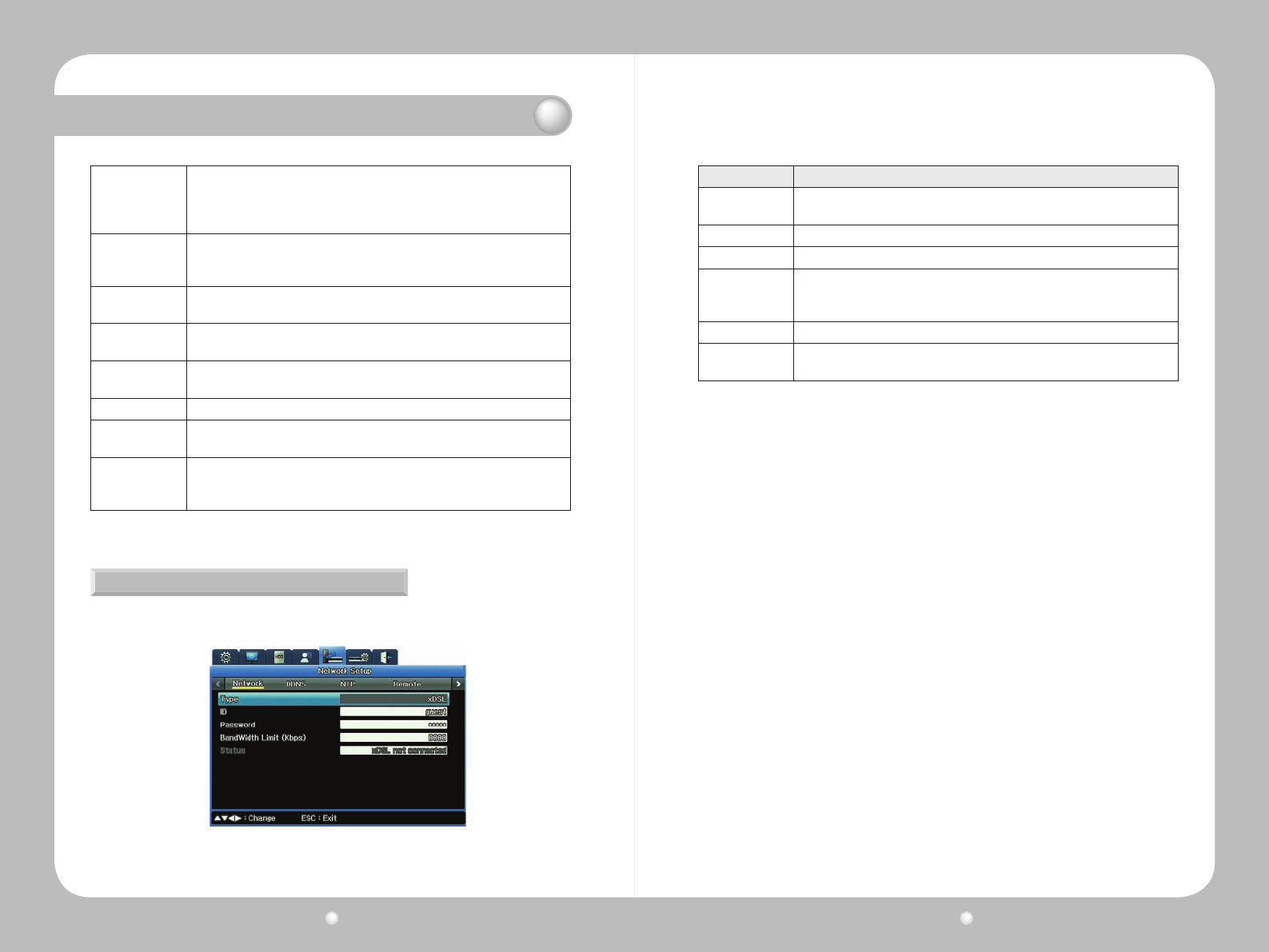
Setting up for xDSL
ThissectiondiscussestheoptionsavailableifyourNetworkTypeisxDSL.
Figure 7.1.2 Network Submenu for the Type xDSL (on the Communication Menu)
Option Setting
Type xDSL is the correct setting if the DVR is connected to a PPPoE-type xDSL line.
(If the xDSL line is not of the PPPoE type, you must select Ethernet.)
User ID Enter your User ID.
Password Enter your password.
Bandwidth Limit
(Kbps)
This sets the maximum transmission speed of data output from the DVR (the
data transmission capability of the DVR). This can be left blank. Ask your network
administrator to specify it when necessary.
Status
Displays the connection status of the DVR.
Port Port is used to register to connect to SVM-S1 or to Web Viewer. The default port is
4000.
Chapter 7. Communication To/From the DVR
Digital Video Recorder User Guide
58
Digital Video Recorder User Guide
59
7. 2. Registering with a DDNS Server
To make the DVR’s IP address easily identiable, your can register, with a DDNS server, a dynamic IP
address for the DVR. (Otherwise, the DVR has as a different IP address assigned every time it connects
to the ISP, making it difcult to determine the DVR's IP address.)
This section explains how you complete DDNS setup, by:
•RegisteringaDVRwithaDynamicIPAddress
•ConguringtheDVRforDDNS
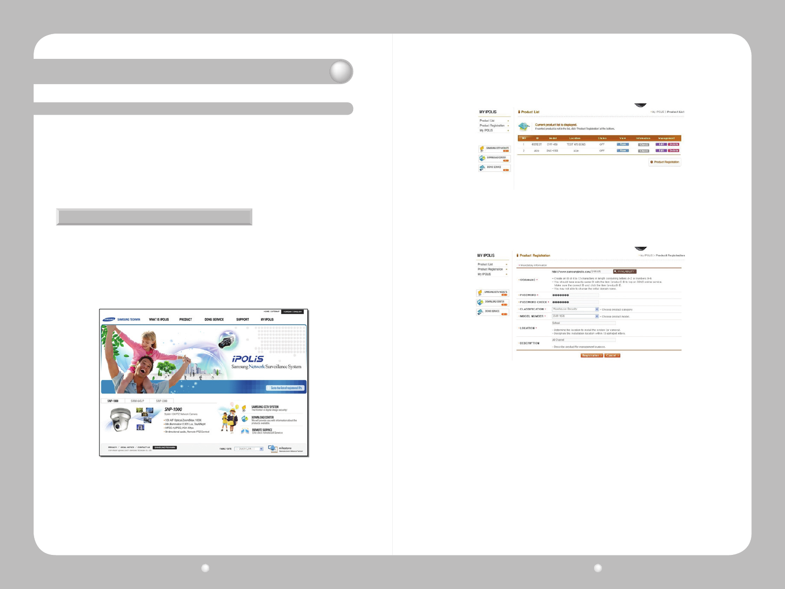
Registering a DVR with a Dynamic IP Address
1.GototheiPOLiShomepage,www.samsungipolis.com,andlogin.
·Ifyoudonothaveanaccount,gototheMyiPOLiSpage,clickSignUpandfollowtheprompts
to set up an account.
※NOTE:TheiPOLiSwebsiteisoptimizedforuseonlywiththeMSInternetExplorerbrowser.
Figure 7.2.1 iPOLiS Home Page
3.ClicktheProductRegistrationlinktoopenthescreenonwhichyoucanregisteryourDVR.
4.OntheProductRegistrationpageenter:
·IDforyourproduct.Thiswillbecomeitsdomainname.OnceyouregisterthisID,itcannotbe
changed.
·YouriPOLiSpassword.
·ChooseaClassicationforyouruseoftheDVR.
·ChoosethemodelnumberoftheDVR.
·Enteralocation.Thiscanbeanysortofword,phraseorcodethatmakessensetoyour
business and situation.
·Enteradescription.This,too,canbeanysortofword,phraseorcodethatmakessenseto
your business and situation.
·ClicktheRegistrationbutton.
Figure 7.2.2 Product List on My iPOLiS Page
Figure 7.2.3 iPOLiS Product Registration Page
Chapter 7. Communication To/From the DVR
Digital Video Recorder User Guide
60
Digital Video Recorder User Guide
61
Chapter 7. Communication To/From the DVR
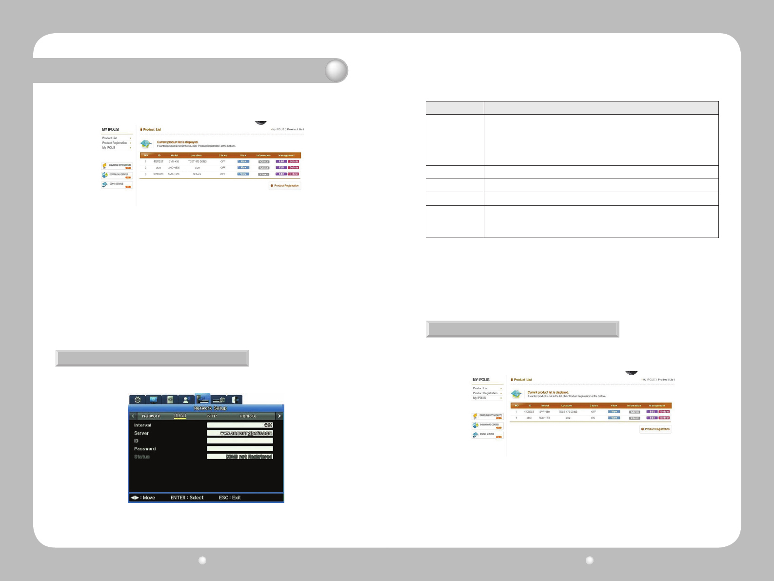
5.ThenewlyregisteredDVRnowappearsonyourProductListpage:
Figure 7.2.4 iPOLiS Product List Page
TomanagetheregisteredDVR
FromtheProductListyoucan,byclickingtheappropriatebutton,View,CheckorEditthe
registration information about any particular product.
·Youcaneditdataabouttheproduct,butyoucannotedititsID.IfyouwanttochangeitsID,
delete it and register it again, using a new ID.
·ClickDeleteifyouwanttoremovetheDVRfromyourlist,eitherpermanentlyortore-registerit
with a different ID.
NowthatyouhaveregisteredtheDVR,youneedtocongureitforDDNS.
Conguring the DVR for DDNS
CompletethedynamicIPaddresssettingsfortheSVR-1670followingtheinstructions,andthen
conguretheDDNSsettings.
Figure 7.2.5 DDNS Submenu on the Communication Menu
Option Setting
Interval
The dynamic IP address renews the relevant data from the DDNS per each interval,
thus maintaining a continuous registration status.
If you set the registration interval to Off or if the DVR does not upload any
information over two days, information for the DVR will be removed from the DDNS
server.
Server Enter your DDNS server address. The default is www.samsungipolis. com.
ID Your iPOLiS sign in ID.
Password Your iPOLiS password.
Status
DVR's registration status.
∙ Not Registered means that the DVR is not registered to the DDNS.
∙ Date/Time & OK means that the DVR has been registered to the DDNS.
Verifying the Connection Status
LogintoiPOLiSandreviewtheProductlist,toverifythattheProductListshowstheDVR’sstatus
as'On'.
Figure 7.2.6 iPOLiS Product List Showing “On” Status
Digital Video Recorder User Guide
62
Digital Video Recorder User Guide
63
Chapter 7. Communication To/From the DVR
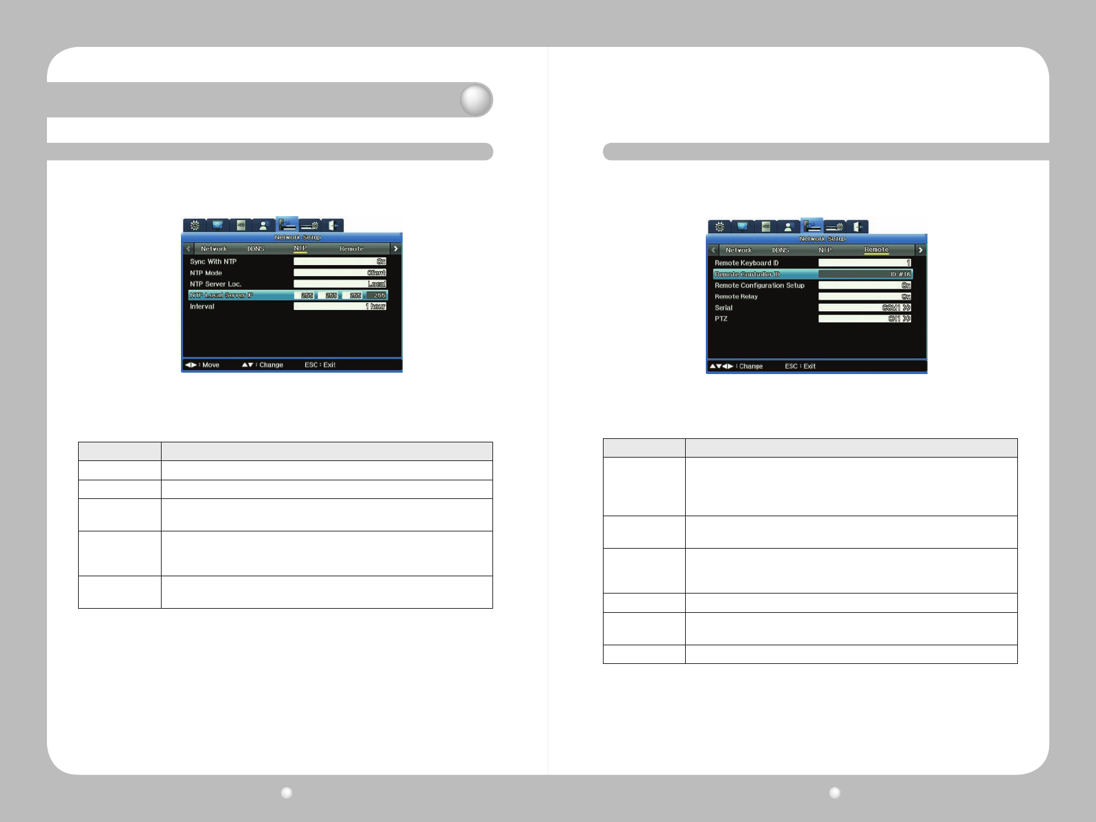
7. 3. Setting up for NTP Synchronization
Network Time Protocol (NTP) synchronizes time between devices on network. On a network, a server
provides the base time. The client systems receive the time from that server for synchronization.
Set the options to your preferred settings to congure NTP :
Figure 7.3.1 NTP submenu on the Communication Menu
Option Setting
Sync With NTP Turns NTP on or off.
NYP Mode Sets NTP Mode to Client, Server or All.
NTP Server
Location
Determines whether the NTP server is on a local network or on the Internet. This
option is only available if NTP Mode is set to Client.
NTP Local Server
IP
Sets the IP of the NTP server. Enter either the IP of an NTP server on the local
network or the IP of a DVR with its NTP mode set to Server.
This option is only available if the NTP Server Location is set to Local.
Interval Set the synchronization interval; how often you want your system to communicate
with the server to synchronize the devices.
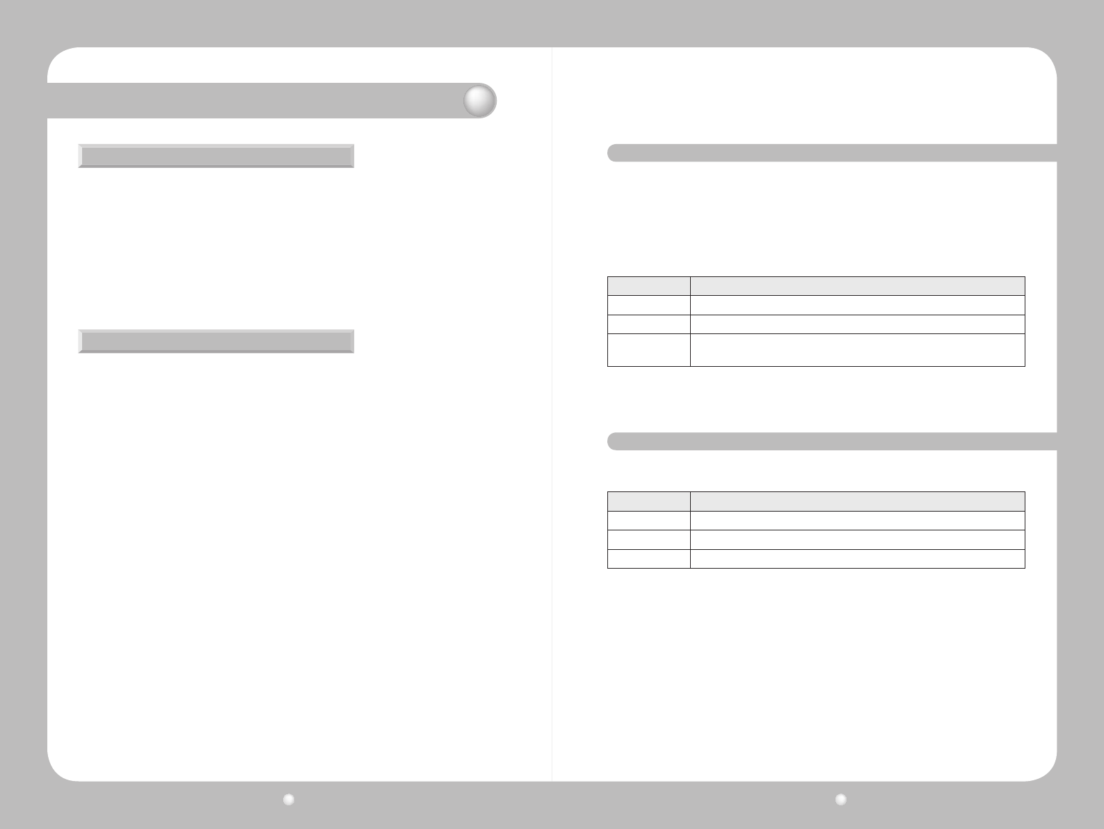
Option Setting
Remote Keyboard
ID
Designation the keyboard operating all DVR functions with the controller buttons.
The default value is 1.
NOTE: If one keyboard is connected to several DVRs, it might conflict with other
channels, so a different value should be set for the keyboard address.
Remote Controller
ID
You can control up to 16 DVRs from one remote control by creating unique IDs for
each DVR.
Remote
Configuration
Setup
Enable or Disable configuration to system management software.
Remote Relay Enables relays to be operated from the system management software.
Serial Port Four serial ports are available for the DVR; two RS-232C ports and two RS-485
ports.
PTZ Setting up PTZ options.
You can operate the DVR with various remote control devices.
Figure 7.4.1 Remote Control submenu on the Communication Menu
7. 4. Setting up Remote Control Devices
Digital Video Recorder User Guide
64
Digital Video Recorder User Guide
65
Chapter 7. Communication To/From the DVR
Setting Serial Ports
Setting PTZ Options
Tosettheserialport,rstselecttheCOM(communicationport):
∙COM1andCOM3arexedtoRS-232C
∙COM2usesRS-422/RS485
∙COM4usesRS-485.
1.AccesstheSerialsubmenu(totherightoftheCOMselection).
2. For the Devise option, select a connected device.
3.Settheotherselections—Baudrate,theParity,StopBitandDataBit—asappropriateforthe
deviceyou’vechosen.
TosetPTZoptionsforyourcameras,rstspecifythecamera’schannel,1through16.
1.AccessthePTZsubmenu(totherightofthePTZchannelselection).
2.SetPTZHometoOnifyouwantthecameratoreturntohomeifPTZisnotcontrolledfora
speciedperiodoftime.Otherwise,settoOff.
3.IfPTZHomeissettoOn,setthePTZIdleTime.Thisisthedurationoftimebeforewhichthe
camerareturnstohome.Forexample,ifyousetthisto5seconds,PTZreturnstoHomewhen
PTZisnotcontrolledformorethan5seconds.
4.SetthePTZPortbyselectingtheporttowhichthecamerachannelisconnected.
5.SelecttheCameraIDoftheconnectedPTZcamera.
You can set up the SVR-1670 for streaming data. This section describes how to set up streaming
options.
• RTSP/TCP : Convenient to use in conjunction with a simple rewall that allows RTSP transmission.
• RTP/UDP : Effective when the latest video data from a camera must be transferred, even if it causes
video loss.
• RTSP Standard Port (554) : Select to use the RTSP standard port (554).
You can selectively block or allow IPs to access the SVR-1670.
7. 5 Setting Up Streaming Options
7. 6 Setting Up IP Filters
Option Setting
RTSP/TCP Select to use RTSP/TCP.
RTP/UDP Select to use RTP/UDP.
RTSP Standard
Port(554) Select to use the RTSP standard port.
Option Setting
Use Select to use the IP filter.
Default Policy Select to block or allow IPs using the default policy.
IP Range Select a range of IPs to block or allow; Check the checkbox, and then enter the IPs.
Digital Video Recorder User Guide
66
Digital Video Recorder User Guide
67
Chapter 8. Working with Events
ThischapterprovidesinformationaboutactionsyoucantakeontheEventSetupmenuofthe
OSD.
The information is presented in these sections:
▶8.1AboutEvents
▶8.2SettingUpforEventRecording
▶8.3WorkingwithNormalEvents
▶8.4WorkingwithPresets
▶8.5WorkingwithDigitalI/O
8. 1 About Events
8. 2 Setting Up for Event Recording
With Event setup, you prepare the DVR to record when an event occurs. Event recording is launched
based on input sensor, by motion detection, by text and by digital input. An event can be various
things :
•
Loss of video feed
•
Motiondetectedinamonitoredarea
•
The disk being full and no longer able to record
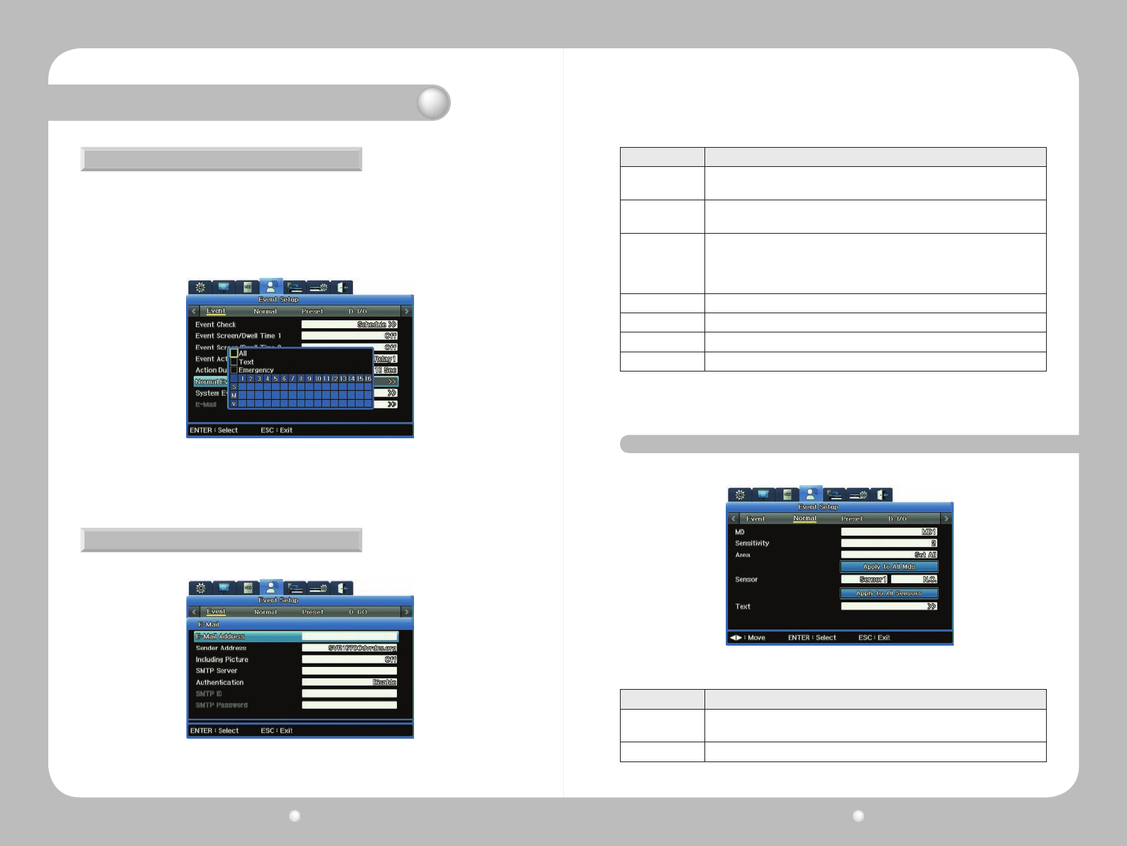
You set up for event recording from the Event submenu of the Event Setup menu on the OSD.
For each option, enter the appropriate setting :
Event Recording can be set up in conjunction with other recording modes: i.e. Manual & Event or
Schedule & Event.
Figure 8.2.1 Event Submenu on the Event Setup Menu
Option Setting
Event Check
Three options are available to check events. To detect events at all times, select
“Always.” To disable event detection, select “Off.” To detect events only for a preset
duration, select “Schedule”.
Event Screen/
Dwell Time Select the Monitor for which you are setting the dwell time.
Event Action Select what action should notify you about the Event: Relay 1~4, buzzer, or E-Mail.
Action duration How long the Event Action should last, for the relay or buzzer. (E-mails are sent in
specified time intervals.)
Normal Event
Source
What action will trigger the event. Check the appropriate box for Sensor, Motion
detection area, Camera channels (for video loss) or Text.
System Event
Source
Press PLAY/ENTER to select and define an instance as the system event: Disk Error,
Disk Full, Fan Error, Authentication Failed, or DDNS Registration Failed.
E-Mail Setup This option become available if you selected Email as the Event Action. See
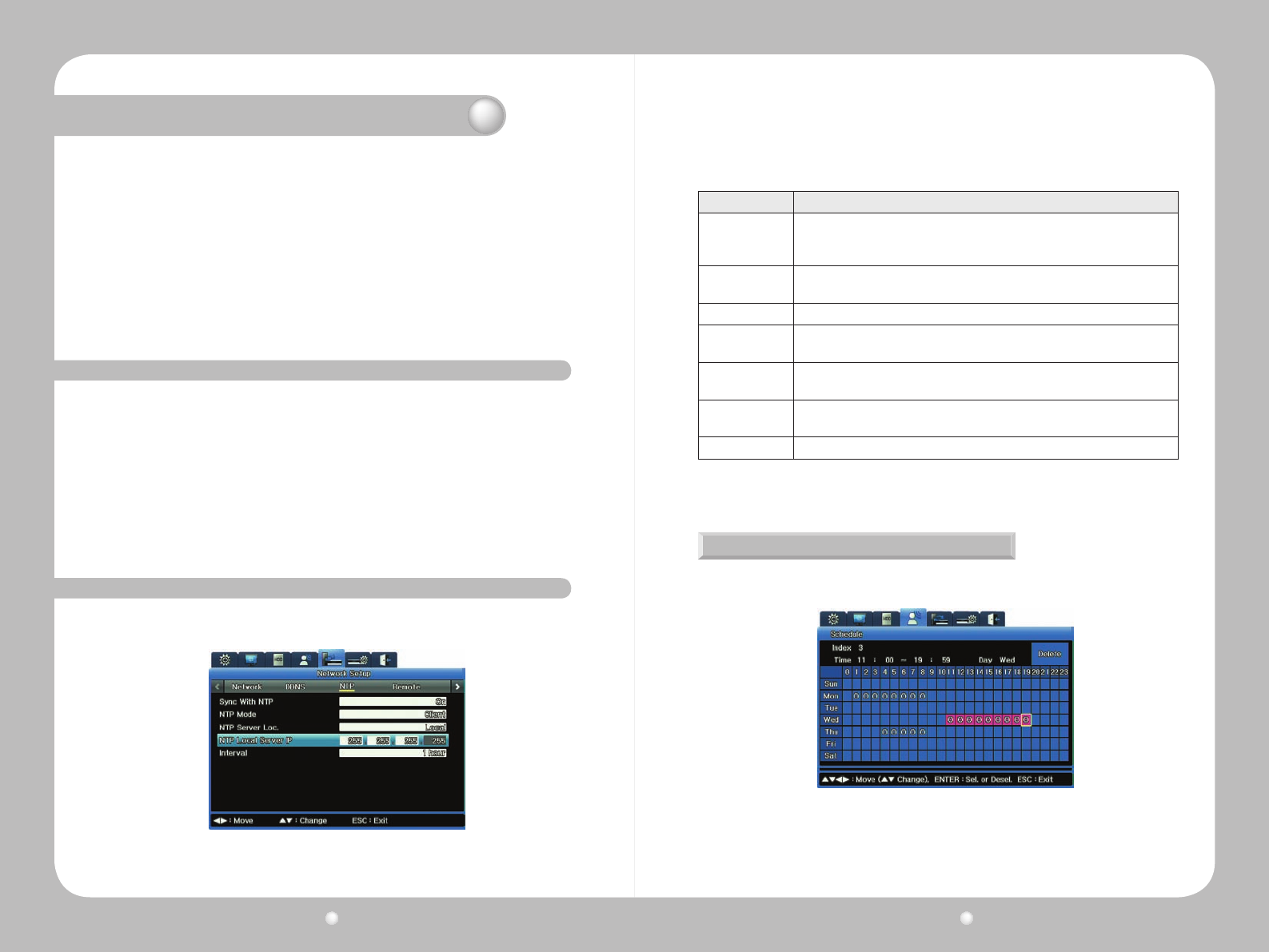
Working on the Schedule Submenu
Youcanscheduleeventsforspecichours.Youcansetwhateverworksforyoursurveillance
situation by day of week and hours of day.
Figure 8.2.2 Schedule submenu on Event setup
Digital Video Recorder User Guide
68
Digital Video Recorder User Guide
69
Chapter 8. Working with Events
Working with the Normal Event Source Submenu
Setting Up E-Mail for Event Action
Thenormaleventsourceistheactionthattriggerstheevent.Youaccessthissubmenufromthe
EventsubmenuontheOSD’sEventSetup.
S stands for sensor.
MstandsforMotionDetection.
V stands for Video.
IfyouselectedEmailastheEventActionoption,yousetitupontheEmailSetupsubmenu.
ChecktheappropriateboxesforSensor,Motiondetectionarea,Camerachannels(forvideoloss)
orText.Youcancheckasmanyboxesasyouneed.
Figure 8.2.3 Normal Event Source submenu on the Event Submenu
Figure 8.2.4 Email Setup submenu
Option Setting
Email Address Enter the e-mail address of the person receiving the notification. Use only Roman
alphabet letters and numbers, in the format is xxxx@xxxxxx.xxx.
Sender Address Enter an email address that identifies the DVR as the sender of the notification.
This field is optional: If you use it, the format is xxxx@xxxxxx.xxx.
Including Pictures
For a Normal event, the system sends an e-mail with an image of the event
channel as well as event information including the sensor, movement detection,
and object disappearance.
For a System event, the system sends only event information.
Server Enter an SMTP server to send email.
Authentication Select a server, and then set to Use.
ID If Authentication is set to Use, enter your ID for the SMTP server.
Password If Authentication is set to Use, enter the password for the ID entered above.
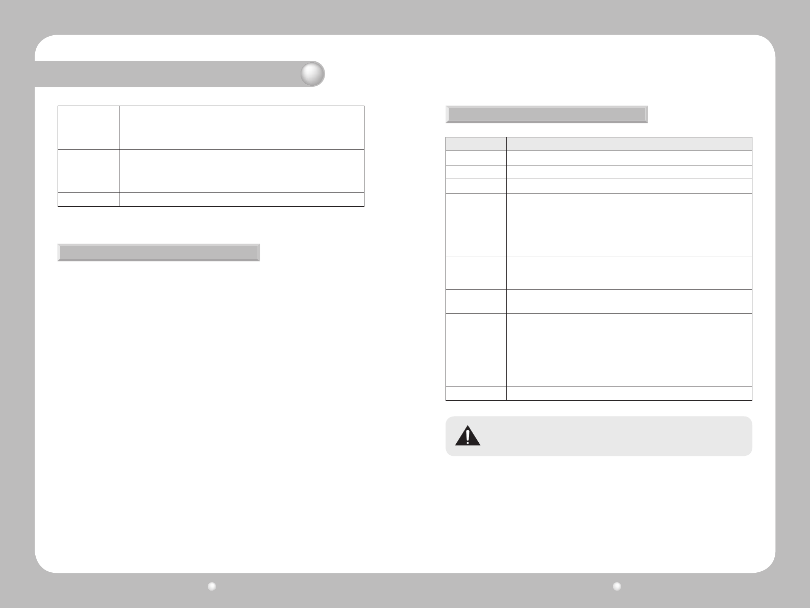
Option Setting
MD
(Motion Detection)
Enables each channel or all channels to detect motion and notify users. Select one
specific channel or set to All.
Sensitivity Set to Lowest, 1~10, Highest or Off.
Figure 8.3.1Normal Event submenu on the Event Setup Menu
8. 3 Working with Normal Events
Digital Video Recorder User Guide
70
Digital Video Recorder User Guide
71
Chapter 8. Working with Events
Area
If the MD Channel is set to All, the motion detection areas can be set to Set All or
Clear All.
If an individual channel is set for MD, Area can be set to Set All, Clear All or Select
Area.
Sensor
You can set one sensor for the channel selected, of you can select all sensors (of
16 possible sensors available).
Select the sensor, and set it to either N.O. (Not Open) or N.C. (Not Closed), or the
setting can be Off.
Text For text settings.
Setting the Area for Motion Detection
Setting for Text Events
Youcansetaparticularareaformotiondetectionsurveillance.
Forexample,ifyourcamerapointstothecardealership’scarlot,youwillprefermotiondetection
aroundthecarsthemselves.Youwillbelessinterestedinmotiondetectiononthetreesorlight
polesthatsurroundyourlot.Inthiscase,youcanlimittheMotionDetection(MD)zonearound
the cars. To set your motion detection area:
1.FromtheNormalEventsubmenu,intheAreaoption,setSelectArea.
2.FortheCustomAreaoption,accesstheCustomAreagrid,whichshows330squaresina
22x15representingtheareayourcamera“sees.”
3.Clickasquaretosetitwithinyourmotiondetectionarea.Youcanbuildupaslargeadetection
area as you wish, positioned in whatever area of the grid is appropriate.
·Eachsquareturnsgraywhenclickedandpartofthedetectionarea.
·Clickanysquaretodeselectit.
Option Setting
Recording You can turn recording for text input on or off.
Sync Text With This selects channels to link with text data.
Device Select from various third-party devices, or select Manual.
Seek Header
By defining a header here, the DVR can recognize from the header that it is the
start point of the data. Two headers can be set and detected because one device
can send various types of data to external receivers.
However, this parameter is needed to see how one unit of data out of continuously
incoming text data is structured. All data has its start and end points, and the
header is data that is always inserted to indicate the start point.
Header 1
and
Header 1
Use the onscreen keyboard to enter the text you want displayed for the headers.
Delimiter The delimiter value will differ depending on the device used. For more information
on delimiters, refer to the user manual or the device manufacturer.
Timeout (ms)
DelimiterLines defined below are the maximum number of text lines available
for one piece of data. Even though data is standardized, lengths might differ.
For example, three lines are programmed for client name input for an ATM, but
if someone registers only his/her first name and last name, only two lines are
provided when the person uses an ATM. However, the DVR cannot detect this
automatically, so Timeout is used to determine how long is needed to recognize the
received data as complete data after the last line is entered.
Lines Define the maximum number of lines for one piece of data.
External devices might not be recognized depending upon their particular features. Review
their product documentation or contact their manufacturer for information.
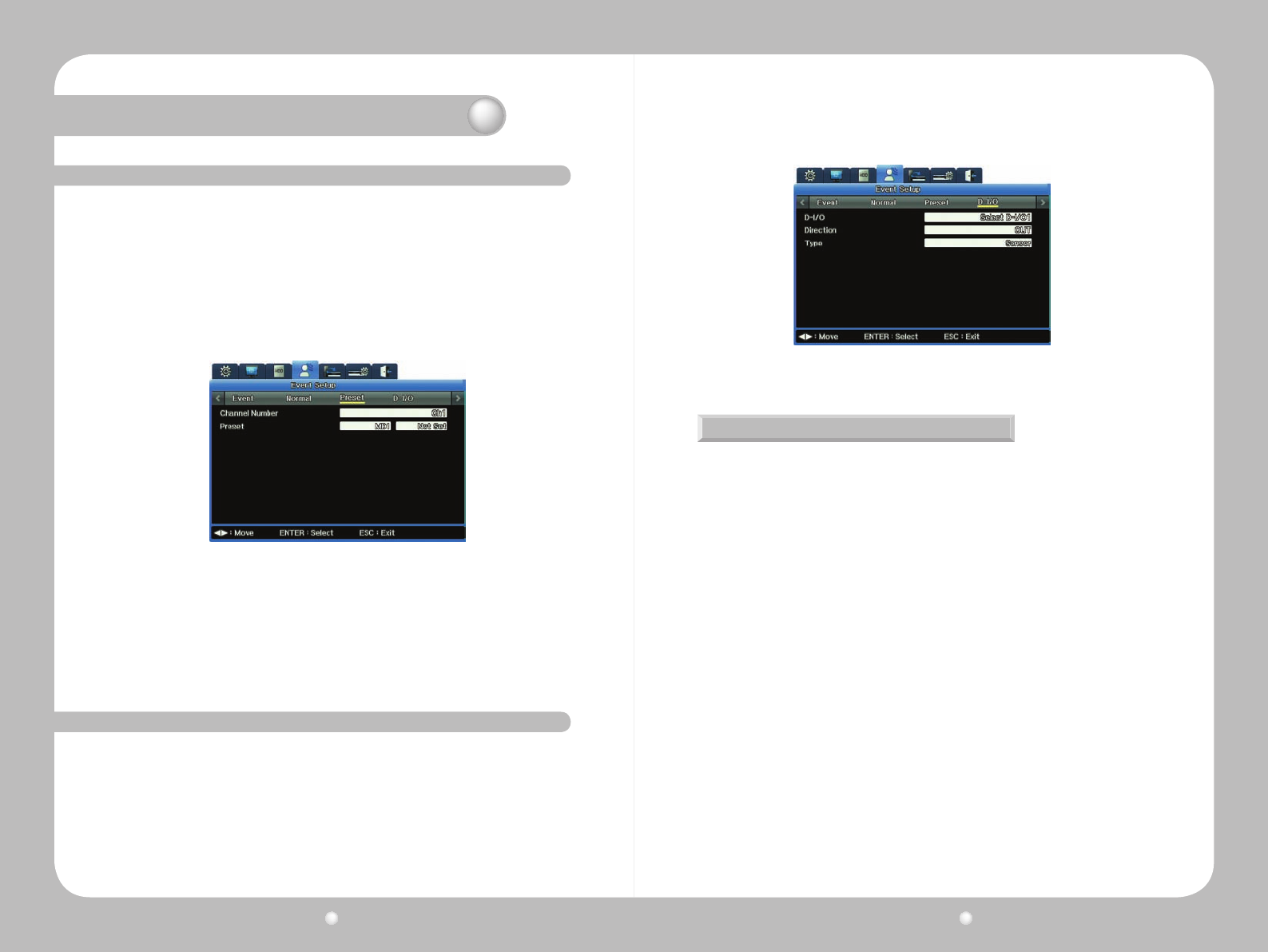
Digital Video Recorder User Guide
72
Digital Video Recorder User Guide
73
Chapter 8. Working with Events
On the Preset submenu, you can setup for event detection based on preset camera angles you specify
in the PTZ menu.
First, you need to dene the preset for the PTZ camera attached to the channel.
1.OnthePresetsubmenuoftheEventSetupmenu,
-Setachannelnumber.
-Choosethetypeofevent—sensor,text,orMD(motiondetection).
-EnterthePresetnumber.
Figure 8.4.1 Preset submenu on the Event Setup Menu
Figure 8.5.1 The Digital I/O submenu of the Event Setup Menu
8. 4 Working with Presets
8. 5 Working with Digital I/O
Digital I/O are digital ports available for input and output at the same time. The SVR-1680/1660 has 12
digital inputs and outputs, all of which can be set to either input or output:
-Whensettoinput,ifsensorinputisreceivedbyevenonechannel,emergencyrecordingwill
operate.
-Whensettooutput,ifsensorinputisreceived—forText,VideoLoss,MotionDetection,Sensor,
orEmergency—itwilloperate.
Emergency Recording
EmergencyRecordingoperateswhenyou:
∙SetoneoftheDlI/OchannelstoInput
∙SetitsInputTypetoEmergency
∙TurnDigitalI/Oto“on”.
RecordingwillbeginandcontinuebasedonthesettingforRecordingAfterEvent.
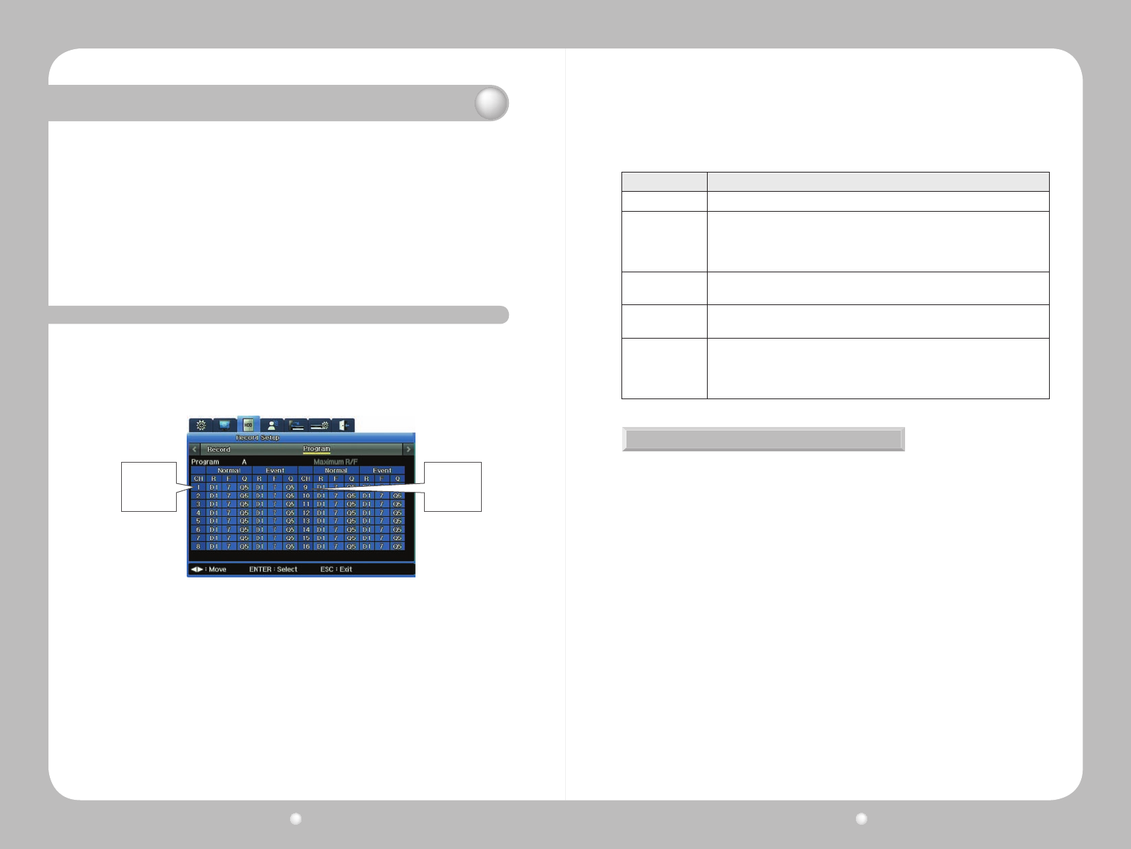
Digital Video Recorder User Guide
74
Digital Video Recorder User Guide
75
This chapter provides information about :
• Scheduled Recording, which records video automatically at a scheduled time
• Manual Recording, which records video manually by pressing the REC button
• Event Recording records video automatically when events occur.
The chapter also discussing conguration settings including programming schedules, advanced
camera and audio setup. The information is presented in these sections :
▶8.1DeningPrograms
▶8.2SettingUpToRecord
8. 6 Defining Programs
Chapter 8. Scheduling and Recording Video
You can dene 26 programs—lableled from A to Z—and specify particular frame rates, video quality
and resolution for each. You then use these programs for both Manual and Schedule recording.
To set up a program :
1.AccesstheProgramsubmenu,ontheRecordSetupmenuoftheOSD.
2.ForProgramoption,selectanyletterfromA-Z.
-Thesettingsforthatprogramdisplay.Foreachpre-setProgram,thesettingsforallchannels
areidentical.YoucaneditanysettingwithinanyProgram.
-Eachchannelhastworecordingmodes:NormalandEvent.Normalrecordingproceedsuntil
aneventoccurs.Whenaneventoccurs,therecordingshiftsintotheEventRecordingsettings
youhavespecied.
-ForbothNormalandEventrecording,therearethreesettings:Resolution,FramesperSecond
andQuality.Allarefurtherexplainedinthetablebelow.
3.Noticethatyoucanhighlightanysettingonanychannel(thebackgroundturnsred)andthen
adjustthesetting.
This table describes the settings :
Figure 8.6.1 Program submenu on the Record Setup Menu
Channels 1-8
are listed on
the left grid.
Channels 9-16
are listed on
the right grid.
Option Description
Ch (Channel) The channel number
R (Resolution)
The recording resolution. Three resolutions are available:
∙ D1 (704 x 480)
∙ Half D1 (704 x 240)
∙ CIF (352 x 240)
F (fps) Frames per second, from 1 to 30fps
The maximum frame rate varies depending on settings.
Q (Quality) The recording quality: Q5, Q4, Q3, Q2, and Q1.
For Event Recording, Q3 or higher is recommended.
Maximum R/F
This box displays the maximum frame rate available for the selected resolution. For
example, if CIF 30fps appears in this box, it means that you can select up to 30fps
for the CIF resolution of a selected channel. D1 30fps means that you can select
up to 30fps for the D1 resolution.
About Recording Performance & Capacity
RecordingperformancefortheSVR-1680/1660isCIF480fpsforbothNormalandEvent
Recording.
∙Whenbothrecordingmodesareineffect,recordingperformancemustnotexceedCIF480fps.
Theresolutionandmaximumframeratevarydependingonthenumberofenabledchannels.
∙D1(704x480)=2xHalfD1(704x240)=4xCIF(352x240)
∙120D1compressedframes=240HalfD1compressedframes=480CIFcompressedframes.
Event Settings Limitations
WheneverychannelissetuptorecordNormallyatCIF30fps,theEventsettingsfortherst
channelarelimitedtoCIF30fps,Half15fps,andD17fps.
IfyouwanttosettheEventsettingstoD130fps,theNormalsettingsoftheotherchannelsmust
bechangedtototalCIF360fpsorless.
Freeing Up Capacity
Youcanfreeupcapacitybydisablingunusedchannels.Ifachannelisdisabled,itssurplusCIF
30fps becomes available for other use.
∙Todisableachannel,gototheDisplaySetupmenuontheOSD:SelecttheChannelNumber,
thenfortheStatusoptionselectDisable.Ifdisabled,thechannelisgrayed-outontheProgram
menu and is uneditable.
Settingachannel’sresolutionto0fpsdoesnotfreeupspacebecausethechannelstill
uses2-3recordingframespersecond—evenwhensetto0fps—fortaskssuchasnetwork
communications.
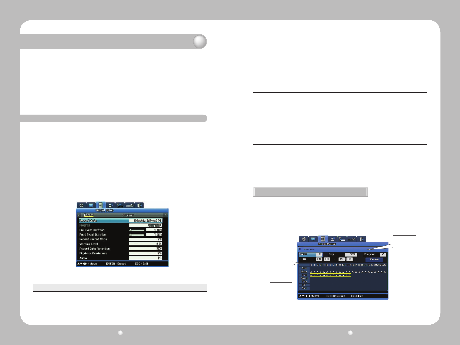
Digital Video Recorder User Guide
76
Digital Video Recorder User Guide
77
When Events Occur in Multiple Channels Simultaneously
IfeventsoccursimultaneouslyinmultiplechannelsandtheEventsettingsexceedstheDVR's
maximumrecordingperformance:
∙theNormalsettingsvalueisretainedand
∙thechannelswitheventsdroptheirEventframeratessettingstorecordtheevents.
However,theSVR-1670providesD130compressedframesforallchannels;itcanrecord
programs at a manually selected resolution and frame rate at all times.
Chapter 8. Scheduling and Recording Video
8. 7 Setting Up To Record
You set up recording—either Manual or Schedule—from the Record Setup tab of the OSD.
Recording allows you to choose a program to record. The resolution, frame rate, and quality will vary
depending on program you select.
Manual Recording
ManualRecordingbecomesactivatedwhentherecordingmodeissettoManual&Event.Selecta
programandpresstheRECbuttontobeginrecording.
Schedule Recording Settings
Schedule Recording records video automatically at a scheduled time according to the chosen
program settings. Set the recording mode to Schedule & Event then select a program for a
scheduled date and time.
Figure 8.7.1 Record Submenu “Schedule & Event” Record Mode Setting
Option Description
Record Mode
Schedule & Event
or
Manual & Event.
Schedule
Or
Program
If your record mode is Schedule & Event, you set your Schedule option here. If you
record mode is Manual & Event, you select your Program here.
Event Duration Set the Pre-Event Duration (1-5 seconds) and Post-Event duration (1-60 seconds)
for recording an event.
Repeat Record
Mode
If set to On, when there is no more space for recording to the hard disk, recording
continues by overwriting the previously recorded data.
Warning Level Set a level of disk capacity. When capacity for all disks connected to the DVR
reaches this level, you receive a system warning.
Record Data
Retention
How many days of recorded video you want kept available. For example, if you set
this to 2 days, then a week later (when you have 7 days of video recorded) only
the most recent 2 days of that video is available for playback. Settings are Off, 24
hours, and 2 to 31 days.
Playback
Deinterlace
Available only when the recording resolution is set to Full D1. If set to On,
decreases any image shaking when Full D1 video is paused.
Audio If set to On, when there is no more space for recording to the hard disk, recording
continues by overwriting the previously recorded data.
Setting Up a Schedule
When you select the Schedule submenu, you can set up a recording schedule for every hour of
the day, every day of the week.
Youcanselectoneormoreprogramsfromamongthe26available,labeledfromAtoZ.Figure8.
3belowshowsanexamplethatusesonlyProgramA.
Figure 8.7.2 Schedule submenu on Record Setup Menu
Weekly grid
showing hours
running from
Midnight to
Midnight
Data fields:
Index, Day,
Program, Time
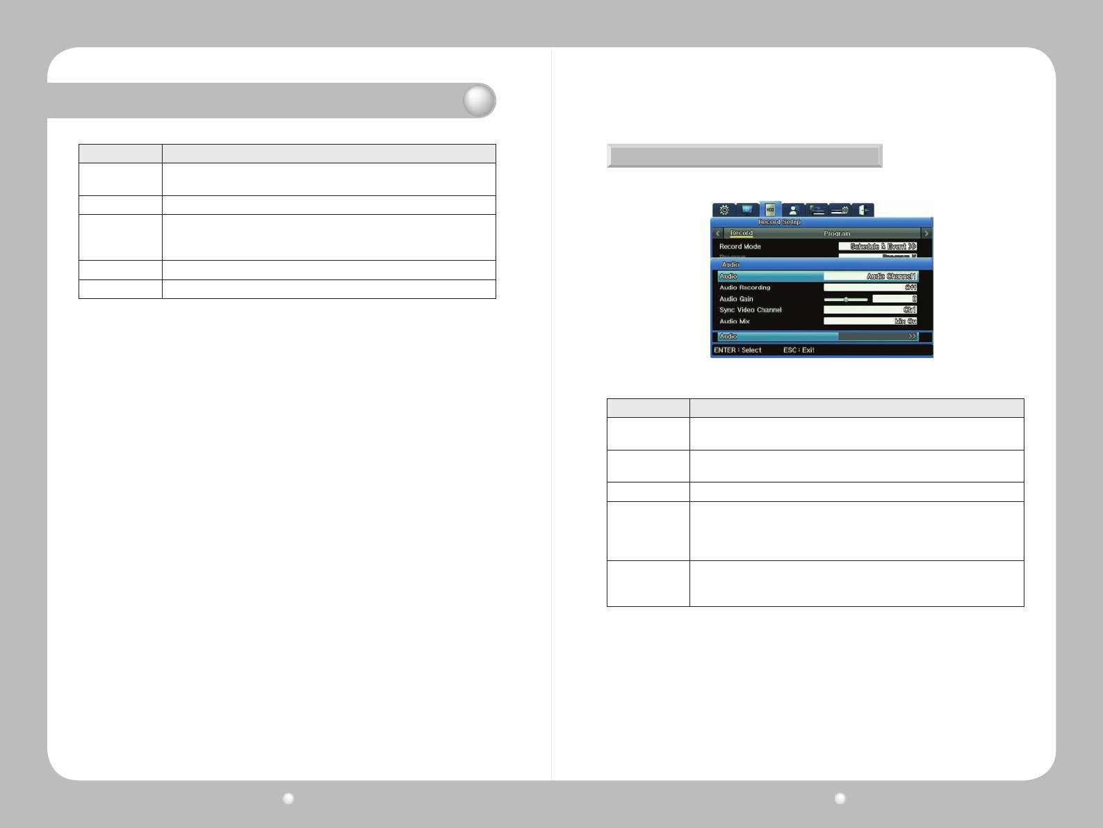
Digital Video Recorder User Guide
78
Digital Video Recorder User Guide
79
Chapter 8. Scheduling and Recording Video
Option Description
Index 1-50 different programs can be set. This allows you to set an variety of indexes for
various days, and portions of days, for each week.
Day The day of the week this Index is in affect.
Program
The Program you wish to use for the Index.
To see the definition of any particular Program, go to Program submenu on the
Record Setup menu of the OSD. Also refer to Defining Programs on page 69.
Time Time of day. (In the grid, 0 means Midnight, 12 means Noon, and so on.)
Delete Click the Delete button if you want to erase the Index entries from the grid.
How to Set up a Schedule
1.Inthedataeldsatthetopofthesubmenu,entertheIndex,theDayandtheProgram.
2.IntheTimedataeld,enterthehouratwhichyouwanttheprogramtobeginrecording,andthe
time at which you want data to cease recording.
-You’llseethegridautomaticallydisplaythehours,markedwiththeletterthatdesignatedthe
Program you chose.
Alternatively,youcansetdatainthegrid,andthedatawillappearalsointhedataelds.
A Brief Tutorial
1.OntheSchedulesubmenu,select1fortheIndex,SundayfortheDayandAfortheProgram.
2. For time, select 00:00 – 20:00.
-Noticethatthegriddisplaysan“A”onSundayfromMidnightuntil20:00
3.Nowselect2forIndex,TuesdayforDayandBfortheProgram.
4.DonotenteranythingintheTimesetting.
5.Usingyourmouseorthearrowsonthefrontpanel,navigatetotheTuesdayrow.Dragthemouse
alongtherow,orclickthearrowbuttons.TheTuesdayrowpopulateswith“B”program.
6.Nowhighlighta“B”intheTuesdayrow.
7.ClickanywhereintheMondayrow,andthe“B”willappearforthathour.NoticethattheIndex
dataelddisplaysanewIndexnumberforthatnewrow.
Deleting an Index Conguration
Ifyouwanttochangeanindex’scongurationafteryou’vesetitup,deletetheIndextoremoveits
current settings and erase it from the grid.
1.IntheIndexdataeld,selecttheIndex.
2.ClicktheDeletebuttontodeleteit.
3.The Index conguration is erased. You can now set different congurations for that Index
number.
※TIP:BecausetheIndexeldisneverempty,besuretodouble-checkthatyouaredeletingthe
appropriateindex.WhenyouclicktheDeletebutton,whateverIndexisdisplayedinthe
Indexeldwillbedeleted!
Audio Setup
YousetupAudiosettingfromtheAudiooptionontheRecordsubmenu.
Figure 8.7.3 Audio Channel submenu on the Record submenu
Option Description
Audio Channel Select a channel for audio. (This is not the channel for video; set that under Sync
Video Channel.)
Audio Recording Set Yes to have audio recorded for playback. (If you set it to Off, audio is still
available for live video.)
Audio Gain Adjust audio volume up or down.
Sync Video
Channel
Select the video channel for which you are setting audio.
By default, Channel 1 audio is outputted to Channel 1 video. But you can set, for
example, the Audio Channel to Ch1 and set the Sync Video Channel to Ch8. Then,
Channel 1 audio will be associated with Channel 8 video.
Audio Mix
On this submenu, set the audio for live feeds.
· Set to Mix On to have all audio available for output regardless of channel.
· Select a specific channel to mix audio for that channel only.
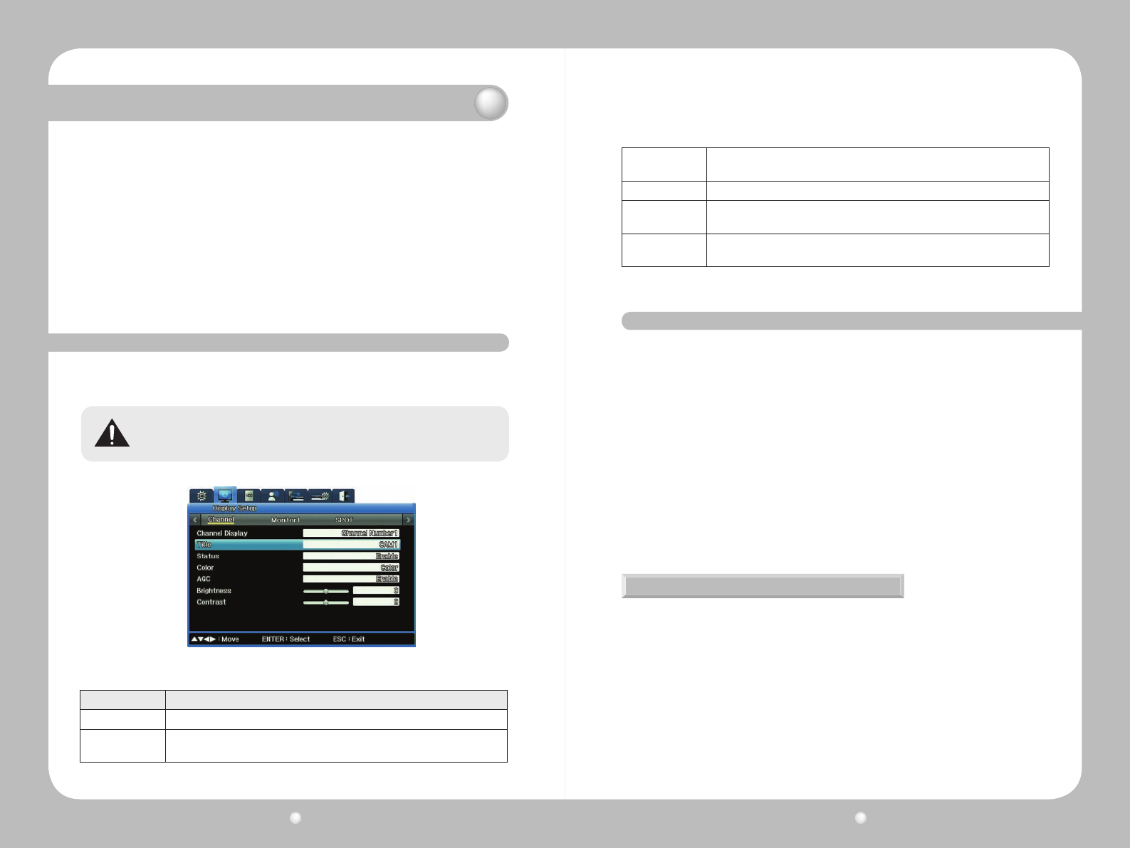
Digital Video Recorder User Guide
80
Digital Video Recorder User Guide
81
Chapter 9. Camera and Monitor Display Setup
This chapter provides information about setting up the camera and monitor displays, and
thescreenlayout,sequencingandotherfeaturesavailablewhenviewingvideoimagesfrom
camerasconnectedtotheDVR.
The information is presented in these sections :
▶9.1SettingUptheCameraDisplay
▶9.2AboutMultichannelScreenDisplay
▶9.3SettingUptheMonitorDisplay
▶9.4UsingAutoSequencing
▶9.5ConguringMultiDisplayLayouts
9. 1 Setting Up the Camera Display
You congure each camera connected to the unit using the Channel Display submenu. You can adjust
Title, Status, Color, AGC, Brightness or Contrast for each of the cameras.
Use only one type of camera—either NTSC or PAL—on the DVR.
Figure 9.1.1 Channel Display submenu on the Display Setup Menu
Option Description
Channel Number Assign the channel to a camera.
Title Give a name to the camera for that channel. (This setting opens the On screen
keyboard in which you can enter what you want to call the camera)
Status Enable or disable a camera. To increase recording or network monitoring speed, be
sure to disable unused channels.
Color Select Color or B/W.
AGC (Auto Gain
Control) Set the automatic input range of video signals from a camera.
Brightness and
Contrast Adjust the brightness and contrast of a video.
9. 2 About Multichannel Screen Display
You can change your screen display from a single channel to various congurations on multiple
channels on a split screen, up to all 16 channels on a split screen. (The default setting is 16
channels.)
You view multiple channels in various congurations on a split screen. For some of these, the channels
are standard. For others, you set up which channels you want to appear.
4A — Channels 1, 2, 3 and 4
4B — Channels 5, 6, 7 and 8
4C — Channels 9, 10, 11 and 12
4D — Channels 13, 14, 15 and 16
4E — Any four channels you specify
9A — Channels 1, 2, 3, 4, 5, 6, 7, 8, 9
9B — Any nine channels you specify
10A — Any 10 channels you specify
Changing Screen Display
Shifting from multichannel to single channel
There are two ways to shift a multichannel display to single screen display of one channel :
∙Onthefrontpanel,pressthechannelbutton.Forexample,pressthe“3”toviewchannel3in
single-screendisplay.
∙HoverthemousecursorovertheChannelimageonthescreen,andthenleft-clickthemouse.
∙Placeyourmousecursoronthechannel’simageonscreen,andleft-click.
Toreturntosplitscreendisplay,presstheMULTIbuttonorleft-clickthemouse.
Using the MULTI button on the front panel
Onthefrontpanel,presstheMULTIbutton.Eachtimeyoupressthebutton,thescreendisplaysa
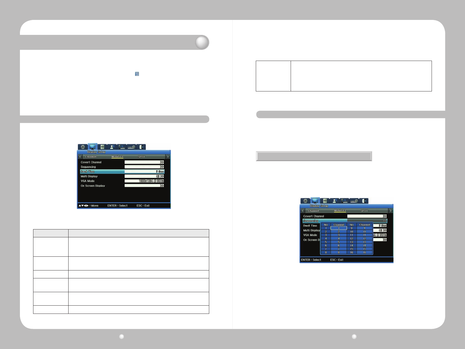
Digital Video Recorder User Guide
82
Digital Video Recorder User Guide
83
different layout on the split screen :
UsingtheMULTIbuttonontheFunctionmenu.
1.OpentheFunctionMenuandpresstheMULTIbutton .
2.Alistoflayoutcongurationoptionsdisplaysonscreen.Selectthelayoutyouwishtosee.
Forexample,ifyouselect“11,”channel11willdisplayinfullscreen.Ifyouselect“9A,”the
screenwillsplittoshowthose9channels.
3.PressESCtoclosethemenu.
Chapter 9. Camera and Monitor Display Setup
9. 3 Setting Up the Monitor Display
You congure the display for each monitor using the Monitor submenu.
Figure 9.3.1 Monitor submenu on the Display Setup Menu
Option Description
Monitor Number
Select the monitor you want to configure.
Monitor 1 is available for all supported DVR functions. Monitors 2, 3 and 4 are
available for live viewing and recording, but not available for playback and search.
Covert Channel Set any video channel you want to remain private and accessible only with specific
permission. This channel will be hidden in live and playback modes.
Sequencing Set the order in which monitor images display in an auto sequence.
Dwell Time Set the amount of time a monitor image displays before the next image in the auto
sequence appears.
Multi Display Select the monitor images you want to appear for the split screen configurations
4E, 9B or 10A.
VGA Mode Enter the dimensions of your monitor.
On Screen Display
Select information you want to show, superimposed on the video:
· For live video feeds, you can set the time, channel name, event, recording status,
HDD usage, remote control ID and text.
· For video playback, you can set the time, command, channel name, event and
text display.
9. 4 Using Auto Sequencing
Auto Sequencing automatically rotates display of the live feeds from cameras. You can set up the 16
“spots” in the rotation. Each camera’s image displays in the order you determine, for the amount of
time you set (as the Dwell Time option). After each image displays in sequence, the rotation begins
again and plays continuously until you stop it.
Setting up Auto Sequencing
YousetupautosequencingwhileenteringsettingsfortheoptionsontheMonitorsubmenuof
the Displays Settings menu :
1.OntheMonitorsubmenu,selecttheMonitorforwhichyouaresettingoptions.
2.SelecttheSequencingoption.TheSeqscreenappears.
3.Setthechannelyouwanttoappearrst,second,thirdandsooninthesequence.Youcanset
upto16channels(orlessifyouwish).
Figure9.4.1showssomedenedsequences:
·FirstinsequenceisChannel1.Channel1willappearinsinglescreen.
·Secondinsequenceis16Div.All16channelswillappearonasplitscreen.
·Thirdinsequenceis4A.Thefour4Achannelswillappearinsplitscreen.
Figure 9.4.1 Sequencing submenu
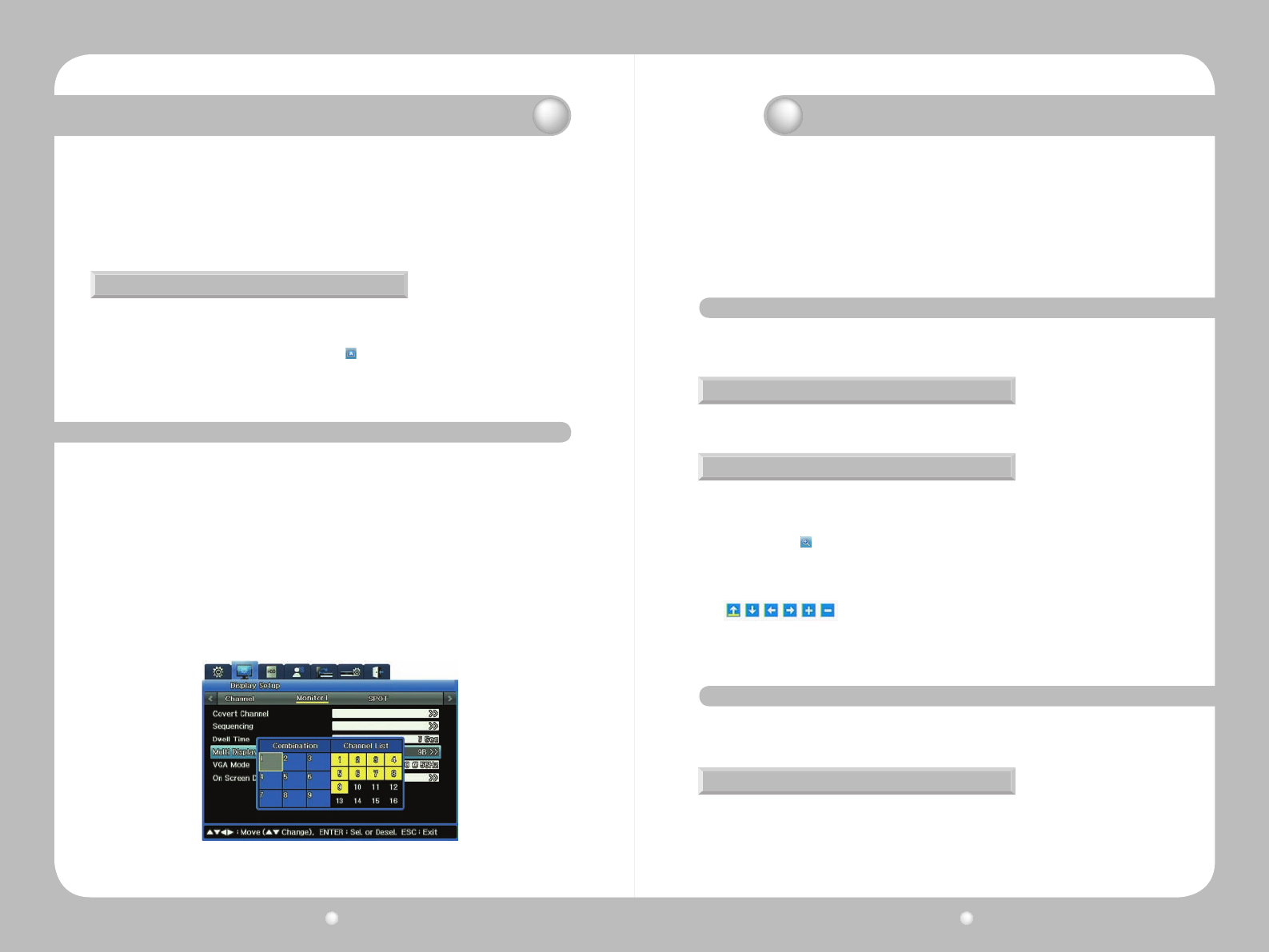
Digital Video Recorder User Guide
84
Digital Video Recorder User Guide
85
4.Onceyouhavesetupthesequences,closetheSeqsubmenutoreturntotheMonitorsubmenu
to set the Dwell Time.
5. For the Dwell Time option, enter the amount of time you want each channel to appear on the
monitor(from1to60seconds).
·YoumustsetaDwellTimetoactivateAutoSequencing.IfDwellTimeissettoOff,Auto
Sequencingwillnotwork.
Running Auto Sequencing
TherearetwowaystoturnonAutoSequencingsoyoucanviewitonyourmonitor:
·Onthefrontpanel,presstheAUTObutton.
·OntheFunctionKeymenu,presstheAutobutton .
TostopAutoSequencing,presseitherbuttonagain.(Thisstopsitfromrunning;itdoesnot
erase your settings.)
9. 5 Configuring Multi Display Layouts
You can congure which channels you want to display in the 4E, 9B and 10A multichannel setting.
You set up multi display while entering settings for the options on the Monitor submenu of the Displays
Settings menu :
1.OntheMonitorsubmenu,selecttheMonitorforwhichyouaresettingoptions.
2.FortheMultiDisplayoption,selectrstthecongurationyouwanttoset:4E,9Bor10A.
3.Next,accesstheMultiDisplaysubmenu.
TheMultiDisplaysubmenushowsgridappropriatetothecongurationyouselected:splitby
4,splitby9,orsplitby10.
4.ClickintheChannel’sboxforeachchannelyouwanttoincludeinthemultidisplay.For
example,ifyouaresettingupa9B,select9channels.
-Thegriddisplayswherethechannel’simagewillappear.
-Theorderinwhichyouclicktheboxesistheorderinwhichthechannelsappearonthegrid.
Figure 9.5.1 Multi Display Layouts
Chapter 10. Camera Commands
Thischapterexplainshowyouexecutevariouscameracommands,whileviewinglivevideo,
fromcontrolsontheFUNCmenuandonthePTZmenu.
The information is presented in these sections:
▶10.1CameraCommandsfromtheFUNCMenu
▶10.2Pan/Tilt/ZoomCommands
10. 1 Camera Commands from the FUNC Key Menu
10. 2
Pan/Tilt/Zoom Commands
While viewing live video, you can use the FUNC menu pause the video and zoom in on the image.
If you connect a PTZ controller to you PTZ camera, you can control pan, tilt and zoom while watching
live video. Once you have the controller congured, you can access and work with the PTZ menu.
Pausing Live Video
Accessing the PTZ Menu
Zooming In on Live Video
Topauselivevideo,pressthePAUSEbutton.Pressthebuttonagaintoresumelivevideo.
1. Press the channel button to select the channel you wish to view.
2.PresseitherthePTZbuttonortheFUNCbuttononthefrontpanel.
3.ThePTZmenuappears,superimposedonthecamera’simage.
Whenviewingasinglechannelinfull-screenmode,youcanzoominontheimage.Zooming
allowsyoutomovein18levelshorizontallyand12levelsvertically.
1.PressFUNCtoaccesstheFunctionmenu.
2.SelecttheZoom button.
· The camera location defaults to the center of the screen.
3.Selectthe“Plus”buttonandpressENTERorleft-clickthevideopane.
·Torepositiontheimage,usethenavigationkeysontheFUNCmenu:
Chapter 9. Camera and Monitor Display Setup
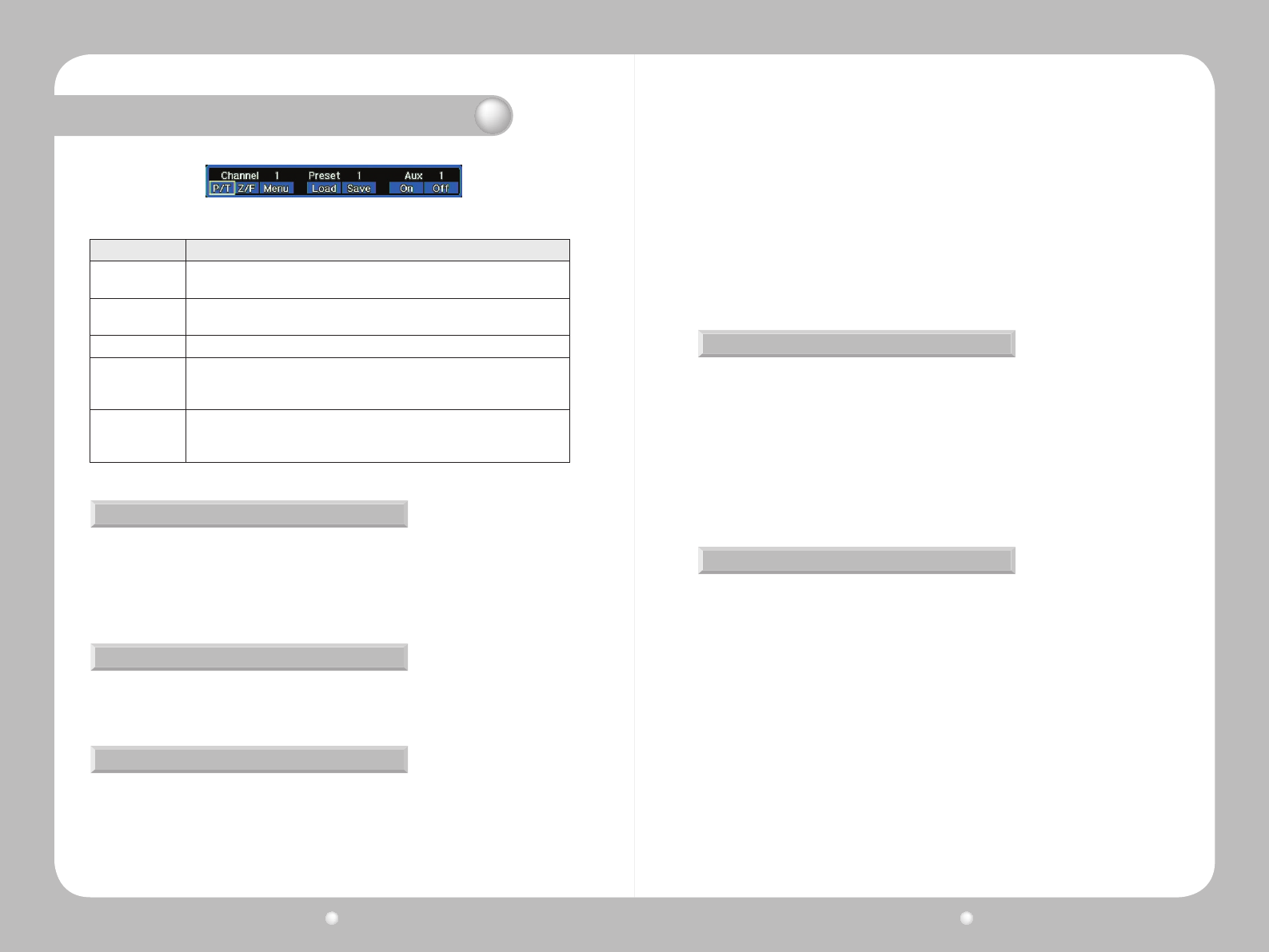
Digital Video Recorder User Guide
86
Digital Video Recorder User Guide
87
Figure 10.2.1 PTZ Menu
Option Description
P/T P/T stands for Pan/Tilt. Select this button to operate the Pan or Tilt features of the
camera.
Z/F Z/F stands for Zoom/Focus. Select this button to operate the Zoom or Focus
features of the camera.
Menu Opens the PTZ menu. To exit the menu, press the PTZ button on the front panel.
Preset
with Load and
Save
You can define where and how you want the camera to position itself.
Aux
with On and Off
Aux stands for Auxiliary, meaning special functions of your particular brand or
model of PTZ camera. For this option, you enter the number that corresponds to
the particular auxiliary function you want to use.
Using Pan/Tilt
Using Zoom/Focus
Loading and Saving Presets
Topanortiltacamera,selectP/TfromthePTZmenu.
· To pan the camera, press the left or right arrow key on the front panel, or click the left or right
area of the screen.
· To tilt the camera, press the up or down arrow key on the front panel or click the top or bottom
of the screen.
Tozoomorfocusacamera,selectZ/TfromthePTZmenu.
·Usethemouseofthebuttonsonthefrontpaneltozoomorfocusontheimage.
Apresetisadenedcameraposition;youpresetthecameraangleandfocus.
YoumustrstsetupcamerapresetwithPTZattachedtoeachchannel.
To activate a preset location :
1.GotothePTZmenu.
2. Select a preset number.
3.SelectLoadandthenpresstheENTERbutton.
Thecamerawillpan,tiltorzoomtothespecicationsofthatpresetcondition.
To save a position—in other words, to make it a preset :
1.Pan,tiltandzoomthecamerauntilitadjustedtothepositionyouwanttosave.
2.GotothePTZmenu.
3.InthePreseteld,selectapresetnumber.
4.SelectSaveandthenpresstheENTERbutton.
Setting Auxiliary Functions
Setting the Console Menu
TheAuxiliaryfeatureisusedforspecialfunctionsofaPTZcamera.Specicfeaturesdepend
ontheparticularmakeandmodelofcamerayouareusing.Refertothemanufacturer’s
documentationforinformationonauxiliaryfunctions.
To use the Auxiliary function :
1.GotothePTZmenu.
2.ToturnontheAuxiliaryfunction,selectOn.
3.Setupto16Auxiliarynumbers.
4.ToturnoffanAuxiliaryfunction,selecttheAuxiliarynumberyouwishtoturnoffandselectOff.
IfthePTZcameraisconnectedtotheDVRwiththeSamsungSPDprotocol,youcancongurethe
camera using its console menu.
To access a camera’s console menu :
1.Usethenavigationkeysonthefrontpaneltoselectcamerasettings.
2.PressENTERtoacceptyoursettings.
Chapter 10. Camera Commands
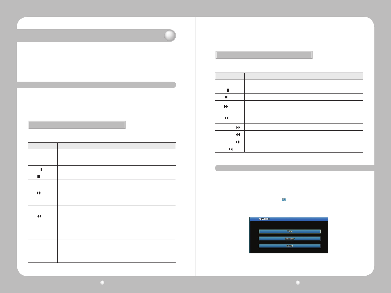
Digital Video Recorder User Guide
88
Digital Video Recorder User Guide
89
Chapter 11. Working with Recorded Video
ThischapterdiscussedworkingwithvideothathasbeenrecordedontheDVR.
The chapter covers these topics :
▶11.1VariousPlaybackOptions.
▶11.2SearchingforRecordedVideo
▶11.3AboutCopyingVideo
11. 1 Various Playback Options
To begin playback of recorded video on a 16-channel split screen, either :
• Press the PLAY button on the DVR’s front panel;
• Press the Play button on the remote control;
• On the Function Key menu, press the Play button.
Controlling Playback with Function Menu
UsethesekeysontheFunctionmenutocontrolplayback:
Option Description
Play
▶
Plays a video at 1x speed.
· Press PLAY in monitor mode to play multiple videos.
· Press PLAY to play recorded videos from the last playback timestamp.
Pause
Press to pause video playback.
Stop
Press to stops video playback.
Fwd
Press FWD while viewing a live feed to play the video recorded one minute before
the current live time.
Press FWD on the Function menu to change the playback speed. Each time you
press FWD the playback speed changes in this sequence: x1, x2, x4, x8, x16, x32,
x64, x1/2.
Rew
Press REW while viewing a live feed to play the video in reverse from the last
recorded frame.
Each time you press REW, the video plays in reverse playback speed (in the order
of x1, x2, x4, x8, x16, x32, x64, x1/2)
1/2
◀
Press ½ Rewind to play the video at half speed.
▶
1/2 Press ½ Forward to play the video in reverse at half speed.
Step Forward Press PAUSE than FWD to play the video frame by frame.
Press the PLAY button to return to normal playback.
Step Rewind Press PAUSE, then REW, to play video frame by frame in reverse.
Press the PLAY button to return to normal playback.
Controlling Playback with Remote Control
If you use the remote control device, use these keys to playback video :
Option Description
Play
▶
Plays a video at 1x speed.
Pause
Press to pause video playback. Press Enter to resume play.
Stop
Press to stops video playback.
Fwd
Press FWD while viewing a live feed to play the video recorded one minute before
the current live time.
Rew
Press REW while viewing a live feed to play the video in reverse from the last
recorded frame.
Step Forward IPlays video frame by frame.
Step Rewind
I
Plays video frame by frame in reverse.
Fast Forward Forwards video rapidly.
Rewind
Rewinds video rapidly.
You can search for recorded video by Time, Calendar, Event and Thumbnail. To go to Search mode,
either :
• Press the SEARCH button on the front panel.
• Press the SEARCH key on the remote control.
• On the Function Key menu, click the Search button.
The Search menu appears, and from it you can select the type of search you wish to perform.
11. 2
Searching for Recorded Video
Figure 11.2.1 Search Menu
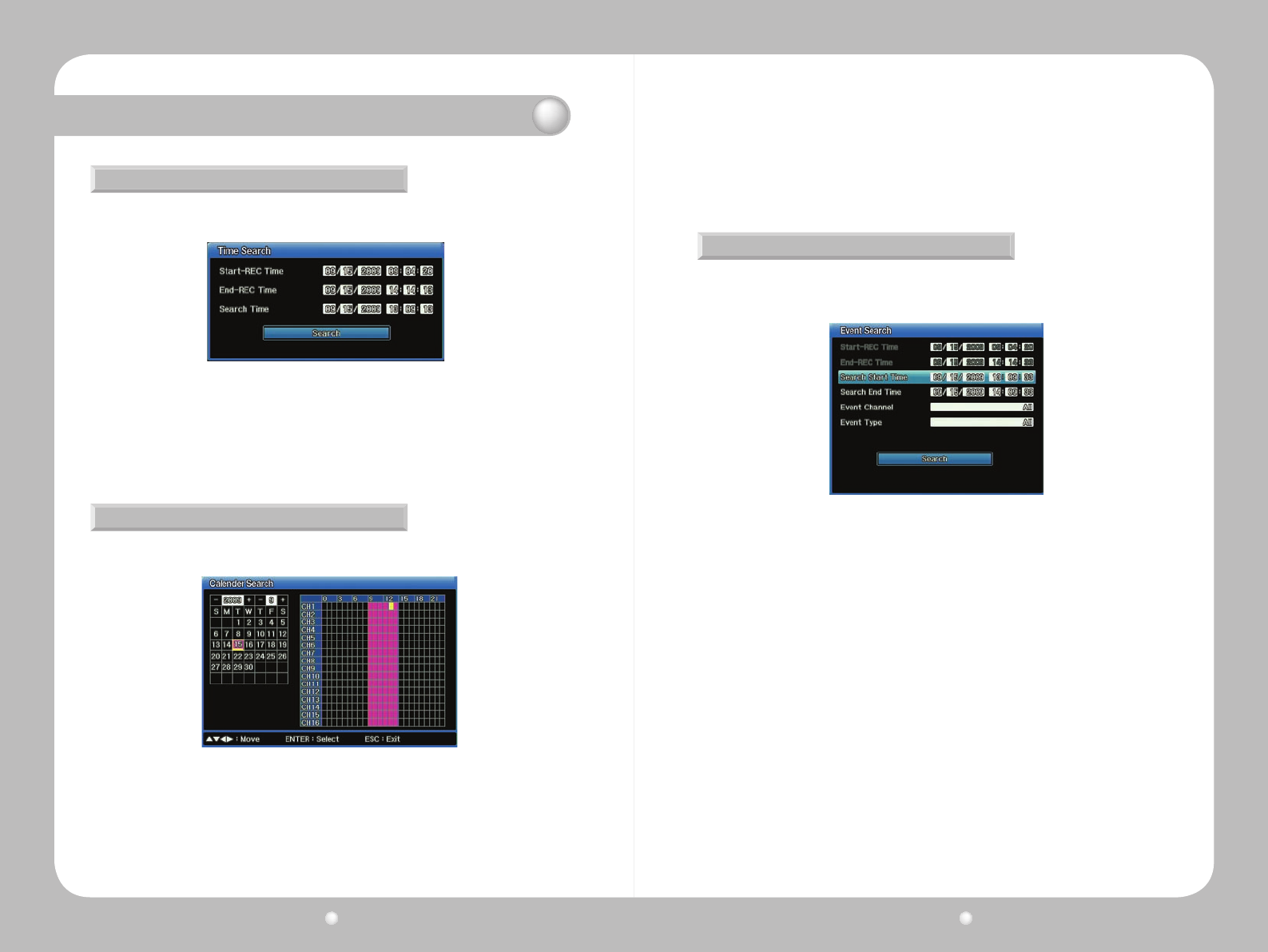
Digital Video Recorder User Guide
90
Digital Video Recorder User Guide
91
Chapter 11. Working with Recorded Video
Searching by Time
Searching by Calendar Date
1.SelectTimefromtheSearchMenu.
1.SelectCalendarfromtheSearchMenu.
2.IntheYeareldselecttheyear.
3.IntheMontheld(totherightofYear),selecttheMonth.
4.Inthemonthgrid,selectthedatewithinthatmonth.(Ifadateinunderlinedinpink,videowas
recorded on that date.)
5.Inthetimeperiodgrid(attheright),selectthetime.Thegridinmarkedbyhours:0isMidnight,
2.NoticethattheStart-RECtimeandEnd-RECTimeeldshowtherangewithinwhichyoucan
search.
3. In the Search Time selection, enter the date and time you want to search for.
4.SelectSearchtostartthesearch.
Figure 11.2.2 Time Search Menu
Figure 11.2.3 Calendar Search Menu
12isNoon,andsoon.Ifanhourismarkedinpink,videowasrecordedinthathour.
6.PresstheENTERbuttontostartplaybackofthevideoforthedateandtimeyou’veselected.
Searching by Event
Youcansearchforeventsthatoccurredataspecictimedowntothesecond.
1.SelectEventfromtheSearchMenu.
2.NoticethattheStart-RECtimeandEnd-RECTimeeldshowtherangewithinwhichyoucan
search.
3. For the Search Start Time, enter the date and time on which you want to begin the search.
4.FortheSearchEndTime,enterthedateandtimeonwhichyouwantsearchto.
5.ForEventChannel,selectonwhichchannelsyouwanttosearch.
6.ForEventType,selectwhichtypeofeventyouwanttosearchfor—Text,VideoLoss,Sensor,
MotionDetection,orAll
7.SelectSearchtostartthesearch.
8.Alistwillappearwiththesearchresults.Selectanitemfromthelisttostartplayback.
Figure 11.2.4 Event Search Menu
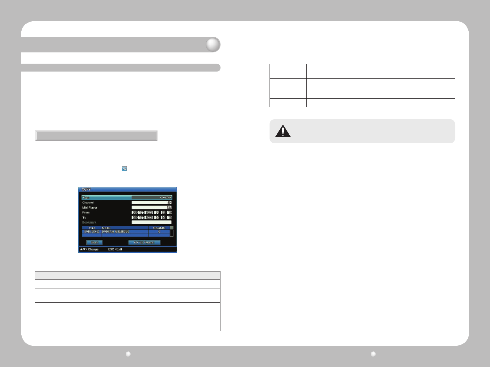
Digital Video Recorder User Guide
92
Digital Video Recorder User Guide
93
The SVR 1680/1660 allows copying to three types of media.
• CD/DVD : You can copy video to a CD or DVD. We recommend you use the 16x CDs or DVDs from
Mitsubishi, TDK, Imation and Sony.
• STK : You can copy several channels of video to HDD or USB storage, to play them using the mini
player or network manager.
Only users with correct security permissions can use the Copy function.
11. 3 About Copying Video
Copying Video
To being copying, either :
·PresstheCOPYbuttononthefrontpanel.
·PresstheCOPYkeyontheremotecontrol.
·OntheFunctionKeymenu,selecttheCopy button.
ThenentertheappropriateselectionsforeachoptionontheCopymenu.
Figure 11.3.1 Copy Menu
Option Description
Type Select either CD/DVD, STK.
Channel For CD/DVD and STK, open the Copy Channel List and check the channels you
want to copy.
From Enter the start date and time of the video you want to copy.
To
or
Duration
For CD/DVD and STK, enter the end date and time of the video you want to copy.
Select Disk This option will show the media currently inserted into your DVR. Select the disk
you want to copy to.
FAT32 Format
If you are using unformatted USB or HDDs in FAT32, you must format them before
copying. Select the FAT32 Format button to format them. (This applies only to STK
copying, not to CD/DVDs.)
Start To being the copying, select the Start button.
Do not interrupt the copying process once it begins. If the copy process is not 100%
complete, the copied video will not play properly.
Chapter 11. Working with Recorded Video
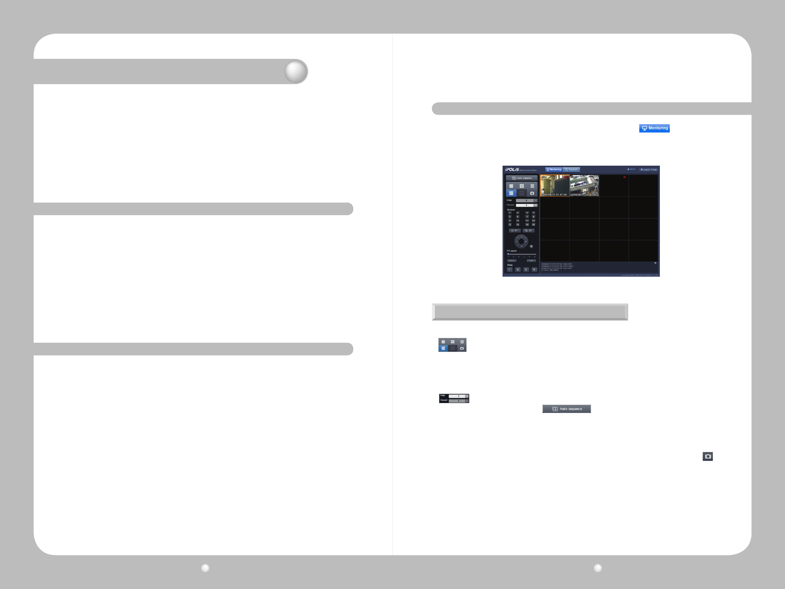
Digital Video Recorder User Guide
94
Digital Video Recorder User Guide
95
Chapter 12. Using Web Viewer
This chapter provides information about Web Viewer, an online application which serves as a
complementtotheDVR.WithWebViewer,youcanviewvisuallivefeedsandplayrecordeddata
over the Internet.
The information is presented in these sections :
▶12.1SystemRequirements
▶ 12. 2 Starting Web Viewer
▶12.3MonitoringLiveVideo
▶12.4WorkingwithRecordingVideo
12. 1 System Requirements
12. 2 Starting Web Viewer
To use Web View, we recommend that your system meet these requirements :
•CPU : Core2duoE6750orhigher
(IntelPentium4/3.0GHzistheminimumacceptable)
•Operating System : WindowsXPProfessionalorWindowVistaBusiness
•Main Memory : 2GBormore(1GBistheminimumacceptable)
•Video Memory : 512MBormore(128MBistheminimumacceptable)
•Display Resolution : 1280x1024(32bitcolor)orhigher
•HDD : 1GBormore
•Other : DirectX9.0orhigher,WindowsInternetExplorer6.0orhigher
Follow these steps to start Web Viewer :
1. Close all open programs.
2. Open your browser and enter the IP address and port assigned to the DVR, for example: http://xxx.
xxx.x.xxx:4000.
The port value default is 4000. Use this default unless your system administrator has changed the
value, in which case use that new value.
3. The Login screen appears.
- If you do not have ActiveX installed on your computer, you will be prompted to install it. The
ActiveX program is required to run Web Viewer.
4. At the Login screen, enter your ID and password.
- The default ID is admin.
- The default password is 11111111 (eight ones).
5. Click Login.
If you are logging into Web Viewer for the rst time, or if you click the button at the top
of Web Viewer, you will be directed to the Monitoring Page where you can view the video feeds from
the cameras connected to your product.
12. 3 Monitoring
Splitting the Screen, Changing Channels & Screen Capture
Youcanselectthenumberofvideofeedstosimultaneouslydisplayon-screenbyclickingthe
buttonintheupperleftofthescreen.1,4,9,and16channelsareavailabletomonitor
simultaneously.
Whendisplaying1,4,9,or16channelsatthesametime,thechannelsaredisplayedin
groupstomanagevisibility.Forexample,ifyouaremonitoring9channelssimultaneously,
thenchannels1~9aredisplayedingroup1,andchannels10~16aredisplayedingroup2.
is used to select the group or channel you want monitoring. To watch video in all
channelsinsequentialorder,click buttontoactivatetheAutoSequenceoption
thatcyclesthroughvideosindifferentchannelsat7-secondintervals.
Thelogsforthecurrentchannelareatthebottomofthescreen:event(MD,V-Loss),mainunit
sensor, and relay event. To check the logs, move the scroll on the right side of the window up or
down.TheeventicondisplaysonthevideoofchannelswhereMD,V-LossandSensoroccur.
When clicking on a video channel, the selected screen is outlined in orange. To save the
selectedscreenasaJPGle,presstheleftbuttononthepagewhiletheorangeoutlineis
present.
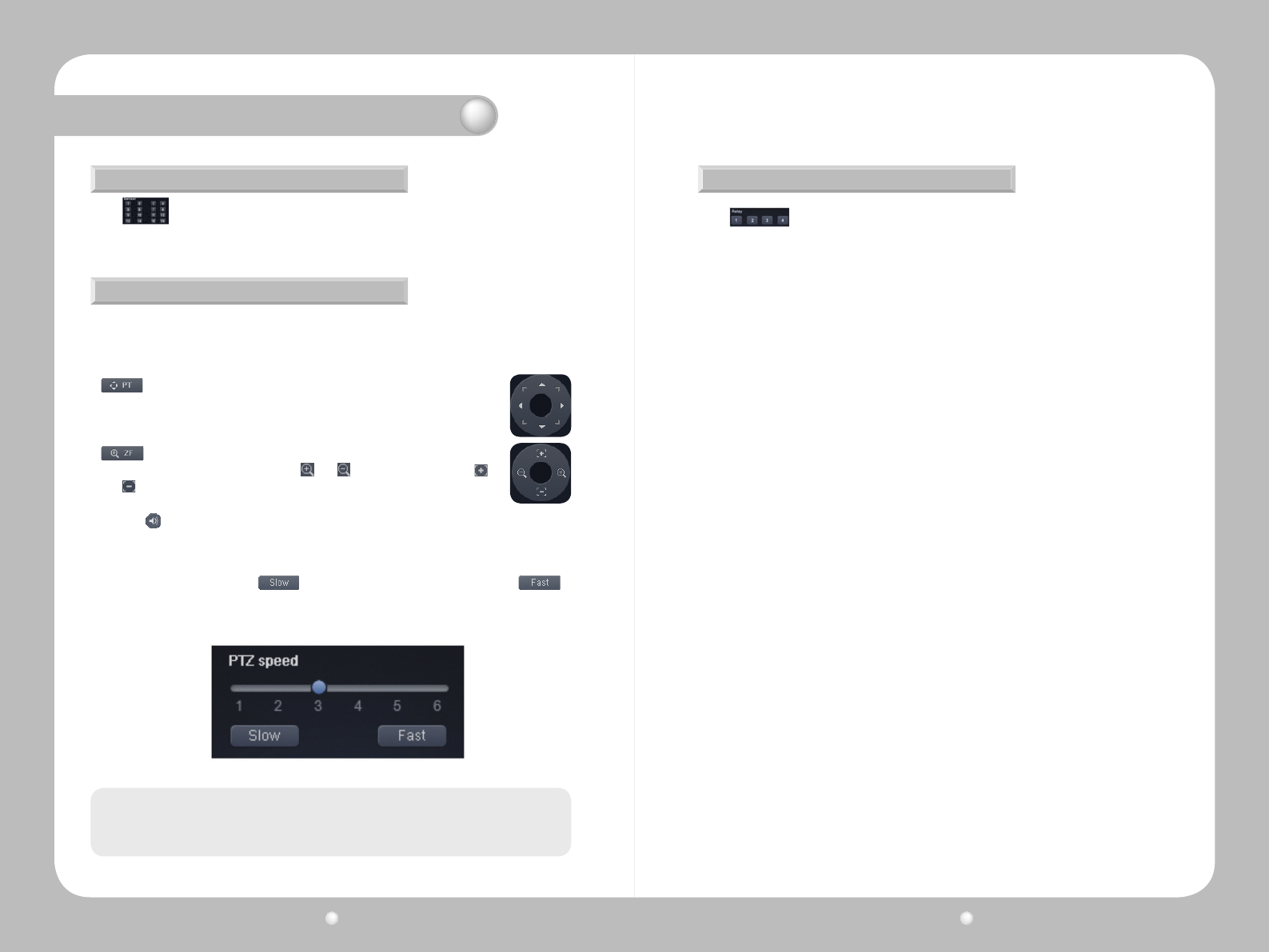
Digital Video Recorder User Guide
96
Digital Video Recorder User Guide
97
Sensor Status
PTZ Control
The window on the left side of the screen displays the status of sensors.
When clicking on a video channel, the selected screen is outlined in orange. To control the
cameraPTZ(Pan,Tilt,Zoom)operationsoftheselectedchannel,presstheleftbuttononthe
page while the orange outline is present.
Clickthe buttonnexttothecircularbuttontoplaytheaudiofeedfromtheselectedchannel.
TheeffectofthisbuttonisidenticaltotheAudiooptionintheright-clickcontextmenu.
changesthedirectionthatthecamerafaces.Clickthebuttontodisplay
thecircularbuttonshownontheright.Clickadirectiononthecircularbuttonto
pan the camera in that direction.
adjuststhezoomandfocusofacamera.Clickthebuttontodisplaythe
circularbutton,shownontheright.Click and tozoominandout;click
and toadjustthefocus.
YoucanadjustthePTZspeedwiththeslideratthebottomofthepage.Atotalof6differentPTZ
speedlevelsareavailable.Click todecreasethePTZspeedbyonelevel,and
toincreaseitbyone."1"istheslowestPTZspeedsetting,and"6"isthefastest.
Chapter 12. Using Web Viewer
The PTZ control and preset options are only compatible with PTZ enabled cameras, and the
DVR must be configured with the correct settings.
Note
Control Relay
The window on the left side of the screen displays the status of currently activated
relays.Usethenumberbuttonsinthewindowtocontrolcorrespondingrelays.
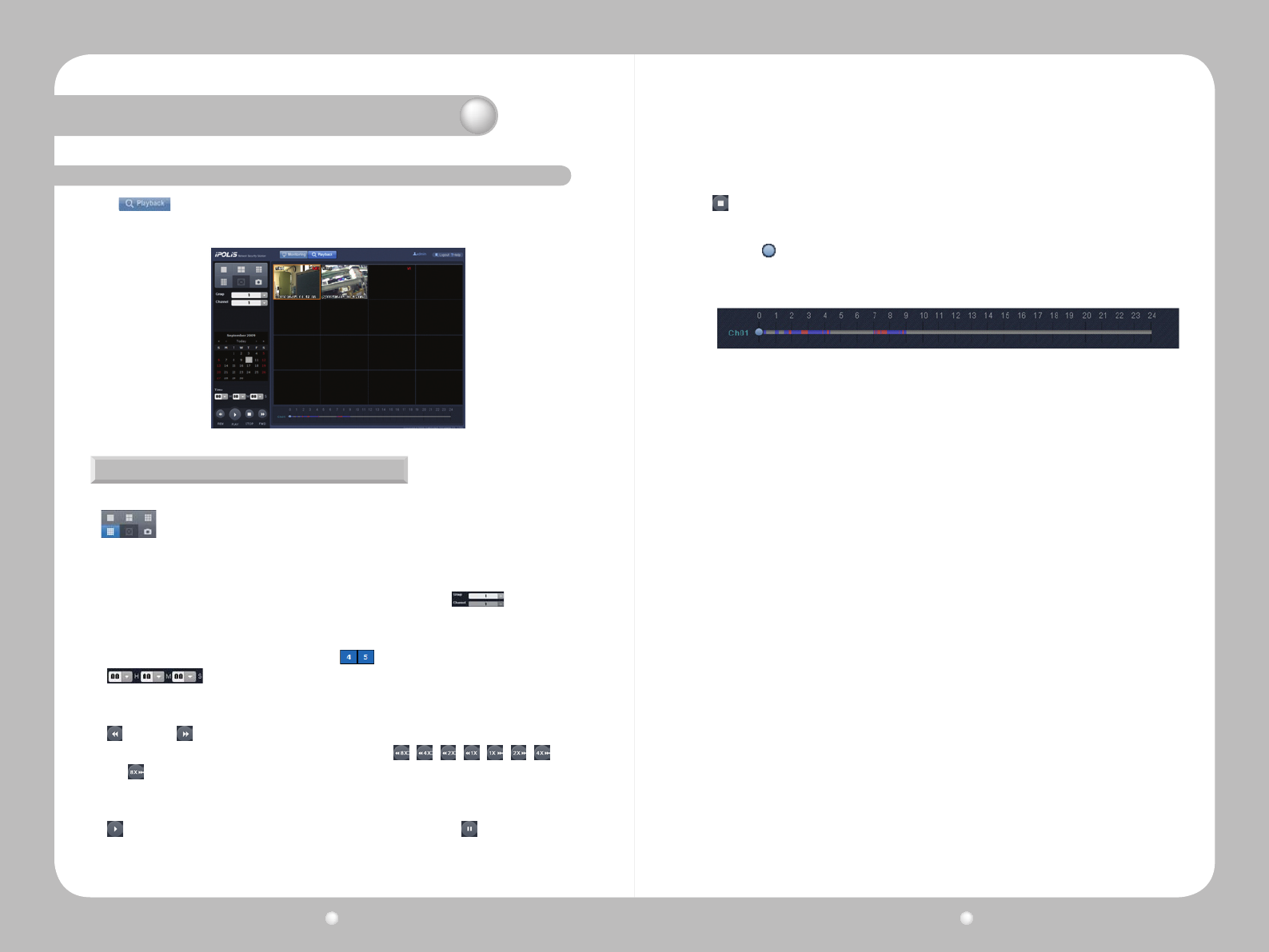
Digital Video Recorder User Guide
98
Digital Video Recorder User Guide
99
12. 4 Playback
Click at the top of the screen to display the Playback screen. This screen lets you watch
saved videos. Playback uses the Time Search option.
Splitting the Screen, Changing Channels, & Screen Capture
Youcanselectthenumberofvideofeedstosimultaneouslydisplayon-screenbyclickingthe
buttonintheupperleftofthescreen.1,4,9,and16channelsareavailabletoplay
video simultaneously.
Whenplayingvideofrom1,4,9,or16channels,thechannelsaredisplayedingroupstomanage
visibility.Forexample,ifyouareviewing9channelssimultaneously,thenchannels1~9are
displayedingroup1,andchannels10~16aredisplayedingroup2.Use to select and
play video from a desired group and channel.
·Towatchavideoconveniently,selectadateonthecalendarundertheChannelbutton.Dates
with videos available are displayed in blue, e.g.
· TimeArea:Whilethevideoscreenispaused,selectingatimeandclicking
the Play button plays a video at that time. While a video is being played, the Time area displays
the recorded time of the video.
· REWand, FFWButtons:Rewind,fastforward,andadjusttheplayspeedofthecurrent
video. While a video is being played, the buttons change to , , , , , , ,
and ,indicatingtheplaydirectionandspeed.Theadjustedplayspeedsare1x,2x,4x,and
8xbackwardandforward.EachtimetheREWorFFWbuttonisclicked,theplayspeedchanges
by one level.
· PLAYButton:Playsavideo.Whileavideoisplaying,itchangestothe (PAUSE)button.
·Movethe knobonthesliderbelowtheplaybackscreentoseektoaspecicvideotime.
Times with video available are highlighted in blue on the time slider while times with event
video are in red.
Chapter 12. Using Web Viewer
ClickingthePAUSEbuttonpausesthecurrentvideo.
· StopButton:Stopsavideo.

Digital Video Recorder User Guide
10 0
Digital Video Recorder User Guide
101
Display
Specifications of the SVR-1670
Appendix A. Specifications of the SVR-1670
1. Video
a.Inputs 16compositevideo1Vpp,75ohmautomatictermination
Resolution 704x480forNTSC;704x576forPAL
2. Live
a.Framerate 480fps
b.Resolution: 704x480forNTSC;704x576forPAL
c.MultiScreen 1/4/9/10/16
1.Recording
a.Compression H.264
b.RecordingRate NTSC:120fps704X480,240fps704X240,and352x
240,allat480fps
PAL:100fpsin704x576;200fpsin704x288;400fps
in352x288
c.Mode Manual,Schedule,Event,Emergency
d.Overwritemodes Continuous
e.Pre-Event Upto5sec.
f.Post-Event Upto60sec.
2.Search&Playback
a. Searchmode Date/time,Event,Calendar,Bookmark
Text(Exclusiveviewer)
b.Framerate 480fpsD1forNTSC,400fpsD1forPAL
c.Playbackfunction REW,FWD,Frameadvance
3.Network
a.Transmitspeed 50Mbps
b.Bandwidthcontrol Automatic
c.MultiStream H.264/JPEG
d.RemoteUsers Upto10simultaneoususers
e.Protocolsupport TCP/IP,DHCP,DNS,DDNS,HTTP,RTSP,ARP,ICMPandNTP
f.Monitoring Built-inWebserver
4.Storage
a.Max.Capacity 32TB
b.InternalHDD 4HDD
a.VGAAnalog RGB800x600,1024x768,1280x1024resolution
b.MainComposite 1BNC,Multi-screen,Menu,Playback
c.SubComposite 3BNCSpot(eventpop-up,displayswitching)
d.LoopOutputs 16Output,1Vpp,75ohm
2.Audio
a.Inputs 16input,30kohm,1Vpp
b.Output 1line,1Vpp
c.Compression ADPCM
d.Samplingrate 8kHz
3.Alarm
a.Inputs 16Input,NO/NC
b.Outputs Screwterminal4relayoutputs,NO/NC
c.Remotenotification Notificationviae-mail
4.Connections
a.Ethernet RJ4510/100/1,000Base-T
b.Serialinterface RS232C
c.PTZcontrolinterface RS485/RS422
d.PTZKeyboard RS485
e.USB 2USB2.0ports
f.eSATA 2ExternaleSATAports
g.ApplicationSupport ATM/POS,Mouse,RemoteController
5. Dome Protocols
a.SupportedPTZcameras SamsungTechwin,PelcoD,PelcoP,Coaxitron
Panasonic,Boach,SEC.(Itisexpectedtoapplyatalater
date.)
c.ExternalHDD ExternaleSATA2port
d.Back-upDVDWriter: DVD+R/DVD-R/CD-R
FileFormat:BMP,AVI,Proprietaryformat/JPG(Exclusive
viewer)
5. Security
a.PasswordProtection 10UserLevel
1.Monitors
Performance
Interface
Digital Video Recorder User Guide
102
Digital Video Recorder User Guide
103
1.Electrical
a.InputVoltage 100to240VAC;50/60Hz
b.Powerconsumption Max.65Wwith1xHDD;Max.50W
2.Environmental
a.OperatingTemp 32°F~+104°F(+5°C~+40°C)
b.OperatingHumidity 0%RH~60%RH
3.Mechanical
a.Dimensions 17.5x3.5x16inch(445x88x405mm)
b.Weight(1xharddisks) Approx.22.1lb(10kg)
c.Rackmountkit FormountingoneunitinanEIA19inchrack
General
Appendix B. Recording Program Default Settings
The following table lists the default settings for recording programs.
SVR-1670 Recording Programs
NTSC Normal Event
Resolution FPS Quality Resolution FPS Quality
A D1 7 Q5 D1 7 Q5
B D1 5 Q5 D1 7 Q5
C D1 5 Q4 D1 7 Q5
D D1 4 Q5 D1 5 Q5
E D1 5 Q4 D1 7 Q5
F D1 4 Q4 D1 5 Q4
G D1 1 Q4 D1 4 Q4
H D1 0 Q4 D1 7 Q5
I Half 10 Q5 Half 15 Q5
J Half 5 Q5 Half 20 Q5
K Half 4 Q5 Half 10 Q5
L Half 10 Q4 Half 20 Q5
NTSC Normal Event
Resolution
FPS
Quality Resolution FPS Quality
M Half 10 Q4 Half 15 Q5
N Half 5 Q4 Half 10 Q5
O Half 5 Q4 Half 10 Q4
P Half 4 Q4 Half 5 Q4
Q Half 1 Q4 Half 4 Q4
R Half 0 Q4 Half 7 Q5
S CIF 30 Q5 CIF 30 Q5
T CIF 20 Q5 CIF 30 Q5
U CIF 20 Q4 CIF 20 Q5
V CIF 10 Q4 CIF 15 Q4
W CIF 25 Q3 CIF 25 Q5
X CIF 10 Q3 CIF 10 Q4
Y CIF 1 Q4 CIF 3 Q4
Z CIF 0 Q4 CIF 7 Q5
SVR-1670 Recording Programs
PAL Normal Event
Resolution FPS Quality Resolution FPS Quality
A D1 6 Q5 D1 6 Q5
B D1 4 Q5 D1 6 Q5
C D1 4 Q4 D1 6 Q5
D D1 3 Q5 D1 4 Q5
E D1 4 Q4 D1 6 Q5
F D1 3 Q4 D1 4 Q4
G D1 1 Q4 D1 3 Q4
H D1 0 Q4 D1 6 Q5
I Half 8 Q5 Half 12 Q5
J Half 4 Q5 Half 16 Q5
K Half 3 Q5 Half 8 Q5
L Half 8 Q4 Half 16 Q5
M Half 8 Q4 Half 12 Q5
Appendix A. Specifications of the SVR-1670
Digital Video Recorder User Guide
104
Digital Video Recorder User Guide
105
PAL Normal Event
Resolution FPS Quality Resolution FPS Quality
NHalf 4 Q4 Half 8 Q5
OHalf 4 Q4 Half 8 Q4
PHalf 3 Q4 Half 4 Q4
QHalf 1 Q4 Half 3 Q4
RHalf 0 Q4 Half 6 Q5
SCIF 25 Q5 CIF 25 Q5
TCIF 16 Q5 CIF 25 Q5
UCIF 16 Q4 CIF 16 Q5
VCIF 8 Q4 CIF 12 Q4
WCIF 21 Q3 CIF 21 Q5
XCIF 8 Q3 CIF 8 Q4
YCIF 1 Q4 CIF 3 Q4
ZCIF 0 Q4 CIF 6 Q5
Appendix B. Recording Program Default Settings
Appendix C. Supported PTZ Controllers and Protocols
ThistableliststhePTZcontrollersthatcanbeusedwiththeSVR1670DVR.
Someprotocolsareexpectedtoapplyatalaterdate.
Manufacturer Product
SAMSUNG
TECHWIN
· SDZ160/330
· Samsung SPD
· Keyboard SCC3000
· Samsung SRX-100B
BOSCH · BOSCH AutoDome
· TC8560X-4
PELCO · PELCO (P)
· PELCO (D)
HONEYWELL
· Honeywell 755/655
· HRX-2000
· ScanDome2
SONY · Sony EVI-D3x
VT · VT VPT-4x
AD · AD SpeedDome
Manufacturer Product
SUNGJIN · SungJin SJ372R1'
SAMSUNG
ELECTRONICS · Samsung SCC641
PANASONIC · Panasonic WV-CS850
LG · LG GAC-PT2
WEBGATE Inc. · Keyboard KBD300A
· WGI SPD1800/2600
MERIT · Merit-Lilin FastDome
ELMO · Elmo PTC200C
CANON · Canon VC-C4
D-MAX · HTC-230S
RVISION · RVision
ELBEX · Elbex
VIDO · VIDO
VICON · VICON
HUNT · Hunt
SYSMANIA · ORX-1000
LIVEI · Fine CRR-1600
TOKINA · Tokina
KODICOM · Kodicom KRE
NUVICO · Nuvico
Digital Video Recorder User Guide
106
Digital Video Recorder User Guide
107
Thisappendixcontainsdefaultsystemssettings.UsethislisttoidentifydefaultsettingsastheyaresetwhentheDVRisshippedfromthefactory.
Youcanchangethesesettings,ontheOSDmenu,toyourpreferredsettings.
QuickSetup Option Setting
Record Mode ii Schedule & Event
Schedule Not Set
Event Check Always
Language English
Time ii UTC 00:00 Dublin
No
MM/DD/YYYY
Current time
Display Setup Option Setting
Channel Display Channel Number Ch1
Title Cam 1
Status Enable
Color Color
AGC Enable
Brightness 0
Contrast 0
Monitor Monitor Number Main Monitor (Monitor 1)
Covert Channel Deselect All
Sequencing Number 1 is set to Channel 1 and Number 2 is set to Channel 2 in order.
Dwell Time 5 sec
Multi Display 4E Channels 2, 3, 4
VGA Mode 800 x 600 @ 56 Hz
On Screen Display Select All
Appendix D. Factory Default Settings

Digital Video Recorder User Guide
108
Digital Video Recorder User Guide
109
RecordSetup Options Settings
Record Record Mode Schedule & Event
Schedule Not Set All
Event Duration Before : 1 sec.,
After : 1 sec.
Repeat Record Mode On
Warning Level ii 45%
Record Data Retention Off
Playback Deinterlace On
Audio >>
Audio Channel Ch 1
Audio Recording Off
Audio Gain 0
Sync Video Channel Ch 1
Audio Mix Mix On
Program A ~ Z ii CIF, 0fps, Q1
EventSetup Options Settings
Event Event Check Always
Event Screen /
Dwell time
Monitor 1
Monitor 2
Off
Off
Event Action Relay 1
Action Duration 10 sec.
Normal Event Source Deselect All
System Event Source Deselect All
Normal Event MD Ch 1
MD Sensitivity 2
Area Set All
Sensor N.O.
Text >>
Recording On
Sync Text With Ch 1
Appendix D. Factory Default Settings
Digital Video Recorder User Guide
110
Digital Video Recorder User Guide
111
EventSetup Options Settings
Device Manual
Seek Header Off
Header 1 header1
Header 2 header2
Delimiter 0D0A
Timeout (ms) 1000
Lines 20
Preset Channel Number Ch 1
Preset Not Set
D-I/O D-I/O Output
Output Type Sensor
Communications Options Settings
Network Type Ethernet
DHCP Off
IP addr Default IP
Net Mask Default NM
Gateway Default GW
DNS1 0.0.0.0
Additional DNS 0.0.0.0
Port 4000
Bandwidth Limit(Mbps) 0
xDSL User ID ii Guest
Password *****
Status xDSL not connected.
Port 4000
Bandwidth Limit(Mbps) 0.0
DDNS Interval Off
Server www.samsumgipolis.com
ID None
Password None
Appendix D. Factory Default Settings
Digital Video Recorder User Guide
112
Digital Video Recorder User Guide
113
Communications Options Settings
Status Not Registered
NTP Sync with NTP Off
NTP Mode Client
NTP Server Loc. ii Public
NTP Local Server IP 255.255.255.255
Interval 1 hour
Remote Remote Keyboard ID 1
Remote Controller ID All
Remote Configuration Setup On
Remote Relay On
Serial Com1 >>
Device None
Interface RS232
Baud Rate 9600
Parity Bit None
Stop Bit 1
Data Bit 8
PTZ CH1 >>
Port None
Protocol SPD
Camera ID 0
Idle Time Off
Streaming RTSP/TCP Off
RTP/UDP Off
RTSP Standard Port(554) Off
IP Filter Use Off
Default Policy Deny
Appendix D. Factory Default Settings

Digital Video Recorder User Guide
114
Digital Video Recorder User Guide
115
Appendix D. Factory Default Settings
System Setup Options Setting
System Language English
Key Buzzer On
Default >>
Load/Save Configuration Load, >>
Firmware Update >>
DVR Alias DVR0
System Log >>
Time >>
Disk Disk Manager >>
Disk Status >>
Security Change P/W Default value
Menu Check X, Admin and User : O
PTZ Check X, Admin and User : O
Relay Off Check X, Admin and User : O
Playback Check X, Admin and User : O
Power Off Check X, Admin and User : O
Power On Check X, Admin and User : O
Copy Check X, Admin and User : O
N/MIC Check X, Admin and User : O
Exit
Exit Save >>
Do not save >>
Digital Video Recorder User Guide
116
Digital Video Recorder User Guide
117
Term Denition
4 CIF
A videoconferencing format that specifies data rates of 30 fps with each frame
containing 704 horizontal lines by 576 vertical lines.
4CIF is 4 times the size of CIF. See CIF.
AC Alternating Current, a form of electricity for powering an appliance. The SVR-
1680/1660 supports either AC or DC current.
AC/DC A power supply offering Alternating Current and Direct Current.
Access Control
An external device for which the SVR-1680/1660 can retrieve text data related to
recorded events. Access control devices provide data related to building ingress
and egress.
Alarm
An input signal event that triggers the opening or closing of a switch that is
connected to a video channel on a DVR. A corresponding response varies
depending on equipment type. Most commonly, a switcher “holds” on the camera
corresponding to the alarm input.
Alarming
The ability of CCTV equipment to respond to an input signal, normally a simple
switch closure. The response varies depending on equipment type, the most
common of which is for a switcher to 'hold' on the camera corresponding to the
alarm input.
Analog A signal in which any level is represented by a directly proportional voltage; not
digital.
ATM
An ATM (Automated Teller Machine) provides data related to bank transactions. It
is an external device for which the SVR-1680/1660 can retrieve text data related
to recorded events.
Auto Sequencing/
Sequencing
The act of displaying video from every camera, or a group of cameras, that is
connected to a DVR. After a predetermined interval, the DVR displays video from
the next camera in sequence. If 16 channels are connected, the DVR briefly
displays video from cameras 1 through 16 consecutively.
Automatic
Brightness Control
The self-acting mechanism in display devices which controls brightness of the
device as a function of ambient light.
Automatic Gain
Control (AGC)
An electronic circuit that automatically adjusts the gain of a signal as a function of
its input or other specified parameter. For the SVR-1680/1660, AGC controls the
input range of video signals from a camera.
Auto-Terminating Feature whereby the equipment automatically selects the correct termination
depending on whether the video output BNC is connected.
AVI Audio Video Interleave. A standard video file format introduced by Microsoft. AVI
files can contain both audio and video, which can be played back synchronously.
Brightness A function of ambient light.
CD-R Compact-disc recordable. A CD-R disc can be written once and then read many
times.
Term Denition
CIF
Common Intermediate Format. A videoconferencing format that specifies data rates
of 30 fps with each frame containing 352 horizontal lines and 288 vertical lines.
Other related file formats include:
· QCIF (176 x 144) QCIF stands for Quarter CIF
· 4CIF (704 x 576) 4CIF is 4 times the size of CIF.
Continuous
recording
The act of recording video continuously without regard to alarm events or other
settings. When a DVR records continuously, it overwrites older video unless that
video has been marked for retention.
Contrast The range of light and dark values in a picture or the radio between the maximum
and the minimum brightness values.
Covert channel A video channel that can be recorded, but whose video can be viewed only by
users with the appropriate permissions.
D1/half D1
A type of video resolution.
· D1 resolution is recorded at 704 x 480 horizontal and vertical lines.
· Half D1 is recorded at 704 x 240 lines.
Data retention The length of time that recorded video is stored on internal hard disk storage
before it is overwritten.
DST During Daylight Saving Time clocks are advanced by one hour, in most areas of the
United States. Setting son the SVR-1680/1660 can adjust time to allow for DST.
DC Direct Current. A unidirectional electric current that provides power to appliances.
The SVR-1680/1660 supports both DC and AC power.
D-I/O Digital Input/Output connections. Also referred to as Digital I/O.
Duration
Refers to any of the following recording periods:
· Total length of recorded video that is stored on the hard disk;
· Length of a specific recorded event including pre-and post-sensor recording;
· Length of the video that should be copied to external media or storage.
DVD-R Digital video disc-recordable. A DVD-R disc can be written once and then read
many times.
Dwell time A variable length of time that a channel is displayed on a monitor before another
channel is displayed. See also Auto Sequencing.
eSATA External serial ATA hard disk drive. Supported by the SVR-1680/1660.
Event recording
The act of recording video based on the occurrence of a sensor event or motion
detection. When the SVR-1680/1660 is set to record video based on an event, it
records the video along with pre- and post-sensor activity based on the configured
settings.
Event screen A group of cameras that are assigned to each other and are displayed
simultaneously upon the occurrence of an alarmed event.
Appendix E. Glossary
Digital Video Recorder User Guide
118
Digital Video Recorder User Guide
119
Term Denition
FAT 32 Format File allocation table (32 bit generation). Replaces and overcomes limitations of
previous versions. The SVR-1680/1660 supports the FAT 32 operating system.
FCC
Federal Communications Commission. The governing body in the United States that
creates and enforces compliance regulations regarding electronic equipment that
radiates radio frequency energy.
Firmware
The programming written to the ROM portion of a small memory chip and that runs
programs on the SVR-1680/1660. (Programs stored on firmware are usually small
and do not require the storage capacity found in large computer hard disk drives.)
Focus The focal point of a lens. An adjustment to the lens optics improves the clarity of
the picture.
FPS Frames per second. The number of frames that are displayed or recorded each
second.
Gain The increase in strength of a video signal. See also, automatic gain control (AGC).
GUI Graphical User Interface.
HDD An internal hard disk drive.
Interlace/
deinterlace
Combining even and odd fields to improve the picture quality of a video signal.
Deinterlacing is the process of converting interlaced video to a non-interlaced form.
IPS Images per second. Same as FPS.
Jog/Shuttle
The circular control on the front panel of the SVR-1680/1660 that is used to adjust
menu settings, navigate through on-screen menus and control PTZ cameras. The
jog/shuttle can be pressed in any of four directions up, down, right, and left.
LED A series of light-emitting diodes located on the front panel of the SVR-1680/1660
that indicate channel and data input status.
Loop out Abbreviation for a loop output connection terminal on a DVR, for each camera
channel.
Manual recording The act of recording video by selecting the record function while viewing live video.
Max R/F The maximum frames per second that can be recorded at the selected video
resolution.
Motion detection The act of recording video based on the presence of motion in a defined area in the
camera field of view.
H.264 A data compression standard digital video codec with a very high data compression
rate that is also known as MPEG-4 Part 10 or AVC (Advanced Video Coding).
N.O./N.C.
Normally Open/Normally Closed. The normal setting for a sensor when it is
connected to a DVR.
An alarm is triggered when the sensor is switched from its normal setting. For
example, if a sensor for a door is set to Normally Closed, opening the door triggers
an alarm.
Term Denition
NTSC National Television Standards Committee. The analog television standard used in
most of the Americas, Japan, South Korea, Burma, Taiwan, and the Philippines.
PAL
Phase Alternating Line. Describes the color phase change in a PAL color signal.
PAL is the European color encoding TV system featuring 625 lines per frame, 50
fields per second and a 4.43361875 MHz sub-carrier (4.43 MHz). Used mainly
in Europe, China, Malaysia, Australia, New Zealand, the Middle East and parts of
Africa.
Pan To reposition a camera to the right or left, usually done with a computer mouse or
keyboard joystick control.
Picture-in-Picture The act of displaying one channel on the screen while a second channel is
displayed in an inset window.
POS
Point Of Sale. An external device for which the SVR-1680/1660 can retrieve text
data related to recorded events.
A POS transaction registers sales amounts and other information related to a
purchase. When combined with a surveillance camera recording video as each
transaction occurs, the data can be reviewed when the recorded video is played
back.
PPPoE Point-to-Point Protocol over Ethernet.
Preset location
The pre-positioning of pan, tilt and zoom cameras by the use of potentiometers in
the moving parts of the camera head, which allow the control equipment to store
and move to a set reference point when the controller dictates or when an alarm
exists.
Protocol
The standard that provides the ability to control camera actions from a keyboard
joystick, remote control, or user interface. The SVR-1680/1660 supports several
standard and proprietary protocols such as Samsung Techwin, Pelco D, Pelco P,
Panasonic, Bosch, and SEC
PTZ (Pan/Tilt/
Zoom) An acronym for a camera that provides pan, tilt, and zoom capabilities.
Relay Any device attached to a DVR that can be invoked in response to an alarm or other
event. For example, a relay can lock or unlock a door in response to an alarm.
Resolution
A measure of the ability of a camera or television system to reproduce detail.
Typically refers to the number of picture elements that can be reproduced with
good definition.
Scheduled
recording
The act of recording video based on a programmed schedule. When a DVR is set to
record video based on a schedule, only video for those days and hours is recorded.
Separate recording schedules can be created for each camera connected to the
SVR-1680/1660.
Seek header The starting point for a block of data that is used by the text search function to
locate the beginning of a recording or its associated data.
Appendix E. Glossary
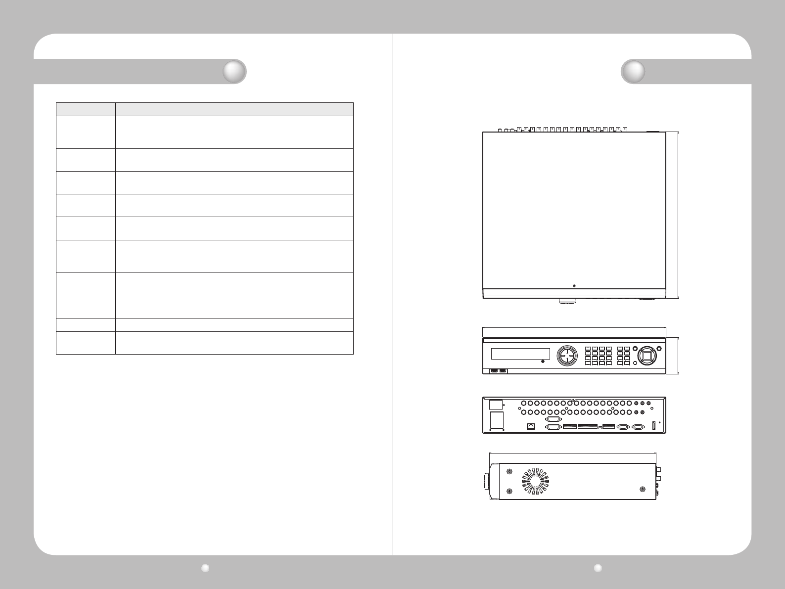
Digital Video Recorder User Guide
120
Digital Video Recorder User Guide
121
Term Denition
Sensitivity
Setting sensitivity of motion detection for a camera determines how much
or little movement is required before an alarm is triggered. A lower setting
triggers more alarms than a higher setting.
Sensor An alarm sensor is available for each camera channel. Sensors are
normally open (N/O), or normally closed (N/C).
Spot monitor A monitor that displays video but that does not provide access to on-
screen display menus.
Sync video
channel The video camera to which recorded audio is associated.
Terminal block A group of connectors on the rear panel of a DVR into which wires are
inserted that control camera position.
Thumbnail
A scene identifier presented by the SVR-1680/1660 after a user searches
for video. Selecting a thumbnail displays the recorded video that starts
with the thumbnail frame.
Tilt To reposition a camera up or down, usually achieved with a computer
mouse or keyboard joystick control.
USB Universal Serial Bus. A standard serial bus used to connect external
devices such as a flash drive or hard disk drive to the SVR-1680/1660.
VGA Video Graphics Array. An analog computer video standard.
Zoom To enlarge or reduce, on a continuously variable basis, the size of a
televised image primarily by varying lens focal length.
Appendix E. Glossary
40588
445
405
Dimension

Digital Video Recorder User Guide
122
Digital Video Recorder User Guide
123
MEMO MEMO

Digital Video Recorder User Guide
124
Digital Video Recorder User Guide
125
MEMO MEMO

Digital Video Recorder User Guide
126
Digital Video Recorder User Guide
127
MEMO MEMO

P/No. : Z6806-1079-01A
VAN 09.10
www.samsungtechwin.com
www.samsungcctv.com
www.samsungipolis.com
• SAMSUNG TECHWIN CO., LTD.
145-3, Sangdaewon 1-dong, Jungwon-gu, Seongnam-si Gyeonggi-do, Korea, 462-703
TEL : +82-31-740-8151~8 FAX : +82-31-740-8145
• SAMSUNG TECHWIN EUROPE CO., LTD.
Samsung House, 1000 Hillswood Drive, Hillswood Business
Park Chertsey, Surrey, UNITED KINGDOM KT16 OPS
TEL : +44-1932-45-5300 FAX : +44-1932-45-5325
• SAMSUNG TECHWIN AMERICA Inc.
1480 Charles Willard St, Carson, CA 90746, UNITED STATES
Tol Free : +1-877-213-1222 FAX : +1-310-632-2195
www.samsungcctvusa.com
SALES NETWORK
