Samsung Srp 275 Receipt Printer Srp275Apg Users Manual KN02 00009E USER'S_20050412
SRP275APG to the manual a58ba269-813a-467a-9cfd-4c00db693e0c
2015-01-23
: Samsung Samsung-Samsung-Srp-275-Receipt-Printer-Srp275Apg-Users-Manual-281657 samsung-samsung-srp-275-receipt-printer-srp275apg-users-manual-281657 samsung pdf
Open the PDF directly: View PDF ![]() .
.
Page Count: 100
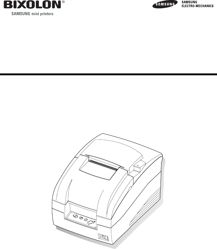
USER’S MANUAL
SRP-275
IMPACT PRINTER
All specifications are subjected to change without notice
www.samsungminiprinters.com

SRP-275
All rights reserved. No part of this publication may reproduced, stored in a retrieval, or transmitted in any
form or by any means, electronic, mechanical, photocopying, recording, or otherwise, without the prior
written permission of SAMSUNG ELECTRO-MECHANICS.
No patent liability is assumed with respect to the use of the information contained herein. While every
precaution has been taken in the preparation of this book, SAMSUNG ELECTRO-MECHANICS assumed no
responsibility for errors or omissions. Neither is any liability assumed for damages resulting from the use of
the information contained herein.
Neither SAMSUNG ELECTRO-MECHANICS nor its affiliates shall be liable to the purchaser of this product
or third parties for damages, losses, costs, or expenses incurred by purchaser or third parties as a result of :
accident, misuse, or abuse of this product or unauthorized modifications, repairs, or alterations to this
product, or (excluding the U.S.) failure to strictly comply with SAMSUNG ELECTRO-MECHANICS s
operating and maintenance instructions.
SAMSUNG ELECTRO-MECHANICS shall not be liable against any damages or problems arising from the
use of any options or ant consumable products other than those designated as Original Samsung products
or Samsung Approved products by SAMSUNG ELECTRO-MECHANICS.
------------------------------------------------------------------------------------------------------------------------------------------------
Notice
The contents of this manual are subject to change without notice.
Copyright© 2004 SAMSUNG ELECTRO-MECHANICS CO., LTD
------------------------------------------------------------------------------------------------------------------------------------------------
EMC and Safety standards Applied
Product Name : SRP-275
The following standards are applied only to the printers that are so labeled.
Europe :
CE marking, TUV/GS : EN60950-1; 2001
North America : EMI : FCC Class A
Safety standards : UL / C-UL : UL60950-1
National : CB-scheme : IEC 60950-1: 2001
------------------------------------------------------------------------------------------------------------------------------------------------
WARNING
The connection of a non-shielded printer interface cable to this printer will invalidate the EMC standards of
this device. You are cautioned that changes or modifications not expressly approved by the party
responsible for compliance could void your authority to operate the equipment.
------------------------------------------------------------------------------------------------------------------------------------------------
CE Marking
The printer conforms to the following Directive and Norms
EMC Directive 89/336/EEC EN55022 Class A : 1998+A1 : 2000
EN55024 : 1998:+A1 : 2001
EN61000-3-2 : 2000
EN61000-3-3 : 1995+A1 : 2001
Low Voltage Directive 73/23/EEC Safety : EN60950-1 : 2001
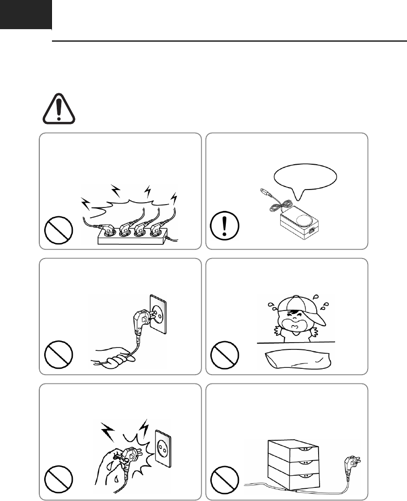
Safety precautions
▌In using the present appliance, please keep the following safety regulations in
order to prevent any hazard or material damage.
WARNING
Violating following instructions can cause serious injury or death.
Do not bend the cable by force or leave it under any
heavy object.
• A damaged cable can cause a fire.
Do not plug in or unplug with your hands wet.
• You can be electrocuted.
Keep the plastic bag out of children’s reach.
• If not, a child may put the bag on his head.
Do not pull the cable to unplug.
• This can damage the cable, which is the origin of a fire or a
breakdown of the printer.
You must use only the supplied adapter.
• It is dangerous to use other adapters.
Do not plug several products in one multi-outlet.
• This can provoke over-heating and a fire.
• If the plug is wet or dirty, dry or wipe it before usage.
• If the plug does not fit perfectly with the outlet, do not plug in.
• Be sure to use only standardized multi-outlets.
PROHIBIT
PROHIBIT PROHIBIT
PROHIBIT PROHIBIT
ONLY SUPPLIED ADAPTER
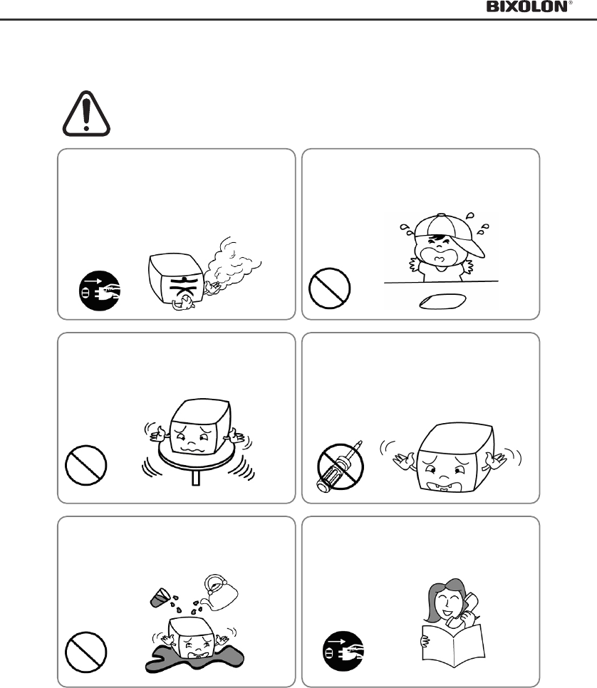
WARNING
Violating following instructions can cause serious injury or death.
Do not use the printer when it is out of order. This
can cause a fire or an electrocution.
• Switch off and unplug the printer before calling your dealer.
Do not let water or other foreign objects in the
printer.
• If this happened, switch off and unplug the printer before
calling your dealer.
Use only approved accessories and do not try to
disassemble, repair or remodel it for yourself.
• Call your dealer when you need these services.
• Do not touch the blade of auto cutter.
Install the printer on the stable surface.
• If the printer falls down, it can be broken and you can hurt
yourself.
Keep the desiccant out of children’s reach.
• If not, they may eat it.
If you observe a strange smoke, odor or noise from
the printer, unplug it before taking following
measures.
• Switch off the printer and unplug the set from the mains.
• After the disappearance of the smoke, call your dealer to
repair it.
TO UNPLUG
PROHIBIT
DISASSEMBLING
PROHIBITED
PROHIBIT
PROHIBIT
TO UNPLUG
PRINTER
PRINTER
PRINTER
PRINTER
DEALER
PRINTER

Table of contents
Chapter 1 Setting up the printer
1.1 Unpacking···················································································································· 1-1
1.2 Choosing a place for the printer ················································································· 1-1
1.3 Connecting the cables································································································· 1-2
1.3.1 Connecting the AC adaptor ············································································ 1-2
1.3.2 Connecting the interface cable and drawer kick-out cable···························· 1-2
1.4 Installing the ribbon cassette ······················································································ 1-3
1.5 Installing the paper roll ································································································ 1-4
1.6 Changing the paper width ··························································································· 1-5
1.7 Installing the wall mount (Option) ··············································································· 1-6
1.8 Using the operation panel ··························································································· 1-7
1.9 Self test························································································································ 1-8
Chapter 2 Troubleshooting
2.1 ERROR LED blinking pattern ····················································································· 2-1
2.2 The printer does not start printing··············································································· 2-2
2.3 The printer stops printing ···························································································· 2-3
2.4 You want to check the operation of the printer by itself ············································· 2-3
2.5 Printing is poor ············································································································ 2-4
2.6 You want to check a software program ······································································ 2-4
Chapter 3 Setting the switches
3.1 Setting the DIP Switch ································································································ 3-1
3.1.1 DIP Switch setting for Epson(ESC/POS) mode············································· 3-1
3.1.2 DIP Switch setting for Citizen(iDP 3550) mode ············································· 3-2
3.1.3 DIP Switch setting for Star(SP500) mode······················································ 3-3
3.1.4 Changing the DIP Switch setting···································································· 3-4
3.2 Setting the Memory Switches ····················································································· 3-5
3.2.1 Memory Switch setting for Epson(ESC/POS) mode ····································· 3-5
3.2.2 Memory Switch setting for Star mode ···························································· 3-9
Chapter 4 Control commands list
4.1 Command notation ······································································································ 4-1
4.2 Explanation of term ····································································································· 4-1
4.3 Exception processing ·································································································· 4-2
4.4 Commands for SRP-275 series ·················································································· 4-3
4.4.1 Commands list for EPSON mode (TM-U220)················································ 4-3
4.4.2 Command description for EPSON mode (TM-U220) ···································· 4-4
4.4.3 Commands list for STAR mode (SP500) ····················································· 4-28
4.4.4 Commands list for CITIZEN mode (iDP3550/3551) ···································· 4-30
Chapter 5 Reference information
5.1 Printing specification ··································································································· 5-1
5.2 Paper specifications ···································································································· 5-1
5.3 Ribbon cassette specification ····················································································· 5-1
5.4 Electrical characteristics ····························································································· 5-2

5.5 Reliability ····················································································································· 5-2
5.6 Environment conditions······························································································· 5-2
5.7 Environment conditions······························································································· 5-3
5.8 Opntional features ······································································································· 5-3
Appendix A Code table
A.1 Page 0 (PC 437 : USA, Standard Europe(International Character Set : USA)) ·······A-1
A.2 Page 1 (Katakana)······································································································A-2
A.3 Page 2 (PC850 : Multilingual)·····················································································A-3
A.4 Page 3 (PC860 : Portuguese) ····················································································A-4
A.5 Page 4 (PC863 : Canadian-French)···········································································A-5
A.6 Page 5 (PC865 : Nordic) ····························································································A-6
A.7 Page 16 (WPC1252 : Latin1) ·····················································································A-7
A.8 Page 17 (PC866 : Russian)························································································A-8
A.9 Page 18 (PC852 : Latin2) ···························································································A-9
A.10 Page 19 (PC858 : Euro) ·························································································A-10
A.11 Page 21 (PC862 : Israel) ························································································ A-11
A.12 Page 22 (PC864 : Arabic)·······················································································A-12
A.13 Page 23 (Thai character code 42)··········································································A-13
A.14 Page 24 (WPC1253 : Greek) ·················································································A-14
A.15 Page 25 (WPC1254 : Turkish)················································································A-15
A.16 Page 26 (WPC1257 : Baltic) ··················································································A-16
A.17 Page 27 (Farsi) ·······································································································A-17
A.18 Page 28 (WPC1251 : Russian) ··············································································A-18
A.19 Page 29 (PC737 : Greek) ·······················································································A-19
A.20 Page 30 (PC775 : Baltic)························································································A-20
A.21 Page 31 (Thai character code 16)··········································································A-21
A.22 Page 32 (OldCode : Israel)·····················································································A-22
A.23 Page 33 (WPC 1255 : Israel) ·················································································A-23
A.24 Page 34 (Thai character code 11)··········································································A-24
A.25 Page 35 (Thai character code 18)··········································································A-25
A.26 International character code table··········································································A-26
Appendix B Connectors
B.1 RS-232C Serial I/F······································································································B-1
B.1.1 RS-232C Serial I/F cable connection ···························································B-1
B.1.2 RS-232C Serial I/F signal descriptions ························································B-1
B.2 IEEE 1284 Parallel I/F ······························································································B-2
B.2.1
IEEE 1284 Parallel I/F signal specification (Compatibility / Nibble / Byte mode)
······B-2
B.3 USB I/F ······················································································································B-3
B.3.1 USB I/F signal description ············································································B-3
B.4 Drawer kick-out ·········································································································B-3
B.4.1 Drawer kick-out connection ··········································································B-3
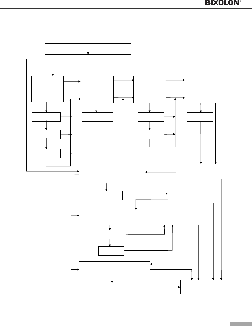
Introduction
▌The SRP-275 is a high-quality impact printer.
▌This one-station printer has the following features.
• Compact design and light-weight.
• High-speed printing using logic-seeking (5.1LPS).
• Easy to use : Easy paper loading.
• High reliability and long life due to the use of stepping motors for head carriage return
and paper feeding.
• Two color printing (red/black) available.
• Various formats are possible because the paper feeding pitch is selectable.
• High general control utility based on the ESC/POS(TM) standard.
• The head can be driven due to the internal drawer interface.
• Character font (7ⅹ9, 9ⅹ9) is selectable.
• The auto cutter uses a circular method with a high-quality blade and a long life
(Approximately 1,000,000 cuts).
• Paper near end Switch is standard.
• A internal AC adaptor.
NOTES
Please be sure to read the instructions in this manual carefully before using your new printer.
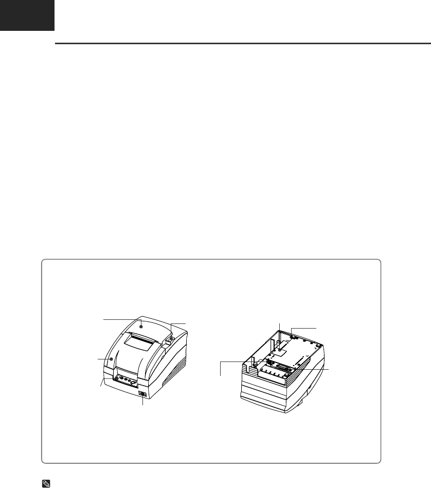
• Front view • Rear view
Rear cover
Front cover
Control panel
Power switch
Open button
Drawer kick-out
connect
Interface
connector
Power connect
DIP Switch cover
CHAPTER 1
Setting up the printer
1-1
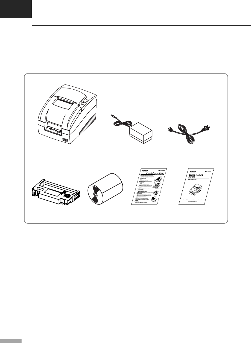
▌1.1 Unpacking
Your printer box should include the items shown in the illustration below.
If any items are damaged or missing, please contact your dealer.
▌1.2 Choosing a place for the printer
• Avoid locations that are subject to direct sunlight or excessive heat.
• Avoid using or storing the printer in a place subject to excessive temperature or moisture.
• Do not use or store the printer in a dirty location.
• When setting up the printer, choose a stable, horizontal location.
• Intense vibration or shock may damage the printer.
• Ensure the printer has enough space to be used easily.
SRP-275A, C AC adaptor Power cord
Ribbon cassette Paper roll Quick reference guide User’s manual
1-2
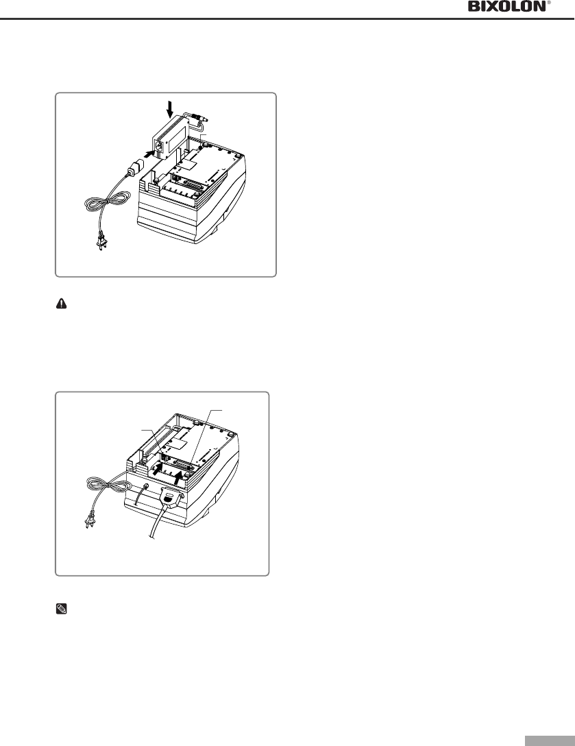
▌1.3 Connecting the cables
▌1.3.1 Connecting the AC adaptor
CAUTION
Before connecting the printer to the power supply, make sure that the voltage and power specifications
match the printer’s requirements. Using an incorrect power supply can cause serious damage to the
printer.
▌1.3.2 Connecting the interface cable and drawer kick-out cable
NOTES
Connect the printer to the host ECR (host computer) though an interface cable matching the specification
of the printer and the host ECR (host computer). Be sure to use a drawer that matches the printer’s
specification.
Depending on the interface your system uses, either connect the serial, parallel, USB or Ethernet
communication cable to the appropriate connector on the back of the printer. Cables are provided by
your dealer or system installer.
• Connect the AC adapter according to the
following procedure.
1) Make sure the printer is turned off.
2) Before inserting the AC adaptor, connect the
power cord.
3) Insert the AC adaptor as shown.
4) Plug the AC adapter cable into the printer’s
power connector.
5) Plug the power cord into the outlet, and turn on
the power.
AC adaptor
Power connector
Power cord
Drawer kick-out connector
Interface
connector
Serial/ Parallel/ USB/ Ethernet
Interface cable
Drawer kick-out
cable
• Connect the cables according to the
following procedure.
1) Turn off printer and the host ECR (host
computer).
2) Plug the interface cable into the interface
connector on the printer then fasten the screw
on both sides of the connector.
3) Plug the drawer kick-out cable into the drawer
kick-out connector on the printer.
(When removing the drawer kick-out cable,
press on the connector’s clip while pulling out.)
CHAPTER 1
Setting up the printer
1-3
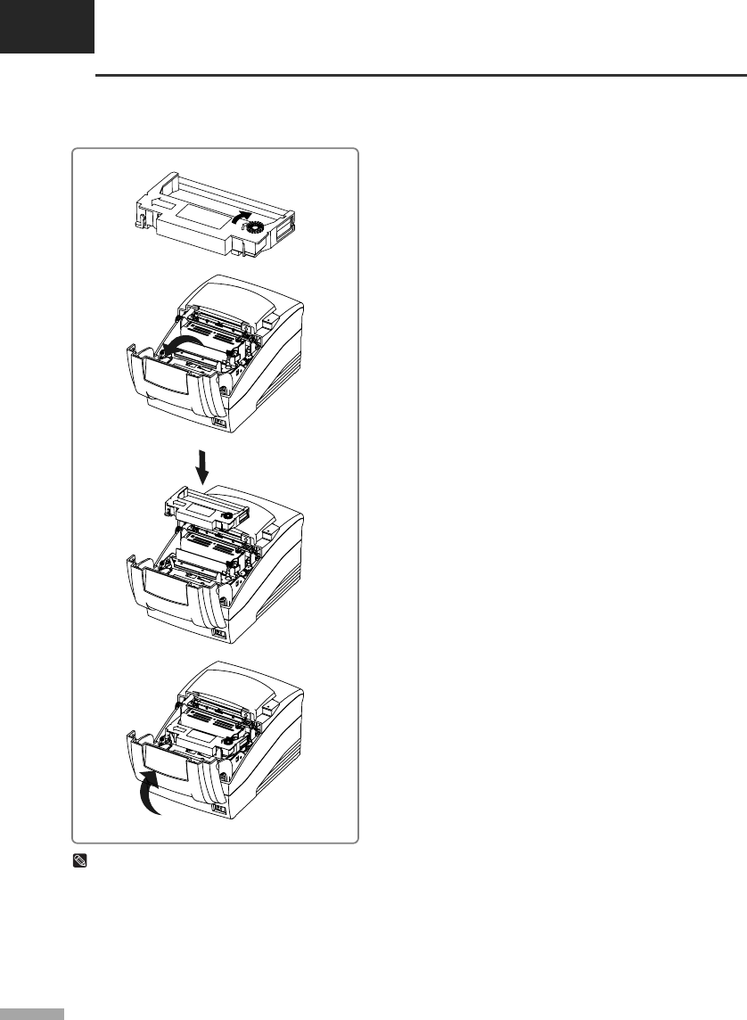
▌1.4 Installing the ribbon cassette
NOTES
Malfunctions and other problems may arise if other than specified ribbon cassettes are used in the printer.
The Warranty may be void if other than specified ribbon cassettes are used. Contact your dealer or place
of purchase for more information about proper ribbon cassettes.
1) Before inserting the ribbon cassette, turn the
knob clockwise to prevent twisting the ribbon.
2) Open the front cover of printer.
3) Take out the old ribbon cassette if there is one.
4) Insert the new ribbon cassette as shown and
pay particular attention to the placement of the
ribbon behind the Printer Head.
5) During inserting the ribbon cassette, turn the
knob clockwise again to make sure the ribbon
moves freely in the cassette.
6) Close front cover of printer.
1-4
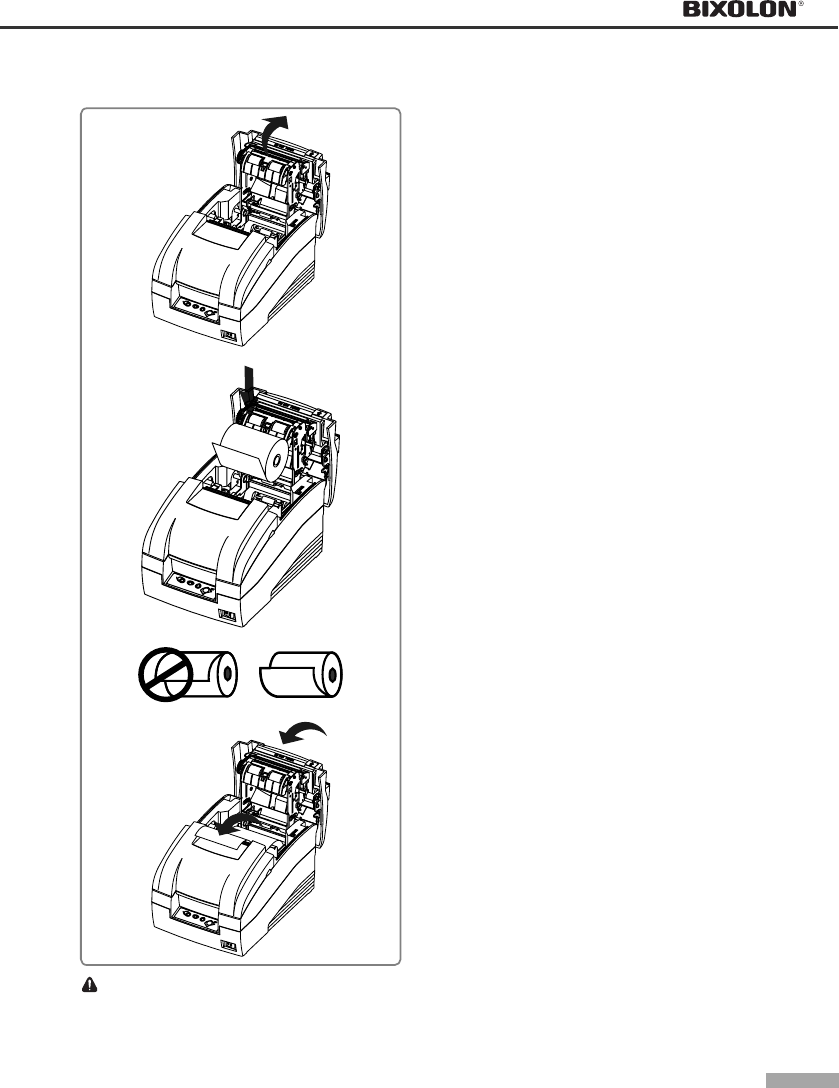
▌1.5 Installing the paper roll
CAUTION
Do not touch the auto cutter blade when you open rear cover.
1) To prevent data loss, make sure that the printer
is not receiving data.
2) Open the rear cover by pushing the open
button.
3) Remove the used paper roll core if there is one.
4) Insert the paper roll as shown.
5) Be sure to note the correct direction that the
paper should come off the paper roll.
6) Pull out small amount of paper as shown. Then
close the cover and tear off the extra paper by
pulling it toward the front of the printer.
CHAPTER 1
Setting up the printer
1-5
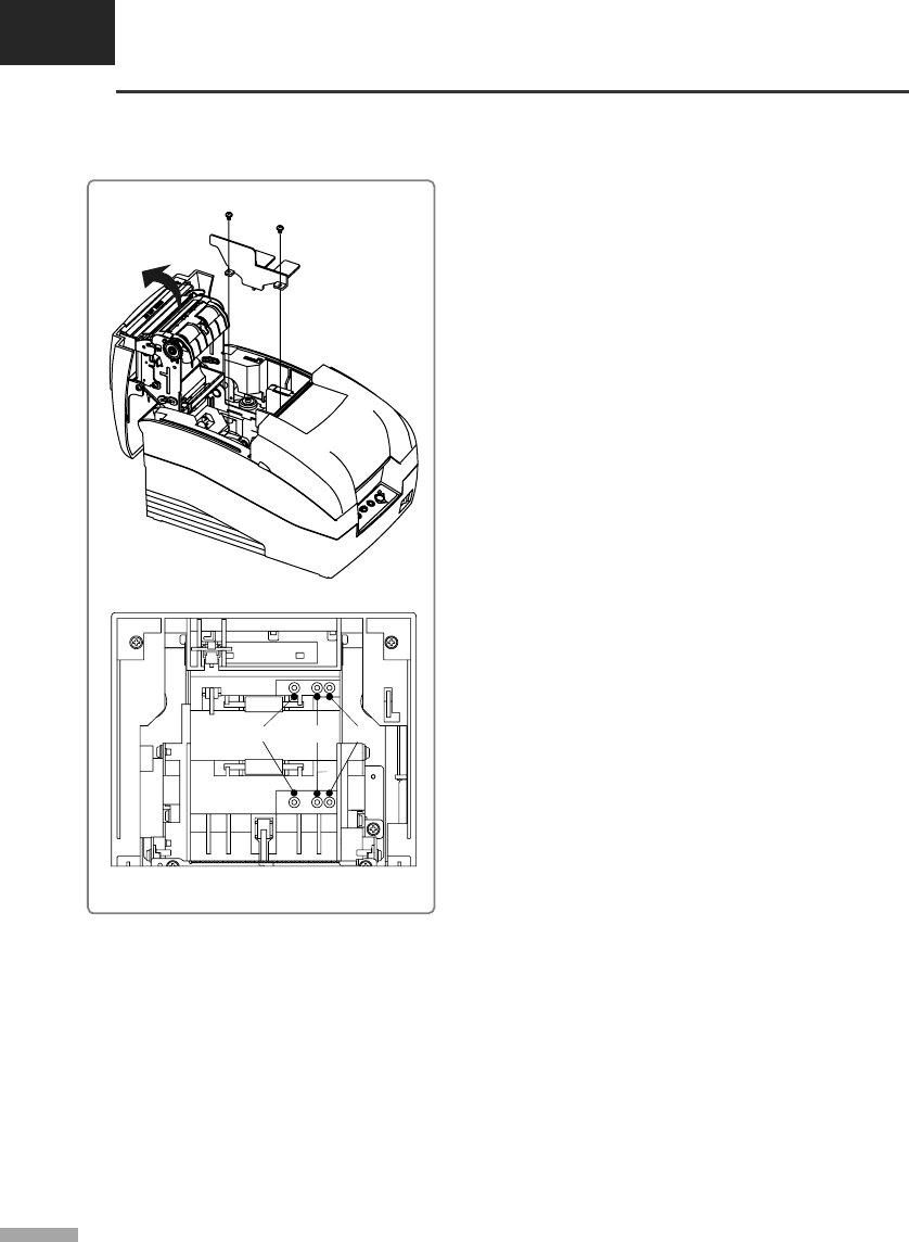
▌1.6 Changing the paper width
Screw(3x6)(2pieces)
Frame paper control
57.5mm 69.5mm 76mm(default)
1) Open the rear cover.
2) Remove the frame paper control by loosing the
two screws(3×6).
3) Reattach the frame paper control in you want.
(Insert and tighten two screws(3×6) to reattach.)
4) Close the rear cover.
5) Change the Memory Switch setting for changing
paper roll width. (See the instructions "Setting
the Memory Switches"(3.1) in Chapter 3.)
1-6
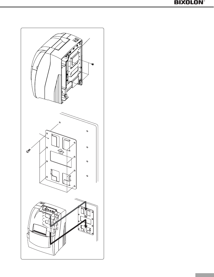
▌1.7 Installing the wall mount (Option)
Bracket hanger
Screw(3x5)
(4pieces)
Bracket mount
Screw(4x10)
(8pieces)
1) Turn the Set over and attach the Bracket
hanger to the Frame base then tighten four
screws.
2) Attach the Bracket mount to the wall firmly with
the eight screws. Be sure that the Bracket
attached properly to match the direction of
arrow as shown. And the Bracket mount should
be always fixed vertically.
3) Insert the Bracket hanger of Set to the Bracket
mount as shown.
CHAPTER 1
Setting up the printer
1-7
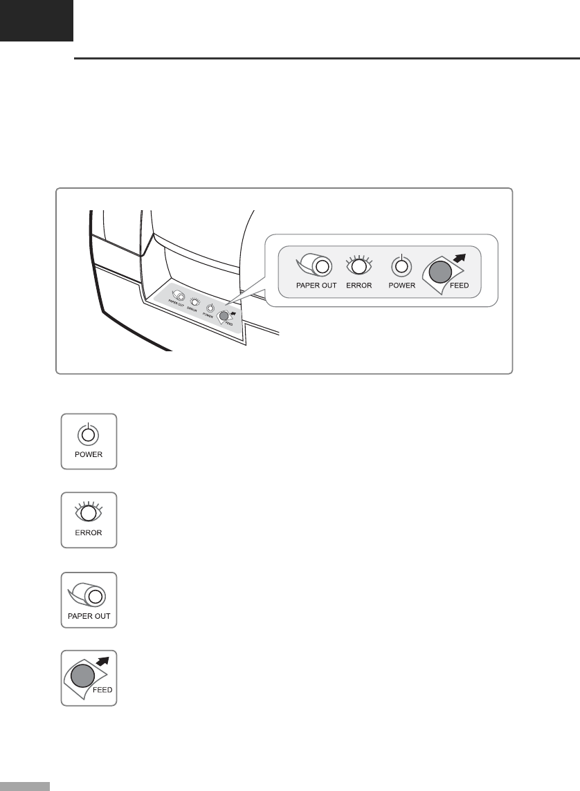
▌1.8 Using the operation panel
Most of the functions of this printer are governed by software, but you can monitor the printer s status by
looking at the lights on the control panel and for some procedures you will use the buttons.
• Control panel
- POWER LED (Green Color)
This indicator light is on when the power is turned on. It blinks when the printer is in the self
test printing standby state. Always wait until this indicator light stops blinking before you
start using the printer and before you turn it off.
- ERROR LED (Red Color)
When this indicator light is on (but not blinking), it means that the printer is out of paper or
almost out of paper or the printer covers are open. When this light blinking, there is an
error. (See "ERROR LED blinking pattern" (2.1) in Chapter 2.) If you see this light blinking,
turn off the printer for a few seconds and then turn it back on. If the light is still blinking, call
your supervisor or a service person.
- PAPER OUT LED (Red Color)
When this indicator light is on, it means that the paper near end. Replace the new paper
roll. When ERROR and PAPER OUT indicator lights are on it means paper end. Install the
paper roll.(See "Installing paper roll"(1.5)in Chapter 1.)
- FEED button
Use this button to feed paper or to start self test and for hexadecimal dump mode.
(See the instructions "Self test" (1.7) in this chapter for self test.)
(See the instructions "Hexadecimal dump" (2.6) in Chapter 2 for hexadecimal dump mode.)

1-8
▌1.9 Self test
The self test let you know if your printer is operating properly. It checks the printing quality, ROM version,
DIP Switch settings, memory switch settings and statistic data.
The test is independent of any other equipment or software, so it is a good idea to run it when you first set
up the printer or if you have any trouble. If the self test works correctly, the problem is in the other equipment
or the software, not the printer.
• Running the self test
1) Make sure the printer is turned off and the printer cover is closed properly.
2) While holding down the FEED button, turn on the printer and continue to hold until the paper begins to
feed. The self test prints the printer DIP Switch settings and memory switch settings. And cuts the paper
and pauses. (The power light blinks.)
3) Press the FEED button to continue printing the statistic data.
4) Press the FEED button to continue printing the rolling ASCII pattern.
5) The self test mode terminates after printing the rolling ASCII pattern automatically.
CHAPTER 2
Troubleshooting
2-1
This chapter gives solutions to some printer problems you may have.
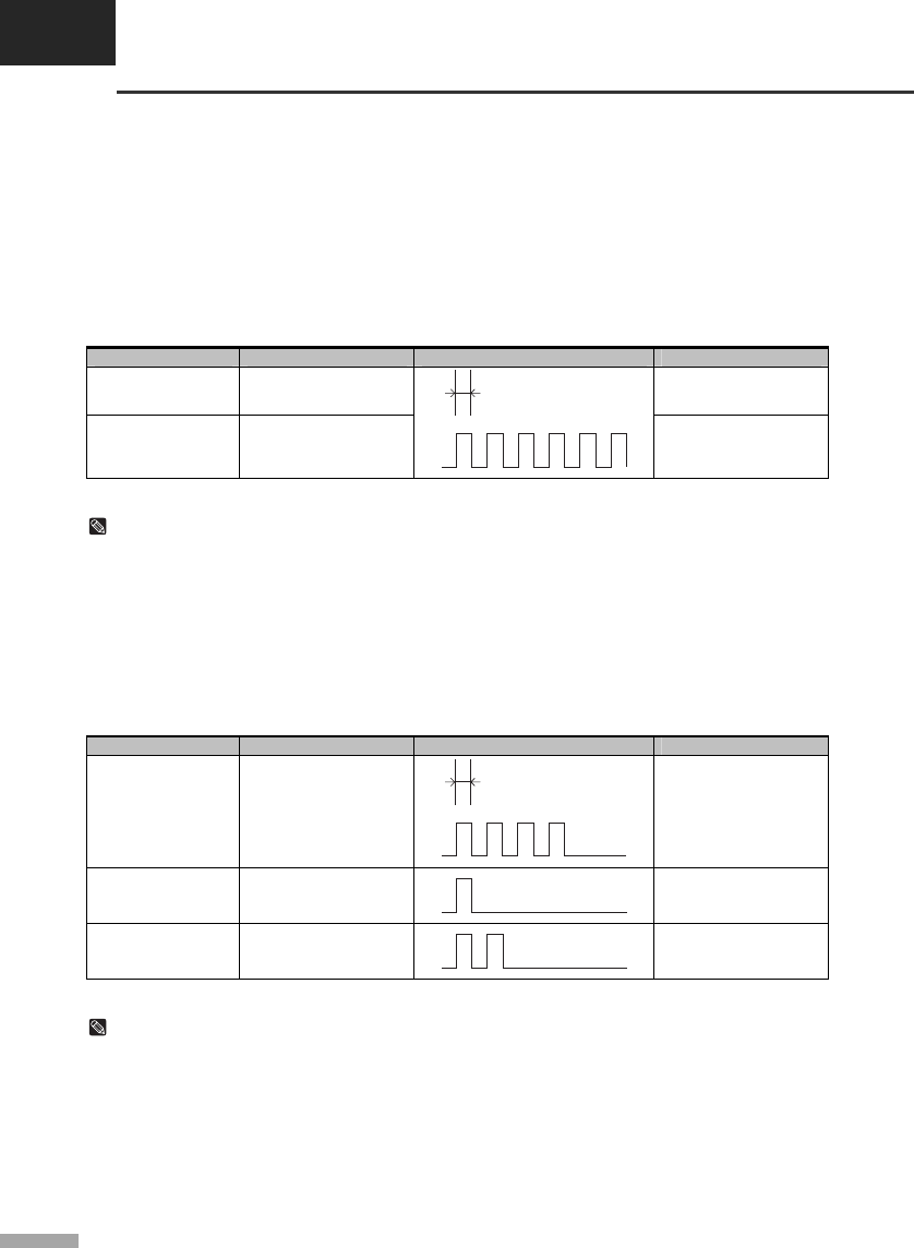
▌2.1 ERROR LED blinking pattern
The printer stops all printer operations for the selected paper section, goes off line, and the ERROR LED
blinks when an error is detected.
• Errors that automatically recover
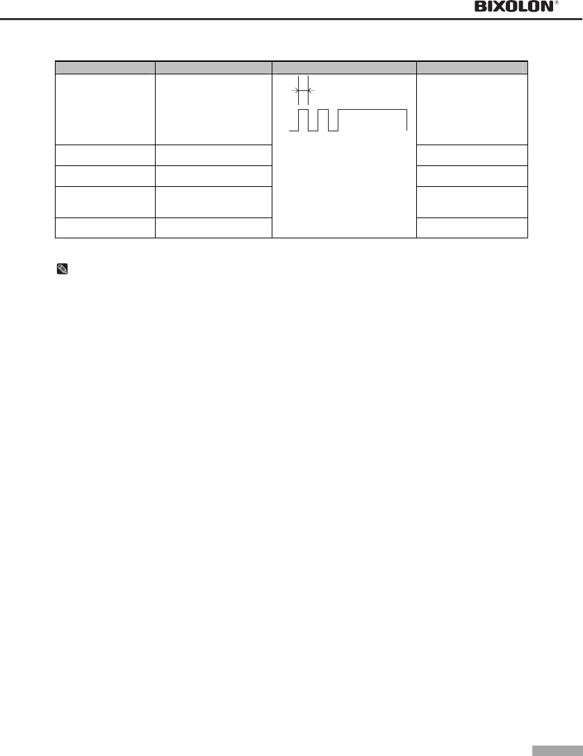
Error Description ERROR LED blinking pattern Recovery
Rear cover open error
(When recoverable
Error is selected)(*1)
The rear cover is opened
when printing
Recovers automatically
when the rear cover is
closed.
Print head
temperature error(*2)
The temperature of the
print head is extremely
high.
200ms
Recovers automatically
when the print head
cools.
NOTES
(*1) These conditions are selected by MSW8-5, 8-8. When MSW8-5 (mapping of the cover open status)
is off, the error hasn’t occurred but there is a “paper end error” instead. If MSW8-8 is off, this error
is handled as an automatically recoverable error.
(*2) Print head temperature error is not abnormal.
• Recoverable errors
When a recoverable error occurs, after the cause of the error is removed, the printer can recover from the
error by receiving an error recovery command without turning off the power.
Error Description ERROR LED blinking pattern Recovery
Rear cover open error
(*1)
The rear cover is opened
when printing.
200ms
Recovers automatically
when the rear cover is
closed.
Auto cutter error
(Type C only)
The auto cutter does not
work correctly.
Recovers by error
recovery command.
Home position
detection error (This
is “Mechanical error”)
The home position
cannot be detected due
to a paper jam.
Recovers by error
recovery command.
NOTES
(*1) These conditions are selected by MSW8-5, 8-8. When MSW8-5 (mapping of the cover open status)
is off, the error hasn’t occurred but there is a “paper end error” instead. If MSW8-8 is off, this error
is handled as an automatically recoverable error.
2-2
• Errors that are impossible to recover
Error Description ERROR LED blinking pattern Recovery
R/W error in memory
or gate array
After R/W checking, the
printer does not work
correctly.
Writing to, reading out, or
erasing the NV memory for
image scanning results
does not work correctly.
Recovers automatically
when the rear cover is
closed.
High voltage error The power supply voltage
is extremely high. Impossible to recover.
Low voltage error The power supply voltage
is extremely low. Impossible to recover.
CPU execution error
The CPU executes an
incorrect address or I/F
board is not connected.
Impossible to recover.
Print head temperature
detection circuit error.
There is an abnormality is
the print head temperature.
200ms
Impossible to recover.
NOTES
If you see this light blinking, turn off the printer for a few seconds and then turn it back on.
If the light is still blinking, call your supervisor or a service person.
▌2.2 The printer does not start printing
• Are any of the operation panel lights on, If no operation panel lights are on, check the following:
- Make sure that the printer is turned on.
- Make sure that the power supply cable is correctly plugged into the printer and to the power outlet.
• If any of the lights are on, please check the following:
- If the POWER LED is blinking, the printer is not ready yet.
Wait until the light quits blinking and the printer is ready to use.
- If the ERROR LED is on (but not blinking), the printer is off line. Check to see that the covers are closed
and check the paper state. See "Installing paper roll" (1.5) in Chapter 1 for instructions on installing or
replacing the paper roll.
- If the ERROR LED is blinking, there is an error. In this case, turn off the printer for a few seconds and
then turn it back on. If the light is still blinking, call your supervisor or service person.
- If the PAPER OUT LED is on, check the paper roll in the printer. See "Installing paper roll" (1.5) in
Chapter 1 for instruction on installing the paper roll.

CHAPTER 2
Troubleshooting
2-3
▌2.3 The printer stops printing
• If the ERROR LED is on (but not blinking), the printer is off line. Check to see that the covers are closed
and check the paper state. See "Installing paper roll"(1.5) in Chapter 1 for instructions on installing or
replacing the paper roll.
• If the ERROR LED is blinking, there is an error. In this case, turn off the printer for a few seconds and then
turn it back on. If the LED is still blinking, call your supervisor or a service person.
• Turn off the printer and check for a paper jam. To clear paper jam, follow the steps below:
1) Turn off the printer and open the rear cover of the printer.
2) Remove the jammed paper and reload the paper roll as described in Chapter 1.
3) Close the rear cover.
4) Turn on the printer.
▌2.4 You want to check the operation of the printer by itself
• Self test
Try to run the self test to check that the printer works properly. See the self test instructions in Chapter 1
to run the self test. If the self test does not work, contact your supervisor or a service person.
If the self test works properly, check the following:
1) Check the connection at both ends of the interface cable between the printer and the computer. Also
make sure that this cable meets the specifications for both the printer and the computer.
2) The data transmission settings may be different between the printer and computer. Make sure that the
printer’s DIP Switch settings for data transmission are the same as the computer’s. You can see the
printer’s interface settings on your self test printout.
NOTES
If the printer still does not print, contact your dealer or a qualified service person.
2-4
▌2.5 Printing is poor
Check the state of ribbon cassette. If the ribbon cassette life ends, replace the ribbon cassette as
described in Chapter 1.
NOTES
If the printer is still poor, contact your dealer or a qualified service person.
▌2.6 You want to check a software program
• Hexadecimal dump
This feature allows experienced users to see exactly what data is coming to the printer.
This can be useful in finding software problems. When you turn on the hexadecimal dump function, the
printer prints all commands and other data in hexadecimal format along with a guide section to help you
find specific commands.
• To use the hexadecimal dump feature, follow these steps:
1) After you make sure that the printer is off, open the rear cover of the printer.
2) Hold down the FEED button while you turn on the printer.
3) Close the rear cover.
4) Run any software program that sends data to the printer. The printer prints "Hexadecimal dump" and
then all the codes are received in a two column format. The first column contains the hexadecimal
codes and the second column gives the ASCII characters that correspond to the codes.
Hexadecimal Dump
To terminate hexadecimal dump
Press FEED button three times
1B 21 00 1B 26 02 40 40 . ! . . & . @ @
1B 25 01 1B 63 34 00 1B . % . . c 4 . .
41 42 43 44 45 46 47 48 A B C D E F G H
<Online Hex Dump Completed>
(A period(.) is printed for each code that has no ASCII equivalent.)
5) When the printing finishes, turn off the printer.
CHAPTER 3
Setting the switches
3-1
▌3.1 Setting the DIP Switch
Although the factory settings are best for almost all users, if you have special requirements, you can change
the DIP Switch. Your printer has two sets of DIP Switches. The functions of the switches are shown in the
following table.
▌3.1.1 DIP Switch setting for Epson(ESC/POS) mode
• DIP Switch 1
Switch Function ON OFF Default
1-1
1-2 Emulation Selection (*1) Refer to the following table OFF
1-3 Auto cutter Enable Disable OFF
1-4 BUSY condition Receive buffer full Receive buffer full
or Offline OFF
1-5 Serial interface selection Memory Switch DIP Switch OFF
1-6 Print NV bit image #1 after cutting Enable Disable OFF
1-7 Near end switch Enable Disable OFF
1-8 Print column 42/35 40/33 OFF
• DIP Switch 2 (RS232C serial interface model)
Switch Function ON OFF Default
2-1 Data receive error Ignore Print “?” OFF
2-2 Reserved OFF
2-3 Hand shaking XON/XOFF DTR/DSR OFF
2-4 Word length 7 bits 8 bits OFF
2-5 Parity check Enable Disable OFF
2-6 Parity selection EVEN ODD OFF
2-7 OFF
2-8 Baud rate selection (*2) Refer to the following table OFF
• DIP Switch 2 (Parallel interface model)
Switch Function ON OFF Default
2-1 Auto Line Feed Enable Disable OFF
2-2~8 Undefined OFF
NOTES
(*1) Emulation Selection (DSW 1-1 and 1-2)
Emulation 1-1 1-2
EPSON OFF OFF
STAR OFF ON
CITIZEN ON OFF
EPSON-KP ON ON
- EPSON-KP(EPSON Kitchen Printer mode) : A alarm is generated by printer after auto cutting and in paper end error.
(*2) Baud rate selection (Transmission speed)
Transmission 2-7 2-8
2400 baud ON ON
4800 baud OFF ON
9600 baud OFF OFF
19200 baud ON OFF
3-2
▌3.1.2 DIP Switch setting for Citizen(iDP 3550) mode
• DIP Switch 1
Switch Function ON OFF Default
1-1
1-2 Emulation Selection (*1) Refer to the following table OFF
1-3 Auto cutter Enable Disable OFF
1-4 CBM command CBM2 mode
(iDP3530 system)
CBM1 mode
(iDP3540 system) OFF
1-5
1-6
1-7
International characters (*2) Refer to the following table ON
1-8 CR mode CR CR+LF OFF
• DIP Switch 2 (RS232C serial interface model)
Switch Function ON OFF Default
2-1 Word length 8 bits 7 bits ON
2-2 Parity check Disable Enable ON
2-3 Parity selection ODD EVEN ON
2-4 Hand shaking DTR/DSR XON/XOFF ON
2-5
2-6 Baud rate selection (*3) Refer to the following table OFF
2-7 Near end switch Enable Disable OFF
2-8 Mechanism type Graphic Character OFF
NOTES
(*1) Emulation Selection (DSW 1-1 and 1-2)
Emulation 1-1 1-2
EPSON OFF OFF
STAR OFF ON
CITIZEN ON OFF
EPSON-KP ON ON
- EPSON-KP(EPSON Kitchen Printer mode) : A alarm is generated by printer after auto cutting and in paper end error.
(*2) International Character Selection
No.
Country DSW 1-5 DSW 1-6 DSW 1-7 Code page
U.S.A. ON ON ON Page 0 (PC437 : U.S.A.)
France OFF ON ON
Germany ON OFF ON
U.K. OFF OFF ON
Page 2 (PC850 : Multilingual)
Denmark ON ON OFF
Sweden OFF ON OFF
Page 5 (PC865 : Nordic)
Italy ON OFF OFF Page 2 (PC850 : Multilingual)
Windows Code OFF OFF OFF Windows Code
(*3) Baud rate selection (Transmission speed)
Transmission 2-5 2-6
2400 baud ON ON
4800 baud OFF ON
9600 baud OFF OFF
19200 baud ON OFF
CHAPTER 3
Setting the switches
3-3
▌3.1.3 DIP Switch setting for Star(SP500) mode
• DIP Switch 1
Switch Function ON OFF Default
1-1
1-2 Emulation Selection (*1) Refer to the following table OFF
1-3 Auto cutter Enable Disable OFF
1-4 Black/Red Printing Enable Disable OFF
1-5
1-6
1-7
1-8
Reserved OFF
• DIP Switch 2 (RS232C serial interface model)
Switch Function ON OFF Default
2-1
2-2 Reserved OFF
2-3 Hand shaking XON/XOFF DTR/DSR OFF
2-4 Word length 7 bits 8 bits OFF
2-5 Parity check Enable Disable OFF
2-6 Parity selection EVEN ODD OFF
2-7 OFF
2-8 Baud rate selection (*2) Refer to the following table OFF
NOTES
(*1) Emulation Selection (DSW 1-1 and 1-2)
Emulation 1-1 1-2
EPSON OFF OFF
STAR OFF ON
CITIZEN ON OFF
EPSON-KP ON ON
- EPSON-KP(EPSON Kitchen Printer mode) : A alarm is generated by printer after auto cutting and in paper end error.
(*2) Baud rate selection (Transmission speed)
Transmission 2-7 2-8
2400 baud ON ON
4800 baud OFF ON
9600 baud OFF OFF
19200 baud ON OFF
NOTICE
Change in DIP Switch settings are recognized only when the printer power is turned on or when the
printer is reset by using the interface. If the DIP Switch setting is changed after the printer power is
turned on, the change does not take effect until the printer is turned on again or is reset.
3-4
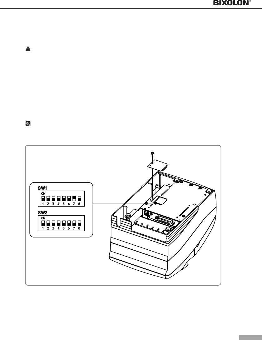
▌3.1.4 Changing the DIP Switch setting
If you need to change settings, follow the steps below to make your changes.
CAUTION
Turn off the printer before removing the DIP Switch cover to prevent an electric short, which can damage
the printer.
1) Make sure the printer is turned off.
2) Remove the screw from the DIP Switch cover.
Then take off the DIP Switch cover, which is shown in the illustration below.
3) Set the switches using a pointed tool, such as tweezers or a small.
4) Replace the DIP Switch cover. Then secure it with the screw.
NOTES
The new settings take effect when you turn on the printer.
CHAPTER 3
Setting the switches
3-5
▌3.2 Setting the Memory Switches
▌3.2.1 Memory Switch setting for Epson(ESC/POS) mode
This printer has “Memory Switch” set which is software switches. Memory Switch set has “MSW 2”, “MSW 8”,
“Customize value”, “Serial communication condition”. “Memory Switch setting utility” can change the Memory
Switch set to ON or OFF as shown in the table below (default: all OFF):
NOTES
The Memory Switch is available to be changed by three methods:
- Memory Switch setting utility
- Memory Switch setup mode (there are limitations on what can be changed)
- Control from ESC/POS command
- Some Memory Switch settings can be changed by the “Memory Switch setting mode”. See “Procedure of
Memory Switch setting”.
Settings of the Memory Switch are stored in the NV memory; therefore, even if the printer is turned off, the
settings are maintained. When you replace a SRP-270 with a SRP-275, you should adjust the MSW 8-5 to
OFF.
• Memory Switch 2
Switch Function On Off
1 Reserved - Fixed to Off
2 Reserved - Fixed to Off
3 Reserved for Chinese selection - Fixed to Off
4~8 Code page selection (*1) Refer to the following table
NOTES
Desired code page can be selected using Memory Switch 2-4~8 by setting as following.
(*1) Code page selection
MSW 2-8 MSW 2-7 MSW 2-6 MSW 2-5 MSW 2-4 Character Table
0 0 0 0 0 Page 0 (PC437 : U.S.A.)
0 0 0 0 1 Page 1 (Katakana)
0 0 0 1 0 Page 2 (PC850 : Multilingual)
0 0 0 1 1 Page 3 (PC860 : Portuguese)
0 0 1 0 0 Page 4 (PC863 : Canadian-French)
0 0 1 0 1 Page 5 (PC865 : Nordic)
0 0 1 1 0 Page 16 (WPC1252 : Latin1)
0 0 1 1 1 Page 17 (PC866 : Russian)
0 1 0 0 0 Page 18 (PC852 : Latin2)
0 1 0 0 1 Page 19 (PC858 : Euro)
0 1 0 1 0 Page 21 (PC862 : Israel)
0 1 0 1 1 Page 22 (PC864 : Arabic)
0 1 1 0 0 Page 23 (Thai character code 42)
0 1 1 0 1 Page 24 (WPC1253 : Greek)
0 1 1 1 0 Page 25 (WPC1254 : Turkish)
0 1 1 1 1 Page 26 (WPC1257 : Baltic)
1 0 0 0 0 Page 27 (Farsi) (*2)
1 0 0 0 1 Page 28 (WPC1251 : Russian) (*2)
1 0 0 1 0 Page 29 (PC737 : Greek) (*2)
1 0 0 1 1 Page 30 (PC775 : Baltic) (*2)
1 0 1 0 0 Page 31 (Thai character code 16)
1 0 1 0 1 Page 32 (OldCode : Israel)
1 0 1 1 0 Page 33 (WPC1255 : Israel)
1 0 1 1 1 Page 34 (Thai character code 11)
1 1 0 0 0 Page 35 (Thai character code 18)
(*2) Only Font B available.
3-6
• Memory Switch 8
Switch Function On Off
1
2
3
4
Reserved - Fixed to Off
5 Selection of the cover open status Cover open Paper end
6 Reserved - Fixed to Off
7 Receive buffer full release Remaining 522 bytes Remaining 640 bytes
8 Printer (Cover open during operation) Errors that can
possibly recover
Errors that
automatically recover
NOTES
MSW 8-5:
When Off is selected, a bit of the “paper end sensor” in each status that is transmitted from the printer is
changed every time the rear cover is open or closed. When On is selected, a bit of the “rear cover open /
close" in each status that is transmitted from the printer is changed every time the rear cover is open or
closed. When you replace a SRP-270 with a SRP-275, you should adjust the MSW 8-5 to Off.
MSW 8-8:
When Off is selected, a bit of the “automatic recoverable error” in each status that is transmitted from
the printer is changed every time the rear cover is open. When On is selected, a bit of the “mechanical
error” in each status that is transmitted from the printer is changed every time the rear cover is open.
The setting of MSW 8-5 and 8-8 can be set by “Memory Switch setup mode”.
• Customize value
Function Selectable value
Paper roll width 57.5 mm / 69.5 mm / 76 mm (default value)
NOTES
These setting can be set by “Memory Switch setup mode.”
• Serial communication
Function Selectable value
2400 bps 4800 bps
baud rate 9600 bps 19200 bps
None Odd
Parity Even -
Handshake DSR/DTR XON/XOFF
Data length 7 bit 8 bit
NOTES
There are two methods, DIP Switch and Memory Switch, to adjust the serial communication conditions.
DIP Switch 1-5 selects which is effective, DIP Switch or Memory Switch.
To enable the “Serial communication“ setting, you have to adjust the “Serial interface selection“ function
of DIP Switch 1-5 to “Memory Switch”.
These settings can be set by “Memory Switch setup mode”.

CHAPTER 3
Setting the switches
3-7
• Memory Switch Setup Mode
The following items are specified in the Memory Switch setup mode:
Basic Serial communication condition (Serial communication)
- Transmission speed
- Parity
- Handshaking
- Data length
Receive buffer full release condition (MSW 8-7)
Paper roll width (Customize value)
Cover open status (MSW 8-5)
NOTES
All new settings will be lost if the power supply is turned off in the Memory Switch setup mode. Be sure to
follow the proper procedure, and turn the power off at the correct time.
Use the following procedure to start the Memory Switch setup mode.
1) Open the rear cover.
2) Turn the power on while pressing the paper FEED button.
3) Press the FEED button twice while POWER, ERROR, and PAPER OUT LEDs are lit.
4) Close the cover. The printer prints the enabled settings of the Memory Switches and instructions.
5) Follow the instructions to process the switch setup.
NOTES
In the Memory Switch setup, the power LED may be flashing.
• Example of Memory Switch setup sheet
Memory S/W Setup
You can choose desired item using
YES or NO as following
YES: Keep pressing FEED button
Until printing starts
NO : Press & release it swiftly
Serial interface setting
Do you want to change
Serial interface condition?
Buffer full release condition
Current condition: 640 bytes left
Do you want to change
Buffer full release condition?
Paper width
Current paper width: 76.0 mm
Do you want to change
paper width?
Cover open status
Current status: Paper out
Do you want to change
cover open status?
3-8
• Procedure of Memory Switch setting
①Resetting Basic Serial Interface?
Baud rate
Current
setting:
9600 bps
19200bps
4800bps
2400bps
Handshake
Current
setting:
DSR/DTR
XON/XOFF
Parity
Current
setting:
Non
Even
Odd
Data bit
Current
setting:
8 bits
7 bits
NO
NO
NO
NO
NO
YES
YES
YES
YES
NO NO
YES YES
NO
NO
NO
YES
YES
NO
②Resetting Buffer full release
condition?
Current setting: 640 bytes
69.5 mm
522 bytes
NO
③Resetting Paper width?
Current setting: 76 mm
57mm
④Resetting Cover open status?
Current setting: Paper out
Cover open
Finishing Memory
S/W Setting Mode?
YES
Memory S/W Setting
Completed
NO
YES YES
YES
NO
YES
YES
NO
NO
YES
YES
YES
NO
NO
NO
YES
YES
Finishing Memory
S/W Setting Mode?
Finishing Memory
S/W Setting Mode?
NO YES
YES
Entering Memory Switch Setting Mode
CHAPTER 3
Setting the switches
3-9
▌3.2.2 Memory Switch setting for Star mode
• Settings
Memory Switches are from MSW 0 to MSW 8. They are stored in non-volatile memory (flash memory). To
change the settings, send the following commands from the host.
[Name] Set Memory Switch
[Code] ASCII ESC GS # m N n1 n2 n3 n4 LF NUL
Hexadecimal 1B 1D 23 m N n1 n2 n3 n4 0A 00
Decimal 27 29 35 m N n1 n2 n3 n4 10 0
[Defined Region] m = "W", "T", ",", "+", "-", "@"
"0" ≤ N,n1,n2,n3,n4 ≤ "9",
"A" ≤ N,n1,n2,n3,n4 ≤ "F"
[Function] Sends command to write after defining Memory Switch using the definition command
specified by the following classes to set the Memory Switch. The printer is automatically
reset after writing the setting defined by that command to the non-volatile memory.
Do not turn off the power to the printer while sending commands to the non volatile
memory. Doing so will destroy the Memory Switch setting. It is also possible for all Memory
Switch settings to become offset to their initial, default settings.
Consider the life of the non-volatile memory and avoid over-use of this command.
Function Class m N n1 n2 n3 n4
Data Definition (Data Specification) Definition "," N n1 n2 n3 n4
Data definition (set specified bit) Definition "+" N n1 n2 n3 n4
Data definition (clear specified bit) Definition "-" N n1 n2 n3 n4
Data Definition (clear all data) Definition "@" Fixed at "0" Fixed at "0000"
Definition data write and reset Write "W" Fixed at "0" Fixed at "0000"
Definition data write and reset and test print Write "T" Fixed at "0" Fixed at "0000"
(Ex) Memory Switch 1-8 = 0; Memory Switch 2-7 = 1: Memory Switch 2-A =1 for a test print:
PRINT #1, CHR$(&H1B);CHR$(&H1D);CHR$(&H23);CHR$(&H2D);CHR$(&H31); ' <ESC><GS> # - 1
PRINT #1, CHR$(&H30);CHR$(&H31);CHR$(&H30);CHR$(&H30);CHR$(&H0A);CHR$(0); ' 0100 <LF><NUL>
PRINT #1, CHR$(&H1B);CHR$(&H1D);CHR$(&H23);CHR$(&H2B);CHR$(&H32); ' <ESC><GS> # + 2
PRINT #1, CHR$(&H30);CHR$(&H34);CHR$(&H38);CHR$(&H30);CHR$(&H0A);CHR$(0); ' 0480 <LF><NUL>
PRINT #1, CHR$(&H1B);CHR$(&H1D);CHR$(&H23);CHR$(&H54);CHR$(&H30); ' <ESC><GS> # T 0
PRINT #1, CHR$(&H30);CHR$(&H30);CHR$(&H30);CHR$(&H30);CHR$(&H0A);CHR$(&H0); ' 0000 <LF><NUL>
3-10
• Default Settings
The default settings for Memory Switch 0 to Memory Switch 8 are shown below.
Settings vary for single byte character countries (standard specifications (SBCS)) and for double-byte
character countries (Chinese character specifications (DBCS)).
- Standard Specifications (SBCS)
Memory Switch Number Ex-factory Settings (n1, n2, n3, n4)
MSW 0 "0000"
MSW 1 "0000"
MSW 2 "0000"
MSW 3 "0000"
MSW 4 "0000"
MSW 5 "0000"
MSW 6 "0000"
MSW 7 "0000"
MSW 8 "0000"
- Chinese character specifications (DBCS) (For China)
Memory Switch Number Ex-factory Settings (n1, n2, n3, n4)
MSW 0 "0010"
MSW 1 "0000"
MSW 2 "0000"
MSW 3 "0000"
MSW 4 "0000"
MSW 5 "0000"
MSW 6 "0000"
MSW 7 "0000"
MSW 8 "0000"
CHAPTER 3
Setting the switches
3-11
• Function
- Memory Switch 0
Bit Function 0 1
F~C Reserved
B~A Red and Black
(inverted black and white) Commands (*3) Refer to the following table
9~5 Reserved
4 Country Specifications (*1) SBCS
(Single Byte countries)
DBCS
(Double Byte countries)
3~2 <FF> Command (*2) Refer to the following table
1~0 Reserved
NOTES
(*1) Country Specifications
Country MSW 0-4 = 0 MSW 0-4 = 1
Overseas Standard Specifications Chinese Characters
(*2) <FF> Command Function Selection
MSW 0-3 MSW 0-2 <FF> Command Function <FF> Command Function
Auto cutter model Tear Bar Model (SRP-275A type)
0 0 Executes a form feed. Executes a form feed.
0 1
After paper fed to cutting position
executes partial cut (*3) Paper fed to the tear-bar position
1 0 Executes a form feed. Executes a form feed.
1 1
After paper fed to cutting position
executes partial cut (*3) Paper fed to the tear-bar position
(*3) Red and Black (inverted black and white) Commands
MSW 0-B MSW 0-A <ESC> 4 / <ESC> 5 Command Functions
0 0 White/black inverted printing (1 Pass)
0 1 <Option 1> White/black inversion (7 × 9 font print) + enhancing (2 passes)
1 0 <Option 2> Upper line + Underline + enhancing (2 passes)
1 1 <Option 3> Upper line + Underline + double tall expanded + enhancing (4 passes)
This setting functions to specify adornments when the subsequent red (white/black inversion) print
command is set. It is a substitute function for the conventional red/black (white/black inversion) printing.
<ESC> “4”: Red (white/black inversion) printing
<ESC> “5”: Red (white/black inversion) printing cancelled.
When using <ESC> 5 to cancel adornments, it returns to the previously set adornments. (Adornments
such as underline, upper line, double-tall expanded and enhancing are cancelled if there is no command
to set them (for example the <ESC> “-” 1 specification for underlines).)
This setting is enabled only for ANK characters and block characters. It is disabled for IBM block
characters and Chinese characters composed of 12 dot vertical characters (IBM block characters and
Chinese characters do not have adornment with this command).
- Precautions for selecting Option 1.
1) Prints white/black inverted characters using 7 × 9 fonts regardless of the current font size setting.
2) Inserts a one dot string of black printing to the head of the white/black inverted characters.
3) Printing data created on a conventional red/black printer, using 1 and 2 above, there are cases in
which the printing position will shift to the right and a line of printable characters reduced.
(For example, to write 42 digits of red print data using conventional a 7 × 9 font, there is a line feed at
the 35th digit, and the remaining 7 digits are printed on the next line.)
4) Download defined characters defined with 7 × 9 fonts are printed regardless of the current font setting
(7×9/9×9).
5) MSW 3-6 must not be set to 1 (ANK character count = many). (This will cause a while line to appear
between characters.)
- Precautions for selecting Option 2 and Option 3.
1) Do not apply an upper line or an underline to characters when rotating 90 or 270 degrees.
3-12
- Memory Switch 1
Bit Function 0 1
F Reserved
E~5
4 Zero style Normal Slash zero
3~0 International Characters
(
*1
)
Refer to the followin
g
table
NOTES
(*1) International Characters Default Value Settings
MSW1-3 MSW1-2 MSW1-1 MSW1-0 International Characters
0 0 0 0 U.S.A
0 0 0 1 France
0 0 1 0 Germany
0 0 1 1 U.K.
0 1 0 0 Denmark1
0 1 0 1 Sweden
0 1 1 0 Italy
0 1 1 1 Spain1
1 0 0 0 Japan
1 0 0 1 Norway
1 0 1 0 Denmark2
- Memory Switch 2
Bit Function 0 1
F Reserved
E How to recover to print ready after inserting paper Press FEED. Auto-recovery
D~C Reserved
B Printing region width (*1) Refer to the following table
A Paper width selection (*1) Refer to the following table
9~4
3 Contextual auto-cut function (*2) Disabled Enabled
2
1~0 Near end switch function (*3) Refer to the following table
NOTES
(*1) Print Region Width (MSW 2-B)/Paper Width (MSW 2-A) Selection
MSW 2-B MSW 2-A Printing Region Width Paper Width
0 0 400 half dots 76mm
0 1 300 half dots 57.5mm
1 0 385 half dots 76mm
1 1 297 half dots 57.5mm
(*2) Contextual Auto-cut Function
This function auto-cuts paper when a paper feed command that feeds continuously over 7/6 inch.
Hosts that cannot send an escape sequence, such as <ESC> “d” 0 can cut paper if a 1/6 inch line feed
code <LF> is sent seven times.
(*3) Near end switch Function
When an near end switch is mounted, settings should abide by those shown in the table below.
MSW 2-1 MSW 2-0 Near end switch Function
0 0 Disabled
0 1 Disabled
1 0
Reflects the near end switch state to the status.
Printing does not stop for near end, and the printer does not go offline.
1 1
Reflects the near end switch state to the status.
Printing does stop for near end, and the printer goes offline.
CHAPTER 3
Setting the switches
3-13
- Memory Switch 3
Bit Function 0 1
F~D
C~8 Character Table (*2) Refer to the following table
7~2
1~0 <CR> Command Functions (*1) Refer to the following table
NOTES
(*1) <CR> Command Functions
MSW3-1 MSW3-0 <CR> Functions
0 0 Ignored
0 1 Ignored
1 0 Prints and performs a line feed (same as <LF>.)
1 1 Prints (No line feed)
(*2) Character Table Settings
These settings are enabled only on standard specification printers.
MSW3-C MSW3-B MSW3-A MSW3-9 MSW3-8 Character Table
0 0 0 0 0 Page 0 (PC437 : U.S.A.)
0 0 0 0 1 Page 1 (Katakana)
0 0 0 1 0 Page 2 (PC850 : Multilingual)
0 0 0 1 1 Page 3 (PC860 : Portuguese)
0 0 1 0 0 Page 4 (PC863 : Canadian-French)
0 0 1 0 1 Page 5 (PC865 : Nordic)
0 0 1 1 0 Page 16 (WPC1252 : Latin1)
0 0 1 1 1 Page 17 (PC866 : Russian)
0 1 0 0 0 Page 18 (PC852 : Latin2)
0 1 0 0 1 Page 19 (PC858 : Euro)
0 1 0 1 0 Page 21 (PC862 : Israel)
0 1 0 1 1 Page 22 (PC864 : Arabic)
0 1 1 0 0 Page 23 (Thai character code 42)
0 1 1 0 1 Page 24 (WPC1253 : Greek)
0 1 1 1 0 Page 25 (WPC1254 : Turkish)
0 1 1 1 1 Page 26 (WPC1257 : Baltic)
1 0 0 0 0 Page 27 (Farsi) (*3)
1 0 0 0 1 Page 28 (WPC1251 : Russian) (*3)
1 0 0 1 0 Page 29 (PC737 : Greek) (*3)
0 0 0 1 1 Page 30 (PC775 : Baltic) (*3)
1 0 1 0 0 Page 31 (Thai character code 16)
1 0 1 0 1 Page 32 (OldCode : Israel)
1 0 1 1 0 Page 33 (WPC1255 : Israel)
1 0 1 1 1 Page 34 (Thai character code 11)
1 1 0 0 0 Page 35 (Thai character code 18)
(*3) Only Font B available.
3-14
- Memory Switch 4
Bit Function 0 1
F~9
8 Automatic Status Function Disabled Enabled
7~4
3 ESC RS a n command function Only Setting Auto-status sent only
once
2~1
0 Data reception error (serial) Prints “?” Ignored
- Memory Switch 5
Bit Function 0 1
F~0 Reserved
- Memory Switch 6
Bit Function 0 1
F~A
9 BUSY Condition Reception Buffer or
Offline Reception Buffer Full
8~0
- Memory Switch 7
Bit Function 0 1
F~0 Reserved
CHAPTER 4
Control commands list
4-1
▌4.1 Command notation
XXXX
[Name] The name of the command.
[Format] The code sequence.
[Range] Gives the allowable ranges for the arguments.
[Description] Describes the command’s function.
[Notes] Provides important information on setting and using the printer command, if necessary.
Item(s) marked with * indicates "important notice".
[Default] Gives the default values (if any) for the command arguments.
[Reference] Lists related commands.
ASCII indicates the ASCII equivalents.
Hex indicates the hexadecimal equivalents.
Decimal indicates the decimal equivalents.
[ ] k indicates the contents of the [ ] should be repeated k times.
▌4.2 Explanation of term
Item Description
Reception buffer
The reception buffer is a buffer that stores, as is, the data received from the host (the
reception data). The reception data is stored in the reception buffer temporarily, and is then
processed sequentially.
Print buffer The print buffer is a buffer that stores the image data to be printed.
Print buffer full
This is the state where the print buffer is full. If new print data is input while the print buffer is
full, the data in the print buffer is printed out and a line feed is executed. This is the same
operation as the LF operation.
Start of line
The start of line state satisfies the following condition:
There is no print data (including spaces and portions of data skipped due to HT) currently in
the print buffer.
Printable area The maximum range within which printing is possible under the printer specifications.
Inch A unit of length. One inch is 25.4mm.
MSB Most Significant Bit
LSB Least Significant Bit

4-2
▌4.3 Exception processing
• Undefined codes
This term refers to the codes ranging from 00H to 1FH in the character code table. If a code in this range
that is not defined as a command is input, that code (one byte) is read in and discarded, and subsequent
data is processed as normal data.
Example : 30H, 31H, 03H, 32H, 0AH, 33H
If the above data string is input, the printer reads in and discards "03H" as an undefined code.
Note that 0AH is defined as a command (LF). As a result, the data string that is actually processed is: 30H,
31H, 32H, 0AH, 33H
• Undefined commands
If the data following ESC (1BH) or GS (1DH) is not defined as a command, then the two bytes (ESC/GS and
the code that follows) are read in and discarded.
Example : 30H, 1BH, 22H, 31H, 32H
If the above data string is input, the printer discards the data 1BH and 22H as undefined commands.
As a result, the data string that is actually processed is: 30H, 31H, 32H
• Settings outside the defined range
If a value outside of the defined range is input for a command that takes parameters, that command is
ignored and the previous value for that setting remains unchanged. In the case of a command that takes
multiple parameters, command processing is halted the moment that a value outside of the defined range is
input and subsequent values are processed as normal data.
Example : 1BH, 52H, 15H
If the above data string is input, 1BH and 52H are defined as a command (ESC R), but the parameter 15H is
outside of the defined range. As a result, the printer reads in and discards the data string 1BH, 52H, 15H.
Accordingly, the previously set international character set is not changed.
CHAPTER 4
Control commands list
4-3
▌4.4 Commands for SRP-275 series
▌4.4.1 Commands list for EPSON mode (TM-U220)
No. Command Description Hex
1 HT Horizontal tab 09
2 LF Print and line feed 0A
3 CR Print and carriage return 0D
4 DLE EOT Real-time status transmission 10 04
5 DLE ENQ Real-time request to printer 10 05
6 DLE DC4(fn = 1) Generate pulse at real-time 10 14
7 ESC SP Set right-side character spacing 1B 20
8 ESC ! Select print mode(s) 1B 21
9 ESC % Select/cancel user-defined character set 1B 25
10 ESC & Define user-defined characters 1B 26
11 ESC * Select bit-image mode 1B 2A
12 ESC – Turn underline mode on/off 1B 2D
13 ESC 2 Select default line spacing 1B 32
14 ESC 3 Set line spacing 1B 33
15 ESC < Return home 1B 3C
16 ESC = Select peripheral device 1B 3D
17 ESC ? Cancel user-defined characters 1B 3F
18 ESC @ Initialize printer 1B 40
19 ESC D Set horizontal tab positions 1B 44
20 ESC E Turn emphasized mode on/off 1B 45
21 ESC G Turn double-strike mode on/off 1B 47
22 ESC J Print and feed paper 1B 4A
23 ESC K Print and reverse feed 1B 4B
24 ESC M Select character font 1B 4D
25 ESC R Select an international character set 1B 52
26 ESC U Turn unidirectional printing mode on/off 1B 55
27 ESC a Select justification 1B 61
28 ESC c 3 Select paper sensor(s) to output paper end signals 1B 63 33
29 ESC c 4 Select paper sensor(s) to stop printing 1B 63 34
30 ESC c 5 Enable/disable panel buttons 1B 63 35
31 ESC d Print and feed n lines 1B 64
32 ESC e Print and reverse feed n lines 1B 65
33 ESC g Start macro record (For logo) 1B 67 00
34 ESC g<n> Execute macro (For logo) 1B 67 <n>
35 ESC i Partial cut (one point left uncut) 1B 69
36 ESC m Partial cut (one point left uncut) 1B 6D
37 ESC p Generate pulse 1B 70
38 ESC r Select print color 1B 72
39 ESC t Select character code table 1B 74
40 ESC u Transmit peripheral device status 1B 75
41 ESC v Transmit paper sensor status 1B 76
42 ESC { Turn upside-down printing mode on/off 1B 7B
43 FS p Print NV bit image 1C 70
44 FS q Define NV bit image 1C 71
45 GS ( A Execute test print 1D 28 41
46 GS ( C Edit NV user memory 1D 28 43
47 GS ( D Enable/disable real-time command 1D 28 44
48 GS ( E User setup commands 1D 28 45
49 GS I Transmit printer ID 1D 49
50 GS V Select cut mode and cut paper 1D 56
51 GS a Enable/disable Automatic Status Back (ASB) 1D 61
52 GS r Transmit status 1D 72
4-4
▌4.4.2 Command description for EPSON mode (TM-U220)
HT
[Name] Horizontal tab
[Format] ASCII HT
Hex 09
Decimal 9
[Range] None
[Default] None
[Description] Moves the printing position to the next horizontal tab.
LF
[Name] Print and line feed
[Format] ASCII LF
Hex 0A
Decimal 10
[Range] None
[Default] None
[Description] Prints the data in the print buffer and feeds one line.
CR
[Name] Print and carriage return
[Format] ASCII CR
Hex 0D
Decimal 13
[Range] None
[Default] None
[Description]
When auto line feed is enabled(DSW 2-1)
(Only available with Parallel Interface) When auto line feed is disabled
Executes printing and one line feed as LF Prints data in print buffer and does not
feed the paper
CHAPTER 4
Control commands list
4-5
DLE EOT
[Name] Real-time status transmission
[Format] ASCII DLE EOT n
Hex 10 04 n
Decimal 16 4 n
[Range] 1 ≤ n ≤ 4
[Description] Transmits 1 byte of status data specified in real time, using n as follows:
n Function
1 Transmit printer status
2 Transmit offline status
3 Transmit error status
4 Transmit paper sensor status
[Notes] • Printer status (n = 1) is as follows:
Bit Binary Hex Decimal Status
0 0 00 0. Not used. Fixed to Off
1 1 02 2 Not used. Fixed to On
0 00 0 Drawer kick-out connector pin 3 is LOW
2 1 04 4 Drawer kick-out connector pin 3 is HIGH
0 00 0 Online
3 1 08 8 Offline
4 1 10 16 Not used. Fixed to On
5 0 00 0 Not used. Fixed to Off
6 0 00 0 Not used. Fixed to Off
7 0 00 0 Not used. Fixed to Off
• Offline status (n = 2) is as follows:
Bit Binary Hex Decimal Status
0 0 00 0. Not used. Fixed to Off
1 1 02 2 Not used. Fixed to On
0 00 0 Cover is closed
2 1 04 4 Cover is open
0 00 0 Paper is not being fed by the paper feed button
3 1 08 8 Paper is being fed by the paper feed button
4 1 10 16 Not used. Fixed to On
0 00 0 No paper end stop
5 1 20 32 Printing stops due to a paper end
0 00 0 No error
6 1 04 4 Error occurred
7 0 00 0 Not used. Fixed to Off
• Error status (n = 3) is as follows:
Bit Binary Hex Decimal Status
0 0 00 0 Not used. Fixed to Off
1 1 02 2 Not used. Fixed to On
0 00 0 No mechanical error
2 1 04 4 Mechanical error occurred
0 00 0 No auto cutter error
3 1 08 8 Auto cutter error occurred
4 1 10 16 Not used. Fixed to On
0 00 0 No unrecoverable error
5 1 20 32 Unrecoverable error occurred
0 00 0 No auto-recoverable error
6 1 04 4 Auto-recoverable error occurred
7 0 00 0 Not used. Fixed to Off
• Paper sensor status (n = 4) is as follows:
Bit Binary Hex Decimal Status
0 0 00 0 Not used. Fixed to Off
1 1 02 2 Not used. Fixed to On
00 00 0 Paper near end sensor: paper adequate
2,3 11 0C 12 Paper near end sensor: paper near end
4 1 10 16 Not used. Fixed to On
00 00 0 Paper end sensor: paper present
5,6 11 60 96 Paper end sensor: paper not present
7 0 00 0 Not used. Fixed to Off
4-6
DLE ENQ
[Name] Real-time request to printer
[Format] ASCII DLE ENQ n
Hex 10 05 n
Decimal 16 5 n
[Range] n = 2
[Default] None
[Description] Recovers from an error after clearing the receive and print buffers.
DLE DC4 (fn = 1)
[Name] Generate pulse at real-time
[Format] ASCII DLE DC4 n m t
Hex 10 14 n m t
Decimal 16 20 n m t
[Range] n = 1
m = 0, 1
1 ≤ t ≤ 8
[Description] Outputs the pulse specified by t to connector pin m as follows in real time:
m Connector pin
0 Drawer kick-out connector pin 2
1 Drawer kick-out connector pin 5
The pulse ON time is [t x100 ms] and the OFF time is [t x100 ms]
ESC SP
[Name] Set right-side character spacing
[Format] ASCII ESC SP n
Hex 1B 20 n
Decimal 27 32 n
[Range] 0 ≤ n ≤ 255
[Default] n = 0
[Description] Sets the right-side character spacing to nⅹ(horizontal or vertical motion unit).
ESC !
[Name] Select print mode(s)
[Format] ASCII ESC ! n
Hex 1B 21 n
Decimal 27 33 n
[Range] 0 ≤ n ≤ 255
[Default] n = 1
[Description] Selects or cancels print modes collectively (emphasized, double-height, double-width, underline)
using n as follows:
Bit On/Off Hex Decimal Function
Off 00 Character font A(9x9)selected
0 On 01 Character font B(7x9) selected
1,2 - - - Undefined
Off 00 0 Emphasized mode not selected
3 On 08 8 Emphasized mode selected
Off 00 0 Double-height mode not selected
4 On 10 16 Double-height mode selected
Off 00 0 Double-width mode not selected
5 On 20 32 Double-width mode selected
6 Off - - Undefined
Off 00 0 Underline mode not selected
7 On 80 128 Underline mode selected
CHAPTER 4
Control commands list
4-7
ESC %
[Name] Select/cancel user-defined character set
[Format] ASCII ESC % n
Hex 1B 25 n
Decimal 27 37 n
[Range] 0 ≤ n ≤ 255
[Default] n = 0
[Description] Selects or cancels the user-defined character set.
- When the LSB of n is 0, the user-defined character set is canceled.
- When the LSB of n is 1, the user-defined character set is selected.
ESC &
[Name] Define user-defined characters
[Format] ASCII ESC & y c1 c2 [x1 d1 ... d(y
ⅹ
x1)]... [xk d1 ... d(y
ⅹ
xk)]
Hex 1B 26 y c1 c2 [x1 d1 ... d(y
ⅹ
x1)]... [xk d1 ... d(y
ⅹ
xk)]
Decimal 27 38 y c1 c2 [x1 d1 ... d(y
ⅹ
x1)]... [xk d1 ... d(y
ⅹ
xk)]
[Range] y = 2
32 ≤ c1 ≤ c2 ≤ 126
0 ≤ x ≤ 12 (Font A (9 x 9))
0 ≤ x ≤ 10 (Font B (7 x 9))
0 ≤ d ≤ 255
k = c2 – c1 + 1
[Default] None
[Description] Defines user-defined characters from character code check c1 to c2.
- y specifies the number of bytes in the vertical direction.
- x specifies the number of dots in the horizontal direction.
- d is the dot data for the user-defined characters.
[Notes] • The relationship between the definition data and printing result is as follows.
Example: Downloaded character definition consists of 9x7 dots.
d1 d3 d5 d7 d9 d11 d13
MSB
LSB
d2 d4 d6 d8 d10 d12 d14
MSB
LSB
4-8
ESC *
[Name] Select bit-image mode
[Format] ASCII ESC * m nL nH d1 ... dk
Hex 1B 2A m nL nH d1 ... dk
Decimal 27 42 m nL nH d1 ... dk
[Range] m = 0, 1
0 ≤ nL ≤ 255
0 ≤ nH ≤ 3
0 ≤ d ≤ 255
k = nL + nH x 255
[Default] None
[Description] Selects a bit-image mode using m for the number of dots specified by (nL + nH x 256) as follows:
m Mode Number of bits
for vertical data
Dot density
in horizontal Amount of data (k)
0 8-dot single-density 8 Single-density nL + nH x 256
1 8-dot double-density 8 Double-density nL + nH x 256
[Notes] • The relationship between the bit image data and the print result is as follows.
8 dot mode (m = 0,1)
d1 d2
ㆍㆍㆍ
dk
MSB
LSB
• The modes selectable by m are as follows:
Horizontal
Maximum number of dots
DSW1-8: ON DSW 1-8: OFF
m Mode
Vertical
dot
density
Dot
density
Set
adjacent
dots
Paper Width:
76/ 69.5/ 57.5
(mm)
Paper Width:
76/ 69.5/ 57.5
(mm)
0 8-dot
single-density 72 dpi 80 dpi Permitted 192/ 180/ 148 200/ 180/ 150
1 8-dot
double-density 72 dpi 160 dpi Prohibited 385/ 360/ 297 400/ 360/ 300
ESC
-
[Name] Turn underline mode on/off
[Format] ASCII ESC – n
Hex 1B 2D n
Decimal 27 45 n
[Range] n = 0, 1, 48, 49
[Default] n = 0
[Description] Turns underline mode on or off using n as follows:
n Function
0, 48 Turns off underline mode
1, 49 Turns on underline mode (1-dot thick)
2, 50 Turns on underline mode (1-dot thick)

CHAPTER 4
Control commands list
4-9
ESC 2
[Name] Select default line spacing
[Format] ASCII ESC 2
Hex 1B 32
Decimal 27 50
[Range] None
[Default] None
[Description] Sets the line spacing to the “default line spacing.”
ESC 3
[Name] Set line spacing
[Format] ASCII ESC 3 n
Hex 1B 33 n
Decimal 27 51 n
[Range] 0 ≤ n ≤ 255
[Default] Amount of line spacing which corresponds to “default line spacing.”
(See ESC 2 for the default line spacing.)
[Description] Sets the line spacing to n x (vertical or horizontal motion unit).
ESC <
[Name] Return home
[Format] ASCII ESC <
Hex 1B 3C
Decimal 27 60
[Range] None
[Default] None
[Description] Moves the print head to the standby position.
ESC =
[Name] Select peripheral device
[Format] ASCII ESC = n
Hex 1B 3D n
Decimal 27 61 n
[Range] 0 ≤ n ≤ 255
[Default] n = 1
[Description] Selects the device to which the host computer sends data, using n as follows:
n Function
1 Enables the printer
2 Disables the printer
3 Enables the printer
ESC ?
[Name] Cancel user-defined characters
[Format] ASCII ESC ? n
Hex 1B 3F n
Decimal 27 63 n
[Range] 32 ≤ n ≤ 126
[Default] None
[Description] Cancels the user-defined characters defined for the character code n.

4-10
ESC @
[Name] Initialize printer
[Format] ASCII ESC @
Hex 1B 40
Decimal 27 64
[Range] None
[Default] None
[Description] The data in the print buffer is cleared, and the printer mode(s) is reset to the mode that was in
effect when the power was turned on.
- Any macro definitions are not cleared.
- Contents of user NV memory are not cleared.
- NV bit image is not cleared.
ESC D
[Name] Set horizontal tab positions
[Format] ASCII ESC D n1 ... nk NULS
Hex 1B 44 n1 ... nk 00
Decimal 27 68 n1 ... nk 0
[Range] 0 ≤ n ≤ 255
0 ≤ k ≤ 32
[Default] n = 8, 16, 24, 32, ...
(Every eight characters for the default font set by ESC ! or ESC M)
[Description] Sets a horizontal tab to n columns from the beginning of the line.
- k indicates the number of horizontal tab positions to be set.
ESC E
[Name] Turn emphasized mode on/off
[Format] ASCII ESC E n
Hex 1B 45 n
Decimal 27 69 n
[Range] 0 ≤ n ≤ 255
[Default] n = 0
[Description] Turns emphasized mode on or off.
- When the LSB of n is 0, emphasized mode is turned off.
- When the LSB of n is 1, emphasized mode is turned on.
ESC G
[Name] Turn double-strike mode on/off
[Format] ASCII ESC G n
Hex 1B 47 n
Decimal 27 71 n
[Range] 0 ≤ n ≤ 255
[Default] n = 0
[Description] Turns double-strike mode on or off.
- When the LSB of n is 0, double-strike mode is turned off.
- When the LSB of n is 1, double-strike mode is turned on.
CHAPTER 4
Control commands list
4-11
ESC J
[Name] Print and feed paper
[Format] ASCII ESC J n
Hex 1B 4A n
Decimal 27 74 n
[Range] 0 ≤ n ≤ 255
[Default] None
[Description] Prints the data in the print buffer and feeds the paper n x (vertical or horizontal motion unit).
ESC K
[Name] Print and reverse feed
[Format] ASCII ESC K n
Hex 1B 4B n
Decimal 27 75 n
[Range] 0 ≤ n ≤ 24
[Default] None
[Description] Prints the data in the print buffer and feeds the paper n x (vertical motion unit) in the reverse
direction.
ESC M
[Name] Select character font
[Format] ASCII ESC M n
Hex 1B 4D n
Decimal 27 77 n
[Range] n = 0, 1, 48, 49
[Default] n = 1
[Description] Selects a character font, using n as follows:
n Font
0, 48 Font A (9x9)
1, 49 Font B (7x9)
ESC R
[Name] Select an international character set
[Format] ASCII ESC R n
Hex 1B 52 n
Decimal 27 82 n
[Range] 0 ≤ n ≤ 10
[Default] n = 0
[Description] Selects an international character set n as follows:
n Country
0 U.S.A.
1 France
2 Germany
3 U.K.
4 Denmark I
5 Sweden
6 Italy
7 Spain I
8 Japan
9 Norway
10 Denmark II
4-12
ESC U
[Name] Turn unidirectional printing mode on/off
[Format] ASCII ESC U n
Hex 1B 55 n
Decimal 27 85 n
[Range] 0 ≤ n ≤ 255
[Default] n = 0
[Description] Turns unidirectional printing mode on or off.
- When the LSB of n is 0, unidirectional printing mode is turned off.
- When the LSB of n is 1, unidirectional printing mode is turned on.
ESC a
[Name] Select justification
[Format] ASCII ESC a n
Hex 1B 61 n
Decimal 27 97 n
[Range] 0 ≤ n ≤ 2, 48 ≤ n ≤ 50
[Default] n = 0
[Description] Aligns all the data in one line to a specified position, using n as follows:
n Justification
0, 48 Left justification
1, 49 Centering
2, 50 Right justification
ESC c 3
[Name] Select paper sensor(s) to output paper end signals
[Format] ASCII ESC c 3 n
Hex 1B 63 33 n
Decimal 27 99 51 n
[Range] 0 ≤ n ≤ 255
[Default] n = 15
[Description] Selects whether to output paper end signals to a parallel interface or not when a paper end is
detected by the sensor selected, using n as follows:
Bit On/Off Hex Decimal Function
Off 00 0 Paper near end sensor disabled.
0 On 01 1 Paper near end sensor enabled.
Off 00 0 Paper near end sensor disabled.
1 On 02 2 Paper near end sensor enabled.
Off 00 0 Paper end sensor disabled.
2 On 04 4 Paper end sensor enabled.
Off 00 0 Paper end sensor disabled.
3 On 08 8 Paper end sensor enabled.
4-7 - - - Undefined
CHAPTER 4
Control commands list
4-13
ESC c 4
[Name] Select paper sensor(s) to stop printing
[Format] ASCII ESC c 4 n
Hex 1B 63 34 n
Decimal 27 99 52 n
[Range] 0 ≤ n ≤ 255
[Default] n = 0
[Description] Selects whether to stop printing or not when the paper runs out using n as follows:
Bit Off/On Hex Decimal Function
Off 00 0 Paper near end sensor disabled.
0 On 01 1 Paper near end sensor enabled.
Off 00 0 Paper near end sensor disabled.
1 On 02 2 Paper near end sensor enabled.
2-7 - - - Undefined
ESC c 5
[Name] Enable/disable panel buttons
[Format] ASCII ESC c 5 n
Hex 1B 63 35 n
Decimal 27 99 53 n
[Range] 0 ≤ n ≤ 255
[Default] n = 0
[Description] Enables or disables the panel buttons.
- When the LSB of n is 0, all buttons are enabled.
- When the LSB of n is 1, all buttons are disabled.
ESC d
[Name] Print and feed n lines
[Format] ASCII ESC d n
Hex 1B 64 n
Decimal 27 100 n
[Range] 0 ≤ n ≤ 255
[Default] None
[Description] Prints the data in the print buffer and feeds n lines.
ESC e
[Name] Print and reverse feed n lines
[Format] ASCII ESC e n
Hex 1B 65 n
Decimal 27 101 n
[Range] 0 ≤ n ≤ 1
[Default] None
[Description] Prints the data in the print buffer and feeds n lines in the reverse direction.

4-14
ESC g
[Name] Start macro record
[Format] ASCII ESC g 0 <k> [<nH > <nL> ]k [d1…dm]k
Hex 1B 67 00 <k> [<nH > <nL> ]k [d1…dm]k
Decimal 27 103 0 <k> [<nH > <nL> ]k [d1…dm]k
[Range] k ≤ 10
0 ≤ nL ≤ 255
0 ≤ nH ≤ 255
[(256× nH) + nL ]1 + …..+ [(256× nH) + nL ]k < 2Mbit (256KB)
0 ≤ d ≤ 255
[Description] Start macro definition (Define logo)
- k = the number of total macro index
- (256× nH) + nL = the Length of each macro
- m = (256× nH) + nL
[Notes] The SRP-275 Printer maintains a 2M bit (256KB) section of flash memory to save NV bit image.
• This command is useful to define NV bit image (Logo).
• The NV bit image is printed by ESC g n.
ESC g <n>
[Name] Execute Macro
[Format] ASCII ESC g n
Hex 1B 67 n
Decimal 27 103 n
[Range] 1 ≤ n ≤ 10
[Description] Execute macro using the parameter by n.
[Notes] • n = Macro index number.
• The NV bit image is defined by ESC g.
ESC i
[Name] Partial cut (one point left uncut)
[Format] ASCII ESC i
Hex 1B 69
Decimal 27 105
[Range] None
[Default] None
[Description] Executes a partial cut of the paper with one point left uncut.
ESC m
[Name] Partial cut (one point left uncut)
[Format] ASCII ESC i
Hex 1B 69
Decimal 27 105
[Range] None
[Default] None
[Description] Executes a partial cut of the paper with one point left uncut.
CHAPTER 4
Control commands list
4-15
ESC p
[Name] Generate pulse
[Format] ASCII ESC p m t1 t2
Hex 1B 70 m t1 t2
Decimal 27 112 m t1 t2
[Range] m = 0, 1, 48, 49
1 ≤ t1 ≤ 255
1 ≤ t2 ≤ 255
[Default] None
[Description] Outputs the pulse specified by t1 and t2 to the specified connector pin m as follows:
m Connector Pin
0 Drawer kick-out connector pin 2
1 Drawer kick-out connector pin 5
- The pulse for ON time is (t1 x 2msec) and for OFF time is (t2 x 2 msec).
[Notes] • If t2 < t1, the OFF time is equal to the ON time.
• If t2 < 50, t2 is supposed to be 50.
ESC r
[Name] Select print color
[Format] ASCII ESC r n
Hex 1B 72 n
Decimal 27 114 n
[Range] n = 0, 1, 48, 49
[Default] n = 0
[Description] Selects a print color, using n as follows:
n Selected color
0, 48 Black
1, 49 Red
ESC t
[Name] Select character code table
[Format] ASCII ESC t n
Hex 1B 74 n
Decimal 27 116 n
[Range] n = 0, 1, 2, 3, 4, 5, 16, 17, 18, 19, 21, 22, 23, 24, 25, 26, 27, 28, 29, 30, 255
[Default] n = 0
[Description] Selects a page n from the character code table.
n Page
0 Page 0 (PC437 : U.S.A.)
1 Page 1 (Katakana)
2 Page 2 (PC850 : Multilingual)
3 Page 3 (PC860 : Portuguese)
4 Page 4 (PC863 : Canadian-French)
5 Page 5 (PC865 : Nordic)
16 Page 16 (WPC1252 : Latin1)
17 Page 17 (PC866 : Russian)
18 Page 18 (PC852 : Latin2)
19 Page 19 (PC858 : Euro)
21 Page 21 (PC862 : Israel)
22 Page 22 (PC864 : Arabic)
23 Page 23 (Thai character code 42)
24 Page 24 (WPC1253 : Greek)
25 Page 25 (WPC1254 : Turkish)
26 Page 26 (WPC1257 : Baltic)
27 Page 27 (Farsi) (*1)
28 Page 28 (WPC1251 : Russian) (*1)
29 Page 29 (PC737 : Greek) (*1)
30 Page 30 (PC775 : Baltic) (*1)
31 Page 31 (Thai character code 16)
32 Page 32 (OldCode : Israel)
33 Page 33 (WPC1255 : Israel)
34 Page 34 (Thai character code 11)
35 Page 35 (Thai character code 18)
4-16
ESC u
[Name] Transmit peripheral device status
[Format] ASCII ESC u n
Hex 1B 75 n
Decimal 27 117 n
[Range] n = 0, 48
[Description] Transmits the peripheral device status of 1 byte.
[Notes] • The peripheral device status to be transmitted is as follows:
Bit Binary Hex Decimal Status
0 Drawer kick-out connector pin 3 is LOW.
0 1 Drawer kick-out connector pin 3 is HIGH.
1-3 - - - Undefined.
4 0 00 0 Not used. Fixed to Off.
5,6 - - - Undefined.
7 0 00 0 Not used. Fixed to Off.
ESC v
[Name] Transmit paper sensor status
[Format] ASCII ESC v
Hex 1B 76
Decimal 27 118
[Description] Transmits the status of paper sensor(s) as 1 byte of data.
[Notes] • The paper sensor status to be transmitted is as follows:
Bit Binary Hex Decimal Status
00 00 0 Paper near end sensor: paper adequate.
0,1 11 03 3 Paper near end sensor: paper near end.
00 00 00 Paper end sensor: paper present.
2,3 11 0C 12 Paper end sensor: paper not present.
4 0 00 0 Not used. Fixed to Off.
5,6 - - - Undefined.
7 Off 00 0 Not used. Fixed to Off.
ESC {
[Name] Turn upside-down printing mode on/off
[Format] ASCII ESC { n
Hex 1B 7B n
Decimal 27 123 n
[Range] 1 ≤ n ≤ 255
[Default] n = 0
[Description] Turns upside-down printing mode on or off.
- When the LSB of n is 0, upside-down printing mode is turned off.
- When the LSB of n is 1, upside-down printing mode is turned on.
CHAPTER 4
Control commands list
4-17
FS p
[Name] Print NV bit image
[Format] ASCII FS p n m
Hex 1C 70 n m
Decimal 28 112 n m
[Range] 1 ≤ n ≤ 255
m = 0, 1, 48, 49
[Description] Prints a NV bit image n using the mode specified by m.
m Mode Scaling for horizontal Scaling for vertical
0, 48 Normal x 1 x 1
1, 49 Double-width x 2 x 1
FS q
[Name] Define NV bit image
[Format] ASCII FS q n [xL xH yL yH d1...dk]1...[xL xH yL yH d1...dk]n
Hex 1C 71 n [xL xH yL yH d1...dk]1...[xL xH yL yH d1...dk]n
Decimal 28 113 n [xL xH yL yH d1...dk]1...[xL xH yL yH d1...dk]n
[Range] 1 ≤ n ≤ 255
1 ≤ (xL + xH x256) ≤ 1023( 0 ≤ xL ≤ 255, 0 ≤ xH ≤ 3)
1 ≤ (yL + yH x256) ≤ 288( 0 ≤ yL ≤ 255, yH = 0.1)
1 ≤ d ≤ 255
k = ( xL + xH x 256) x ( yL + yH x 256) x 8
Total defined data area is 256 KB
[Description] Defines NV bit image specified.
- n specifies the number of defined NV bit images.
- xL, xH specifies ( xL + xH x 256) bytes in the horizontal direction for the NV bit image you
defined.
- yL, yH specifies ( yL + yH x 256) bytes in the vertical direction for the NV bit image you
defined.
- d specifies the definition data for the NV bit image.
- k indicates the number of the definition data. k is a parameter for an explanation; therefore, it
does not need to be transmitted.
GS ( A
[Name] Execute test print
[Format] ASCII GS ( A pL pH n m
Hex 1D 28 41 02 00 n m
Decimal 29 40 65 2 0 n m
[Range] 1 ≤ m ≤ 3, 49 ≤ m ≤ 3
[Description] Executes a specified test print.
- pL and pH specify the number of parameters following n to (pL + pH x 256) bytes.
- n specifies paper used for the test print as follows:
n Paper
0, 48 Basic sheet (paper roll)
1, 49
2, 50 Paper roll
- m specifies a type of the test print as follows:
m Type
1, 49 Hexadecimal dump
2, 50 Printer status printing
3, 51 Rolling pattern
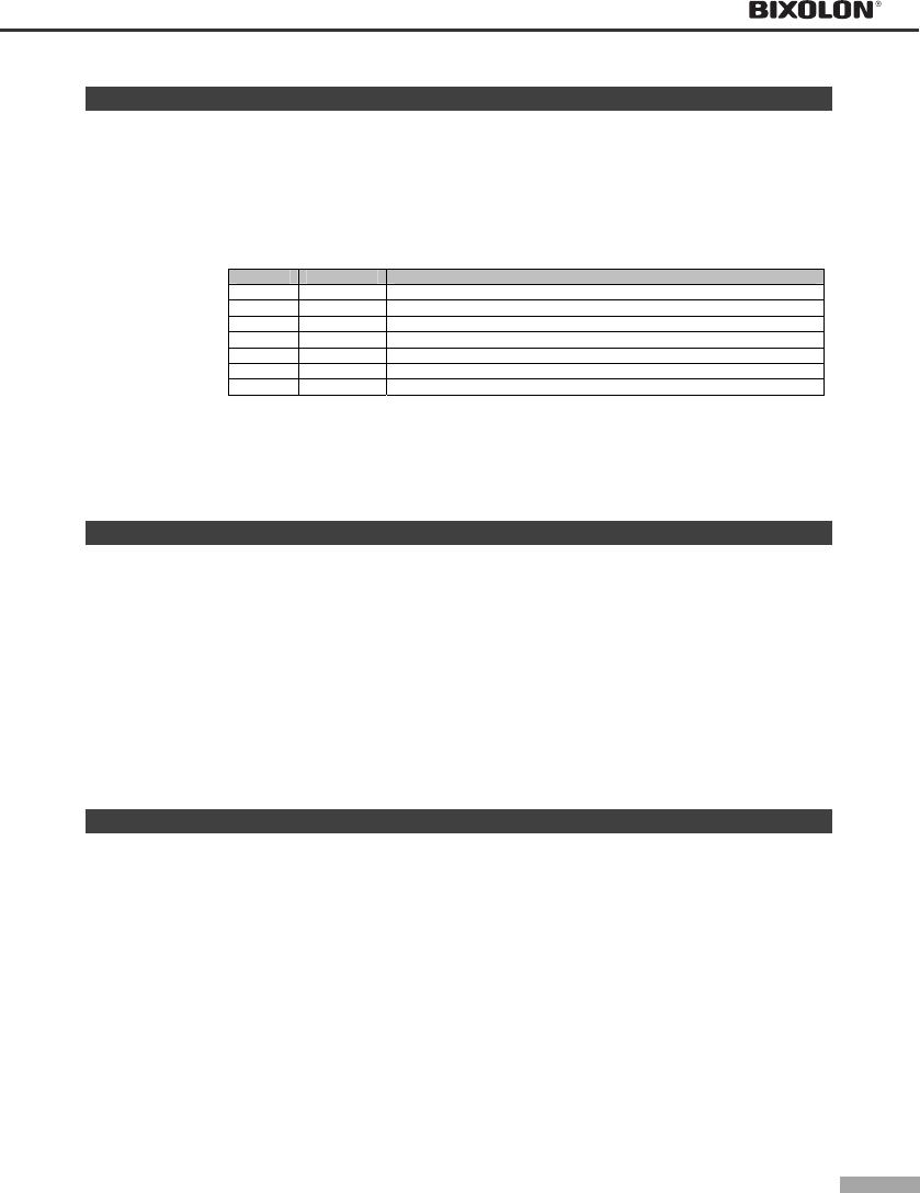
4-18
GS ( C
[Name] Edit NV user memory
[Format] ASCII GS ( C pL pH m fn b [c1, c2] [d1...dk]
Hex 1D 28 43 pL pH m fn b [c1, c2] [d1...dk]
Decimal 29 40 67 pL pH m fn b [c1, c2] [d1...dk]
[Description] Deletes, stores, and transmits data in the NV user memory area based on the functions defined in
the table below. Also sends status information for the amount of space used in NV RAM and the
amount of space still available.
- The function code (fn) specifies the function.
fn Function Description
0, 48 Function 0 Deletes specified record
1, 49 Function 1 Stores data in specified record
2, 50 Function 2 Sends data stored in specified record
3, 51 Function 3 Sends capacity currently being used
4, 52 Function 4 Sends available capacity
5, 53 Function 5 Transmits the key code of the record stored in the NV user memory
6, 54 Function 6 Cancels all records stored in the NV user memory
- pL and pH specify the bytes following parameter pH (m and [a1 b1] ... [ak bk]) as (pL + (pH
x 256)).
- The other parameters are explained under each of the functions.
GS ( C pL pH m fn b c1 c2 <Function 0>
[Format] ASCII GS ( C pL pH m fn b c1 c2
Hex 1D 28 43 05 00 00 fn 00 c1 c2
Decimal 29 40 67 5 0 0 fn 0 c1 c2
[Range] (pL + pH x 256) = 5 (pL = 5, pH = 0)
m = 0
fn = 0, 48
b = 0
32 ≤ c1 ≤ 126
32 ≤ c2 ≤ 126
[Description] Deletes the specified record stored in the NV user memory. The deleted area becomes an “unused”
area available for storage.
GS ( C pL pH m fn b c1 c2 d1...dk <Function 1>
[Format] ASCII GS ( C pL pH m
fn b c1
c2 d1...dk
Hex 1D 28 43 pL pH 00 fn 00 c1 c2 d1...dk
Decimal 29
40 67 pL pH 0 fn 0 c1
c2 d1...dk
[Range] 6 ≤(pL + pH x 256) ≤65535 (0≤ pL ≤255, 0≤ pH ≤255)
m = 0
fn = 1, 49
b = 0
32 ≤ c1 ≤ 126
32 ≤ c2 ≤ 126
32 ≤ d ≤ 254
k = (pL + pH x 256) -5
[Description] Stores data (d1... dk) in the record specified by parameters c1 and c2 (the key code ID numbers).
- When the specified record already exists, the data is overwritten.
- A terminator is automatically assigned.

CHAPTER 4
Control commands list
4-19
GS ( C pL pH m fn b c1 c2 <Function 2>
[Format] ASCII GS ( C pL pH m
fn b
c1 c2
Hex 1D 28 43 05 00 00 fn 00 c1 c2
Decimal 29 40 67 5 0 0 fn 0
c1 c2
[Range] (pL + pH x 256) = 5 (pL = 5, pH = 0)
m = 0
fn = 2, 50
b = 0
32 ≤ c1 ≤ 126
32 ≤ c2 ≤ 126
[Description] Transmits the data for the record with the ID code specified by parameters c1, c2 in the NV user
memory.
- ESC/POS Handshaking Protocol is required for this function.
GS ( C pL pH m fn b <Function 3>
[Format] ASCII GS ( C pL pH m fn b
Hex 1D 28 43 03 00 00
fn 00
Decimal 29 40 67 3
0 0
fn 0
[Range] (pL + pH x 256) = 3 (pL = 3, pH = 0)
m = 0
fn = 3, 51
b = 0
[Description] The printer sends the host the number of data bytes currently used in the NV memory area.
- ESC/POS Handshaking Protocol is not required for this function.
GS ( C pL pH m fn b <Function 4>
[Format] ASCII GS ( C pL pH m fn b
Hex 1D 28 43 03 00 00 fn 00
Decimal 29 40 67 3 0 0
fn 0
[Range] (pL + pH x 256) = 3 (pL = 3, pH = 0)
m = 0
fn = 4, 52
b = 0
[Description] The printer sends the available NV user memory.
- ESC/POS Handshaking Protocol is not required for this function.
GS ( C pL pH m fn b <Function 5>
[Format] ASCII GS ( C pL pH m fn b
Hex 1D 28 43 03 00 00 fn 00
Decimal 29 40 67 3
0 0 fn 0
[Range] (pL + pH x 256) = 3 (pL = 3, pH = 0)
m = 0
fn = 5, 53
b = 0
[Description] Transmits the key code ID for the record stored in the NV user memory.
- ESC/POS Handshaking Protocol is required for this function.
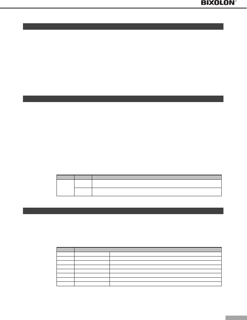
4-20
GS ( C pL pH m fn b d1 d2 d3 <Function 6>
[Format] ASCII GS ( C pL pH m
fn
b d1 d2 d3
Hex 1D 28 43 06 00 00 fn 00 43 4C 52
Decimal 29
40 67 6 0 0 fn 0 67 76 82
[Range] (pL + pH x 256) = 6 (pL = 6, pH = 0)
m = 0
fn = 6, 54
b = 0
d1 = 67
d2 = 76
d3 = 82
[Description] The printer deletes all records stored in the NV user memory.
- All area is changed to unused area.
GS ( D
[Name] Enable/disable real-time command
[Format] ASCII GS ( D pL pH m [a1 b1]...[ak bk]
Hex 1D 28 44 pL pH 14 [a1 b1]...[ak bk]
Decimal 29 40 68 pL pH 20 [a1 b1]...[ak bk]
[Range] (pL + pH x 256) = 3, 5 (pL = 3, 5, pH = 0)
m = 20
a = 1
b = 0, 1, 48, 49
[Default] a = 1/ b = 1 (DLE DC4 fn m t ( n = 1): enable)
[Description] Specifies enable or disable of a real-time command.
- pL, pH sets the number of parameters after pH (m and [a1 b1]...[ak bk]) to (pL + pH x 256)
bytes.
- a specifies the type of real-time command.
- b specifies enable/disable of real-time command processing.
a b Real-time command type
0, 48 Disable DLE DC4 n m t ( n = 1): output a specified pulse in real-time
(It does not process)
1
1, 49 Enable DLE DC4 n m t ( n = 1): output a specified pulse in real-time
(It does process)
DLE DC4 n m t (n=1): output a specified pulse in real-time.
GS ( E
[Name] User setup commands
[Format] ASCII GS ( E pL pH fn [parameters]
Hex 1D 28 45 pL pH fn [parameters]
Decimal 29 40 69 pL pH fn [parameters]
[Description] Controls the user setting modes. The table below explains the functions available in this command.
- The value of fn specifies the function.
fn Function
1 Function1 Changes into the user setting mode
2 Function2 Ends user setting mode session. (Performs a software reset.)
3 Function3 Changes the Memory Switch
4 Function4 Transmits the host the value for the Memory Switch
5 Function5 Changes the customized setting values
6 Function6 Transmits the customized setting values
11 Function11 Sets communication condition of serial interface
12 Function12 Transmits communication condition of serial interface
- pL and pH specify the number of bytes for the parameters following pH (fn and [a1 b1] ...
[ak bk]) as(pL + pH x 256).
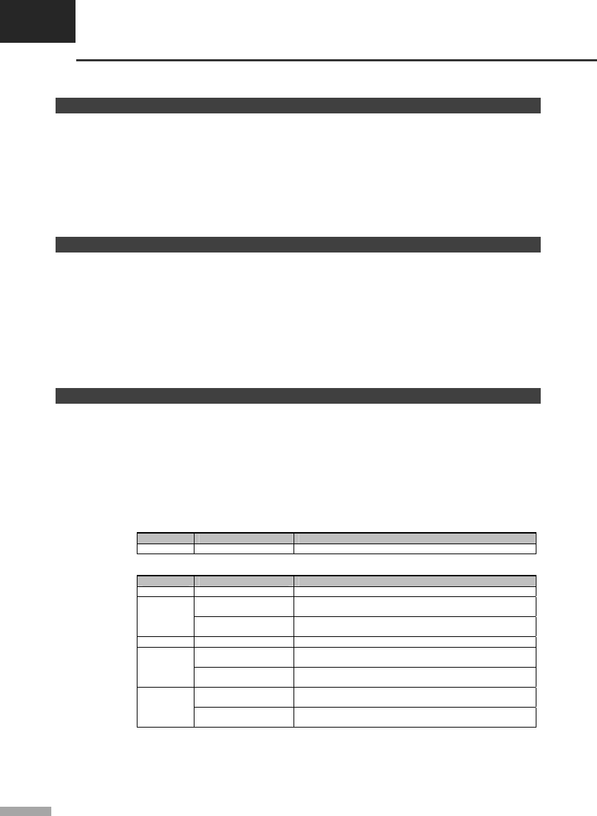
CHAPTER 4
Control commands list
4-21
GS ( E pL pH fn d1 d2 <Function 1>
[Format] ASCII GS ( E pL pH fn
d1 d2
Hex 1D 28 45 03 00 01 49 4E
Decimal 29 40 69 3 0 1 73 78
[Range] (pL + pH x 256) = 3 (pL = 3, pH = 0)
fn = 1
d1 = 73
d2 = 78
[Description] This command changes the printer into the user setting mode.
GS ( E pL pH fn d1 d2 d3 <Function 2>
[Format] ASCII GS ( E pL pH fn d1 d2 d3
Hex 1D 28 45 04 00 02 4F 55 54
Decimal 29 40 69 4 0 2 79 85 84
[Range] (pL + pH x 256) = 4 (pL = 4, pH = 0)
fn = 2
d1 = 79
d2 = 85
d3 = 84
[Description] Ends the user setting mode, and the printer performs a software reset.
GS ( E pL pH fn [a1 b18...b11]...[ak nk8 nk1] <Function 3>
[Format] ASCII GS ( E pL pH fn [a1 b18...b11]...[ak nk8 nk1]
Hex 1D 28 45 pL pH 03 [a1 b18...b11]...[ak nk8 nk1]
Decimal 29 40 69 pL pH 3 [a1 b18...b11]...[ak nk8 nk1]
[Range] a = 2, 8
[Default] All Memory Switches are OFF (b = 48).
[Description] Changes the Memory Switch specified by a to the value specified by b.
- When b = 48, the Memory Switch is set to OFF.
- When b = 49, the Memory Switch is set to ON.
- When b = 50, does not change the Memory Switch.
• When a = 2, Memory Switch 2 is set as follows:
MSW Setting value ( b) Function
2-1 to 2-8 48 Reserved
• When a = 8, Memory Switch 8 is set as follows:
MSW Setting value ( b) Function
8-1 to 8-4 48 Reserved
48 The printer status is sent back as “the paper end” when
the rear cover is opened.
8-5
49 The printer status is sent back “the rear cover open”
when the rear cover is opened.
8-6 48 Reserved: Fixed to OFF (Don’t change the setting)
48 Printer BUSY is released when the remaining capacity of
the receive buffer goes to 640 bytes.
8-7
49 Printer BUSY is released when the remaining capacity of
the receive buffer goes to 522 bytes.
48 Printer rear cover open during operation: Error that
automatically recovers.
8-8
49 Printer rear cover open during operation: Error that can
possibly recover.
- Setting of MSW 8-5 affects the statuses as follows:
• Basic ASB status (See “GS a” command)
• Real-time status (See “DLE EOT” command)
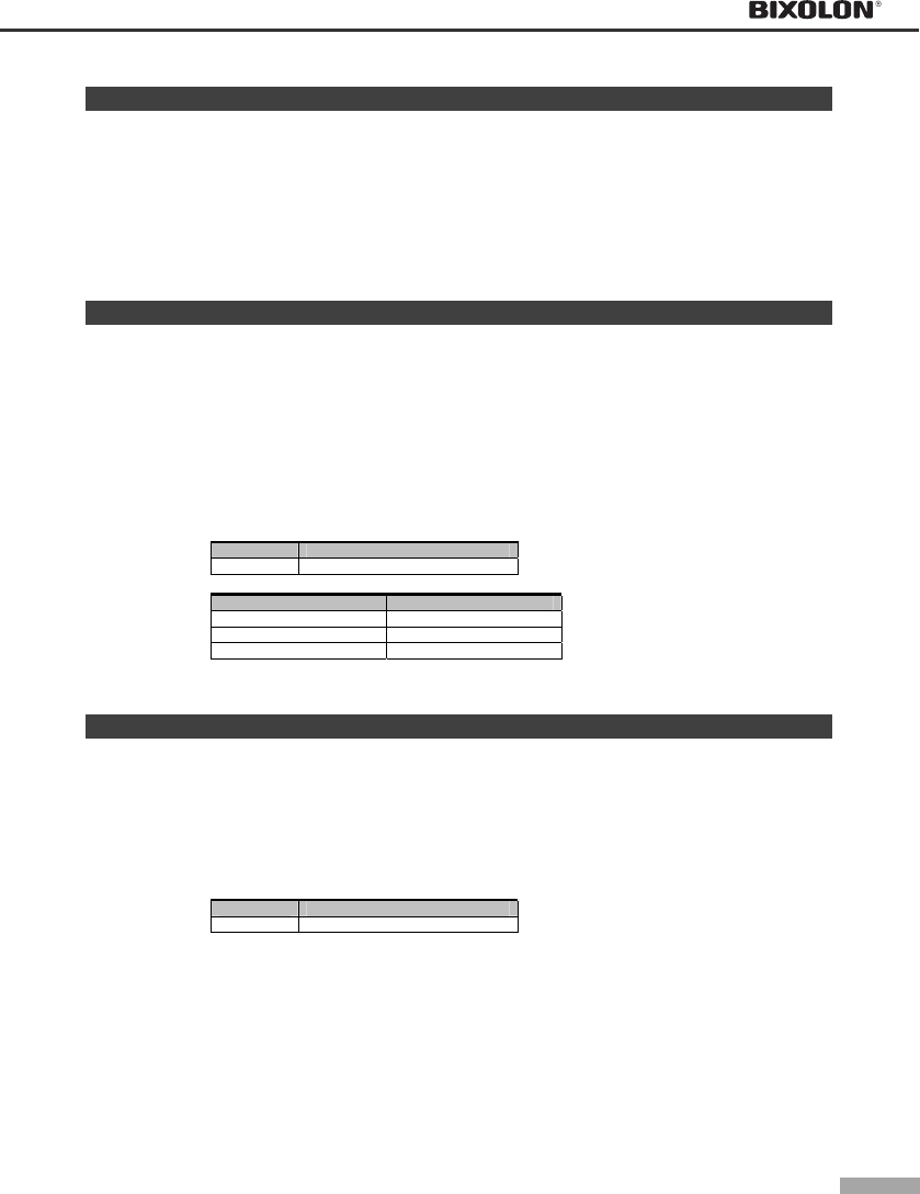
4-22
GS ( E pL pH fn a <Function 4>
[Format] ASCII GS ( E pL pH fn a
Hex 1D 28 45 02 00 04 a
Decimal 29 40 69 2 0 4 a
[Range] (pL + pH x 256) = 2 (pL = 2, pH = 0)
fn = 4
a = 2, 8
[Description] The printer transmits the host the value for the Memory Switch specified by parameter a.
GS ( E pL pH fn [a1 n1L n1H]...[ak nkL nkH] <Function 5>
[Format] ASCII GS ( E pL pH
fn [a1 n1L n1H] ... [ak nkL nkH]
Hex 1D 28 45 pL pH 05 [a1 n1L n1H] ... [ak nkL nkH]
Decimal 29 40 69 pL pH 5 [a1 n1L n1H] ... [ak nkL nkH]
[Range] 4 ≤ (pL + pH x 256) ≤ 65533
(0 ≤ pL ≤ 255, 0 ≤ pH ≤ 255: (pL + pH x 256) = 3 x k + 1)
fn = 5
1 ≤ k ≤ 21844
a = 3
nL + nH x 256 = 2, 4, 5 (nL = 2, 4, 5, nH = 0)
[Default] (nL + nH x 256) = 5 (nL = 5, nH = 0) [default value when a = 3]
[Description] Changes the customized value specified by parameter a to (nL + nH x 256).
a Type of customized value
3 Paper width
[Notes] • Paper width settings (a = 3)
(nL + nH x 256) Paper width
2 57.5mm (2.26 inch)
4 69.5 mm (2.74 inch)
5 76 mm (3.00 inch)
GS ( E pL pH fn a <Function 6>
[Format] ASCII GS ( E pL pH fn
a
Hex 1D 28 45 02 00 06 a
Decimal 29 40 69 2 0 6 a
[Range] (pL + pH x 256) = 2 (pL = 2, pH = 0)
fn = 6
a = 3
[Description] The printer transmits to the host the customized value for the NV memory area specified by
parameter a.
a Type of customized value
3 Paper width
CHAPTER 4
Control commands list
4-23
GS ( E pL pH fn a d1...dk <Function 11>
[Format] ASCII GS ( E pL pH
fn
a d1...dk
Hex 1D 28 45 pL pH 0B a d1...dk
Decimal 29 40 69 pL pH 11 a d1...dk
[Range] 3 ≤ (pL + pH x 256) ≤ 8 (3 ≤ pL ≤ 8, 0 ≤ pH ≤ 255)
fn = 11
1 ≤ a ≤ 4
48 ≤ d ≤ 57 [a = 1]
48 ≤ d ≤ 50 [a = 2]
d = 48, 49 [a = 3]
d = 55, 56 [a = 4]
1 ≤ k ≤ 6
[Default] d1...dk = "9600" [a = 1]
d = 48 [a = 2]
d = 48 [a = 3]
d = 56 [a = 4]
[Description] Changes the condition of the serial interface defined by a.
a Item
1 Baud rate
2 Parity
3 Flow control
4 Bit length
- Baud rate (a = 1) is specified by number.
Example: When defining 19200 bps: 5 bytes as “19200” (Hexadecimal = 31H, 39H, 32H, 30H,
30H / Decimal= 49, 57, 50, 48, 48)
- Parity (a = 2) is specified by d as follows:
d Function
48 Select no parity
49 Select odd parity
50 Select even parity
- Flow control (a = 3) is specified by d as follows:
d Function
48 Select Flow control of DTR/DSR
49 Select Flow control of XON/XOFF
- Bit length (a = 4) is specified by d as follows:
d Function
55 Select 7 bits length
56 Select 8 bits length
GS ( E pL pH fn a <Function 12>
[Format] ASCII GS ( E pL pH
fn
a
Hex 1D 28 45 pL pH 0B a
Decimal 29 40 69 pL pH 11 a
[Range] (pL + pH x 256) = 2 (pL = 2, pH = 0)
fn = 12
1 ≤ a ≤ 4
[Description] Transmits the setting value of the serial interface communication condition specified by a.
[Notes] • This function works in user setting mode and during normal operation.
• This function transmits “Header to NUL” as follows:
a Communication condition
1 Baud rate
2 Parity
3 Flow control
4 Bit length
4-24
GS I
[Name] Transmit printer ID
[Format] ASCII GS I n
Hex 1D 49 n
Decimal 29 73 n
[Range] 1 ≤ n ≤ 3, 49 ≤ n ≤ 51, 65 ≤ n ≤ 68, n = 33
[Default] None
[Description] Transmits 1 byte of printer ID which is specified by n as follows:
n Printer ID Specification
1, 49 Printer model ID Printer model
2, 50 Type ID Printer type
3, 51 Version ID Firmware version
Transmits printer information A (common information), using n as follows:
n Printer ID Specification
33 Type information Supported functions
Transmits printer information B (common information), using n as follows:
n Printer ID Specification
65 Firmware version Firmware version
66 Maker name BIXOLON
67 Printer model Printer model
68 Serial No Serial No of the printer
GS V
[Name] Select cut mode and cut paper
[Format] Function A ASCII GS V m
Hex 1D 56 m
Decimal 29 86 m
Function B ASCII GS V m n
Hex 1D 56 m n
Decimal 29 86 m n
[Range] Function A m = 0, 1, 48, 49
Function B m = 65, 66; 0 ≤ n ≤ 255
[Default] None
[Description] Select a paper cutting mode using m and then cut the paper, as follows:
m Function
0,48 Executes a full cut (cuts the paper completely).
<A> 1,49 Executes a partial cut (one point left uncut).
65 Feeds paper to (cutting position + n × vertical motion unit) and executes
a partial cut(one point left uncut).
<B>
66 Feeds paper to (cutting position + n × vertical motion unit) and executes
a partial cut(one point left uncut).
[Note for <A>] • If an auto cutter is not provided, this command is ignored.
[Notes for <B>] • When n = 0, the printer feeds the paper to the cutting position and cuts it.
• If an auto cutter is not provided, the printer only feeds the paper for specified amount.
• Vertical motion unit is used for calculating a paper feed amount.
CHAPTER 4
Control commands list
4-25
GS a
[Name] Enable/disable Automatic Status Back (ASB)
[Format] ASCII GS a n
Hex 1D 61 n
Decimal 29 97 n
[Range] 0 ≤ n ≤ 255
[Default] When DIP Switch or Memory Switch (BUSY condition) is Off: n = 0
When DIP Switch or Memory Switch (BUSY condition) is On: n = 2
[Description] Enables or disables basic ASB (Automatic Status Back) and specifies the status items to include,
using n as follows:
Bit On/Off Hex Decimal Status for ASB
Off 00 0 Drawer kick-out connector pin 3 status disabled.
0 On 01 1 Drawer kick-out connector pin 3 status enabled.
Off 00 0 On-line/off-line disabled.
1 On 02 2 On-line/off-line enabled
Off 00 0 Error status disabled.
2 On 04 4 Error status enabled.
Off 00 0 Paper sensor status disabled.
3 On 08 8 Paper sensor status enabled.
4 - - - Undefined.
5 - - - Undefined.
6 - - - Undefined.
7 - - - Undefined.
4-26
[Notes] • Basic ASB status is 4-byte configuration [first byte - fourth byte].
• The status to be transmitted are as follows:
• First byte (printer information)
Bit On/Off Hex Decimal Function
0 Off 00 0 Not used. Fixed to Off.
1 Off 00 0 Not used. Fixed to Off.
Off 00 0 Drawer kick-out connector pin 3 is LOW.
2 On 04 4 Drawer kick-out connector pin 3 is HIGH.
Off 00 0 On-line.
3 On 08 8 Off-line.
4 On 10 16 Not used. Fixed to On.
Off 00 0 Rear cover is close
5 On 20 32 Rear cover is open
Off 00 0 Paper is not being fed by the paper feed button.
6 On 40 64 Paper is being fed by the paper feed button.
7 Off 00 0 Not used. Fixed to Off.
• Second byte (printer information)
Bit On/Off Hex Decimal Function
0 Off 00 0 Not used. Fixed to Off.
1 Off 00 0 Not used. Fixed to Off.
Off 00 0 No mechanical error.
2 On 04 4 Mechanical error.
Off 00 0 No auto cutter error.
3 On 08 8 Auto cutter error occurred.
4 Off 00 0 Not used. Fixed to Off.
Off 00 0 No unrecoverable error.
5 On 20 32 Unrecoverable error.
Off 00 0 No automatically recoverable error.
6 On 40 64 Automatically recoverable error occurred.
7 Off 00 0 Not used. Fixed to Off.
• Third byte (paper sensor information)
Bit On/Off Hex Decimal Function
Off 00 0 Paper near end sensor: paper adequate.
0,1 On 03 3 Paper near end sensor: paper near end.
Off 00 0 Paper end sensor: paper present.
2,3 On 0C 12 Paper end sensor: no paper present.
4 Off 00 0 Not used. Fixed to Off.
5 Off 00 0 Not used. Fixed to Off.
6 Off 00 0 Not used. Fixed to Off.
7 Off 00 0 Not used. Fixed to Off.
• Forth byte
Bit On/Off Hex Decimal Function
0 On 01 1 Not used. Fixed to On.
1 On 02 2 Not used. Fixed to On.
2 On 04 4 Not used. Fixed to On.
3 On 08 8 Not used. Fixed to On.
4 Off 00 0 Not used. Fixed to Off.
5 Off 00 0 Not used. Fixed to Off.
6 Off 00 0 Not used. Fixed to Off.
7 Off 00 0 Not used. Fixed to Off.
CHAPTER 4
Control commands list
4-27
GS r
[Name] Transmit status
[Format] ASCII GS r n
Hex 1D 72 n
Decimal 29 114 n
[Range] n = 1, 2, 49, 50
[Description] Transmits 1 byte of status data using n as follows:
n Function
1, 49 Transmits paper sensor status
2, 50 Transmits drawer kick-out connector status
[Notes] • Each status is 1 byte.
• The status to be transmitted is as follows:
- Paper sensor status (n = 1, 49)
Bit Binary Hex Decimal Status
00 00 0 Paper near end sensor: paper adequate.
0, 1 11 03 3 Paper near end sensor: paper not present.
00 00 0 Paper end sensor: paper present.
2, 3 11 0C 12 Paper end sensor: paper not present.
4 0 00 0 Not used. Fixed to Off.
5,6 - - - Undefined.
7 0 00 0 Not used. Fixed to Off.
• The status to be transmitted is as follows:
- Drawer kick-out connector status (n = 2, 50)
Bit Binary Hex Decimal Status
0 00 0 Drawer kick-out connector pin 3 is LOW.
0 1 01 1 Drawer kick-out connector pin 3 is HIGH.
1-3 - - - Undefined.
4 0 00 0 Not used. Fixed to Off.
5,6 Undefined
7 0 00 0 Not used. Fixed to Off.
4-28
▌4.4.3 Commands list for STAR mode (SP500)
n Command Description Hex
1 ESC GS t Specify code page 1B 1D 74
2 ESC R Specify international character set 1B 52
3 ESC / Specify/cancel slash zero 1B 2F
4 ESC M Specify 7×9 font (half dots) 1B 4D
5 ESC P Specify 9×9 font 1B 50
6 ESC : Specify 5×9 font (3P-1) 1B 3A
7 ESC SP Specify character space 1B 20
8 SO Specify double-wide expanded characters 0E
9 DC4 Cancel double wide printing 14
10 ESC W Specify/cancel double-wide printing 1B 57
11 ESC h Specify/cancel double-high printing 1B 68
12 ESC E Select emphasized printing 1B 45
13 ESC F Cancel emphasized printing 1B 46
14 ESC - Select/cancels underline mode 1B 2D
15 ESC _ Select/cancels upperline mode 1B 5F
16 ESC 4 Specify white/black inversion and red color printing 1B 34
17 ESC 5 Cancel white/black inversion and specify black color printing 1B 35
18 SI Select upside-down printing 0F
19 DC2 Cancel upside-down printing 12
20 ESC RS i Specify/cancel rotating print mode 1B 1E 69
21 LF Line feed 0A
22 CR Line feed (according to Memory Switch settings) 0D
23 ESC a Feed paper n lines 1B 61
24 ESC 0 Set line feed to 1/8 inch 1B 30
25 ESC 1 Set line feed to 7/72 inch 1B 31
26 ESC z 0("0") Set line feed to 1/12 inch 1B 7A 00(30)
27 ESC z 1("1") Set line feed to 1/6 inch 1B 7A 01(31)
28 ESC J Execute n/72 inch paper feed one time 1B 4A
29 ESC A Define n/72 inch pitch line feed 1B 41
30 ESC 2 Set ESC A line feed pitch 1B
31 ESC 3 Set line feed to n/216 inch line feed pitch (approximate value) 1B 33
32 ESC y Set line feed to n/144 inch line feed pitch 1B 79
33 ESC I Execute n/144 inch paper feed one time 1B 49
34 FF Form feed 0C
35 ESC C Set page length to n lines 1B 43
36 ESC C 0 Set page length to n inches 1B 43 00
37 VT Feed paper to vertical table position 0B
38 ESC B Set vertical tab position 1B 42
39 ESC N Set bottom margin to n lines 1B 4E
40 ESC O Cancel bottom margin 1B 4F
41 ESC l Set left margin 1B 6C
42 ESC Q Set right margin 1B 51
43 HT Move print position to horizontal tab position 09
44 ESC D Set/cancel horizontal tab position 1B 44
45 ESC GS a Specify position alignment 1B 1D 61
46 ESC GS A Specify absolute position 1B 1D 41
47 ESC GS R Specify relative position 1B 1D 52
48 ESC & Register/delete download characters 1B 26
49 ESC % Set/cancel download characters 1B 25
50 ESC K Standard density bit image 1B 4B
CHAPTER 4
Control commands list
4-29
n Command Description Hex
51 ESC L Double density bit image 1B 4C
52 ESC d Paper cut instruction 1B 64
53 ESC BEL Set pulse width for external device drive 1B 07
54 BEL External device 1 drive instruction 07
55 FS External device 1 drive instruction (real time) 1C
56 SUB External device 2 drive instruction (real time) 1A
57 EM External device 2 drive instruction (real time) 19
58 ENQ Inquire ENQ status 05
59 EOT Inquire EOT status 04
60 ESC ACK SOH Inquire status 1B 06 01
61 ESC RS a Set status transmission conditions 1B 1E 61
62 ETB Update ETB status (check after printing) 17
63 ESC RS E Clear the ETB counter and ETB status 1B 1E 45
64 DC3 Printer deselect 13
65 DC1 Printer select 11
66 ESC @ Command initialization 1B 40
67 ESC U Select printing direction 1B 55
68 ESC GS # Set Memory Switch 1B 1D 23
69 ESC # Set Memory Switch 1B 23
70 ESC ? LF NUL Reset printer and test print 1B 3F 0A 00
4-30
▌4.4.4 Commands list for CITIZEN mode (iDP3550/3551)
n Command Description Hexadecimal
1 FF n n-line paper feed (CBM1 mode) 0C n
2 FF Form feed (CBM2 mode) 0C
3 SO (Note) Specifying the double width character (CBM1 mode) 0E
4 SI (Note) Canceling the double width character 0F
5 LF Print and paper feed 0A
6 CR Printing 0D
7 DC1 (Note) Initializing the printer (CBM1 mode) 11
8 DC2 (Note) Specifying/Canceling the inverted character (CBM1 mode) 12
9 DC3 (Note) Specifying the red print (CBM1 mode) 13
10 CAN Canceling the print data 18
11 ESC * n1 n2 Specifying the bit image mode 1B 2A n1 n2
12 ESC - n Specifying/Canceling the Underline 1B 2D n
13 ESC 1 Specifying 1/9-inch line feed width 1B 31H
14 ESC 2 Specifying 2/9-inch line feed width 1B 32
15 ESC 3 Specifying standard line feed width 1B 33
16 ESC C n Setting the page length 1B 43 n
17 ESC N n Specifying the perforation skip 1B 4E n
18 ESC O Canceling the perforation skip 1B 4F
19 ESC f 1 Form feed (Changing the page) 1B 66 01
20 ESC t n Selecting the character code table 1B 74 n
21 ESC BEL n1 n2 Setting the external device drive pulse width 1B 07 n1 n2
22 BEL Driving command A for Drawer-1 07
23 FS Driving command B for Drawer-1 1C
24 SUB Driving command for Drawer-2 1A
25 RS Buzzer-on 1E
26 ESC P 0 Partial cut 1B 50 00
27 ESC P 1 Partial cut 1B 50 01
28 ESC R n Selecting the international character set 1B 52 n
29 ESC & 0 n1 n2 Defining the download character set 1B 26 00 n1 n2
30 ESC % n Specifying/Canceling the download character 1B 25 n
31 ESC / n Defining the message 1B 2F n
32 ESC DC3 n Printing the message 1B 13 n
33 ESC y n Setting the print lines after paper near end detection 1B 79 n
34 ESC DC2 n1 n2 Deleting the download character, message, bit image 1B 12 n1 n2
35 GS * n1 n2 Defining the download bit image 1D 2A n1 n2
36 GS / m Printing the download bit image 1D 2F m
CHAPTER 5
Reference information
5-1
▌5.1 Printing specification
Item Description Remark
Printing method Serial impact method
Head wire 9 pin serial type
Dot pitch 0.352mm (1/72”)
Dot wire diameter 0.3mm (0.01”)
Printing direction Bidirectional (logic seeking) with friction feed
Characters per line Max. 42 (characters)
Printing speed 5.1 LPS (Line Per Second) at 40 column
Printing width 63.34 mm (2.49”)
Line interval 4.233 mm (1/6”)
Paper feed method Friction feed
Paper feed speed Approximately 158 mm (6.2”)
Character font 7 x 9 / 9 x 9
Character sets
Alphanumeric characters : 95
International characters : 32
Extended graphics : 128 x 25 pages
▌5.2 Paper specifications
Item Description Remark
Paper type Paper roll
Paper roll width 76±0.5 mm, 69.5±0.5 mm, 57.5±0.5mm
Paper roll diameter Max. ø83 mm (3.27")
Normal paper Thickness : 1 sheet 0.07~0.085 mm (0.0028~0.0034")
Weight : 52.3~64g/m2 (0.115~0.1411 lb)
Paper core outside diameter Max. ø19mm (0.75")
▌5.3 Ribbon cassette specification
Item Description Remark
Standard SRP 275 B/R
Color Black & Red
Size 13 mm (W)
Life SRP 275 B/R : 1,500,000 characters (Black)
750,000 characters (Red)
Continuous printing 7x9 font
ASCII
25℃
NOTES
Malfunctions and other problems may arise if other than specified ribbon cassettes are used in the printer.
The Warranty may be void if other than specified ribbon cassettes are used. Contact your dealer or place
of purchase for more information about proper ribbon cassettes.
5-2
▌5.4 Electrical characteristics
Item Description Remark
Supply voltage 24V DC ± 10%
Operating Mean : Approximately 0.5A
Peak : Approximately 1.5A
Current consumption
(at 24V, except for drawer
kick-out driving) Standby Mean: Approximately 0.3A
NOTES
Maximum 1A for drawer kick-out driving.
▌5.5 Reliability
Item Description Remark
Life firing frequency
Mechanism : Approx. 10 million lines
Auto cutter : Approx. 1 million cuts
(End of life is defined as the point at which the printer
reaches the beginning of the Wear out Period.)
Head Approx. 300 million dots/wire
▌5.6 Environment conditions
Item Description Remark
Temperature Operating : 0~50℃ (32~122℉)
Storage : -10~50℃ (14~122℉)
Relative humidity Operating : 10~90% RH (Non-condensing)
Storage : 10~90% RH (Non-condensing)
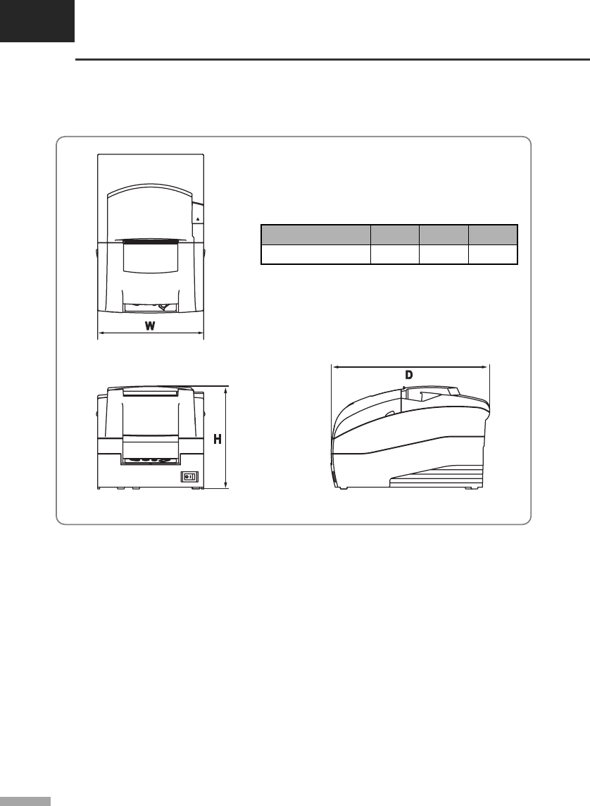
CHAPTER 5
Reference information
5-3
▌5.7 Dimensions & weight
• Dimensions
• Weight
Approx. Wt. : 2.5 kg
Shipping Wt. : 4.0 kg
▌5.8 Optional features
The optional features either replace a standard feature or enhance the operation of the printer.
All optional features are installed at the factory and must be selected when the printer is ordered.
------------------------------------------------------------------------------------------------------------------------------------------------
• Auto cutter (SRP-275A : Exclude auto cutter, SRP-275C : Including auto cutter)
------------------------------------------------------------------------------------------------------------------------------------------------
• Interface (Serial / Parallel / USB / Ethernet)
------------------------------------------------------------------------------------------------------------------------------------------------
• Cabinet color (Ivory / Dark gray)
------------------------------------------------------------------------------------------------------------------------------------------------
157239160Dimension (mm)
HDWItem
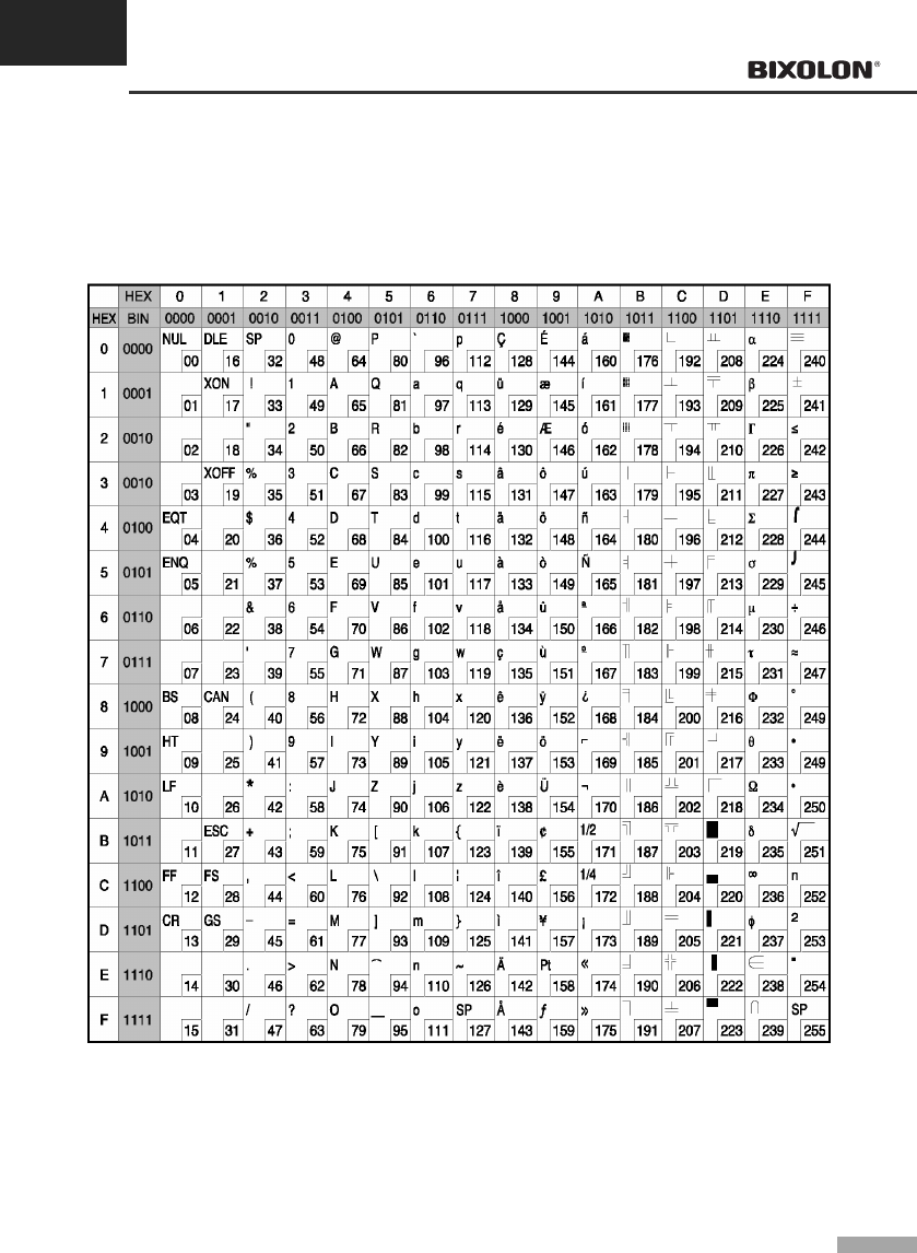
APPENDIX A
Code tables
A-1
The following pages show the character code tables.
To fine the character corresponding to a hexadecimal number, count across the top of the table for the left
digit and count down the left column of the table right digit. For example, 4A=J.
▌A.1 Page 0 (PC 437 : USA, Standard Europe
(International Character Set : USA))
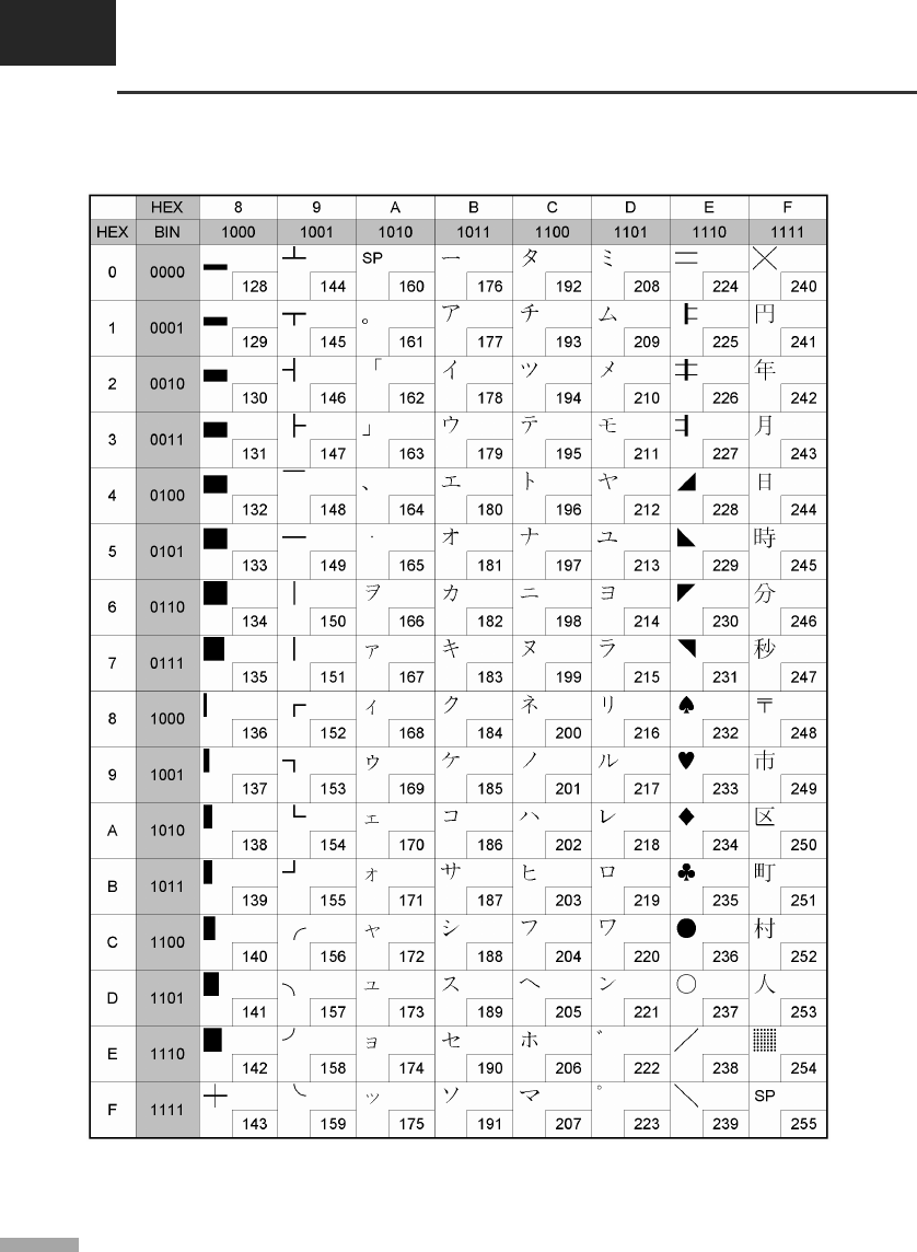
APPENDIX A
Code tables
A-2
▌A.2 Page 1 (Katakana)
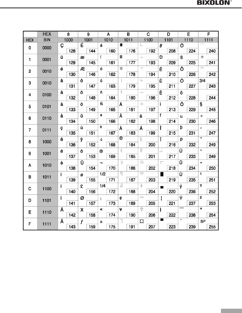
A-3
▌A.3 Page 2 (PC850 : Multilingual)
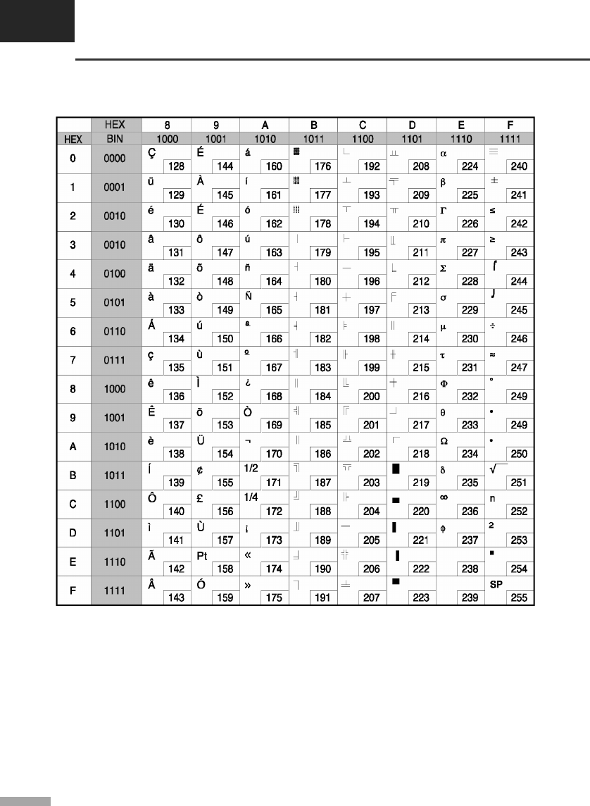
APPENDIX A
Code tables
A-4
▌A.4 Page 3 (PC860 : Portuguese)
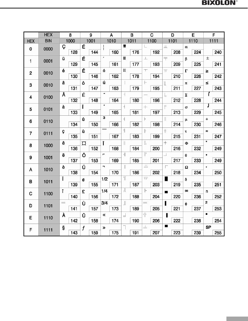
A-5
▌A.5 Page 4 (PC863 : Canadian-French)
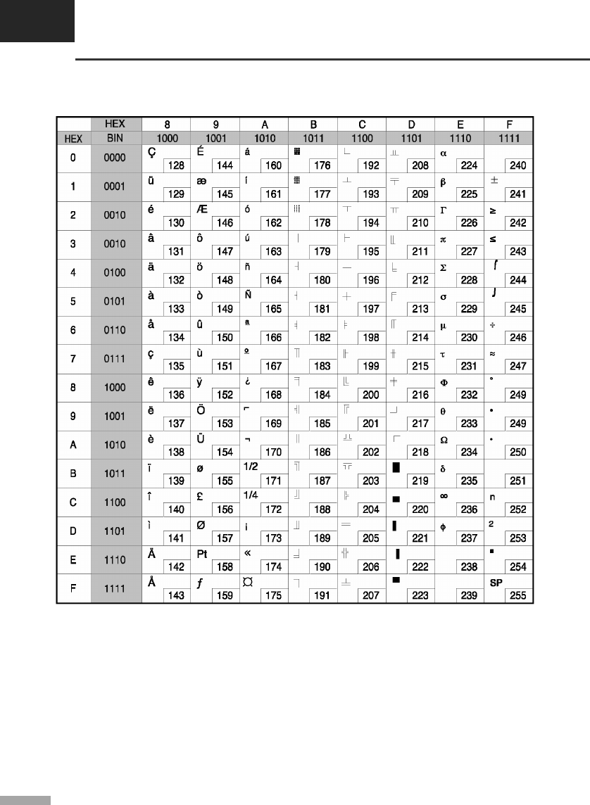
APPENDIX A
Code tables
A-6
▌A.6 Page 5 (PC865 : Nordic)
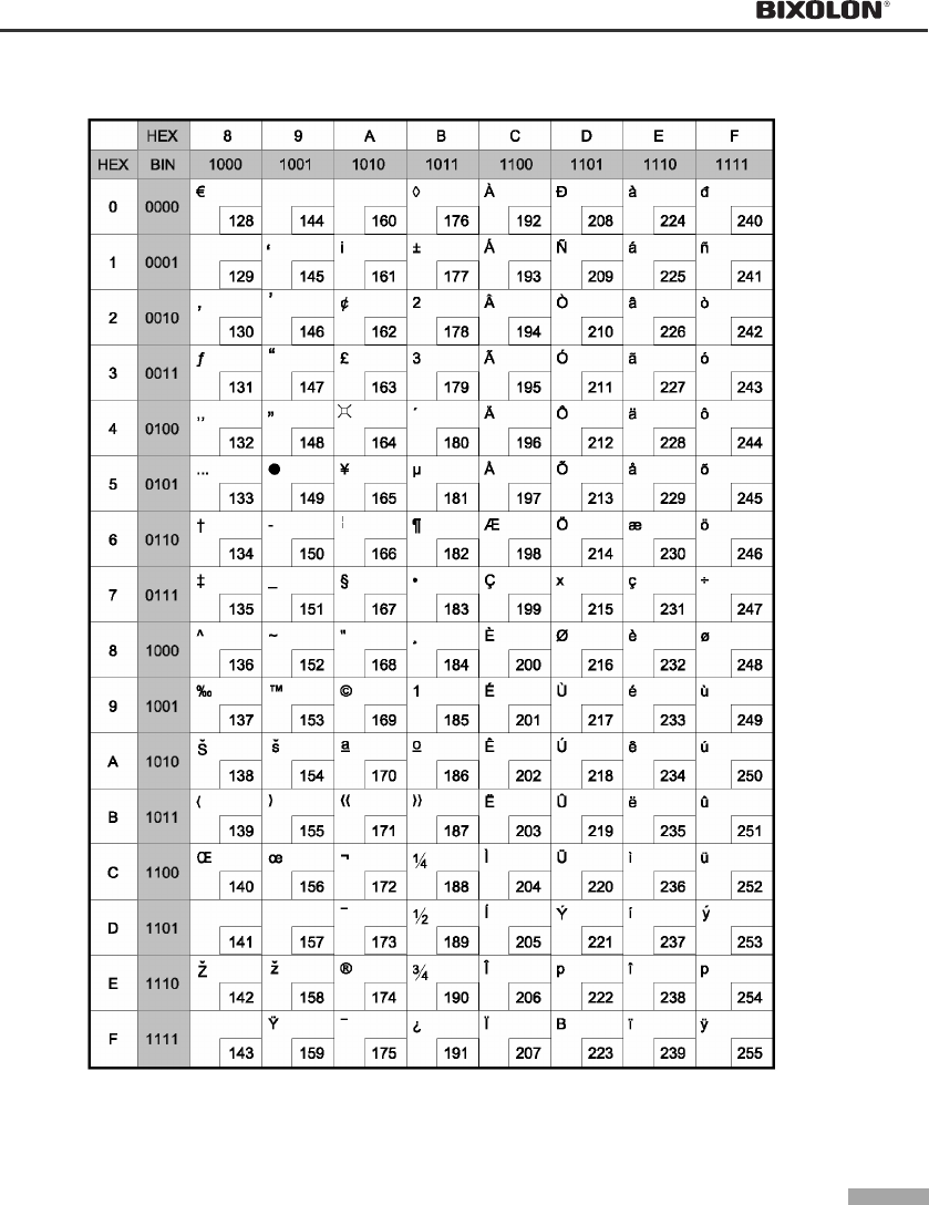
A-7
▌A.7 Page 16 (WPC1252 : Latin1)
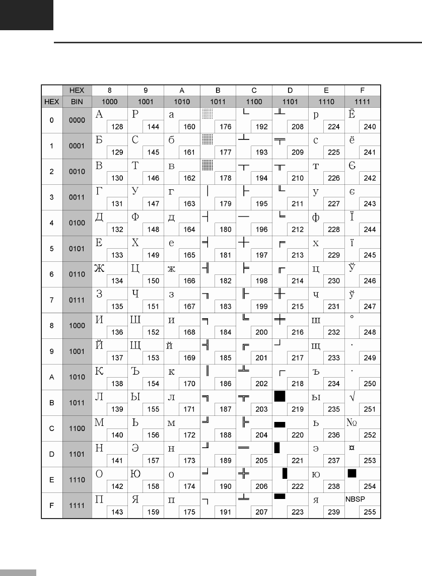
APPENDIX A
Code tables
A-8
▌A.8 Page 17 (PC866 : Russian)
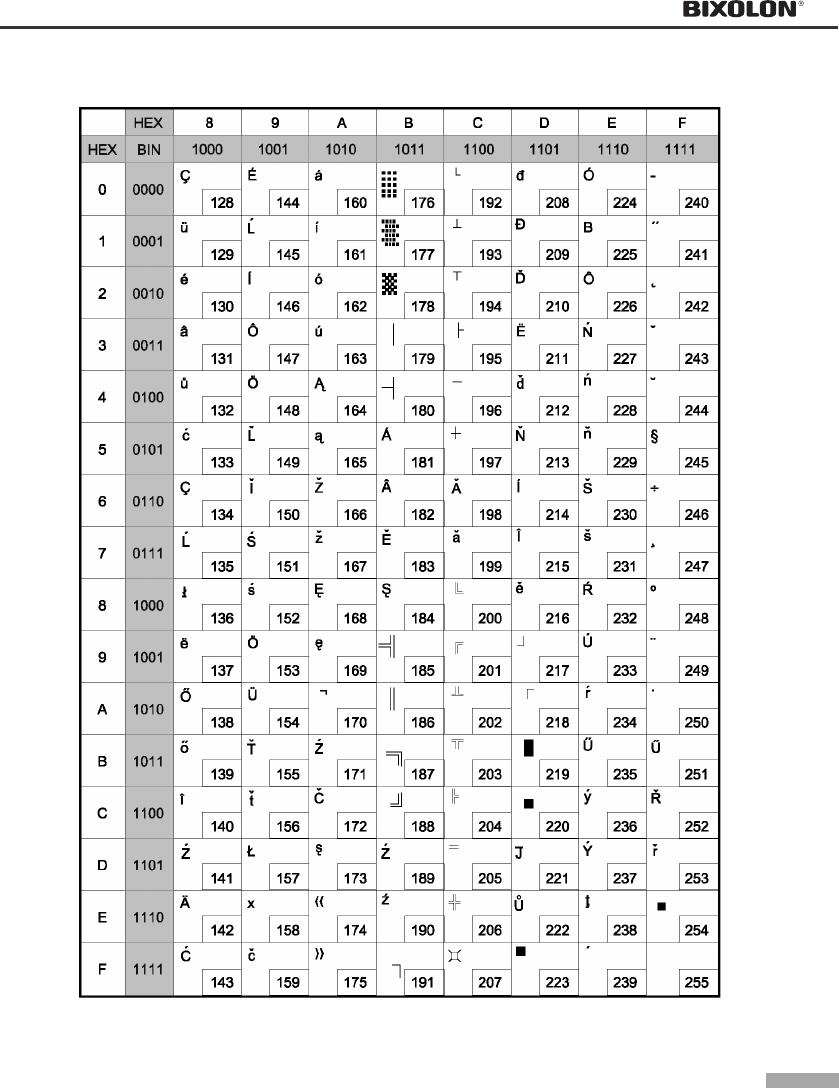
A-9
▌A.9 Page 18 (PC852 : Latin2)
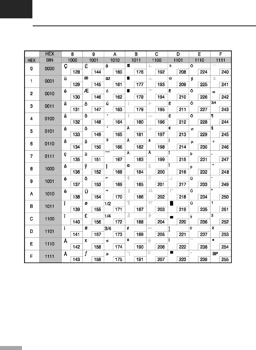
APPENDIX A
Code tables
A-10
▌A.10 Page 19 (PC858 : Euro)

A-11
▌A.11 Page 21 (PC862 : Israel)
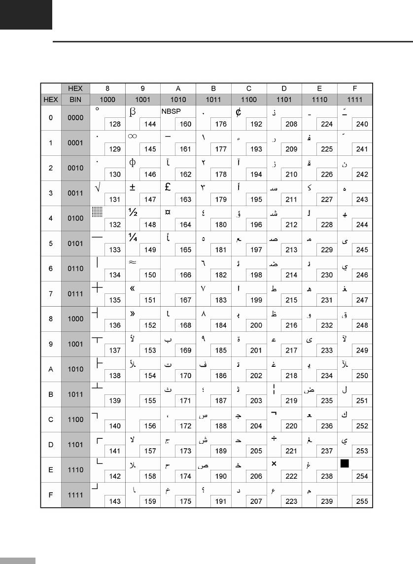
APPENDIX A
Code tables
A-12
▌A.12 Page 22 (PC864 : Arabic)
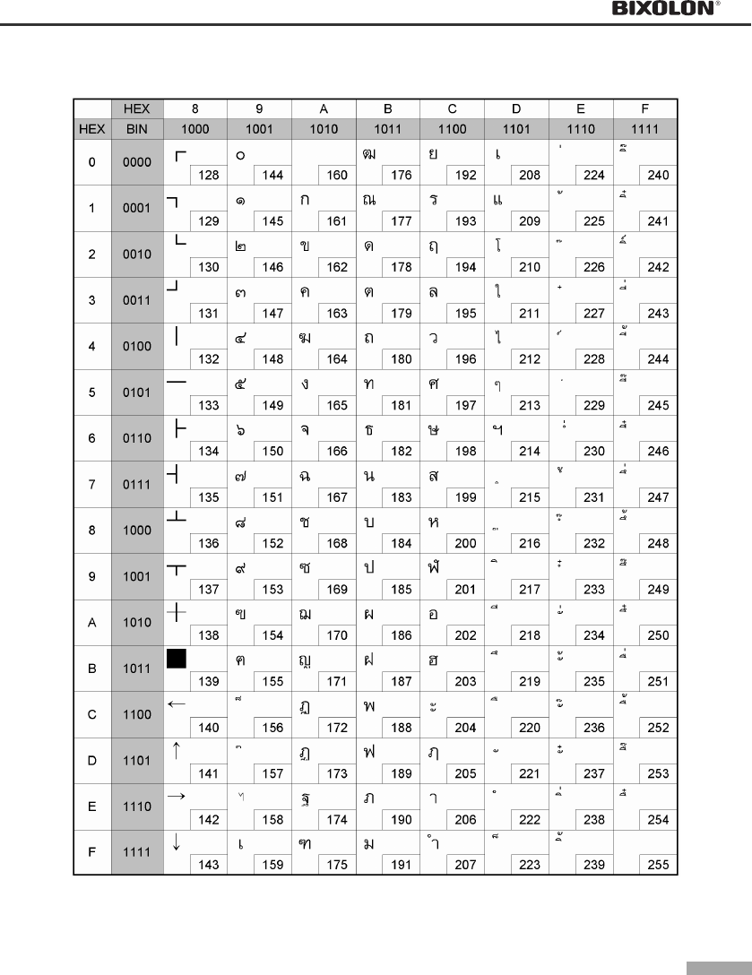
A-13
▌A.13 Page 23 (Thai character code 42)
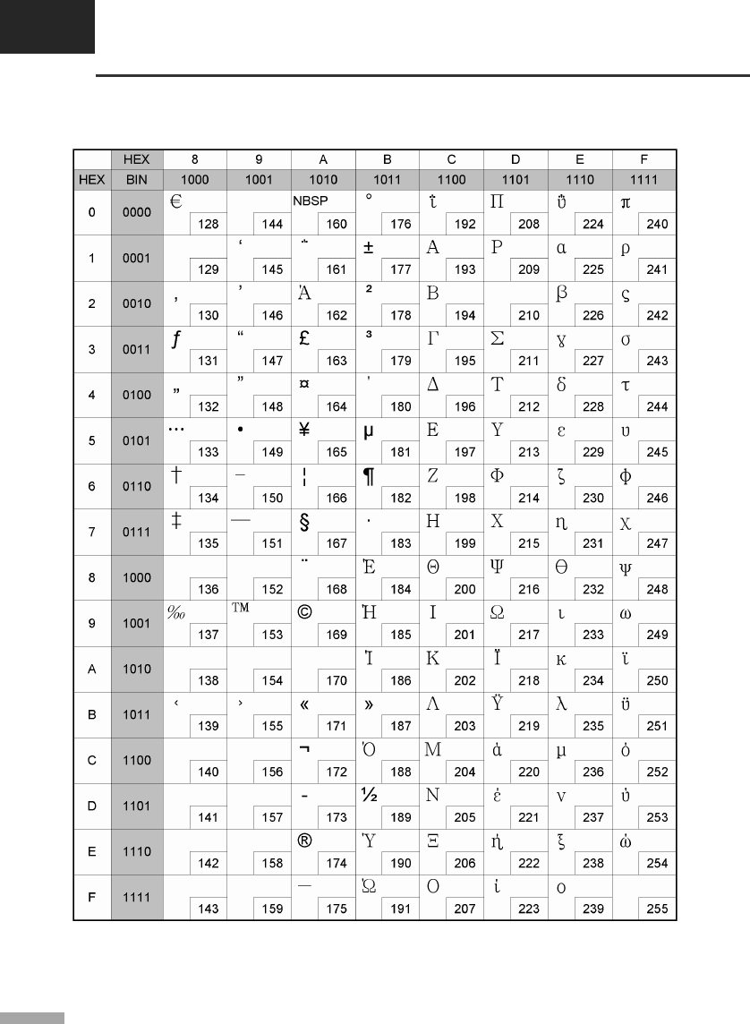
APPENDIX A
Code tables
A-14
▌A.14 Page 24 (WPC1253 : Greek)
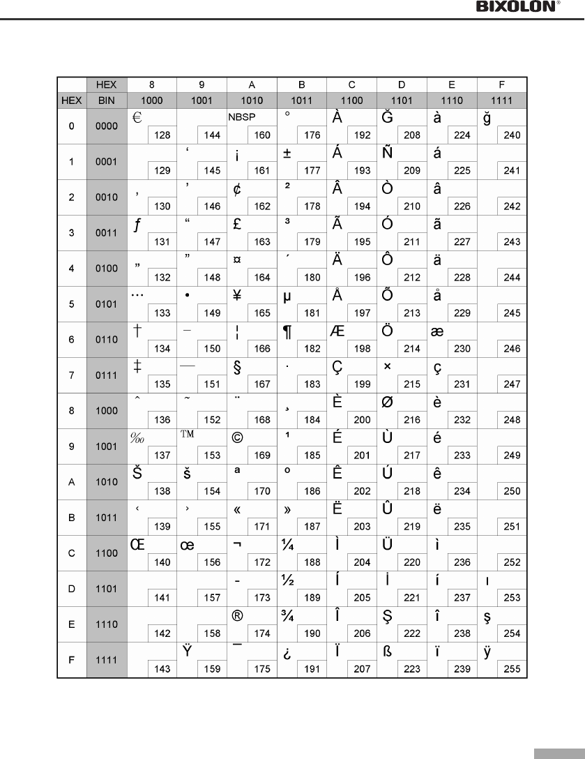
A-15
▌A.15 Page 25 (WPC1254 : Turkish)
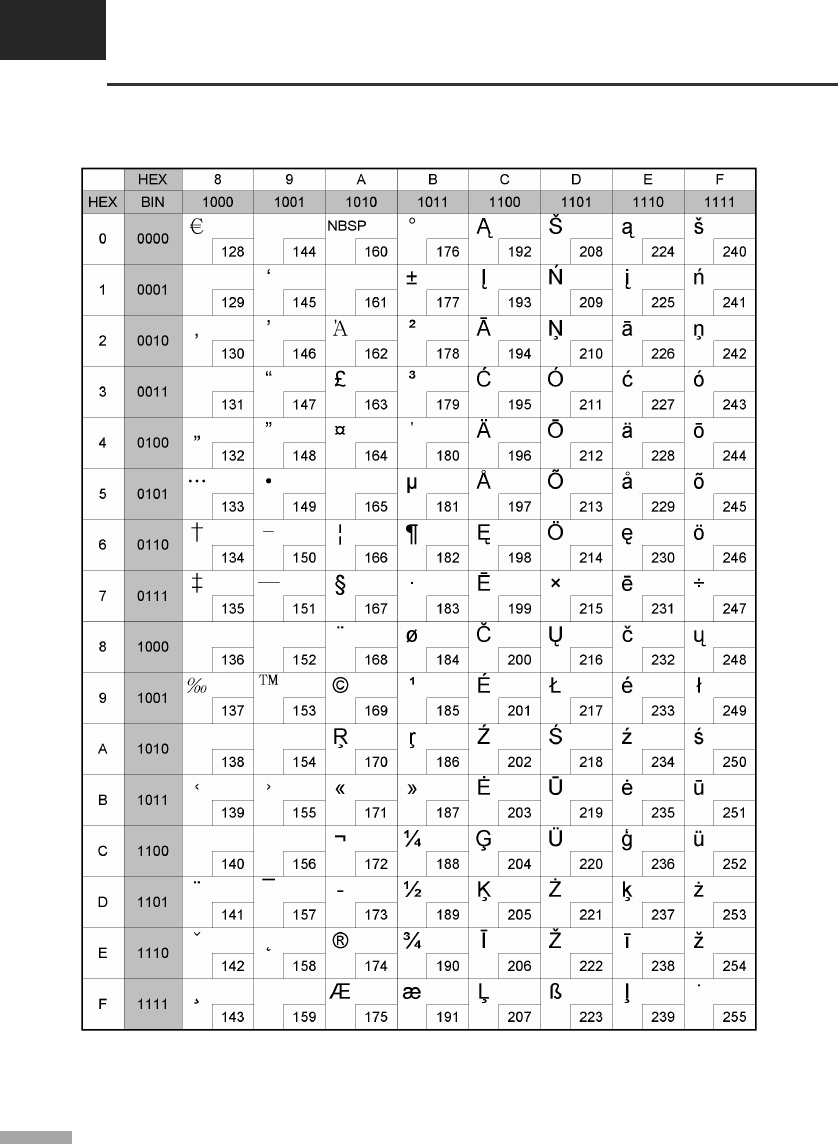
APPENDIX A
Code tables
A-16
▌A.16 Page 26 (WPC1257 : Baltic)
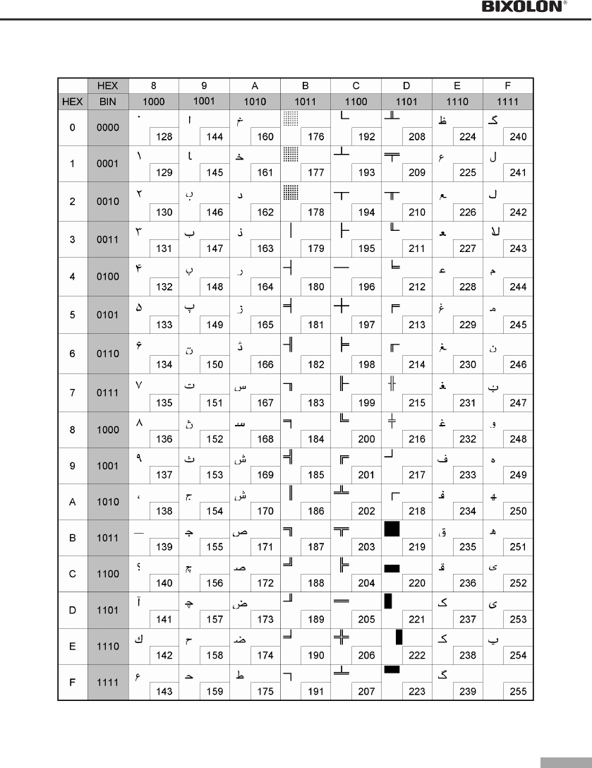
A-17
▌A.17 Page 27 (Farsi)
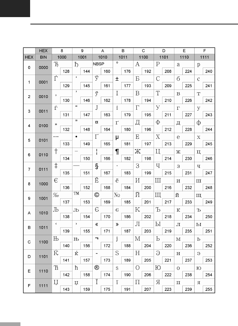
APPENDIX A
Code tables
A-18
▌A.18 Page 28 (WPC1251 : Russian)
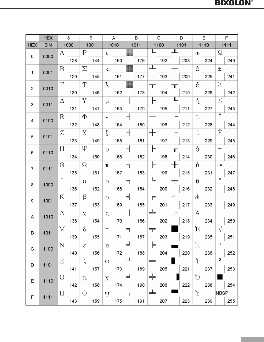
A-19
▌A.19 Page 29 (PC737 : Greek)

APPENDIX A
Code tables
A-20
▌A.20 Page 30 (PC775 : Baltic)
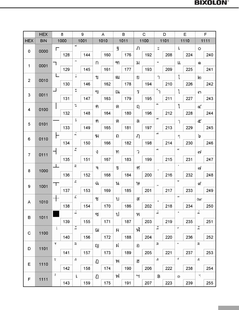
A-21
▌A.21 Page 31 (Thai character code 16)
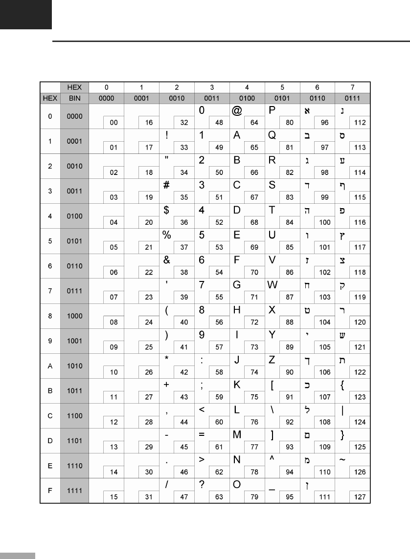
APPENDIX A
Code tables
A-22
▌A.22 Page 32 (OldCode : Israel)
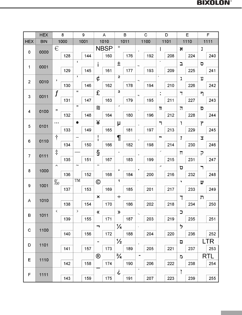
A-23
▌A.23 Page 33 (WPC1255 : Israel)
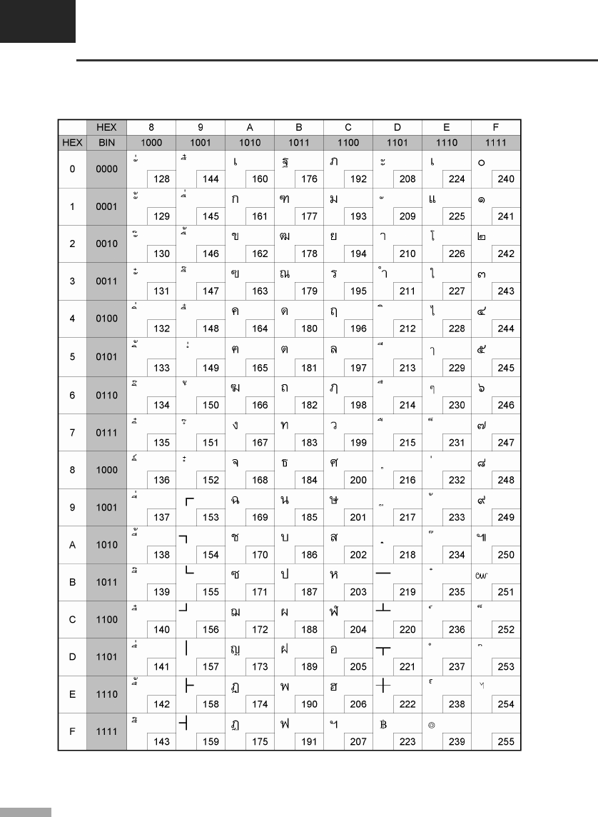
APPENDIX A
Code tables
A-24
▌A.24 Page 34 (Thai character code 11)

A-25
▌A.25 Page 35 (Thai character code 18)
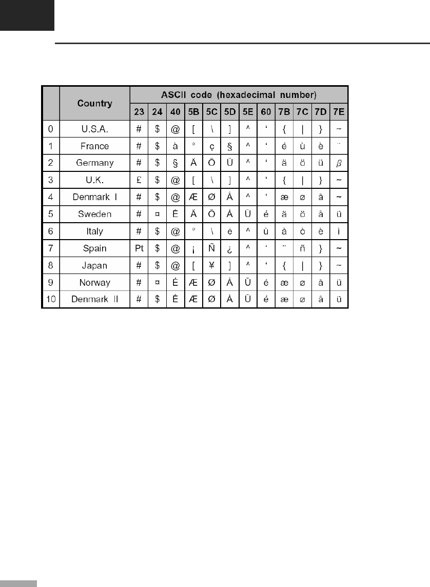
APPENDIX A
Code tables
A-26
▌A.26 International character code table
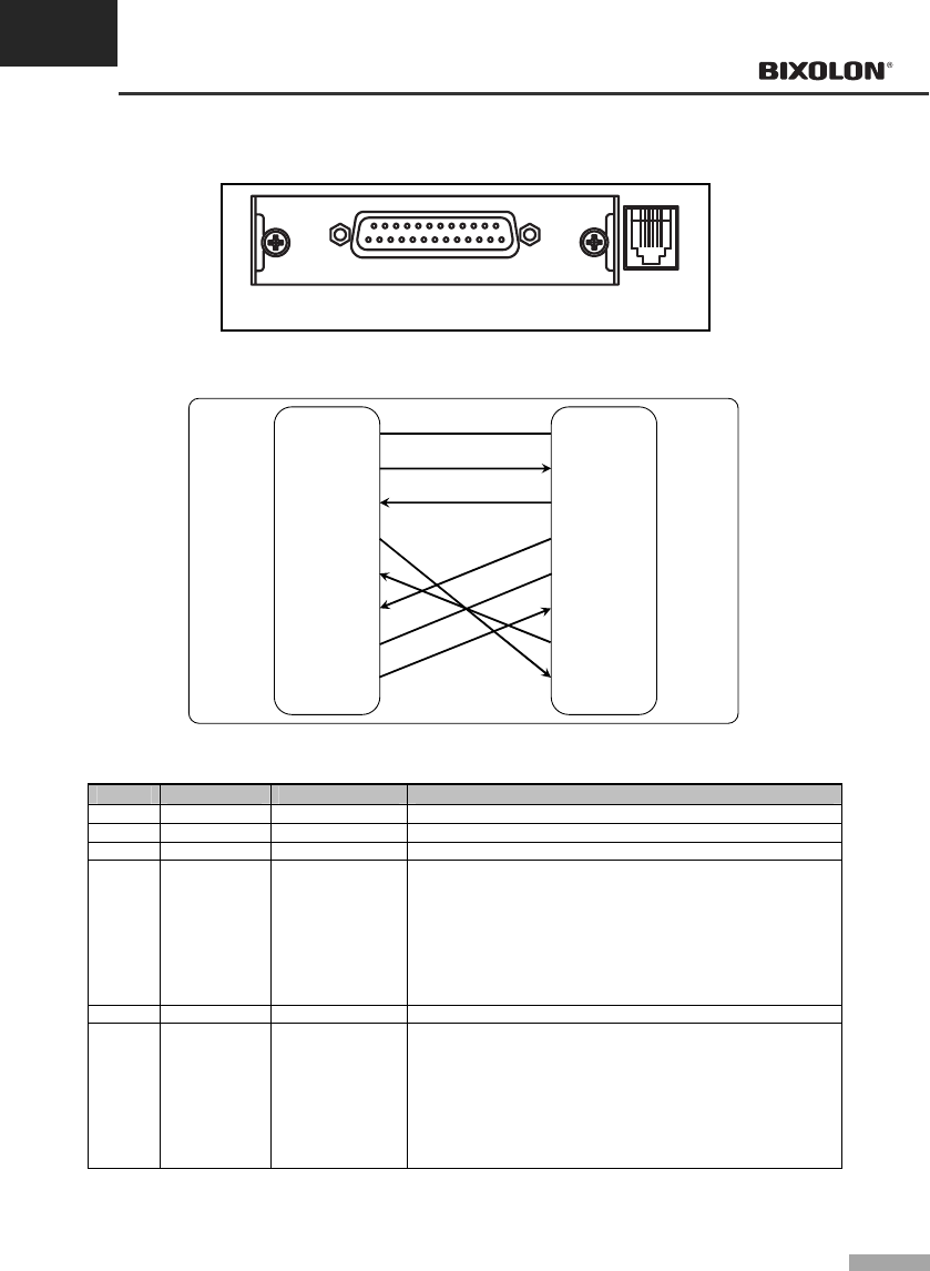
APPENDIX B
Connectors
B-1
▌B.1 RS-232C Serial I/F
RS-232
Interface connector Drawer kick-out
Connector
▌B.1.1 RS-232C Serial I/F cable connection
(F.G) 1
(TXD) 2
(RXD) 3
(RTS) 4
(CTS) 5
(DSR) 6
(S.G) 7
(DTR) 20
1 (F.G)
2 (RXD)
3 (TXD)
4 (DTR)
5 (S.G)
6 (DSR)
7 (RTS)
8 (CTS)
PRINTER
SIDE
(25Pin)
HOST
SIDE
(9Pin)
▌B.1.2 RS-232C Serial I/F signal descriptions
Pin No. Signal name Signal direction Function
Body Frame GND - Frame ground
2 TXD Output Transmit data
3 RXD Input Receive data
6 DSR Input
This signal indicates whether the host computer can receive
data. (H/W flow control)
MARK(Logic 1) : The host can not receive a data.
①
SPACE(Logic 0) : The host can receive a data.
②
The printer transmits a data to the host, after confirming
③
this signal.
When XON/XOFF flow control is selected, the printer
④
does not check this signal.
7 Signal GND - Signal ground
20 DTR Output
This signal indicates whether the printer is busy.
(H/W flow control)
MARK(Logic 1) : The printer is busy.
①
SPACE(Logic 0) : The printer is not busy.
②
The host transmits a data to the printer, after confirmi
③ng
this signal.
When XON/XOFF flow control is selected, the host does
④
not check this signal.
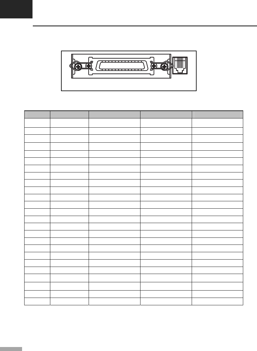
APPENDIX B
Connectors
B-2
▌B.2 IEEE1284 Parallel I/F
PARALLEL
Interface connector Drawer kick-out
Connector
▌B.2.1 IEEE 1284 Parallel I/F signal specifications
(Compatibility / Nibble / Byte mode)
Pin no. Source Compatibility mode Nibble mode Byte mode
1 Host nStrobe HostClk HostClk
2 Host / Printer Data 0 (LSB) - Data 0 (LSB)
3 Host / Printer Data 1 - Data 1
4 Host / Printer Data 2 - Data 2
5 Host / Printer Data 3 - Data 3
6 Host / Printer Data 4 - Data 4
7 Host / Printer Data 5 - Data 5
8 Host / Printer Data 6 - Data 6
9 Host / Printer Data 7 (MSB) - Data 7 (MSB)
10 Printer nAck PtrClk PtrClk
11 Printer Busy PtrBusy / Data3,7 PtrBusy
12 Printer Perror AckDataReq / Data2,6 AckDataReq
13 Printer Select Xflag / Data1,5 Xflag
14 Host nAutoFd HostBusy HostBusy
15 - NC ND ND
16 - GND GND GND
17 - GND FG FG
18 Printer Logic-H Logic-H Logic-H
19~30 - GND GND GND
31 Host nInit nInit nInit
32 Printer nFault nDataAbail / nDataAvail
33 - NC ND ND
34 Printer NC ND ND
35 Printer NC ND ND
36 Host nSelectln 1284-Active 1284-Active
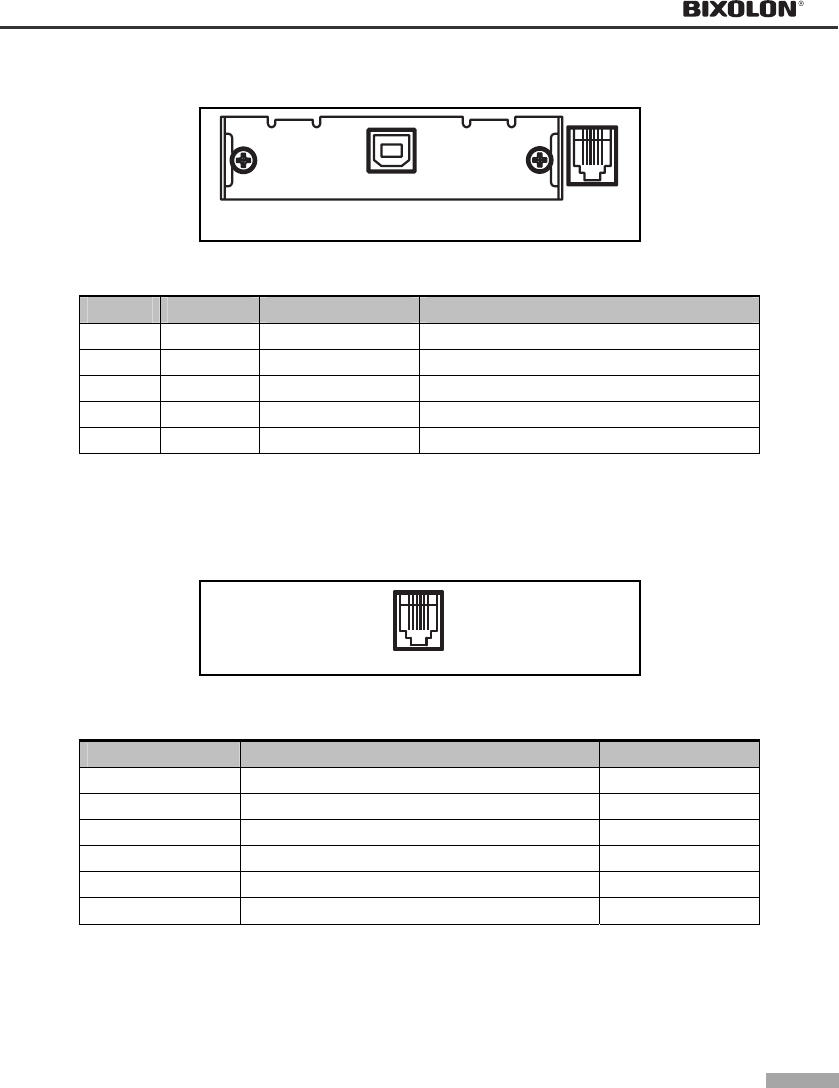
B-3
▌B.3 USB I/F
USB
Interface connector Drawer kick-out
Connector
▌B.3.1 USB I/F signal descriptions
Pin No. Signal name Assignment (Color) Function
Shell Shield Drain wire Frame ground
1 VBUS Red NC
2 D- White Differential data line
3 D+ Green Differential data line
4 GND Black Signal ground
▌B.4 Drawer kick-out
1 6
▌B.4.1 Drawer kick-out cable connection
Pin No. Description Direction
1 Signal GND -
2 Drawer kick-out driver signal #1 Output
3 Drawer Open / Close signal Input
4 +24V -
5 Drawer kick-out driver signal #2 Output
6 Signal GND -

KN02-00009E
Rev. 1.1
